EP3595818B1 - Modulare magnetanordnung - Google Patents
Modulare magnetanordnung Download PDFInfo
- Publication number
- EP3595818B1 EP3595818B1 EP18706724.4A EP18706724A EP3595818B1 EP 3595818 B1 EP3595818 B1 EP 3595818B1 EP 18706724 A EP18706724 A EP 18706724A EP 3595818 B1 EP3595818 B1 EP 3595818B1
- Authority
- EP
- European Patent Office
- Prior art keywords
- modules
- belt assembly
- magnetic belt
- module
- magnetic
- Prior art date
- Legal status (The legal status is an assumption and is not a legal conclusion. Google has not performed a legal analysis and makes no representation as to the accuracy of the status listed.)
- Active
Links
Images
Classifications
-
- B—PERFORMING OPERATIONS; TRANSPORTING
- B03—SEPARATION OF SOLID MATERIALS USING LIQUIDS OR USING PNEUMATIC TABLES OR JIGS; MAGNETIC OR ELECTROSTATIC SEPARATION OF SOLID MATERIALS FROM SOLID MATERIALS OR FLUIDS; SEPARATION BY HIGH-VOLTAGE ELECTRIC FIELDS
- B03C—MAGNETIC OR ELECTROSTATIC SEPARATION OF SOLID MATERIALS FROM SOLID MATERIALS OR FLUIDS; SEPARATION BY HIGH-VOLTAGE ELECTRIC FIELDS
- B03C1/00—Magnetic separation
- B03C1/02—Magnetic separation acting directly on the substance being separated
- B03C1/28—Magnetic plugs and dipsticks
- B03C1/288—Magnetic plugs and dipsticks disposed at the outer circumference of a recipient
-
- B—PERFORMING OPERATIONS; TRANSPORTING
- B03—SEPARATION OF SOLID MATERIALS USING LIQUIDS OR USING PNEUMATIC TABLES OR JIGS; MAGNETIC OR ELECTROSTATIC SEPARATION OF SOLID MATERIALS FROM SOLID MATERIALS OR FLUIDS; SEPARATION BY HIGH-VOLTAGE ELECTRIC FIELDS
- B03C—MAGNETIC OR ELECTROSTATIC SEPARATION OF SOLID MATERIALS FROM SOLID MATERIALS OR FLUIDS; SEPARATION BY HIGH-VOLTAGE ELECTRIC FIELDS
- B03C1/00—Magnetic separation
- B03C1/02—Magnetic separation acting directly on the substance being separated
- B03C1/025—High gradient magnetic separators
- B03C1/031—Component parts; Auxiliary operations
- B03C1/033—Component parts; Auxiliary operations characterised by the magnetic circuit
- B03C1/0332—Component parts; Auxiliary operations characterised by the magnetic circuit using permanent magnets
-
- C—CHEMISTRY; METALLURGY
- C02—TREATMENT OF WATER, WASTE WATER, SEWAGE, OR SLUDGE
- C02F—TREATMENT OF WATER, WASTE WATER, SEWAGE, OR SLUDGE
- C02F1/00—Treatment of water, waste water, or sewage
- C02F1/48—Treatment of water, waste water, or sewage with magnetic or electric fields
- C02F1/481—Treatment of water, waste water, or sewage with magnetic or electric fields using permanent magnets
- C02F1/482—Treatment of water, waste water, or sewage with magnetic or electric fields using permanent magnets located on the outer wall of the treatment device, i.e. not in contact with the liquid to be treated, e.g. detachable
-
- B—PERFORMING OPERATIONS; TRANSPORTING
- B03—SEPARATION OF SOLID MATERIALS USING LIQUIDS OR USING PNEUMATIC TABLES OR JIGS; MAGNETIC OR ELECTROSTATIC SEPARATION OF SOLID MATERIALS FROM SOLID MATERIALS OR FLUIDS; SEPARATION BY HIGH-VOLTAGE ELECTRIC FIELDS
- B03C—MAGNETIC OR ELECTROSTATIC SEPARATION OF SOLID MATERIALS FROM SOLID MATERIALS OR FLUIDS; SEPARATION BY HIGH-VOLTAGE ELECTRIC FIELDS
- B03C2201/00—Details of magnetic or electrostatic separation
- B03C2201/18—Magnetic separation whereby the particles are suspended in a liquid
-
- B—PERFORMING OPERATIONS; TRANSPORTING
- B03—SEPARATION OF SOLID MATERIALS USING LIQUIDS OR USING PNEUMATIC TABLES OR JIGS; MAGNETIC OR ELECTROSTATIC SEPARATION OF SOLID MATERIALS FROM SOLID MATERIALS OR FLUIDS; SEPARATION BY HIGH-VOLTAGE ELECTRIC FIELDS
- B03C—MAGNETIC OR ELECTROSTATIC SEPARATION OF SOLID MATERIALS FROM SOLID MATERIALS OR FLUIDS; SEPARATION BY HIGH-VOLTAGE ELECTRIC FIELDS
- B03C2201/00—Details of magnetic or electrostatic separation
- B03C2201/28—Parts being designed to be removed for cleaning purposes
Definitions
- the present invention relates to a modular magnetic assembly, in particular to a modular belt-like device which can be fitted around outer surfaces of filter housings of differing circumference.
- a magnetic filter typically comprises a housing with an inlet and an outlet, connected into a central heating system circuit so that central heating system water flows through the housing.
- a magnet is provided within the housing, to attract and retain any magnetic contamination which may be present in the water. From time to time, the magnetic filter is serviced to remove trapped magnetic contamination.
- Another type of known magnetic filter includes a housing through which central heating system water flows, and a magnet on the outside of the housing, so that magnetic contaminants are retained against an inside surface of the walls of the housing.
- This type of filter can be cleaned by isolating the filter from the central heating system circuit by closing valves, removing the externally-mounted magnet, and then opening a drain port to flush dirt out of the filter.
- one of the valves to the central heating system circuit can be opened to use the pressure of the central heating system to thoroughly flush out debris.
- One problem with this type of filter is that good performance relies on the magnets being held tightly against the outer surface of the housing. Usually, the outer surface of the housing is curved, and this presents a particular problem with accurately positioning an external magnetic element.
- US20140263077 discloses a series of modules, hinged to each other, each module carrying a magnet and the modules surrounding the outside of a pipe in use.
- DE202005015060 discloses an external magnet for an oil filter, also comprising a series of modules hinged to each other.
- US5273648 and US20060037902 each disclose a series of external magnetic elements mounted to a treatment device on a tape.
- a modular magnetic belt assembly for fitting around the external surface of a filter housing, the magnetic belt assembly comprising a plurality of modules, each module including at least one magnet, the modules being connected to each other to form the magnetic belt assembly and each module being hinged to its adjacent module(s), and a means of joining the ends of the modular magnetic belt assembly to each other to form an endless loop for fitting around the external surface of the filter housing, the magnet of each module being movable relative to the module housing and within the module housing between an in-use position for the magnet to contact the external surface of the filter housing, and an out-of-use position for holding the magnet in a position spaced from the external surface of the filter housing, when the magnetic belt assembly is fitted around the external surface of the filter housing.
- the magnetic belt assembly when placed around a filter housing, creates a magnetic filter. Because the assembly is modular, a longer or shorter belt can be produced simply by using more or fewer modules. Therefore, magnetic filters of various different sizes can be made, without the need to manufacture large numbers of custom-moulded parts. Furthermore, any suitable vessel which is already connected into a central heating system circuit, for example a water and dirt separator, can effectively be upgraded to include a magnetic capture capability, simply by installing a magnetic belt assembly around the outside surface of the existing vessel. If the vessel to be upgraded is not already fitted with suitable valves and a drain port, these can easily be fitted on the inlet and outlet, where the vessel connects into the heating circuit, to allow the filter to be cleaned.
- a water and dirt separator can effectively be upgraded to include a magnetic capture capability
- the filter body may be a purpose designed filter body.
- An example embodiment is made from stainless steel, and is substantially in the form of a cylindrical pipe.
- the diameter of the pipe, where it forms part of the filter, is ideally greater than the diameter of the central heating system circuit pipework. This allows magnetic debris to collect on the interior surface of the filter, without creating a flow restriction.
- the modules are hinged to each other, that is they are articulated to each other so that they can pivot with respect to each other. This allows the belt to fit over different curvatures for different sizes of vessel.
- the vessel will be substantially cylindrical with a curved surface, it is possible for the belt to be sufficiently flexible to pass around sharp corners, and so the filter body could be (for example) octagonal or even square in cross section.
- the hinge may be in the form of a pin and a sleeve, or may take any other form. For example, a very flexible hinge could be made by using a strip of flexible webbing between modules.
- the modules are connected to each other substantially in a row.
- the ends of the row are joined to each other.
- the joining means also include adjustable tightening means, to compensate for the discrete choice of lengths of belt which are possible due to the need to assemble a belt from an integer number of modules.
- the joining means could be, for example, a buckle similar to that used on a ski boot.
- the joining (and tightening) means will be provided by a separate component, or possibly a pair of components, which is/are attached to end(s) of the assembled belt.
- the modules in a suitable way, it may be possible to incorporate joining means into the modules, so that the belt can be assembled from multiple modules, wrapped around the filter body, and then the modules at the ends of the belt joined directly to each other.
- One way of doing this may be to provide adjustable tightening means on each module, for adjusting the spacing between adjacent modules.
- Each individual tightening means may require only a small amount of adjustability.
- the belt would be assembled with all of the tightening means on a loose setting, wrapped loosely around the outer surface of the filter body, and the modules at the ends of the belt joined directly together.
- the tightening means of each module can then be incrementally tightened, drawing the modules towards each other along the belt and around the filter body, to tighten the endless belt around the filter body and thereby retain it in place.
- each module is movable between an in-use position in contact with the filter body, and an out-of-use position spaced from the filter body. This allows the magnetic filter to be cleaned without removing the belt from the filter body.
- To clean the filter first it is isolated from the central heating system circuit, for example by closing valves. Then, each magnet is moved to the out-of-use position. This releases magnetic particles which will have been attracted out of the central heating system water and collected and retained on the inside surface of the filter body.
- a drain port can then be opened to drain the contents of the filter.
- the filter is flushed through by opening one of the valves and allowing pressurised water from the central heating system circuit to rush through the filter and out of the drain, carrying the loose magnetic particles with it.
- the drain port is closed, the filter is reconnected to the central heating system circuit, and the magnets are moved back into the in-use position.
- a mechanism is provided for moving the magnet of each module, which provides a mechanical advantage at least when moving the magnet out of the in-use position into the out-of-use position.
- the magnet may be mounted on a screw-threaded shaft.
- the magnet is mounted on a carrier having an internally screw-threaded aperture, and an externally screw-threaded shaft is connected to an operating handle, so that when the operating handle is turned to screw the externally-threaded shaft into the internally-threaded aperture, the magnet is drawn towards the handle, and away from the filter body.
- the operating handle is turned to unscrew the threaded shaft out of the threaded hole, the magnet will move away from the handle, towards the filter body.
- a spring is provided to urge the magnet towards the filter body, so that when the magnet is moved away from the body, the action of the screw thread is acting against the spring.
- At least one magnet is provided in each module.
- two magnetic billets are provided, joined by a ferromagnetic (i.e. having high susceptibility to magnetization) carrier.
- the ferromagnetic carrier may be made from mild steel. In effect this produces a 'horseshoe' magnet, with north and south poles which are directed parallel to each other, against the external surface of the filter body in the in-use position.
- Modules may be produced which have north and south poles in alternating positions, i.e. a belt could be assembled from 'A' modules and 'B' modules in the pattern ABABABA etc., so that any two adjacent magnetic poles, either between modules or within modules, are opposite poles.
- the two magnetic billets in each module may be disposed along a line which runs substantially perpendicular to a line along / around the belt, although other arrangements are possible.
- the magnet or magnetic element or each module may be mounted to the module on a pivotable bearing, preferably being pivotable substantially at the centre of the magnet or magnetic element, in all directions.
- the pivot is provided between the operating handle and the body of the module.
- a pivot may be provided on the ferromagnetic carrier which joins two magnetic billets. The pivotable bearing ensures that the magnetic poles can contact the outside surface of the filter body as closely as possible, even if the modules are slightly off-line, or if the surface of the filter body is imperfect.
- the hinge between adjacent modules is substantially in the form of a pin on one side of each module, and a barrel on the other side of each module.
- the pin of each module can be placed into the barrel of its adjacent module.
- the hinge ideally allows for enough pivoting to allow use of the same modules to form different lengths of belt for use with filter bodies of different sizes.
- the hinged joint is restricted in flexibility, for example to allow pivoting between modules of no more than 90 degrees, 60 degrees, 45 degrees or 30 degrees in different variants.
- a method of making a magnetic filter having a filter body for connection into a central heating system circuit, and an external magnetic assembly comprising the steps of:
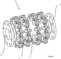
- a magnetic filter for a central heating system is indicated generally at 10.
- the magnetic filter comprises a filter body 12, which is in the form of a substantially cylindrical section of stainless steel pipe.
- Inlet and outlet ports 14, 16 are provided for connection into a central heating system circuit.
- Flanges surround the inlet and outlet ports 14, 16, for fixing the magnetic filter 10 to similar flanges on central heating system pipework.
- the magnetic filter 10 may be produced in various different sizes, for fitting to central heating system pipework having a diameter from around 2 inches (50mm) upwards.
- This particular embodiment does not include any valves or a drain port, but these can be interposed between the filter body 12 and the central heating system pipework, using off-the-shelf valve and drain components.
- This embodiment is designed for fixing to 2 inch (50mm) pipework, the bore diameter at the inlet and outlet 14, 16 is therefore nominally 2 inches / 50mm.
- a major extent of the filter body 12 has an enlarged diameter, for example of 3 inches / 75mm. This allows for magnetic debris to be attracted and retained against the internal walls of the filter body 12, without causing a restriction in the central heating system circuit.
- Modular magnetic belts 18 are wrapped around the filter body 12.
- four identical belts 18 are provided.
- Each belt is constructed of multiple modules, and each is joined together to create an endless loop around the filter body 12.
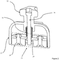
- Each module has a housing 22.
- the housing 22 is made from plastics.
- a magnetic element 24 is movable within the housing 22, from an in-use position in which the magnetic element 24 is in contact with the external surface of the filter body (12) (it is the in-use position which is shown in Figure 2 ), to an out-of-use position in which the magnetic element 24 is spaced from the external surface of the filter body (12).
- the out-of-use position is not illustrated in the drawings, but with reference to Figure 2 , the magnetic element 24 would be further towards the top of the drawing in the out-of-use position, rather than level with the bottom edge of the housing 22.
- the magnetic element is movable by means of an externally screw-threaded shaft 26 which passes through and engages an internally screw-threaded aperture 28 in the magnetic element 24.
- a spring 30 urges the magnetic element 24 towards the filter body (12) (i.e. downwards in Figure 2 ).
- the screw-threaded shaft 26 is fixed to and operated by a handle 32.
- the screw-threaded shaft 26 is a conventional right-hand screw, so when the handle 32 is turned clockwise, the magnetic element 24 is drawn away from the filter body (12), against the action of the spring 30 and also against any magnetic attraction between the magnetic element 24 and the filter body (12) or magnetic debris retained on the internal wall of the filter body (12).
- the side of the handle 32 where it meets the module body 22 i.e. the lower side of the handle 32 in Figure 2
- the side of the handle 32 where it meets the module body 22 i.e. the lower side of the handle 32 in Figure 2
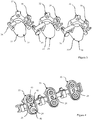
- each one includes a hinge pin 34 on one side of the module body 22, and a hinge barrel 36 on the other side.
- the module 20' on the far left of Figure 3 is slightly different, in that a slotted pin 38 is provided in place of the hinge pin.
- This module is designed to go at one end of a belt, formed with one module 20' at an end, multiple modules 20 in the middle, and then another end module (not illustrated) which has a slotted pin similar to the slotted pin 38, but in place of the hinge barrel 36.
- the hinge pins 34 slot into the hinge barrels 36 to make articulated joints between adjacent modules.
- the hinge barrel is designed to allow only around 90 degrees of rotation in the hinge, to allow enough flexibility to use assembled belts on a variety of different diameter filter bodies, but to prevent unwanted snapping of modules against each other when the belt is detached.
- the modules at either end of the belt, which have the slotted pin 38 may be joined to each other for example with a cable tie, which allows the belt to be tightened around the filter body.
- a buckle or similar may be provided for joining the ends together, or alternatively all modules could be identical, each one having a small amount of adjustability to tighten the belt of modules around the filter body.
- FIG. 4 shows the underside of the modules 20, 20', when attached and in a row to form part of a belt.
- the side of the magnetic assembly 24 which would in use be against the external surface of the filter body is visible in this figure.
- Each magnetic assembly includes two magnetic billets 40, attached to a ferromagnetic (mild steel) carrier 42.
- the topmost billet of each magnetic assembly is oriented with its north pole facing towards the filter body (i.e. out of the page in Figure 4 )
- the lower billet of each magnetic assembly 24 is oriented with its south pole facing the filter body.
- Each magnetic assembly 24 is in effect a horseshoe magnet, with the north pole towards the top of the drawing.
- the polarity of the magnetic assemblies is the same in each module 20, 20'.
- the polarity may alternate. This would mean providing an 'A' type module and a 'B' type module with the modules alternating ABABABA etc. along the belt.
- the 'A' type module could have (for example) two hinge pins 34, and the 'B' type module could have two hinge barrels 36. In this way, the modules can only be connected together in a way which alternates the polarities.
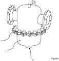
- Figure 5 shows an alternative embodiment of a magnetic filter, in that the filter body 12' is the body of an air and dirt separator of known design.
- the air and dirt separator may already be present in the system, and is likely to already be fitted with isolating valves.
- a drain port 44 is provided already as part of the air and dirt separator.
- the air and dirt separator can therefore be upgraded to add magnetic capturing capability, simply by installing a modular magnetic belt 18 according to the invention around the circumference of the air and dirt separator. Because the belt is modular, belts can be assembled to fit a wide variety of air and dirt separators, including those suited for different sized heating systems and including a wide variety of different makes and models of air and dirt separator. Preferably, several belts may be installed for enhanced magnetic capture.
- the modular magnetic belt of the invention allows for a low-cost and straightforward magnetic filter suitable for commercial sized heating systems, for example with a bore of around 2 inches (50mm) or greater. Filters can be made in many different sizes, the whole range of products only requiring a small number of different parts, since the modules in each case are identical, only the number of modules joined together in a belt will differ. Kits can be provided for upgrading air and dirt separators to include a magnetic capture capability.
Landscapes
- Life Sciences & Earth Sciences (AREA)
- Hydrology & Water Resources (AREA)
- Engineering & Computer Science (AREA)
- Environmental & Geological Engineering (AREA)
- Water Supply & Treatment (AREA)
- Chemical & Material Sciences (AREA)
- Organic Chemistry (AREA)
- Water Treatment By Electricity Or Magnetism (AREA)
- Filtering Of Dispersed Particles In Gases (AREA)
Claims (15)
- Modulare Magnetbandanordnung (18) zum Anbringen um die Außenfläche eines Filtergehäuses (12), wobei die Magnetbandanordnung (18) eine Vielzahl von Modulen (20) umfasst, wobei jedes Modul (20) ein Gehäuse (22) und mindestens einen Magneten (40) einschließt, wobei die Module (20) so aneinander angeschlossen sind, dass sie die Magnetbandanordnung (18) bilden und jedes Modul (20) an seinem/n benachbarten Modul(en) (20) angelenkt ist, und ein Mittel zum Aneinanderfügen der Enden der Magnetbandanordnung (18) so, dass eine Endlosschleife zum Anbringen um die Außenfläche des Filtergehäuses (12) gebildet wird, dadurch gekennzeichnet, dass der Magnet (40) jedes Moduls (20) in Bezug auf das Modulgehäuse (22) und innerhalb des Modulgehäuses (22) zwischen einer Gebrauchsstellung, sodass der Magnet (40) die Außenfläche des Filtergehäuses (12) berührt, und einer Nichtgebrauchsstellung bewegt werden kann, um den Magneten (40) in einer von der Außenfläche des Filtergehäuses (12) beabstandeten Stellung zu halten, wenn die Magnetbandanordnung (18) um die Außenfläche des Filtergehäuses (12) angebracht wird.
- Modulare Magnetbandanordnung (18) nach Anspruch 1, wobei das Fügemittel verstellbare Spannmittel einschließt.
- Modulare Magnetbandanordnung (18) nach einem der vorstehenden Ansprüche, wobei die Fügemittel in den Modulen (20) integriert sind, wobei die Module (20') an den Enden der Magnetbandanordnung (18) direkt aneinandergefügt werden.
- Modulare Magnetbandanordnung (18) nach einem der vorstehenden Ansprüche, wobei ein Mechanismus (26, 28), der zum Beispiel ein Schraubengewinde einschließt, bereitgestellt ist, um den Magneten (40) jedes Moduls (20) zu bewegen, wobei der Mechanismus (26, 28) einen mechanischen Vorteil bietet, der größer als zumindest einer ist,, wenn der Magnet (40) aus der Gebrauchsstellung in die Nichtgebrauchsstellung bewegt wird.
- Modulare Magnetbandanordnung (18) nach Anspruch 4, wobei der Mechanismus (26, 28) mit einem Betätigungsgriff (32) manuell betätigt werden kann.
- Modulare Magnetbandanordnung (18) nach einem der vorstehenden Ansprüche, wobei in jedem Modul (20) zwei Magneten (40) bereitgestellt sind, wobei jeder der Magneten (40) an einem ferromagnetischen Träger (42) montiert ist, und wobei der Nordpol eines Magneten (40) im Gebrauch dem Filtergehäuse (12) zugewandt ist, und der Südpol des anderen Magneten (40) im Gebrauch dem Filtergehäuse (12) zugewandt ist.
- Modulare Magnetbandanordnung (18) nach Anspruch 6, wobei Module eines ersten Typs und Module eines zweiten Typs bereitgestellt sind, wobei bei den Modulen des zweiten Typs, in Bezug auf die Module des ersten Typs, die Magnete (40) mit umgekehrter Polung positioniert sind.
- Modulare Magnetbandanordnung (18) nach Anspruch 7, wobei Module des ersten Typs und Module des zweiten Typs abwechselnd entlang der Länge der zusammengebauten Magnetbandanordnung (18) angeordnet sind.
- Modulare Magnetbandanordnung (18) nach einem der Ansprüche 6 bis 8, wobei die zwei Magnete (40) jedes Moduls (20) entlang einer Linie angeordnet sind, die im Wesentlichen senkrecht zu einer Linie entlang der Magnetbandanordnung (18) verläuft.
- Modulare Magnetbandanordnung (18) nach einem der vorstehenden Ansprüche, wobei der/die Magnet(e) (40) jedes Moduls (20) über ein Schwenklager am Modulgehäuse (22) montiert sind.
- Magnetfilter (10) für eine Zentralheizungsanlage, umfassend:eine modulare Magnetbandanordnung (18) nach einem der vorstehenden Ansprüche; undein Filtergehäuse (12), zum Beispiel den Körper eines Luft- und Schmutzabscheiders (12'),wobei die Magnetbandanordnung (18) um das Filtergehäuse (12, 12') angeordnet ist, wobei sich der/die Magnet(e) (40) jedes Moduls (20) in der Gebrauchsstellung mit einer Außenfläche des Filtergehäuses (12, 12') in Berührung befinden, und in der Nichtgebrauchsstellung von der Außenfläche des Filtergehäuses (12, 12') beabstandet sind.
- Verfahren zur Herstellung eines Magnetfilters (10), der ein Filtergehäuse (12, 12') zum Anschließen an einen Kreislauf einer Zentralheizungsanlage, und eine externe Magnetanordnung (18) aufweist, wobei das Verfahren die Schritte umfasst des:Zusammenbauens eines modularen Magnetbands (18) aus einer Vielzahl von Modulen (20), wobei jedes Modul (20) ein Modulgehäuse (22) und einen Magneten (40) aufweist, wobei der Magnet (40) jedes Moduls (20) in Bezug auf das Modulgehäuse (22) und innerhalb des Modulgehäuses (22) zwischen einer Gebrauchsstellung, sodass der Magnet (40) die Außenfläche des Filtergehäuses (12, 12') berührt, und einer Nichtgebrauchsstellung bewegt werden kann, um den Magneten (40) in einer von der Außenfläche des Filtergehäuses (12, 12') beabstandeten Stellung zu halten, wobei die Module (20) der Magnetbandanordnung (18) aneinander angeschlossen werden und jedes Modul (20) an sein(e) benachbartes/n Modul(e) (20) angelenkt wird, wobei die Anzahl von Modulen (20) in der Magnetbandanordnung (18) je nach einer Länge einer Strecke um eine Außenfläche des Filtergehäuses (12, 12') ausgewählt wird;Wickelns der Magnetbandanordnung (18) um eine Außenfläche des Filtergehäuses (12, 12'); undAneinanderfügens der Enden der Magnetbandanordnung (18), sodass eine Endlosschleife gebildet wird, die um die Außenfläche des Filtergehäuses (12, 12') ortsfest fixiert ist.
- Verfahren zur Herstellung eines Magnetfilters (10) nach Anspruch 12, wobei das Fügemittel verstellbare Spannmittel einschließt, und der Schritt des Zusammenfügens der Enden der Magnetbandanordnung (18) das Spannen der Magnetbandanordnung (18) um das Filtergehäuse (12, 12') einschließt, um die Magnetbandanordnung (18) ortsfest um das Filtergehäuse (12, 12') zu halten.
- Verfahren zur Herstellung eines Magnetfilters (10) nach Anspruch 12 oder 13, wobei das Magnetband (18) aus Modulen eines ersten Typs und Modulen eines zweiten Typs zusammengebaut wird, wobei bei den Modulen des zweiten Typs, in Bezug auf die Module des ersten Typs, Magnet(e) (40) mit umgekehrter Polung positioniert sind, und wobei das Magnetband (18) so zusammengebaut wird, dass sich Module des ersten Typs entlang der Länge der Magnetbandanordnung (18) mit Modulen des zweiten Typs abwechseln.
- Verfahren zur Herstellung eines Magnetfilters (10) nach einem der Ansprüche 12 bis 14, wobei es sich beim Filtergehäuse um den Körper eines Luft- und Schmutzabscheiders (12') handelt.
Priority Applications (2)
| Application Number | Priority Date | Filing Date | Title |
|---|---|---|---|
| EP21151285.0A EP3842151A1 (de) | 2017-03-14 | 2018-02-21 | Luft-schmutz-abscheider mit modularer magnetischer anordnung |
| PL18706724T PL3595818T3 (pl) | 2017-03-14 | 2018-02-21 | Modułowy zespół magnetyczny |
Applications Claiming Priority (2)
| Application Number | Priority Date | Filing Date | Title |
|---|---|---|---|
| GB1704015.5A GB2560532B (en) | 2017-03-14 | 2017-03-14 | Modular magnetic assembly |
| PCT/EP2018/054230 WO2018166769A1 (en) | 2017-03-14 | 2018-02-21 | Modular magnetic assembly |
Related Child Applications (2)
| Application Number | Title | Priority Date | Filing Date |
|---|---|---|---|
| EP21151285.0A Division EP3842151A1 (de) | 2017-03-14 | 2018-02-21 | Luft-schmutz-abscheider mit modularer magnetischer anordnung |
| EP21151285.0A Division-Into EP3842151A1 (de) | 2017-03-14 | 2018-02-21 | Luft-schmutz-abscheider mit modularer magnetischer anordnung |
Publications (2)
| Publication Number | Publication Date |
|---|---|
| EP3595818A1 EP3595818A1 (de) | 2020-01-22 |
| EP3595818B1 true EP3595818B1 (de) | 2021-03-17 |
Family
ID=58605322
Family Applications (2)
| Application Number | Title | Priority Date | Filing Date |
|---|---|---|---|
| EP18706724.4A Active EP3595818B1 (de) | 2017-03-14 | 2018-02-21 | Modulare magnetanordnung |
| EP21151285.0A Withdrawn EP3842151A1 (de) | 2017-03-14 | 2018-02-21 | Luft-schmutz-abscheider mit modularer magnetischer anordnung |
Family Applications After (1)
| Application Number | Title | Priority Date | Filing Date |
|---|---|---|---|
| EP21151285.0A Withdrawn EP3842151A1 (de) | 2017-03-14 | 2018-02-21 | Luft-schmutz-abscheider mit modularer magnetischer anordnung |
Country Status (8)
| Country | Link |
|---|---|
| US (1) | US11440023B2 (de) |
| EP (2) | EP3595818B1 (de) |
| CN (2) | CN113117888B (de) |
| DK (1) | DK3595818T3 (de) |
| GB (1) | GB2560532B (de) |
| HU (1) | HUE054927T2 (de) |
| PL (1) | PL3595818T3 (de) |
| WO (1) | WO2018166769A1 (de) |
Families Citing this family (5)
| Publication number | Priority date | Publication date | Assignee | Title |
|---|---|---|---|---|
| GB201719427D0 (en) * | 2017-11-23 | 2018-01-10 | Vexo International (Uk) Ltd | Apparatus for and method of fluid treatment |
| CN111495584A (zh) * | 2020-04-26 | 2020-08-07 | 潘学勇 | 一种电力绝缘子制作泥料过筛除铁设备及方法 |
| CN112403677B (zh) * | 2020-11-11 | 2022-09-30 | 宁波宁兴涌优饲料有限公司 | 一种用于畜牧饲料加工机械的除铁渣装置 |
| GB2600797B (en) | 2021-06-10 | 2023-05-31 | Adey Holdings 2008 Ltd | Insulating jacket for a filter |
| CN119683746A (zh) * | 2025-02-24 | 2025-03-25 | 洛阳思谋思能源科技有限公司 | 一种电磁水处理循环利用装置及其使用方法 |
Family Cites Families (20)
| Publication number | Priority date | Publication date | Assignee | Title |
|---|---|---|---|---|
| US2800230A (en) * | 1953-07-15 | 1957-07-23 | Jean Thoma | Magnetic separators |
| US5273648A (en) * | 1992-07-15 | 1993-12-28 | Caiozza Joseph C | Filter cartridge magnetic belt |
| US5269916A (en) * | 1992-09-11 | 1993-12-14 | Colonel Clair | Pipe protector/fluid ionizer employing magnetic condenser for producing concentrated force lines perpendicular to fluid flow |
| HUT76505A (en) | 1993-09-07 | 1997-09-29 | Brunsting | Magnetic filter assembly |
| NL1001427C2 (nl) * | 1995-10-16 | 1997-04-17 | Paulus Wolfs | Inrichting voor het verwijderen van magnetiseerbare delen. |
| US5714063A (en) * | 1996-05-28 | 1998-02-03 | Brunsting; William J. | Apparatus for the removal of ferrous particles from liquids |
| WO2003019583A1 (en) * | 2001-08-24 | 2003-03-06 | The Aussie Kids Toy Company Pty Limited | Switchable magnetic device |
| JP4085181B2 (ja) * | 1999-12-24 | 2008-05-14 | 富田 実 | 水処理具 |
| DE20010223U1 (de) * | 2000-06-07 | 2000-08-17 | Comfort-Sinusverteiler GmbH & Co. KG, 48493 Wettringen | Hydraulische Weiche für eine Heizungsanlage |
| US6638425B2 (en) * | 2001-03-28 | 2003-10-28 | Filter Specialists, Inc. | Magnetic filter |
| JP2004017022A (ja) * | 2002-06-20 | 2004-01-22 | Iihatova Amenity Service:Kk | 磁気処理装置 |
| US7641793B2 (en) * | 2004-08-17 | 2010-01-05 | Paul Michael Pedersen | Aqueous liquid treatment |
| DE202005015060U1 (de) * | 2005-04-25 | 2005-12-15 | Liu, Chun-Hui, Hsinchuang | Magnetisiergerät für Ölfilter |
| GB2476825B (en) * | 2010-01-12 | 2011-12-07 | Eclipse Magnetics Ltd | Magnetic filtration apparatus |
| DE102010041621B4 (de) * | 2010-09-29 | 2016-11-03 | Hahn-Schickard-Gesellschaft für angewandte Forschung e.V. | Verfahren zum Transport magnetischer Partikel |
| ITMI20111687A1 (it) * | 2011-09-19 | 2013-03-20 | Caleffi Spa | Separatore magnetico di particelle per impianti termici |
| US8900449B2 (en) * | 2012-03-13 | 2014-12-02 | Cpc Corporation, Taiwan | Magnetic filter for refining and chemical industries |
| GB2500908B (en) * | 2012-04-04 | 2015-02-25 | Eclipse Magnetics Ltd | Magnetic filtration device |
| US9719738B2 (en) * | 2013-03-14 | 2017-08-01 | Hydroflux Technology, Llc | Apparatus and method for applying magnetic fields to fluid flows |
| CN103920583B (zh) * | 2014-03-27 | 2016-08-24 | 安徽蒂王集团食品有限公司 | 一种新型的除杂装置 |
-
2017
- 2017-03-14 GB GB1704015.5A patent/GB2560532B/en not_active Expired - Fee Related
-
2018
- 2018-02-21 PL PL18706724T patent/PL3595818T3/pl unknown
- 2018-02-21 CN CN202110302738.3A patent/CN113117888B/zh not_active Expired - Fee Related
- 2018-02-21 WO PCT/EP2018/054230 patent/WO2018166769A1/en not_active Ceased
- 2018-02-21 HU HUE18706724A patent/HUE054927T2/hu unknown
- 2018-02-21 US US16/493,852 patent/US11440023B2/en active Active
- 2018-02-21 DK DK18706724.4T patent/DK3595818T3/da active
- 2018-02-21 EP EP18706724.4A patent/EP3595818B1/de active Active
- 2018-02-21 EP EP21151285.0A patent/EP3842151A1/de not_active Withdrawn
- 2018-02-21 CN CN201880026536.7A patent/CN110582355B/zh not_active Expired - Fee Related
Non-Patent Citations (1)
| Title |
|---|
| None * |
Also Published As
| Publication number | Publication date |
|---|---|
| US20200078797A1 (en) | 2020-03-12 |
| US11440023B2 (en) | 2022-09-13 |
| HUE054927T2 (hu) | 2021-10-28 |
| GB201704015D0 (en) | 2017-04-26 |
| EP3842151A1 (de) | 2021-06-30 |
| CN110582355B (zh) | 2021-02-26 |
| WO2018166769A1 (en) | 2018-09-20 |
| CN113117888B (zh) | 2023-07-25 |
| CN110582355A (zh) | 2019-12-17 |
| GB2560532B (en) | 2019-10-30 |
| DK3595818T3 (da) | 2021-06-21 |
| PL3595818T3 (pl) | 2021-12-20 |
| EP3595818A1 (de) | 2020-01-22 |
| GB2560532A (en) | 2018-09-19 |
| CN113117888A (zh) | 2021-07-16 |
Similar Documents
| Publication | Publication Date | Title |
|---|---|---|
| EP3595818B1 (de) | Modulare magnetanordnung | |
| EP3478421B1 (de) | Magnetischer filter für ein zentralheizungssystem | |
| EP3280536B1 (de) | Magnetischer filter mit ablauf und abnehmbarem externem magnetischen element | |
| DE19519438A1 (de) | Luftfilter, insbesondere für die Reinigung von Verbrennungsluft für Brennkraftmaschinen | |
| US6962655B1 (en) | Filter accessory for use in swimming pool water flow system | |
| GB2561760A (en) | Air-and-dirt separator with modular magnetic assembly | |
| KR102192343B1 (ko) | 스트레이너장치 | |
| US10458137B1 (en) | Pool skimmer opening closure device and method | |
| WO2019206763A1 (en) | Magnetic filter | |
| US20210062527A1 (en) | Pool skimmer devices, systems, and methods | |
| KR20190109149A (ko) | 유체 여과장치 | |
| DE202013003117U1 (de) | Trommelfilter mit Bandvorabscheider | |
| US20130193043A1 (en) | Cleaning of swimming pools | |
| DE202013100421U1 (de) | Ölnebelabscheider | |
| KR20190102474A (ko) | 고형물 탈수장치 | |
| US20040060853A1 (en) | Pond fountain cartridge filter | |
| US11001415B1 (en) | Temporary plug apparatus for a port of a manifold of a pool filter system | |
| KR102951755B1 (ko) | 스트레이너 | |
| KR101367147B1 (ko) | 스트레이너 조립체 및 그 청소방법 | |
| CN206017779U (zh) | 一种y型过滤器用截流挡板 | |
| US20240157278A1 (en) | FilterCover by CleanMyPool | |
| TW202325948A (zh) | 縱型排水疏水閥 | |
| RU2244201C1 (ru) | Фильтр | |
| DE1447382U (de) | ||
| KR20170054777A (ko) | 스트레이너 |
Legal Events
| Date | Code | Title | Description |
|---|---|---|---|
| STAA | Information on the status of an ep patent application or granted ep patent |
Free format text: STATUS: UNKNOWN |
|
| STAA | Information on the status of an ep patent application or granted ep patent |
Free format text: STATUS: THE INTERNATIONAL PUBLICATION HAS BEEN MADE |
|
| PUAI | Public reference made under article 153(3) epc to a published international application that has entered the european phase |
Free format text: ORIGINAL CODE: 0009012 |
|
| STAA | Information on the status of an ep patent application or granted ep patent |
Free format text: STATUS: REQUEST FOR EXAMINATION WAS MADE |
|
| 17P | Request for examination filed |
Effective date: 20190906 |
|
| AK | Designated contracting states |
Kind code of ref document: A1 Designated state(s): AL AT BE BG CH CY CZ DE DK EE ES FI FR GB GR HR HU IE IS IT LI LT LU LV MC MK MT NL NO PL PT RO RS SE SI SK SM TR |
|
| AX | Request for extension of the european patent |
Extension state: BA ME |
|
| DAV | Request for validation of the european patent (deleted) | ||
| DAX | Request for extension of the european patent (deleted) | ||
| GRAP | Despatch of communication of intention to grant a patent |
Free format text: ORIGINAL CODE: EPIDOSNIGR1 |
|
| STAA | Information on the status of an ep patent application or granted ep patent |
Free format text: STATUS: GRANT OF PATENT IS INTENDED |
|
| INTG | Intention to grant announced |
Effective date: 20200916 |
|
| GRAS | Grant fee paid |
Free format text: ORIGINAL CODE: EPIDOSNIGR3 |
|
| GRAA | (expected) grant |
Free format text: ORIGINAL CODE: 0009210 |
|
| STAA | Information on the status of an ep patent application or granted ep patent |
Free format text: STATUS: THE PATENT HAS BEEN GRANTED |
|
| AK | Designated contracting states |
Kind code of ref document: B1 Designated state(s): AL AT BE BG CH CY CZ DE DK EE ES FI FR GB GR HR HU IE IS IT LI LT LU LV MC MK MT NL NO PL PT RO RS SE SI SK SM TR |
|
| REG | Reference to a national code |
Ref country code: GB Ref legal event code: FG4D |
|
| REG | Reference to a national code |
Ref country code: CH Ref legal event code: EP |
|
| REG | Reference to a national code |
Ref country code: DE Ref legal event code: R096 Ref document number: 602018014051 Country of ref document: DE |
|
| REG | Reference to a national code |
Ref country code: IE Ref legal event code: FG4D |
|
| REG | Reference to a national code |
Ref country code: AT Ref legal event code: REF Ref document number: 1371747 Country of ref document: AT Kind code of ref document: T Effective date: 20210415 |
|
| REG | Reference to a national code |
Ref country code: NL Ref legal event code: FP |
|
| REG | Reference to a national code |
Ref country code: DK Ref legal event code: T3 Effective date: 20210615 |
|
| REG | Reference to a national code |
Ref country code: SE Ref legal event code: TRGR |
|
| REG | Reference to a national code |
Ref country code: NO Ref legal event code: T2 Effective date: 20210317 |
|
| RAP4 | Party data changed (patent owner data changed or rights of a patent transferred) |
Owner name: ADEY HOLDINGS (2008) LIMITED |
|
| REG | Reference to a national code |
Ref country code: LT Ref legal event code: MG9D |
|
| PG25 | Lapsed in a contracting state [announced via postgrant information from national office to epo] |
Ref country code: HR Free format text: LAPSE BECAUSE OF FAILURE TO SUBMIT A TRANSLATION OF THE DESCRIPTION OR TO PAY THE FEE WITHIN THE PRESCRIBED TIME-LIMIT Effective date: 20210317 Ref country code: FI Free format text: LAPSE BECAUSE OF FAILURE TO SUBMIT A TRANSLATION OF THE DESCRIPTION OR TO PAY THE FEE WITHIN THE PRESCRIBED TIME-LIMIT Effective date: 20210317 Ref country code: GR Free format text: LAPSE BECAUSE OF FAILURE TO SUBMIT A TRANSLATION OF THE DESCRIPTION OR TO PAY THE FEE WITHIN THE PRESCRIBED TIME-LIMIT Effective date: 20210618 Ref country code: BG Free format text: LAPSE BECAUSE OF FAILURE TO SUBMIT A TRANSLATION OF THE DESCRIPTION OR TO PAY THE FEE WITHIN THE PRESCRIBED TIME-LIMIT Effective date: 20210617 |
|
| PG25 | Lapsed in a contracting state [announced via postgrant information from national office to epo] |
Ref country code: LV Free format text: LAPSE BECAUSE OF FAILURE TO SUBMIT A TRANSLATION OF THE DESCRIPTION OR TO PAY THE FEE WITHIN THE PRESCRIBED TIME-LIMIT Effective date: 20210317 Ref country code: RS Free format text: LAPSE BECAUSE OF FAILURE TO SUBMIT A TRANSLATION OF THE DESCRIPTION OR TO PAY THE FEE WITHIN THE PRESCRIBED TIME-LIMIT Effective date: 20210317 |
|
| REG | Reference to a national code |
Ref country code: HU Ref legal event code: AG4A Ref document number: E054927 Country of ref document: HU |
|
| PG25 | Lapsed in a contracting state [announced via postgrant information from national office to epo] |
Ref country code: EE Free format text: LAPSE BECAUSE OF FAILURE TO SUBMIT A TRANSLATION OF THE DESCRIPTION OR TO PAY THE FEE WITHIN THE PRESCRIBED TIME-LIMIT Effective date: 20210317 Ref country code: LT Free format text: LAPSE BECAUSE OF FAILURE TO SUBMIT A TRANSLATION OF THE DESCRIPTION OR TO PAY THE FEE WITHIN THE PRESCRIBED TIME-LIMIT Effective date: 20210317 Ref country code: SM Free format text: LAPSE BECAUSE OF FAILURE TO SUBMIT A TRANSLATION OF THE DESCRIPTION OR TO PAY THE FEE WITHIN THE PRESCRIBED TIME-LIMIT Effective date: 20210317 |
|
| PG25 | Lapsed in a contracting state [announced via postgrant information from national office to epo] |
Ref country code: IS Free format text: LAPSE BECAUSE OF FAILURE TO SUBMIT A TRANSLATION OF THE DESCRIPTION OR TO PAY THE FEE WITHIN THE PRESCRIBED TIME-LIMIT Effective date: 20210717 Ref country code: SK Free format text: LAPSE BECAUSE OF FAILURE TO SUBMIT A TRANSLATION OF THE DESCRIPTION OR TO PAY THE FEE WITHIN THE PRESCRIBED TIME-LIMIT Effective date: 20210317 Ref country code: RO Free format text: LAPSE BECAUSE OF FAILURE TO SUBMIT A TRANSLATION OF THE DESCRIPTION OR TO PAY THE FEE WITHIN THE PRESCRIBED TIME-LIMIT Effective date: 20210317 Ref country code: PT Free format text: LAPSE BECAUSE OF FAILURE TO SUBMIT A TRANSLATION OF THE DESCRIPTION OR TO PAY THE FEE WITHIN THE PRESCRIBED TIME-LIMIT Effective date: 20210719 |
|
| REG | Reference to a national code |
Ref country code: DE Ref legal event code: R097 Ref document number: 602018014051 Country of ref document: DE |
|
| PLBE | No opposition filed within time limit |
Free format text: ORIGINAL CODE: 0009261 |
|
| STAA | Information on the status of an ep patent application or granted ep patent |
Free format text: STATUS: NO OPPOSITION FILED WITHIN TIME LIMIT |
|
| PG25 | Lapsed in a contracting state [announced via postgrant information from national office to epo] |
Ref country code: ES Free format text: LAPSE BECAUSE OF FAILURE TO SUBMIT A TRANSLATION OF THE DESCRIPTION OR TO PAY THE FEE WITHIN THE PRESCRIBED TIME-LIMIT Effective date: 20210317 Ref country code: AL Free format text: LAPSE BECAUSE OF FAILURE TO SUBMIT A TRANSLATION OF THE DESCRIPTION OR TO PAY THE FEE WITHIN THE PRESCRIBED TIME-LIMIT Effective date: 20210317 |
|
| 26N | No opposition filed |
Effective date: 20211220 |
|
| PG25 | Lapsed in a contracting state [announced via postgrant information from national office to epo] |
Ref country code: SI Free format text: LAPSE BECAUSE OF FAILURE TO SUBMIT A TRANSLATION OF THE DESCRIPTION OR TO PAY THE FEE WITHIN THE PRESCRIBED TIME-LIMIT Effective date: 20210317 |
|
| PG25 | Lapsed in a contracting state [announced via postgrant information from national office to epo] |
Ref country code: IT Free format text: LAPSE BECAUSE OF FAILURE TO SUBMIT A TRANSLATION OF THE DESCRIPTION OR TO PAY THE FEE WITHIN THE PRESCRIBED TIME-LIMIT Effective date: 20210317 |
|
| PG25 | Lapsed in a contracting state [announced via postgrant information from national office to epo] |
Ref country code: IS Free format text: LAPSE BECAUSE OF FAILURE TO SUBMIT A TRANSLATION OF THE DESCRIPTION OR TO PAY THE FEE WITHIN THE PRESCRIBED TIME-LIMIT Effective date: 20210717 |
|
| PG25 | Lapsed in a contracting state [announced via postgrant information from national office to epo] |
Ref country code: MC Free format text: LAPSE BECAUSE OF FAILURE TO SUBMIT A TRANSLATION OF THE DESCRIPTION OR TO PAY THE FEE WITHIN THE PRESCRIBED TIME-LIMIT Effective date: 20210317 |
|
| PG25 | Lapsed in a contracting state [announced via postgrant information from national office to epo] |
Ref country code: LU Free format text: LAPSE BECAUSE OF NON-PAYMENT OF DUE FEES Effective date: 20220221 |
|
| PGFP | Annual fee paid to national office [announced via postgrant information from national office to epo] |
Ref country code: SE Payment date: 20221221 Year of fee payment: 6 Ref country code: NO Payment date: 20221222 Year of fee payment: 6 Ref country code: IE Payment date: 20221205 Year of fee payment: 6 Ref country code: GB Payment date: 20221208 Year of fee payment: 6 Ref country code: DK Payment date: 20221221 Year of fee payment: 6 |
|
| PGFP | Annual fee paid to national office [announced via postgrant information from national office to epo] |
Ref country code: NL Payment date: 20230216 Year of fee payment: 6 |
|
| PGFP | Annual fee paid to national office [announced via postgrant information from national office to epo] |
Ref country code: FR Payment date: 20230221 Year of fee payment: 6 Ref country code: CZ Payment date: 20230213 Year of fee payment: 6 Ref country code: CH Payment date: 20230307 Year of fee payment: 6 Ref country code: AT Payment date: 20230109 Year of fee payment: 6 |
|
| PGFP | Annual fee paid to national office [announced via postgrant information from national office to epo] |
Ref country code: TR Payment date: 20230220 Year of fee payment: 6 Ref country code: PL Payment date: 20230210 Year of fee payment: 6 Ref country code: HU Payment date: 20230220 Year of fee payment: 6 Ref country code: DE Payment date: 20230109 Year of fee payment: 6 Ref country code: BE Payment date: 20230216 Year of fee payment: 6 |
|
| P01 | Opt-out of the competence of the unified patent court (upc) registered |
Effective date: 20230527 |
|
| PG25 | Lapsed in a contracting state [announced via postgrant information from national office to epo] |
Ref country code: MK Free format text: LAPSE BECAUSE OF FAILURE TO SUBMIT A TRANSLATION OF THE DESCRIPTION OR TO PAY THE FEE WITHIN THE PRESCRIBED TIME-LIMIT Effective date: 20210317 Ref country code: CY Free format text: LAPSE BECAUSE OF FAILURE TO SUBMIT A TRANSLATION OF THE DESCRIPTION OR TO PAY THE FEE WITHIN THE PRESCRIBED TIME-LIMIT Effective date: 20210317 |
|
| REG | Reference to a national code |
Ref country code: DE Ref legal event code: R119 Ref document number: 602018014051 Country of ref document: DE |
|
| REG | Reference to a national code |
Ref country code: DK Ref legal event code: EBP Effective date: 20240229 |
|
| PG25 | Lapsed in a contracting state [announced via postgrant information from national office to epo] |
Ref country code: MT Free format text: LAPSE BECAUSE OF FAILURE TO SUBMIT A TRANSLATION OF THE DESCRIPTION OR TO PAY THE FEE WITHIN THE PRESCRIBED TIME-LIMIT Effective date: 20210317 |
|
| REG | Reference to a national code |
Ref country code: CH Ref legal event code: PL |
|
| REG | Reference to a national code |
Ref country code: SE Ref legal event code: EUG |
|
| REG | Reference to a national code |
Ref country code: NL Ref legal event code: MM Effective date: 20240301 |
|
| REG | Reference to a national code |
Ref country code: AT Ref legal event code: MM01 Ref document number: 1371747 Country of ref document: AT Kind code of ref document: T Effective date: 20240221 |
|
| PG25 | Lapsed in a contracting state [announced via postgrant information from national office to epo] |
Ref country code: CH Free format text: LAPSE BECAUSE OF NON-PAYMENT OF DUE FEES Effective date: 20240229 |
|
| GBPC | Gb: european patent ceased through non-payment of renewal fee |
Effective date: 20240221 |
|
| PG25 | Lapsed in a contracting state [announced via postgrant information from national office to epo] |
Ref country code: CZ Free format text: LAPSE BECAUSE OF NON-PAYMENT OF DUE FEES Effective date: 20240221 |
|
| PG25 | Lapsed in a contracting state [announced via postgrant information from national office to epo] |
Ref country code: AT Free format text: LAPSE BECAUSE OF NON-PAYMENT OF DUE FEES Effective date: 20240221 |
|
| PG25 | Lapsed in a contracting state [announced via postgrant information from national office to epo] |
Ref country code: HU Free format text: LAPSE BECAUSE OF NON-PAYMENT OF DUE FEES Effective date: 20240222 |
|
| PG25 | Lapsed in a contracting state [announced via postgrant information from national office to epo] |
Ref country code: NO Free format text: LAPSE BECAUSE OF NON-PAYMENT OF DUE FEES Effective date: 20240229 Ref country code: HU Free format text: LAPSE BECAUSE OF NON-PAYMENT OF DUE FEES Effective date: 20240222 Ref country code: CZ Free format text: LAPSE BECAUSE OF NON-PAYMENT OF DUE FEES Effective date: 20240221 Ref country code: CH Free format text: LAPSE BECAUSE OF NON-PAYMENT OF DUE FEES Effective date: 20240229 Ref country code: AT Free format text: LAPSE BECAUSE OF NON-PAYMENT OF DUE FEES Effective date: 20240221 |
|
| PG25 | Lapsed in a contracting state [announced via postgrant information from national office to epo] |
Ref country code: NL Free format text: LAPSE BECAUSE OF NON-PAYMENT OF DUE FEES Effective date: 20240301 |
|
| PG25 | Lapsed in a contracting state [announced via postgrant information from national office to epo] |
Ref country code: NL Free format text: LAPSE BECAUSE OF NON-PAYMENT OF DUE FEES Effective date: 20240301 |
|
| REG | Reference to a national code |
Ref country code: BE Ref legal event code: MM Effective date: 20240229 |
|
| PG25 | Lapsed in a contracting state [announced via postgrant information from national office to epo] |
Ref country code: DE Free format text: LAPSE BECAUSE OF NON-PAYMENT OF DUE FEES Effective date: 20240903 |
|
| PG25 | Lapsed in a contracting state [announced via postgrant information from national office to epo] |
Ref country code: DK Free format text: LAPSE BECAUSE OF NON-PAYMENT OF DUE FEES Effective date: 20240229 |
|
| PG25 | Lapsed in a contracting state [announced via postgrant information from national office to epo] |
Ref country code: BE Free format text: LAPSE BECAUSE OF NON-PAYMENT OF DUE FEES Effective date: 20240229 |
|
| PG25 | Lapsed in a contracting state [announced via postgrant information from national office to epo] |
Ref country code: GB Free format text: LAPSE BECAUSE OF NON-PAYMENT OF DUE FEES Effective date: 20240221 |
|
| PG25 | Lapsed in a contracting state [announced via postgrant information from national office to epo] |
Ref country code: FR Free format text: LAPSE BECAUSE OF NON-PAYMENT OF DUE FEES Effective date: 20240229 |
|
| PG25 | Lapsed in a contracting state [announced via postgrant information from national office to epo] |
Ref country code: IE Free format text: LAPSE BECAUSE OF NON-PAYMENT OF DUE FEES Effective date: 20240221 |
|
| PG25 | Lapsed in a contracting state [announced via postgrant information from national office to epo] |
Ref country code: IE Free format text: LAPSE BECAUSE OF NON-PAYMENT OF DUE FEES Effective date: 20240221 Ref country code: GB Free format text: LAPSE BECAUSE OF NON-PAYMENT OF DUE FEES Effective date: 20240221 Ref country code: FR Free format text: LAPSE BECAUSE OF NON-PAYMENT OF DUE FEES Effective date: 20240229 Ref country code: DK Free format text: LAPSE BECAUSE OF NON-PAYMENT OF DUE FEES Effective date: 20240229 Ref country code: DE Free format text: LAPSE BECAUSE OF NON-PAYMENT OF DUE FEES Effective date: 20240903 Ref country code: BE Free format text: LAPSE BECAUSE OF NON-PAYMENT OF DUE FEES Effective date: 20240229 |
|
| PG25 | Lapsed in a contracting state [announced via postgrant information from national office to epo] |
Ref country code: SE Free format text: LAPSE BECAUSE OF NON-PAYMENT OF DUE FEES Effective date: 20240222 |
|
| PG25 | Lapsed in a contracting state [announced via postgrant information from national office to epo] |
Ref country code: PL Free format text: LAPSE BECAUSE OF NON-PAYMENT OF DUE FEES Effective date: 20240221 |