EP3595504B1 - Geschirrspülmaschine und verfahren zur steuerung davon - Google Patents
Geschirrspülmaschine und verfahren zur steuerung davon Download PDFInfo
- Publication number
- EP3595504B1 EP3595504B1 EP18767984.0A EP18767984A EP3595504B1 EP 3595504 B1 EP3595504 B1 EP 3595504B1 EP 18767984 A EP18767984 A EP 18767984A EP 3595504 B1 EP3595504 B1 EP 3595504B1
- Authority
- EP
- European Patent Office
- Prior art keywords
- wash water
- filter
- sump
- wash
- foreign substances
- Prior art date
- Legal status (The legal status is an assumption and is not a legal conclusion. Google has not performed a legal analysis and makes no representation as to the accuracy of the status listed.)
- Active
Links
Images


Classifications
-
- A—HUMAN NECESSITIES
- A47—FURNITURE; DOMESTIC ARTICLES OR APPLIANCES; COFFEE MILLS; SPICE MILLS; SUCTION CLEANERS IN GENERAL
- A47L—DOMESTIC WASHING OR CLEANING; SUCTION CLEANERS IN GENERAL
- A47L15/00—Washing or rinsing machines for crockery or tableware
- A47L15/0018—Controlling processes, i.e. processes to control the operation of the machine characterised by the purpose or target of the control
- A47L15/0021—Regulation of operational steps within the washing processes, e.g. optimisation or improvement of operational steps depending from the detergent nature or from the condition of the crockery
- A47L15/0031—Water discharge phases
-
- A—HUMAN NECESSITIES
- A47—FURNITURE; DOMESTIC ARTICLES OR APPLIANCES; COFFEE MILLS; SPICE MILLS; SUCTION CLEANERS IN GENERAL
- A47L—DOMESTIC WASHING OR CLEANING; SUCTION CLEANERS IN GENERAL
- A47L15/00—Washing or rinsing machines for crockery or tableware
- A47L15/0002—Washing processes, i.e. machine working principles characterised by phases or operational steps
- A47L15/0005—Rinsing phases, e.g. pre-rinsing, intermediate rinsing, final rinsing
-
- A—HUMAN NECESSITIES
- A47—FURNITURE; DOMESTIC ARTICLES OR APPLIANCES; COFFEE MILLS; SPICE MILLS; SUCTION CLEANERS IN GENERAL
- A47L—DOMESTIC WASHING OR CLEANING; SUCTION CLEANERS IN GENERAL
- A47L15/00—Washing or rinsing machines for crockery or tableware
- A47L15/0018—Controlling processes, i.e. processes to control the operation of the machine characterised by the purpose or target of the control
- A47L15/0021—Regulation of operational steps within the washing processes, e.g. optimisation or improvement of operational steps depending from the detergent nature or from the condition of the crockery
- A47L15/0039—Filter cleaning phases
-
- A—HUMAN NECESSITIES
- A47—FURNITURE; DOMESTIC ARTICLES OR APPLIANCES; COFFEE MILLS; SPICE MILLS; SUCTION CLEANERS IN GENERAL
- A47L—DOMESTIC WASHING OR CLEANING; SUCTION CLEANERS IN GENERAL
- A47L15/00—Washing or rinsing machines for crockery or tableware
- A47L15/14—Washing or rinsing machines for crockery or tableware with stationary crockery baskets and spraying devices within the cleaning chamber
- A47L15/18—Washing or rinsing machines for crockery or tableware with stationary crockery baskets and spraying devices within the cleaning chamber with movably-mounted spraying devices
- A47L15/22—Rotary spraying devices
- A47L15/23—Rotary spraying devices moved by means of the sprays
-
- A—HUMAN NECESSITIES
- A47—FURNITURE; DOMESTIC ARTICLES OR APPLIANCES; COFFEE MILLS; SPICE MILLS; SUCTION CLEANERS IN GENERAL
- A47L—DOMESTIC WASHING OR CLEANING; SUCTION CLEANERS IN GENERAL
- A47L15/00—Washing or rinsing machines for crockery or tableware
- A47L15/42—Details
- A47L15/4202—Water filter means or strainers
- A47L15/4206—Tubular filters
-
- A—HUMAN NECESSITIES
- A47—FURNITURE; DOMESTIC ARTICLES OR APPLIANCES; COFFEE MILLS; SPICE MILLS; SUCTION CLEANERS IN GENERAL
- A47L—DOMESTIC WASHING OR CLEANING; SUCTION CLEANERS IN GENERAL
- A47L15/00—Washing or rinsing machines for crockery or tableware
- A47L15/42—Details
- A47L15/4202—Water filter means or strainers
- A47L15/4208—Arrangements to prevent clogging of the filters, e.g. self-cleaning
-
- A—HUMAN NECESSITIES
- A47—FURNITURE; DOMESTIC ARTICLES OR APPLIANCES; COFFEE MILLS; SPICE MILLS; SUCTION CLEANERS IN GENERAL
- A47L—DOMESTIC WASHING OR CLEANING; SUCTION CLEANERS IN GENERAL
- A47L15/00—Washing or rinsing machines for crockery or tableware
- A47L15/42—Details
- A47L15/4214—Water supply, recirculation or discharge arrangements; Devices therefor
- A47L15/4219—Water recirculation
- A47L15/4221—Arrangements for redirection of washing water, e.g. water diverters to selectively supply the spray arms
-
- A—HUMAN NECESSITIES
- A47—FURNITURE; DOMESTIC ARTICLES OR APPLIANCES; COFFEE MILLS; SPICE MILLS; SUCTION CLEANERS IN GENERAL
- A47L—DOMESTIC WASHING OR CLEANING; SUCTION CLEANERS IN GENERAL
- A47L15/00—Washing or rinsing machines for crockery or tableware
- A47L15/42—Details
- A47L15/4214—Water supply, recirculation or discharge arrangements; Devices therefor
- A47L15/4225—Arrangements or adaption of recirculation or discharge pumps
-
- B—PERFORMING OPERATIONS; TRANSPORTING
- B01—PHYSICAL OR CHEMICAL PROCESSES OR APPARATUS IN GENERAL
- B01D—SEPARATION
- B01D29/00—Filters with filtering elements stationary during filtration, e.g. pressure or suction filters, not covered by groups B01D24/00 - B01D27/00; Filtering elements therefor
- B01D29/11—Filters with filtering elements stationary during filtration, e.g. pressure or suction filters, not covered by groups B01D24/00 - B01D27/00; Filtering elements therefor with bag, cage, hose, tube, sleeve or like filtering elements
- B01D29/13—Supported filter elements
- B01D29/15—Supported filter elements arranged for inward flow filtration
-
- B—PERFORMING OPERATIONS; TRANSPORTING
- B01—PHYSICAL OR CHEMICAL PROCESSES OR APPARATUS IN GENERAL
- B01D—SEPARATION
- B01D29/00—Filters with filtering elements stationary during filtration, e.g. pressure or suction filters, not covered by groups B01D24/00 - B01D27/00; Filtering elements therefor
- B01D29/62—Regenerating the filter material in the filter
- B01D29/66—Regenerating the filter material in the filter by flushing, e.g. counter-current air-bumps
-
- A—HUMAN NECESSITIES
- A47—FURNITURE; DOMESTIC ARTICLES OR APPLIANCES; COFFEE MILLS; SPICE MILLS; SUCTION CLEANERS IN GENERAL
- A47L—DOMESTIC WASHING OR CLEANING; SUCTION CLEANERS IN GENERAL
- A47L2401/00—Automatic detection in controlling methods of washing or rinsing machines for crockery or tableware, e.g. information provided by sensors entered into controlling devices
- A47L2401/10—Water cloudiness or dirtiness, e.g. turbidity, foaming or level of bacteria
-
- A—HUMAN NECESSITIES
- A47—FURNITURE; DOMESTIC ARTICLES OR APPLIANCES; COFFEE MILLS; SPICE MILLS; SUCTION CLEANERS IN GENERAL
- A47L—DOMESTIC WASHING OR CLEANING; SUCTION CLEANERS IN GENERAL
- A47L2501/00—Output in controlling method of washing or rinsing machines for crockery or tableware, i.e. quantities or components controlled, or actions performed by the controlling device executing the controlling method
- A47L2501/03—Water recirculation, e.g. control of distributing valves for redirection of water flow
-
- A—HUMAN NECESSITIES
- A47—FURNITURE; DOMESTIC ARTICLES OR APPLIANCES; COFFEE MILLS; SPICE MILLS; SUCTION CLEANERS IN GENERAL
- A47L—DOMESTIC WASHING OR CLEANING; SUCTION CLEANERS IN GENERAL
- A47L2501/00—Output in controlling method of washing or rinsing machines for crockery or tableware, i.e. quantities or components controlled, or actions performed by the controlling device executing the controlling method
- A47L2501/04—Water pressure or flow rate
-
- A—HUMAN NECESSITIES
- A47—FURNITURE; DOMESTIC ARTICLES OR APPLIANCES; COFFEE MILLS; SPICE MILLS; SUCTION CLEANERS IN GENERAL
- A47L—DOMESTIC WASHING OR CLEANING; SUCTION CLEANERS IN GENERAL
- A47L2501/00—Output in controlling method of washing or rinsing machines for crockery or tableware, i.e. quantities or components controlled, or actions performed by the controlling device executing the controlling method
- A47L2501/05—Drain or recirculation pump, e.g. regulation of the pump rotational speed or flow direction
-
- B—PERFORMING OPERATIONS; TRANSPORTING
- B01—PHYSICAL OR CHEMICAL PROCESSES OR APPARATUS IN GENERAL
- B01D—SEPARATION
- B01D2201/00—Details relating to filtering apparatus
- B01D2201/08—Regeneration of the filter
-
- B—PERFORMING OPERATIONS; TRANSPORTING
- B01—PHYSICAL OR CHEMICAL PROCESSES OR APPARATUS IN GENERAL
- B01D—SEPARATION
- B01D2201/00—Details relating to filtering apparatus
- B01D2201/28—Position of the filtering element
- B01D2201/287—Filtering elements with a vertical or inclined rotation or symmetry axis
Definitions
- the present invention relates to a dishwasher and a method of controlling the same, and more particularly, to a dishwasher capable of removing foreign substances from wash water by diverting some or all of wash water that is supplied to a spray arm to the interior of a filter, and a method of controlling the dishwasher.
- a dishwasher is an appliance that removes dirt such as food waste or the like from dishes, cookware, etc. (hereinafter referred to as an "object to be washed") using a detergent and wash water.
- Such a dishwasher typically includes a tub defining a washing compartment, a dish rack provided in the tub, in which an object to be washed is accommodated, a spray arm for spraying wash water toward the dish rack, a sump for storing wash water and supplying the wash water to the spray arm, and a filter for removing foreign substances from the wash water inside the sump.
- the wash water stored in the sump is sprayed toward an object to be washed through the spray arm, and the sprayed wash water is collected in the sump.
- the collected wash water passes through the filter so that foreign substances present in the wash water are removed therefrom, and the filtered wash water is again sprayed toward the object to be washed through the spray arm. Thereafter, all of the wash water that is present in the sump is discharged therefrom. At this time, the foreign substances collected in the filter may also be discharged along with the wash water.
- US 2006/237050 A1 shows a dishwasher which incorporates a primary filter cleaning system for removing food debris from circulated wash water.
- the dishwasher having a sump formed in the floor of the dishwasher and a wash pump having an inlet in communication with the sump.
- a collection chamber is formed in the bottom of the sump and comprises at least one wall having filter media.
- a sprayer is disposed within the collection chamber and is in fluid communication with the pump. The sprayer has at least one nozzle aligned for spray contact with the filter media. When water is pumped from the sump to sprayer, the water is sprayed across the filter media to remove any debris from the filter media.
- WO 2011/076650 A1 shows a dishwasher with a washing tube and a receptable which is located at the lower portion of the washing tube having a hollow cylindrical microfilter that is placed at its mid. Inside the microfilter a sprayer is installed that supplies water from a pump to the inner surface of the microfilter to clean the microfilter.
- An object of the present invention is to provide a dishwasher capable of diverting some or all of wash water that is supplied to a spray arm to the interior of a filter.
- Another object of the present invention is to provide a method of removing foreign substances from wash water that is supplied to a spray arm using the above dishwasher.
- a further object of the present invention is to provide a method of discharging foreign substances from a sump along with wash water using the above dishwasher.
- a further object of the present invention is to provide a method of removing foreign substances accumulated on the filter using the above dishwasher.
- a dishwasher includes a tub configured to accommodate an object to be washed, a spray arm rotatably provided inside the tub, the spray arm being configured to spray wash water toward the object to be washed, a sump configured to store wash water and to collect wash water sprayed into the tub therein, a filter separably mounted to the sump, the filter being configured to remove foreign substances from wash water, a wash pump configured to supply wash water stored in the sump to the spray arm, a supply passage configured to guide wash water, supplied by the wash pump, to the spray arm, and a circulation passage configured to divert at least a portion of wash water that is supplied to the spray arm by the wash pump to the sump.
- the circulation passage supplies wash water to a interior of the filter.
- the dishwasher further comprises a sensor for measuring the contamination of wash water mounted in the sump to control the amount of wash water that is diverted depending on the degree of contamination.
- the filter may have an open bottom.
- the sump may include a filter support portion configured to support the bottom of the filter, a lower storage portion disposed under the filter support portion, the lower storage portion communicating with the interior of the filter through the open bottom of the filter, and an upper storage portion disposed on the filter support portion, the upper storage portion being separated from the lower storage portion by the filter support portion and being in contact with the outer surface of the filter.
- the circulation passage may be connected to the lower storage portion.
- the wash pump may be connected to the upper storage portion.
- the dishwasher may further include a drain unit connected to the lower storage portion, the drain unit being configured to discharge wash water stored in the sump therefrom
- the dishwasher may further include a supply passage configured to guide wash water, supplied by the wash pump, to the spray arm.
- the circulation passage may be branched from the supply passage.
- the dishwasher may further include a supply passage configured to guide wash water, supplied by the wash pump, to the spray arm, and a flow-switching unit configured to selectively open or close the supply passage and the circulation passage.
- the flow-switching unit may include a flow-switching plate having therein at least one opening for opening the supply passage and the circulation passage, and a flow-switching motor configured to rotate the flow-switching plate.
- the supply passage and the circulation passage may be opened simultaneously or selectively depending on rotation of the flow-switching plate.
- the flow-switching unit may be a valve configured to selectively open the supply passage and the circulation passage.
- the sump may further include a sump cover configured to separate the upper storage portion from the tub, the sump cover having therein a plurality of collection holes for collecting wash water sprayed into the tub therein.
- the filter may include a mesh member extending into the sump through the sump cover and seated on the filter support portion, the mesh member being configured to remove foreign substances from wash water, and a core member covering the top of the mesh member, the core member being configured to remove foreign substances from wash water that flows to the mesh member from the region above the sump cover.
- the filter may further include at least one support rib for supporting the mesh member so that the shape of the mesh member is maintained constant.
- the filter may have an open bottom and may extend to the bottom surface of the sump.
- the circulation passage may penetrate the bottom surface of the sump and may communicate with the interior of the filter.
- the dishwasher may further include a drain unit for discharging wash water stored in the sump therefrom.
- the drain unit may penetrate the bottom surface of the sump and may communicate with the interior of the filter.
- a method of controlling a dishwasher comprising a tub for accommodating dishes, a spray arm for spraying wash water toward the dishes, a sump for storing wash water, a filter provided inside the sump in order to remove foreign substances from wash water, and a wash pump for supplying wash water stored in the sump to the spray arm.
- the method comprises washing the dishes, the washing including supplying wash water to the spray arm and diverting at least a portion of wash water that is supplied to the spray arm to the interior of the filter, collecting foreign substances present in wash water in the interior of the filter by diverting all of wash water that is introduced into the wash pump to the interior of the filter, the collecting being performed after the washing is completed, and discharging foreign substances collected in the interior of the filter outside along with wash water.
- the wash water supplied to the interior of the filter may pass through the filter due to the operation of the wash pump.
- the washing may include supplying wash water to the spray arm by operating the wash pump, and diverting at least a portion of wash water that is supplied to the spray arm to the interior of the filter.
- the method further comprises measuring the degree of contamination of wash water.
- the amount of wash water that is diverted to the interior of the filter in the washing is proportional to the measured degree of contamination of wash water.
- all of wash water that is introduced into the wash pump may be diverted to the interior of the filter.
- the method may further include measuring the degree of contamination of wash water.
- the collecting may be performed until the measured degree of contamination of wash water becomes equal to or less than a predetermined value.
- the wash pump may be operated at a first number of revolutions per minute (RPM) in the washing, and may be operated at a second RPM in the collecting, the second RPM being greater than the first RPM.
- RPM revolutions per minute
- a method of controlling a dishwasher includes supplying wash water to the spray arm by operating the wash pump, diverting at least a portion of wash water that is supplied to the spray arm to the interior of the filter, and collecting foreign substances present in wash water in the interior of the filter by diverting all of wash water that is introduced into the wash pump to the interior of the filter.
- the wash water supplied to the interior of the filter may pass through the filter due to the operation of the wash pump and may move to the exterior of the filter.
- the wash pump may be rotated at a higher speed in the collecting than in the diverting.
- the method may further include discharging foreign substances collected in the interior of the filter outside along with wash water.
- the supplying, the diverting and the collecting may be performed in at least one of a preliminary washing process of soaking foreign substances by spraying water toward the dishes, a washing process of removing foreign substances by spraying water and detergent toward the dishes, a rinsing process of removing foreign substances and detergent remaining on the dishes by spraying water toward the dishes, or a heating-rinsing process of spraying heated water toward the dishes.
- a dishwasher is capable of diverting some or all of wash water that is supplied to a spray arm to the interior of a filter.
- the wash water supplied to the interior of the filter passes through the filter, at which time foreign substances are collected in the filter. Accordingly, it is possible to prevent foreign substances separated from an object to be washed from being again sprayed along with the wash water toward the object to be washed.
- FIG. 1 is a cross-sectional view of a dishwasher.
- FIGs. 2 and 3 are, respectively, a perspective view and a side view of a sump and a lower spray arm depicted in FIG. 1 .
- FIG. 4 is a cross-sectional view taken along line I-I in the sump depicted in FIG. 3 .
- FIG. 5 is a cross-sectional view taken along line II-II in the sump depicted in FIG. 3 .
- FIG. 6 is an enlarged view of portion "A" in FIG. 5 .
- a dishwasher 1 includes a housing forming the external appearance of the dishwasher, a tub 2 forming a washing compartment 21 inside the housing, a door 3 for selectively opening or closing the washing compartment 21, a sump 4 provided below the tub 2 to store wash water therein, a containing unit 5 provided inside the tub 2 to contain an object to be washed therein, a spray arm 6 for spraying wash water toward the object to be washed that is contained in the containing unit 5, and a filter assembly 7 for removing foreign substances from wash water.
- the tub 2 forms the washing compartment 21, in which an object to be washed is placed.
- the containing unit 5 and the spray arm 6 may be accommodated in the washing compartment 21.
- the tub 2 may have one open surface, and the open surface of the tub 2 may be opened or closed by the door 3.
- the door 3 may be rotatably connected to the housing, and may selectively open or close the washing compartment 21.
- the door 3 may be coupled to the lower portion of the housing via a hinge.
- the door 3 may open or close the tub 2 by rotating about the hinge.
- the containing unit 5 may be withdrawn out of the dishwasher 1, and the containing unit 5 withdrawn outside may be supported by the door 3.
- the sump 4 may include a storage unit 41 for storing wash water, a sump cover 42 for separating the storage unit 41 from the tub 2, a water supply unit 43 for supplying water to the storage unit 41, a drain unit 44 for discharging water outside from the storage unit 41, and a wash pump 45 and a flow passage unit 47 for supplying the water stored in the storage unit 41 to the spray arm 6.
- the filter assembly 7 for removing foreign substances from wash water may be accommodated in the storage unit 41. At this time, the filter assembly 7 may be supported by a filter support portion 411.
- the storage unit 41 may be divided into an upper storage portion 413 and a lower storage portion 415 on the basis of the filter support portion 411. As shown in FIG. 1 , the upper storage portion 413 may be in contact with the outer circumferential surface of the filter assembly 7, and the lower storage portion 415 may communicate with the interior of the filter assembly 7. When the wash water in the upper storage portion 413 moves to the lower storage portion 415, as indicated by the arrow F1, the wash water passes through a mesh member 733 (refer to FIG. 7 ) of the filter assembly 7. In the same way, when the wash water in the lower storage portion 415 moves to the upper storage portion 413, as indicated by the arrow F2, the wash water passes through the mesh member 733 of the filter assembly 7.
- the upper storage portion 413 may be connected with the water supply unit 43 and the wash pump 45, and the lower storage portion 415 may be connected with the drain unit 44 and a circulation passage 475.
- the upper storage portion 413 may be connected with the water supply unit 43 and the wash pump 45, and the lower storage portion 415 may be connected with the drain unit 44 and a circulation passage 475.
- foreign substances present in wash water may collect on the mesh member 733 of a filter 73. A detailed description thereof will be made later.
- the filter support portion 411 may not be provided inside the sump 4, and the mesh member 733 may extend to the bottom surface of the storage unit 41.
- the circulation passage 475 and the drain unit 44 may penetrate the bottom surface of the storage unit 41 and may communicate with the internal space in the mesh member 733.
- the sump cover 42 may be provided on the sump 4 and may separate the tub 2 and the sump 4 from each other.
- the sump cover 42 may have therein a through-hole 421 for mounting the filter assembly 7 thereto and a plurality of collection holes 423 (refer to FIG. 2 ) for collecting the wash water, which was sprayed from the spray arm 6 to the washing compartment 21.
- the wash water sprayed from the spray arm 6 may drop to the lower portion of the washing compartment 21 and may collect in the storage unit 41 of the sump 4 via the filter assembly 7 and the collection holes 423.
- the water supply unit 43 may be connected to an external water source and may supply water to the storage unit 41. At this time, in order to prevent the wash water or foreign substances in the storage unit 41 from moving back to the water supply unit 43, it is desirable for the water supply unit 43 to be connected to the upper portion of the storage unit 41. As shown in FIG. 1 , in this embodiment, the water supply unit 43 is connected to the upper portion of the storage unit 41 and supplies water to the upper storage portion 413.
- the drain unit 44 may include a drain pump 441 and a drain passage 443 and may discharge the wash water in the storage unit 41 outside the dishwasher 1. When the drain pump 441 operates, the wash water in the storage unit 41 is discharged outside through the drain passage 443.
- the drain passage 443 is connected to the lower storage portion 415. Because the lower storage portion 415 communicates with the interior of the filter assembly 7, relatively large foreign substances may be filtered out by the filter assembly 7. Accordingly, it is possible to prevent the drain unit 44 from being blocked by foreign substances present in wash water.
- the wash pump 45 may supply the wash water stored in the storage unit 41 to the spray arm 6. In addition, the wash pump 45 may supply the wash water stored in the storage unit 41 to the circulation passage 475 so that the wash water flows back to the storage unit 41.
- wash pump 45 may be connected to the upper storage portion 413, and the other end of the wash pump 45 may be connected to a flow-switching unit 46.
- a connection pipe 48 may be provided to connect the storage unit 41, the wash pump 45 and the flow-switching unit 46 to each other as needed.
- the wash pump 45 may include a housing 451, in which an impeller 457 is provided, an inlet port 453 connected with the storage unit 41, an outlet port 455 connected with the flow-switching unit 46, and a motor 459 for rotating the impeller 457.
- the impeller 457 When power is supplied to the motor 459, the impeller 457 may be rotated, and the wash water in the storage unit 41 may be supplied to the flow passage unit 47 via the flow-switching unit 46.
- the flow passage unit 47 may include a first supply passage 471 connected to a lower spray arm 61, a second supply passage 473 connected to an upper spray arm 63 and a top nozzle 65, and the circulation passage 475 connected to the storage unit 41.
- first supply passage 471 wash water may be supplied to the lower spray arm 61.
- second supply passage 473 wash water may be supplied to the upper spray arm 63 and the top nozzle 65.
- circulation passage 475 wash water may be supplied back to the storage unit 41.
- the circulation passage 475 may be connected to the lower storage portion 415. That is, the wash water that circulates through the circulation passage 475 may be supplied to the lower storage portion 415, and may then move in the direction indicated by the arrow F2. In this process, foreign substances present in the wash water may collect on the inner surface of the mesh member 733.
- the flow-switching unit 46 may selectively or simultaneously open the first and second supply passages 471 and 473 and the circulation passage 475.
- the flow-switching unit 46 may be embodied by a valve, a rotary plate, or the like.
- the flow-switching unit 46 may have various other configurations, as long as it can distribute wash water to various passages.
- the flow-switching unit 46 may be an electronically controlled switch valve.
- the supply passages 471 and 473 and the circulation passage 475 may be selectively opened or closed by controlling the switch valve.
- the flow-switching unit 46 may include a flow-switching plate 461, having therein a plurality of openings 4611 and 4613, and a flow-switching motor 463 for rotating the flow-switching plate 461 via a rotary shaft 465.
- the flow-switching plate 461 may be rotated by the flow-switching motor 463, and the first and second supply passages 471 and 473 and the circulation passage 475 may be selectively opened or closed depending on the location of the flow-switching plate 461.
- the first supply passage 471, the second supply passage 473 and the circulation passage 475 may be opened simultaneously.
- the wash water in the storage unit 41 may be supplied to the spray arms 61, 63 and 65, and a portion of the wash water may be diverted to the lower storage portion 415 through the circulation passage 475.
- the wash water supplied to the lower storage portion 415 through the circulation passage 475 may move in the direction indicated by the arrow F2.
- foreign substances present in the wash water may collect on the inner circumferential surface of the mesh member 733.
- the wash water, from which foreign substances have been removed, may move to the upper storage portion 413, and may then be supplied to the spray arm 6 via the wash pump 45. Therefore, it is possible to prevent an object to be washed from being recontaminated with foreign substances present in wash water.
- the foreign substances which have been removed from wash water, may accumulate on the outer circumferential surface of the mesh member 733.
- the foreign substances accumulated on the outer circumferential surface of the mesh member 733 may hinder the flow of wash water, and may deteriorate the filtering performance of the mesh member 733.
- the wash water circulating through the circulation passage 475 moves from the interior of the mesh member 733 to the exterior of the mesh member 733 in the direction indicated by the arrow F2, thereby separating the foreign substances from the outer circumferential surface of the mesh member 733. That is, it is also possible to obtain an effect of removing foreign substances accumulated on the outer circumferential surface of the mesh member 733 using the circulation of wash water.
- the circulation passage 475 may be opened. That is, the first supply passage 471 and the second supply passage 473 may be closed, and wash water may not be supplied to the spray arm 6. In this case, all of the wash water that is supplied from the wash pump 45 to the flow-switching unit 46 is supplied to the lower storage portion 415 through the circulation passage 475.
- the wash water supplied to the lower storage portion 415 through the circulation passage 475 may move in the direction indicated by the arrow F2. In this process, foreign substances present in the wash water may collect on the inner circumferential surface of the mesh member 733.
- the first opening 4611 has a size capable of opening both the first supply passage 471 and the circulation passage 475 at the same time and that the second opening 4613 is smaller than the first opening 4611.
- the flow-switching plate 461 may have therein three openings, each of which corresponds to a respective one of the supply passages 471 and 473 and the circulation passage 475.
- the circulation passage 475 is formed separately from the supply passages 471 and 473, the present invention is not limited thereto.
- the circulation passage 475 may be branched from the first supply passage 471 or from the second supply passage 473.
- the first supply passage 471 is opened, a portion of the wash water that is supplied to the lower spray arm 61 is always diverted to the sump 4 through the circulation passage 475.
- the second supply passage 473 is opened, a portion of the wash water that is supplied to the upper spray arm 63 and the top nozzle 65 is always diverted to the sump 4 through the circulation passage 475.
- At least one containing unit 5 for containing an object to be washed may be provided inside the washing compartment 21.
- the dishwasher 1 may include a single containing unit, or may include three or more containing units.
- the number of spray arms may vary depending on the number of containing units.
- an explanation of the dishwasher 1 having two containing units will be made for convenience of description.
- the containing unit 5 may include a lower rack 51 and an upper rack 52, which are configured to contain an object to be washed.
- the lower rack 51 may be disposed above the sump 4, and the upper rack 53 may be disposed above the lower rack 51.
- the lower rack 51 and the upper rack 53 may be withdrawn outside through the open surface of the tub 2.
- the tub 2 may be provided on the inner circumferential surface thereof with rails (not shown), and the racks 51 and 53 may be provided at the lower portions thereof with wheels.
- a user can place an object to be washed in the containing unit 5, or can take an object to be washed, which has been completely washed, out of the containing unit 5 by withdrawing the containing unit 5 outside.
- the spray arm 6 may be provided inside the tub 2 in order to spray wash water toward an object to be washed placed in the containing unit 5.
- the spray arm 6 may include the lower spray arm 61, the upper spray arm 63, and the top nozzle 65.
- the lower spray arm 61 may be rotatably mounted on the sump cover 42 in order to spray wash water toward an object to be washed contained in the lower rack 51.
- the upper spray arm 63 may be disposed above the lower spray arm 61 in order to spray wash water toward an object to be washed contained in the upper rack 53.
- the top nozzle 65 may be disposed at the top of the washing compartment 21 in order to spray wash water toward the lower rack 51 and the upper rack 53.
- the first supply passage 471 may supply wash water to the lower spray arm 61
- the second supply passage 473 may supply wash water to the upper spray arm 63 and the top nozzle 65.
- the filter assembly 7 may be removably mounted to the sump 4 through the through-hole 421 formed in the sump cover 42. If a large amount of foreign substances accumulates in the filter assembly 7 due to repetition of the washing process, a user can separate the filter assembly 7 from the sump 4 and can remove foreign substances from the filter assembly 7.
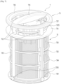
- the configuration of the filter assembly 7 will be described in detail with reference to FIGs. 7 and 8 .
- FIGs. 7 and 8 are views illustrating the filter assembly depicted in FIG. 1 .
- the filter assembly 7 may include the filter 73, which is inserted into the sump 4 in order to filter out foreign substances, and a handle member 71, which is coupled to the top of the filter 73.
- the handle member 71 is provided to facilitate mounting and demounting of the filter 73.
- the handle member 71 may be omitted as needed.
- the handle member 71 is separably coupled to the filter 73
- the present invention is not limited thereto.
- the handle member 71 and the filter 73 may be formed integrally with each other.
- the filter 73 may include a seat portion 731, which is seated on a portion of the sump cover 42 around the through-hole 421, the mesh member 733, which extends downwards from the seat portion 731 in order to remove foreign substances from the wash water stored in the storage unit 41, a support rib 732, which extends downwards from the seat portion 731 in order to support the mesh member 733, a support rim 735, which is provided at the lower end of the support rib 732 and is seated on the filter support portion 411, and a core member 737, which is provided on the seat portion 731 in order to remove foreign substances from the wash water that flows to the mesh member 733 from the region above the sump cover 42.
- the seat portion 731 may have therein an insertion hole 7311 for fixing the handle member 71.
- An extension rib 713 of the handle member 71 may be inserted into the insertion hole 7311.
- the shape and number of insertion holes 7311 may be set so as to correspond to the shape and number of extension ribs 713.
- the support rib 732 may be inserted into the sump 4, and may support the mesh member 733 so that the shape of the mesh member 733 can be maintained constant.
- a reinforcement ring 734 which is formed so as to intersect with the support rib 732. At this time, the number of support ribs 732 and the number of reinforcement rings 734 may be set properly depending on the size and material of the mesh member 733.
- the support rim 735 may be in contact with the filter support portion 411 of the sump 4, and may support the filter 73. That is, the filter 73 may be securely fixed inside the sump 4 in a manner such that the seat portion 731 and the support rim 735 are in contact with the sump cover 42 and the filter support portion 411, respectively. Accordingly, even when wash water moves inside the sump 4, the filter 73 may be prevented from being moved.
- the support rim 735 may be provided at the bottom or the side portion thereof with a fastening member.
- the filter support portion 411 may be provided with a fastening hole (not shown) having therein threads, and the fastening member, which is inserted into the fastening hole, may be provided at the bottom of the support rim 735.
- the fastening member may also have threads formed in the outer surface thereof. The fastening member may be inserted into the fastening hole and may be rotated so as to be securely engaged with the fastening hole. Accordingly, it is possible to fix the filter 73 to the sump 4 more securely.
- the mesh member 733 may be mounted between the seat portion 731 and the support rim 735 and may remove foreign substances from wash water. Since the mesh member 733 is mounted in a cylindrical shape along the support rib 732 and the reinforcement ring 734, the top and bottom of the mesh member 733 may be open. The top of the mesh member 733 may be covered with the core member 737, and the bottom of the mesh member 733 may communicate with the lower storage portion 415. This is illustrated in FIG. 1 .
- the wash water that is supplied into the filter 73 through the core member 737 and the circulation passage 475 may pass through the mesh member 733 in the direction indicated by the arrow F2. Accordingly, foreign substances present in the wash water may be caught on the inner circumferential surface of the mesh member 733, and the wash water, from which foreign substances have been removed, may be supplied to the spray arm 6 through the wash pump 45.
- the wash water sprayed from the spray arm 6 may be introduced into the storage unit 41 through the core member 737, and may also be introduced into the storage unit 41 through the collection holes 423 formed in the sump cover 42.
- the wash water may be introduced into the upper storage portion 413.
- the wash water introduced into the upper storage portion 413 may pass through the mesh member 733 in the direction indicated by the arrow F1, and foreign substances present in the wash water may collect on the outer circumferential surface of the mesh member 733.
- the core member 737 may cover the top of the mesh member 733 and may remove foreign substances from wash water.
- the core member 737 may include a core 7371 provided above the seat portion 731 and a plurality of ribs interconnecting the core 7371 and the seat portion 731.
- the ribs may include radial ribs 7373 and reinforcement ribs 7375, which intersect with each other.
- the core 7371, the radial ribs 7373 and the reinforcement ribs 7375 may define first and second holes 7376 and 7378 therebetween, which communicate with the interior of the filter 73. Wash water may be introduced into the filter 73 through the first and second holes 7376 and 7378. At this time, stick-type foreign substances such as toothpicks or the like may be filtered out.
- the core 7371 may have a guide hole 7379 formed in the top thereof, into which a guide rib 717 of the handle member 71 is fitted.
- the handle member 71 may include a ring-shaped body 711, a plurality of extension ribs 713, which extend downwards from the body 711 and are coupled to the filter 73, and a handle 715, which is formed across the body 711.
- the handle member 71 may be separably coupled to the filter 73. A user can insert the filter 73 into the sump 4 or take the filter 73 out of the sump 4 while grabbing the handle 715.
- each of the extension ribs 713 may be inserted into the insertion hole 7311 formed in the seat portion 731 of the filter 73.
- the extension rib 713 may be provided at the lower end thereof with a hook 714.
- the hook 714 may include an inclined surface 7141, which extends at an incline from the lower end of the extension rib 713 toward the center of the body 711, and a latching surface 7143.
- the latching surface 7143 comes into contact with the bottom surface of the seat portion 731. Accordingly, the extension rib 713 may be fixed on the seat portion 731.
- the body 711 may be provided with gap-maintaining protrusions 712.
- the gap-maintaining protrusions 712 protrude from the bottom surface of the body 711.
- the gap-maintaining protrusions 712 may come into contact with the top surface of the seat portion 731, thereby preventing the extension rib 713 from being inserted into the insertion hole 7311 beyond a predetermined depth.
- the handle 715 may be provided at the bottom surface thereof with the guide rib 717, which guides the coupling of the handle member 71 to the filter 73.
- the guide rib 717 may be inserted into the guide hole 7379 formed in the core member 737, whereby the handle member 71 can be coupled to the filter 73 in a correct direction.
- the dishwasher 1 is capable of diverting some or all of the wash water that is supplied from the wash pump 45 to the sump 4.
- the diverted wash water is supplied to the interior of the filter 73, whereby foreign substances present in the wash water are filtered out inside the filter 73.
- the diverted wash water passes through the filter 73, it can separate foreign substances from the outer surface of the filter 73. Accordingly, it is possible to prevent an object to be washed from being recontaminated with foreign substances present in wash water and to prevent the filter 73 from being blocked by foreign substances present in wash water.
- FIG. 9 is a flowchart for explaining a method of controlling the dishwasher depicted in FIG. 1 .
- the course may include at least one selected from among a preliminary washing process (S200), a washing process (S300), a rinsing process (S400), a heating-rinsing process (S500), a drying process (S600), and combinations thereof.
- a first course may be set to include the washing process and the rinsing process
- a second course may be set to include the preliminary washing process, the washing process, the rinsing process, the heating-rinsing process, and the drying process.
- the preliminary washing process may be a process of spraying water toward an object to be washed that is accommodated in the washing compartment 21 and of soaking the same so as to easily remove foreign substances from the object to be washed.
- the washing process may be a process of removing foreign substances from the object to be washed by spraying water and detergent toward the same.
- the rinsing process may be a process of removing foreign substances and detergent remaining on the object to be washed by spraying water toward the same.
- a rinsing agent may be sprayed along with water in order to disinfect the object to be washed.
- the rinsing agent may serve to weaken the surface tension of the water on the surface of the object to be washed, thereby making the water run down easily and consequently shortening the time taken to dry the object to be washed.
- the heating-rinsing process may be a process of heating the object to be washed by spraying water that was heated to a predetermined temperature toward the same so as to shorten the time taken to dry the object to be washed and to disinfect the same.
- the drying process may be a process of removing moisture from the surface of the object to be washed.
- the object to be washed may be dried passively.
- a drying fan (not shown) may be operated in order to discharge the air in the tub 2 to the outside, thereby shortening the drying time.
- the option may be the operating conditions under which each process of the selected course is operated.
- the operating conditions may be information about the temperature of water that is supplied to the object to be washed in the heating-rinsing process, an operating time of the drying fan in the drying process, the number of repetitions of each process, or the like.
- information about the most-recently performed course and related options may be loaded, or information about the course that has been performed most frequently during a predetermined period and related options may be loaded.
- a user may directly input information about the course and the option.
- the loading type may be set variously depending on the user's selection.
- At least one of the preliminary washing process (S200), the washing process (S300), the rinsing process (S400), the heating-rinsing process (S500), or the drying process (S600) is performed.
- wash water may be sprayed from the spray arm 6.
- the sprayed wash water may collect in the sump 4, and foreign substances, which were removed from the object to be washed, may be included in the collected wash water.
- the present invention is capable of removing foreign substances present in wash water by diverting a portion of sprayed wash water to the interior of the filter 73 and of removing foreign substances accumulated on the outer circumferential surface of the filter 73 by diverting all of wash water stored in the sump 4 to the interior of the filter 73 after the process is completed. Therefore, the present invention can be applied in the same or a similar way to every process in which the spraying of wash water is performed.
- washing process (S300), to which the present invention is applied will now be described in detail with reference to FIGs. 10 to 12 .
- the present invention should not be construed as being applied only to the washing process (S300).
- the present invention can be applied in the same or a similar way to every process in which wash water is sprayed toward an object to be washed.
- FIG. 10 is a flowchart showing the washing process of FIG. 9 .
- FIG. 11 is a flowchart showing a dish-washing step of FIG. 10 .
- FIG. 12 is a flowchart showing a filter-washing step of FIG. 10 .
- the water supply unit 43 supplies water to the interior of the sump 4 (S310). At this time, detergent or the like may be supplied along with the water in order to improve washing performance.
- wash water stored in the sump 4 (S320).
- the wash water in the storage unit 41 is supplied to the flow-switching unit 46 by operating the wash pump 45 (S321).
- the flow-switching unit 46 may selectively open or close the first supply passage 471 and the second supply passage 473 according to the selected option and may supply the wash water to the spray arm 6 through the opened passage (S322). If the first supply passage 471 is opened, the wash water may be supplied to the lower spray arm 61. If the second supply passage 473 is opened, the wash water may be supplied to the upper spray arm 63 and the top nozzle 65.
- the wash water supplied to the spray arm 6 is sprayed toward dishes contained in the containing unit 5.
- the sprayed wash water may collide with the dishes, may fall to the sump cover 42, and may collect in the upper storage portion 413 through the through-hole 421 and the collection holes 423.
- the wash water introduced into the through-hole 421 may collect in the interior of the filter 73 through the core member 737, and the wash water introduced into the collection holes 423 may collect in the exterior of the filter 73.
- the interior of the filter 73 is a region that is contiguous with the inner circumferential surface of the mesh member 733
- the exterior of the filter 73 is a region that is contiguous with the outer circumferential surface of the mesh member 733.
- the collected wash water may be again sprayed toward the dishes via the wash pump 45 and the spray arm 6 in that order. Through this circulation mechanism, wash water may be consistently sprayed toward the dishes.
- the wash pump 45 may be connected to the upper storage portion 413. Therefore, the wash water stored in the interior of the filter 73 may be moved to the exterior of the filter 73 in the direction indicated by the arrow F2, and may then be supplied to the wash pump 45. At this time, since the wash water passes through the mesh member 733 of the filter 73, foreign substances present in the wash water may collect on the inner circumferential surface of the mesh member 733.
- the wash water stored in the exterior of the filter 73 may be directly introduced into the wash pump 45 without passing through the mesh member 733.
- the wash water, in which foreign substances are included, may be sprayed toward the dishes through the spray arm 6.
- a portion of the wash water that is supplied to the spray arm 6 is diverted to the interior of the filter 73, thereby removing foreign substances from the wash water (S323).
- the flow-switching unit 46 may be controlled so as to open the circulation passage 475.
- the flow-switching plate 461 may be rotated to the location shown in FIG. 6(a) by operating the flow-switching motor 463 so as to open the circulation passage 475.
- the circulation passage 475 is connected to the lower storage portion 415, which communicates with the interior of the filter 73. Therefore, the wash water supplied through the circulation passage 475 may pass through the mesh member 733 of the filter 73 in the direction indicated by the arrow F2, and foreign substances present in the wash water may collect on the inner circumferential surface of the filter 73. If this circulation is repeated while the wash water is sprayed, foreign substances present in the wash water may collect on the inner circumferential surface of the filter 73. Accordingly, the wash water, from which foreign substances have been removed, may be supplied to the spray arm 6, thereby preventing recontamination of the dishes.
- the amount of wash water that is diverted to the interior of the filter 73 may be adjusted variously as needed.
- a sensor (not shown) for measuring the contamination of wash water is mounted in the sump 4, and the amount of wash water that is diverted is controlled depending on the degree of contamination of the wash water. Particularly, when the contamination of wash water is severe, the supply of wash water to the spray arm 6 may be stopped for a predetermined time period, and all of the wash water that is introduced into the wash pump 45 may be diverted through the circulation passage 475.
- the wash water stored in the storage unit 41 is discharged outside. At this time, foreign substances present in the wash water are also discharged outside along with the wash water. However, as shown in FIG. 1 , because the lower storage portion 415, to which the drain passage 443 is connected, communicates with the interior of the filter 73, foreign substances present in the exterior of the filter 73 may not be discharged along with the wash water. That is, when the drain pump 441 is operated, the wash water stored in the exterior of the filter 73 moves to the drain passage 443 in the direction indicated by the arrow F1, and at this time, foreign substances present in the wash water may collect on the outer circumferential surface of the mesh member 733.
- the foreign substances collected on the outer circumferential surface of the mesh member 733 may not be discharged outside and may remain inside the sump 4. This may be a cause of recontamination of the dishes in the rinsing process (S300) that is subsequently performed.
- the filter 73 may be blocked, or may not perform its role normally due to the foreign substances accumulated on the mesh member 733.
- the wash pump 45 is operated (S331), and all of the wash water stored in the storage unit 41 is diverted to the interior of the filter 73 (S332).
- the flow-switching plate 461 is moved to the location shown in FIG. 6(b) in order to open only the circulation passage 475. Since the first and second supply passages 471 and 473 are closed, the wash water is not supplied to the spray arm 6, and all of the wash water introduced into the wash pump 45 moves to the lower storage portion 415 through the circulation passage 475.
- the wash water introduced through the circulation passage 475 passes through the mesh member 733 of the filter 73 in the direction indicated by the arrow F2, and foreign substances present in the wash water are collected on the inner circumferential surface of the filter 73.
- the wash pump 45 is consistently operated for a predetermined time period, and thus most foreign substances present in the wash water are collected on the inner circumferential surface of the filter 73.
- the wash water moves in the direction indicated by the arrow F2.
- the wash water collides with the mesh member 733 of the filter 73.
- the force generated by this collision separates foreign substances from the outer circumferential surface of the mesh member 733.
- the separated foreign substances collect inside the mesh member 733 after passing through the wash pump 45 and the circulation passage 475, and are then discharged outside in the draining step (S340).
- the foreign-substance-collecting step (S330) may also have an effect of removing foreign substances accumulated on the outer circumferential surface of the mesh member 733.
- the wash pump 45 may be operated at a higher speed in the foreign-substance-collecting step (S330) than in the dish-washing step (S320).
- the second RPM may be greater than the first RPM.
- the reason for this is to increase the pressure at which the wash pump 45 sucks the wash water and consequently to remove foreign substances adhering to the outer circumferential surface of the mesh member 733 more easily. In this case, it is possible to enhance an effect of removing foreign substances accumulated on the outer circumferential surface of the mesh member 733 and to shorten the operating time of the foreign-substance-collecting step (S330).
- the operation of the wash pump 45 is stopped (S334) and the foreign-substance-collecting step (S330) is terminated. Subsequently, the drain pump 441 is operated in order to discharge the wash water and foreign substances outside the dishwasher 1 (S340).
- the method of controlling the dishwasher according to the present invention is capable of removing foreign substances from wash water by diverting some or all of the wash water that is supplied to the spray arm 6 to the interior of the filter 73. Accordingly, it is possible to prevent foreign substances separated from the dishes from being again sprayed along with the wash water toward the dishes.
- the present invention provides a dishwasher that is capable of removing foreign substances from wash water by diverting some or all of wash water that is supplied to a spray arm to the interior of a filter, and a method of controlling the dishwasher.
Landscapes
- Engineering & Computer Science (AREA)
- Water Supply & Treatment (AREA)
- Chemical & Material Sciences (AREA)
- Chemical Kinetics & Catalysis (AREA)
- Washing And Drying Of Tableware (AREA)
Claims (13)
- Verfahren zum Steuern eines Geschirrspülers (1), der Folgendes umfasst:einen Bottich (2) zum Aufnehmen von Geschirr,einen Sprüharm (6) zum Sprühen von Waschwasser auf das Geschirr,eine Wanne (4) zum Aufnehmen von Waschwasser,einen Filter (7), der in der Wanne (4) vorgesehen ist, um Fremdstoffe aus dem Waschwasser zu entfernen, undeine Waschpumpe (45) zum Zuführen von Waschwasser, das in der Wanne (4) aufgenommen ist, zum Sprüharm (6),wobei das Verfahren die folgenden Schritte umfasst:Waschen des Geschirrs, wobei das Waschen das Zuführen von Waschwasser zum Sprüharm (6) und das Umlenken wenigstens eines Teils des dem Sprüharm zugeführten Waschwassers ins Innere des Filters umfasst;Sammeln von Fremdstoffen, die im Waschwasser vorhanden sind, im Inneren des Filters (7) durch Umlenken des gesamten Waschwassers, das in die Waschpumpe (45) geleitet wird, ins Innere des Filters (7), wobei das Sammeln ausgeführt wird, nachdem das Waschen beendet worden ist; Abführen von Fremdstoffen, die im Inneren des Filters (7) gesammelt sind, zusammen mit dem Waschwasser nach außen,gekennzeichnet durch das Messen eines Verunreinigungsgrads des Waschwassers,wobei die Menge an Waschwasser, das beim Waschen ins Innere des Filters (7) umgelenkt wird, proportional zum gemessenen Verunreinigungsgrad des Waschwassers ist.
- Verfahren nach Anspruch 1, wobei dann, wenn der gemessene Verunreinigungsgrad des Waschwassers gleich einem zuvor festgelegten Wert oder höher ist, das gesamte Waschwasser, das in die Waschpumpe (45) geleitet wird, ins Innere des Filters (7) umgelenkt wird.
- Verfahren nach Anspruch 1, das ferner die folgenden Schritte umfasst:Messen eines Verunreinigungsgrads des Waschwassers,wobei das Sammeln ausgeführt wird, bis der gemessene Verunreinigungsgrad des Waschwassers gleich oder kleiner als ein zuvor festgelegter Wert ist.
- Verfahren nach Anspruch 1, wobei die Waschpumpe (45) beim Waschen mit einer ersten Drehzahl (RPM) betrieben wird, und
wobei die Waschpumpe (45) beim Sammeln mit einer zweiten Drehzahl betrieben wird, wobei die zweite Drehzahl höher als die erste Drehzahl ist. - Verfahren nach Anspruch 1, wobei das Zuführen, das Umlenken und das Sammeln in einem vorläufigen Waschverfahren zum Einweichen von Fremdstoffen durch Sprühen von Wasser auf das Geschirr, in einem Waschverfahren zum Entfernen von Fremdstoffen durch Sprühen von Wasser und Reinigungsmittel auf das Geschirr, in einem Spülverfahren zum Entfernen von Fremdstoffen und Reinigungsmittel, die auf dem Geschirr verblieben sind, durch Sprühen von Wasser auf das Geschirr, und/oder in einem Heiz-Spül-Verfahren zum Sprühen von erhitztem Wasser auf das Geschirr ausgeführt werden.
- Geschirrspüler (1), der Folgendes umfasst:einen Bottich (2), der konfiguriert ist, ein zu waschendes Objekt aufzunehmen;einen Sprüharm (6), der drehbar im Bottich (2) vorgesehen ist, wobei der Sprüharm (6) konfiguriert ist, Waschwasser zum zu waschenden Objekt zu sprühen;eine Wanne (4), die konfiguriert ist, Waschwasser aufzunehmen und Waschwasser, das in den Bottich (2) gesprüht wird, zu sammeln;einen Filter (7), der in der Wanne (4) abnehmbar montiert ist, wobei der Filter (7) konfiguriert ist, Fremdstoffe aus dem Waschwasser zu entfernen;eine Waschpumpe (45), die konfiguriert ist, Waschwasser, das in der Wanne (4) aufgenommen ist, dem Sprüharm (6) zuzuführen;einen Zufuhrdurchlass (471, 473), der konfiguriert ist, Waschwasser, das durch die Waschpumpe (45) zugeführt wird, zum Sprüharm (6) zu leiten; undeinen Umwälzdurchlass (475), der vom Zuführdurchlass (471, 473) abzweigt und konfiguriert ist, wenigstens einen Teil des Waschwassers, das dem Sprüharm (6) durch die Waschpumpe (45) zugeführt wird, zur Wanne (4) umzulenken, wobei der Umwälzdurchlass (475) Waschwasser ins Innere des Filters (7) zuführt,gekennzeichnet durch einen Sensor zum Messen der Verunreinigung von Waschwasser, der in der Wanne (4) montiert ist, wobei die Menge an Waschwasser, die ins Innere des Filters (7) umgelenkt wird, proportional zum gemessenen Verunreinigungsgrad des Waschwassers ist.
- Geschirrspüler nach Anspruch 6, wobei der Filter (7) einen offenen Boden hat, und
wobei die Wanne (4) Folgendes umfasst:einen Filterträgerabschnitt (411), der konfiguriert ist, den Boden des Filters (7) zu tragen;einen unteren Aufnahmeabschnitt (415), der unter dem Filterträgerabschnitt (411) angeordnet ist, wobei der untere Aufnahmeabschnitt (415) mit dem Inneren des Filters (7) durch den offenen Boden des Filters (7) kommuniziert; undeinen oberen Aufnahmeabschnitt (413), der am Filterträgerabschnitt (411) angeordnet ist, wobei der obere Aufnahmeabschnitt (413) vom unteren Aufnahmeabschnitt (415) durch den Filterträgerabschnitt (411) getrennt ist und mit einer Außenseite des Filters (7) in Kontakt ist. - Geschirrspüler nach Anspruch 6, der ferner Folgendes umfasst:
eine Strömungsumschalteinheit (46), die konfiguriert ist, den Zufuhrdurchlass (471, 473) und den Umwälzdurchlass (475) wahlweise zu öffnen oder zu schließen. - Geschirrspüler nach Anspruch 8, wobei die Strömungsumschalteinheit (46) Folgendes umfasst:eine Strömungsumschaltplatte (461), die wenigstens eine Öffnung zum Öffnen des Zuführdurchlasses (471, 473) und des Umwälzdurchlasses (475) aufweist; undeinen Strömungsumschaltmotor, der konfiguriert ist, die Strömungsumschaltplatte (461) zu drehen, wobei der Zuführdurchlass (471, 473) und der Umwälzdurchlass (475) in Abhängigkeit von einer Drehung der Strömungsumschaltplatte (461) gleichzeitig oder wahlweise geöffnet werden.
- Geschirrspüler nach Anspruch 8, wobei der Filter (7) Folgendes umfasst:ein Siebelement (733), das sich durch eine Wannenabdeckung (42) in die Wanne (4) erstreckt und auf dem Filterträgerabschnitt (411) sitzt, wobei das Siebelement (733) konfiguriert ist, Fremdstoffe aus dem Waschwasser zu entfernen; undein Kernelement (737), das eine Oberseite des Siebelements (733) bedeckt, wobei das Kernelement (737) konfiguriert ist, Fremdstoffe aus Waschwasser zu entfernen, das von einem Bereich über der Wannenabdeckung (42) zum Siebelement (733) strömt.
- Geschirrspüler nach Anspruch 6, wobei der Filter (7) einen offenen Boden hat und sich zu einer Bodenfläche der Wanne (4) erstreckt.
- Geschirrspüler nach Anspruch 11, wobei der Umwälzdurchlass (475) durch die Bodenfläche der Wanne (4) verläuft und mit dem Inneren des Filters (7) kommuniziert.
- Geschirrspüler nach Anspruch 11, der ferner Folgendes umfasst:
eine Ablaufeinheit (44), die durch die Bodenfläche der Wanne (4) verläuft und mit dem Inneren des Filters (7) kommuniziert, wobei die Ablaufeinheit (44) konfiguriert ist, Waschwasser, das in der Wanne (4) aufgenommen ist, daraus abzuführen.
Applications Claiming Priority (2)
| Application Number | Priority Date | Filing Date | Title |
|---|---|---|---|
| KR1020170033621A KR20180106057A (ko) | 2017-03-17 | 2017-03-17 | 식기세척기 |
| PCT/KR2018/003035 WO2018169322A1 (en) | 2017-03-17 | 2018-03-15 | Dishwasher and method of controlling the same |
Publications (3)
| Publication Number | Publication Date |
|---|---|
| EP3595504A1 EP3595504A1 (de) | 2020-01-22 |
| EP3595504A4 EP3595504A4 (de) | 2020-12-23 |
| EP3595504B1 true EP3595504B1 (de) | 2024-12-11 |
Family
ID=63522317
Family Applications (1)
| Application Number | Title | Priority Date | Filing Date |
|---|---|---|---|
| EP18767984.0A Active EP3595504B1 (de) | 2017-03-17 | 2018-03-15 | Geschirrspülmaschine und verfahren zur steuerung davon |
Country Status (4)
| Country | Link |
|---|---|
| US (1) | US11330957B2 (de) |
| EP (1) | EP3595504B1 (de) |
| KR (1) | KR20180106057A (de) |
| WO (1) | WO2018169322A1 (de) |
Families Citing this family (4)
| Publication number | Priority date | Publication date | Assignee | Title |
|---|---|---|---|---|
| USD937506S1 (en) * | 2019-10-04 | 2021-11-30 | Whirlpool Corporation | Sprayer assembly |
| USD956372S1 (en) | 2019-11-26 | 2022-06-28 | Whirlpool Corporation | Spray arm for a dish treating appliance |
| KR20240002848A (ko) | 2022-06-30 | 2024-01-08 | 삼성전자주식회사 | 식기세척기 |
| KR20250120069A (ko) * | 2024-02-01 | 2025-08-08 | 삼성전자주식회사 | 식기세척기 |
Family Cites Families (21)
| Publication number | Priority date | Publication date | Assignee | Title |
|---|---|---|---|---|
| KR100269467B1 (ko) | 1998-06-22 | 2000-12-01 | 윤종용 | 일체형 펌프를 가진 식기세척기의 필터장치 |
| US6615853B2 (en) * | 2001-01-03 | 2003-09-09 | General Electric Company | Dishwasher fine filter pressure relief |
| US7472712B2 (en) * | 2003-09-05 | 2009-01-06 | Whirlpool Corporation | Dishwasher filter |
| US7350527B2 (en) | 2004-07-06 | 2008-04-01 | Whirlpool Corporation | Dishwasher filter system |
| KR100640870B1 (ko) | 2004-09-22 | 2006-11-02 | 엘지전자 주식회사 | 식기 세척기의 구동부 및 그 제어방법 |
| KR100617123B1 (ko) * | 2004-09-22 | 2006-08-30 | 엘지전자 주식회사 | 식기세척기의 구동부 |
| US20060237049A1 (en) * | 2005-04-25 | 2006-10-26 | Viking Range Corporation | Primary filter cleaning system for a dishwasher |
| US20060237050A1 (en) * | 2005-04-25 | 2006-10-26 | Viking Range Corporation | Dishwasher collection chamber filter cleaning system |
| US7695572B2 (en) * | 2005-05-31 | 2010-04-13 | Lg Electronics Inc. | Dishwasher and controlling method thereof |
| EP1897481B1 (de) * | 2006-09-08 | 2015-06-17 | Whirlpool Corporation | Haushaltwaschmaschine mit einem Biozidemittel in der Waschkammer. |
| US20080237154A1 (en) * | 2007-02-06 | 2008-10-02 | Electrolux Home Products, Inc. | Filter device for a dishwasher, and associated apparatus and method |
| US7909940B2 (en) * | 2007-05-30 | 2011-03-22 | Lg Electronics Inc. | Dish washing machine with steam generator and method of controlling same |
| KR101054435B1 (ko) | 2008-11-10 | 2011-08-05 | 엘지전자 주식회사 | 식기 세척기의 제어방법 |
| US9492052B2 (en) | 2009-12-25 | 2016-11-15 | Arcelik Anonim Sirketi | Dishwasher comprising a microfilter |
| US8973591B2 (en) * | 2011-06-08 | 2015-03-10 | General Electric Company | Dishwasher with a motor driven filter backflush system and associated backflush method |
| KR101812169B1 (ko) | 2011-06-14 | 2017-12-26 | 엘지전자 주식회사 | 식기세척기 |
| KR101871270B1 (ko) | 2011-12-19 | 2018-06-28 | 엘지전자 주식회사 | 식기세척기 및 그의 제어방법 |
| KR101938705B1 (ko) | 2011-12-20 | 2019-01-16 | 삼성전자주식회사 | 식기 세척기 및 그 제어 방법 |
| KR102042221B1 (ko) * | 2012-12-28 | 2019-11-07 | 엘지전자 주식회사 | 식기세척기 및 그 제어방법 |
| KR102391681B1 (ko) | 2015-07-21 | 2022-04-28 | 엘지전자 주식회사 | 식기세척기 |
| CN106551667B (zh) * | 2015-09-24 | 2019-10-25 | Lg电子株式会社 | 洗碗机 |
-
2017
- 2017-03-17 KR KR1020170033621A patent/KR20180106057A/ko not_active Ceased
-
2018
- 2018-03-15 US US16/495,031 patent/US11330957B2/en active Active
- 2018-03-15 EP EP18767984.0A patent/EP3595504B1/de active Active
- 2018-03-15 WO PCT/KR2018/003035 patent/WO2018169322A1/en not_active Ceased
Also Published As
| Publication number | Publication date |
|---|---|
| US20200008644A1 (en) | 2020-01-09 |
| KR20180106057A (ko) | 2018-10-01 |
| EP3595504A4 (de) | 2020-12-23 |
| WO2018169322A1 (en) | 2018-09-20 |
| EP3595504A1 (de) | 2020-01-22 |
| US11330957B2 (en) | 2022-05-17 |
Similar Documents
| Publication | Publication Date | Title |
|---|---|---|
| EP2236073B1 (de) | Geschirrspüler | |
| EP3595504B1 (de) | Geschirrspülmaschine und verfahren zur steuerung davon | |
| US7614408B2 (en) | Apparatus for controlling washing flow of dishwasher | |
| US8746261B2 (en) | Rotating drum filter for a dishwashing machine | |
| US20140299156A1 (en) | Rotary drum filter for a dishwashing machine | |
| US20120118336A1 (en) | Dishwasher with filter cleaning assembly | |
| US8221554B2 (en) | Filtering method and related dishwasher | |
| EP2671495A2 (de) | Drehfilter für einen Geschirrspüler | |
| US9642510B2 (en) | Dishwasher and control method thereof | |
| KR101245590B1 (ko) | 식기 세척기의 배수펌프 및 그를 이용한 식기세척기의 운전방법 | |
| US12016508B2 (en) | Dish washer and controlling method thereof | |
| KR102396042B1 (ko) | 식기세척기 | |
| KR102336985B1 (ko) | 식기세척기의 제어방법 | |
| US20150265129A1 (en) | Automatic dishwasher with pump assembly | |
| JP2025010306A (ja) | 制御方法 | |
| US12364384B2 (en) | Docking filter for a dishwasher appliance | |
| US7556050B2 (en) | Self-drainage preventing structure of dish washer | |
| KR20200084543A (ko) | 식기세척기의 제어방법 | |
| EP3324812B1 (de) | Geschirrspüler | |
| US20150083170A1 (en) | Dishwashing appliance and vent for dishwashing appliance | |
| US12232677B2 (en) | Filter cleaning assembly for a dishwasher appliance | |
| US20150107632A1 (en) | Progressive fine filtration for a dishwashing appliance | |
| JP2653254B2 (ja) | 食器洗浄機 | |
| CN119606280A (zh) | 餐具清洗机 | |
| CN118434341A (zh) | 包括流控制器组件的洗碗机 |
Legal Events
| Date | Code | Title | Description |
|---|---|---|---|
| STAA | Information on the status of an ep patent application or granted ep patent |
Free format text: STATUS: THE INTERNATIONAL PUBLICATION HAS BEEN MADE |
|
| PUAI | Public reference made under article 153(3) epc to a published international application that has entered the european phase |
Free format text: ORIGINAL CODE: 0009012 |
|
| STAA | Information on the status of an ep patent application or granted ep patent |
Free format text: STATUS: REQUEST FOR EXAMINATION WAS MADE |
|
| 17P | Request for examination filed |
Effective date: 20190916 |
|
| AK | Designated contracting states |
Kind code of ref document: A1 Designated state(s): AL AT BE BG CH CY CZ DE DK EE ES FI FR GB GR HR HU IE IS IT LI LT LU LV MC MK MT NL NO PL PT RO RS SE SI SK SM TR |
|
| AX | Request for extension of the european patent |
Extension state: BA ME |
|
| DAV | Request for validation of the european patent (deleted) | ||
| DAX | Request for extension of the european patent (deleted) | ||
| A4 | Supplementary search report drawn up and despatched |
Effective date: 20201125 |
|
| RIC1 | Information provided on ipc code assigned before grant |
Ipc: A47L 15/00 20060101ALI20201119BHEP Ipc: A47L 15/42 20060101AFI20201119BHEP |
|
| STAA | Information on the status of an ep patent application or granted ep patent |
Free format text: STATUS: EXAMINATION IS IN PROGRESS |
|
| 17Q | First examination report despatched |
Effective date: 20221206 |
|
| GRAP | Despatch of communication of intention to grant a patent |
Free format text: ORIGINAL CODE: EPIDOSNIGR1 |
|
| STAA | Information on the status of an ep patent application or granted ep patent |
Free format text: STATUS: GRANT OF PATENT IS INTENDED |
|
| INTG | Intention to grant announced |
Effective date: 20240722 |
|
| GRAS | Grant fee paid |
Free format text: ORIGINAL CODE: EPIDOSNIGR3 |
|
| GRAA | (expected) grant |
Free format text: ORIGINAL CODE: 0009210 |
|
| STAA | Information on the status of an ep patent application or granted ep patent |
Free format text: STATUS: THE PATENT HAS BEEN GRANTED |
|
| AK | Designated contracting states |
Kind code of ref document: B1 Designated state(s): AL AT BE BG CH CY CZ DE DK EE ES FI FR GB GR HR HU IE IS IT LI LT LU LV MC MK MT NL NO PL PT RO RS SE SI SK SM TR |
|
| REG | Reference to a national code |
Ref country code: GB Ref legal event code: FG4D |
|
| REG | Reference to a national code |
Ref country code: CH Ref legal event code: EP |
|
| REG | Reference to a national code |
Ref country code: DE Ref legal event code: R096 Ref document number: 602018077512 Country of ref document: DE |
|
| REG | Reference to a national code |
Ref country code: IE Ref legal event code: FG4D |
|
| REG | Reference to a national code |
Ref country code: LT Ref legal event code: MG9D |
|
| PG25 | Lapsed in a contracting state [announced via postgrant information from national office to epo] |
Ref country code: HR Free format text: LAPSE BECAUSE OF FAILURE TO SUBMIT A TRANSLATION OF THE DESCRIPTION OR TO PAY THE FEE WITHIN THE PRESCRIBED TIME-LIMIT Effective date: 20241211 |
|
| PGFP | Annual fee paid to national office [announced via postgrant information from national office to epo] |
Ref country code: DE Payment date: 20250205 Year of fee payment: 8 |
|
| PG25 | Lapsed in a contracting state [announced via postgrant information from national office to epo] |
Ref country code: FI Free format text: LAPSE BECAUSE OF FAILURE TO SUBMIT A TRANSLATION OF THE DESCRIPTION OR TO PAY THE FEE WITHIN THE PRESCRIBED TIME-LIMIT Effective date: 20241211 |
|
| PG25 | Lapsed in a contracting state [announced via postgrant information from national office to epo] |
Ref country code: BG Free format text: LAPSE BECAUSE OF FAILURE TO SUBMIT A TRANSLATION OF THE DESCRIPTION OR TO PAY THE FEE WITHIN THE PRESCRIBED TIME-LIMIT Effective date: 20241211 |
|
| REG | Reference to a national code |
Ref country code: NL Ref legal event code: MP Effective date: 20241211 |
|
| PG25 | Lapsed in a contracting state [announced via postgrant information from national office to epo] |
Ref country code: ES Free format text: LAPSE BECAUSE OF FAILURE TO SUBMIT A TRANSLATION OF THE DESCRIPTION OR TO PAY THE FEE WITHIN THE PRESCRIBED TIME-LIMIT Effective date: 20241211 |
|
| PG25 | Lapsed in a contracting state [announced via postgrant information from national office to epo] |
Ref country code: NO Free format text: LAPSE BECAUSE OF FAILURE TO SUBMIT A TRANSLATION OF THE DESCRIPTION OR TO PAY THE FEE WITHIN THE PRESCRIBED TIME-LIMIT Effective date: 20250311 |
|
| PG25 | Lapsed in a contracting state [announced via postgrant information from national office to epo] |
Ref country code: LV Free format text: LAPSE BECAUSE OF FAILURE TO SUBMIT A TRANSLATION OF THE DESCRIPTION OR TO PAY THE FEE WITHIN THE PRESCRIBED TIME-LIMIT Effective date: 20241211 Ref country code: GR Free format text: LAPSE BECAUSE OF FAILURE TO SUBMIT A TRANSLATION OF THE DESCRIPTION OR TO PAY THE FEE WITHIN THE PRESCRIBED TIME-LIMIT Effective date: 20250312 |
|
| PGFP | Annual fee paid to national office [announced via postgrant information from national office to epo] |
Ref country code: IT Payment date: 20250206 Year of fee payment: 8 |
|
| PG25 | Lapsed in a contracting state [announced via postgrant information from national office to epo] |
Ref country code: RS Free format text: LAPSE BECAUSE OF FAILURE TO SUBMIT A TRANSLATION OF THE DESCRIPTION OR TO PAY THE FEE WITHIN THE PRESCRIBED TIME-LIMIT Effective date: 20250311 |
|
| PG25 | Lapsed in a contracting state [announced via postgrant information from national office to epo] |
Ref country code: NL Free format text: LAPSE BECAUSE OF FAILURE TO SUBMIT A TRANSLATION OF THE DESCRIPTION OR TO PAY THE FEE WITHIN THE PRESCRIBED TIME-LIMIT Effective date: 20241211 |
|
| REG | Reference to a national code |
Ref country code: AT Ref legal event code: MK05 Ref document number: 1749675 Country of ref document: AT Kind code of ref document: T Effective date: 20241211 |
|
| PG25 | Lapsed in a contracting state [announced via postgrant information from national office to epo] |
Ref country code: SM Free format text: LAPSE BECAUSE OF FAILURE TO SUBMIT A TRANSLATION OF THE DESCRIPTION OR TO PAY THE FEE WITHIN THE PRESCRIBED TIME-LIMIT Effective date: 20241211 |
|
| PG25 | Lapsed in a contracting state [announced via postgrant information from national office to epo] |
Ref country code: PL Free format text: LAPSE BECAUSE OF FAILURE TO SUBMIT A TRANSLATION OF THE DESCRIPTION OR TO PAY THE FEE WITHIN THE PRESCRIBED TIME-LIMIT Effective date: 20241211 |
|
| PG25 | Lapsed in a contracting state [announced via postgrant information from national office to epo] |
Ref country code: IS Free format text: LAPSE BECAUSE OF FAILURE TO SUBMIT A TRANSLATION OF THE DESCRIPTION OR TO PAY THE FEE WITHIN THE PRESCRIBED TIME-LIMIT Effective date: 20250411 |
|
| PG25 | Lapsed in a contracting state [announced via postgrant information from national office to epo] |
Ref country code: PT Free format text: LAPSE BECAUSE OF FAILURE TO SUBMIT A TRANSLATION OF THE DESCRIPTION OR TO PAY THE FEE WITHIN THE PRESCRIBED TIME-LIMIT Effective date: 20250411 |
|
| PG25 | Lapsed in a contracting state [announced via postgrant information from national office to epo] |
Ref country code: EE Free format text: LAPSE BECAUSE OF FAILURE TO SUBMIT A TRANSLATION OF THE DESCRIPTION OR TO PAY THE FEE WITHIN THE PRESCRIBED TIME-LIMIT Effective date: 20241211 |
|
| PG25 | Lapsed in a contracting state [announced via postgrant information from national office to epo] |
Ref country code: AT Free format text: LAPSE BECAUSE OF FAILURE TO SUBMIT A TRANSLATION OF THE DESCRIPTION OR TO PAY THE FEE WITHIN THE PRESCRIBED TIME-LIMIT Effective date: 20241211 Ref country code: RO Free format text: LAPSE BECAUSE OF FAILURE TO SUBMIT A TRANSLATION OF THE DESCRIPTION OR TO PAY THE FEE WITHIN THE PRESCRIBED TIME-LIMIT Effective date: 20241211 |
|
| PG25 | Lapsed in a contracting state [announced via postgrant information from national office to epo] |
Ref country code: SK Free format text: LAPSE BECAUSE OF FAILURE TO SUBMIT A TRANSLATION OF THE DESCRIPTION OR TO PAY THE FEE WITHIN THE PRESCRIBED TIME-LIMIT Effective date: 20241211 |
|
| PG25 | Lapsed in a contracting state [announced via postgrant information from national office to epo] |
Ref country code: CZ Free format text: LAPSE BECAUSE OF FAILURE TO SUBMIT A TRANSLATION OF THE DESCRIPTION OR TO PAY THE FEE WITHIN THE PRESCRIBED TIME-LIMIT Effective date: 20241211 |
|
| PG25 | Lapsed in a contracting state [announced via postgrant information from national office to epo] |
Ref country code: SE Free format text: LAPSE BECAUSE OF FAILURE TO SUBMIT A TRANSLATION OF THE DESCRIPTION OR TO PAY THE FEE WITHIN THE PRESCRIBED TIME-LIMIT Effective date: 20241211 |
|
| REG | Reference to a national code |
Ref country code: DE Ref legal event code: R097 Ref document number: 602018077512 Country of ref document: DE |
|
| PG25 | Lapsed in a contracting state [announced via postgrant information from national office to epo] |
Ref country code: DK Free format text: LAPSE BECAUSE OF FAILURE TO SUBMIT A TRANSLATION OF THE DESCRIPTION OR TO PAY THE FEE WITHIN THE PRESCRIBED TIME-LIMIT Effective date: 20241211 |
|
| PG25 | Lapsed in a contracting state [announced via postgrant information from national office to epo] |
Ref country code: MC Free format text: LAPSE BECAUSE OF FAILURE TO SUBMIT A TRANSLATION OF THE DESCRIPTION OR TO PAY THE FEE WITHIN THE PRESCRIBED TIME-LIMIT Effective date: 20241211 |
|
| PLBE | No opposition filed within time limit |
Free format text: ORIGINAL CODE: 0009261 |
|
| STAA | Information on the status of an ep patent application or granted ep patent |
Free format text: STATUS: NO OPPOSITION FILED WITHIN TIME LIMIT |
|
| REG | Reference to a national code |
Ref country code: CH Ref legal event code: L10 Free format text: ST27 STATUS EVENT CODE: U-0-0-L10-L00 (AS PROVIDED BY THE NATIONAL OFFICE) Effective date: 20251022 |
|
| REG | Reference to a national code |
Ref country code: CH Ref legal event code: H13 Free format text: ST27 STATUS EVENT CODE: U-0-0-H10-H13 (AS PROVIDED BY THE NATIONAL OFFICE) Effective date: 20251024 |
|
| PG25 | Lapsed in a contracting state [announced via postgrant information from national office to epo] |
Ref country code: LU Free format text: LAPSE BECAUSE OF NON-PAYMENT OF DUE FEES Effective date: 20250315 |
|
| 26N | No opposition filed |
Effective date: 20250912 |
|
| GBPC | Gb: european patent ceased through non-payment of renewal fee |
Effective date: 20250315 |
|
| REG | Reference to a national code |
Ref country code: BE Ref legal event code: MM Effective date: 20250331 |
|
| PG25 | Lapsed in a contracting state [announced via postgrant information from national office to epo] |
Ref country code: GB Free format text: LAPSE BECAUSE OF NON-PAYMENT OF DUE FEES Effective date: 20250315 |
|
| PG25 | Lapsed in a contracting state [announced via postgrant information from national office to epo] |
Ref country code: FR Free format text: LAPSE BECAUSE OF NON-PAYMENT OF DUE FEES Effective date: 20250331 |
|
| PG25 | Lapsed in a contracting state [announced via postgrant information from national office to epo] |
Ref country code: BE Free format text: LAPSE BECAUSE OF NON-PAYMENT OF DUE FEES Effective date: 20250331 |
|
| PG25 | Lapsed in a contracting state [announced via postgrant information from national office to epo] |
Ref country code: CH Free format text: LAPSE BECAUSE OF NON-PAYMENT OF DUE FEES Effective date: 20250331 |
|
| PG25 | Lapsed in a contracting state [announced via postgrant information from national office to epo] |
Ref country code: IE Free format text: LAPSE BECAUSE OF NON-PAYMENT OF DUE FEES Effective date: 20250315 |