EP3595484B1 - Caster assembly for a luggage case - Google Patents
Caster assembly for a luggage case Download PDFInfo
- Publication number
- EP3595484B1 EP3595484B1 EP18767063.3A EP18767063A EP3595484B1 EP 3595484 B1 EP3595484 B1 EP 3595484B1 EP 18767063 A EP18767063 A EP 18767063A EP 3595484 B1 EP3595484 B1 EP 3595484B1
- Authority
- EP
- European Patent Office
- Prior art keywords
- bottom part
- assembly
- corner bottom
- adapter
- luggage case
- Prior art date
- Legal status (The legal status is an assumption and is not a legal conclusion. Google has not performed a legal analysis and makes no representation as to the accuracy of the status listed.)
- Active
Links
Images




Classifications
-
- A—HUMAN NECESSITIES
- A45—HAND OR TRAVELLING ARTICLES
- A45C—PURSES; LUGGAGE; HAND CARRIED BAGS
- A45C5/00—Rigid or semi-rigid luggage
- A45C5/14—Rigid or semi-rigid luggage with built-in rolling means
- A45C5/143—Rigid or semi-rigid luggage with built-in rolling means detachable
-
- A—HUMAN NECESSITIES
- A45—HAND OR TRAVELLING ARTICLES
- A45C—PURSES; LUGGAGE; HAND CARRIED BAGS
- A45C5/00—Rigid or semi-rigid luggage
- A45C5/14—Rigid or semi-rigid luggage with built-in rolling means
-
- B—PERFORMING OPERATIONS; TRANSPORTING
- B60—VEHICLES IN GENERAL
- B60B—VEHICLE WHEELS; CASTORS; AXLES FOR WHEELS OR CASTORS; INCREASING WHEEL ADHESION
- B60B33/00—Castors in general ; Anti-clogging castors
- B60B33/0002—Castors in general ; Anti-clogging castors assembling to the object, e.g. furniture
- B60B33/0005—Castors in general ; Anti-clogging castors assembling to the object, e.g. furniture characterised by mounting method
- B60B33/0007—Castors in general ; Anti-clogging castors assembling to the object, e.g. furniture characterised by mounting method by screwing
-
- B—PERFORMING OPERATIONS; TRANSPORTING
- B60—VEHICLES IN GENERAL
- B60B—VEHICLE WHEELS; CASTORS; AXLES FOR WHEELS OR CASTORS; INCREASING WHEEL ADHESION
- B60B33/00—Castors in general ; Anti-clogging castors
- B60B33/0002—Castors in general ; Anti-clogging castors assembling to the object, e.g. furniture
- B60B33/0015—Castors in general ; Anti-clogging castors assembling to the object, e.g. furniture characterised by adaptations made to castor
- B60B33/0023—Castors in general ; Anti-clogging castors assembling to the object, e.g. furniture characterised by adaptations made to castor in the form of specific adaptations to the form of the object
-
- B—PERFORMING OPERATIONS; TRANSPORTING
- B60—VEHICLES IN GENERAL
- B60B—VEHICLE WHEELS; CASTORS; AXLES FOR WHEELS OR CASTORS; INCREASING WHEEL ADHESION
- B60B2200/00—Type of product being used or applied
- B60B2200/40—Articles of daily use
Definitions
- the present invention concerns an assembly for securing luggage case casters, skis, and other transportation aids of a luggage case acting against a ground.
- An adapter is formed of a separate holder and has coupling means. Said coupling means is/are co-operatable with supplementary coupling element/elements situated on a caster holder for a caster housing or another holder for another transportation aid.
- the adapter is arranged receivable in and/or is connectable with a separate or integrated corner bottom part of the luggage case in question, said adapter being arranged interlockable and connectable with surrounding caster holder/holder as well as corner bottom part.
- Fastening and securing of, e.g., casters of suitcases is provided using varying fastening parts having fitting sizes for intended casters, etc., and luggage cases.
- numerous parts are required to get the casters, etc., to fit to the correct luggage case and with the correct desired sizes of the same.
- vacuum forming of luggage cases manufactured from plastic material there are problems to provide means for securing to the proper shell of the luggage cases in vacuum forming. This is however facilitated in injection moulding of luggage cases.
- WO 2014/117305 A1 relates to an assembly according to the preamble of claim 1.
- the main object of the present invention is primarily to solve said problems to be able to, by few parts, fasten casters, etc., to manufactured luggage cases so that the means therefor can be used in any one of the luggage cases desired, but also in luggage cases manufactured by vacuum forming.
- Another object is also to provide a robust fixing where it is relatively easy to replace casters or another transportation aid.
- the adapter and the caster holder/holder have paired, essentially parallel grooves at mutual distances from each other.
- the grooves are male-shaped and female-shaped, respectively, on common part (the holder and the caster housing, respectively).
- the caster housing that is provided with female-shaped grooves and the caster housing that is provided with male-shaped grooves, respectively also has transverse female-shaped and male-shaped, respectively, end groove in the two parts, which transverse end grooves are co-operatable with each other when the parts are in entirely inserted position.
- the adapter is preferably receivable with the main part thereof in a congruent recess of the corner bottom part.
- the corner bottom part is preferably formed of a separate part or consists of an integrated corner part of a luggage case in question.
- the openings are situated at mutual distances from each other, along the circumference of the corner bottom part and of the adapter, respectively.
- the parts of the assembly consist of plastic material, such as polypropylene, ABS, and/or nylon.
- the corner bottom part has a border which extends along approximately half the circumference portion of the corner bottom part.
- the border extends in an arched manner along the corner bottom part on elevated level from the primarily flat reception portion of the same as well as from a lower level at the respective end portions of the body.
- An assembly 1 for the securing of casters 2, skis, runners, and other suitable and possible transportation aids acting against a ground comprises an adapter 6 which is formed of a separate part 7 and which has one or more coupling means 50.
- Said coupling means 50 is/are arranged co-operatable with one or more supplementary coupling element/elements 52 situated on a caster holder 51 for a caster housing 4 or another holder for another transportation aid.
- a caster housing 4 arranged on a suitcase 3 comprises a rotatable mounting 14 intended for said luggage case casters 2.
- An adapter 6 is formed of an intermediate holder 7 which is situated between a said caster housing 4 and a suitcase 3 and which is interlockable with a corner bottom part 8.
- a said adapter 6 is arranged to allow to be used for the interlocking of identical caster housings 4, etc., intended for different luggage case types, and/or luggage case sizes, or on suitcases 3 manufactured by vacuum forming.
- Said corner bottom part 8 is shape-adapted to the integrated corner part 3A of an intended luggage case and which has at least one arc-shaped end portion, preferably two arc-shaped end portions 9, 10.
- the corner bottom part 8 has a plurality of recesses/openings 11 on the respective upper and under side 8A, 8B thereof and which are shape-adapted for the receipt of upwardly projecting pegs 12 of the holder 7 and cylindrical feet 13 receivable between the luggage case 3 and the corner bottom part 8 for the bolting of the assembly by fixing screw 18, respectively.
- Said recesses/openings 11 are situated at mutual distances from each other, along the circumference and upper part 15 of the corner bottom part 8 and of the holder 7, respectively, and the pegs 12 as well as the feet 13 have screw holes 16, 17 for the receipt of the fixing screws 18 for said feet 13 and pegs 12.
- corner bottom part 8 is arranged to be boltable to said holder 7 by means of separate screws 19, which are received in holes 54, 55 in the corner bottom part 8 and in the holder 7, respectively.
- Said corner bottom part 8 has at the top a border 22 which extends along approximately half the circumference portion of the body for the co-operation with the corner 3A of a said interlockable luggage case 3.
- This border 22 extends in an arched manner along the corner bottom part 8 on elevated level 24 from the principal flat reception portion 23 of the same as well as from a lower level 25 at the respective end portions 9, 10 of the body.
- an assembly 1 can be utilized by the fact that the adapter 6 thereof can be interlocked with an intended corner bottom part 8 of correct size to fit the luggage case 3 to the same, between the luggage case 3 and the holder 7.
- caster housings 4 of one and the same kind and size can be utilized for several different sizes of luggage cases and for luggage cases of different types.
- the holder 7, which is arranged to be placed between caster housing 4 and intended corner bottom part 8, is arranged to fit to be possible to be interlocked with desired suitable mating corner bottom part 8.
- the parts are interlocked by the intended screws being arranged to screw together the above-mentioned parts with each other in order of priority as counted from below.
- the holder 7 with the paired coupling means 50 thereof is arranged to be possible to be interlocked with the supplementary coupling elements 52 likewise arranged in pairs, which are arranged on a caster housing 4 or on another holder for another suitable transportation aid, e.g. skis or runners if the luggage case is desired to be provided with such ones for pulling purpose, by being possible to be displaced in relation to each other in the longitudinal direction 60 of the coupling means.
- Coupling means 50 and coupling elements 52 are preferably formed of paired, essentially parallel grooves 29, 28 at mutual distances A, B from each other, which are male-shaped and female-shaped, respectively, on common part.
- the adapter 6 is arranged receivable in and/or connectable with a separate or integrated corner bottom part 8 for a luggage case 3 in question. In doing so, said adapter 6 is arranged interlockable and connectable with surrounding caster holder 51 as well as corner bottom part 8.
- the part that is provided with female-shaped grooves and the part that is provided with male-shaped grooves, respectively also has transverse female-shaped and transverse male-shaped, respectively, end grooves 26, 27 in the two parts. These transverse end grooves are co-operatable with each other when caster housing 4 and the holder 7 are in entirely inserted position, as is shown in Fig. 1 .
- the adapter 6 has a plurality of pegs 12 projecting perpendicularly from the upper part 15 of the holder 7, which pegs 12 are receivable in mating recesses 11 of the corner part 8 and which pegs 12 form receivers for fixing screws 18 in assembled parts.
- the adapter 6 is in that connection receivable in a congruent recess 53 of the corner bottom part 8, which in turn is formed of a separate part or which consists of an integrated corner part 3A of a luggage case 3 in question.
- Said corner bottom part 8 has through openings 11 for the receipt of the pegs 12 of the adapter 6.
- Cylindrical feet 13 are arranged to surround the pegs 13 from the interior 3B of the luggage case and be fastened by through screw 18 in the adapter 6.
- Said openings 11 are situated at mutual distances from each other along the circumference of the corner bottom part 8 and of the adapter 6, respectively.
- the caster housing 4 is arranged to be fastened to the assembly 1 by a screw 19 from the interior 3B of the luggage case via through reception holes 54, 55 in the corner bottom part 8 and in the adapter 6 as well as in a screw reception hole 56 in a socket 57 of the caster housing 4.
- the caster housing 4, the holder 7, and the corner bottom part 8 of the assembly 1 consist of plastic materials of a suitable kind, such as polypropylene, ABS, and/or nylon.
- the corner bottom part 8 has a border 22, which extends approximately along half the circumference portion of the corner bottom part and this border 22 extends in an arched manner on elevated level from the primarily flat reception portion 23 of the same as well as from a lower level 25 at the respective end portions 9, 10 of the body.
Landscapes
- Engineering & Computer Science (AREA)
- Mechanical Engineering (AREA)
- Purses, Travelling Bags, Baskets, Or Suitcases (AREA)
- Handcart (AREA)
Description
- The present invention concerns an assembly for securing luggage case casters, skis, and other transportation aids of a luggage case acting against a ground.
- An adapter is formed of a separate holder and has coupling means. Said coupling means is/are co-operatable with supplementary coupling element/elements situated on a caster holder for a caster housing or another holder for another transportation aid. The adapter is arranged receivable in and/or is connectable with a separate or integrated corner bottom part of the luggage case in question, said adapter being arranged interlockable and connectable with surrounding caster holder/holder as well as corner bottom part.
- Fastening and securing of, e.g., casters of suitcases, is provided using varying fastening parts having fitting sizes for intended casters, etc., and luggage cases. Thus, numerous parts are required to get the casters, etc., to fit to the correct luggage case and with the correct desired sizes of the same. Particularly in vacuum forming of luggage cases manufactured from plastic material, there are problems to provide means for securing to the proper shell of the luggage cases in vacuum forming. This is however facilitated in injection moulding of luggage cases.
- "
US 4,422,212 ", "US 4,332,052 ", "US 5,365,635 ", "GB 1407025 A US 4,026,570 ", "US 20040163208 " and "WO 2014117305 " are different examples of fastening devices according to prior art to fasten casters to suitcases. -
WO 2014/117305 A1 relates to an assembly according to the preamble ofclaim 1. - Therefore, the main object of the present invention is primarily to solve said problems to be able to, by few parts, fasten casters, etc., to manufactured luggage cases so that the means therefor can be used in any one of the luggage cases desired, but also in luggage cases manufactured by vacuum forming. Another object is also to provide a robust fixing where it is relatively easy to replace casters or another transportation aid.
- Said object is achieved by the present invention by providing an assembly for securing luggage case casters, skis, and other transportation aids of a suitcase acting against a ground according to
claim 1. Preferred features of the invention are set out in the dependent claims. - The fact that the screws fasten the caster housing from the interior of the luggage case means that they are protected from tampering in ordinary use of the luggage case and accordingly allows a reliable fixing. Furthermore, the solution of pegs and cylindrical feet means, among other things, that the fixing will be robust.
- Preferably, the adapter and the caster holder/holder have paired, essentially parallel grooves at mutual distances from each other.
- According to a preferred variant of the invention, the grooves are male-shaped and female-shaped, respectively, on common part (the holder and the caster housing, respectively).
- According to a further variant of the invention, the caster housing that is provided with female-shaped grooves and the caster housing that is provided with male-shaped grooves, respectively, also has transverse female-shaped and male-shaped, respectively, end groove in the two parts, which transverse end grooves are co-operatable with each other when the parts are in entirely inserted position.
- Furthermore, the adapter is preferably receivable with the main part thereof in a congruent recess of the corner bottom part.
- The corner bottom part is preferably formed of a separate part or consists of an integrated corner part of a luggage case in question.
- According to a further variant of the invention, the openings are situated at mutual distances from each other, along the circumference of the corner bottom part and of the adapter, respectively.
- Preferably, the parts of the assembly consist of plastic material, such as polypropylene, ABS, and/or nylon.
- Suitably, the corner bottom part has a border which extends along approximately half the circumference portion of the corner bottom part.
- According to a preferred variant, the border extends in an arched manner along the corner bottom part on elevated level from the primarily flat reception portion of the same as well as from a lower level at the respective end portions of the body.
- The invention is described below in the form of a preferred embodiment example, reference being made to the accompanying drawings, in which
-
Fig. 1 shows in perspective obliquely from above a caster housing having holder received thereon, -
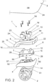
Fig. 2 shows an exploded view of the assembly, -
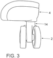
Fig. 3 shows a side view of the caster housing with luggage case feet separately shown, -
Fig. 4 shows parts included in the assembly in extended position, -
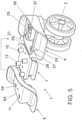
Fig. 5 shows the parts in position prepared for assembling, -
Fig. 6 shows the parts as seen from the under side, and -
Fig. 7 shows in perspective obliquely from below an exploded view of the assembly. - An
assembly 1 for the securing ofcasters 2, skis, runners, and other suitable and possible transportation aids acting against a ground comprises anadapter 6 which is formed of aseparate part 7 and which has one or more coupling means 50. Said coupling means 50 is/are arranged co-operatable with one or more supplementary coupling element/elements 52 situated on acaster holder 51 for acaster housing 4 or another holder for another transportation aid. - A
caster housing 4 arranged on asuitcase 3 comprises arotatable mounting 14 intended for saidluggage case casters 2. Anadapter 6 is formed of anintermediate holder 7 which is situated between a saidcaster housing 4 and asuitcase 3 and which is interlockable with acorner bottom part 8. A saidadapter 6 is arranged to allow to be used for the interlocking ofidentical caster housings 4, etc., intended for different luggage case types, and/or luggage case sizes, or onsuitcases 3 manufactured by vacuum forming. - Said
corner bottom part 8 is shape-adapted to the integratedcorner part 3A of an intended luggage case and which has at least one arc-shaped end portion, preferably two arc-shaped end portions 9, 10. Thecorner bottom part 8 has a plurality of recesses/openings 11 on the respective upper and underside pegs 12 of theholder 7 andcylindrical feet 13 receivable between theluggage case 3 and thecorner bottom part 8 for the bolting of the assembly byfixing screw 18, respectively. - Said recesses/
openings 11 are situated at mutual distances from each other, along the circumference andupper part 15 of thecorner bottom part 8 and of theholder 7, respectively, and thepegs 12 as well as thefeet 13 havescrew holes fixing screws 18 for saidfeet 13 andpegs 12. - Furthermore, the
corner bottom part 8 is arranged to be boltable to saidholder 7 by means ofseparate screws 19, which are received inholes corner bottom part 8 and in theholder 7, respectively. - Said
corner bottom part 8 has at the top aborder 22 which extends along approximately half the circumference portion of the body for the co-operation with thecorner 3A of a saidinterlockable luggage case 3. Thisborder 22 extends in an arched manner along thecorner bottom part 8 on elevatedlevel 24 from the principalflat reception portion 23 of the same as well as from alower level 25 at therespective end portions 9, 10 of the body. - Depending on the size of the
luggage case 3 that is intended to be provided withcasters 2 of standard size and intended kind, anassembly 1 according to the present can be utilized by the fact that theadapter 6 thereof can be interlocked with an intendedcorner bottom part 8 of correct size to fit theluggage case 3 to the same, between theluggage case 3 and theholder 7. Thereby,caster housings 4 of one and the same kind and size can be utilized for several different sizes of luggage cases and for luggage cases of different types. Theholder 7, which is arranged to be placed betweencaster housing 4 and intendedcorner bottom part 8, is arranged to fit to be possible to be interlocked with desired suitable matingcorner bottom part 8. - In desired mating positions, the parts are interlocked by the intended screws being arranged to screw together the above-mentioned parts with each other in order of priority as counted from below.
- As is clearly seen in
Figs. 4-7 , theholder 7 with the paired coupling means 50 thereof is arranged to be possible to be interlocked with thesupplementary coupling elements 52 likewise arranged in pairs, which are arranged on acaster housing 4 or on another holder for another suitable transportation aid, e.g. skis or runners if the luggage case is desired to be provided with such ones for pulling purpose, by being possible to be displaced in relation to each other in thelongitudinal direction 60 of the coupling means. Coupling means 50 andcoupling elements 52 are preferably formed of paired, essentiallyparallel grooves - Furthermore, the
adapter 6 is arranged receivable in and/or connectable with a separate or integratedcorner bottom part 8 for aluggage case 3 in question. In doing so, saidadapter 6 is arranged interlockable and connectable with surroundingcaster holder 51 as well ascorner bottom part 8. - In addition, the part that is provided with female-shaped grooves and the part that is provided with male-shaped grooves, respectively, also has transverse female-shaped and transverse male-shaped, respectively,
end grooves holder 7 are in entirely inserted position, as is shown inFig. 1 . - Furthermore, the
adapter 6 has a plurality ofpegs 12 projecting perpendicularly from theupper part 15 of theholder 7, whichpegs 12 are receivable inmating recesses 11 of thecorner part 8 and which pegs 12 form receivers forfixing screws 18 in assembled parts. - The
adapter 6 is in that connection receivable in acongruent recess 53 of thecorner bottom part 8, which in turn is formed of a separate part or which consists of an integratedcorner part 3A of aluggage case 3 in question. Saidcorner bottom part 8 has throughopenings 11 for the receipt of thepegs 12 of theadapter 6.Cylindrical feet 13 are arranged to surround thepegs 13 from the interior 3B of the luggage case and be fastened by throughscrew 18 in theadapter 6. Saidopenings 11 are situated at mutual distances from each other along the circumference of thecorner bottom part 8 and of theadapter 6, respectively. - The
caster housing 4 is arranged to be fastened to theassembly 1 by ascrew 19 from the interior 3B of the luggage case via throughreception holes corner bottom part 8 and in theadapter 6 as well as in ascrew reception hole 56 in asocket 57 of thecaster housing 4. - Preferably, the
caster housing 4, theholder 7, and the cornerbottom part 8 of theassembly 1 consist of plastic materials of a suitable kind, such as polypropylene, ABS, and/or nylon. - The corner
bottom part 8 has aborder 22, which extends approximately along half the circumference portion of the corner bottom part and thisborder 22 extends in an arched manner on elevated level from the primarilyflat reception portion 23 of the same as well as from alower level 25 at therespective end portions 9, 10 of the body. - The function and nature of the invention should have been clearly understood from the above-mentioned and also with knowledge of what is shown in the drawings but the invention is naturally not limited to the embodiments described above and shown in the accompanying drawings. Modifications are feasible, particularly as for the nature of the different parts, or by using an equivalent technique, without departing from the protection area of the invention, such as it is defined in the claims.
- The arrows in the drawings show how the different parts are assembled by being displaced in relation to each other as well as being lowered down toward each other.
Claims (8)
- Assembly (1) for securing luggage case casters (2), skis, and other transportation aids of a luggage case (3) acting against a ground, wherein said assembly (1) comprises:an adapter (6) being formed of a separate holder (7), wherein said adapter (6) has coupling means (50), wherein said coupling means (50) are co-operatable with supplementary coupling elements (52) situated on a caster holder (51) for a caster housing (4) or another holder for another transportation aid; anda separate or integrated corner bottom part (8) of said luggage case (3), wherein the adapter (6) is arranged receivable in and/or is connectable with said corner bottom part (8), whereinthe adapter (6) has a plurality of pegs (12) projecting perpendicularly from the upper part (15) thereof, which are receivable in openings (11) of the corner bottom part (8) and which pegs (12) form receivers for fixing screws (18), andthe corner bottom part (8) further has cylindrical feet (13) being arranged to surround the pegs (12) from the interior (3B) of the luggage case and be fastened by fixing screws (18) in the adapter (6),characterized in that the caster housing (4) is arranged to be fastened to the assembly (1) by a screw (19) from the interior (3B) of the luggage case (3) via through reception holes (54, 55) in the corner bottom part (8) and the adapter (6) as well as via a screw reception hole (56) in a socket (57) of the caster housing (4).
- Assembly (1) according to claim 1, wherein the coupling means (50) of the adapter (6) and the coupling elements (52) of the caster holder (51) are formed as paired, essentially parallel grooves (28, 29) at mutual distances (A, B) from each other.
- Assembly (1) according to claim 1, wherein the adapter (6) is receivable with the main part thereof in a congruent recess (53) of the corner bottom part (8).
- Assembly (1) according to any one of the above claims, wherein the corner bottom part (8) is formed of a separate part or consists of an integrated corner part (3A) of said luggage case (3).
- Assembly (1) according to claim 1, wherein the openings (11) are situated at mutual distances from each other, along the circumference of the corner bottom part (8) and of the adapter (6), respectively.
- Assembly (1) according to any one of the above claims, wherein the caster housing (4), the holder (7), and the corner bottom part (8) of the assembly (1) consist of plastic material, such as polypropylene, ABS, and/or nylon.
- Assembly (1) according to any one of the above claims, wherein the corner bottom part (8) has a border (22) which extends along approximately half the circumference portion of the corner bottom part (8).
- Assembly (1) according to claim 7, wherein the border (22) extends in an arched manner along the corner bottom part (8) on elevated level from a primarily flat reception portion (23) of the same as well as from a lower level (25) at respective end portions (9, 10) of the corner bottom part (8).
Applications Claiming Priority (2)
| Application Number | Priority Date | Filing Date | Title |
|---|---|---|---|
| SE1750312A SE542180C2 (en) | 2017-03-16 | 2017-03-16 | Device for bag wheels |
| PCT/SE2018/050255 WO2018169478A1 (en) | 2017-03-16 | 2018-03-15 | Caster assembly for a luggage case |
Publications (3)
| Publication Number | Publication Date |
|---|---|
| EP3595484A1 EP3595484A1 (en) | 2020-01-22 |
| EP3595484A4 EP3595484A4 (en) | 2020-12-23 |
| EP3595484B1 true EP3595484B1 (en) | 2022-02-02 |
Family
ID=63522616
Family Applications (1)
| Application Number | Title | Priority Date | Filing Date |
|---|---|---|---|
| EP18767063.3A Active EP3595484B1 (en) | 2017-03-16 | 2018-03-15 | Caster assembly for a luggage case |
Country Status (4)
| Country | Link |
|---|---|
| EP (1) | EP3595484B1 (en) |
| CN (1) | CN110582214B (en) |
| SE (1) | SE542180C2 (en) |
| WO (1) | WO2018169478A1 (en) |
Cited By (1)
| Publication number | Priority date | Publication date | Assignee | Title |
|---|---|---|---|---|
| US12434507B2 (en) * | 2023-10-21 | 2025-10-07 | Jerry Moon | Structure for assembling snap-on caster of draw-bar case |
Families Citing this family (16)
| Publication number | Priority date | Publication date | Assignee | Title |
|---|---|---|---|---|
| US11976498B2 (en) | 2017-06-12 | 2024-05-07 | Yeti Coolers, Llc | Container and latching system |
| US11685573B2 (en) | 2017-06-12 | 2023-06-27 | Yeti Coolers, Llc | Carry strap for container |
| AU201717615S (en) | 2017-06-12 | 2018-01-15 | Yeti Coolers | Container |
| US12108853B2 (en) | 2019-01-06 | 2024-10-08 | Yeti Coolers, Llc | Luggage system |
| WO2018231826A1 (en) | 2017-06-12 | 2018-12-20 | Yeti Coolers, Llc | Container and latching system |
| USD904829S1 (en) | 2018-12-11 | 2020-12-15 | Yeti Coolers, Llc | Container accessories |
| USD907445S1 (en) | 2018-12-11 | 2021-01-12 | Yeti Coolers, Llc | Container accessories |
| US12225993B2 (en) | 2019-01-06 | 2025-02-18 | Yeti Coolers, Llc | Luggage system |
| MX2021008199A (en) | 2019-01-06 | 2021-11-12 | Yeti Coolers Llc | LUGGAGE SYSTEM. |
| USD963344S1 (en) | 2020-06-30 | 2022-09-13 | Yeti Coolers, Llc | Luggage |
| USD954436S1 (en) | 2020-06-30 | 2022-06-14 | Yeti Coolers, Llc | Luggage |
| USD961926S1 (en) | 2020-06-30 | 2022-08-30 | Yeti Coolers, Llc | Luggage |
| USD951643S1 (en) | 2020-06-30 | 2022-05-17 | Yeti Coolers, Llc | Luggage |
| USD985937S1 (en) | 2020-12-16 | 2023-05-16 | Yeti Coolers, Llc | Container |
| USD960648S1 (en) | 2020-12-16 | 2022-08-16 | Yeti Coolers, Llc | Container accessory |
| USD994438S1 (en) | 2020-12-16 | 2023-08-08 | Yeti Coolers, Llc | Container |
Family Cites Families (9)
| Publication number | Priority date | Publication date | Assignee | Title |
|---|---|---|---|---|
| GB1407025A (en) * | 1972-04-11 | 1975-09-24 | Macarthur R C M | Luggage trolleys |
| US4026570A (en) * | 1975-09-29 | 1977-05-31 | Presto Lock Company, Division Of Walter Kidde & Company, Inc. | Caster for luggage |
| US4332052A (en) * | 1978-06-13 | 1982-06-01 | Presto Lock Company, Division Of Walter Kidde & Company, Inc. | Support assembly for luggage |
| US4422212A (en) * | 1981-07-07 | 1983-12-27 | Julius Sheiman | Non-readily detachable luggage support unit |
| US5365635A (en) * | 1993-08-04 | 1994-11-22 | Jang Shis Wen | Retractable caster assembly |
| CN2618790Y (en) * | 2003-02-26 | 2004-06-02 | 乔工科技股份有限公司 | Rotary angle wheel capable of automatic position |
| CN103110257A (en) * | 2013-01-30 | 2013-05-22 | 仇榕谦 | Split universal wheel easy to replace |
| CN204123886U (en) * | 2014-05-16 | 2015-01-28 | 仇炫 | A kind of cardan wheel for convenience detach |
| CN205573491U (en) * | 2016-05-05 | 2016-09-14 | 廖银才 | Novel can dismantle universal wheel |
-
2017
- 2017-03-16 SE SE1750312A patent/SE542180C2/en unknown
-
2018
- 2018-03-15 WO PCT/SE2018/050255 patent/WO2018169478A1/en not_active Ceased
- 2018-03-15 CN CN201880018393.5A patent/CN110582214B/en active Active
- 2018-03-15 EP EP18767063.3A patent/EP3595484B1/en active Active
Cited By (1)
| Publication number | Priority date | Publication date | Assignee | Title |
|---|---|---|---|---|
| US12434507B2 (en) * | 2023-10-21 | 2025-10-07 | Jerry Moon | Structure for assembling snap-on caster of draw-bar case |
Also Published As
| Publication number | Publication date |
|---|---|
| WO2018169478A1 (en) | 2018-09-20 |
| SE1750312A1 (en) | 2018-09-17 |
| EP3595484A4 (en) | 2020-12-23 |
| CN110582214B (en) | 2021-12-31 |
| CN110582214A (en) | 2019-12-17 |
| SE542180C2 (en) | 2020-03-10 |
| EP3595484A1 (en) | 2020-01-22 |
Similar Documents
| Publication | Publication Date | Title |
|---|---|---|
| EP3595484B1 (en) | Caster assembly for a luggage case | |
| US11740082B2 (en) | Level including removable end caps | |
| US11051598B2 (en) | Magnetic closure, particularly for bags, rucksacks and the like | |
| US10384844B2 (en) | Container with padlock mount | |
| US9340136B2 (en) | Two-piece vehicle floor cover retention device | |
| USD534448S1 (en) | Authentication device | |
| US20100025307A1 (en) | Screening Arrangement | |
| US7455546B1 (en) | Electrical power strip plug retention | |
| CN104824950A (en) | Adjustable and removable spacers for luggage | |
| US10168010B1 (en) | Ground insert garden lamp | |
| KR20200020663A (en) | Magnetic hook | |
| US20110168711A1 (en) | Drain cover with locking mechanism | |
| US20070113383A1 (en) | Magnetic closure particularly for bags, rucksacks and the like | |
| US20020178685A1 (en) | Construction element and coupling device therefor | |
| US11457739B2 (en) | Chair leg mountable coaster assembly | |
| US11392171B2 (en) | Holder for mobile electronic device | |
| US7377136B1 (en) | Computer security hook system with corresponding pegs, holes and rings | |
| US11030511B2 (en) | Housing for identification device | |
| US20150272266A1 (en) | Shoe protecting cover device | |
| US10165840B2 (en) | Locking fastener system | |
| KR20080002791U (en) | trowel | |
| DE102023101383B4 (en) | Modular fashion and transport accessories, in particular buckles, ring elements and cord ends | |
| ES1061284U (en) | Cable protector assembly, especially for furniture (Machine-translation by Google Translate, not legally binding) | |
| KR102563420B1 (en) | Snap button apparatus | |
| US954736A (en) | Bag-fastener. |
Legal Events
| Date | Code | Title | Description |
|---|---|---|---|
| STAA | Information on the status of an ep patent application or granted ep patent |
Free format text: STATUS: THE INTERNATIONAL PUBLICATION HAS BEEN MADE |
|
| PUAI | Public reference made under article 153(3) epc to a published international application that has entered the european phase |
Free format text: ORIGINAL CODE: 0009012 |
|
| STAA | Information on the status of an ep patent application or granted ep patent |
Free format text: STATUS: REQUEST FOR EXAMINATION WAS MADE |
|
| 17P | Request for examination filed |
Effective date: 20190823 |
|
| AK | Designated contracting states |
Kind code of ref document: A1 Designated state(s): AL AT BE BG CH CY CZ DE DK EE ES FI FR GB GR HR HU IE IS IT LI LT LU LV MC MK MT NL NO PL PT RO RS SE SI SK SM TR |
|
| AX | Request for extension of the european patent |
Extension state: BA ME |
|
| DAV | Request for validation of the european patent (deleted) | ||
| DAX | Request for extension of the european patent (deleted) | ||
| A4 | Supplementary search report drawn up and despatched |
Effective date: 20201120 |
|
| RIC1 | Information provided on ipc code assigned before grant |
Ipc: A45C 5/14 20060101AFI20201116BHEP Ipc: B60B 33/00 20060101ALI20201116BHEP |
|
| RIC1 | Information provided on ipc code assigned before grant |
Ipc: B60B 33/00 20060101ALI20210731BHEP Ipc: A45C 5/14 20060101AFI20210731BHEP |
|
| GRAP | Despatch of communication of intention to grant a patent |
Free format text: ORIGINAL CODE: EPIDOSNIGR1 |
|
| STAA | Information on the status of an ep patent application or granted ep patent |
Free format text: STATUS: GRANT OF PATENT IS INTENDED |
|
| INTG | Intention to grant announced |
Effective date: 20210921 |
|
| GRAS | Grant fee paid |
Free format text: ORIGINAL CODE: EPIDOSNIGR3 |
|
| GRAA | (expected) grant |
Free format text: ORIGINAL CODE: 0009210 |
|
| STAA | Information on the status of an ep patent application or granted ep patent |
Free format text: STATUS: THE PATENT HAS BEEN GRANTED |
|
| AK | Designated contracting states |
Kind code of ref document: B1 Designated state(s): AL AT BE BG CH CY CZ DE DK EE ES FI FR GB GR HR HU IE IS IT LI LT LU LV MC MK MT NL NO PL PT RO RS SE SI SK SM TR |
|
| REG | Reference to a national code |
Ref country code: GB Ref legal event code: FG4D |
|
| REG | Reference to a national code |
Ref country code: CH Ref legal event code: EP Ref country code: AT Ref legal event code: REF Ref document number: 1466357 Country of ref document: AT Kind code of ref document: T Effective date: 20220215 |
|
| REG | Reference to a national code |
Ref country code: DE Ref legal event code: R096 Ref document number: 602018030389 Country of ref document: DE |
|
| REG | Reference to a national code |
Ref country code: IE Ref legal event code: FG4D |
|
| REG | Reference to a national code |
Ref country code: LT Ref legal event code: MG9D |
|
| REG | Reference to a national code |
Ref country code: NL Ref legal event code: MP Effective date: 20220202 |
|
| REG | Reference to a national code |
Ref country code: AT Ref legal event code: MK05 Ref document number: 1466357 Country of ref document: AT Kind code of ref document: T Effective date: 20220202 |
|
| PG25 | Lapsed in a contracting state [announced via postgrant information from national office to epo] |
Ref country code: SE Free format text: LAPSE BECAUSE OF FAILURE TO SUBMIT A TRANSLATION OF THE DESCRIPTION OR TO PAY THE FEE WITHIN THE PRESCRIBED TIME-LIMIT Effective date: 20220202 Ref country code: RS Free format text: LAPSE BECAUSE OF FAILURE TO SUBMIT A TRANSLATION OF THE DESCRIPTION OR TO PAY THE FEE WITHIN THE PRESCRIBED TIME-LIMIT Effective date: 20220202 Ref country code: PT Free format text: LAPSE BECAUSE OF FAILURE TO SUBMIT A TRANSLATION OF THE DESCRIPTION OR TO PAY THE FEE WITHIN THE PRESCRIBED TIME-LIMIT Effective date: 20220602 Ref country code: NO Free format text: LAPSE BECAUSE OF FAILURE TO SUBMIT A TRANSLATION OF THE DESCRIPTION OR TO PAY THE FEE WITHIN THE PRESCRIBED TIME-LIMIT Effective date: 20220502 Ref country code: NL Free format text: LAPSE BECAUSE OF FAILURE TO SUBMIT A TRANSLATION OF THE DESCRIPTION OR TO PAY THE FEE WITHIN THE PRESCRIBED TIME-LIMIT Effective date: 20220202 Ref country code: LT Free format text: LAPSE BECAUSE OF FAILURE TO SUBMIT A TRANSLATION OF THE DESCRIPTION OR TO PAY THE FEE WITHIN THE PRESCRIBED TIME-LIMIT Effective date: 20220202 Ref country code: HR Free format text: LAPSE BECAUSE OF FAILURE TO SUBMIT A TRANSLATION OF THE DESCRIPTION OR TO PAY THE FEE WITHIN THE PRESCRIBED TIME-LIMIT Effective date: 20220202 Ref country code: ES Free format text: LAPSE BECAUSE OF FAILURE TO SUBMIT A TRANSLATION OF THE DESCRIPTION OR TO PAY THE FEE WITHIN THE PRESCRIBED TIME-LIMIT Effective date: 20220202 Ref country code: BG Free format text: LAPSE BECAUSE OF FAILURE TO SUBMIT A TRANSLATION OF THE DESCRIPTION OR TO PAY THE FEE WITHIN THE PRESCRIBED TIME-LIMIT Effective date: 20220502 |
|
| PG25 | Lapsed in a contracting state [announced via postgrant information from national office to epo] |
Ref country code: PL Free format text: LAPSE BECAUSE OF FAILURE TO SUBMIT A TRANSLATION OF THE DESCRIPTION OR TO PAY THE FEE WITHIN THE PRESCRIBED TIME-LIMIT Effective date: 20220202 Ref country code: LV Free format text: LAPSE BECAUSE OF FAILURE TO SUBMIT A TRANSLATION OF THE DESCRIPTION OR TO PAY THE FEE WITHIN THE PRESCRIBED TIME-LIMIT Effective date: 20220202 Ref country code: GR Free format text: LAPSE BECAUSE OF FAILURE TO SUBMIT A TRANSLATION OF THE DESCRIPTION OR TO PAY THE FEE WITHIN THE PRESCRIBED TIME-LIMIT Effective date: 20220503 Ref country code: FI Free format text: LAPSE BECAUSE OF FAILURE TO SUBMIT A TRANSLATION OF THE DESCRIPTION OR TO PAY THE FEE WITHIN THE PRESCRIBED TIME-LIMIT Effective date: 20220202 Ref country code: AT Free format text: LAPSE BECAUSE OF FAILURE TO SUBMIT A TRANSLATION OF THE DESCRIPTION OR TO PAY THE FEE WITHIN THE PRESCRIBED TIME-LIMIT Effective date: 20220202 |
|
| PG25 | Lapsed in a contracting state [announced via postgrant information from national office to epo] |
Ref country code: IS Free format text: LAPSE BECAUSE OF FAILURE TO SUBMIT A TRANSLATION OF THE DESCRIPTION OR TO PAY THE FEE WITHIN THE PRESCRIBED TIME-LIMIT Effective date: 20220602 |
|
| PG25 | Lapsed in a contracting state [announced via postgrant information from national office to epo] |
Ref country code: SM Free format text: LAPSE BECAUSE OF FAILURE TO SUBMIT A TRANSLATION OF THE DESCRIPTION OR TO PAY THE FEE WITHIN THE PRESCRIBED TIME-LIMIT Effective date: 20220202 Ref country code: SK Free format text: LAPSE BECAUSE OF FAILURE TO SUBMIT A TRANSLATION OF THE DESCRIPTION OR TO PAY THE FEE WITHIN THE PRESCRIBED TIME-LIMIT Effective date: 20220202 Ref country code: RO Free format text: LAPSE BECAUSE OF FAILURE TO SUBMIT A TRANSLATION OF THE DESCRIPTION OR TO PAY THE FEE WITHIN THE PRESCRIBED TIME-LIMIT Effective date: 20220202 Ref country code: EE Free format text: LAPSE BECAUSE OF FAILURE TO SUBMIT A TRANSLATION OF THE DESCRIPTION OR TO PAY THE FEE WITHIN THE PRESCRIBED TIME-LIMIT Effective date: 20220202 Ref country code: DK Free format text: LAPSE BECAUSE OF FAILURE TO SUBMIT A TRANSLATION OF THE DESCRIPTION OR TO PAY THE FEE WITHIN THE PRESCRIBED TIME-LIMIT Effective date: 20220202 Ref country code: CZ Free format text: LAPSE BECAUSE OF FAILURE TO SUBMIT A TRANSLATION OF THE DESCRIPTION OR TO PAY THE FEE WITHIN THE PRESCRIBED TIME-LIMIT Effective date: 20220202 |
|
| REG | Reference to a national code |
Ref country code: CH Ref legal event code: PL |
|
| REG | Reference to a national code |
Ref country code: DE Ref legal event code: R097 Ref document number: 602018030389 Country of ref document: DE |
|
| PG25 | Lapsed in a contracting state [announced via postgrant information from national office to epo] |
Ref country code: MC Free format text: LAPSE BECAUSE OF FAILURE TO SUBMIT A TRANSLATION OF THE DESCRIPTION OR TO PAY THE FEE WITHIN THE PRESCRIBED TIME-LIMIT Effective date: 20220202 Ref country code: AL Free format text: LAPSE BECAUSE OF FAILURE TO SUBMIT A TRANSLATION OF THE DESCRIPTION OR TO PAY THE FEE WITHIN THE PRESCRIBED TIME-LIMIT Effective date: 20220202 |
|
| REG | Reference to a national code |
Ref country code: BE Ref legal event code: MM Effective date: 20220331 |
|
| PLBE | No opposition filed within time limit |
Free format text: ORIGINAL CODE: 0009261 |
|
| STAA | Information on the status of an ep patent application or granted ep patent |
Free format text: STATUS: NO OPPOSITION FILED WITHIN TIME LIMIT |
|
| 26N | No opposition filed |
Effective date: 20221103 |
|
| PG25 | Lapsed in a contracting state [announced via postgrant information from national office to epo] |
Ref country code: LU Free format text: LAPSE BECAUSE OF NON-PAYMENT OF DUE FEES Effective date: 20220315 Ref country code: LI Free format text: LAPSE BECAUSE OF NON-PAYMENT OF DUE FEES Effective date: 20220331 Ref country code: IE Free format text: LAPSE BECAUSE OF NON-PAYMENT OF DUE FEES Effective date: 20220315 Ref country code: FR Free format text: LAPSE BECAUSE OF NON-PAYMENT OF DUE FEES Effective date: 20220402 Ref country code: CH Free format text: LAPSE BECAUSE OF NON-PAYMENT OF DUE FEES Effective date: 20220331 |
|
| PG25 | Lapsed in a contracting state [announced via postgrant information from national office to epo] |
Ref country code: SI Free format text: LAPSE BECAUSE OF FAILURE TO SUBMIT A TRANSLATION OF THE DESCRIPTION OR TO PAY THE FEE WITHIN THE PRESCRIBED TIME-LIMIT Effective date: 20220202 Ref country code: BE Free format text: LAPSE BECAUSE OF NON-PAYMENT OF DUE FEES Effective date: 20220331 |
|
| PG25 | Lapsed in a contracting state [announced via postgrant information from national office to epo] |
Ref country code: MK Free format text: LAPSE BECAUSE OF FAILURE TO SUBMIT A TRANSLATION OF THE DESCRIPTION OR TO PAY THE FEE WITHIN THE PRESCRIBED TIME-LIMIT Effective date: 20220202 Ref country code: CY Free format text: LAPSE BECAUSE OF FAILURE TO SUBMIT A TRANSLATION OF THE DESCRIPTION OR TO PAY THE FEE WITHIN THE PRESCRIBED TIME-LIMIT Effective date: 20220202 |
|
| PG25 | Lapsed in a contracting state [announced via postgrant information from national office to epo] |
Ref country code: HU Free format text: LAPSE BECAUSE OF FAILURE TO SUBMIT A TRANSLATION OF THE DESCRIPTION OR TO PAY THE FEE WITHIN THE PRESCRIBED TIME-LIMIT; INVALID AB INITIO Effective date: 20180315 |
|
| PG25 | Lapsed in a contracting state [announced via postgrant information from national office to epo] |
Ref country code: TR Free format text: LAPSE BECAUSE OF FAILURE TO SUBMIT A TRANSLATION OF THE DESCRIPTION OR TO PAY THE FEE WITHIN THE PRESCRIBED TIME-LIMIT Effective date: 20220202 |
|
| PG25 | Lapsed in a contracting state [announced via postgrant information from national office to epo] |
Ref country code: MT Free format text: LAPSE BECAUSE OF FAILURE TO SUBMIT A TRANSLATION OF THE DESCRIPTION OR TO PAY THE FEE WITHIN THE PRESCRIBED TIME-LIMIT Effective date: 20220202 |
|
| PGFP | Annual fee paid to national office [announced via postgrant information from national office to epo] |
Ref country code: GB Payment date: 20260119 Year of fee payment: 9 |
|
| PGFP | Annual fee paid to national office [announced via postgrant information from national office to epo] |
Ref country code: DE Payment date: 20260217 Year of fee payment: 9 |
|
| PGFP | Annual fee paid to national office [announced via postgrant information from national office to epo] |
Ref country code: IT Payment date: 20260227 Year of fee payment: 9 |