EP3595435B1 - Zusammenklappbare tierbehälteranordnung - Google Patents
Zusammenklappbare tierbehälteranordnung Download PDFInfo
- Publication number
- EP3595435B1 EP3595435B1 EP18766666.4A EP18766666A EP3595435B1 EP 3595435 B1 EP3595435 B1 EP 3595435B1 EP 18766666 A EP18766666 A EP 18766666A EP 3595435 B1 EP3595435 B1 EP 3595435B1
- Authority
- EP
- European Patent Office
- Prior art keywords
- collapsible
- vertical member
- disposed
- horizontal
- crate assembly
- Prior art date
- Legal status (The legal status is an assumption and is not a legal conclusion. Google has not performed a legal analysis and makes no representation as to the accuracy of the status listed.)
- Active
Links
Images







Classifications
-
- A—HUMAN NECESSITIES
- A01—AGRICULTURE; FORESTRY; ANIMAL HUSBANDRY; HUNTING; TRAPPING; FISHING
- A01K—ANIMAL HUSBANDRY; AVICULTURE; APICULTURE; PISCICULTURE; FISHING; REARING OR BREEDING ANIMALS, NOT OTHERWISE PROVIDED FOR; NEW BREEDS OF ANIMALS
- A01K1/00—Housing animals; Equipment therefor
- A01K1/02—Pigsties; Dog-kennels; Rabbit-hutches or the like
- A01K1/0236—Transport boxes, bags, cages, baskets, harnesses for animals; Fittings therefor
- A01K1/0245—Boxes or cages
-
- A—HUMAN NECESSITIES
- A01—AGRICULTURE; FORESTRY; ANIMAL HUSBANDRY; HUNTING; TRAPPING; FISHING
- A01K—ANIMAL HUSBANDRY; AVICULTURE; APICULTURE; PISCICULTURE; FISHING; REARING OR BREEDING ANIMALS, NOT OTHERWISE PROVIDED FOR; NEW BREEDS OF ANIMALS
- A01K1/00—Housing animals; Equipment therefor
- A01K1/02—Pigsties; Dog-kennels; Rabbit-hutches or the like
- A01K1/03—Housing for domestic or laboratory animals
- A01K1/033—Cat or dog houses
-
- A—HUMAN NECESSITIES
- A01—AGRICULTURE; FORESTRY; ANIMAL HUSBANDRY; HUNTING; TRAPPING; FISHING
- A01K—ANIMAL HUSBANDRY; AVICULTURE; APICULTURE; PISCICULTURE; FISHING; REARING OR BREEDING ANIMALS, NOT OTHERWISE PROVIDED FOR; NEW BREEDS OF ANIMALS
- A01K31/00—Housing birds
- A01K31/06—Cages, e.g. for singing birds
- A01K31/08—Collapsible cages
Definitions
- the present disclosure relates to the pet industry generally and more specifically to pet crates.
- a collapsible pet crate assembly comprises: a support frame for supporting a mesh network in a deployed position, having a bottom, a top, a first collapsible vertical member, a second collapsible vertical member, a third collapsible vertical member and a fourth collapsible vertical member; a front side comprising the first vertical member and the second vertical member and a first horizontal top member and a mesh network disposed between the first vertical member and the second vertical member and the first horizontal top member; a rear side comprising the third vertical member and the fourth vertical member and a second horizontal top member, and a mesh network disposed between the third vertical member and the fourth vertical member and the second horizontal top member; a first side comprising the first vertical member and the fourth vertical member and a collapsible mesh network disposed between the first vertical member and the fourth vertical member; a second side comprising the second vertical member and the third vertical member and a collapsible mesh network disposed between the second vertical member and the third vertical member and the third
- directional and spatial terms such as “horizontal,” “vertical,” “horizontally,” “vertically,” and “upward” are not intended to be binding terms.
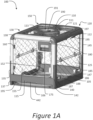
- a collapsible crate assembly 100 comprises a bottom 105, a top 110, a front 115, a rear 120, a first side 125 and a second side 130.
- a support frame is defined by four vertical members extending upward from the bottom 105, including a first collapsible vertical member 135, a second collapsible vertical member 140, a third collapsible vertical member 145 and a fourth collapsible vertical member 150.
- the support frame is employed to support a mesh network 155 forming an enclosure of the collapsible crate assembly 100.
- the mesh network 155 may include diamond shaped openings, ( Figures 1A , 6 , 7C ), rounded openings ( Figures 4A , 5 , 7A , 7B ), rectangular openings ( Figures 1B-3 ), or any other appropriate shape.
- the collapsible crate assembly 100 may include as many as six doors/openings.
- the bottom 105 includes a panel 106 for contact with a floor, a ground or any suitable surface such that the panel 106 is below the tray 450.
- the panel 106 is a solid panel.
- the bottom 105 can further include feet for contacting the ground or any suitable surface.
- the bottom 105 can include polymer feet (e.g., natural rubber feet, polystyrene feet, synthetic rubber feet, any suitable polymer material, or any combination thereof), silicon-based feet (e.g., silicone, polysilicon, or any suitable silicon-based material), or any suitable material feet.
- Feet can be in incorporated onto the bottom 105 to prevent scratching when placed on the ground or any suitable surface, reduce noise created by an active animal, and reduce shock and/or stresses applied to the crate by the active animal.
- the bottom 105 forms a basis for a support structure of the collapsible crate assembly 100, having a first collapsible vertical member 135 extending from a first corner 137, a second collapsible vertical member 140 extending from a second corner 142, a front top horizontal member 138 joining the first collapsible vertical member 135 and the second collapsible vertical member 140, a third collapsible vertical member 145 extending from a third corner 147, a fourth collapsible vertical member 150 extending from a fourth corner 152 and a rear top horizontal member 121 joining the third collapsible vertical member 145 and the fourth collapsible vertical member 150.
- each of the collapsible vertical members (135, 140, 145, 150) is integral with the panel 106 while in other embodiments, each of the collapsible vertical members (135, 140, 145, 150) is a separate component that is attached to the solid panel 106.
- a tray slot 195 can be disposed within the front 115 between the first corner 137 and the second corner 142, the rear 120 between the third corner 147 and the fourth corner 152, the first side 125 between the second corner 142 and the third corner 147, or the second side 130 between the fourth corner 152 and the first corner 137.
- a tray 450 (see Figures 4 and 7A ) can be disposed above the panel 106 for cleaning and/or animal byproduct removal. The tray 450 can be extracted through the tray slot 195. The tray 450 can be reinserted through the tray slot 195.
- the tray 450 can have any suitable design such that when inserted into the collapsible crate assembly 100 the tray 450 can cover an interior of the bottom 105 and prevent spillage of water, food, and/or animal byproduct.
- the tray 450 can have a same shape as the bottom 105 (e.g., a rectangular bottom 105 can employ a rectangular tray 450, an elliptical bottom 105 can employ an elliptical tray 450, and the like).
- the tray 450 can have a lip 710 extending upward (see Figure 7A ).
- the lip 710 can extend vertically upward from a bottom of the tray 450. In some cases, the lip 710 can extend upward at an angle other than vertical from the tray 450.
- the lip 710 can extend upward from the tray 450 at an angle from about 90° to approximately 30°.
- the lip 710 can extend upward from the tray 450 at an angle of 90°, 75°, 60°, 45°, 30°, or other appropriate angle.
- the bottom 105 can include a locking mechanism to secure the tray 450 into place when in service beneath an animal contained within the collapsible crate assembly 100.
- the locking mechanism can be an indentation or notch (not shown) disposed within a portion of the bottom 105 and a corresponding protrusion (not shown) disposed in the tray 450 such that when the tray 450 is fully inserted, the protrusion can engage the indentation thus locking the tray 450 in the collapsible crate assembly 100.
- the protrusion may be a static component, a ball spring, a spring pin, a barb, or any other appropriate structure.
- Applying a force to the tray 450 can disengage the protrusion from the indentation enabling removal of the tray 450 from the collapsible crate assembly 100.
- the force required to enable removal of the tray 450 from the collapsible crate assembly 100 can be greater than a force an animal contained within the collapsible crate assembly 100 can apply to the tray 450 from within the collapsible crate assembly 100, providing a safe enclosure for the animal (e.g., the animal may not enable the tray 450 to slide out of the collapsible crate assembly 100).
- the front 115 comprises the first collapsible vertical member 135 and the second collapsible member 140 and a front top horizontal member 138.
- the first collapsible vertical member 135 and the second collapsible member 140 and the front top horizontal member 138 can be a single extruded part 900 (see Figure 9 ).
- the rear 120 comprises the third collapsible vertical member 145 and the fourth vertical member 150 and a rear top horizontal member 121.
- the third collapsible vertical member 145 and the fourth vertical member 150 and the rear top horizontal member 121 can be a single extruded part 900 (see Figure 9 ).
- the mesh network 155 disposed between the first collapsible vertical member 135 and the second collapsible vertical member 140 and the front top horizontal member 138 is a front door.
- the mesh network 155 disposed between the third collapsible vertical member 145 and the fourth collapsible vertical member 150 and the rear top horizontal member 121 can be a rear door.
- the front door can attach to the first collapsible vertical member 135 or the second collapsible vertical member 140 with hinges 160 forming a horizontally opening front door.
- the optional rear door can attach to the third collapsible vertical member 145 or the fourth collapsible vertical member 150 with hinges 160 forming a horizontally opening rear door.
- the front door can attach to the front top horizontal member 138 with hinges 160 forming an upward opening front door.
- the optional rear door can attach to the rear top horizontal member 121 with hinges 160 forming an upward opening optional rear door.
- the front and rear doors can have latch pins (not shown) disposed on a side opposite the hinges 160 (e.g., hinges 160 can be attached to the first collapsible vertical member 135 and the latch pins can be disposed adjacent to the second collapsible vertical member 140), such that the latch pins can engage latch pin receivers (not visible) disposed on the first collapsible vertical member 135, the second collapsible vertical member 140, the third collapsible vertical member 145 or the fourth collapsible vertical member 150; a latch pin release mechanism 175, wherein the latch pin release mechanism 175 is disposed within a housing 180 making it accessible to a human user outside of the crate assembly 100 and inaccessible to an animal contained within the crate assembly 100 when the crate assembly 100 is in a deployed position.
- latch pins (not shown) disposed on a side opposite the hinges 160 (e.g., hinges 160 can be attached to the first collapsible vertical member 135 and the latch pins
- the latch pin release mechanism 175 is spring loaded such that the latch pins are normally engaged in the latch pin receivers.
- the latch pin release mechanism 175 must be depressed to disengage the latch pins from the latch pin receivers allowing the front door and rear door to be opened and allowing an animal to enter and/or exit the crate assembly 100.
- the mesh network 155 disposed between the second collapsible vertical member 140 and the third collapsible vertical member 145 is a first side door.
- the mesh network 155 disposed between the fourth collapsible vertical member 150 and the first collapsible vertical member 135 is a second side door.
- the first side door and the second side door attach to a first horizontal side member 112 of the top 110 and the second side door can attach to a second horizontal side member 113 of the top 110 providing a hinged opening first side door and/or a hinged opening second side door.
- the first side door and/or the second side door may include hinges 185.
- the first side door may include one or more hinges 185 disposed along a horizontal member located approximately halfway between bottom 105 and horizontal side member 112.
- the hinge(s) 185 may function such that the first and second doors bifold when the crate assembly 100 moves from the deployed position (see Figure 1A ) into the collapsed position (see Figure 4 ).
- the hinges 185 function as a one-way hinge such that the hinges 185 and center portion of the door move toward the interior of the crate assembly 100 as shown in Figure 11D (i.e., the hinges 185 prevent the respective door from pivoting outward).
- hinges 185 are configured such that an upper and/or lower portion of the first side door (and/or second side door) can pivot to create an opening for access to the interior of the collapsible crate assembly 100 (see Figure 11D ).
- the lower half of the first door may pivot about hinges 185 to an open position to allow a pet to move into or out of the collapsible crate assembly 100 or the upper half of the first door may pivot about hinges 185 to an open position to allow access to the interior (while limiting the chance of the pet exiting the collapsible crate assembly 100).
- the first and/or second doors are configured such that the upper and lower halves are both movable.
- latch pins 186 are disposed on a at least a portion of a bottom side of the first side door and on at least a portion of a bottom side of the second side door each extending longitudinally such that the first side door and/or the second side door can be secured when the crate assembly 100 is in the deployed position and and/or in the collapsed position.
- Latch pins 186 are disposed on at least a portion of a bottom side of the first side door (and/or the second side door).
- the latch pins 186 may be disposed on at least a portion of a bottom side of the first side door (and/or the second side door) such that the each pin engages the respective vertical member (135, 140, 145, 150) in one or more locations.
- the latch pins 186 may engage the vertical members to secure side door in a closed position (see Figure 1A ), an open or partially open position (see Figure 11D ), or an intermediate position.
- the panels of the side door in the open position, are approximately parallel with the ceiling and/or floor of the crate assembly 100.
- at least one of the side doors includes a magnet for holding the door in the open position (i.e., folded or bifolded position as shown in Figure 11D ).
- Guide housings 187 may be disposed on at least a portion of a bottom side of the first side door and the second side door in close proximity to the first collapsible vertical member 135, the second collapsible vertical member 140, the third collapsible vertical member 145 and the fourth collapsible vertical member 150, such that the latch pins 186 can be guided into latch pin receiving slots (not visible) disposed in the respective vertical member.
- the latch pins 186 may be disposed within the guide housings 187 and extend longitudinally through the guide housings 187.
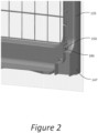
- the latch pin operation actuators 188 may protrude from the guide housings 187, and connect to terminal ends of the latch pins 186 such that the latch pins 186 can be extended into or retracted from the latch pin receiving slots 250 (see Figure 2 ) disposed in the respective vertical member. Movement of the latch pins 186 (via the latch pin operation actuators 188) may release the first side door and/or the second side door to provide an opening for an animal contained within the collapsible crate assembly 100.
- the latch pin operation actuators 188 may include a spring mechanism such that the latch pins 186 are normally engaged within the latch pin receiving slots disposed in the respective vertical member. Movement of the latch pin operation actuators 188 to compress the spring mechanism may disengage the latch pins 186 from the latch pin receiving slots disposed in the respective vertical member.
- the latch pins 186B can be implemented such that engaging and disengaging the latch pins 186B into and out of the latch pin receivers 250 can be a single handed operation.
- the latch pins 186B can be sufficiently long to extend from the latch pin receivers 250, through guide housings 187B disposed adjacent to the respective vertical member to a midpoint of the first side door and/or the second side door and held in place by a latch pin operation housing 189.
- the latch pins 186B can be of a shape such that an end terminating in the latch pin operation housing 189 can extend outward from the latch pin operation housing 189 providing operation handles 188B.
- the operation handles can be simultaneously depressed with one hand, disengaging the latch pins 186B from the latch pin receivers 250, thus allowing opening of the first side door and/or the second side door.
- slide tracks can be disposed within the first collapsible vertical member 135, the second collapsible vertical member 140, the third collapsible vertical member 145 and the fourth collapsible vertical member 150 such that the latch pins 186 may be guided along the respective vertical member during opening of the first side door and/or the second side door.
- the slide tracks can prevent the first side door and/or the second side door from swinging freely during opening and/or closing, providing a safe openable and closeable door for the animal contained within the collapsible crate assembly 100.
- latch pin receivers similar to those described above can be disposed proximal to a top of the vertical members, such that the first side door and/or the second side door can be maintained in an open position by allowing the latch pins 186 to engage the latch pin receivers disposed at the top of the respective vertical member.
- the first side door and/or the second side door may include a magnet for holding the door in the open position (i.e., folded or bifolded position as shown in Figure 11D ).
- a locking mechanism can be disposed within the top 110 such that when the first side door and the second side door are moved into the open position, the hinge(s) 185 and/or a folded portion of the first side door and/or the second side door can be secured to the top 110 preventing the first side door and the second side door from swinging freely while in the open position (e.g. , the first side door and the second side door are maintained substantially horizontal while in the open position).
- the mesh network 155 can be a collapsible mesh comprising a metal mesh, a steel cable mesh, a polymer mesh, or any suitable animal containment mesh, such that a door comprising a collapsible mesh can collapse vertically as the top 110 is lowered effectively compressing the first side 125 and the second side 130 vertically.
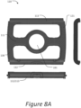
- the top 110 (see Figures 1A , 7B , 7C , and 8 ) includes a first horizontal member 111 disposed between the first side 125 and the second side 130 (in some embodiments, approximately halfway between first side 125 and second side 130) and extending longitudinally between the front side 115 and the rear side 120.
- the top includes a first side horizontal member 112 disposed on top of the first side 125 and a second side horizontal member 113 disposed on top of the second side 130.
- a mesh network 155 is disposed between the first horizontal member 111 and the first side horizontal member 112 and a mesh network 155 disposed between the first horizontal member 111 and the second side horizontal member 113 (see Figure 7B ).
- the mesh networks 155 may include one or more attachments points within the first horizontal member 111 (not visible), the first side horizontal member 112, the second side horizontal member 113, a front top horizontal member 138, and/or a rear top horizontal member 121 (see Figure 7B ).
- the panel formed from the one or more of the mesh networks 155 may be disposed within the top 110 via hinges (not shown) attached to one or more of the first horizontal member 111, the first side horizontal member 112, the second side horizontal member 113, a front top horizontal member 138, and/or a rear top horizontal member 121.
- the mesh network 155 can be opened by pulling upward on a handle disposed opposite the hinges (not shown) creating an opening (similar to the arrangement shown in Figures 11B and 11C ).
- the mesh network 155 can be suspended by tracks located within one or more of the first horizontal member 111, the first side horizontal member 112, the second side horizontal member 113, the front top horizontal member 138, and/or the rear top horizontal member 121.
- the mesh network 155 can be opened by applying force to a handle 720 to move/slide the mesh network 155 (see also: Figure 11A ).
- the mesh network 155 may be at least partially rigid or, in some embodiments, may a flexible component that compresses as the mesh network 155 moves to form an opening.
- a multifunctional handle 190 is disposed within the first horizontal member 111 in an opening 191 (see Figure 1A ) between the front 115 and the rear 120.
- the multifunctional handle 190 enables a user to carry the collapsible crate assembly 100 when in the deployed position and to collapse the collapsible crate assembly 100 when in the deployed position by moving and/or rotating the multifunctional handle 190.
- the multifunctional handle 190 can rotate in either direction (clockwise or counter-clockwise) to allow the collapsible crate assembly 100 to move to the collapsed position.
- the multifunctional handle 190 can only rotate in one direction (clockwise or counter-clockwise) to allow the collapsible crate assembly 100 to move to the collapsed position.
- the multifunctional handle 190 may include one or more springs and/or detents to bias the handle toward one or more positions.
- the multifunctional handle 190 includes a locking feature to secure the multifunctional handle 190 in the deployed position (see Figure 1A ) to prevent unintended or inadvertent collapsing of the collapsible crate assembly 100.
- multifunctional handle 190 is completely enclosed within the first horizontal member 111 to prevent foreign objects from interfering with or damaging the mechanism.
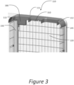
- Top latch pins 310 (see Figure 3 ) disposed within the first horizontal member 111 connect to the multifunctional handle 190 and are disposed longitudinally within the first horizontal member 111 and can insert into latch pin receivers (not visible) disposed within the front top horizontal member 138 or the rear top horizontal member 121. Rotating the multifunctional handle 190 can disengage the top latch pins 310 from the latch pin receivers disposed within the front top horizontal member 138 and the rear top horizontal member 121 enabling the collapsible crate assembly 100 to be collapsed.
- FIG. 4A An embodiment of the invention is presented in Figure 4A .
- the collapsible crate assembly 100 can be collapsed from the deployed position to a collapsed position as illustrated in Figure 4B .
- the multifunctional handle 190 can be rotated disengaging the top latch pins 310 disposed within the first horizontal member 111 from latch pin receivers disposed within the top of the front 115 and the top of the rear 120.
- the hinges 185 of the first side door 410 and the second side door 420 can allow the first side door 410 and the second side door 420 to fold inward (i.e., in a direction such that when folded the first side door is disposed horizontally above at least part of the bottom 105 and the second side door 420 is disposed horizontally above at least part of the bottom 105, see Figure 4B ).
- the first side door 410 and the second side door 420 fold inward simultaneously with the top 110 collapsing downward (block 475).
- the multifunctional handle 190 also controls spring loaded pins that extend from the vertical members (135, 140, 145, 150) at approximately halfway between the bottom 105 and the top 110 to engage the first side door 410 and the second side door 420.
- the front 115 and the rear 120 can be folded inward (see Figure 4B , block 485). Collapsing the front 115 and rear 120 is achieved by pivot points 430 disposed within the first collapsible vertical member 135, the second collapsible vertical member 140, the third collapsible vertical member 145 and the fourth collapsible vertical member 150.
- the collapsible crate assembly 100 is fully collapsed (block 495) when the front 115 and rear 120 are disposed directly above the collapsed first side door 410, second side door 420, and top 110.
- the collapsed crate assembly 100 can be maintained in the collapsed position by a locking mechanism (not shown) disposed within one or more of the first collapsible vertical member 135, the second collapsible vertical member 140, the third collapsible vertical member 145, and/or the fourth collapsible vertical member 150.
- the locking mechanism may be a spring pin (not shown) disposed within or adjacent to the pivot point 430.
- the spring pins engage spring pin receivers disposed at an exterior of the pivot points 430 such that when the front 115 and rear 120 are fully collapsed, a portion of the spring pin is protruding through the spring pin receiver and accessible by a user.
- Protrusion of the spring pin through the spring pin receiver locks the front 115 and/or rear 120 in the collapsed position. Applying a force in the axial direction of the spring pin (not shown) to drive the spring pin into the pivot point can disengage the spring pin from the spring pin receiver, thus unlocking the front 115 and/or rear 120 enabling deployment.
- the locking mechanism can be an indentation or notch (not shown) disposed within a static portion of the pivot point 430 and a corresponding protrusion (not shown) disposed in a movable portion of the pivot point 430 such that when the front 115 and rear 120 are fully collapsed, the protrusion can engage the indentation thus locking the crate assembly 100 in the collapsed position.
- the protrusion may be a static component, a ball spring, a spring pin, a barb, or any other appropriate structure. Applying a force to the front 115 and/or the rear 120 can disengage the protrusion from the indentation enabling deployment.
- the front 115 may include a grip handle 440 at a bottom portion thereof.
- the bottom 105 may include a grip handle 442 located adjacent to the tray slot 195 (see Figure 1A ).
- wheels 510 can be disposed on a bottom portion of the rear 120 of the crate assembly 100.
- the wheels 510 are disposed on a side opposite the grip handle 440 (and/or grip handle 442 (see Figure 1A )).
- the crate assembly 100 can be transported using the wheels in either the collapsed or in the deployed position.
- an additional handle (not shown) may be attached to horizontal front member 138 to pull the crate assembly 100 via the wheels in the deployed position.
- first horizontal side member 112 and/or the second horizontal side member 113 can include a carry handle 195 (see Figure 1A ).
- the carry handle 195 can be a hinged molded handle 610 disposed within the first horizontal side member 112 and/or the second horizontal side member 113.
- the hinged molded handle 610 can have a hinge pin 620 disposed within the hinged molded handle 610 creating a pivoting edge of the hinged molded handle 610 (see Figure 6 ).
- the hinge pin 620 can extend through the hinged molded handle 610 and beyond a first side of the hinged molded handle 610 and beyond a second side of the hinged molded handle 610 such that the hinge pin 620 can be inserted into hinge pin receivers 630 disposed within the first horizontal side member 112 and/or the second horizontal side member 113.
- the hinged molded handle 610 can further include a spring loaded mechanism that can maintain the hinged molded handle 610 in a position such that the hinged molded handle 610 rests within a recess 197 within the first horizontal side member 112 and/or the second horizontal side member 113.
- the recess 197 can have a shape similar to the hinged molded handle 610 having a larger area such that the hinged molded handle 610 can rest flush with an exterior surface the first horizontal side member 112 and/or the second horizontal side member 113.
- the hinged molded handle 610 can be deployed into a position suitable for carrying the collapsed crate assembly 100 by applying sufficient force to overcome the spring loaded mechanism and extending the hinged molded handle 610 outward from the first horizontal side member 112 and/or the second horizontal side member 113 thereby pivoting about the hinge pin 620 disposed within the hinged molded handle 610.
- the carry handle 195 can be a strap attached to the first horizontal side member 112 and/or the second horizontal side member 113.
- the strap can be attached via at least a mechanism that allows the strap to move from a first position wherein the strap is maintained adjacent to the first horizontal side member 112 and/or the second horizontal side member 113 and a second position wherein the strap is extended away from the first horizontal side member 112 and/or the second horizontal side member 113 such that a user can grasp the strap.
- a second mechanism that allows the strap to move from a first position wherein the strap is maintained adjacent to the first horizontal side member 112 and/or the second horizontal side member 113 and a second position wherein the strap is extended away from the first horizontal side member 112 and/or the second horizontal side member 113 such that a user can grasp the strap can be employed, further facilitating motion of the strap from the first position to the second position.
- the carry handle 195 can be a handle molded into the first horizontal side member 112 and/or the second horizontal side member 113 during production of the first horizontal side member 112 and/or the second horizontal side member 113.
- the carry handle 195 can be an elliptical hole disposed within the first horizontal side member 112 and/or the second horizontal side member 113 such that a user can insert at least a portion of the user's hand into the elliptical hole to lift and/or carry the collapsible crate assembly 100.
- first horizontal side member 112 and/or the second horizontal side member 113 of the collapsible crate assembly 100 can have no handles, as in the example of Figure 1B .
- the collapsible crate assembly 100 can be restored to the deployed position.
- the front 115 and rear 120 can be raised from collapsed positions exposing the collapsed top 110.
- the deployed crate assembly 100 can be maintained in the deployed position by a locking mechanism (not shown) disposed within one or more of the first collapsible vertical member 135, the second collapsible vertical member 140, the third collapsible vertical member 145, and/or the fourth collapsible vertical member 150.
- the locking mechanism may be a spring pin (not shown) disposed within or adjacent to the pivot point 430.
- the spring pins engage spring pin receivers disposed at an exterior of the pivot points 430 such that when the front 115 and rear 120 are fully deployed, a portion of the spring pin is protruding through the spring pin receiver and accessible by a user. Protrusion of the spring pin through the spring pin receiver locks the front 115 and/or rear 120 in the deployed position. Applying a force in the axial direction of the spring pin (not shown) to drive the spring pin into the pivot point can disengage the spring pin from the spring pin receiver, thus unlocking the front 115 and/or rear 120 enabling collapse.
- the locking mechanism can be an indentation or notch (not shown) disposed within a static portion of the pivot point 430 with a corresponding protrusion (not shown) disposed in a movable portion of the pivot point 430 such that when the front 115 and rear 120 are fully deployed, the protrusion can engage the indentation thus locking the crate assembly 100 in the deployed position.
- the protrusion may be a static component, a ball spring, a spring pin, a barb, or any other appropriate structure. Applying a force to the front 115 and/or the rear 120 can disengage the protrusion from the indentation enabling collapse.
- the multifunctional handle 190 can be used to raise the top 110 and simultaneously unfold the first side 410 and the second side 420. When the top 110 is fully raised and the first side 410 and the second side 420 are fully extended, the multifunctional handle 190 can be rotated to engage the top latch pins 310 into latch pin receivers (not visible) disposed within the top horizontal front member 138 and disposed within the top horizontal rear member 121.
- the top 1100 may include a first horizontal member 1110 joining the first collapsible vertical member 1135 and the third collapsible vertical member 1145, and a second horizontal member 1115 joining the second collapsible vertical member 1140 and the fourth collapsible vertical member 1150 such that the first horizontal member and the second horizontal member form a cross pattern within the top 1100 of the crate assembly 100.
- the top 1100 can optionally include a first side horizontal member 1112 that can be disposed above the first side 1125 and a second side horizontal member 1113 that can be disposed above the second side 1130.
- the top 1100 can optionally include a mesh network 1155 disposed within areas defined by the first horizontal member and the second horizontal member and the first side horizontal member 1112 and the second side horizontal member 1113 and the top horizontal front member 1138 and the top horizontal rear member 1121.
- the mesh network disposed within the top 1110 may include one or more sections that are triangular, trapezoidal, and/or any other appropriate shape.
- the mesh network 1155 can be openable for top access to an interior of the crate assembly.
- the mesh network can attach to the first horizontal member or the second horizontal member or the first side horizontal member 1112 or the second side horizontal member 1113 or the top horizontal front member 1138 or the top horizontal rear member 1121 with hinges (see Figures 11B and 11C ).
- the mesh network can be secured to the first horizontal member or the second horizontal member or the first side horizontal member 1112 or the second side horizontal member 1113 or the top horizontal front member 1138 or the top horizontal rear member 1121 with clips.
- the clips can be released from the first horizontal member or the second horizontal member or the first side horizontal member 1112 or the second side horizontal member 1113 or the top horizontal front member 1138 or the top horizontal rear member 1121 such that the mesh network 1155 can be opened upward.
- the mesh network 1155 can further be disposed within the top 1110 via attachment points within the first horizontal member 1110 (not visible), the second horizontal member 1115, the first side horizontal member 1112, the second side horizontal member 1113, a front top horizontal member 1138 or a rear top horizontal member 1121 (see Figure 11B ).
- the mesh network 1155 can be suspended by tracks located within the first horizontal member 1111, the second horizontal member 1115, the first side horizontal member 1112, the second side horizontal member 1113, the front top horizontal member 1138 or the rear top horizontal member 1121.
- the mesh network can be opened by applying force to a handle 1160 to slide the mesh network 1155 within the tracks located within the first horizontal member 1110, the second horizontal member 1115, the first side horizontal member 1112, the second side horizontal member 1113, the front top horizontal member 1138 or the rear top horizontal member 1121 thereby compressing the mesh network 1155 and forming an opening.
- the mesh network 1155 can further be disposed within the top 1110 via hinges (not shown) attached to the first horizontal member 1111, the second horizontal member 1115, the first side horizontal member 1112, the second side horizontal member 1113, a front top horizontal member 1138 or a rear top horizontal member 1121.
- the mesh network 1155 can be pivoted upward as a hatch opening by pulling upward on a handle 1160 disposed opposite the hinges.
- the hatch opening may include at least one latch 712 (see Figure 7C ), which can be disengaged to allow the hatch to open.
- a multifunctional handle 1190 is disposed within an intersection of the first horizontal member 1110 and the second horizontal member 1115 at a central point midway between the front 1105 and the rear 1120 and midway between the first side 1125 and the second side 1130.
- the multifunctional handle 1190 enables a human user to carry the collapsible crate assembly 100 when in the deployed position and to collapse the collapsible crate assembly 100 when in the deployed position by rotating the multifunctional handle 1190.
- Top latch pins 310 (see Figure 3 ) disposed within the first horizontal member and the second horizontal member connect to the multifunctional handle 1190 and are disposed longitudinally within the first horizontal member and the second horizontal member and can insert into latch pin receivers (not visible) disposed within the first collapsible vertical member 1135, the second collapsible vertical member 1140, the third collapsible vertical member 1145 and the fourth collapsible vertical member 1150.
- Rotating the multifunctional handle 1190 can disengage the top latch pins 310 from the latch pin receivers disposed within the front top horizontal member 1138 or the rear top horizontal member 1121 enabling the collapsible crate assembly to be collapsed.
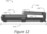
- a collapsible crate assembly 1200 can have dimensions such that a bottom long transverse dimension 1210 is less than a height of the crate assembly multiplied by two, such that when in the collapsed position, a front portion 1220 or a rear portion 1230 can be disposed directly above a collapsed top and sides 1240, and a portion of the rear portion 1230 or a portion of the front portion 1220 can partially rest on the front portion 1220 or the rear portion 1230 disposed directly above the collapsed top and sides 1240 (see Figure 12 ), such that the front portion 1220 and the rear portion 1230 are collapsed asymmetrically.
- pivot points 1250 being disposed at differing heights in a first collapsible vertical member 1260, a second collapsible vertical member (not visible), a third collapsible vertical member 1265 and a fourth collapsible vertical member (not visible), wherein the pivot points 1250 are disposed at equal heights in the first collapsible vertical member 1260, and the second collapsible vertical member (not visible); and wherein the pivot points 1250 are disposed at equal heights in the third collapsible vertical member 1265 and the fourth collapsible vertical member (not visible) (see Figure 12 ).
- a collapsible crate assembly 1300 can have any suitable shape.
- Any suitable shape as used herein, comprises any volumetric shape capable of containing an animal in the spirit of the present disclosure such that the collapsible crate assembly 1300 is easy to operate, aesthetically pleasing, quiet, light, durable, easy to clean, and safe and comfortable for the animal. It will be obvious to a person of skill in the art that differing designs will require differing functional mechanisms in order to achieve the desired characteristics listed above.
- the shape can be an elliptic cylinder (see Figure 13A ).
- the elliptic cylinder crate 1300 comprises a collapsible door assembly 1310, collapsible vertical members 1350, an elliptical bottom assembly 1360, and an elliptical top assembly 1370.
- Figure 13B illustrates a collapsible door assembly 1310 suitable for use in the elliptic cylinder crate design 1300.
- the collapsible door assembly 1310 can pivot about pivot points 1315 allowing the collapsible door assembly 1310 to collapse into the elliptic cylinder crate 1300.
- To deploy the elliptic cylinder crate 1300 when the collapsible door assembly 1310 is in a vertical position the collapsible door assembly 1310 can engage the elliptical top assembly 1370 via a locking handle and clip assembly 1320.
- a removable tray 1330 (see Figure 13C ) can be extracted from a tray slot 1335 for cleaning and removal of any animal byproducts.
- FIG. 13D An exemplary method for deploying and collapsing the elliptic cylinder crate 1300 is illustrated in Figure 13D .
- a collapsed elliptic cylinder crate 1300 (block 1390) can be placed on any suitable surface (e.g., a floor or a ground).
- the collapsible vertical members 1350 can be extended to release a locking mechanism (not shown) (block 1391). Once extended and unlocked, the collapsible vertical members 1350 can be raised upward deploying the elliptical top assembly 1370 and mesh network 1355 (block 1392).
- collapsible vertical members 1350 When the collapsible vertical members 1350 are fully deployed the collapsible vertical members 1350 can be compressed to lock the elliptic cylinder crate 1300 in a deployed position (block 1393).
- the collapsible door assembly(-ies) 1310 can be raised, extended and locked into a deployed position via the locking handle and clip assembly(-ies) 1320 (block 1394).
- the collapsible crate assembly 100 can be produced using any suitable material.
- the collapsible crate assembly includes cast aluminum alloys, extruded aluminum alloys, rolled aluminum alloys, cast steel alloys, rolled steel alloys, extruded steel alloys, stainless steel, blow molded plastics, injection molded plastics, rotational molded plastics, extruded plastics, or any combination thereof.
- the bottom 105 can be an injection molded plastic
- the front 115 and rear 120 can be an aluminum alloy
- the top 110 can be an extruded plastic.
- the components of the collapsible crate assembly 100 may be constructed and/or attached to one another via suitable fasteners, which include, but are not limited to, screws, bolts, rivets, welding, spot welding, adhesive, or other mechanical or chemical fasteners.
- the collapsible crate assembly 100 can include an accessory port disposed within the collapsible crate assembly 100.
- the accessory port can be used to mount a Wi-Fi camera, an automatic feeder, an automatic waterer, a speaker, a mobile cellular device, any combination thereof, or any suitable device a pet owner may want to mount within a pet crate.
- the collapsible crate assembly 100 can include a divider system (e.g., to sequester a plurality of young animals or to provide a smaller environment for at least a young animal).
- the divider system can include a partition.
- the divider system can include grooves disposed within the bottom 105, and corresponding grooves disposed within the top 110, the first horizontal side member 112, the second horizontal side member 113, the front top horizontal member 138, the rear top horizontal member 121, or any suitable portion of the support structure, such that the corresponding grooves disposed within the top 110, the first horizontal side member 112, the second horizontal side member 113, the front top horizontal member 138, the rear top horizontal member 121, or any suitable portion of the support structure are positioned substantially vertically above the grooves disposed within the bottom 105.
- the partition can be inserted into the grooves to create at least a reduced area animal containment area.
- the partition can be any suitable material such that an animal can be contained by the partition, including, for example, metals, alloys, polymers, fabrics, glasses, wood, or ceramics.
- the collapsible crate assembly 100 can include a mat disposed within the tray 450.
- the mat can be a polymer mat (e.g., a natural rubber mat, a polystyrene mat, a synthetic rubber mat, any suitable polymer material, or any combination thereof), a silicon-based mat (e.g. , silicone, polysilicon, or any suitable silicon-based material), or any suitable material mat.
- the collapsible crate assembly 100 can include a mattress disposed within the tray 450.
- the mattress can be a polymer mattress (e.g., a natural rubber mattress, a latex mattress, a synthetic rubber mattress, a memory foam mattress, any suitable polymer material, or any combination thereof), a silicon-based mattress (e.g., silicone, polysilicon, or any suitable silicon-based material), or any suitable material mattress.
- the mattress can further include a mattress cover.
- the mattress cover can be water-proof, rip-proof, removable from the mattress, and washable.
Landscapes
- Life Sciences & Earth Sciences (AREA)
- Environmental Sciences (AREA)
- Zoology (AREA)
- Animal Husbandry (AREA)
- Biodiversity & Conservation Biology (AREA)
- Health & Medical Sciences (AREA)
- Animal Behavior & Ethology (AREA)
- Clinical Laboratory Science (AREA)
- General Health & Medical Sciences (AREA)
- Birds (AREA)
- Housing For Livestock And Birds (AREA)
Claims (12)
- Zusammenlegbare Haustierkistenanordnung (100), umfassend:einen Stützrahmen zur Stützung eines Maschennetzes (155) in einer entfalteten Position, mit einem Boden (105), einem Oberteil (110), einem ersten zusammenlegbaren vertikalen Element (135), einem zweiten zusammenlegbaren vertikalen Element (140), einem dritten zusammenlegbaren vertikalen Element (145) und einem vierten zusammenlegbaren vertikalen Element (150);eine Vorderseite (115), die das erste vertikale Element (135) und das zweite vertikale Element (140) und ein erstes horizontales oberes Element (138) sowie ein zwischen dem ersten vertikalen Element (135) und dem zweiten vertikalen Element (140) und dem ersten horizontalen oberen Element (138) angeordnetes Maschennetz (155) umfasst;eine Rückseite (120), die das dritte vertikale Element (145) und das vierte vertikale Element (150) und ein zweites horizontales oberes Element (121) sowie ein zwischen dem dritten vertikalen Element (145) und dem vierten vertikalen Element (150) und dem zweiten horizontalen oberen Element (138) angeordnetes Maschennetz (155) umfasst;eine erste Seite (125), die das zweite vertikale Element (140) und das dritte vertikale Element (145) und ein zusammenlegbares Maschennetz (155) umfasst, das zwischen dem zweiten vertikalen Element (140) und dem dritten vertikalen Element (145) angeordnet ist;eine zweite Seite (130), die das erste vertikale Element (135) und das vierte vertikale Element (150) und ein zusammenlegbares Maschennetz (155) umfasst, das zwischen dem ersten vertikalen Element (135) und dem vierten vertikalen Element (150) angeordnet ist;den Boden (105), der ferner eine rechteckige feste Platte (106) umfasst, wobei sich das erste zusammenlegbare vertikale Element (135) von einer ersten Ecke (137), das zweite zusammenlegbare vertikale Element (140) von einer zweiten Ecke (142), das dritte zusammenlegbare vertikale Element (145) von einer dritten Ecke (147) und das vierte zusammenlegbare vertikale Element (150) von einer vierten Ecke (152) erstreckt,das Oberteil (110), das ferner ein erstes horizontales Element (111) umfasst, das in der Mitte zwischen der ersten Seite (125) und der zweiten Seite (120) angeordnet ist, und ferner ein erstes horizontales Seitenelement (112) umfasst, das oben auf der ersten Seite (125) angeordnet ist, und ein zweites horizontales Seitenelement (113) umfasst, das oben auf der zweiten Seite (130) angeordnet ist,dadurch gekennzeichnet, dasssich das erste horizontale Element (111) in Längsrichtung von der Vorderseite (115) zur Rückseite (120) erstreckt und ein Maschennetz (155) aufweist, das zwischen dem ersten horizontalen Element (111) und dem ersten horizontalen Seitenelement (112) angeordnet ist, sowie ein Maschennetz (155), das zwischen ersten horizontalen Element (111) und dem zweiten horizontalen Seitenelement (113) angeordnet ist,und dass das erste horizontale Element (111) einen drehbaren multifunktionalen Griff (190) umfasst, der so konfiguriert ist, dass er die zusammenlegbare Kistenanordnung (100) in der entfalteten Position verriegelt, wobei Verriegelungsstifte (310) innerhalb des ersten horizontalen Elements (111) angeordnet und mit dem drehbaren multifunktionalen Griff (190) verbunden sind, und wobei in der entfalteten Position die Verriegelungsstifte (310) mit Verriegelungsstiftaufnahmen in Eingriff gebracht werden können, die innerhalb des ersten horizontalen oberen Elements (138) und des zweiten horizontalen oberen Elements (121) angeordnet sind.
- Zusammenlegbare Kistenanordnung (100) nach Anspruch 1, wobei die Vorderseite (115) und die Rückseite (120) in der entfalteten Position im Wesentlichen parallel zueinander sind.
- Zusammenlegbare Kistenanordnung (100) nach Anspruch 1, wobei die Vorderseite (125) und die Rückseite (130) in der entfalteten Position im Wesentlichen parallel zueinander sind.
- Zusammenlegbare Kistenanordnung (100) nach Anspruch 1, wobei das Oberteil (110) und der Boden (105) in der entfalteten Position und in einer zusammengelegten Position im Wesentlichen parallel zueinander sind.
- Zusammenlegbare Kistenanordnung (100) nach Anspruch 1, wobei das Maschennetz (155), das zwischen dem ersten vertikalen Element (135) und dem zweiten vertikalen Element (140) und dem ersten horizontalen oberen Element (138) der Vorderseite (115) angeordnet ist, und das Maschennetz (155), das zwischen dem dritten vertikalen Element (145) und dem vierten vertikalen Element (150) und dem zweiten horizontalen oberen Element (121) der Rückseite (120) angeordnet ist, ferner eine vordere Tür (110) und eine hintere Tür (110) umfassen.
- Zusammenlegbare Kistenanordnung (100) nach einem der Ansprüche 1-5, wobei das Maschennetz (155) Metalle, Polymere, Legierungen, Copolymere, Kohlefasern, Holz, Bambus, Seile, Glas, Vliesstoffe, Gewebe oder Gestricke umfasst.
- Zusammenlegbare Kistenanordnung (100) nach Anspruch 5, ferner umfassend:Scharniere (160), die an einer Seite so angeordnet sind, dass die Tür an dem ersten zusammenlegbaren vertikalen Element (135), dem zweiten zusammenlegbaren vertikalen Element (140), dem dritten zusammenlegbaren vertikalen Element (145) oder dem vierten zusammenlegbaren vertikalen Element (150) befestigt werden kann;Verriegelungsstifte, die auf einer den Scharnieren (160) gegenüberliegenden Seite angeordnet sind, so dass die Verriegelungsstifte mit Verriegelungsstiftaufnahmen in Eingriff gebracht werden können, die an dem ersten zusammenlegbaren vertikalen Element (135), dem zweiten zusammenlegbaren vertikalen Element (140), dem dritten zusammenlegbaren vertikalen Element (145) oder dem vierten zusammenlegbaren vertikalen Element (150) angeordnet sind;einen Verriegelungsstift-Freigabemechanismus (175), wobei der Verriegelungsstift-Freigabemechanismus (175) in einem Gehäuse (180) angeordnet ist, wodurch er für einen menschlichen Benutzer außerhalb der Kistenanordnung (100) zugänglich und für ein in der Kistenanordnung (100) enthaltenes Tier unzugänglich ist, wenn sich die Kistenanordnung (100) in der entfalteten Position befindet, wobei der Verriegelungsstift-Freigabemechanismus (175) federbelastet ist und die Verriegelungsstifte in den Verriegelungsstiftaufnahmen in Eingriff hält; wobei der Verriegelungsstift-Freigabemechanismus (175) niedergedrückt werden kann, um die Verriegelungsstifte von den Verriegelungsstiftaufnahmen zu lösen, und in eine Richtung senkrecht zur Tür gezogen werden kann, wodurch eine Öffnung für ein Tier zum Betreten und Verlassen der Kistenanordnung (100) geschaffen wird.
- Zusammenlegbare Kistenanordnung (100) nach einem der Ansprüche 1-7, wobei das zwischen dem zweiten vertikalen Element (140) und dem dritten vertikalen Element (145) und dem ersten horizontalen Seitenelement (112) des Oberteils (110) angeordnete Maschennetz (155) und das zwischen dem vierten vertikalen Element (150) und dem ersten vertikalen Element (135) und dem zweiten horizontalen Seitenelement (113) des Oberteils (110) angeordnete Maschennetz (155) ferner eine erste Seitentür und eine zweite Seitentür umfassen.
- Zusammenlegbare Kistenanordnung (100) nach Anspruch 8, ferner umfassend:Scharniere (185), die an einer Oberseite so angeordnet sind, dass die erste Seitentür an dem ersten horizontalen Seitenelement (112) des Oberteils (110) angebracht werden kann und die zweite Seitentür an dem zweiten horizontalen Seitenelement (113) des Oberteils (110) angebracht werden kann, wodurch eine nach oben öffnende erste Seitentür und eine nach oben öffnende zweite Seitentür bereitgestellt werden;Scharniere (185), die entlang einer horizontalen Mitte der ersten Seitentür und der zweiten Seitentür so angeordnet sind, dass die erste Seitentür und die zweite Seitentür horizontal gefaltet werden können, wenn die Kistenanordnung (100) in eine zusammengelegte Position gebracht wird;Verriegelungsstifte (186), die an einer Unterseite der ersten Seitentür und an einer Unterseite der zweiten Seitentür angeordnet sind und sich jeweils in Längsrichtung erstrecken, so dass die erste Seitentür und die zweite Seitentür gesichert werden können, wenn sich die Kistenanordnung (100) in der entfalteten Position befindet, und so dass die erste Seitentür und die zweite Seitentür gesichert werden können, wenn sich die Kistenanordnung (100) in der zusammengelegten Position befindet,Führungsgehäuse (187), die an einer Unterseite der ersten Seitentür und der zweiten Seitentür in unmittelbarer Nähe des ersten zusammenlegbaren vertikalen Elements (135), des zweiten zusammenlegbaren vertikalen Elements (140), des dritten zusammenlegbaren vertikalen Elements (145) und des vierten zusammenlegbaren vertikalen Elements (150) angeordnet sind, so dass die Verriegelungsstifte (186) in Verriegelungsstiftaufnahmeschlitze geführt werden können, die in dem ersten zusammenlegbaren vertikalen Element (135), dem zweiten zusammenlegbaren vertikalen Element (140), dem dritten zusammenlegbaren vertikalen Element (145) und dem vierten zusammenlegbaren vertikalen Element (150) angeordnet sind, wobei die Verriegelungsstifte in den Führungsgehäusen (187) angeordnet sind und sich in Längsrichtung durch die Führungsgehäuse (187) erstrecken;Betätigungselemente (188) für die Betätigung von Verriegelungsstiften, die aus den Führungsgehäusen (187) herausragen und mit den Anschlussenden der Verriegelungsstifte (186) verbunden sind, so dass die Verriegelungsstifte (186) in die Verriegelungsstiftaufnahmeschlitze (250) ausgefahren werden können, die in dem ersten zusammenlegbaren vertikalen Element (135), dem zweiten zusammenlegbaren vertikalen Element (140) dem dritten zusammenlegbaren vertikalen Element (145) und dem vierten zusammenlegbaren vertikalen Element (150) angeordnet sind, und aus den Verriegelungsstiftaufnahmeschlitzen, die in dem ersten zusammenlegbaren vertikalen Element (135), dem zweiten zusammenlegbaren vertikalen Element (140), dem dritten zusammenlegbaren vertikalen Element (145) und dem vierten zusammenlegbaren vertikalen Element (150) angeordnet sind, zurückgezogen werden können, wodurch die erste Seitentür und die zweite Seitentür freigegeben werden, um eine Öffnung für ein in der zusammenlegbaren Kistenanordnung (100) enthaltenes Tier bereitzustellen, ferner enthaltend einen Federmechanismus, so dass die Verriegelungsstifte (186) normalerweise mit den Verriegelungsstiftaufnahmeschlitzen in Eingriff stehen, die in dem ersten zusammenlegbaren vertikalen Element (135), dem zweiten zusammenlegbaren vertikalen Element (140), dem dritten zusammenlegbaren vertikalen Element (145) und dem vierten zusammenlegbaren vertikalen Element (150) vorgesehen sind, und so dass die Anschlussenden der Verriegelungsstifte (186) niedergedrückt werden können, um den Federmechanismus zusammenzudrücken und die Verriegelungsstifte (186) aus den Verriegelungsstiftaufnahmeschlitzen, die in dem ersten zusammenlegbaren vertikalen Element (135), dem zweiten zusammenlegbaren vertikalen Element (140), dem dritten zusammenlegbaren vertikalen Element (145) und dem vierten zusammenlegbaren vertikalen Element (150) angeordnet sind, zu lösen.
- Zusammenlegbare Kistenanordnung (100) nach Anspruch 1, wobei die zusammenlegbare Kistenanordnung (100) von der entfalteten Position in eine zusammengelegte Position zusammenlegbar ist.
- Zusammenlegbare Kistenanordnung (100) nach einem der Ansprüche 1-10, die ferner eine Zubehöraufnahme umfasst.
- Zusammenlegbare Kistenanordnung (100) nach Anspruch 11, wobei die Zubehöraufnahme ferner Adapterhardware zum Anbringen eines Zubehörs, einschließlich einer Wi-Fi-Kamera, eines automatischen Fütterungsgeräts, eines automatischen Tränkgeräts, eines Lautsprechers, eines mobilen Mobilfunkgeräts, einer beliebigen Kombination davon oder jedes geeigneten Geräts, das ein Haustierbesitzer in einer Haustierkiste anbringen möchte, umfasst.
Applications Claiming Priority (2)
| Application Number | Priority Date | Filing Date | Title |
|---|---|---|---|
| US201762470389P | 2017-03-13 | 2017-03-13 | |
| PCT/US2018/020411 WO2018169693A1 (en) | 2017-03-13 | 2018-03-01 | Collapsible animal containment assembly |
Publications (3)
| Publication Number | Publication Date |
|---|---|
| EP3595435A1 EP3595435A1 (de) | 2020-01-22 |
| EP3595435A4 EP3595435A4 (de) | 2020-12-30 |
| EP3595435B1 true EP3595435B1 (de) | 2025-04-02 |
Family
ID=63523214
Family Applications (1)
| Application Number | Title | Priority Date | Filing Date |
|---|---|---|---|
| EP18766666.4A Active EP3595435B1 (de) | 2017-03-13 | 2018-03-01 | Zusammenklappbare tierbehälteranordnung |
Country Status (5)
| Country | Link |
|---|---|
| US (2) | US11917980B2 (de) |
| EP (1) | EP3595435B1 (de) |
| CN (1) | CN110740640A (de) |
| CA (1) | CA3055742A1 (de) |
| WO (1) | WO2018169693A1 (de) |
Families Citing this family (15)
| Publication number | Priority date | Publication date | Assignee | Title |
|---|---|---|---|---|
| US10517266B2 (en) * | 2015-09-10 | 2019-12-31 | Doskocil Manufacturing Company, Inc. | Decorative kennel |
| US12408622B2 (en) * | 2020-04-28 | 2025-09-09 | Doskocil Manufacturing Company, Inc. | Pet carrier |
| WO2021222882A1 (en) * | 2020-05-01 | 2021-11-04 | Mid-West Metal Products Company, Inc. | Removable clip for an animal enclosure |
| CA3121533A1 (en) * | 2020-06-23 | 2021-12-23 | Gordon Templeton | Crate apparatus for transporting animals in vehicles |
| USD965923S1 (en) * | 2020-07-22 | 2022-10-04 | Shenzhen Qianhai Homerun Smart Technology Co., Ltd. | Drying box |
| CN113243301B (zh) * | 2021-03-10 | 2022-08-02 | 好孩子儿童用品有限公司 | 宠物笼 |
| US11771052B2 (en) | 2021-07-13 | 2023-10-03 | Eunice Beaton | Portable pop-up pet pen |
| WO2023044379A1 (en) * | 2021-09-17 | 2023-03-23 | Diggs Inc. | Large collapsible pet crate assembly |
| WO2023086598A2 (en) | 2021-11-12 | 2023-05-19 | Diggs Inc. | Mobile pet carrier |
| US20230309504A1 (en) * | 2022-03-31 | 2023-10-05 | John Michael Murray | Home and travel collapsible dog crate |
| CA3256808A1 (en) * | 2022-05-12 | 2023-11-16 | Marel Meat A/S | BOX FOR LIVE FOUR-LEGGED SLAUGHTER ANIMALS |
| CN115812612B (zh) * | 2022-12-08 | 2025-02-07 | 华中农业大学 | 多目标小鼠全生育期高通量表型获取和分析系统及方法 |
| US20240315214A1 (en) * | 2023-03-21 | 2024-09-26 | Doskocil Manufacturing Company, Inc. | Folding cage |
| DE102024106766A1 (de) * | 2024-03-08 | 2025-09-11 | 1one1 GmbH | Zusammenklappbare Tiertransportbox, insbesondere für den Transport von Hunden in Kraftfahrzeugen |
| USD1078184S1 (en) * | 2024-11-21 | 2025-06-03 | Yiwu Xiaoxiao Ecological Technology Co., Ltd | Pet washer and dryer |
Family Cites Families (30)
| Publication number | Priority date | Publication date | Assignee | Title |
|---|---|---|---|---|
| US2538778A (en) * | 1945-10-30 | 1951-01-23 | Halpin Abraham | Pet carrier |
| JPS5650754Y2 (de) * | 1978-12-07 | 1981-11-27 | ||
| JPS5812319U (ja) * | 1981-07-13 | 1983-01-26 | 東京ペット株式会社 | 折りたたみ式バスケツト |
| JPS6033860U (ja) | 1983-03-24 | 1985-03-08 | 株式会社 ボンビ | 折畳み式動物携帯用檻 |
| US5071176A (en) * | 1991-03-19 | 1991-12-10 | Doskocil Manufacturing Company, Inc. | Kennel latch |
| US5307758A (en) * | 1993-08-11 | 1994-05-03 | Ho Ying Kuan | Portable pet house |
| US5549073A (en) | 1995-06-02 | 1996-08-27 | Woodstream Corporation | Collapsible cage |
| US5803018A (en) * | 1997-09-10 | 1998-09-08 | Liou; Jong-Shiaw | Portable knock-down pigeon cage |
| US5967090A (en) * | 1997-12-22 | 1999-10-19 | Hui; Cheng Chen | Pet cage |
| US6092488A (en) * | 1999-02-04 | 2000-07-25 | Allawas; George | Collapsible lightweight animal security shipping kennel |
| GB0018795D0 (en) * | 2000-08-02 | 2000-09-20 | Watling John | Animal cage |
| US6783162B1 (en) * | 2002-11-15 | 2004-08-31 | Doskocil Manufacturing Company, Inc. | Kennel door latch |
| US6863030B2 (en) * | 2003-01-22 | 2005-03-08 | T.F.H. Publications, Inc. | Roll-top pet carrier |
| US6883463B2 (en) * | 2003-08-15 | 2005-04-26 | Precision Pet Products | Animal enclosure |
| US7021242B2 (en) * | 2003-12-19 | 2006-04-04 | T.F.H. Publications, Inc. | Foldable/collapsible structure |
| US20050229866A1 (en) * | 2004-04-14 | 2005-10-20 | Simpson Jeffrey M | Collapsible pet housing |
| US7721678B2 (en) * | 2005-03-11 | 2010-05-25 | Pet Gear Inc. | Pet shelter |
| US8235008B2 (en) * | 2006-11-28 | 2012-08-07 | T.F.H. Publications, Inc. | Foldable/collapsible structures |
| CN201018820Y (zh) * | 2007-04-03 | 2008-02-13 | 美商佛蒙特洲青少年家具生产制造公司 | 一种可收折的宠物笼 |
| US8267048B2 (en) * | 2008-09-19 | 2012-09-18 | Carlson Pet Products, Inc. | Breakable down folding pet crate |
| US8408416B2 (en) * | 2009-02-12 | 2013-04-02 | Vermont Juvenile Furniture Mfg., Inc. | Crate with blow-molded base |
| CN102111993B (zh) * | 2009-07-28 | 2015-09-02 | 多斯科奇尔制造业公司 | 具有丝网顶部的宠物箱 |
| US8925492B2 (en) * | 2011-01-26 | 2015-01-06 | Mid-West Metal Products Co., Inc. | Collapsible wire crate and method of assembly |
| US8794186B2 (en) * | 2011-03-16 | 2014-08-05 | Kitty Kan, LLC | Covered, enclosed, collapsible, shippable, disposable animal litter box |
| ITVI20120329A1 (it) * | 2012-12-06 | 2014-06-07 | Mps 2 Snc Di Tamiozzo Giovanni Batt Ista & C | Porta per trasportino per animali domestici |
| US10010048B2 (en) * | 2013-05-29 | 2018-07-03 | Sportpet Designs, Inc. | Collapsible kennel |
| CN205005679U (zh) * | 2015-07-28 | 2016-02-03 | 无锡东晟生物科技有限公司 | 折叠收缩式宠物围栏 |
| EP3162197B1 (de) * | 2015-10-30 | 2017-12-06 | Rotho Kunststoff AG | Faltbare transportbox |
| US11039596B2 (en) * | 2016-09-22 | 2021-06-22 | Atemito Pte. Ltd | Climatized pet container |
| US9943063B1 (en) * | 2017-03-03 | 2018-04-17 | Dee Volin | Multi-stacked-hinge-door pet crate, having ridged slanted urine-storing bed system, platform-locking shock-absorbing gusset systems, diked grooming platform, and triple-rod-front-lock single-knob-top-lock double-magnet-front-lock door system |
-
2018
- 2018-03-01 EP EP18766666.4A patent/EP3595435B1/de active Active
- 2018-03-01 CN CN201880031509.9A patent/CN110740640A/zh active Pending
- 2018-03-01 WO PCT/US2018/020411 patent/WO2018169693A1/en not_active Ceased
- 2018-03-01 US US16/494,141 patent/US11917980B2/en active Active
- 2018-03-01 CA CA3055742A patent/CA3055742A1/en active Pending
-
2024
- 2024-01-19 US US18/417,231 patent/US20240268334A1/en not_active Abandoned
Also Published As
| Publication number | Publication date |
|---|---|
| EP3595435A4 (de) | 2020-12-30 |
| CA3055742A1 (en) | 2018-09-20 |
| US20210120778A1 (en) | 2021-04-29 |
| EP3595435A1 (de) | 2020-01-22 |
| US11917980B2 (en) | 2024-03-05 |
| US20240268334A1 (en) | 2024-08-15 |
| WO2018169693A1 (en) | 2018-09-20 |
| CN110740640A (zh) | 2020-01-31 |
Similar Documents
| Publication | Publication Date | Title |
|---|---|---|
| US20240268334A1 (en) | Collapsible animal containment assembly | |
| US10842126B1 (en) | Twelve-device-in-one interchangeable-canopy-patio-balcony-windscreen-chair-awning-perch-tent-sled-stand-basket-hammock-bed pet crate, having multi-pet-containing panel system, multi-pet multi-entrance door system, interchangeable-canopy-patio-balcony-windscreen-chair-awning-perch-tent-sled-stand-basket-hammock-bed system, tick-blocking water-draining wire-clamping cap system, and tray-locking shock-absorbing gusset system | |
| US4484540A (en) | Collapsible, portable domestic pet cage | |
| US5469807A (en) | Expandable window pet bin | |
| US9554553B2 (en) | Animal housing assembly | |
| CN102613094B (zh) | 可折叠金属丝笼子及组装方法 | |
| US10667490B2 (en) | Big-dog-accommodating triple-hinged multi-function-shelf-trunk-platform-and-door pet crate, having multi-function slanted urine-storing bed-roof-terrace system, multi-function platform-locking shock-absorbing gusset system, multi-function grooming-platform system, and multi-function big-dog-accommodating triple-hinged triple-front-lock single-top-lock shelf-trunk-platform-and-door system | |
| EP1400168A1 (de) | Hütte für Haustiere | |
| US20120186529A1 (en) | Collapsible Wire Crate And Method Of Assembly | |
| US20040244716A1 (en) | Pet litter pan enclosure | |
| WO2006033754A2 (en) | Foldable/collapsible structure | |
| US9504230B1 (en) | Pet carrier with litter tray | |
| WO2008124022A1 (en) | Foldable pet crate | |
| CN103945688A (zh) | 动物围栏 | |
| US12063909B2 (en) | Removable clip for an animal enclosure | |
| US20250212837A1 (en) | Large collapsible animal containment assembly | |
| WO2018160299A1 (en) | Double-hinge and triple-lock-door pet crate | |
| US20140345039A1 (en) | Collapsible toilet enclosure | |
| CA2444132C (en) | Adapter for converting an animal enclosure into a self encased pet crate | |
| JP4616162B2 (ja) | ペットのトイレ仕付け用サークル | |
| US20220378011A1 (en) | Cover for animal containment assembly | |
| US12239092B2 (en) | Waste receptacle | |
| JP4771347B2 (ja) | 折畳式ペットキャリーボックス | |
| US20230309504A1 (en) | Home and travel collapsible dog crate | |
| US10244731B1 (en) | Fourteen-device-in-one crumplable-seatbeltable-rampable-leggable-top-panel pet crate, having crumplable-seatbeltable-rampable-leggable-top-panel system, top panel-locking-and-releasing stopper-and-hook systems, side panel-locking-and-releasing stopper-and-hook systems, and removable multi-function double-clip-and-ring-hook systems |
Legal Events
| Date | Code | Title | Description |
|---|---|---|---|
| STAA | Information on the status of an ep patent application or granted ep patent |
Free format text: STATUS: THE INTERNATIONAL PUBLICATION HAS BEEN MADE |
|
| PUAI | Public reference made under article 153(3) epc to a published international application that has entered the european phase |
Free format text: ORIGINAL CODE: 0009012 |
|
| STAA | Information on the status of an ep patent application or granted ep patent |
Free format text: STATUS: REQUEST FOR EXAMINATION WAS MADE |
|
| 17P | Request for examination filed |
Effective date: 20190909 |
|
| AK | Designated contracting states |
Kind code of ref document: A1 Designated state(s): AL AT BE BG CH CY CZ DE DK EE ES FI FR GB GR HR HU IE IS IT LI LT LU LV MC MK MT NL NO PL PT RO RS SE SI SK SM TR |
|
| AX | Request for extension of the european patent |
Extension state: BA ME |
|
| DAV | Request for validation of the european patent (deleted) | ||
| DAX | Request for extension of the european patent (deleted) | ||
| A4 | Supplementary search report drawn up and despatched |
Effective date: 20201130 |
|
| RIC1 | Information provided on ipc code assigned before grant |
Ipc: A01K 1/02 20060101ALI20201124BHEP Ipc: A01K 1/03 20060101AFI20201124BHEP Ipc: A01K 31/08 20060101ALI20201124BHEP |
|
| STAA | Information on the status of an ep patent application or granted ep patent |
Free format text: STATUS: EXAMINATION IS IN PROGRESS |
|
| 17Q | First examination report despatched |
Effective date: 20231214 |
|
| GRAP | Despatch of communication of intention to grant a patent |
Free format text: ORIGINAL CODE: EPIDOSNIGR1 |
|
| STAA | Information on the status of an ep patent application or granted ep patent |
Free format text: STATUS: GRANT OF PATENT IS INTENDED |
|
| INTG | Intention to grant announced |
Effective date: 20241028 |
|
| GRAS | Grant fee paid |
Free format text: ORIGINAL CODE: EPIDOSNIGR3 |
|
| GRAA | (expected) grant |
Free format text: ORIGINAL CODE: 0009210 |
|
| STAA | Information on the status of an ep patent application or granted ep patent |
Free format text: STATUS: THE PATENT HAS BEEN GRANTED |
|
| AK | Designated contracting states |
Kind code of ref document: B1 Designated state(s): AL AT BE BG CH CY CZ DE DK EE ES FI FR GB GR HR HU IE IS IT LI LT LU LV MC MK MT NL NO PL PT RO RS SE SI SK SM TR |
|
| REG | Reference to a national code |
Ref country code: GB Ref legal event code: FG4D |
|
| REG | Reference to a national code |
Ref country code: CH Ref legal event code: EP |
|
| REG | Reference to a national code |
Ref country code: IE Ref legal event code: FG4D |
|
| REG | Reference to a national code |
Ref country code: DE Ref legal event code: R096 Ref document number: 602018080727 Country of ref document: DE |
|
| REG | Reference to a national code |
Ref country code: NL Ref legal event code: MP Effective date: 20250402 |
|
| PG25 | Lapsed in a contracting state [announced via postgrant information from national office to epo] |
Ref country code: NL Free format text: LAPSE BECAUSE OF FAILURE TO SUBMIT A TRANSLATION OF THE DESCRIPTION OR TO PAY THE FEE WITHIN THE PRESCRIBED TIME-LIMIT Effective date: 20250402 |
|
| REG | Reference to a national code |
Ref country code: AT Ref legal event code: MK05 Ref document number: 1780348 Country of ref document: AT Kind code of ref document: T Effective date: 20250402 |
|
| PG25 | Lapsed in a contracting state [announced via postgrant information from national office to epo] |
Ref country code: FI Free format text: LAPSE BECAUSE OF FAILURE TO SUBMIT A TRANSLATION OF THE DESCRIPTION OR TO PAY THE FEE WITHIN THE PRESCRIBED TIME-LIMIT Effective date: 20250402 Ref country code: PT Free format text: LAPSE BECAUSE OF FAILURE TO SUBMIT A TRANSLATION OF THE DESCRIPTION OR TO PAY THE FEE WITHIN THE PRESCRIBED TIME-LIMIT Effective date: 20250804 Ref country code: ES Free format text: LAPSE BECAUSE OF FAILURE TO SUBMIT A TRANSLATION OF THE DESCRIPTION OR TO PAY THE FEE WITHIN THE PRESCRIBED TIME-LIMIT Effective date: 20250402 |
|
| REG | Reference to a national code |
Ref country code: LT Ref legal event code: MG9D |
|
| PG25 | Lapsed in a contracting state [announced via postgrant information from national office to epo] |
Ref country code: GR Free format text: LAPSE BECAUSE OF FAILURE TO SUBMIT A TRANSLATION OF THE DESCRIPTION OR TO PAY THE FEE WITHIN THE PRESCRIBED TIME-LIMIT Effective date: 20250703 Ref country code: NO Free format text: LAPSE BECAUSE OF FAILURE TO SUBMIT A TRANSLATION OF THE DESCRIPTION OR TO PAY THE FEE WITHIN THE PRESCRIBED TIME-LIMIT Effective date: 20250702 |
|
| PG25 | Lapsed in a contracting state [announced via postgrant information from national office to epo] |
Ref country code: PL Free format text: LAPSE BECAUSE OF FAILURE TO SUBMIT A TRANSLATION OF THE DESCRIPTION OR TO PAY THE FEE WITHIN THE PRESCRIBED TIME-LIMIT Effective date: 20250402 |
|
| PG25 | Lapsed in a contracting state [announced via postgrant information from national office to epo] |
Ref country code: BG Free format text: LAPSE BECAUSE OF FAILURE TO SUBMIT A TRANSLATION OF THE DESCRIPTION OR TO PAY THE FEE WITHIN THE PRESCRIBED TIME-LIMIT Effective date: 20250402 |
|
| PG25 | Lapsed in a contracting state [announced via postgrant information from national office to epo] |
Ref country code: HR Free format text: LAPSE BECAUSE OF FAILURE TO SUBMIT A TRANSLATION OF THE DESCRIPTION OR TO PAY THE FEE WITHIN THE PRESCRIBED TIME-LIMIT Effective date: 20250402 |
|
| PG25 | Lapsed in a contracting state [announced via postgrant information from national office to epo] |
Ref country code: AT Free format text: LAPSE BECAUSE OF FAILURE TO SUBMIT A TRANSLATION OF THE DESCRIPTION OR TO PAY THE FEE WITHIN THE PRESCRIBED TIME-LIMIT Effective date: 20250402 |
|
| PG25 | Lapsed in a contracting state [announced via postgrant information from national office to epo] |
Ref country code: RS Free format text: LAPSE BECAUSE OF FAILURE TO SUBMIT A TRANSLATION OF THE DESCRIPTION OR TO PAY THE FEE WITHIN THE PRESCRIBED TIME-LIMIT Effective date: 20250702 |
|
| PG25 | Lapsed in a contracting state [announced via postgrant information from national office to epo] |
Ref country code: IS Free format text: LAPSE BECAUSE OF FAILURE TO SUBMIT A TRANSLATION OF THE DESCRIPTION OR TO PAY THE FEE WITHIN THE PRESCRIBED TIME-LIMIT Effective date: 20250802 |
|
| PG25 | Lapsed in a contracting state [announced via postgrant information from national office to epo] |
Ref country code: LV Free format text: LAPSE BECAUSE OF FAILURE TO SUBMIT A TRANSLATION OF THE DESCRIPTION OR TO PAY THE FEE WITHIN THE PRESCRIBED TIME-LIMIT Effective date: 20250402 |
|
| REG | Reference to a national code |
Ref country code: DE Ref legal event code: R097 Ref document number: 602018080727 Country of ref document: DE |
|
| PG25 | Lapsed in a contracting state [announced via postgrant information from national office to epo] |
Ref country code: SM Free format text: LAPSE BECAUSE OF FAILURE TO SUBMIT A TRANSLATION OF THE DESCRIPTION OR TO PAY THE FEE WITHIN THE PRESCRIBED TIME-LIMIT Effective date: 20250402 Ref country code: DK Free format text: LAPSE BECAUSE OF FAILURE TO SUBMIT A TRANSLATION OF THE DESCRIPTION OR TO PAY THE FEE WITHIN THE PRESCRIBED TIME-LIMIT Effective date: 20250402 |
|
| PGFP | Annual fee paid to national office [announced via postgrant information from national office to epo] |
Ref country code: FR Payment date: 20251231 Year of fee payment: 9 |
|
| PG25 | Lapsed in a contracting state [announced via postgrant information from national office to epo] |
Ref country code: CZ Free format text: LAPSE BECAUSE OF FAILURE TO SUBMIT A TRANSLATION OF THE DESCRIPTION OR TO PAY THE FEE WITHIN THE PRESCRIBED TIME-LIMIT Effective date: 20250402 |
|
| PG25 | Lapsed in a contracting state [announced via postgrant information from national office to epo] |
Ref country code: EE Free format text: LAPSE BECAUSE OF FAILURE TO SUBMIT A TRANSLATION OF THE DESCRIPTION OR TO PAY THE FEE WITHIN THE PRESCRIBED TIME-LIMIT Effective date: 20250402 |
|
| PG25 | Lapsed in a contracting state [announced via postgrant information from national office to epo] |
Ref country code: RO Free format text: LAPSE BECAUSE OF FAILURE TO SUBMIT A TRANSLATION OF THE DESCRIPTION OR TO PAY THE FEE WITHIN THE PRESCRIBED TIME-LIMIT Effective date: 20250402 Ref country code: SK Free format text: LAPSE BECAUSE OF FAILURE TO SUBMIT A TRANSLATION OF THE DESCRIPTION OR TO PAY THE FEE WITHIN THE PRESCRIBED TIME-LIMIT Effective date: 20250402 |
|
| PG25 | Lapsed in a contracting state [announced via postgrant information from national office to epo] |
Ref country code: IT Free format text: LAPSE BECAUSE OF FAILURE TO SUBMIT A TRANSLATION OF THE DESCRIPTION OR TO PAY THE FEE WITHIN THE PRESCRIBED TIME-LIMIT Effective date: 20250402 |
|
| PLBE | No opposition filed within time limit |
Free format text: ORIGINAL CODE: 0009261 |
|
| STAA | Information on the status of an ep patent application or granted ep patent |
Free format text: STATUS: NO OPPOSITION FILED WITHIN TIME LIMIT |
|
| REG | Reference to a national code |
Ref country code: CH Ref legal event code: L10 Free format text: ST27 STATUS EVENT CODE: U-0-0-L10-L00 (AS PROVIDED BY THE NATIONAL OFFICE) Effective date: 20260211 |
|
| 26N | No opposition filed |
Effective date: 20260105 |
|
| PGFP | Annual fee paid to national office [announced via postgrant information from national office to epo] |
Ref country code: GB Payment date: 20260106 Year of fee payment: 9 |
|
| PGFP | Annual fee paid to national office [announced via postgrant information from national office to epo] |
Ref country code: DE Payment date: 20260102 Year of fee payment: 9 |