EP3595199B1 - Procédé et appareil permettant d'effectuer une connexion initiale dans un système de communication sans fil - Google Patents
Procédé et appareil permettant d'effectuer une connexion initiale dans un système de communication sans fil Download PDFInfo
- Publication number
- EP3595199B1 EP3595199B1 EP18785078.9A EP18785078A EP3595199B1 EP 3595199 B1 EP3595199 B1 EP 3595199B1 EP 18785078 A EP18785078 A EP 18785078A EP 3595199 B1 EP3595199 B1 EP 3595199B1
- Authority
- EP
- European Patent Office
- Prior art keywords
- bwp
- block
- information
- carrier
- offset
- Prior art date
- Legal status (The legal status is an assumption and is not a legal conclusion. Google has not performed a legal analysis and makes no representation as to the accuracy of the status listed.)
- Active
Links
- 238000000034 method Methods 0.000 title claims description 35
- 238000004891 communication Methods 0.000 title claims description 18
- 230000005540 biological transmission Effects 0.000 claims description 44
- 230000015654 memory Effects 0.000 claims description 11
- 230000004913 activation Effects 0.000 description 22
- 238000012544 monitoring process Methods 0.000 description 18
- 230000011664 signaling Effects 0.000 description 14
- 230000006870 function Effects 0.000 description 13
- 238000007726 management method Methods 0.000 description 13
- 101150071746 Pbsn gene Proteins 0.000 description 11
- 239000000969 carrier Substances 0.000 description 8
- 238000013507 mapping Methods 0.000 description 8
- 238000005259 measurement Methods 0.000 description 7
- 238000013468 resource allocation Methods 0.000 description 7
- 238000001228 spectrum Methods 0.000 description 7
- 230000008859 change Effects 0.000 description 6
- 238000005516 engineering process Methods 0.000 description 5
- 238000009825 accumulation Methods 0.000 description 3
- 230000002776 aggregation Effects 0.000 description 3
- 238000004220 aggregation Methods 0.000 description 3
- 239000011159 matrix material Substances 0.000 description 3
- 238000012545 processing Methods 0.000 description 3
- 230000032258 transport Effects 0.000 description 3
- 125000004122 cyclic group Chemical group 0.000 description 2
- 238000010586 diagram Methods 0.000 description 2
- 230000002779 inactivation Effects 0.000 description 2
- 230000007774 longterm Effects 0.000 description 2
- 230000008569 process Effects 0.000 description 2
- 238000012546 transfer Methods 0.000 description 2
- 101000687448 Homo sapiens REST corepressor 1 Proteins 0.000 description 1
- 102100024864 REST corepressor 1 Human genes 0.000 description 1
- 230000003213 activating effect Effects 0.000 description 1
- 238000013475 authorization Methods 0.000 description 1
- 230000003139 buffering effect Effects 0.000 description 1
- 230000020411 cell activation Effects 0.000 description 1
- 238000006243 chemical reaction Methods 0.000 description 1
- 230000006835 compression Effects 0.000 description 1
- 238000007906 compression Methods 0.000 description 1
- 230000001419 dependent effect Effects 0.000 description 1
- 238000013461 design Methods 0.000 description 1
- 238000009792 diffusion process Methods 0.000 description 1
- 238000005315 distribution function Methods 0.000 description 1
- 230000009977 dual effect Effects 0.000 description 1
- 238000001914 filtration Methods 0.000 description 1
- 238000003780 insertion Methods 0.000 description 1
- 230000037431 insertion Effects 0.000 description 1
- 238000007689 inspection Methods 0.000 description 1
- 238000012423 maintenance Methods 0.000 description 1
- 230000007246 mechanism Effects 0.000 description 1
- 230000010363 phase shift Effects 0.000 description 1
- 230000004044 response Effects 0.000 description 1
- 230000000153 supplemental effect Effects 0.000 description 1
- 238000010408 sweeping Methods 0.000 description 1
- 238000012384 transportation and delivery Methods 0.000 description 1
- 238000012795 verification Methods 0.000 description 1
Images


Classifications
-
- H—ELECTRICITY
- H04—ELECTRIC COMMUNICATION TECHNIQUE
- H04J—MULTIPLEX COMMUNICATION
- H04J11/00—Orthogonal multiplex systems, e.g. using WALSH codes
- H04J11/0069—Cell search, i.e. determining cell identity [cell-ID]
-
- H—ELECTRICITY
- H04—ELECTRIC COMMUNICATION TECHNIQUE
- H04L—TRANSMISSION OF DIGITAL INFORMATION, e.g. TELEGRAPHIC COMMUNICATION
- H04L27/00—Modulated-carrier systems
- H04L27/26—Systems using multi-frequency codes
- H04L27/2601—Multicarrier modulation systems
- H04L27/2602—Signal structure
- H04L27/261—Details of reference signals
- H04L27/2613—Structure of the reference signals
-
- H—ELECTRICITY
- H04—ELECTRIC COMMUNICATION TECHNIQUE
- H04J—MULTIPLEX COMMUNICATION
- H04J11/00—Orthogonal multiplex systems, e.g. using WALSH codes
- H04J11/0069—Cell search, i.e. determining cell identity [cell-ID]
- H04J11/0073—Acquisition of primary synchronisation channel, e.g. detection of cell-ID within cell-ID group
-
- H—ELECTRICITY
- H04—ELECTRIC COMMUNICATION TECHNIQUE
- H04J—MULTIPLEX COMMUNICATION
- H04J11/00—Orthogonal multiplex systems, e.g. using WALSH codes
- H04J11/0069—Cell search, i.e. determining cell identity [cell-ID]
- H04J11/0076—Acquisition of secondary synchronisation channel, e.g. detection of cell-ID group
-
- H—ELECTRICITY
- H04—ELECTRIC COMMUNICATION TECHNIQUE
- H04L—TRANSMISSION OF DIGITAL INFORMATION, e.g. TELEGRAPHIC COMMUNICATION
- H04L27/00—Modulated-carrier systems
- H04L27/26—Systems using multi-frequency codes
- H04L27/2601—Multicarrier modulation systems
- H04L27/2647—Arrangements specific to the receiver only
- H04L27/2655—Synchronisation arrangements
- H04L27/2657—Carrier synchronisation
- H04L27/2659—Coarse or integer frequency offset determination and synchronisation
-
- H—ELECTRICITY
- H04—ELECTRIC COMMUNICATION TECHNIQUE
- H04L—TRANSMISSION OF DIGITAL INFORMATION, e.g. TELEGRAPHIC COMMUNICATION
- H04L5/00—Arrangements affording multiple use of the transmission path
- H04L5/003—Arrangements for allocating sub-channels of the transmission path
- H04L5/0048—Allocation of pilot signals, i.e. of signals known to the receiver
-
- H—ELECTRICITY
- H04—ELECTRIC COMMUNICATION TECHNIQUE
- H04L—TRANSMISSION OF DIGITAL INFORMATION, e.g. TELEGRAPHIC COMMUNICATION
- H04L5/00—Arrangements affording multiple use of the transmission path
- H04L5/0091—Signaling for the administration of the divided path
-
- H—ELECTRICITY
- H04—ELECTRIC COMMUNICATION TECHNIQUE
- H04W—WIRELESS COMMUNICATION NETWORKS
- H04W72/00—Local resource management
- H04W72/04—Wireless resource allocation
- H04W72/044—Wireless resource allocation based on the type of the allocated resource
- H04W72/0453—Resources in frequency domain, e.g. a carrier in FDMA
-
- H—ELECTRICITY
- H04—ELECTRIC COMMUNICATION TECHNIQUE
- H04J—MULTIPLEX COMMUNICATION
- H04J2211/00—Orthogonal indexing scheme relating to orthogonal multiplex systems
- H04J2211/003—Orthogonal indexing scheme relating to orthogonal multiplex systems within particular systems or standards
- H04J2211/005—Long term evolution [LTE]
-
- H—ELECTRICITY
- H04—ELECTRIC COMMUNICATION TECHNIQUE
- H04L—TRANSMISSION OF DIGITAL INFORMATION, e.g. TELEGRAPHIC COMMUNICATION
- H04L27/00—Modulated-carrier systems
- H04L27/26—Systems using multi-frequency codes
- H04L27/2601—Multicarrier modulation systems
- H04L27/2602—Signal structure
- H04L27/261—Details of reference signals
- H04L27/2613—Structure of the reference signals
- H04L27/26136—Pilot sequence conveying additional information
-
- H—ELECTRICITY
- H04—ELECTRIC COMMUNICATION TECHNIQUE
- H04L—TRANSMISSION OF DIGITAL INFORMATION, e.g. TELEGRAPHIC COMMUNICATION
- H04L5/00—Arrangements affording multiple use of the transmission path
- H04L5/0001—Arrangements for dividing the transmission path
- H04L5/0003—Two-dimensional division
- H04L5/0005—Time-frequency
- H04L5/0007—Time-frequency the frequencies being orthogonal, e.g. OFDM(A), DMT
Definitions
- the present disclosure relates to wireless communication and, more particularly, to a method for performing an initial access in a wireless communication system and an apparatus thereof.
- 3rd generation partnership project (3GPP) long-term evolution (LTE) is a technology for enabling high-speed packet communications.
- 3GPP 3rd generation partnership project
- LTE long-term evolution
- Many schemes have been proposed for the LTE objective including those that aim to reduce user and provider costs, improve service quality, and expand and improve coverage and system capacity.
- the 3GPP LTE requires reduced cost per bit, increased service availability, flexible use of a frequency band, a simple structure, an open interface, and adequate power consumption of a terminal as an upper-level requirement.
- eMBB enhanced mobile broadband
- MTC machine type communication
- URLLC ultra-reliable and low latency communication
- UE service/user equipment
- a wavelength is short in a millimeter wave (mmW) so that a plurality of antennas may be installed at the same area.
- the wavelength is 1cm at a 30GHz band
- total 100 antenna elements may be installed in a secondary arrangement form at 0.5 ⁇ (wavelength) on a panel of 5x5cm 2 .
- a plurality of antenna elements is used at the mmW band so that a beamforming gain is increased to increase coverage or a throughput.
- a transceiver is included to adjust transmission power and a phase by antenna element, an independent beamforming is possible by frequency resource.
- transceivers are installed at 100 antenna elements, respectively, the effectiveness is deteriorated in a cost side. Accordingly, it is considered that a plurality of antenna elements are mapped to one transceiver and a direction of a beam are adjusted to an analog phase shifter.
- Such an analog beamforming scheme can create only one beam direction so that a frequency selective beamforming cannot be performed.
- a hybrid beamforming having B transceivers having the number less than Q antenna elements in an intermediate form of digital beamforming and analog beamforming may be considered.
- the number of direction of the beam capable of being simultaneously transmitted is changed according to a connection scheme of B transceivers and Q antenna elements, the number of direction of the beam is limited to less than B.
- a structure of a physical channel and/or related characteristics of NR may be different from those of an existing LTE.
- various schemes may be suggested.
- a method for performing a physical resource block (PRB) indexing by a user equipment (UE) in a wireless communication system is provided in independent claim 1.
- PRB physical resource block
- a user equipment (UE) in a wireless communication system is provided in independent claim 9. Further embodiments are defined by the dependent claims.
- An initial access of a UE may be efficiently performed in an NR.
- 3rd generation partnership project (3GPP) long-term evolution (LTE)/LTE-A(advanced) or institute of electrical and electronics engineers (IEEE) having the same characteristic to be described below.
- 3GPP 3rd generation partnership project
- LTE long-term evolution
- LTE-A(advanced) institute of electrical and electronics engineers
- a 5G system is a 3GPP system including a 5G access network (AN), a 5G core network (CN) and user equipment (UE).
- the UE may be called other terms such as a mobile station (MS), a user terminal (UT), a subscriber station (SS), or a wireless device.
- a 5G AN is an access network including a non-3GPP access network and/or a new generation radio access network (NG-RAN) connected to the 5G CN.
- the NG-RAN is a wireless access network having a common characteristic connected to the 5G CN and for supporting at least one of following options.
- FIG. 1 illustrates a NG-RAN architecture.
- the NG-RAN includes at least one NG-RAN node.
- the NG-RAN node includes at least one gNB and/or at least one ng-eNB.
- a gNB/ng-eNB may be called a base station (BS) or an access point.
- a gNB provides an NR user plane and a control plane protocol termination toward the UE.
- An ng-eNB provides an E-UTRA user plane and a control plane protocol termination toward the UE.
- a gNB is connected with an ng-eNB through an Xn interface.
- the gNB and the ng-eNB are connected with the 5G CN through the NG interface.
- the gNB and the ng-eNB are connected with an access and mobility management function (AMF) through an NG-C interface, and are connected with a user plane function (UPF) through an NG-U interface.
- AMF access and mobility management function
- UPF
- the gNB and/or ng-eNB host the following functions:
- the AMF hosts the following main functions:
- the UPF hosts the following main functions:
- the SMF hosts the following main functions:
- a plurality of orthogonal frequency division multiplexing (OFDM) numerologies may be supported.
- a plurality of numerologies may be mapped to different subcarrier spacings, respectively.
- a plurality of numerologies mapped to various subcarrier spacings of 15 kHz, 30 kHz, 60 kHz, 120 kHz, and 240 kHz may be supported.
- Downlink (DL) transmission and uplink (UL) transmission are configured in a frame having a length of 10ms in the NR.
- One frame includes 10 subframes having a length of 1ms. Each frame is divided into two half-frames having the same size.
- a half-frame 0 is configured by subframes 0-4.
- a half-frame 1 is configured by subframes 5 ⁇ 9.
- one frame group is included on UL and one frame group is included on DL.
- a slot is configured by each numerology in the subframe. For example, in a numerology mapped to a subcarrier spacing of 15 kHz, one subframe includes one slot. In a numerology mapped to a subcarrier spacing of 30 kHz, one subframe includes two slots. In a numerology mapped to a subcarrier spacing of 60 kHz, one subframe includes four slots. In a numerology mapped to a subcarrier spacing of 120 kHz, one subframe includes eight slots. In a numerology mapped to a subcarrier spacing of 240 kHz, one subframe includes 16 slots. The number of OFDM symbols per slot may maintain 14. A start point of a slot in the subframe may be arranged in a start point of an OFDM symbol in time.
- the OFDM symbol may be classified into a DL symbol, a UL symbol, or a flexible symbol.
- DL slot it may be assumed that DL transmission occurs in only a DL symbol or a flexible symbol.
- the UE may perform UL transmission in only the UL symbol or the flexible symbol.
- FIG. 2 illustrates an example of a subframe structure in an NR.
- the subframe structure of FIG. 2 may be used in a time division duplex (TDD) of the NR in order to minimize transmission delay of data.
- TDD time division duplex
- the subframe structure of FIG. 2 may be called a self-contained subframe structure.
- a first symbol of a subframe includes a DL control channel
- a final symbol includes a UE control channel.
- Symbols from a second symbol to a thirteenth symbol of the subframe may be used for DL data transmission or UL data transmission.
- the UE may receive DL data and transmit UL hybrid automatic repeat request (HARQ)-acknowledgement (ACK) in one subframe.
- HARQ hybrid automatic repeat request
- ACK acknowledgenowledgement
- a time taken for retransmission upon generation of data transmission error may be reduced. Accordingly, transfer delay of final data may be minimized.
- a base station and the UE may need a gap to convert a transmission mode into a reception mode or from the reception mode into the transmission mode.
- a partial symbol of a time point converted from DL to UL in the subframe structure may be configured as a guard period (GP).
- a physical channel in the NR is described.
- An antenna port is defined so that a channel on which a symbol is transported on the antenna port may be inferred from a channel on which a different symbol is transported on the same antenna port. If a large-scale characteristic of a channel to which a symbol is transferred on one antenna port may be inferred from a channel to which the symbols is transferred on a different antenna port, two antenna ports may have quasi co-located (QCL) relation to each other.
- the large-scale characteristic includes at least one of delay spread, Doppler diffusion, Doppler shift, average gain, average delay, and space reception parameter.
- a resource grid consisting of a plurality of subcarriers and a plurality of OFDM symbols is defined.
- the resource grid starts from a specific common resource block indicated by higher layer signaling.
- per antenna port and per numerology each element in the resource grid is called resource element (RE).
- the resource block (RB) is defined as 12 continuous subcarriers at a frequency domain.
- a reference RB starts from 0 at a frequency domain to be indexed in a gradually increased direction.
- a subframe 0 of the reference RB is common in all numerologies.
- a subcarrier of an index 0 of the reference RB functions as a common reference point with respect to another RB grid.
- a common RB starts from 0 at a frequency domain with respect to each numerology to be indexed in a gradually increased direction.
- a subcarrier having an index 0 of a common RB having index 0 corresponds to a subcarrier having index 0 of the reference RB in each numerology.
- a physical RB (PRB) and a virtual RB are defined in a bandwidth part (BWP), and starts from 0 in the BWP to be indexed in a gradually increased direction.
- BWP bandwidth part
- the BWP is defined as a continuous group of a selected PRB in a continuous group of common RBs in a given carrier and a given numerology.
- the UE may be configured with maximum 4 BWPs in DL, and only one DL BWP may be activated at a given time point. It is expected that the UE does not receive a physical downlink shared channel (PDSCH), a physical downlink control channel (PDCCH), a channel state information reference signal (CSI-RS) or a tracking RS (TRS) at an outside of an activated BWP. Further, the UE may be configured with maximum 4 BWPs in UL, and only one UL BWP may be activated at a given time point.
- PDSCH physical downlink shared channel
- PDCCH physical downlink control channel
- CSI-RS channel state information reference signal
- TRS tracking RS
- the UE When the UE is configured with a supplemental UL (SUL), the UE may be configured with maximum 4 BWPs in SUL, and only one UL BWP may be activated at a given time point.
- the UE cannot transmit a physical uplink shared channel (PUSCH) or a physical uplink control channel (PUCCH) at an outside of an activated BWP.
- PUSCH physical uplink shared channel
- PUCCH physical uplink control channel
- a closed loop demodulation RS (DM-RS) based spatial multiplexing is supported for a PDSCH.
- DM-RS closed loop demodulation RS
- Maximum 8 and 12 orthogonal DL DM-RS ports support type 1 and type 2 DM-RSs, respectively.
- Maximum 8 orthogonal DL DM-RS ports are supported per UE with respect to single-user multiple-input multiple-output (SU-MIMO).
- Maximum 4 DL DM-RS ports per UE are supported with respect to multi-user MIMO (MU-MIMO).
- the number of SU-MIMO code-words is 1 with respect to 1-4 layer transmission and 2 with respect to 5-8 layer transmission.
- the DM-RS and a corresponding PDSCH are transmitted using the same pre-coding matrix, and the UE does not need to know a pre-coding matrix in order to demodulate transmission.
- a transmitter may use different pre-coder matrixes with respect to different parts of a transmission bandwidth that results in a frequency selective pre-coding. Further, the UE may assume that the same pre-coding matrix is used through a group of PRBs called pre-coding RB group.
- DL physical layer processing of a transmission channel is configured by following steps:
- the UE may assume that at least one symbol having a DM-RS is included in each layer in which a PDSCH is transmitted to the UE.
- the number of DM-RS symbols and resource element mapping are configured by a higher layer.
- a TRS may be transmitted on an additional symbol in order to assist receiver phase track.
- the PDCCH is used to schedule DL transmission on the PDSCH and UL transmission on the PUSCH.
- Downlink control information (DCI) on the PDCCH include following information.
- a control channel is formed by a group of control channel elements, and each control channel element consists of a set of resource element groups. Different numbers of control channel elements are collected so that different code rates with respect to the control channel are configured. Polar coding is used for the PDCCH. Each resource element group transporting the PDCCH transports a DM-RS thereof. QPSK modulation is used for the PDCCH.
- FIG. 3 illustrates a time-frequency structure of an SS block.
- a synchronization signal and a physical broadcast channel (PBCH) block (hereinafter referred to as, 'SS block') consists of a primary synchronization signal (PSS) and a secondary synchronization signal (SSS), occupying 1 symbol and 127 subcarriers respectively, and a PBCH, which is configured by three symbols and 240 subcarriers but which leaves a unused part at a middle on one symbol for the SSS.
- a transmission period of the SS block may be determined by a network, and a time position to which the SS block is transmitted is determined by a subcarrier spacing.
- Polar coding is used at the PBCH. Unless the network configures different subcarrier spacings to the UE, the UE may assume a band specific subcarrier spacing for the SS block.
- a PBCH symbol transports frequency multiplexed DM-RS thereof.
- QPSK modulation is used for the PBCH.
- a wideband When supported by the network, a wideband may be used in NR. Further, in the NR, a bandwidth supported from the network may differ from a bandwidth supported from the UE. In this case, there is a need to clearly define how to performing transmission and/or reception between the network and the UE.
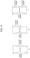
- FIG. 4 illustrates an example of a system bandwidth and a bandwidth supported from the UE in an NR carrier. It is assumed in FIG. 4 that a bandwidth supported from a network is a system bandwidth. However, according to a required system bandwidth, the network may combine an NR carrier. Further, the bandwidth supported from the UE may correspond to the BWP mentioned above.
- FIG. 4-(a) illustrates a case where the system bandwidth is the same as the bandwidth supported from the UE.
- FIG. 4-(b) illustrates a case where the system bandwidth differs from the bandwidth supported from the UE. In FIG. 4-(b) , the bandwidth supported from the UE may be less than the system bandwidth or the bandwidth supported from the UE may be greater than the system bandwidth.
- FIG. 4-(a) illustrates a case where the system bandwidth is the same as the bandwidth supported from the UE.
- FIG. 4-(b) illustrates a case where the system bandwidth differs from the bandwidth supported from the UE.
- the bandwidth supported from the UE may be less than the
- 4-(c) illustrates a case where the UE support a wideband using a plurality of radio frequency (RF) elements. Accordingly, the system bandwidth may be the same as the bandwidth supported from the UE.
- a plurality of RF elements may share a baseband element.
- An individual baseband element may be assigned in a unit of each RF element. It is assumed in the present specification that a plurality of RF elements may share a baseband element/ability. The above may depend on UE ability.
- FIG. 5 illustrates an example of carrier aggregation. If a plurality of NR carrier is aggregated to configure one carrier, the system bandwidth may be changed and a center frequency may be changed. However, a direct current (DC) subcarrier may be changed or may not be changed according to an operation of the network. When the DC subcarrier is changed, the DC subcarrier may be indicated to the UE to suitably process the DC subcarrier.
- DC direct current
- a relationship between an anchor sub-band including an SS block and a sub-band may be changed.
- SS synchronization signal
- PBCH primary synchronization signal/secondary synchronization signal/physical broadcast channel
- the sub-band may correspond to the BWP mentioned above.
- the anchor sub-band may be called another name such as an initial BWP.
- the anchor sub-band may be located at only one of determined sub-bands.
- the size of the sub-band may be determined based on the system bandwidth.
- the anchor sub-band may be located at only one of the sub-bands. For example, if it is assumed that the system bandwidth is 400 MHz and a size of the sub-band is 100 MHz, the anchor sub-band may be located at one of 4 sub-bands.
- the SS block may be located at any position in the anchor sub-band. Meanwhile, if there are different bandwidths supported by the network in the same frequency band, it may be preferred that different bandwidths are arranged.
- a sub-band of 100 MHz may help to arrange different bandwidths between cells at the same frequency band.
- a position of the SS block may be limited.
- the sub-band configuration may be defined per frequency range or per frequency band. For example, when a current LTE frequency band is used an NR frequency band as it is or is shared with an NR frequency band, the number of sub-bands may be 1 and a sub-band size may be the same as a system bandwidth. That is, the sub-band may not be supported from a frequency band equal to or overlapping with an LTE frequency band. Meanwhile, when the NR frequency band is redefined through at least one LTE frequency band, partial UEs may not support the system bandwidth. Accordingly, at the frequency band equal to or overlapping with the LTE frequency band, a sub-band size (e.g. 20 MHz or 10 MHz) fixed according to UE minimum bandwidth requirements or a general UE RF bandwidth may be configured.
- a sub-band size e.g. 20 MHz or 10 MHz
- a position of the SS block may be limited according to the sub-band size. That is, a partial synchronization raster may not be used for mapping of a synchronization signal. It is because the SS block is configured through a sub-band (that is, the SS block is not fully included in one sub-band). Since there is no mapping of the synchronization signal in a corresponding synchronization raster, the UE does not need to discover a corresponding synchronization raster.
- An anchor sub-band may be configured based on initial synchronization. Based on the SS block, it may be assumed that a center of the SS block is a center of the anchor sub-band.
- the anchor sub-band may be implicitly configured.
- the size of the anchor sub-band may be previously determined or may be defined by a master information block (MIB) in the SS block. In this case, when frequencies on which the SS block is transmitted differ from each other between neighbor cells, the sub-band may not be arranged between the neighbor cells. Further, the subcarrier and a RB grid may not be arranged.
- MIB master information block
- An anchor sub-band may be configured separately from another sub-band. That is, a sub-band configuration may be configured based on a system bandwidth or may be pre-configured per frequency range or per frequency band. An anchor sub-band to which the SS block is transmitted may not be associated to a sub-band configuration. Accordingly, the SS block may be transmitted in any place, and the anchor sub-band may be configured to partially or fully overlap with another sub-band.
- FIG. 6 illustrates an example of an anchor sub-band configured separately from another sub-band according to an embodiment of the present disclosure.
- the UE is configured to support 3 sub-bands.
- the anchor sub-band is configured separately from the three sub-bands which are configured.
- an anchor sub-band is configured through a sub-band 1 and a sub-band 2, and an SS block is transmitted through an anchor sub-band.
- a group of sub-bands may be indicated to the UE through group common signaling.
- a plurality of analog beams may be configured to transmit one SS block. After detecting the SS block, it is assumed that the UE uses an optimal combination of beams detected from an SS block to transmit a control channel. The best combination of beams detected from the SS block may be called wide beam. Since there may be a plurality of beams in a wide beam, the same information may be transmitted through different beam. For example, if the UE knows the number of beams in the SS block and detects an optimal beam from a plurality of beams in the wide beam, the UE may monitor only the optimal beam to minimize power consumption for monitoring a control channel.
- the network may configure a CSS and/or a UE-specific search space (USS) and/or a group common SS based on the corresponding information. That is, the network may define a CSI-RS resource in a QCL relationship for a control channel based on the corresponding information. That is, before a CSI-RS configuration, an SS block for control channel monitoring may be implicitly configured to the UE. After the CSI-RS configuration, a QCL CSI-RS resource for control channel monitoring may be indicated to the UE.
- USS UE-specific search space
- the present disclosure describes a method for receiving an SS block including PSS/SSS/PBCH, regarding an initial access procedure and configuration in NR.
- FIG. 7 illustrates an example of receiving an SS block by different UEs according to an embodiment of the present disclosure.
- An initial BWP (or anchor sub-band) including an SS block may be changed based on a UE procedure.
- a BWP1 including an SS block read by UE1 differs from a BWP including an SS block read by UE2, and both of the BWP1 and the BWP is smaller than a system bandwidth.
- a center of the two BWPs is spaced apart from a center of the system bandwidth by another offset.
- a default BWP may be configure to include an SS block according to UE ability. That is, if a UE minimum bandwidth is greater than a sum of an RMSI bandwidth and an SS block bandwidth, a RMSI CORESET and the SS block are continuously multiplexed by frequency division multiplexing (FDM), an initial BWP may cover both of the RMSI CORESET and the SS block. Otherwise, the initial BWP may cover the RMSI CORESET.
- FDM frequency division multiplexing
- the network may reconfigure a default BWP capable of including an SS block and a necessary RMSI CORESET bandwidth in the UE. If the UE reads the SS block, it may be assumed that the SS block bandwidth is a UE bandwidth.
- a PBCH included in the SS block may include at least one of following information.
- following information may be transmitted through RMSI or UE specific signaling as well as a PBCH.
- SCell secondary cell
- An MIB transmitted through a PBCH may include information on an offset between a center of an SS block and a center of a system bandwidth. Since the center of an SS block differs from the center of a system bandwidth, the above information may be indicated by the UE. The above information may be included in a PBCH regardless of whether information on the carrier bandwidth is included in the PBCH. When the information on the carrier bandwidth is included in the PBCH or an RMSI bandwidth is the same as a PBCH bandwidth, the PBCH may include information on an offset between the center of the SS block and the center of the system bandwidth.
- the PBCH may include information on an offset between a center of a PBCH or a RMSI and a center of a system bandwidth instead of the information on offset between the center of the SS block and the center of the system bandwidth.
- an MIB transmitted through the PBCH may also include information on an offset between a PRB of the lowest index of the SS block and a virtual PRB 0.
- the MIB transmitted through the PBCH may include a subcarrier (subcarrier 0) of the lowest index of the SS block and a subcarrier (subcarrier 0) of the lowest index of a common RB.
- Information on an offset between the center of the SS block and the center of the system bandwidth may be expressed as a value with respect to a channel raster (or synchronization raster). If it is assumed that a channel raster is 100 kHz, following options may be considered.
- a channel raster is 240 kHz, or a plurality of subcarriers or at least one RB based on a numerology used for RMSI (or PSS/SSS/PBCH), following options may be considered.
- Information on an offset between a center of an SS block and a center of the system bandwidth may be expressed as a positive value or a negative value according to whether the center of the system bandwidth is higher or lower than the center of the SS block.
- the information on the carrier bandwidth is included in the PBCH
- the information on an offset between a center of an SS block and a center of the system bandwidth may be a maximum bit assuming a maximum bandwidth supported by a carrier.
- the information on an offset between a center of an SS block and/or a RMSI and a center of the system bandwidth, and/or information on an offset between a PRB (or subcarrier) of the lowest index of the SS block and/or the RMSI and a PRB 0 (or subcarrier 0) of the system bandwidth may be indicated to the UE.
- the UE may perform common PRB indexing through the system bandwidth as well as PRB indexing in a BWP configured to the UE (i.e. local PRB indexing).
- a concept of the above local/common PRB indexing is applicable to scrambling of a control signal/data/reference signal (RS) in a BWP of the UE and/or RS generation and/or common data scheduling in an initial CSS. That is, if the UE knows the system bandwidth according to information on the system bandwidth and/or information on an offset between a center of the SS block and a center of the system bandwidth, scrambling of a control signal/data/RS in a BWP of the UE and/or RS generation and/or common data scheduling in an initial CSS may be performed based on the system bandwidth and a common PRB indexing.
- RS control signal/data/reference signal
- a sequence for scrambling of a control signal/data/RS and/or RS generation and/or common data scheduling in an initial CSS is generated across whole PRBs in the system bandwidth. If the UE does not know a system bandwidth, scrambling of the control signal/data/RS in a BWP of the UE and/or RS generation and/or common data scheduling in initial CSS may be performed based on a configured bandwidth (i.e. initial BWP) and local PRB indexing. This means that a sequence for scrambling of the control signal/data/RS and/or RS generation and/or common data scheduling in the initial CSS is generated across PRBs in the BWP.
- a configured bandwidth i.e. initial BWP
- common PRB indexing may be used for scrambling of the control signal/data/RS and/or RS generation and/or common data scheduling.
- RMSI CORESET is shared for another radio network temporary identifier (RNTI) monitoring
- local scrambling/PRB indexing may be used for RMSI control signal/data monitoring
- common scrambling/PRB indexing may be used for monitoring another channel (non-RMSI control signal/data).
- RS sequence related parameters e.g. length, an offset and the like
- Such a method may be applicable to only a case of configuring a wideband. That is, if the wideband is configured, RS sequence related parameters (e.g. length, offset and the like) may be explicitly or implicitly configured per CORESET. For example, when a wideband is used as a default, local scrambling/PRB indexing may be used with respect to RMSI CORESET.
- a similar scheme may be applicable to generation of an RS sequence.
- different RS sequences may be generated/used according to whether the UE knows a common PRB indexing.
- a RMSI PDSCH may use an RS sequence based on local PRB indexing.
- Another PDSCH may use an RS sequence based on common PRB indexing.
- local scrambling/PRB indexing may be used for transmission of all common control signals.
- one of local scrambling/PRB indexing and common scrambling/PRB indexing may be used.
- Common scrambling/PRB indexing may be used to transmit non-common control signal/data such as group common or UE specific signaling.
- Scrambling and/or DM-RS sequence related parameter/configuration may be performed per BWP, and the initial DL/UL BWP may assume local scrambling/PRB indexing. Scrambling of the control signal/data/RS and/or RS generation and/or common data scheduling at initial CSS may be performed based on a maximum system bandwidth.
- the maximum system bandwidth may be defined as K times of an actual maximum system defined per frequency band or per frequency range.
- Resource allocation for data scheduling may be performed based on a configured bandwidth (i.e. initial BWP). That is, regardless of common PRB indexing based on a system bandwidth or a potential maximum system bandwidth, resource allocation for data scheduling may be performed based on local PRB indexing.
- FIG. 8 illustrates a method for performing PRB indexing by UE according to an embodiment of the present disclosure.
- the present disclosure described above may be applicable to this embodiment.
- a UE receives information on an offset between an SS block and a system bandwidth from a network through an SS block.
- the information on the offset may include information on an offset between a PRB of the lowest index of the SS block and a PRB of the lowest index of the system bandwidth.
- the information on the offset may include information on an offset between a subcarrier 0 of the SS block and a subcarrier 0 of the system bandwidth.
- the information on the offset may include information on an offset between a center of the SS block and a center of the system bandwidth.
- the SS block may further include information on the system bandwidth.
- the information on the system information may include information on a potential maximum bandwidth in which a carrier is operated.
- the SS block may be included in an initial UL BWP.
- the information on the offset may be expressed as a value of a channel raster or a synchronization raster.
- the UE may perform the PRB indexing for the system bandwidth based on information on the offset. That is, the UE may perform common PRB indexing. Scrambling of a control signal, data, and a reference signal may be performed based on the PRB indexing for the system bandwidth. Further, the reference signal may be generated based on the PRB indexing for the system bandwidth.
- FIG. 9 illustrates an example of reception of an SS block according to an embodiment of the present disclosure.
- FIG. 9-(a) illustrates a system bandwidth, and a common PRB indexing for PRBs included in the system bandwidth is defined.
- the center of the system bandwidth does not correspond to the center of the SS block. Accordingly, information on an offset between the center of the SS block and the center of the system bandwidth or information on an offset between a PRB of the lowest index of the SS block and a PRB 0 of the system bandwidth may be indicated to the UE. It is assumed in FIG. 9-(a) that a center of the SS block is arranged at a synchronization raster of 15 kHz.
- FIG. 9-(a) illustrates a system bandwidth, and a common PRB indexing for PRBs included in the system bandwidth is defined.
- the center of the system bandwidth does not correspond to the center of the SS block. Accordingly, information on an offset between the center of the SS block and the center of the system
- 9-(b) illustrates a bandwidth configured to the UE, i.e. BWP, and a local PRB indexing for the PRB included in a BWP is defined. Regardless of common PRB indexing, resource allocation for data scheduling may be performed based on local PRB indexing.
- PRB indexing/scrambling according to each control signal/data may be as follows.
- a sequence of a control signal/data/reference signal starts from a center frequency to be indexed to a maximum bandwidth or a maximum PRB index.
- the maximum PRB index may be previously determined, or may be indicated by PBCH/SIB.
- an PRB index close to a center frequency may be close to max_PRB/2. Otherwise, it may be difficult when a UE having different bandwidths shares the same resource for a control signal/data/reference signal.
- a common scrambling/PRB indexing may be used for at least shared control signal/data/reference signal, and a local scrambling/PRB indexing may be used for UE specific shared control signal/data/reference signal.
- CA carrier aggregation
- the UE may be configured with following information.
- a cell may be defined by a combination of a cell ID, a reference point, a reference of the SS block (or difference from the reference point), and a potential maximum bandwidth.
- a configuration/reference CORESET of the default BWP may be used for control channel monitoring.
- a CORESET configuration for the default BWP may follow one of following options.
- a configuration of the BWP may include an associated SS block (may be assumed as an SS block for initial access when it is not given) or a default BWP.
- the configuration of the BWP may include CORESET information capable of being monitored by self BWP scheduling or cross BWP scheduling with a given BWP.
- the UE may be configured with at least one BWP, and at least one BWP may be indicated by a default BWP which is automatically activated upon activation. Further, the UE may be configured with a combination of a cell ID of the SCell, a reference point, and a SCell index (if possible, for example, upon cell activation). Moreover, the UE may be configured with a separate CORESET per each BWP or by a CORESET with respect to at least default BWP. In addition, the UE may be separately configured with respect to a measurement target for SCell.
- a primary SCell In a primary SCell (PSCell), the same configuration as the SCell configuration may be given in a BWP aspect.
- an initial BWP for initial access may be used as a default BWP.
- a default BWP When assistance information from the PCell is considered, a default BWP may be also indicated.
- the UE may assume that the initial access is performed in a default BWP. That is, the default BWP may be indicated for the PSCell, and assistance information for initial access may be located in the default BWP.
- the default BWP needs to include associated CORESET in the same carrier.
- a BWP accessed during an initial access procedure may be regarded as a default BWP.
- a RMSI bandwidth may be regarded as a DL default BWP.
- a RACH bandwidth may be regarded as UL default bandwidth.
- the UL default bandwidth may be the same as the DL default bandwidth (addition to TX-RX or duplex gap). If a frequency in which RAR or MSG4 is received is reconfigured, a default BWP may be automatically changed according to the reconfiguration. That is, according to configuration of RACH procedure related message/CORESET, a default BWP during the initial access procedure may be switched.
- the default BWP is switched from the initial BWP after connection.
- the UE may need to fall back to the initial BWP in which the SS block is firstly acquired.
- a BWP having an SS block for time/frequency synchronization and SS block based measurement may be configured as a fallback BWP. That is, if the UE is switched to an idle state, the default BWP may become an initial BWP or a separate fallback BWP for the purpose of fallback may be configured.
- the BWP may be differently configured per UE for load balance of paging.
- Each BWP may include an SS block which may differ from an initially accessed SS block.
- the UE may maintain that two SS blocks become QCL. That is, if the UE is reconfigured with a BWP different from an initially accessed BWP during RRC connection configuration or idle state, the UE may assume that an initially accessed SS block and the reconfigured SS block have a QCL relationship.
- the QCL relationship may be explicitly indicated.
- the UE may reacquire or perform an initial access procedure. If a new SS block and the initially accessed SS block do not have the QCL relationship, the UE may perform handover.
- An initial BWP may be configured to be activated simultaneously with SCell activation. If it is assumed that measurement is performed before activation, an initial BWP may not be associated with an SS block in a SCell.
- the initial BWP may include an SS block at a PCell.
- the SCell may not include the initial BWP.
- a PSCell needs to include the initial BWP.
- the initial BWP may be regarded as a default BWP before reconfiguration.
- the default BWP may be reconfigured.
- the reconfigured default BWP may not include an SS block. If the reconfigured default BWP includes the SS block, the UE may take into consideration the followings.
- a DL carrier may be associated with a UL carrier having a band different from that of the DL carrier.
- Such a characteristic may be considered according to a following cause.
- the UL carrier corresponds to a UL spectrum in a paired DL/UL spectrum
- activation/inactivation of the UL carrier may be independently performed. Otherwise, the UL carrier may be changed automatically or simultaneously with a DL carrier in the same frequency band. That is, a DL carrier in the same frequency band becomes a main carrier. Accordingly, a UL BWP may be changed.
- a switch command of the UL BWP may be transferred to only the main DL carrier. That is, another DL carrier may depend on the switch command in the main DL carrier.
- another DL carrier may indicate the UL BWP, and the network may select the same BWP between different DL carriers.
- a PUCCH offset may be changed according to change of the UL BWP. Accordingly, if a different DL carrier indicates a different UL BWP at a different time, confusion of the PUCCH resource may be caused. For example, when two UL BWPs are configured and two DL carriers may dynamically indicate switch of a UL BWP, the first DL carrier indicates the UL BWP to switch from a UL BWP 1 to a UL BWP 2, and the UE may fail to receive a corresponding command. In this case, if the second DL carrier transmits a PDSCH, it is ambiguous which PUCCH resource is used.
- a network may monitor both of two PUCCH resources or a scheduling DCI for PDSCH may include PUCCH BWP information as resource indicator. That is, a scheduling DCI for PDSCH may be used to switch a UP BWP.
- DL slots n to n+m may be mapped to an HARQ-ACK of a single PUCCH resource, and a UL BWP carrying the PUCCH may be changed in a middle of DL slots n to n+m.
- switch of the UL BWP carrying a PUCCH during accumulation of HARQ-ACK in a plurality of slots may not be allowed.
- a UL BWP for a new PUCCH during accumulation of HARQ-ACK in a plurality of slots may be used, and a resource selected for a previous UL BWP may be ignored.
- a DCI of the new UL BWP may include a new resource.
- a new resource may be selected. If the UE fails to receive a new resource indication, information on an existing UL BWP may be used. If the UE receives a switch command of the UL BWP after a DCI scheduling the PDSCH, a resource indicated in a corresponding DCI may be used for the new UL BWP.
- a UL BWP carrying the PUCCH and a resource may be dynamically indicated. In this case, this may be used to activate the new UL BWP.
- a DCI indicating a different UL BWP may not be multiplexed in the same PUCCH.
- a configuration of a new UL BWP may be always used.
- one DL carrier includes an associated SUL carrier, and only one of the SUL carrier or the UL carrier in the same band as that of the DL carrier may be activated
- a plurality of BWPs may be configured with respect to each UL carrier, and one BWP may be activated/inactivated.
- a common PRB indexing for the SUL carrier may be performed. For example, information on a center or a reference point of the SUL carrier and information on an offset between the smallest PRBs (virtual PRB) from a center or a reference point of the SUL carrier may be indicated, and a common PRB indexing for the SUL carrier may be performed based thereon.
- the PUCCH resource may be also changed. It may be assumed that the default UL BWP is a UL BWP used for a RACH procedure.
- the default BWP may be reconfigured afterward or the default BWP may be changed according to a PRACH trigger in another carrier or another UL BWP.
- a PRACH resource used for at least PRACH trigger may be configured.
- the trigger message may include a BWP index to switch the UL BWP.
- the UE may perform a RACH procedure at a new initial/default UL BWP afterward. That is, the default UL BWP may be semi-statically or dynamically changed based on the RACH procedure.
- Necessary information associated with a cell ID used at the SUL carrier and a UL carrier in the same band as that of the DL carrier may be same as if the SUL carrier and the UL carrier is included in different BWPs but in the same carrier. That is, UL BWP switch between the SUL carrier and a UL carrier having the same band as that of the DL carrier may be used for switch between two UL carriers.
- a PUCCH carrier/cell and a PRACH carrier/cell may be included in the same carrier. That is, the UE performs the PRACH and a default UL BWP transmitting the PUCCH may be configured in the same UL carrier. That is, with respect to at least PCell, a PUCCH may not be configured in a carrier/cell to which the PRACH is not transmitted. In a case of the SCell, the PUCCH may be configured between 2 UL carriers.
- one DL carrier includes an associated SUL carrier, and both of a SUL carrier and a UL carrier having the same band as that of a DL carrier may be activated
- This case may be regarded as a UL CA including a single DL carrier or a DL CA.
- a different carrier may include only a DL carrier, only a UL carrier, or a paired DL/UL carrier.
- the paired DL/UL carrier and a UL dedicated carrier may be activated.
- At least one activated UL BWP may be configured in the paired DL/UL carrier and the UL dedicated carrier.
- the paired DL/UL carrier does not mean a paired spectrum.
- the paired DL/UL carrier is located at the same frequency.
- the UE may transmit a PRACH in an SUL carrier.
- the SUL carrier may be automatically activated together with the paired UL carrier.
- one of two UL carriers may be selected. Only a selected UL carrier according to an activation message may be activated.
- an additional UL carrier may be activated. In the PCell, this may mean a UL carrier is an activated a UL carrier including a UL BWP in which PRACH transmission is initiated.
- the UL BWP may be activated in both of the SUL carrier and the non-SUL carrier.
- the above procedure is applicable to an initial UL BWP at the PCell.
- the network may indicate the UL BWP to be activated for PUCCH transmission in a PUCCH carrier configuration.
- the UL BWP indicated in the PUCCH carrier configuration may be activated.
- an initial UL BWP configured by an RMSI or a higher layer may be activated in the PUCCH carrier configuration.
- the activated UL BWP may be changed by RRC reconfiguration or DCI switching.
- BWP switching for the SUL carrier may be performed through a UL grant for the SUL carrier. If dynamic PUSCH change is not configured and a SUL carrier is selected as a PUCCH carrier, only DL BWP switching may be possible with respect to a non-paired DL/UL carrier regardless of a BWP pair.
- Signaling suggested in the above description may be transmitted through a common signaling such as RMSI/on-demand SI (OSI) or UE specific signaling and/or DCI.
- OSI on-demand SI
- UE specific signaling and/or DCI may be transmitted through a common signaling such as RMSI/on-demand SI (OSI) or UE specific signaling and/or DCI.
- OSI on-demand SI
- a different signaling may be used.
- a different signal may be used depending on how to define a cell.
- RRC ambiguity may occur. In order to minimize RRC ambiguity, the following may be considered.
- a RMSI CORESET may be called CORESET 0
- a RAR CORESET may be called CORESET 1.
- the CORESET 1 of index 1 may be defined as a special CORESET which may be reused after RRC connection.
- Monitoring SIB/paging may be reconfigured as a CORESET 1 by an RRC configuration.
- a CORESET 1 for RAR configured in an initial DL BWP may have following characteristics.
- the CORESET 1 may be handled differently from the CORESET 0.
- a CORESET configured by an SS block and/or an RMSI may be specially handled. It may be preferred to use a local PRB indexing only before a common PRB indexing is allowed. Accordingly, if a PRB 0 is indicated in a RMSI, a CORESET configured by RMSI and/or UE specific signaling may follow a common PRB indexing.
- the UE may omit monitoring of the CORESET 0. That is, if the CORESET 1 is configured once, the UE may not be requested to monitor the CORESET 0.
- the UE may return an initial DL BWP. Since a paging search space is associated with the CORESET 0, the UE may monitor a search space associated with the CORESET 0. If the UE starts a RACH procedure in an idle state, the UE may monitor the CORESET 1.
- UE monitoring may be considered as follows.
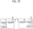
- FIG. 10 shows a block diagram of a wireless communication system to implement an embodiment of the present disclosure.
- An UE 1000 includes a processor 1010, a memory 1020, and a transceiver 1030.
- the memory 1020 is operatively coupled with the processor 1010 and stores a variety of information to operate the processor 1010.
- the transceiver 1030 is operatively coupled with the processor 1010, and transmits and/or receives a radio signal to and from the network node 1100.
- the processor 1010 may be configured to implement proposed functions, procedures and/or methods described in this description. In detail, the processor 1010 may perform steps S800 to S810 in FIG. 8 or control the transceiver 1030 to perform the steps.
- a network node 1100 includes a processor 1110, a memory 1120, and a transceiver 1130.
- the memory 1120 is operatively coupled with the processor 1110 and stores a variety of information to operate the processor 1110.
- the transceiver 1130 is operatively coupled with the processor 1110, and transmits and/or receives a radio signal to and from the UE 1000.
- the processors 1010, 1110 may include application-specific integrated circuit (ASIC), other chipset, logic circuit and/or data processing device.
- the memories 1020, 1120 may include read-only memory (ROM), random access memory (RAM), flash memory, memory card, storage medium and/or other storage device.
- the transceivers 1030, 1130 may include baseband circuitry to process radio frequency signals.
- the techniques described herein can be implemented with modules (e.g., procedures, functions, and so on) that perform the functions described herein.
- the modules can be stored in memories 1020, 1120 and executed by processors 1010, 1110.
- the memories 1020, 1120 can be implemented within the processors 1010, 1110 or external to the processors 1010, 1110 in which case those can be communicatively coupled to the processors 1010, 1110 via various means as is known in the art.
- FIG. 11 illustrates a processor of a UE shown in FIG. 10 .
- the processor 1010 of the UE includes a conversion pre-coder 1011, a subcarrier mapper 1012, an inverse fast Fourier transform (IFFT) unit and a cyclic prefix (CP) insertion unit.
- IFFT inverse fast Fourier transform
- CP cyclic prefix
Landscapes
- Engineering & Computer Science (AREA)
- Signal Processing (AREA)
- Computer Networks & Wireless Communication (AREA)
- Databases & Information Systems (AREA)
- Mobile Radio Communication Systems (AREA)
Claims (13)
- Procédé exécuté par un dispositif sans fil dans un système de communication sans fil, le procédé consistant à :recevoir des informations concernant un décalage entre un bloc de signaux de synchronisation, SS, et une bande passante de système en provenance d'un réseau par le bloc SS ;déterminer un index de bloc de ressource physique, PRB, de la bande passante de système en fonction des informations concernant le décalage ;recevoir une transmission d'un signal de référence en provenance du réseau ; etrecevoir des données en provenance du réseau par l'intermédiaire d'une bande passante spécifique au dispositif sans fil en fonction du signal de référence,dans le cas où les données comprenant des informations système minimum restantes, RMSI, le signal de référence étant traité pour la transmission en fonction d'une indexation PRB pour une région de fréquence partielle dans la bande passante de système, etdans le cas où les données ne comprennent pas les RMSI, le signal de référence étant traité pour la transmission sur la base d'un indexation PRB pour la bande passante de système.
- Procédé selon la revendication 1, les informations concernant le décalage comprenant les informations relatives à un décalage entre un PRB de l'index le plus faible du bloc de SS et un PRB de l'index le plus faible de la bande passante de système.
- Procédé selon la revendication 1, les informations concernant le décalage comprenant des informations concernant un décalage entre une sous-porteuse 0 du bloc SS et une sous-porteuse 0 de la bande passante de système.
- Procédé selon la revendication 1, les informations concernant le décalage comprenant des informations concernant un décalage entre un centre du bloc SS et un centre de la bande passante de système.
- Procédé selon la revendication 1, le bloc SS comprenant en outre des informations concernant la bande passante de système.
- Procédé selon la revendication 5, les informations concernant la bande passante de système comprenant des informations concernant une potentielle bande passante maximum dans laquelle fonctionne une porteuse.
- Procédé selon la revendication selon la revendication 1, le bloc SS étant compris dans une partie de bande passante, BWP, de liaison montante initiale, UL.
- Procédé selon la revendication selon la revendication 1, les informations relatives au décalage étant exprimé sous forme de valeur d'une grille de canaux ou d'une grille de synchronisation.
- Dispositif sans fil (1000) dans un système de communication sans fil, le dispositif sans fil comprenant :une mémoire (1020) ;un émetteur-récepteur (1030) ; etau moins un processeur (1010), couplé fonctionnellement à la mémoire (1020) et à l'émetteur-récepteur (1030), et conçu pour :amener l'émetteur-récepteur (1030) à recevoir des informations relatives à un décalage entre un bloc de signal de synchronisation, SS, et une bande passante de système en provenance d'un réseau par l'intermédiaire du bloc SS,amener l'émetteur-récepteur (1030) à recevoir des données en provenance du réseau par l'intermédiaire d'une bande passante spécifique au dispositif sans fil en fonction du signal de référence,dans le cas où les données comprenant des informations système minimum restantes, RMSI, le signal de référence étant traité pour la transmission en fonction d'une indexation PRB pour une région de fréquence partielle dans la bande passante de système, etdans le cas où les données ne comprennent pas les RMSI, le signal de référence étant traité pour la transmission sur la base d'un indexation PRB pour la bande passante de système.
- Dispositif sans fil selon la revendication 9, les informations relatives au décalage comprenant des informations relatives à un décalage entre un PRB de l'index le plus faible du bloc de SS et un PRB de l'index le plus faible de la bande passante de système.
- Dispositif sans fil selon la revendication 9, les informations relatives au décalage comprenant des informations relatives à un décalage entre une sous-porteuse 0 du bloc SS et un centre de la bande passante de système.
- Dispositif sans fil selon la revendication 9, les informations relatives au décalage comprenant des informations relatives à un décalage entre un centre du bloc SS et un centre de la bande passante de système.
- Dispositif sans fil selon la revendication 9, le bloc SS comprenant en outre des informations relatives à la bande passante de système.
Priority Applications (1)
| Application Number | Priority Date | Filing Date | Title |
|---|---|---|---|
| EP21161712.1A EP3852289A1 (fr) | 2017-04-14 | 2018-04-13 | Procédé et appareil permettant de réaliser une connexion initiale dans un système de communication sans fil |
Applications Claiming Priority (7)
| Application Number | Priority Date | Filing Date | Title |
|---|---|---|---|
| US201762485865P | 2017-04-14 | 2017-04-14 | |
| US201762516120P | 2017-06-07 | 2017-06-07 | |
| US201762560167P | 2017-09-18 | 2017-09-18 | |
| US201762564209P | 2017-09-27 | 2017-09-27 | |
| US201762572534P | 2017-10-15 | 2017-10-15 | |
| US201862630243P | 2018-02-14 | 2018-02-14 | |
| PCT/KR2018/004347 WO2018190678A1 (fr) | 2017-04-14 | 2018-04-13 | Procédé et appareil permettant d'effectuer une connexion initiale dans un système de communication sans fil |
Related Child Applications (2)
| Application Number | Title | Priority Date | Filing Date |
|---|---|---|---|
| EP21161712.1A Division EP3852289A1 (fr) | 2017-04-14 | 2018-04-13 | Procédé et appareil permettant de réaliser une connexion initiale dans un système de communication sans fil |
| EP21161712.1A Division-Into EP3852289A1 (fr) | 2017-04-14 | 2018-04-13 | Procédé et appareil permettant de réaliser une connexion initiale dans un système de communication sans fil |
Publications (3)
| Publication Number | Publication Date |
|---|---|
| EP3595199A1 EP3595199A1 (fr) | 2020-01-15 |
| EP3595199A4 EP3595199A4 (fr) | 2020-04-08 |
| EP3595199B1 true EP3595199B1 (fr) | 2021-06-16 |
Family
ID=64132272
Family Applications (2)
| Application Number | Title | Priority Date | Filing Date |
|---|---|---|---|
| EP21161712.1A Pending EP3852289A1 (fr) | 2017-04-14 | 2018-04-13 | Procédé et appareil permettant de réaliser une connexion initiale dans un système de communication sans fil |
| EP18785078.9A Active EP3595199B1 (fr) | 2017-04-14 | 2018-04-13 | Procédé et appareil permettant d'effectuer une connexion initiale dans un système de communication sans fil |
Family Applications Before (1)
| Application Number | Title | Priority Date | Filing Date |
|---|---|---|---|
| EP21161712.1A Pending EP3852289A1 (fr) | 2017-04-14 | 2018-04-13 | Procédé et appareil permettant de réaliser une connexion initiale dans un système de communication sans fil |
Country Status (5)
| Country | Link |
|---|---|
| US (3) | US10944613B2 (fr) |
| EP (2) | EP3852289A1 (fr) |
| JP (1) | JP7055819B2 (fr) |
| KR (2) | KR101975579B1 (fr) |
| CN (1) | CN110574312B (fr) |
Families Citing this family (54)
| Publication number | Priority date | Publication date | Assignee | Title |
|---|---|---|---|---|
| EP3852289A1 (fr) * | 2017-04-14 | 2021-07-21 | LG Electronics Inc. | Procédé et appareil permettant de réaliser une connexion initiale dans un système de communication sans fil |
| US10887842B2 (en) | 2017-04-17 | 2021-01-05 | Samsung Electronics Co., Ltd. | Method and device for uplink power control |
| KR102383385B1 (ko) * | 2017-04-17 | 2022-04-08 | 삼성전자 주식회사 | 업링크 전력 제어를 위한 방법 및 장치 |
| CN110603757B (zh) * | 2017-05-02 | 2021-11-30 | 三星电子株式会社 | 下一代蜂窝网络中初始接入的方法和装置 |
| JP7001681B2 (ja) * | 2017-05-02 | 2022-01-19 | 株式会社Nttドコモ | 端末、無線通信方法、基地局及びシステム |
| US11470616B2 (en) | 2017-05-04 | 2022-10-11 | Samsung Electronics Co., Ltd. | Bandwidth part configurations for single carrier wideband operations |
| EP3941153B1 (fr) | 2017-05-05 | 2023-06-07 | Samsung Electronics Co., Ltd. | Procédé de transmission de données et équipement réseau prenant en charge une fonction de duplication pdcp |
| CN108990161B (zh) | 2017-05-05 | 2020-03-10 | 华为技术有限公司 | 资源分配的方法、用户设备和网络设备 |
| CN108809587B (zh) * | 2017-05-05 | 2021-06-08 | 华为技术有限公司 | 确定参考信号序列的方法、终端设备、网络设备 |
| US12096292B2 (en) * | 2017-05-05 | 2024-09-17 | Samsung Electronics Co., Ltd. | System, data transmission method and network equipment supporting PDCP duplication function method and device for transferring supplementary uplink carrier configuration information and method and device for performing connection mobility adjustment |
| US10270573B2 (en) * | 2017-05-16 | 2019-04-23 | Qualcomm Incorporated | Techniques and apparatuses for reusing remaining minimum system information configuration bits to signal a synchronization signal block location |
| US11272510B2 (en) * | 2017-05-19 | 2022-03-08 | Qualcomm Incorporated | Channel and sync raster signaling |
| CN108966181B (zh) * | 2017-05-26 | 2021-07-23 | 株式会社Kt | 为新无线电配置关于分量载波的频率资源的方法及其装置 |
| WO2018231005A1 (fr) | 2017-06-15 | 2018-12-20 | Innovative Technology Lab Co., Ltd. | Procédé et appareil pour fonctionnement en bande large dans un système de communication nr |
| JP7119011B2 (ja) * | 2017-06-15 | 2022-08-16 | ホアウェイ・テクノロジーズ・カンパニー・リミテッド | 広帯域コンポーネントキャリアの周波数位置インデックス化 |
| KR102352364B1 (ko) * | 2017-06-15 | 2022-01-18 | 주식회사 아이티엘 | Nr 시스템에서 광대역 동작 방법 및 장치 |
| US11496277B2 (en) | 2017-06-16 | 2022-11-08 | Apple Inc. | Physical resource block indexing for coexistence of narrow band, carrier aggregation, and wide band user equipment in new radio |
| WO2018227617A1 (fr) * | 2017-06-16 | 2018-12-20 | 富士通株式会社 | Procédé d'envoi de signaux, procédé de détection, appareil, et système de communication |
| JPWO2018235248A1 (ja) * | 2017-06-22 | 2020-04-23 | 株式会社Nttドコモ | ユーザ端末及び無線通信方法 |
| CN109714141B (zh) | 2017-08-11 | 2020-01-17 | 华为技术有限公司 | 一种物理资源块prb网格的指示方法及设备 |
| US11178012B2 (en) * | 2017-09-06 | 2021-11-16 | Apple Inc. | Configuration schemes for secondary cell, bandwidth part and physical resource block indexing |
| CN111108796B (zh) | 2017-09-28 | 2024-04-05 | 三星电子株式会社 | 用于在多个带宽部分上执行数据发射和测量的方法和网络节点 |
| US10980007B2 (en) * | 2017-09-29 | 2021-04-13 | Samsung Electronics Co., Ltd | Uplink resource configuration method and apparatus in wireless communication system |
| US11395158B2 (en) * | 2017-10-11 | 2022-07-19 | Ntt Docomo, Inc. | User terminal, base station and radio communication method |
| EP3568946A1 (fr) * | 2017-10-26 | 2019-11-20 | Ofinno, LLC | Temporisateur d'inactivité de partie de bande passante |
| EP4301072A3 (fr) * | 2017-11-15 | 2024-02-21 | Nokia Technologies Oy | Accès aléatoire avec commutateur de partie de bande passante |
| KR102456001B1 (ko) * | 2017-11-16 | 2022-10-19 | 삼성전자주식회사 | 무선 통신 시스템에서 상향링크 캐리어를 통해 데이터를 송수신하기 위한 방법 및 장치 |
| CN109802799A (zh) * | 2017-11-17 | 2019-05-24 | 华为技术有限公司 | 用于多载波通信的载波切换 |
| CN108111444A (zh) * | 2017-11-17 | 2018-06-01 | 中兴通讯股份有限公司 | 信号加扰、解扰方法及装置 |
| US11050598B2 (en) * | 2017-11-28 | 2021-06-29 | Qualcomm Incorporated | Carrier information signaling in a 5G network |
| WO2019160720A1 (fr) * | 2018-02-13 | 2019-08-22 | Idac Holdings, Inc. | Procédés de sélection de ressource sans licence |
| US10419257B2 (en) * | 2018-02-15 | 2019-09-17 | Huawei Technologies Co., Ltd. | OFDM communication system with method for determination of subcarrier offset for OFDM symbol generation |
| US11363630B2 (en) | 2018-03-01 | 2022-06-14 | Qualcomm Incorporated | Bandwidth part (BWP) configuration for subband access in new radio-unlicensed (NR-U) |
| CN110475344B (zh) * | 2018-05-10 | 2021-11-26 | 维沃移动通信有限公司 | 一种随机接入方法、终端及网络设备 |
| AU2019290737B2 (en) * | 2018-06-21 | 2024-05-09 | Guangdong Oppo Mobile Telecommunications Corp., Ltd. | Bandwidth part processing method, terminal device and network device |
| MX2020013703A (es) * | 2018-06-25 | 2021-02-26 | Ericsson Telefon Ab L M | Servicio de activacion celular en un sistema de comunicacion inalambrico. |
| JP7105132B2 (ja) * | 2018-08-06 | 2022-07-22 | Kddi株式会社 | レガシーシステムとの共存を実行するための通信装置、通信方法、及びプログラム |
| CN112823558A (zh) * | 2018-08-09 | 2021-05-18 | 弗劳恩霍夫应用研究促进协会 | Nr v2x资源池设计 |
| US11343735B2 (en) * | 2018-09-25 | 2022-05-24 | Comcast Cable Communications, Llc | Beam configuration for secondary cells |
| CN110972270B (zh) * | 2018-09-28 | 2022-03-04 | 展讯通信(上海)有限公司 | 资源信息的确定方法及装置、存储介质、用户设备 |
| US20210377988A1 (en) * | 2018-11-05 | 2021-12-02 | Apple Inc. | Mechanisms for bandwidth part (bwp) switching in a new radio (nr) network |
| CN111385887B (zh) * | 2018-12-29 | 2023-05-09 | 中兴通讯股份有限公司 | 传输数据的方法、装置、设备和存储介质 |
| US11496264B2 (en) * | 2019-02-15 | 2022-11-08 | Qualcomm Incorporated | Interaction of positioning and media access control procedures |
| CN111757349A (zh) * | 2019-03-29 | 2020-10-09 | 华为技术有限公司 | 一种测量方法及装置 |
| MX2021013434A (es) * | 2019-05-02 | 2022-01-24 | Ericsson Telefon Ab L M | Se?alizacion de capa 1 (l1) para administracion rapida de celulas secundarias (scell). |
| EP4007394A4 (fr) * | 2019-07-24 | 2023-02-01 | Ntt Docomo, Inc. | Terminal et procédé de communication |
| US11672016B2 (en) * | 2019-12-09 | 2023-06-06 | Qualcomm Incorporated | RACH configuration for different power classes |
| CN114339843B (zh) * | 2020-09-27 | 2023-08-15 | 中国移动通信集团浙江有限公司 | 一种基于网络覆盖的锚点问题识别方法和装置 |
| US11770773B2 (en) | 2021-04-09 | 2023-09-26 | Qualcomm Incorporated | Duty cycle configuration for power saving |
| US11924862B2 (en) * | 2021-04-21 | 2024-03-05 | Qualcomm Incorporated | SSB, coreset, SIB signal block for initial access information |
| CN113613290B (zh) * | 2021-08-12 | 2023-06-16 | 中国联合网络通信集团有限公司 | 一种下行数据流传送方法、装置及终端 |
| BR112024002031A2 (pt) | 2021-08-13 | 2024-04-30 | Qualcomm Inc | Configuração de parte de largura de banda (bwp) para posicionamento em um estado inativo |
| WO2023211239A1 (fr) * | 2022-04-28 | 2023-11-02 | 엘지전자 주식회사 | Procédé et dispositif pour la réalisation d'une transmission et d'une réception en liaison montante ou en liaison descendante dans un système de communication sans fil |
| WO2024096630A1 (fr) * | 2022-11-04 | 2024-05-10 | 엘지전자 주식회사 | Procédé d'émission/réception de ssb dans un système de communication sans fil, et dispositif associé |
Family Cites Families (23)
| Publication number | Priority date | Publication date | Assignee | Title |
|---|---|---|---|---|
| KR100925441B1 (ko) | 2008-01-07 | 2009-11-06 | 엘지전자 주식회사 | 분산형 가상자원블록 스케쥴링 방법 |
| KR101611272B1 (ko) * | 2008-11-07 | 2016-04-11 | 엘지전자 주식회사 | 참조 신호 전송 방법 |
| CN101931485B (zh) | 2009-06-19 | 2014-02-12 | 北京三星通信技术研究有限公司 | 一种专用参考信号生成方法和装置 |
| CN102036262A (zh) | 2009-09-25 | 2011-04-27 | 中兴通讯股份有限公司 | 一种下行控制信息的检测方法和装置 |
| KR101754970B1 (ko) * | 2010-01-12 | 2017-07-06 | 삼성전자주식회사 | 무선 통신 시스템의 채널 상태 측정 기준신호 처리 장치 및 방법 |
| WO2014003407A1 (fr) * | 2012-06-25 | 2014-01-03 | 엘지전자 주식회사 | Procédé et équipement d'utilisateur pour recevoir un service en diffusion / multidiffusion, et procédé et station de base pour émettre un service en diffusion / multidiffusion |
| KR101926004B1 (ko) * | 2014-11-07 | 2018-12-06 | 후아웨이 테크놀러지 컴퍼니 리미티드 | 직류 컴포넌트 부반송파 구성 방법 및 장치 |
| WO2016120462A1 (fr) * | 2015-01-30 | 2016-08-04 | Nokia Solutions And Networks Oy | Amélioration de bloc d'informations système pour équipement d'utilisateur de faible complexité et/ou équipement d'utilisateur en mode amélioration de couverture |
| US10728077B2 (en) * | 2015-09-02 | 2020-07-28 | Lg Electronics Inc. | Method and apparatus for performing random access procedure in NB-IoT carrier in wireless communication system |
| US11212760B2 (en) | 2015-09-24 | 2021-12-28 | Qualcomm Incorporated | Common synchronization channel design for narrowband communications |
| US10159097B2 (en) * | 2016-09-30 | 2018-12-18 | Qualcomm Incorporated | Signaling and determination of slot and mini-slot structure |
| US10728927B2 (en) * | 2016-11-11 | 2020-07-28 | FG Innovation Company Limited | Data packet delivery in RRC inactive state |
| EP3934151A1 (fr) * | 2016-11-11 | 2022-01-05 | Motorola Mobility LLC | Détermination d'un emplacement d'un blocs de ressources dans le domaine fréquentiel |
| US10470191B2 (en) | 2016-12-09 | 2019-11-05 | Samsung Electronics Co., Ltd. | Method and apparatus of broadcast signals and channels for system information transmission |
| US10492157B2 (en) * | 2017-01-04 | 2019-11-26 | Samsung Electronics Co., Ltd. | Method and apparatus for system information delivery in advanced wireless systems |
| US10523476B2 (en) | 2017-01-11 | 2019-12-31 | Qualcomm Incorporated | Signal scrambling sequence techniques for wireless communications |
| CN110268640B (zh) * | 2017-02-06 | 2023-11-24 | 诺基亚技术有限公司 | 用于无线网络的多波束寻呼技术 |
| US11019584B2 (en) * | 2017-03-14 | 2021-05-25 | Qualcomm Incorporated | User equipment operation in bandwidth narrower than synchronization signal bandwidth |
| CN110447192A (zh) * | 2017-03-15 | 2019-11-12 | 英特尔Ip公司 | 用于混合自动重传请求确认(harq-ack)反馈的新无线电(nr)物理上行链路控制信道(pucch)资源的确定 |
| EP3602988A1 (fr) * | 2017-03-22 | 2020-02-05 | IDAC Holdings, Inc. | Procédés, appareil, systèmes, architectures et interfaces pour un signal de référence d'informations d'état de canal pour des systèmes de communication sans fil de prochaine génération |
| WO2018187242A1 (fr) * | 2017-04-05 | 2018-10-11 | Intel IP Corporation | Taille de groupage reg et modèle dm-rs destiné à un canal de commande de liaison descendante physique |
| US11134492B2 (en) * | 2017-04-12 | 2021-09-28 | Samsung Electronics Co., Ltd. | Method and apparatus for beam recovery in next generation wireless systems |
| EP3852289A1 (fr) * | 2017-04-14 | 2021-07-21 | LG Electronics Inc. | Procédé et appareil permettant de réaliser une connexion initiale dans un système de communication sans fil |
-
2018
- 2018-04-13 EP EP21161712.1A patent/EP3852289A1/fr active Pending
- 2018-04-13 US US16/064,817 patent/US10944613B2/en active Active
- 2018-04-13 JP JP2019555863A patent/JP7055819B2/ja active Active
- 2018-04-13 CN CN201880028769.0A patent/CN110574312B/zh active Active
- 2018-04-13 EP EP18785078.9A patent/EP3595199B1/fr active Active
- 2018-04-13 KR KR1020180043227A patent/KR101975579B1/ko active IP Right Grant
-
2019
- 2019-04-29 KR KR1020190050080A patent/KR102444331B1/ko active IP Right Grant
-
2021
- 2021-02-05 US US17/168,976 patent/US11695605B2/en active Active
-
2022
- 2022-12-13 US US18/080,157 patent/US11863364B2/en active Active
Non-Patent Citations (1)
| Title |
|---|
| None * |
Also Published As
| Publication number | Publication date |
|---|---|
| US11863364B2 (en) | 2024-01-02 |
| EP3595199A1 (fr) | 2020-01-15 |
| CN110574312B (zh) | 2021-02-09 |
| US20230113223A1 (en) | 2023-04-13 |
| JP2020517181A (ja) | 2020-06-11 |
| JP7055819B2 (ja) | 2022-04-18 |
| US10944613B2 (en) | 2021-03-09 |
| KR20190050312A (ko) | 2019-05-10 |
| KR102444331B1 (ko) | 2022-09-16 |
| US20200274750A1 (en) | 2020-08-27 |
| US20210160120A1 (en) | 2021-05-27 |
| EP3852289A1 (fr) | 2021-07-21 |
| KR101975579B1 (ko) | 2019-05-07 |
| CN110574312A (zh) | 2019-12-13 |
| KR20180116157A (ko) | 2018-10-24 |
| US11695605B2 (en) | 2023-07-04 |
| EP3595199A4 (fr) | 2020-04-08 |
Similar Documents
| Publication | Publication Date | Title |
|---|---|---|
| US11863364B2 (en) | Method and apparatus for performing initial access in wireless communication system | |
| US11445494B2 (en) | Resource allocation for transmissions on unlicensed carriers | |
| US10951377B2 (en) | Method and device for allocating resources in wireless communication system | |
| US11133967B2 (en) | Method of transmitting synchronization signal and apparatus therefor | |
| US20210127367A1 (en) | Method and apparatus for allocating resource in wireless communication system | |
| US10897741B2 (en) | Power sharing based on processing time related to carriers | |
| KR101901955B1 (ko) | 하향링크 채널 수신 방법 및 사용자기기와, 하향링크 채널 전송 방법 및 기지국 | |
| CN107079323B (zh) | 报告信道状态信息的移动台、方法和介质 | |
| KR20190038329A (ko) | 통신 시스템에서 프리엠션의 지시 방법 | |
| CN115380603A (zh) | 资源检索程序 | |
| US20180175982A1 (en) | Method for transmitting d2d signal in wireless communication system and device therefor | |
| CA3198170A1 (fr) | Communication des parametres de liaison laterale | |
| KR20240064576A (ko) | 다중 송수신점을 사용하는 통신 시스템에서 통합 tci 설정 방법 및 장치 |
Legal Events
| Date | Code | Title | Description |
|---|---|---|---|
| STAA | Information on the status of an ep patent application or granted ep patent |
Free format text: STATUS: THE INTERNATIONAL PUBLICATION HAS BEEN MADE |
|
| PUAI | Public reference made under article 153(3) epc to a published international application that has entered the european phase |
Free format text: ORIGINAL CODE: 0009012 |
|
| STAA | Information on the status of an ep patent application or granted ep patent |
Free format text: STATUS: REQUEST FOR EXAMINATION WAS MADE |
|
| 17P | Request for examination filed |
Effective date: 20191009 |
|
| AK | Designated contracting states |
Kind code of ref document: A1 Designated state(s): AL AT BE BG CH CY CZ DE DK EE ES FI FR GB GR HR HU IE IS IT LI LT LU LV MC MK MT NL NO PL PT RO RS SE SI SK SM TR |
|
| AX | Request for extension of the european patent |
Extension state: BA ME |
|
| A4 | Supplementary search report drawn up and despatched |
Effective date: 20200311 |
|
| RIC1 | Information provided on ipc code assigned before grant |
Ipc: H04L 5/00 20060101ALI20200305BHEP Ipc: H04J 11/00 20060101AFI20200305BHEP |
|
| DAV | Request for validation of the european patent (deleted) | ||
| DAX | Request for extension of the european patent (deleted) | ||
| RIC1 | Information provided on ipc code assigned before grant |
Ipc: H04L 5/00 20060101ALI20201030BHEP Ipc: H04J 11/00 20060101AFI20201030BHEP |
|
| GRAP | Despatch of communication of intention to grant a patent |
Free format text: ORIGINAL CODE: EPIDOSNIGR1 |
|
| STAA | Information on the status of an ep patent application or granted ep patent |
Free format text: STATUS: GRANT OF PATENT IS INTENDED |
|
| INTG | Intention to grant announced |
Effective date: 20210104 |
|
| INTG | Intention to grant announced |
Effective date: 20210113 |
|
| GRAS | Grant fee paid |
Free format text: ORIGINAL CODE: EPIDOSNIGR3 |
|
| GRAA | (expected) grant |
Free format text: ORIGINAL CODE: 0009210 |
|
| STAA | Information on the status of an ep patent application or granted ep patent |
Free format text: STATUS: THE PATENT HAS BEEN GRANTED |
|
| AK | Designated contracting states |
Kind code of ref document: B1 Designated state(s): AL AT BE BG CH CY CZ DE DK EE ES FI FR GB GR HR HU IE IS IT LI LT LU LV MC MK MT NL NO PL PT RO RS SE SI SK SM TR |
|
| REG | Reference to a national code |
Ref country code: GB Ref legal event code: FG4D |
|
| REG | Reference to a national code |
Ref country code: CH Ref legal event code: EP |
|
| REG | Reference to a national code |
Ref country code: DE Ref legal event code: R096 Ref document number: 602018018796 Country of ref document: DE |
|
| REG | Reference to a national code |
Ref country code: AT Ref legal event code: REF Ref document number: 1403215 Country of ref document: AT Kind code of ref document: T Effective date: 20210715 |
|
| REG | Reference to a national code |
Ref country code: IE Ref legal event code: FG4D |
|
| REG | Reference to a national code |
Ref country code: LT Ref legal event code: MG9D |
|
| PG25 | Lapsed in a contracting state [announced via postgrant information from national office to epo] |
Ref country code: LT Free format text: LAPSE BECAUSE OF FAILURE TO SUBMIT A TRANSLATION OF THE DESCRIPTION OR TO PAY THE FEE WITHIN THE PRESCRIBED TIME-LIMIT Effective date: 20210616 Ref country code: HR Free format text: LAPSE BECAUSE OF FAILURE TO SUBMIT A TRANSLATION OF THE DESCRIPTION OR TO PAY THE FEE WITHIN THE PRESCRIBED TIME-LIMIT Effective date: 20210616 Ref country code: FI Free format text: LAPSE BECAUSE OF FAILURE TO SUBMIT A TRANSLATION OF THE DESCRIPTION OR TO PAY THE FEE WITHIN THE PRESCRIBED TIME-LIMIT Effective date: 20210616 Ref country code: BG Free format text: LAPSE BECAUSE OF FAILURE TO SUBMIT A TRANSLATION OF THE DESCRIPTION OR TO PAY THE FEE WITHIN THE PRESCRIBED TIME-LIMIT Effective date: 20210916 |
|
| REG | Reference to a national code |
Ref country code: AT Ref legal event code: MK05 Ref document number: 1403215 Country of ref document: AT Kind code of ref document: T Effective date: 20210616 |
|
| REG | Reference to a national code |
Ref country code: NL Ref legal event code: MP Effective date: 20210616 |
|
| PG25 | Lapsed in a contracting state [announced via postgrant information from national office to epo] |
Ref country code: SE Free format text: LAPSE BECAUSE OF FAILURE TO SUBMIT A TRANSLATION OF THE DESCRIPTION OR TO PAY THE FEE WITHIN THE PRESCRIBED TIME-LIMIT Effective date: 20210616 Ref country code: RS Free format text: LAPSE BECAUSE OF FAILURE TO SUBMIT A TRANSLATION OF THE DESCRIPTION OR TO PAY THE FEE WITHIN THE PRESCRIBED TIME-LIMIT Effective date: 20210616 Ref country code: NO Free format text: LAPSE BECAUSE OF FAILURE TO SUBMIT A TRANSLATION OF THE DESCRIPTION OR TO PAY THE FEE WITHIN THE PRESCRIBED TIME-LIMIT Effective date: 20210916 Ref country code: LV Free format text: LAPSE BECAUSE OF FAILURE TO SUBMIT A TRANSLATION OF THE DESCRIPTION OR TO PAY THE FEE WITHIN THE PRESCRIBED TIME-LIMIT Effective date: 20210616 Ref country code: GR Free format text: LAPSE BECAUSE OF FAILURE TO SUBMIT A TRANSLATION OF THE DESCRIPTION OR TO PAY THE FEE WITHIN THE PRESCRIBED TIME-LIMIT Effective date: 20210917 |
|
| PG25 | Lapsed in a contracting state [announced via postgrant information from national office to epo] |
Ref country code: EE Free format text: LAPSE BECAUSE OF FAILURE TO SUBMIT A TRANSLATION OF THE DESCRIPTION OR TO PAY THE FEE WITHIN THE PRESCRIBED TIME-LIMIT Effective date: 20210616 Ref country code: ES Free format text: LAPSE BECAUSE OF FAILURE TO SUBMIT A TRANSLATION OF THE DESCRIPTION OR TO PAY THE FEE WITHIN THE PRESCRIBED TIME-LIMIT Effective date: 20210616 Ref country code: SK Free format text: LAPSE BECAUSE OF FAILURE TO SUBMIT A TRANSLATION OF THE DESCRIPTION OR TO PAY THE FEE WITHIN THE PRESCRIBED TIME-LIMIT Effective date: 20210616 Ref country code: RO Free format text: LAPSE BECAUSE OF FAILURE TO SUBMIT A TRANSLATION OF THE DESCRIPTION OR TO PAY THE FEE WITHIN THE PRESCRIBED TIME-LIMIT Effective date: 20210616 Ref country code: NL Free format text: LAPSE BECAUSE OF FAILURE TO SUBMIT A TRANSLATION OF THE DESCRIPTION OR TO PAY THE FEE WITHIN THE PRESCRIBED TIME-LIMIT Effective date: 20210616 Ref country code: PT Free format text: LAPSE BECAUSE OF FAILURE TO SUBMIT A TRANSLATION OF THE DESCRIPTION OR TO PAY THE FEE WITHIN THE PRESCRIBED TIME-LIMIT Effective date: 20211018 Ref country code: SM Free format text: LAPSE BECAUSE OF FAILURE TO SUBMIT A TRANSLATION OF THE DESCRIPTION OR TO PAY THE FEE WITHIN THE PRESCRIBED TIME-LIMIT Effective date: 20210616 Ref country code: AT Free format text: LAPSE BECAUSE OF FAILURE TO SUBMIT A TRANSLATION OF THE DESCRIPTION OR TO PAY THE FEE WITHIN THE PRESCRIBED TIME-LIMIT Effective date: 20210616 Ref country code: CZ Free format text: LAPSE BECAUSE OF FAILURE TO SUBMIT A TRANSLATION OF THE DESCRIPTION OR TO PAY THE FEE WITHIN THE PRESCRIBED TIME-LIMIT Effective date: 20210616 |
|
| PG25 | Lapsed in a contracting state [announced via postgrant information from national office to epo] |
Ref country code: PL Free format text: LAPSE BECAUSE OF FAILURE TO SUBMIT A TRANSLATION OF THE DESCRIPTION OR TO PAY THE FEE WITHIN THE PRESCRIBED TIME-LIMIT Effective date: 20210616 |
|
| REG | Reference to a national code |
Ref country code: DE Ref legal event code: R097 Ref document number: 602018018796 Country of ref document: DE |
|
| PLBE | No opposition filed within time limit |
Free format text: ORIGINAL CODE: 0009261 |
|
| STAA | Information on the status of an ep patent application or granted ep patent |
Free format text: STATUS: NO OPPOSITION FILED WITHIN TIME LIMIT |
|
| PG25 | Lapsed in a contracting state [announced via postgrant information from national office to epo] |
Ref country code: DK Free format text: LAPSE BECAUSE OF FAILURE TO SUBMIT A TRANSLATION OF THE DESCRIPTION OR TO PAY THE FEE WITHIN THE PRESCRIBED TIME-LIMIT Effective date: 20210616 |
|
| 26N | No opposition filed |
Effective date: 20220317 |
|
| PG25 | Lapsed in a contracting state [announced via postgrant information from national office to epo] |
Ref country code: AL Free format text: LAPSE BECAUSE OF FAILURE TO SUBMIT A TRANSLATION OF THE DESCRIPTION OR TO PAY THE FEE WITHIN THE PRESCRIBED TIME-LIMIT Effective date: 20210616 |
|
| REG | Reference to a national code |
Ref country code: CH Ref legal event code: PL |
|
| REG | Reference to a national code |
Ref country code: BE Ref legal event code: MM Effective date: 20220430 |
|
| PG25 | Lapsed in a contracting state [announced via postgrant information from national office to epo] |
Ref country code: MC Free format text: LAPSE BECAUSE OF FAILURE TO SUBMIT A TRANSLATION OF THE DESCRIPTION OR TO PAY THE FEE WITHIN THE PRESCRIBED TIME-LIMIT Effective date: 20210616 Ref country code: LU Free format text: LAPSE BECAUSE OF NON-PAYMENT OF DUE FEES Effective date: 20220413 Ref country code: LI Free format text: LAPSE BECAUSE OF NON-PAYMENT OF DUE FEES Effective date: 20220430 Ref country code: CH Free format text: LAPSE BECAUSE OF NON-PAYMENT OF DUE FEES Effective date: 20220430 |
|
| PG25 | Lapsed in a contracting state [announced via postgrant information from national office to epo] |
Ref country code: BE Free format text: LAPSE BECAUSE OF NON-PAYMENT OF DUE FEES Effective date: 20220430 |
|
| PG25 | Lapsed in a contracting state [announced via postgrant information from national office to epo] |
Ref country code: IE Free format text: LAPSE BECAUSE OF NON-PAYMENT OF DUE FEES Effective date: 20220413 |
|
| P01 | Opt-out of the competence of the unified patent court (upc) registered |
Effective date: 20230527 |
|
| PG25 | Lapsed in a contracting state [announced via postgrant information from national office to epo] |
Ref country code: MK Free format text: LAPSE BECAUSE OF FAILURE TO SUBMIT A TRANSLATION OF THE DESCRIPTION OR TO PAY THE FEE WITHIN THE PRESCRIBED TIME-LIMIT Effective date: 20210616 Ref country code: CY Free format text: LAPSE BECAUSE OF FAILURE TO SUBMIT A TRANSLATION OF THE DESCRIPTION OR TO PAY THE FEE WITHIN THE PRESCRIBED TIME-LIMIT Effective date: 20210616 |
|
| PGFP | Annual fee paid to national office [announced via postgrant information from national office to epo] |
Ref country code: GB Payment date: 20240305 Year of fee payment: 7 |
|
| PG25 | Lapsed in a contracting state [announced via postgrant information from national office to epo] |
Ref country code: HU Free format text: LAPSE BECAUSE OF FAILURE TO SUBMIT A TRANSLATION OF THE DESCRIPTION OR TO PAY THE FEE WITHIN THE PRESCRIBED TIME-LIMIT; INVALID AB INITIO Effective date: 20180413 |
|
| PGFP | Annual fee paid to national office [announced via postgrant information from national office to epo] |
Ref country code: IT Payment date: 20240307 Year of fee payment: 7 Ref country code: FR Payment date: 20240306 Year of fee payment: 7 |
|
| PG25 | Lapsed in a contracting state [announced via postgrant information from national office to epo] |
Ref country code: TR Free format text: LAPSE BECAUSE OF FAILURE TO SUBMIT A TRANSLATION OF THE DESCRIPTION OR TO PAY THE FEE WITHIN THE PRESCRIBED TIME-LIMIT Effective date: 20210616 |
|
| PGFP | Annual fee paid to national office [announced via postgrant information from national office to epo] |
Ref country code: DE Payment date: 20240305 Year of fee payment: 7 |