EP3595075A1 - Secondary battery - Google Patents
Secondary battery Download PDFInfo
- Publication number
- EP3595075A1 EP3595075A1 EP17899847.2A EP17899847A EP3595075A1 EP 3595075 A1 EP3595075 A1 EP 3595075A1 EP 17899847 A EP17899847 A EP 17899847A EP 3595075 A1 EP3595075 A1 EP 3595075A1
- Authority
- EP
- European Patent Office
- Prior art keywords
- active material
- negative electrode
- material region
- positive electrode
- secondary battery
- Prior art date
- Legal status (The legal status is an assumption and is not a legal conclusion. Google has not performed a legal analysis and makes no representation as to the accuracy of the status listed.)
- Granted
Links
- 239000011149 active material Substances 0.000 claims abstract description 90
- 239000007773 negative electrode material Substances 0.000 claims abstract description 44
- 239000007774 positive electrode material Substances 0.000 claims description 29
- 238000010248 power generation Methods 0.000 claims description 15
- 239000003792 electrolyte Substances 0.000 claims description 14
- 230000007704 transition Effects 0.000 claims description 14
- 229910052710 silicon Inorganic materials 0.000 claims description 13
- 239000010703 silicon Substances 0.000 claims description 13
- 230000007423 decrease Effects 0.000 claims description 3
- 239000011887 silicon containing negative electrode material Substances 0.000 abstract 1
- 230000004048 modification Effects 0.000 description 25
- 238000012986 modification Methods 0.000 description 25
- XUIMIQQOPSSXEZ-UHFFFAOYSA-N Silicon Chemical compound [Si] XUIMIQQOPSSXEZ-UHFFFAOYSA-N 0.000 description 13
- PXHVJJICTQNCMI-UHFFFAOYSA-N Nickel Chemical compound [Ni] PXHVJJICTQNCMI-UHFFFAOYSA-N 0.000 description 12
- 239000000463 material Substances 0.000 description 11
- 238000007599 discharging Methods 0.000 description 9
- -1 polypropylene Polymers 0.000 description 8
- OKTJSMMVPCPJKN-UHFFFAOYSA-N Carbon Chemical compound [C] OKTJSMMVPCPJKN-UHFFFAOYSA-N 0.000 description 7
- HBBGRARXTFLTSG-UHFFFAOYSA-N Lithium ion Chemical compound [Li+] HBBGRARXTFLTSG-UHFFFAOYSA-N 0.000 description 7
- 239000011230 binding agent Substances 0.000 description 7
- 229910001416 lithium ion Inorganic materials 0.000 description 7
- RYGMFSIKBFXOCR-UHFFFAOYSA-N Copper Chemical compound [Cu] RYGMFSIKBFXOCR-UHFFFAOYSA-N 0.000 description 6
- VYPSYNLAJGMNEJ-UHFFFAOYSA-N Silicium dioxide Chemical compound O=[Si]=O VYPSYNLAJGMNEJ-UHFFFAOYSA-N 0.000 description 6
- 229910052782 aluminium Inorganic materials 0.000 description 6
- XAGFODPZIPBFFR-UHFFFAOYSA-N aluminium Chemical compound [Al] XAGFODPZIPBFFR-UHFFFAOYSA-N 0.000 description 6
- 239000011883 electrode binding agent Substances 0.000 description 6
- 229910052751 metal Inorganic materials 0.000 description 6
- 239000002184 metal Substances 0.000 description 6
- 229910052759 nickel Inorganic materials 0.000 description 6
- 239000004743 Polypropylene Substances 0.000 description 5
- 230000008602 contraction Effects 0.000 description 5
- 229910052802 copper Inorganic materials 0.000 description 5
- 239000010949 copper Substances 0.000 description 5
- 230000000694 effects Effects 0.000 description 5
- 229920001155 polypropylene Polymers 0.000 description 5
- 239000002033 PVDF binder Substances 0.000 description 4
- RTAQQCXQSZGOHL-UHFFFAOYSA-N Titanium Chemical compound [Ti] RTAQQCXQSZGOHL-UHFFFAOYSA-N 0.000 description 4
- 239000000654 additive Substances 0.000 description 4
- 229910045601 alloy Inorganic materials 0.000 description 4
- 239000000956 alloy Substances 0.000 description 4
- 230000008859 change Effects 0.000 description 4
- 239000011244 liquid electrolyte Substances 0.000 description 4
- 239000000203 mixture Substances 0.000 description 4
- 229920000642 polymer Polymers 0.000 description 4
- 229920002981 polyvinylidene fluoride Polymers 0.000 description 4
- 229910052814 silicon oxide Inorganic materials 0.000 description 4
- 239000002210 silicon-based material Substances 0.000 description 4
- 239000010936 titanium Substances 0.000 description 4
- 229910052719 titanium Inorganic materials 0.000 description 4
- 229920002134 Carboxymethyl cellulose Polymers 0.000 description 3
- 239000004698 Polyethylene Substances 0.000 description 3
- 229910000676 Si alloy Inorganic materials 0.000 description 3
- 239000006230 acetylene black Substances 0.000 description 3
- 238000005253 cladding Methods 0.000 description 3
- 230000003247 decreasing effect Effects 0.000 description 3
- 239000005001 laminate film Substances 0.000 description 3
- 229920000573 polyethylene Polymers 0.000 description 3
- 239000002861 polymer material Substances 0.000 description 3
- 229920000098 polyolefin Polymers 0.000 description 3
- 239000011148 porous material Substances 0.000 description 3
- 239000002904 solvent Substances 0.000 description 3
- 239000010935 stainless steel Substances 0.000 description 3
- 229910001220 stainless steel Inorganic materials 0.000 description 3
- 229920003048 styrene butadiene rubber Polymers 0.000 description 3
- ZZXUZKXVROWEIF-UHFFFAOYSA-N 1,2-butylene carbonate Chemical compound CCC1COC(=O)O1 ZZXUZKXVROWEIF-UHFFFAOYSA-N 0.000 description 2
- VAYTZRYEBVHVLE-UHFFFAOYSA-N 1,3-dioxol-2-one Chemical compound O=C1OC=CO1 VAYTZRYEBVHVLE-UHFFFAOYSA-N 0.000 description 2
- OIFBSDVPJOWBCH-UHFFFAOYSA-N Diethyl carbonate Chemical compound CCOC(=O)OCC OIFBSDVPJOWBCH-UHFFFAOYSA-N 0.000 description 2
- KMTRUDSVKNLOMY-UHFFFAOYSA-N Ethylene carbonate Chemical group O=C1OCCO1 KMTRUDSVKNLOMY-UHFFFAOYSA-N 0.000 description 2
- XEEYBQQBJWHFJM-UHFFFAOYSA-N Iron Chemical compound [Fe] XEEYBQQBJWHFJM-UHFFFAOYSA-N 0.000 description 2
- 229910015020 LiNiCoAlO2 Inorganic materials 0.000 description 2
- WHXSMMKQMYFTQS-UHFFFAOYSA-N Lithium Chemical compound [Li] WHXSMMKQMYFTQS-UHFFFAOYSA-N 0.000 description 2
- FYYHWMGAXLPEAU-UHFFFAOYSA-N Magnesium Chemical compound [Mg] FYYHWMGAXLPEAU-UHFFFAOYSA-N 0.000 description 2
- 229920003171 Poly (ethylene oxide) Polymers 0.000 description 2
- 239000004642 Polyimide Substances 0.000 description 2
- ATJFFYVFTNAWJD-UHFFFAOYSA-N Tin Chemical compound [Sn] ATJFFYVFTNAWJD-UHFFFAOYSA-N 0.000 description 2
- HCHKCACWOHOZIP-UHFFFAOYSA-N Zinc Chemical compound [Zn] HCHKCACWOHOZIP-UHFFFAOYSA-N 0.000 description 2
- 229920003235 aromatic polyamide Polymers 0.000 description 2
- 239000002134 carbon nanofiber Substances 0.000 description 2
- 239000003575 carbonaceous material Substances 0.000 description 2
- 229920001940 conductive polymer Polymers 0.000 description 2
- 239000000470 constituent Substances 0.000 description 2
- JBTWLSYIZRCDFO-UHFFFAOYSA-N ethyl methyl carbonate Chemical compound CCOC(=O)OC JBTWLSYIZRCDFO-UHFFFAOYSA-N 0.000 description 2
- 239000000945 filler Substances 0.000 description 2
- 229910002804 graphite Inorganic materials 0.000 description 2
- 239000010439 graphite Substances 0.000 description 2
- 238000005304 joining Methods 0.000 description 2
- 229910052744 lithium Inorganic materials 0.000 description 2
- 229910003002 lithium salt Inorganic materials 0.000 description 2
- 159000000002 lithium salts Chemical class 0.000 description 2
- 229910052749 magnesium Inorganic materials 0.000 description 2
- 239000011777 magnesium Substances 0.000 description 2
- 239000011159 matrix material Substances 0.000 description 2
- 238000000034 method Methods 0.000 description 2
- KKQAVHGECIBFRQ-UHFFFAOYSA-N methyl propyl carbonate Chemical compound CCCOC(=O)OC KKQAVHGECIBFRQ-UHFFFAOYSA-N 0.000 description 2
- 239000004745 nonwoven fabric Substances 0.000 description 2
- 230000002093 peripheral effect Effects 0.000 description 2
- 229920001721 polyimide Polymers 0.000 description 2
- 239000005518 polymer electrolyte Substances 0.000 description 2
- 229920001451 polypropylene glycol Polymers 0.000 description 2
- RUOJZAUFBMNUDX-UHFFFAOYSA-N propylene carbonate Chemical compound CC1COC(=O)O1 RUOJZAUFBMNUDX-UHFFFAOYSA-N 0.000 description 2
- 229920005989 resin Polymers 0.000 description 2
- 239000011347 resin Substances 0.000 description 2
- 230000000717 retained effect Effects 0.000 description 2
- 150000003377 silicon compounds Chemical class 0.000 description 2
- LIVNPJMFVYWSIS-UHFFFAOYSA-N silicon monoxide Chemical compound [Si-]#[O+] LIVNPJMFVYWSIS-UHFFFAOYSA-N 0.000 description 2
- 229910052718 tin Inorganic materials 0.000 description 2
- 239000011135 tin Substances 0.000 description 2
- 229910052720 vanadium Inorganic materials 0.000 description 2
- LEONUFNNVUYDNQ-UHFFFAOYSA-N vanadium atom Chemical compound [V] LEONUFNNVUYDNQ-UHFFFAOYSA-N 0.000 description 2
- 238000003466 welding Methods 0.000 description 2
- 229910052725 zinc Inorganic materials 0.000 description 2
- 239000011701 zinc Substances 0.000 description 2
- QTBSBXVTEAMEQO-UHFFFAOYSA-M Acetate Chemical compound CC([O-])=O QTBSBXVTEAMEQO-UHFFFAOYSA-M 0.000 description 1
- 229920000049 Carbon (fiber) Polymers 0.000 description 1
- 229920000742 Cotton Polymers 0.000 description 1
- 229910007003 Li(C2F5SO2)2 Inorganic materials 0.000 description 1
- 229910001560 Li(CF3SO2)2N Inorganic materials 0.000 description 1
- 229910000552 LiCF3SO3 Inorganic materials 0.000 description 1
- 229910032387 LiCoO2 Inorganic materials 0.000 description 1
- 229910052493 LiFePO4 Inorganic materials 0.000 description 1
- 229910003005 LiNiO2 Inorganic materials 0.000 description 1
- 229910001290 LiPF6 Inorganic materials 0.000 description 1
- 229910012464 LiTaF6 Inorganic materials 0.000 description 1
- 229910002097 Lithium manganese(III,IV) oxide Inorganic materials 0.000 description 1
- 229920000297 Rayon Polymers 0.000 description 1
- 229910008350 Si-Sn-Ti Inorganic materials 0.000 description 1
- 229910006721 Si—Sn—Ti Inorganic materials 0.000 description 1
- 230000002411 adverse Effects 0.000 description 1
- JRBRVDCKNXZZGH-UHFFFAOYSA-N alumane;copper Chemical compound [AlH3].[Cu] JRBRVDCKNXZZGH-UHFFFAOYSA-N 0.000 description 1
- 229910021486 amorphous silicon dioxide Inorganic materials 0.000 description 1
- 230000004888 barrier function Effects 0.000 description 1
- 229910052799 carbon Inorganic materials 0.000 description 1
- 239000004917 carbon fiber Substances 0.000 description 1
- 230000015556 catabolic process Effects 0.000 description 1
- 229910052681 coesite Inorganic materials 0.000 description 1
- 229920001577 copolymer Polymers 0.000 description 1
- 239000011889 copper foil Substances 0.000 description 1
- 229910052906 cristobalite Inorganic materials 0.000 description 1
- 238000006731 degradation reaction Methods 0.000 description 1
- IEJIGPNLZYLLBP-UHFFFAOYSA-N dimethyl carbonate Chemical compound COC(=O)OC IEJIGPNLZYLLBP-UHFFFAOYSA-N 0.000 description 1
- 229920001971 elastomer Polymers 0.000 description 1
- 238000003411 electrode reaction Methods 0.000 description 1
- 238000005516 engineering process Methods 0.000 description 1
- 230000007613 environmental effect Effects 0.000 description 1
- 230000004927 fusion Effects 0.000 description 1
- 239000003365 glass fiber Substances 0.000 description 1
- 150000002500 ions Chemical class 0.000 description 1
- 229910052742 iron Inorganic materials 0.000 description 1
- 229910001540 lithium hexafluoroarsenate(V) Inorganic materials 0.000 description 1
- MHCFAGZWMAWTNR-UHFFFAOYSA-M lithium perchlorate Chemical compound [Li+].[O-]Cl(=O)(=O)=O MHCFAGZWMAWTNR-UHFFFAOYSA-M 0.000 description 1
- 229910001486 lithium perchlorate Inorganic materials 0.000 description 1
- 229910001496 lithium tetrafluoroborate Inorganic materials 0.000 description 1
- 238000003754 machining Methods 0.000 description 1
- 239000002905 metal composite material Substances 0.000 description 1
- 150000002739 metals Chemical class 0.000 description 1
- 229910001317 nickel manganese cobalt oxide (NMC) Inorganic materials 0.000 description 1
- 229920001778 nylon Polymers 0.000 description 1
- 125000004430 oxygen atom Chemical group O* 0.000 description 1
- 239000002245 particle Substances 0.000 description 1
- 229920005569 poly(vinylidene fluoride-co-hexafluoropropylene) Polymers 0.000 description 1
- 229920000728 polyester Polymers 0.000 description 1
- 239000002964 rayon Substances 0.000 description 1
- 230000004044 response Effects 0.000 description 1
- 239000005060 rubber Substances 0.000 description 1
- 239000004065 semiconductor Substances 0.000 description 1
- 230000035939 shock Effects 0.000 description 1
- 239000000377 silicon dioxide Substances 0.000 description 1
- 239000011856 silicon-based particle Substances 0.000 description 1
- 229910052682 stishovite Inorganic materials 0.000 description 1
- 239000003115 supporting electrolyte Substances 0.000 description 1
- 229920005992 thermoplastic resin Polymers 0.000 description 1
- 229910052905 tridymite Inorganic materials 0.000 description 1
- 229920003169 water-soluble polymer Polymers 0.000 description 1
- 239000013585 weight reducing agent Substances 0.000 description 1
Images


Classifications
-
- H—ELECTRICITY
- H01—ELECTRIC ELEMENTS
- H01M—PROCESSES OR MEANS, e.g. BATTERIES, FOR THE DIRECT CONVERSION OF CHEMICAL ENERGY INTO ELECTRICAL ENERGY
- H01M10/00—Secondary cells; Manufacture thereof
- H01M10/05—Accumulators with non-aqueous electrolyte
- H01M10/052—Li-accumulators
-
- H—ELECTRICITY
- H01—ELECTRIC ELEMENTS
- H01M—PROCESSES OR MEANS, e.g. BATTERIES, FOR THE DIRECT CONVERSION OF CHEMICAL ENERGY INTO ELECTRICAL ENERGY
- H01M10/00—Secondary cells; Manufacture thereof
- H01M10/05—Accumulators with non-aqueous electrolyte
- H01M10/052—Li-accumulators
- H01M10/0525—Rocking-chair batteries, i.e. batteries with lithium insertion or intercalation in both electrodes; Lithium-ion batteries
-
- H—ELECTRICITY
- H01—ELECTRIC ELEMENTS
- H01M—PROCESSES OR MEANS, e.g. BATTERIES, FOR THE DIRECT CONVERSION OF CHEMICAL ENERGY INTO ELECTRICAL ENERGY
- H01M10/00—Secondary cells; Manufacture thereof
- H01M10/05—Accumulators with non-aqueous electrolyte
- H01M10/058—Construction or manufacture
- H01M10/0585—Construction or manufacture of accumulators having only flat construction elements, i.e. flat positive electrodes, flat negative electrodes and flat separators
-
- H—ELECTRICITY
- H01—ELECTRIC ELEMENTS
- H01M—PROCESSES OR MEANS, e.g. BATTERIES, FOR THE DIRECT CONVERSION OF CHEMICAL ENERGY INTO ELECTRICAL ENERGY
- H01M4/00—Electrodes
- H01M4/02—Electrodes composed of, or comprising, active material
- H01M4/13—Electrodes for accumulators with non-aqueous electrolyte, e.g. for lithium-accumulators; Processes of manufacture thereof
- H01M4/131—Electrodes based on mixed oxides or hydroxides, or on mixtures of oxides or hydroxides, e.g. LiCoOx
-
- H—ELECTRICITY
- H01—ELECTRIC ELEMENTS
- H01M—PROCESSES OR MEANS, e.g. BATTERIES, FOR THE DIRECT CONVERSION OF CHEMICAL ENERGY INTO ELECTRICAL ENERGY
- H01M4/00—Electrodes
- H01M4/02—Electrodes composed of, or comprising, active material
- H01M4/13—Electrodes for accumulators with non-aqueous electrolyte, e.g. for lithium-accumulators; Processes of manufacture thereof
- H01M4/134—Electrodes based on metals, Si or alloys
-
- H—ELECTRICITY
- H01—ELECTRIC ELEMENTS
- H01M—PROCESSES OR MEANS, e.g. BATTERIES, FOR THE DIRECT CONVERSION OF CHEMICAL ENERGY INTO ELECTRICAL ENERGY
- H01M4/00—Electrodes
- H01M4/02—Electrodes composed of, or comprising, active material
- H01M4/36—Selection of substances as active materials, active masses, active liquids
- H01M4/38—Selection of substances as active materials, active masses, active liquids of elements or alloys
- H01M4/386—Silicon or alloys based on silicon
-
- H—ELECTRICITY
- H01—ELECTRIC ELEMENTS
- H01M—PROCESSES OR MEANS, e.g. BATTERIES, FOR THE DIRECT CONVERSION OF CHEMICAL ENERGY INTO ELECTRICAL ENERGY
- H01M4/00—Electrodes
- H01M4/02—Electrodes composed of, or comprising, active material
- H01M4/36—Selection of substances as active materials, active masses, active liquids
- H01M4/48—Selection of substances as active materials, active masses, active liquids of inorganic oxides or hydroxides
- H01M4/483—Selection of substances as active materials, active masses, active liquids of inorganic oxides or hydroxides for non-aqueous cells
-
- H—ELECTRICITY
- H01—ELECTRIC ELEMENTS
- H01M—PROCESSES OR MEANS, e.g. BATTERIES, FOR THE DIRECT CONVERSION OF CHEMICAL ENERGY INTO ELECTRICAL ENERGY
- H01M4/00—Electrodes
- H01M4/02—Electrodes composed of, or comprising, active material
- H01M4/64—Carriers or collectors
- H01M4/70—Carriers or collectors characterised by shape or form
-
- H—ELECTRICITY
- H01—ELECTRIC ELEMENTS
- H01M—PROCESSES OR MEANS, e.g. BATTERIES, FOR THE DIRECT CONVERSION OF CHEMICAL ENERGY INTO ELECTRICAL ENERGY
- H01M50/00—Constructional details or processes of manufacture of the non-active parts of electrochemical cells other than fuel cells, e.g. hybrid cells
- H01M50/50—Current conducting connections for cells or batteries
- H01M50/531—Electrode connections inside a battery casing
-
- H—ELECTRICITY
- H01—ELECTRIC ELEMENTS
- H01M—PROCESSES OR MEANS, e.g. BATTERIES, FOR THE DIRECT CONVERSION OF CHEMICAL ENERGY INTO ELECTRICAL ENERGY
- H01M10/00—Secondary cells; Manufacture thereof
- H01M10/04—Construction or manufacture in general
-
- H—ELECTRICITY
- H01—ELECTRIC ELEMENTS
- H01M—PROCESSES OR MEANS, e.g. BATTERIES, FOR THE DIRECT CONVERSION OF CHEMICAL ENERGY INTO ELECTRICAL ENERGY
- H01M2220/00—Batteries for particular applications
- H01M2220/20—Batteries in motive systems, e.g. vehicle, ship, plane
-
- Y—GENERAL TAGGING OF NEW TECHNOLOGICAL DEVELOPMENTS; GENERAL TAGGING OF CROSS-SECTIONAL TECHNOLOGIES SPANNING OVER SEVERAL SECTIONS OF THE IPC; TECHNICAL SUBJECTS COVERED BY FORMER USPC CROSS-REFERENCE ART COLLECTIONS [XRACs] AND DIGESTS
- Y02—TECHNOLOGIES OR APPLICATIONS FOR MITIGATION OR ADAPTATION AGAINST CLIMATE CHANGE
- Y02E—REDUCTION OF GREENHOUSE GAS [GHG] EMISSIONS, RELATED TO ENERGY GENERATION, TRANSMISSION OR DISTRIBUTION
- Y02E60/00—Enabling technologies; Technologies with a potential or indirect contribution to GHG emissions mitigation
- Y02E60/10—Energy storage using batteries
-
- Y—GENERAL TAGGING OF NEW TECHNOLOGICAL DEVELOPMENTS; GENERAL TAGGING OF CROSS-SECTIONAL TECHNOLOGIES SPANNING OVER SEVERAL SECTIONS OF THE IPC; TECHNICAL SUBJECTS COVERED BY FORMER USPC CROSS-REFERENCE ART COLLECTIONS [XRACs] AND DIGESTS
- Y02—TECHNOLOGIES OR APPLICATIONS FOR MITIGATION OR ADAPTATION AGAINST CLIMATE CHANGE
- Y02P—CLIMATE CHANGE MITIGATION TECHNOLOGIES IN THE PRODUCTION OR PROCESSING OF GOODS
- Y02P70/00—Climate change mitigation technologies in the production process for final industrial or consumer products
- Y02P70/50—Manufacturing or production processes characterised by the final manufactured product
-
- Y—GENERAL TAGGING OF NEW TECHNOLOGICAL DEVELOPMENTS; GENERAL TAGGING OF CROSS-SECTIONAL TECHNOLOGIES SPANNING OVER SEVERAL SECTIONS OF THE IPC; TECHNICAL SUBJECTS COVERED BY FORMER USPC CROSS-REFERENCE ART COLLECTIONS [XRACs] AND DIGESTS
- Y02—TECHNOLOGIES OR APPLICATIONS FOR MITIGATION OR ADAPTATION AGAINST CLIMATE CHANGE
- Y02T—CLIMATE CHANGE MITIGATION TECHNOLOGIES RELATED TO TRANSPORTATION
- Y02T10/00—Road transport of goods or passengers
- Y02T10/60—Other road transportation technologies with climate change mitigation effect
- Y02T10/70—Energy storage systems for electromobility, e.g. batteries
Landscapes
- Chemical & Material Sciences (AREA)
- Chemical Kinetics & Catalysis (AREA)
- Electrochemistry (AREA)
- General Chemical & Material Sciences (AREA)
- Engineering & Computer Science (AREA)
- Materials Engineering (AREA)
- Manufacturing & Machinery (AREA)
- Inorganic Chemistry (AREA)
- Battery Electrode And Active Subsutance (AREA)
- Secondary Cells (AREA)
- Cell Electrode Carriers And Collectors (AREA)
- Connection Of Batteries Or Terminals (AREA)
Abstract
Description
- The present invention relates to a secondary battery.
- A secondary battery has at least one power generation element. The power generation element has a positive electrode having a collector on which a positive electrode active material layer is disposed, an electrolyte layer for retaining an electrolyte, and a negative electrode having a collector on which a negative electrode active material layer is disposed. The negative electrode collector has an active material region in which the negative electrode active material layer is disposed, and a non-active-material region in which the negative electrode active material layer is not disposed.
- In recent years, a negative electrode active material containing silicon has been applied in the negative electrode active material layer for the purpose of increasing capacity (see
Patent Document 1, for example). - Patent Document 1: International Publication No.
WO 01/029918 - However, silicon undergoes a change in volume in response to charging and discharging of the secondary battery. Expansion and contraction therefore occur in the silicon-containing active material region, and expansion and contraction does not occur in the non-active-material region, which does not contain silicon.
- This expansion and contraction results in a problem of stress due to a dimensional difference in expansion and contraction between the active material region and the non-active-material region of the negative electrode, and of wrinkling originating at a boundary of the non-active-material region and the active material region. For example, the wrinkling grows as a result of repeated charging and discharging of the secondary battery, and the wrinkling reaches a site (i.e., a portion facing the positive electrode) where electrode reactions occur, and causes an inter-electrode distance between the positive electrode and the negative electrode to become nonuniform. As a result, cycle characteristics (service life) could be adversely affected.
- The present invention was contrived in order to overcome the problems of the prior art described above. An object of the present invention is to provide a secondary battery in which it is possible to suppress wrinkling originating at the boundary of the non-active-material region and the active material region in the negative electrode.
- The present invention for achieving the abovementioned object is a secondary battery comprising a negative electrode having a negative electrode collector on which is disposed a negative electrode active material layer having a negative electrode active material containing silicon, the negative electrode collector having an active material region in which the negative electrode active material layer is disposed, a non-active-material region in which the negative electrode active material layer is not disposed, and a slit extending from the non-active-material region to the active material region.
- In the present invention, the slit extending from the non-active-material region to the active material region relieves stress that occurs in the negative electrode during charging and discharging of the secondary battery. Wrinkling originating at the boundary of the non-active-material region and the active material region is therefore suppressed even when the change in volume of the silicon is large. Consequently, a secondary battery can be provided in which it is possible to suppress wrinkling originating at the boundary of the non-active-material region and the active material region in the negative electrode.
- Other objects, features, and characteristics of the present invention will become apparent from the preferred embodiments presented as examples in the following description and the accompanying drawings.
-
-
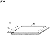
Figure 1 is an oblique view illustrating a secondary battery according to an embodiment of the present invention; -
Figure 2 is a sectional view of the secondary battery shown inFigure 1 ; -
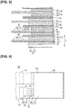
Figure 3 is a sectional view illustrating a battery body and power generation elements shown inFigure 2 ; -
Figure 4 is a plan view illustrating a negative electrode shown inFigure 3 ; -
Figure 5 is a plan view illustrating a positive electrode shown inFigure 3 ; -
Figure 6 is a sectional view illustrating slits shown inFigure 4 ; -
Figure 7 is a plan view illustrating a first modification of an embodiment of the present invention; -
Figure 8 is a plan view illustrating a second modification of an embodiment of the present invention; -
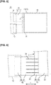
Figure 9 is a plan view illustrating a third modification of an embodiment of the present invention; -
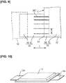
Figure 10 is an oblique view illustrating a fourth modification of an embodiment of the present invention; -
Figure 11 is a plan view illustrating the fourth modification of an embodiment of the present invention; -
Figure 12 is a plan view illustrating a fifth modification of an embodiment of the present invention; -
Figure 13 is a plan view illustrating a sixth modification of an embodiment of the present invention; and -
Figure 14 is a plan view illustrating a seventh modification of an embodiment of the present invention. - Embodiments of the present invention are described below with reference to the accompanying drawings. Ratios of dimensions in the drawings are sometimes exaggerated for convenience of description, and may vary from actual ratios.
-
Figure 1 is an oblique view illustrating a secondary battery according to an embodiment of the present invention, andFigure 2 is a sectional view of the secondary battery shown inFigure 1 . - A
secondary battery 10 according to an embodiment of the present invention is a non-bipolar lithium-ion secondary battery, and has anegative electrode tab 12, apositive electrode tab 14, and anexterior body 16, as indicated inFigure 1 . Thesecondary battery 10 is, for example, formed into an assembled battery and used as a power source device for a vehicle. The vehicle is, for example, an electric automobile or a hybrid electric automobile. - The
negative electrode tab 12 and thepositive electrode tab 14 are strong electrode terminals comprising highly electroconductive members. The tabs extend out from inside theexterior body 16, and are used in order to send out an electric current. Thenegative electrode tab 12 and thepositive electrode tab 14 are preferably covered, for example, by a heat-resistant and insulating heat-shrinkable tubing, and are thereby reliably prevented from coming in electrical contact with peripheral equipment, wiring, etc. - As indicated in
Figure 2 , abattery body 20 is disposed inside theexterior body 16, and theexterior body 16 is used to prevent shock of external origin or environmental degradation. Theexterior body 16 is formed by joining some or all of an external peripheral part of a sheet member. Examples of the joining method include thermal fusion bonding. - The
battery body 20 has a plurality of power generation elements (unit cells) 22. Thepower generation elements 22 are stacked and electrically connected in parallel. Reference symbol S is used to indicate a stacking direction of thepower generation elements 22. - The highly electroconductive members constituting the
negative electrode tab 12 and thepositive electrode tab 14 are, for example, aluminum, copper, titanium, nickel, stainless steel, or an alloy thereof. - The sheet member constituting the
exterior body 16 is preferably constituted from a polymer-metal composite laminate film, for the sake of weight reduction and thermal conductivity. Examples of the polymer include polypropylene, polyethylene, or another thermoplastic resin material. The metal is, for example, aluminum, stainless steel, nickel, copper, or another metal (including alloys of these). Theexterior body 16 is not limited to being constituted from a pair of laminate films (sheet members); for example, a laminate film formed in a bag shape in advance can be used as well. - The battery body and the power generation elements are described in more detail below.
-
Figure 3 is a sectional view illustrating the battery body and the power generation elements shown inFigure 2 . - As indicated in
Figure 3 , thebattery body 20 hasnegative electrodes 30,separators 50, andpositive electrodes 60. - The
negative electrodes 30 have acollector 32 and a substantially rectangular negative electrodeactive material layer 34. A negative electrodeactive material layer 34 is disposed on both surfaces of thecollector 32 in the stacking direction S. In other words, thecollector 32 is shared by adjacentnegative electrodes 30. - The
collector 32 is, for example, constituted from a copper foil having a thickness of about 1-100 µm. - The negative electrode active material layers 34 contain a negative electrode active material and additives, and have a thickness of about 1-100 µm, for example. The negative electrode active material has a composition whereby lithium ions can be desorbed during discharging and lithium ions can be occluded during charging. The additives are a binder and an electroconductivity auxiliary. The binder is added for the purpose of maintaining the structure of the negative electrode, and has a function for binding together constituent materials of the negative electrode active material layers 34, and a function for causing the negative electrode active material layers 34 to bind to the
collector 32. The binder is constituted from carboxymethylcellulose (CMC) and styrene-butadiene rubber (SBR), for example. The electroconductivity auxiliary is constituted from a carbon material, etc. having good electrical conductivity, and is blended in order to enhance the electroconductivity of the negative electrode active material layers 34. The carbon material is acetylene black, for example. - In the present embodiment, the negative electrode active material includes a silicon-based material. Silicon has a better lithium ion occluding ability per unit volume than graphite, etc., which makes it possible to increase the capacity of a secondary battery. In particular, in the present embodiment, wrinkling is suppressed, as described hereinafter, and a negative electrode active material containing silicon, which has high expansibility, can therefore easily be applied.
- The
positive electrodes 60 have acollector 62 and substantially rectangular positive electrode active material layers 64. The positive electrode active material layers 64 are disposed on both surfaces of thecollector 62 in the stacking direction S. In other words, thecollector 62 is shared by adjacentpositive electrodes 60. - The
collector 62 has a thickness of about 1-100 µm, for example. The material constituting thecollector 62 is the same as the material constituting thecollector 32 of thenegative electrode 30. - The positive electrode active material layers 64 contain a positive electrode active material and additives, and have a thickness of about 1-100 µm, for example. The positive electrode active material has a composition whereby lithium ions can be desorbed during charging and lithium ions can be occluded during discharging. The positive electrode active material is LiNiCoAlO2, for example. The additives are a binder and an electroconductivity auxiliary. The binder is added for a purpose of maintaining the structure of the positive electrode, and has a function for binding together constituent materials of the positive electrode active material layers 64, and a function for causing the positive electrode active material layers 64 to bind to the
collector 62. The binder is constituted from polyvinylidene fluoride (PVdF), for example. The electroconductivity auxiliary is blended in order to enhance the electroconductivity of the positive electrode active material layers 64, and is the same as the electroconductivity auxiliary in thenegative electrodes 30. - The
separators 50 are substantially rectangular porous material sheets (porous film) formed from polypropylene, and have a thickness of about 1-50 µm, for example. Theseparators 50 are disposed between the negative electrode active material layers 34 and the positive electrode active material layers 64, and the negative electrode active material layers 34 and the positive electrode active material layers 64 face each other, interposed by theseparators 50. - The
separators 50 are impregnated with an electrolyte, and constitute electrolyte layers for retaining the electrolyte. The electrolyte is a liquid electrolyte, for example. In other words, theseparators 50 have a function for ensuring conductivity of lithium ions (carrier ions) between thepositive electrodes 60 and thenegative electrodes 30, and function as barriers between thepositive electrodes 60 and thenegative electrodes 30. - Each of the
power generation elements 22 is constituted from acollector 32 on which a negative electrodeactive material layer 34 is disposed, the negative electrodeactive material layer 34, aseparator 50, a positive electrodeactive material layer 64, and acollector 62 on which the positive electrodeactive material layer 64 is disposed. Thecollectors 32 and thecollectors 62 are shared by adjacentpower generation elements 22. - The negative electrode
active material layer 34 is configured so as to have a larger area than the positive electrodeactive material layer 64. A decrease in a facing area between the negative electrodeactive material layer 34 and the positive electrodeactive material layer 64 is thereby suppressed even when the positive electrodeactive material layer 64 becomes misaligned with the negative electrodeactive material layer 34. Fluctuation in power generation capacity due to a decrease in the facing area is therefore prevented. - The collectors, the silicon-based material of the negative electrode active material, the negative electrode binder, the positive electrode active material, the positive electrode binder, the electroconductivity auxiliary, the separators, and the composition of the electrolyte, etc., will next be described in this order.
- The material constituting the
collectors 32 is not limited to copper, and another metal or an electroconductive resin is also applicable. The other metal is aluminum, nickel, iron, stainless steel, titanium, a cladding material of nickel and aluminum, a cladding material of copper aluminum, or a cladding material of a combination of these metals, for example. The electroconductive resin is an electroconductive polymer material, an electroconductive polymer material to which an electroconductive filler is added, or a non-electroconductive polymer material to which an electroconductive filler is added, for example. - The silicon-based material of the negative electrode active material is silicon metal (elemental Si), a silicon alloy, a silicon oxide, a silicon compound, or a silicon semiconductor, for example. The silicon alloy includes aluminum, tin, zinc, nickel, copper, titanium, vanadium, magnesium, lithium, or another metal alloyed with silicon. The silicon alloy is preferably a Si-Sn-Ti-based alloy or another alloy based on three or more elements. The silicon oxide is SiO2, SiO, SiOx, etc. The SiOx is a mixture of amorphous SiO2 particles and Si particles (where x represents a number of oxygen atoms satisfying a valence of Si). The silicon compound contains at least one component selected from the group consisting of lithium, carbon, aluminum, tin, zinc, nickel, copper, titanium, vanadium, and magnesium, for example. The negative electrode active material is not limited to a form including only one type of silicon-based material.
- The negative electrode binder is not limited to a form including styrene-butadiene rubber (SBR) and carboxymethylcellulose (CMC). For example, a rubber-based binder other than styrene-butadiene rubber (SBR) or a water-soluble polymer other than carboxymethylcellulose (CMC) is also applicable as the negative electrode binder. The negative electrode binder may be a single material, or three or more materials may be used jointly as needed.
- The positive electrode active material is not limited to a form including LiNiCoAlO2, and LiMn2O4, LiNiO2, LiCoO2, LiNiMnCoO2, LiFePO4, etc., for example, are also applicable as appropriate.
- The positive electrode binder is not limited to being constituted from polyvinylidene fluoride (PVdF).
- The electroconductivity auxiliary is not limited to being constituted from acetylene black. For example, a carbon powder other than acetylene black, vapor-grown carbon fibers (VGCF®) and other carbon fibers, expanded graphite, etc., are also applicable.
- The porous material sheet constituting the separators is not limited to being formed from polypropylene. For example, the porous material sheet can also be formed from polyethylene or another polyolefin other than polypropylene, a layered body in which a plurality of polyolefins are layered, polyimides, aramids, polyvinylidene fluoride-hexafluoropropylene (PVdF-HFP), glass fibers, etc. The separators can also be constituted from nonwoven fabric sheets. The nonwoven fabric sheets are formed from, for example, cotton, rayon, acetate, Nylon®, polyester, polyolefins such as polyethylene or polypropylene, polyimides, aramids, etc.
- The liquid electrolyte retained by the separators has a solvent and a lithium salt as a supporting electrolyte dissolved in the solvent. Examples of the lithium salt include Li(CF3SO2)2N, Li(C2F5SO2)2N, LiPF6, LiBF4, LiAsF6, LiTaF6, LiClO4, and LiCF3SO3. The solvent is ethylene carbonate (EC), propylene carbonate (PC), butylene carbonate (BC), vinylene carbonate (VC), dimethyl carbonate (DMC), diethyl carbonate (DEC), ethyl methyl carbonate (EMC), or methyl propyl carbonate (MPC), for example.
- The electrolyte retained by the separators is not limited to a liquid electrolyte. For example, the separators can also retain a gel polymer electrolyte. The gel polymer electrolyte is constituted from a matrix polymer (host polymer) infused with a liquid electrolyte. The matrix polymer is an ion-conductive polymer. Examples of the ion-conductive polymer include polyethylene oxide (PEO), polypropylene oxide (PPO), and copolymers thereof.
- A structure of the negative electrodes and the positive electrodes will next be described.
-
Figure 4 is a plan view illustrating a negative electrode shown inFigure 3 , andFigure 5 is a plan view illustrating a positive electrode shown inFigure 3 . - As indicated in
Figure 4 , thecollector 32 of thenegative electrode 30 has anactive material region 40, a non-active-material region 46, and slits 36. Theactive material region 40 is a region in which the negative electrodeactive material layer 34 is disposed, and has a facingsection 42 and anon-facing section 44. - The facing
section 42 is a region facing the positive electrodeactive material layer 64, interposed by theseparator 50. Thenon-facing section 44 is a region adjacent to the facingsection 42 and not facing the positive electrode active material layer 64 (seeFigure 3 ). - The non-active-
material region 46 has atransition section 47 and ajunction site 48, and protrudes from oneside 41 of the substantially rectangularactive material region 40. Thejunction site 48 is a part that is joined (fixed) to thenegative electrode tab 12 for drawing electric current toward the outside (seeFigure 2 ). Thetransition section 47 is positioned between thejunction site 48 and theactive material region 40. In other words, thejunction site 48 faces theactive material region 40, interposed by thetransition section 47. The reference symbol C is used to indicate a center section of the oneside 41. - As indicated in
Figure 5 , thecollector 62 of thepositive electrode 60 has anactive material region 70 and a non-active-material region 76. Theactive material region 70 is a region in which the positive electrodeactive material layer 64 is disposed, and is a facingsection 72 facing the negative electrodeactive material layer 34, interposed by the separator 50 (seeFigure 3 ). - The non-active-
material region 76 has atransition section 77 and ajunction site 78, and protrudes from one side 71 of the substantially rectangularactive material region 70. Thejunction site 78 is a part that is joined (fixed) to thepositive electrode tab 14 for drawing electric current toward the outside (seeFigure 2 ). Thetransition section 77 is positioned between thejunction site 78 and theactive material region 70. In other words, thejunction site 78 faces theactive material region 70, interposed by thetransition section 77. - The non-active-
material region 76 is positioned so as not to overlap the non-active-material region 46 of thecollector 32 of thenegative electrode 30 in the stacking direction S. Ultrasonic welding or resistance welding, for example, is applied to join thejunction site 48 and thenegative electrode tab 12 and to join thejunction site 78 and thepositive electrode tab 14. - The
slits 36 will next be described in detail. -
Figure 6 is an enlarged view illustrating the slits shown inFigure 4 . - As indicated in
Figure 6 , thenegative electrode collector 32 has a plurality ofslits 36. Theslits 36 are juxtaposed in a direction (intersecting direction) I intersecting with the oneside 41 of theactive material region 40, and extend from the non-active-material region 46 to a boundary of the facingsection 42 and thenon-facing section 44. - For example, in the case of a power generation element (secondary battery) formed by stacking 15 positive electrodes 60 (having an
active material region 70 200 × 190 mm in size) and 16 negative electrodes 30 (having anactive material region 40 205 × 195 mm in size), interposed by a separator (having a size of 219 x191 mm, a thickness of 25 µm, and a porosity of 55%), five slits are disposed. A length of the slits in the non-active-material region 46 is 8.5 mm, and the length of the slits in theactive material region 40 is 1.5 mm, and a total length of the slits is therefore 10 mm. A slit width is 0.5 mm. A slit interval is 10 mm. - The
slits 36 extend from the non-active-material region 46 to theactive material region 40, and can therefore reliably relieve stress that occurs in thenegative electrode 30 due to a dimensional difference in expansion and contraction between the non-active-material region 46 and theactive material region 40 during charging and discharging of thesecondary battery 10. Wrinkling originating at a boundary of the non-active-material region 46 and theactive material region 40 is therefore suppressed even when there is a large change in volume of the silicon included in the negative electrodeactive material layer 34. From the perspective of suppressing an effect (interference) on electrical conductivity and strength of thecollector 32, the slit width is preferably as small as possible. A method of forming theslits 36 is not particularly limited, and theslits 36 can be formed by press working or machining, for example. - The
slits 36 are set apart from thejunction site 48 to which thenegative electrode tab 12 is fixed, and extend from a point partway along thetransition section 47 in the non-active-material region 46. Consequently, the effect (interference) of the slits on the electrical conductivity and junction strength between thenegative electrode tab 12 and thejunction site 48 can be suppressed. Theslits 36 extend from thetransition section 47 positioned between thejunction site 48 and theactive material region 40, and stress caused by fixing of thejunction site 48 to thenegative electrode tab 12 can therefore be efficiently relieved. - The First to Seventh Modifications will next be described in order.
-
Figure 7 is a plan view illustrating a first modification of an embodiment of the present invention. - The
negative electrode 30 is not limited to havingslits 36 extending from the non-active-material region 46 to the boundary of the facingsection 42 and thenon-facing section 44. For example, as in the first modification inFigure 7 , thenegative electrode 30 can also haveslits 36A configured so as to extend to a predetermined position set apart from the boundary of the facingsection 42 and thenon-facing section 44. -
Figure 8 is a plan view illustrating the second modification of an embodiment of the present invention. - The present invention is not limited to a form in which the slits are the same size. For example, a slit length L can also be increased progressively toward the center section C of the one
side 41 of theactive material region 40, as in the case of theslits 36B of the second modification inFigure 8 . -
Figure 9 is a plan view illustrating the third modification of an embodiment of the present invention. - The present invention is not limited to a form in which intervals between the slits are the same. For example, a slit interval D can also be decreased progressively toward the center section C of the one
side 41 of theactive material region 40, as in the case of theslits 36C of the third modification inFigure 9 . -
Figures 10 and11 are an oblique view and a plan view, respectively, illustrating the fourth modification of an embodiment of the present invention. - The
secondary battery 10 is not limited to having thenegative electrode tab 12 and thepositive electrode tab 14 extending outward from one side of theexterior body 16. For example, thesecondary battery 10 can also be configured so as to have anegative electrode tab 12A and apositive electrode tab 14A extending outward from one side of theexterior body 16 and one side positioned on an opposite side from the one side, as in the fourth modification inFigure 10 . - In this case, a
negative electrode 30A hasslits 36D extending from a non-active-material region 46A to a boundary of a facingsection 42A and anon-facing section 44A, as indicated inFigure 11 . Thereference symbols -
Figures 12 through 14 are plan views illustrating the fifth to seventh modifications, respectively, of an embodiment of the present invention. - The slits in the
negative electrode 30A can be modified in the same manner as in the first to third modifications. - For example, as in the fifth modification in
Figure 7 , thenegative electrode 30A can also haveslits 36E configured so as to extend to a predetermined position in thenon-facing section 44A that is set apart from the boundary of the facingsection 42A and thenon-facing section 44A. A slit length L can also be increased progressively toward the center section C of the oneside 41 of theactive material region 40A, as in the case of theslits 36F of the sixth modification inFigure 13 . A slit interval D can also be decreased progressively toward the center section C of the oneside 41 of theactive material region 40A, as in the case of theslits 36G of the seventh modification inFigure 14 . - In the present embodiment, the slits extending from the non-active-material region to the active material region relieve stress that occurs in the negative electrode during charging and discharging of the secondary battery, as described above. Wrinkling originating at the boundary of the non-active-material region and the active material region is therefore suppressed even when there is a large change in volume of the silicon. Consequently, a secondary battery can be provided in which it is possible to suppress wrinkling which originates at the boundary of the non-active-material region and the active material region in the negative electrode.
- The slits preferably extend to the boundary of the facing section, which faces the active material region of the positive electrode collector, interposed by the electrolyte layer, and the non-facing section, which does not face the active material region. In this case, stress occurring in the negative electrode during charging and discharging of the secondary battery can be more reliably relieved.
- The slits are preferably set apart from the junction site of the tab for drawing electric current toward the outside. In this case, the effect (interference) of the slits on electrical conductivity and junction strength between the tab and the junction site can be suppressed.
- The slits preferably extend from the transition section positioned between the junction site and the active material region. In this case, stress caused by fixing of the junction site to the tab can be efficiently relieved.
- When a plurality of slits are provided, stress occurring in the negative electrode during charging and discharging of the secondary battery can be more reliably relieved.
- Stress increases closer to the center section of the one side of the active material region, and the stress can therefore be more reliably relieved by increasing the slit length or decreasing the slit interval (increasing an arrangement density of the slits) progressively toward the center section of the one side of the active material region.
- The area of each negative electrode active material layer is preferably greater than the area of each positive electrode active material layer. In this case, when the positive electrode active material layers become misaligned with the negative electrode active material layers with respect to a transverse direction intersecting with the stacking direction, an effect of the misalignment on a facing area can be suppressed, and fluctuation in power generation capacity can be prevented.
- The present invention is not limited to the embodiment described above, and various modifications thereof are possible within the scope of the claims. For example, the secondary battery can also be used in the form of a serialized and/or parallelized assembled battery. The first to third modifications can also be combined, as appropriate, and the fourth to seventh modifications can be combined, as appropriate.
-
- 10:
- secondary battery
- 12, 12A:
- negative electrode tab
- 14, 14A:
- positive electrode tab
- 16:
- exterior body
- 20:
- battery body
- 22
- power generation element
- 30, 30A:
- negative electrode
- 32, 32A:
- collector (negative electrode collector)
- 34:
- negative electrode active material layer
- 36, 36A-36F:
- slits
- 40, 40A:
- active material region
- 41: one
- side
- 42, 42A:
- facing section
- 44, 44A:
- non-facing section
- 46, 46A:
- non-active-material region
- 47, 47A:
- transition section
- 48, 48A:
- junction site
- 50:
- separator (electrolyte layer)
- 60, 60A:
- positive electrode
- 62:
- collector (positive electrode collector)
- 64:
- positive electrode active material layer
- 70:
- active material region
- 71:
- one side
- 72:
- facing section
- 76:
- non-active-material region
- 77:
- transition section
- 78:
- junction section
- 80:
- collector
- C:
- center section
- D:
- slit interval
- I:
- intersecting direction
- L:
- slit length
- S:
- stacking direction
Claims (8)
- A secondary battery comprising:a power generation element including: a positive electrode having a positive electrode collector on which a positive electrode active material layer is disposed; an electrolyte layer for retaining an electrolyte; and a negative electrode having a negative electrode collector on which is disposed a negative electrode active material layer having a negative electrode active material containing silicon;the positive electrode active material layer and the negative electrode active material layer facing each other with the electrolyte layer interposed therebetween; andthe negative electrode collector havingan active material region in which the negative electrode active material layer is disposed,a non-active-material region in which the negative electrode active material layer is not disposed, anda slit extending from the non-active-material region to the active material region.
- The secondary battery according to claim 1, wherein
the positive electrode collector has an active material region in which the positive electrode active material layer is disposed,
the active material region of the negative electrode collector having a facing section facing the active material region of the positive electrode collector with the electrolyte layer interposed therebetween, and a non-facing section not facing the active material region of the positive electrode collector, and
the slit extends to a boundary of the facing section and the non-facing section. - The secondary battery according to claim 1 or 2, wherein
the non-active-material region of the negative electrode collector has a junction site to which a tab for drawing electric current to an outside is joined, and the slit is spaced apart from the junction site. - The secondary battery according to claim 3, wherein
the non-active-material region of the negative electrode collector has a transition section positioned between the junction site and the active material region of the negative electrode collector, and
the slit extends from the transition section. - The secondary battery according to any one of claims 1 through 4, wherein
the negative electrode collector has a plurality of the slits,
the active material region of the negative electrode collector is substantially rectangular, and
the slits are juxtaposed in a direction intersecting with one side of the active material region of the negative electrode collector. - The secondary battery according to claim 5, wherein a length of the slits increases progressively toward a center section of the one side.
- The secondary battery according to claim 5 or 6, wherein an interval of the slits decreases progressively toward the center section of the one side.
- The secondary battery according to any one of claims 1 through 7, wherein an area of the negative electrode active material layer is greater than an area of the positive electrode active material layer.
Applications Claiming Priority (1)
| Application Number | Priority Date | Filing Date | Title |
|---|---|---|---|
| PCT/JP2017/009063 WO2018163294A1 (en) | 2017-03-07 | 2017-03-07 | Secondary battery |
Publications (3)
| Publication Number | Publication Date |
|---|---|
| EP3595075A1 true EP3595075A1 (en) | 2020-01-15 |
| EP3595075A4 EP3595075A4 (en) | 2020-03-18 |
| EP3595075B1 EP3595075B1 (en) | 2023-11-01 |
Family
ID=63447442
Family Applications (1)
| Application Number | Title | Priority Date | Filing Date |
|---|---|---|---|
| EP17899847.2A Active EP3595075B1 (en) | 2017-03-07 | 2017-03-07 | Secondary battery |
Country Status (6)
| Country | Link |
|---|---|
| US (1) | US20210288351A1 (en) |
| EP (1) | EP3595075B1 (en) |
| JP (1) | JPWO2018163294A1 (en) |
| KR (1) | KR20190100387A (en) |
| CN (1) | CN110392954A (en) |
| WO (1) | WO2018163294A1 (en) |
Families Citing this family (2)
| Publication number | Priority date | Publication date | Assignee | Title |
|---|---|---|---|---|
| JP7091933B2 (en) * | 2018-08-22 | 2022-06-28 | トヨタ自動車株式会社 | Manufacturing method of stacked batteries |
| JP7327292B2 (en) * | 2020-06-19 | 2023-08-16 | トヨタ自動車株式会社 | assembled battery |
Family Cites Families (11)
| Publication number | Priority date | Publication date | Assignee | Title |
|---|---|---|---|---|
| AU7951100A (en) | 1999-10-22 | 2001-04-30 | Sanyo Electric Co., Ltd. | Electrode for lithium secondary cell and lithium secondary cell |
| JP4462245B2 (en) * | 2006-07-19 | 2010-05-12 | トヨタ自動車株式会社 | Secondary battery, laminated secondary battery and assembled battery |
| JP5454032B2 (en) * | 2009-09-14 | 2014-03-26 | 日産自動車株式会社 | Thin battery |
| DE112011100008T5 (en) * | 2010-04-06 | 2012-06-28 | Nec Tokin Corp. | Electric storage device |
| WO2012169282A1 (en) * | 2011-06-10 | 2012-12-13 | 日本電気株式会社 | Lithium ion secondary battery |
| JP2013157283A (en) * | 2012-01-31 | 2013-08-15 | Nissan Motor Co Ltd | Electrode of secondary battery |
| WO2014050988A1 (en) * | 2012-09-27 | 2014-04-03 | Necエナジーデバイス株式会社 | Lithium ion secondary battery and method for manufacturing same |
| JP6162431B2 (en) * | 2013-02-28 | 2017-07-12 | 株式会社東芝 | battery |
| JP5999442B2 (en) * | 2013-04-16 | 2016-09-28 | トヨタ自動車株式会社 | Nonaqueous electrolyte secondary battery |
| JP6655865B2 (en) * | 2014-05-22 | 2020-03-04 | 株式会社Gsユアサ | Storage element |
| KR20170010587A (en) * | 2015-07-20 | 2017-02-01 | 삼성전자주식회사 | Electrode plate, Electrode Assembly and Secondary battery comprising electrode plate |
-
2017
- 2017-03-07 JP JP2019504178A patent/JPWO2018163294A1/en not_active Ceased
- 2017-03-07 US US16/483,638 patent/US20210288351A1/en not_active Abandoned
- 2017-03-07 CN CN201780088140.0A patent/CN110392954A/en not_active Withdrawn
- 2017-03-07 EP EP17899847.2A patent/EP3595075B1/en active Active
- 2017-03-07 WO PCT/JP2017/009063 patent/WO2018163294A1/en unknown
- 2017-03-07 KR KR1020197022940A patent/KR20190100387A/en not_active Application Discontinuation
Also Published As
| Publication number | Publication date |
|---|---|
| CN110392954A (en) | 2019-10-29 |
| KR20190100387A (en) | 2019-08-28 |
| WO2018163294A1 (en) | 2018-09-13 |
| JPWO2018163294A1 (en) | 2019-12-12 |
| EP3595075B1 (en) | 2023-11-01 |
| US20210288351A1 (en) | 2021-09-16 |
| EP3595075A4 (en) | 2020-03-18 |
Similar Documents
| Publication | Publication Date | Title |
|---|---|---|
| KR101061705B1 (en) | Batteries, pack batteries using them, and vehicles equipped with these batteries | |
| JP5699559B2 (en) | Non-aqueous electrolyte battery | |
| US10177387B2 (en) | Bipolar battery current collector that contracts to interrupt a flow of electric current in a direction thereof and bipolar battery | |
| US20210110979A1 (en) | Ultra-high power hybrid cell design with uniform thermal distribution | |
| US20130177787A1 (en) | Current collector and nonaqueous secondary battery | |
| US11764448B2 (en) | Secondary battery | |
| KR20050035108A (en) | Flat cell, battery, combined battery, and vehicle | |
| US10818901B2 (en) | Laminated cell and method for manufacturing same | |
| JP2018530110A (en) | Cable type secondary battery and manufacturing method thereof | |
| JP3687632B2 (en) | Thin battery | |
| JP2012151036A (en) | Laminated battery | |
| EP3595073A1 (en) | Secondary battery and method for manufacturing secondary battery | |
| JP5631537B2 (en) | Bipolar secondary battery | |
| EP3595075B1 (en) | Secondary battery | |
| KR101880842B1 (en) | Battery and battery manufacturing method | |
| JP7238971B2 (en) | Secondary battery and manufacturing method thereof | |
| JP6048477B2 (en) | Method for producing non-aqueous electrolyte battery | |
| KR20210035591A (en) | Electrode assembly and secondary battery including the same | |
| JP3702868B2 (en) | Thin battery | |
| JP6928738B2 (en) | Lithium ion battery | |
| JP2005149783A (en) | Secondary battery, battery pack, complex battery pack, and vehicle | |
| JP2021099949A (en) | All-solid battery | |
| JP2018147602A (en) | Secondary battery | |
| JP7115554B2 (en) | secondary battery | |
| KR20230128469A (en) | Electrodes, electrode assemblies and secondary batteries |
Legal Events
| Date | Code | Title | Description |
|---|---|---|---|
| STAA | Information on the status of an ep patent application or granted ep patent |
Free format text: STATUS: THE INTERNATIONAL PUBLICATION HAS BEEN MADE |
|
| PUAI | Public reference made under article 153(3) epc to a published international application that has entered the european phase |
Free format text: ORIGINAL CODE: 0009012 |
|
| STAA | Information on the status of an ep patent application or granted ep patent |
Free format text: STATUS: REQUEST FOR EXAMINATION WAS MADE |
|
| 17P | Request for examination filed |
Effective date: 20191004 |
|
| AK | Designated contracting states |
Kind code of ref document: A1 Designated state(s): AL AT BE BG CH CY CZ DE DK EE ES FI FR GB GR HR HU IE IS IT LI LT LU LV MC MK MT NL NO PL PT RO RS SE SI SK SM TR |
|
| AX | Request for extension of the european patent |
Extension state: BA ME |
|
| A4 | Supplementary search report drawn up and despatched |
Effective date: 20200219 |
|
| RIC1 | Information provided on ipc code assigned before grant |
Ipc: H01M 4/70 20060101ALI20200213BHEP Ipc: H01M 10/04 20060101ALI20200213BHEP Ipc: H01M 10/0585 20100101AFI20200213BHEP |
|
| DAV | Request for validation of the european patent (deleted) | ||
| DAX | Request for extension of the european patent (deleted) | ||
| RAP3 | Party data changed (applicant data changed or rights of an application transferred) |
Owner name: RENAULT S.A.S Owner name: ENVISION AESC JAPAN LTD. |
|
| RAP3 | Party data changed (applicant data changed or rights of an application transferred) |
Owner name: RENAULT S.A.S Owner name: ENVISION AESC JAPAN LTD. |
|
| GRAP | Despatch of communication of intention to grant a patent |
Free format text: ORIGINAL CODE: EPIDOSNIGR1 |
|
| STAA | Information on the status of an ep patent application or granted ep patent |
Free format text: STATUS: GRANT OF PATENT IS INTENDED |
|
| INTG | Intention to grant announced |
Effective date: 20230519 |
|
| P01 | Opt-out of the competence of the unified patent court (upc) registered |
Effective date: 20230608 |
|
| GRAS | Grant fee paid |
Free format text: ORIGINAL CODE: EPIDOSNIGR3 |
|
| GRAA | (expected) grant |
Free format text: ORIGINAL CODE: 0009210 |
|
| STAA | Information on the status of an ep patent application or granted ep patent |
Free format text: STATUS: THE PATENT HAS BEEN GRANTED |
|
| GRAF | Information related to payment of grant fee modified |
Free format text: ORIGINAL CODE: EPIDOSCIGR3 |
|
| AK | Designated contracting states |
Kind code of ref document: B1 Designated state(s): AL AT BE BG CH CY CZ DE DK EE ES FI FR GB GR HR HU IE IS IT LI LT LU LV MC MK MT NL NO PL PT RO RS SE SI SK SM TR |
|
| REG | Reference to a national code |
Ref country code: GB Ref legal event code: FG4D |
|
| REG | Reference to a national code |
Ref country code: CH Ref legal event code: EP |
|
| REG | Reference to a national code |
Ref country code: IE Ref legal event code: FG4D |
|
| REG | Reference to a national code |
Ref country code: DE Ref legal event code: R096 Ref document number: 602017076167 Country of ref document: DE |
|
| REG | Reference to a national code |
Ref country code: LT Ref legal event code: MG9D |
|
| REG | Reference to a national code |
Ref country code: NL Ref legal event code: MP Effective date: 20231101 |
|
| PG25 | Lapsed in a contracting state [announced via postgrant information from national office to epo] |
Ref country code: GR Free format text: LAPSE BECAUSE OF FAILURE TO SUBMIT A TRANSLATION OF THE DESCRIPTION OR TO PAY THE FEE WITHIN THE PRESCRIBED TIME-LIMIT Effective date: 20240202 |
|
| PG25 | Lapsed in a contracting state [announced via postgrant information from national office to epo] |
Ref country code: IS Free format text: LAPSE BECAUSE OF FAILURE TO SUBMIT A TRANSLATION OF THE DESCRIPTION OR TO PAY THE FEE WITHIN THE PRESCRIBED TIME-LIMIT Effective date: 20240301 |
|
| RAP2 | Party data changed (patent owner data changed or rights of a patent transferred) |
Owner name: AMPERE SAS Owner name: ENVISION AESC JAPAN LTD. |
|
| PG25 | Lapsed in a contracting state [announced via postgrant information from national office to epo] |
Ref country code: LT Free format text: LAPSE BECAUSE OF FAILURE TO SUBMIT A TRANSLATION OF THE DESCRIPTION OR TO PAY THE FEE WITHIN THE PRESCRIBED TIME-LIMIT Effective date: 20231101 |
|
| REG | Reference to a national code |
Ref country code: AT Ref legal event code: MK05 Ref document number: 1628274 Country of ref document: AT Kind code of ref document: T Effective date: 20231101 |
|
| PG25 | Lapsed in a contracting state [announced via postgrant information from national office to epo] |
Ref country code: NL Free format text: LAPSE BECAUSE OF FAILURE TO SUBMIT A TRANSLATION OF THE DESCRIPTION OR TO PAY THE FEE WITHIN THE PRESCRIBED TIME-LIMIT Effective date: 20231101 |
|
| RAP4 | Party data changed (patent owner data changed or rights of a patent transferred) |
Owner name: AMPERE SAS Owner name: AESC JAPAN LTD. |
|
| REG | Reference to a national code |
Ref country code: DE Ref legal event code: R081 Ref document number: 602017076167 Country of ref document: DE Owner name: RENAULT S.A.S., FR Free format text: FORMER OWNERS: ENVISION AESC JAPAN LTD., ZAMA-SHI, KANAGAWA, JP; RENAULT S.A.S., BOULOGNE-BILLANCOURT, FR Ref country code: DE Ref legal event code: R081 Ref document number: 602017076167 Country of ref document: DE Owner name: AESC JAPAN LTD., YOKOHAMA-SHI, JP Free format text: FORMER OWNERS: ENVISION AESC JAPAN LTD., ZAMA-SHI, KANAGAWA, JP; RENAULT S.A.S., BOULOGNE-BILLANCOURT, FR |
|
| PG25 | Lapsed in a contracting state [announced via postgrant information from national office to epo] |
Ref country code: AT Free format text: LAPSE BECAUSE OF FAILURE TO SUBMIT A TRANSLATION OF THE DESCRIPTION OR TO PAY THE FEE WITHIN THE PRESCRIBED TIME-LIMIT Effective date: 20231101 |
|
| PG25 | Lapsed in a contracting state [announced via postgrant information from national office to epo] |
Ref country code: ES Free format text: LAPSE BECAUSE OF FAILURE TO SUBMIT A TRANSLATION OF THE DESCRIPTION OR TO PAY THE FEE WITHIN THE PRESCRIBED TIME-LIMIT Effective date: 20231101 |
|
| PG25 | Lapsed in a contracting state [announced via postgrant information from national office to epo] |
Ref country code: NL Free format text: LAPSE BECAUSE OF FAILURE TO SUBMIT A TRANSLATION OF THE DESCRIPTION OR TO PAY THE FEE WITHIN THE PRESCRIBED TIME-LIMIT Effective date: 20231101 Ref country code: LT Free format text: LAPSE BECAUSE OF FAILURE TO SUBMIT A TRANSLATION OF THE DESCRIPTION OR TO PAY THE FEE WITHIN THE PRESCRIBED TIME-LIMIT Effective date: 20231101 Ref country code: IS Free format text: LAPSE BECAUSE OF FAILURE TO SUBMIT A TRANSLATION OF THE DESCRIPTION OR TO PAY THE FEE WITHIN THE PRESCRIBED TIME-LIMIT Effective date: 20240301 Ref country code: GR Free format text: LAPSE BECAUSE OF FAILURE TO SUBMIT A TRANSLATION OF THE DESCRIPTION OR TO PAY THE FEE WITHIN THE PRESCRIBED TIME-LIMIT Effective date: 20240202 Ref country code: ES Free format text: LAPSE BECAUSE OF FAILURE TO SUBMIT A TRANSLATION OF THE DESCRIPTION OR TO PAY THE FEE WITHIN THE PRESCRIBED TIME-LIMIT Effective date: 20231101 Ref country code: BG Free format text: LAPSE BECAUSE OF FAILURE TO SUBMIT A TRANSLATION OF THE DESCRIPTION OR TO PAY THE FEE WITHIN THE PRESCRIBED TIME-LIMIT Effective date: 20240201 Ref country code: AT Free format text: LAPSE BECAUSE OF FAILURE TO SUBMIT A TRANSLATION OF THE DESCRIPTION OR TO PAY THE FEE WITHIN THE PRESCRIBED TIME-LIMIT Effective date: 20231101 Ref country code: PT Free format text: LAPSE BECAUSE OF FAILURE TO SUBMIT A TRANSLATION OF THE DESCRIPTION OR TO PAY THE FEE WITHIN THE PRESCRIBED TIME-LIMIT Effective date: 20240301 |
|
| PGFP | Annual fee paid to national office [announced via postgrant information from national office to epo] |
Ref country code: DE Payment date: 20240320 Year of fee payment: 8 Ref country code: GB Payment date: 20240320 Year of fee payment: 8 |
|
| REG | Reference to a national code |
Ref country code: DE Ref legal event code: R081 Ref document number: 602017076167 Country of ref document: DE Owner name: RENAULT S.A.S., FR Free format text: FORMER OWNERS: AESC JAPAN LTD., YOKOHAMA-SHI, KANAGAWA, JP; RENAULT S.A.S., BOULOGNE-BILLANCOURT, FR |