EP3595061A1 - Positive electrode active material for potassium secondary battery and potassium secondary battery containing same - Google Patents
Positive electrode active material for potassium secondary battery and potassium secondary battery containing same Download PDFInfo
- Publication number
- EP3595061A1 EP3595061A1 EP18763829.1A EP18763829A EP3595061A1 EP 3595061 A1 EP3595061 A1 EP 3595061A1 EP 18763829 A EP18763829 A EP 18763829A EP 3595061 A1 EP3595061 A1 EP 3595061A1
- Authority
- EP
- European Patent Office
- Prior art keywords
- positive electrode
- electrode active
- active material
- secondary battery
- composition
- Prior art date
- Legal status (The legal status is an assumption and is not a legal conclusion. Google has not performed a legal analysis and makes no representation as to the accuracy of the status listed.)
- Granted
Links
Images


Classifications
-
- H—ELECTRICITY
- H01—ELECTRIC ELEMENTS
- H01M—PROCESSES OR MEANS, e.g. BATTERIES, FOR THE DIRECT CONVERSION OF CHEMICAL ENERGY INTO ELECTRICAL ENERGY
- H01M4/00—Electrodes
- H01M4/02—Electrodes composed of, or comprising, active material
- H01M4/36—Selection of substances as active materials, active masses, active liquids
- H01M4/58—Selection of substances as active materials, active masses, active liquids of inorganic compounds other than oxides or hydroxides, e.g. sulfides, selenides, tellurides, halogenides or LiCoFy; of polyanionic structures, e.g. phosphates, silicates or borates
- H01M4/5825—Oxygenated metallic salts or polyanionic structures, e.g. borates, phosphates, silicates, olivines
-
- C—CHEMISTRY; METALLURGY
- C01—INORGANIC CHEMISTRY
- C01B—NON-METALLIC ELEMENTS; COMPOUNDS THEREOF; METALLOIDS OR COMPOUNDS THEREOF NOT COVERED BY SUBCLASS C01C
- C01B25/00—Phosphorus; Compounds thereof
- C01B25/16—Oxyacids of phosphorus; Salts thereof
- C01B25/26—Phosphates
- C01B25/38—Condensed phosphates
- C01B25/42—Pyrophosphates
-
- H—ELECTRICITY
- H01—ELECTRIC ELEMENTS
- H01M—PROCESSES OR MEANS, e.g. BATTERIES, FOR THE DIRECT CONVERSION OF CHEMICAL ENERGY INTO ELECTRICAL ENERGY
- H01M10/00—Secondary cells; Manufacture thereof
- H01M10/05—Accumulators with non-aqueous electrolyte
- H01M10/054—Accumulators with insertion or intercalation of metals other than lithium, e.g. with magnesium or aluminium
-
- H—ELECTRICITY
- H01—ELECTRIC ELEMENTS
- H01M—PROCESSES OR MEANS, e.g. BATTERIES, FOR THE DIRECT CONVERSION OF CHEMICAL ENERGY INTO ELECTRICAL ENERGY
- H01M4/00—Electrodes
- H01M4/02—Electrodes composed of, or comprising, active material
- H01M4/13—Electrodes for accumulators with non-aqueous electrolyte, e.g. for lithium-accumulators; Processes of manufacture thereof
- H01M4/134—Electrodes based on metals, Si or alloys
-
- H—ELECTRICITY
- H01—ELECTRIC ELEMENTS
- H01M—PROCESSES OR MEANS, e.g. BATTERIES, FOR THE DIRECT CONVERSION OF CHEMICAL ENERGY INTO ELECTRICAL ENERGY
- H01M4/00—Electrodes
- H01M4/02—Electrodes composed of, or comprising, active material
- H01M4/13—Electrodes for accumulators with non-aqueous electrolyte, e.g. for lithium-accumulators; Processes of manufacture thereof
- H01M4/139—Processes of manufacture
- H01M4/1397—Processes of manufacture of electrodes based on inorganic compounds other than oxides or hydroxides, e.g. sulfides, selenides, tellurides, halogenides or LiCoFy
-
- C—CHEMISTRY; METALLURGY
- C01—INORGANIC CHEMISTRY
- C01P—INDEXING SCHEME RELATING TO STRUCTURAL AND PHYSICAL ASPECTS OF SOLID INORGANIC COMPOUNDS
- C01P2002/00—Crystal-structural characteristics
- C01P2002/70—Crystal-structural characteristics defined by measured X-ray, neutron or electron diffraction data
- C01P2002/74—Crystal-structural characteristics defined by measured X-ray, neutron or electron diffraction data by peak-intensities or a ratio thereof only
-
- H—ELECTRICITY
- H01—ELECTRIC ELEMENTS
- H01M—PROCESSES OR MEANS, e.g. BATTERIES, FOR THE DIRECT CONVERSION OF CHEMICAL ENERGY INTO ELECTRICAL ENERGY
- H01M4/00—Electrodes
- H01M4/02—Electrodes composed of, or comprising, active material
- H01M2004/026—Electrodes composed of, or comprising, active material characterised by the polarity
- H01M2004/028—Positive electrodes
-
- Y—GENERAL TAGGING OF NEW TECHNOLOGICAL DEVELOPMENTS; GENERAL TAGGING OF CROSS-SECTIONAL TECHNOLOGIES SPANNING OVER SEVERAL SECTIONS OF THE IPC; TECHNICAL SUBJECTS COVERED BY FORMER USPC CROSS-REFERENCE ART COLLECTIONS [XRACs] AND DIGESTS
- Y02—TECHNOLOGIES OR APPLICATIONS FOR MITIGATION OR ADAPTATION AGAINST CLIMATE CHANGE
- Y02E—REDUCTION OF GREENHOUSE GAS [GHG] EMISSIONS, RELATED TO ENERGY GENERATION, TRANSMISSION OR DISTRIBUTION
- Y02E60/00—Enabling technologies; Technologies with a potential or indirect contribution to GHG emissions mitigation
- Y02E60/10—Energy storage using batteries
Definitions
- the present invention relates to a positive electrode active material for a potassium secondary battery and a potassium secondary battery including the same.
- the secondary batteries which have received the most attention until now, are lithium secondary batteries, and the lithium secondary batteries are not only rapidly and increasingly used for power supply of portable electronic devices and electric vehicles by allowing electric energy to be charged and discharged over a long period of time at a high density, but also widely used for energy storage systems (ESSs) configured to store electric power produced in a power plant and efficiently manage electric energy produced by methods such as solar energy and wind energy.
- ESSs energy storage systems
- lithium used in the lithium secondary batteries is a limited resource localized in specific areas, there is a problem that it is not only expensive but also difficult to cope with growing demands for batteries and energy storage devices.
- non-lithium batteries which do not use lithium as a main raw material
- the non-lithium batteries use alkali metals, alkaline earth metals, Group 3A metals, transition metals, and the like except for lithium.
- metal oxides having a layered structure in the form of O3, P2 and P3, Prussian blue having an open framework structure, phosphates, fluorophosphates, pyrophosphates, sulfides, and the like have been developed as positive electrode active materials for sodium-ion batteries, but materials that meet a sufficient level of capacity, lifespan, and the like are still rare.
- Potassium is similar in potential to lithium, and mobility of potassium ions is excellent, and thus a potential for secondary batteries is considerable, but little attention has been received until now. Accordingly, studies on a Prussian blue-like material (KFe III Fe II (CN) 6 ) disclosed in the following patent document have been mainly and actively conducted as a positive electrode active material for a potassium secondary battery, and it has been known that materials such as K x TiS 2 , K x CoO 2 , K x MnO 2 , and the like may also be used as the positive electrode active material, but as compared with lithium secondary batteries or the sodium secondary batteries, positive electrode active materials for potassium secondary batteries have been rarely studied.
- KFe III Fe II (CN) 6 Prussian blue-like material
- the present invention is directed to providing a material which may be used as a positive electrode active material for a potassium secondary battery and a potassium secondary battery including the material.
- One aspect of the present invention provides a positive electrode active material for a potassium secondary battery, which is a crystalline material including K, transition metals, P, and O, and the material includes, as a main phase, a phase showing a diffraction peak having a relative intensity of 5% or more in a range of Bragg angles (2 ⁇ ) of an X-ray diffraction pattern of 14.7° to 15.7°, 22.1° to 23.1°, 25.5° to 26.5°, and 29.7° to 30.8°, when a relative intensity of a diffraction peak having the strongest intensity is taken as 100% in the powder X-ray diffraction pattern of the material.
- a potassium secondary battery including a positive electrode, a negative electrode, and an electrolyte
- the positive electrode includes a positive electrode active material including K, transition metals, P, and O
- the material includes, as a main phase, a phase showing a diffraction peak having a relative intensity of 5% or more in a range of Bragg angles (2 ⁇ ) of an X-ray diffraction pattern of 14.7° to 15.7°, 22.1° to 23.1°, 25.5° to 26.5°, and 29.7° to 30.8°, when a relative intensity of a diffraction peak having the strongest intensity is taken as 100% in the powder X-ray diffraction pattern.
- potassium ions are easily reversibly intercalated/de-intercalated, have excellent structural stability and are excellent in charge and discharge cycle characteristics, and thus it is expected to be suitably used, especially, for an energy storage system (ESS).
- ESS energy storage system
- a positive electrode active material for a potassium secondary battery can use a non-aqueous electrolyte.
- a potassium secondary battery including the positive electrode active material for a potassium secondary battery.
- a positive electrode active material for a potassium secondary battery according to the present invention includes K, transition metals, P, and O, and may be a material including, as a main phase, a phase showing a diffraction peak having a relative intensity of 5% or more in a range of Bragg angles (2 ⁇ ) of an X-ray diffraction pattern of 14.7° to 15.7°, 22.1° to 23.1°, 25.5° to 26.5°, and 29.7° to 30.8°, when a relative intensity of a diffraction peak having the strongest intensity is taken as 100% in the powder X-ray diffraction pattern.
- Such a positive electrode active material is made of an inorganic material having a relatively excellent stability as compared with an organic material, and when the positive electrode active material has the X-ray diffraction pattern, the positive electrode active material has a tunnel-like crystal structure, so that potassium ions having a relatively greater ionic radius than lithium or sodium may be easily intercalated and deintercalated, and structural stability becomes excellent, and accordingly, charge and discharge cycle characteristics become excellent and a battery using a non-aqueous electrolyte may be constituted.
- a positive electrode active material for a potassium secondary battery may further include one or more selected from Li, Na, Rb, Al, La, Gd, and Lu.
- the positive electrode active material may be a compound represented by the following Formula 1, [Formula 1] (K 1-a M1 a )(M2 1-b M3 b )P c O d wherein in Formula 1, 0 ⁇ a ⁇ 0.2, 0 ⁇ b ⁇ 0.7, 1.8 ⁇ c ⁇ 2.2, and 6.8 ⁇ d ⁇ 7.2, and M1 is at least one element selected from alkali metal elements and alkaline earth metals other than K, and M2 and M3 are at least one element selected from transition metals.
- the positive electrode active material may be a compound represented by the following Formula 2, [Formula 2] (K 1-a M1 a )(M2 1-b M3 b )P c O d wherein in Formula 2, 0 ⁇ a ⁇ 0.2, 0 ⁇ b ⁇ 0.7, 1.8 ⁇ c ⁇ 2.2, and 6.8 ⁇ d ⁇ 7.2, and M1 is at least one element selected from alkali metal elements and alkaline earth metals, other than K, and M2 and M3 are at least one element selected from V, Ti, Fe, Cr, Mo, Mn, Co, Ni, Al, La, Gd, and Lu.
- the positive electrode active material may be a compound represented by the following Formula 3, [Formula 3] (K 1-a Ml a )(V 1-b M3 b )P c O d wherein in Formula 3, 0 ⁇ a ⁇ 0.2, 0 ⁇ b ⁇ 0.7, 1.8 ⁇ c ⁇ 2.2, and 6.8 ⁇ d ⁇ 7.2, and M1 is at least one element selected from alkali metal elements and alkaline earth metal elements other than K, and M3 is at least one element selected from Ti, Fe, Cr, Mo, Mn, Co, Ni, Al, La, Gd, and Lu.
- Formula 3 [Formula 3] (K 1-a Ml a )(V 1-b M3 b )P c O d
- M1 is at least one element selected from alkali metal elements and alkaline earth metal elements other than K
- M3 is at least one element selected from Ti, Fe, Cr, Mo, Mn, Co, Ni, Al, La, Gd, and Lu.
- the positive electrode active material may specifically be KVP 2 O 7 , KTiP 2 O 7 , KCrP 2 O 7 , KFeP 2 O 7 , or KMoP 2 O 7 .
- a positive electrode active material for a potassium secondary battery which is a crystalline material including K, transition metals, P and O, and in which a phase transition to a monoclinic crystal structure and a triclinic crystal structure is dynamically performed in a charge and discharge process.
- a positive electrode active material according to the present invention may obtain improved capacity and excellent high-rate characteristics through a process in which a phase transition to a monoclinic crystal structure and a triclinic crystal structure is dynamically performed in a charge and discharge process.
- the crystalline material may have a monoclinic crystal structure in a charged state and a triclinic crystal structure in a discharged state.
- the crystalline material may have a composition of Formula 1 in a charged state and a composition of Formula 2 in a discharged state, [Formula 1] (K 1-a M1 a )(V 1-b M2 b )P c O d wherein, 0 ⁇ a ⁇ 0.1, 0 ⁇ b ⁇ 0.7, 1.8 ⁇ c ⁇ 2.2, and 6.8 ⁇ d ⁇ 7.2, and M1 is one or more among alkali metal elements other than K, and M2 is at least one element selected from Ti, Fe, Cr, Mo, Mn, Co, Ni, Al, La, Gd, and Lu, [Formula 2] (K 1-a M1 a )(V 1-b-e M2 b )P c O d wherein, 0 ⁇ a ⁇ 0.1, 0 ⁇ b ⁇ 0.7, 1.8 ⁇ c ⁇ 2.2, 6.8 ⁇ d ⁇ 7.2, and 0.55 ⁇ e ⁇ 0.65, and M1 is one or more among alkali metal elements other than K, and M2 is at least one element selected from Ti, Fe, Cr,
- the crystalline material may have a space group P2 1 /c in a charged state and a space group P 1 in a discharged state.
- the crystalline material may have a composition of KVP 2 O 7 in a charged state and a composition of K 1-x VP 2 O 7 (0.55 ⁇ x ⁇ 0.65) in a discharged state.
- a potassium secondary battery including a positive electrode having a positive electrode active material containing the above-described composition and crystal structure, a negative electrode disposed to be spaced a certain distance from the positive electrode, a separator disposed between the positive electrode and the negative electrode, and an electrolyte filled between the positive electrode and the negative electrode, and the separator.
- the positive electrode may include a current collector and a positive electrode active material layer formed on the current collector.
- the current collector may include a metal current collector, for example, aluminum foil.
- the positive electrode active material layer may be prepared as a composition in the form of a mixture of a positive electrode active material powder having the above-described composition, a conductive material, a binder, and a solvent, molded, and laminated on the metal current collector or coated on the metal current collector to manufacture a positive electrode.
- the present invention is not limited to the above-described method but may be a form other than the above-described method.
- conductive material carbon black, graphite fine particles, or the like may be used, but the present invention is not limited thereto, and any conductive material which can be used in the art may be used.
- graphite such as natural graphite and artificial graphite
- carbon black such as acetylene black, Ketjen black, channel black, furnace black, lamp black, and thermal black
- conductive fibers such as carbon fibers and metal fibers
- metallic powders such as aluminum or nickel powder
- conductive whiskers such as zinc oxide and potassium titanate
- conductive metal oxides such as titanium oxide
- conductive materials such as polyphenylene derivatives; and the like may be used.
- the binder may include a vinylidene fluoride-hexafluoropropylene copolymer, polyvinylidene fluoride, polyacrylonitrile, polymethylmethacrylate, polytetrafluoroethylene, and mixtures thereof, or styrene butadiene rubber-based polymers, or the like, but the present invention is not limited thereto, and any binder which can be used in the art may be used.
- N-methylpyrrolidone N-methylpyrrolidone, acetone, water, or the like may be used, but the present invention is not limited thereto, and any solvent which can be used in the art may be used. Contents of the positive electrode active material, the conductive material, the binder, and the solvent may be adjusted in accordance with characteristics required for a potassium secondary battery, and one or more thereof may not be used as required.
- the negative electrode may include a current collector and a negative electrode active material layer formed on the current collector.
- the negative electrode active material layer may be manufactured by coating a mixture prepared by mixing a negative electrode active material powder, a conductive material, a binder, and a solvent, directly on a metal current collector, and drying or casting the negative electrode active material composition on a separate substrate, separating and laminating the negative electrode active material composition separated from the substrate on the metal current collector.
- the negative electrode active material is not particularly limited as long as it is used in a potassium secondary battery and is capable of reversible intercalation and deintercalation of potassium ions, for example, includes potassium metal, a potassium alloy, a carbon-based material, or the like.
- any carbon-based negative electrode active material which is a carbon-based material and generally used in conventional lithium secondary batteries may be used.
- the crystalline carbon may include amorphous, platy, flaky, spherical, or fibrous natural graphite or artificial graphite, and examples of the amorphous carbon may include, soft carbon (low-temperature calcined carbon) or hard carbon, mesophase pitch carbide, calcined coke, or the like.
- the contents of the negative electrode active material the conductive material, the binder, and the solvent
- the contents of the conductive material, the binder, and the solvent may be controlled or some of which may be omitted depending on the use and configuration of a potassium secondary battery.
- the separator may have an excellent electrolyte-retaining property while having low resistance against the movement of ions included in the electrolyte.
- the separator may be in the form of a nonwoven fabric or a woven fabric selected from, for example, glass fiber, polyester, Teflon, polyethylene, polypropylene, polytetrafluoroethylene (PTFE), or a combination thereof, and include polyethylene, polypropylene, and the like which are widely used in lithium-ion batteries.
- the electrolyte is preferably a non-aqueous electrolyte and may be made of an organic material in which a potassium salt is dissolved in an organic solvent.
- the organic solvent may be any organic solvent that can be used in the art.
- organic solvent there are propylene carbonate, ethylene carbonate, fluoroethylene carbonate, butylene carbonate, dimethyl carbonate, diethyl carbonate, methyl ethyl carbonate, methyl propyl carbonate, ethyl propyl carbonate, methyl isopropyl carbonate, dipropyl carbonate, dibutyl carbonate, benzonitrile, acetonitrile, tetrahydrofuran, 2-methyltetrahydrofuran, gamma-butyrolactone, dioxolane, 4-methyldioxolane, N, N-dimethylformamide, dimethylacetamide, dimethyl sulfoxide, dioxane, 1,2-dimethoxyethane, sulfolane, dichloroethane, chlorobenzene, nitrobenzene, diethylene glycol, dimethyl ether or mixtures thereof.
- the potassium salt may be used without particular limitation as long as it can be used as a potassium salt in the art.
- the electrolyte may be a solid electrolyte such as an organic solid electrolyte or an inorganic solid electrolyte.
- the solid electrolyte may also serve as a separator.
- the positive electrode, the negative electrode, the separator, and the electrolyte are accommodated in a case in the same manner as a general method for manufacturing batteries, such as lithium secondary batteries, and finally made into a battery.
- the positive electrode, the negative electrode, and the separator are stacked and wound, or folded in multiple layers to be accommodated in a case, and then the electrolyte is injected into the case and sealed.
- Various materials such as metal and plastic may be used as the material of the case, and the case may have various shapes such as a cylindrical shape, a prismatic shape, a pouch shape, and the like.
- K, V, Ti, Fe, Cr, Mo, Mn, Co, Ni, and P which are main components of raw materials for manufacturing a positive electrode active material for a potassium secondary battery
- potassium carbonate (K 2 CO 3 ), vanadium oxide (V 2 O 5 ), titanium dioxide (TiO 2 ), iron oxide (Fe 2 O 3 ), chromium oxide (Cr 2 O 3 ), molybdenum oxide (MO 2 O 5 ), manganese oxide (Mn 2 O 3 ), cobalt oxide (Co 2 O 3 ), nickel oxide (NiO), and ammonium phosphate ((NH 4 )HPO 4 ) powder were used.
- the raw materials were weighed and mixed so as to have a certain composition, and at this time, an amount of the mixture per sample was adjusted to be 3 g.
- the mixing of the raw materials as described above was performed manually for 30 minutes in an air atmosphere.
- a calcination temperature is preferably 700°C to 1100°C, and more preferably 800°C or more to obtain a high-quality positive electrode active material for a potassium secondary battery.
- a calcination time may be in a range of 30 minutes to 100 hours, and preferably 2 hours to 24 hours considering the quality and productivity.
- each of 0.4888 g of K 2 CO 3 , 0.6432 g of V 2 O 5 , and 1.8680 g of (NH 4 ) 2 HPO 4 was weighed and then they were manually mixed using a mortar in an air atmosphere to obtain 3 g of a raw material powder mixture.
- 3 g of the raw material powder mixture mixed as described above was put into a crucible and subjected to a calcination process in which a mixed gas containing nitrogen gas as a main component and 15% H 2 gas was flowed at a rate of 500 cc/minute in a furnace and heated at 800°C for 24 hours, followed by pulverization to obtain the positive electrode active material composition for a potassium secondary battery.
- a potassium half-cell was manufactured to evaluate the performance of the manufactured positive electrode active material for a potassium secondary battery.
- positive electrode active material powder composed of KVP 2 O 7 synthesized as described above, carbon powder (Super P) as a conductive material, and polyvinylidene fluoride (PVDF) as a binder were mixed in a weight ratio of 75:15:15, and N-methyl pyrrolidone (NMP) as a solvent was added thereto, and mixed and stirred to prepare a positive electrode slurry.
- This slurry was applied to aluminum foil as a current collector, and then dried in an oven at 120°C for at least 8 hours to prepare a positive electrode. Further, potassium foil was used as a negative electrode and a reference electrode.
- a separator composed of a porous polyethylene membrane was disposed between the positive electrode and the negative electrode manufactured as described above, and then an electrolyte ((0.5 M KPF 6 / fluoroethylene carbonate (FEC): ethyl methyl carbonate (EMC)) was injected thereinto to manufacture a coin cell.
- FEC fluoroethylene carbonate
- EMC ethyl methyl carbonate
- a positive electrode was manufactured in the same manner as in Example 1 except that the composition of the raw material powder was changed to 0.4952 g of K 2 CO 3 , 0.3258 g of V 2 O 5 , 0.2863 g of TiO 2 , and 1.8927 g of (NH 4 ) 2 HPO 4 to manufacture a coin cell.
- a positive electrode was manufactured in the same manner as in Example 1 except that the composition of the raw material powder was changed to 0.4952 g of K 2 CO 3 , 0.3259 g of V 2 O 5 , 0.2861 g of Fe 2 O 3 , and 1.8929 g of (NH 4 ) 2 HPO 4 to manufacture a coin cell.
- a positive electrode was manufactured in the same manner as in Example 1 except that the composition of the raw material powder was changed to 0.4528 g of K 2 CO 3 , 0.2979 g of V 2 O 5 , 0.5188 g of CrCl 3 , and 1.7305 g of (NH 4 ) 2 HPO 4 to manufacture a coin cell.
- a positive electrode was manufactured in the same manner as in Example 1 except that the composition of the raw material powder was changed to 0.4683 g of K 2 CO 3 , 0.3082 g of V 2 O 5 , 0.4335 g of MoO 2 , and 1.7900 g of (NH 4 ) 2 HPO 4 to manufacture a coin cell.
- a positive electrode was manufactured in the same manner as in Example 1 except that the composition of the raw material powder was changed to 0.4958 g of K 2 CO 3 , 0.3262 g of V 2 O 5 , 0.2832 g of Mn 2 O 3 , and 1.8949 g of (NH 4 ) 2 HPO 4 to manufacture a coin cell.
- a positive electrode was manufactured in the same manner as in Example 1 except that the composition of the raw material powder was changed to 0.4950 g of K 2 CO 3 , 0.3257 g of V 2 O 5 , 0.2875 g of Co 3 O 4 , and 1.8918 g of (NH 4 ) 2 HPO 4 to manufacture a coin cell.
- a positive electrode was manufactured in the same manner as in Example 1 except that the composition of the raw material powder was changed to 0.4983 g of K 2 CO 3 , 0.3279 g of V 2 O 5 , 0.2693 g of NiO, and 1.9045 g of (NH 4 ) 2 HPO 4 to manufacture a coin cell.
- a positive electrode was manufactured in the same manner as in Example 1 except that the composition of the raw material powder was changed to 0.4974 g of K 2 CO 3 , 0.2182 g of V 2 O 5 , 0.1917 g of TiO 2 , 0.1916 g of Fe 2 O 3 , and 1.9011 g of (NH 4 ) 2 HPO 4 to manufacture a coin cell.
- a positive electrode was manufactured in the same manner as in Example 1 except that the composition of the raw material powder was changed to 0.4680 g of K 2 CO 3 , 0.2053 g of V 2 O 5 , 0.1804 g of TiO 2 , 0.3575 g of CrCl 3 , and 1.7888 g of (NH 4 ) 2 HPO 4 to manufacture a coin cell.
- a positive electrode was manufactured in the same manner as in Example 1 except that the composition of the raw material powder was changed to 0.4790 g of K 2 CO 3 , 0.2101 g of V 2 O 5 , 0.1846 g of TiO 2 , 0.2956 g of MnO 2 , and 1.8307 g of (NH 4 ) 2 HPO 4 to manufacture a coin cell.
- a positive electrode was manufactured in the same manner as in Example 1 except that the composition of the raw material powder was changed to 0.4978 g of K 2 CO 3 , 0.2184 g of V 2 O 5 , 0.1918 g of TiO 2 , 0.1895 g of Mn 2 O 3 , and 1.9025 g of (NH 4 ) 2 HPO 4 to manufacture a coin cell.
- a positive electrode was manufactured in the same manner as in Example 1 except that the composition of the raw material powder was changed to 0.4972 g of K 2 CO 3 , 0.2181 g of V 2 O 5 , 0.1916 g of TiO 2 , 0.1925 g of Co 3 O 4 , and 1.9005 g of (NH 4 ) 2 HPO 4 to manufacture a coin cell.
- a positive electrode was manufactured in the same manner as in Example 1 except that the composition of the raw material powder was changed to 0.4995 g of K 2 CO 3 , 0.2191 g of V 2 O 5 , 0.1925 g of TiO 2 , 0.1799 g of NiO, and 1.9090 g of (NH 4 ) 2 HPO 4 to manufacture a coin cell.
- a positive electrode was manufactured in the same manner as in Example 1 except that the composition of the raw material powder was changed to 0.4680 g of K 2 CO 3 , 0.2053 g of V 2 O 5 , 0.1803 g of Fe 2 O 3 , 0.3575 g of CrCl 3 , and 1.7889 g of (NH 4 ) 2 HPO 4 to manufacture a coin cell.
- a positive electrode was manufactured in the same manner as in Example 1 except that the composition of the raw material powder was changed to 0.4790 g of K 2 CO 3 , 0.2101 g of V 2 O 5 , 0.1845 g of Fe 2 O 3 , 0.2956 g of MnO 2 , and 1.8308 g of (NH 4 ) 2 HPO 4 to manufacture a coin cell.
- a positive electrode was manufactured in the same manner as in Example 1 except that the composition of the raw material powder was changed to 0.4978 g of K 2 CO 3 , 0.2184 g of V 2 O 5 , 0.1917 g of Fe 2 O 3 , 0.1895 g of Mn 2 O 3 , and 1.9026 g of (NH 4 ) 2 HPO 4 to manufacture a coin cell.
- a positive electrode was manufactured in the same manner as in Example 1 except that the composition of the raw material powder was changed to 0.4973 g of K 2 CO 3 , 0.2181 g of V 2 O 5 , 0.1915 g of Fe 2 O 3 , 0.1925 g of Co 3 O 4 , and 1.9006 g of (NH 4 ) 2 HPO 4 to manufacture a coin cell.
- a positive electrode was manufactured in the same manner as in Example 1 except that the composition of the raw material powder was changed to 0.4995 g of K 2 CO 3 , 0.2191 g of V 2 O 5 , 0.1924 g of Fe 2 O 3 , 0.1800 g of NiO, and 1.9091 g of (NH 4 ) 2 HPO 4 to manufacture a coin cell.
- a positive electrode was manufactured in the same manner as in Example 1 except that the composition of the raw material powder was changed to 0.4517 g of K 2 CO 3 , 0.1981 g of V 2 O 5 , 0.3450 g of CrCl 3 , 0.2788 g of MoO 2 , and 1.7264 g of (NH 4 ) 2 HPO 4 to manufacture a coin cell.
- a positive electrode was manufactured in the same manner as in Example 1 except that the composition of the raw material powder was changed to 0.4684 g of K 2 CO 3 , 0.2055 g of V 2 O 5 , 0.3578 g of CrCl 3 , 0.1783 g of Mn 2 O 3 , and 1.7901 g of (NH 4 ) 2 HPO 4 to manufacture a coin cell.
- a positive electrode was manufactured in the same manner as in Example 1 except that the composition of the raw material powder was changed to 0.4679 g of K 2 CO 3 , 0.2052 g of V 2 O 5 , 0.3574 g of CrCl 3 , 0.1812 g of Co 3 O 4 , and 1.7883 g of (NH 4 ) 2 HPO 4 to manufacture a coin cell.
- a positive electrode was manufactured in the same manner as in Example 1 except that the composition of the raw material powder was changed to 0.4699 g of K 2 CO 3 , 0.2061 g of V 2 O 5 , 0.3589 g of CrCl 3 , 0.1693 g of NiO, and 1.7958 g of (NH 4 ) 2 HPO 4 to manufacture a coin cell.
- a positive electrode was manufactured in the same manner as in Example 1 except that the composition of the raw material powder was changed to 0.4793 g of K 2 CO 3 , 0.2103 g of V 2 O 5 , 0.2958 g of MoO 2 , 0.1825 g of Mn 2 O 3 , and 1.8321 g of (NH 4 ) 2 HPO 4 to manufacture a coin cell.
- a positive electrode was manufactured in the same manner as in Example 1 except that the composition of the raw material powder was changed to 0.4789 g of K 2 CO 3 , 0.2101 g of V 2 O 5 , 0.2955g of MoO 2 , 0.1854 g of Co 3 O 4 , and 1.8302 g of (NH 4 ) 2 HPO 4 to manufacture a coin cell.
- a positive electrode was manufactured in the same manner as in Example 1 except that the composition of the raw material powder was changed to 0.4809 g of K 2 CO 3 , 0.2110 g of V 2 O 5 , 0.2968 g of MoO 2 , 0.1733 g of NiO, and 1.8381 g of (NH 4 ) 2 HPO 4 to manufacture a coin cell.
- a positive electrode was manufactured in the same manner as in Example 1 except that the composition of the raw material powder was changed to 0.4976 g of K 2 CO 3 , 0.2183 g of V 2 O 5 , 0.1895 g of Mn 2 O 3 , 0.1927 g of Co 3 O 4 , and 1.9019 g of (NH 4 ) 2 HPO 4 to manufacture a coin cell.
- a positive electrode was manufactured in the same manner as in Example 1 except that the composition of the raw material powder was changed to 0.4999 g of K 2 CO 3 , 0.2193 g of V 2 O 5 , 0.1903 g of Mn 2 O 3 , 0.1801 g of NiO, and 1.9105 g of (NH 4 ) 2 HPO 4 to manufacture a coin cell.
- a positive electrode was manufactured in the same manner as in Example 1 except that the composition of the raw material powder was changed to 0.4993 g of K 2 CO 3 , 0.2190 g of V 2 O 5 , 0.1933 g of Co 3 O 4 , 0.1799 g of NiO, and 1.9084 g of (NH 4 ) 2 HPO 4 to manufacture a coin cell.
- a positive electrode was manufactured in the same manner as in Example 1 except that the composition of the raw material powder was changed to 0.4432 g of K 2 CO 3 , 0.6481 g of V 2 O 5 , 0.0263 g of Li 2 CO 3 , and 1.8823 g of (NH 4 ) 2 HPO 4 to manufacture a coin cell.
- a positive electrode was manufactured in the same manner as in Example 1 except that the composition of the raw material powder was changed to 0.4416 g of K 2 CO 3 , 0.6456 g of V 2 O 5 , 0.0376 g of Na 2 CO 3 , and 1.8752 g of (NH 4 ) 2 HPO 4 to manufacture a coin cell.
- a positive electrode was manufactured in the same manner as in Example 1 except that the composition of the raw material powder was changed to 0.4351 g of K 2 CO 3 , 0.6362 g of V 2 O 5 , 0.0808 g of Rb 2 O 3 , and 1.8478 g of (NH 4 ) 2 HPO 4 to manufacture a coin cell.
- a positive electrode was manufactured in the same manner as in Example 1 except that the composition of the raw material powder was changed to 0.4934 g of K 2 CO 3 , 0.5844 g of V 2 O 5 , 0.0364 g of V 2 O 3 , and 1.8858 g of (NH 4 ) 2 HPO 4 to manufacture a coin cell.
- a positive electrode was manufactured in the same manner as in Example 1 except that the composition of the raw material powder was changed to 0.4806 g of K 2 CO 3 , 0.5692 g of V 2 O 5 , 0.1133 g of Al 2 O 3 , and 1.8369 g of (NH 4 ) 2 HPO 4 to manufacture a coin cell.
- a positive electrode was manufactured in the same manner as in Example 1 except that the composition of the raw material powder was changed to 0.4786 g of K 2 CO 3 , 0.5668 g of V 2 O 5 , 0.1255 g of La 2 O 3 , and 1.8291 g of (NH 4 ) 2 HPO 4 to manufacture a coin cell.
- a positive electrode was manufactured in the same manner as in Example 1 except that the composition of the raw material powder was changed to 0.4766 g of K 2 CO 3 , 0.5645 g of V 2 O 5 , 0.1372 g of Gd 2 O 3 , and 1.8217 g of (NH 4 ) 2 HPO 4 to manufacture a coin cell.
- a positive electrode was manufactured in the same manner as in Example 1 except that the composition of the raw material powder was changed to 0.4345 g of K 2 CO 3 , 0.9050 g of MoO 2 , and 1.6605 g of (NH 4 ) 2 HPO 4 to manufacture a coin cell.
- FIG. 1 shows a result of XRD diffraction analysis according to Example 1 of the present invention having a crystal structure showing a diffraction peak having a relative intensity of 5% or more in a range of Bragg angles (2 ⁇ ) of an x-ray diffraction pattern of 14.7° to 15.7°, 22.1° to 23.1°, 25.5° to 26.5°, and 29.7° to 30.8°, which is specified in the claims of the present application.
- Example 2 to Example 37 of the present invention also have a crystal structure showing a diffraction peak having a relative intensity of 5% or more in a range of Bragg angles (2 ⁇ ) of 14.7° to 15.7°, 22.1° to 23.1°, 25.5° to 26.5°, and 29.7° to 30.8°, as in Example 1.
- Table 1 below shows capacities of a 1 st cycle and a 10 th cycle of the coin cells using the positive electrodes manufactured according to Examples 1 to 37.
- Examples 1 st cycle Capacity (mAh/g) 10 th cycle Capacity (mAh/g) Charge Discharge Charge Discharge 1 117.5479 51.2634 65.8395 50.4012 2 78.4740 32.3062 45.0536 37.0842 3 89.4762 21.3546 46.4025 28.9539 4 56.5535 19.7825 32.3475 26.3301 5 56.5535 19.7825 32.3475 26.3301 6 69.7685 20.6473 32.2046 24.2256 7 174.3166 29.2949 50.7070 32.6744 8 270.5535 45.6793 49.9893 35.2444 9 253.4519 26.4667 36.9736 22.7879 10 68.4465 20.1204 31.3705 24.0434 11 187.1293 47.4293 49.68
- Example 1 Example 30, Example 31, Example 32, and Example 33, since the discharge capacity at the first cycle was more than 50 mAh/g and a rate of decrease in the discharge capacity at the 10 th cycle was low, it is expected that a discharge capacity retention rate is excellent.
- the positive electrode active material was synthesized by a solid phase method. As synthesized materials, KTiP 2 O 7 , KMoP 2 O 7 , KCo(PO 3 ) 3 , KNi(PO 3 ) 3 , KCrP 2 O 7 , KFeP 2 O 7 , K 2 (VO 3 )(P 2 O 7 ) 2 , K 2 MnP 2 O 7 , and KMnVO 4 were synthesized together with KVP 2 O 7 as in Examples of the present invention to confirm the possibility of a positive electrode active material for a potassium secondary battery.
- K 2 CO 3 was used as a potassium precursor
- H 2 (NH 4 )PO 4 or H(NH 4 ) 2 PO 4 was used as a phosphorus (P) precursor
- Various transition metal oxides or carbonates TiO 2 , V 2 O 5 , Fe 2 O 3 , Cr 2 O 3 , MoO 2 , Co 3 O 4 , NiO, MnCO 3 , and MnO
- TiO 2 , V 2 O 5 , Fe 2 O 3 , Cr 2 O 3 , MoO 2 , Co 3 O 4 , NiO, MnCO 3 , and MnO have been used as a precursor of the metal element in each compound.
- a starting material was prepared according to the above chemical composition, and the starting material was pulverized and mixed, and sintered at a temperature suitable for each material. Sintering was performed at 800°C under a reducing atmosphere (argon or 15% H 2 /N 2 ), at 700°C for KCo(PO 3 ) 3 , 600°C for KNi(PO 3 ) 3 , and at 1050°C for KCrP 2 O 7 .
- a potassium half-cell was manufactured to evaluate the performance of the manufactured positive electrode active material for a potassium secondary battery.
- the positive electrode active material powder synthesized as described above, acetylene black as a conductive material, and polyvinylidene fluoride (PVDF) as a binder were mixed at a weight ratio of 65:20:15, and N-methyl pyrrolidone (NMP) as a solvent was added thereto, followed by mixing and stirring to manufacture a positive electrode slurry.
- the slurry was applied to aluminum foil as a current collector, and then dried in an oven at 120°C for at least 8 hours to prepare a positive electrode. Further, potassium foil was used as a negative electrode and a reference electrode.
- a separator made of a porous polyethylene membrane was disposed between the positive electrode and the negative electrode manufactured as described above, and then an electrolyte (0.5M KPF6/ethylene carbonate (EC):diethyl carbonate (DEC)) was injected thereinto to manufacture a coin cell.
- electrolyte 0.5M KPF6/ethylene carbonate (EC):diethyl carbonate (DEC)
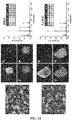
- FIG. 19 shows a CV measurement result of the materials synthesized through the above-described processes, and whether the colors of the materials have changed during the measurement process.
- FIG. 19 shows redox potentials and peak currents which are clearly distinguished according to the structure and composition of the synthesized materials.
- Images shown in left and right columns of FIG. 19 show compounds and chemically oxidized powders, respectively. As confirmed in FIG. 19 , an initial color of electroinactive compounds was maintained even after oxidation, but the color change was noticeable in the case of KTiP 2 O 7 , KVP 2 O 7 , and KMoP 2 O 7 .
- FIG. 20 shows constant current charge and discharge results for KTiP 2 O 7 , KVP 2 O 7 , and KM ⁇ P 2 O 7 . As confirmed in FIGS. 20A (KTiP 2 O 7 ) and 20B (KMoP 2 O 7 ), these two materials exhibited a very low discharge capacity.
- the positive electrode active material according to Examples (KVP 2 O 7 ) of the present invention exhibited an improved discharge capacity as compared with the two materials.
- FIG. 21 shows results of examining shapes and compositions of KVP 2 O 7 and K 1-x VP 2 O 7 -chemically oxidized KVP 2 O 7 with NO 2 BF 4 using field emission scanning electron microscopy (FESEM) and energy dispersive X-ray spectroscopy (EDX).
- FESEM field emission scanning electron microscopy
- EDX energy dispersive X-ray spectroscopy
- the synthesized KVP 2 O 7 powder had a shape which did not grow in a specific direction, and a particle size thereof was in a range of 1 um to 3 um. As confirmed in FIG. 21 , such a shape was retained even after performing chemical oxidation by NO 2 BF 4 .
- FIG. 22 shows X-ray diffraction (XRD) analysis results for KVP 2 O 7 and K 0.4 VP 2 O 7 .
- a crystal structure of K 0.4 VP 2 O 7 was completely different from a crystal structure of KVP 2 O 7 .
- Electronic conductivity measured by a two-point probe method is also changed such that the electronic conductivity of 10 -9 S/cm of KVP 2 O 7 rapidly changes to about 10 -5 S/cm through the phase transition, which may be advantageous for fast discharge.
- the crystal structure of K 0.4 VP 2 O 7 was not stable at high temperature.
- FIG. 22C shows a result of heat treatment of K 0.4 VP 2 O 7 at 800°C under 5% H 2 /N 2 , and as shown in FIG. 22C , the pattern and color were recovered to be the same as those of the initial KVP 2 O 7 . Accordingly, the K 0.4 VP 2 O 7 phase is likely to be a metastable phase in which local energy is minimally stabilized.
- FIG. 23 shows the difference in forms of PO 4 tetrahedra of a K 0.4 VP 2 O 7 phase and a KVP 2 O 7 phase when projected along the P1-P2 bonding.
- FIG. 24 shows results of examining a structural change of the positive electrode active material through synchrotron in-situ XRD analysis during charging and discharging processes. As confirmed in FIG. 24 , a phase transition from P2 1 /c to P-1 occurred during discharging, and a recovery to P2 1 /c occurred during charging. That is, a reversible phase transition occurred during electrochemical charge and discharge.
- phase transition from P2 1 /c to P-1 did not occur completely at the electrochemical charging of 20°C unlike chemical oxidation, which is consistent with the result of a relatively low reversible capacity at 20°C (see FIG. 20 ).
- FIG. 25A shows changes in the first charge and discharge profile when the current density was increased from 0.25 C to 10 C at 50°C. As confirmed in FIG. 25A , a maximum discharge capacity of 60 mAh/g was obtained at 0.25 C, and the electrochemical charge and discharge results indicate that 0.6K + may be reversibly deintercalated/intercalated as in the above-described chemical oxidation.
- the increase of the current density induces an increase of an overvoltage, thereby restricting the high potential redox reaction to lower the discharge capacity.
- the high potential discharge capacity was continuously decreased according to the current density and reached a reversible capacity of 37 mAh/g at 10.0 C.
- Ds are relatively low (about 2 to 4 ⁇ 10 -11 cm 2 /s), but a sharp increase in Ds occurs at a potential gradient of about 4.45 V.
- Ds tend to suddenly decrease and then steadily increase.
- a mean D value was about 3 ⁇ 10 -11 cm 2 /s at 50, which was not so low that the transport of large size K + of KVP 2 O 7 was not significantly hindered. This value was somewhat higher compared to LiFePO 4 (10 -14 ⁇ 10 -15 cm 2 /s) and LiMn 2 O 4 (10 -11 ⁇ 10 -9 cm 2 /s).
- the rapid K + diffusivity of KVP 2 O 7 according to Examples of the present invention appears to be a major factor in maintaining high energy density during fast charge and discharge in KVP 2 O 7 .
- KVP 2 P 7 exhibited excellent cycle characteristics due to the strong P 2 O 7 network.
Abstract
Description
- The present invention relates to a positive electrode active material for a potassium secondary battery and a potassium secondary battery including the same.
- Depletion of fossil fuels such as petroleum and coal and environmental pollution caused by the use of the fossil fuels require efficient use of energy produced, and energy produced in an eco-friendly method, such as solar energy and wind energy do not have a constant production amount, and accordingly, interest in large-capacity secondary batteries that store the produced energy to cope with the required demand is increasing.
- The secondary batteries, which have received the most attention until now, are lithium secondary batteries, and the lithium secondary batteries are not only rapidly and increasingly used for power supply of portable electronic devices and electric vehicles by allowing electric energy to be charged and discharged over a long period of time at a high density, but also widely used for energy storage systems (ESSs) configured to store electric power produced in a power plant and efficiently manage electric energy produced by methods such as solar energy and wind energy.
- However, since lithium used in the lithium secondary batteries is a limited resource localized in specific areas, there is a problem that it is not only expensive but also difficult to cope with growing demands for batteries and energy storage devices.
- To resolve the above-described problem, there is a growing interest in non-lithium batteries which do not use lithium as a main raw material, and the non-lithium batteries use alkali metals, alkaline earth metals, Group 3A metals, transition metals, and the like except for lithium.
- Secondary batteries based on alkali metal ions such as Na+ and K+, which have a large amount of reserves, are considerably inexpensive as compared with the lithium-ion batteries, and thus may be suitably used, particularly, for batteries for ESSs.
- Among these, metal oxides having a layered structure in the form of O3, P2 and P3, Prussian blue having an open framework structure, phosphates, fluorophosphates, pyrophosphates, sulfides, and the like have been developed as positive electrode active materials for sodium-ion batteries, but materials that meet a sufficient level of capacity, lifespan, and the like are still rare.
- Potassium is similar in potential to lithium, and mobility of potassium ions is excellent, and thus a potential for secondary batteries is considerable, but little attention has been received until now. Accordingly, studies on a Prussian blue-like material (KFeIIIFeII(CN)6) disclosed in the following patent document have been mainly and actively conducted as a positive electrode active material for a potassium secondary battery, and it has been known that materials such as KxTiS2, KxCoO2, KxMnO2, and the like may also be used as the positive electrode active material, but as compared with lithium secondary batteries or the sodium secondary batteries, positive electrode active materials for potassium secondary batteries have been rarely studied.
- The present invention is directed to providing a material which may be used as a positive electrode active material for a potassium secondary battery and a potassium secondary battery including the material.
- One aspect of the present invention provides a positive electrode active material for a potassium secondary battery, which is a crystalline material including K, transition metals, P, and O, and the material includes, as a main phase, a phase showing a diffraction peak having a relative intensity of 5% or more in a range of Bragg angles (2θ) of an X-ray diffraction pattern of 14.7° to 15.7°, 22.1° to 23.1°, 25.5° to 26.5°, and 29.7° to 30.8°, when a relative intensity of a diffraction peak having the strongest intensity is taken as 100% in the powder X-ray diffraction pattern of the material.
- Another aspect of the present invention provides a potassium secondary battery including a positive electrode, a negative electrode, and an electrolyte, and the positive electrode includes a positive electrode active material including K, transition metals, P, and O, and the material includes, as a main phase, a phase showing a diffraction peak having a relative intensity of 5% or more in a range of Bragg angles (2θ) of an X-ray diffraction pattern of 14.7° to 15.7°, 22.1° to 23.1°, 25.5° to 26.5°, and 29.7° to 30.8°, when a relative intensity of a diffraction peak having the strongest intensity is taken as 100% in the powder X-ray diffraction pattern.
- According to one embodiment of the present invention, potassium ions are easily reversibly intercalated/de-intercalated, have excellent structural stability and are excellent in charge and discharge cycle characteristics, and thus it is expected to be suitably used, especially, for an energy storage system (ESS).
- Further, a positive electrode active material for a potassium secondary battery according to one embodiment of the present invention can use a non-aqueous electrolyte.
- According to another embodiment of the present invention, there is provided a potassium secondary battery including the positive electrode active material for a potassium secondary battery.
-
-
FIG. 1 shows a portion where Bragg angles (2θ) of a X-ray diffraction pattern of a positive electrode active material synthesized according to Example 1 of the present invention are 14.7° to 15.7°, 22.1° to 23.1°, 25.5° to 26.5°, and 29.7° to 30.8°. -
FIG. 2 shows X-ray diffraction patterns of positive electrode active materials synthesized according to Examples 1 to 18 of the present invention. -
FIG. 3 shows X-ray diffraction patterns of positive electrode active materials synthesized according to Examples 19 to 36 of the present invention. -
FIG. 4 shows a X-ray diffraction pattern of a positive electrode active material synthesized according to Example 37 of the present invention. -
FIG. 5 shows the first charge and discharge results for the positive electrode active materials synthesized according to Examples 1 to 6 of the present invention. -
FIG. 6 shows the first charge and discharge results for the positive electrode active materials synthesized according to Examples 7 to 12 of the present invention. -
FIG. 7 shows the first charge and discharge results for the positive electrode active materials synthesized according to Examples 13 to 18 of the present invention. -
FIG. 8 shows the first charge and discharge results for the positive electrode active materials synthesized according to Examples 19 to 24 of the present invention. -
FIG. 9 shows the first charge and discharge results for the positive electrode active materials synthesized according to Examples 25 to 30 of the present invention. -
FIG. 10 shows the first charge and discharge results for the positive electrode active materials synthesized according to Examples 31 to 36 of the present invention. -
FIG. 11 shows the first charge and discharge result for the positive electrode active material synthesized according to Example 37 of the present invention. -
FIG. 12 shows 10th charge and discharge results for the positive electrode active materials synthesized according to Examples 1 to 6 of the present invention. -
FIG. 13 shows 10th charge and discharge results for the positive electrode active materials synthesized according to Examples 7 to 12 of the present invention. -
FIG. 14 shows 10th charge and discharge results for the positive electrode active materials synthesized according to Examples 13 to 18 of the present invention. -
FIG. 15 shows 10th charge and discharge results for the positive electrode active materials synthesized according to Examples 19 to 24 of the present invention. -
FIG. 16 shows 10th charge and discharge for the positive electrode active materials synthesized according to Examples 25 to 30 of the present invention. -
FIG. 17 shows 10th charge and discharge results for the positive electrode active materials synthesized according to Examples 31 to 36 of the present invention. -
FIG. 18 shows a 10th charge and discharge result for the positive electrode active material synthesized according to Example 37 of the present invention. -
FIG. 19 shows cyclic voltammograms of the positive electrode active materials according to Examples and Comparative Examples of the present invention and whether the colors of the materials have changed during the process. -
FIG. 20 shows results after constant current charging and discharging for KTiP2O7, KVP2O7, and KMοP2O7. -
FIG. 21 shows results of examining shapes and compositions of KVP2O7 and K1-xVP2O7 -chemically oxidized KVP2O7 with NO2BF4 using field emission scanning electron microscopy (FESEM) and energy dispersive X-ray spectroscopy (FESEM). -
FIG. 22 shows X-ray diffraction (XRD) analysis results for KVP2O7 and K0.4VP2O7. -
FIG. 23 shows the difference in forms of PO4 tetrahedra of a K0.4VP2O7 phase and a KVP2O7 phase when projected along the P1-P2 bonding. -
FIG. 24 shows results of examining a structural change of the positive electrode active material during charging and discharging processes through synchrotron in-situ XRD analysis. -
FIG. 25 shows results of evaluating battery characteristics of coin cells using positive electrode active materials manufactured according to Examples of the present invention. - Hereinafter, positive electrode active materials according to exemplary embodiments and potassium secondary batteries provided with positive electrodes including the same will be described in more detail. However, the following embodiments are presented as examples, whereby the present invention is not limited thereto, and the present invention is defined by the scope of the following claims to be described later.
- A positive electrode active material for a potassium secondary battery according to the present invention includes K, transition metals, P, and O, and may be a material including, as a main phase, a phase showing a diffraction peak having a relative intensity of 5% or more in a range of Bragg angles (2θ) of an X-ray diffraction pattern of 14.7° to 15.7°, 22.1° to 23.1°, 25.5° to 26.5°, and 29.7° to 30.8°, when a relative intensity of a diffraction peak having the strongest intensity is taken as 100% in the powder X-ray diffraction pattern.
- Such a positive electrode active material is made of an inorganic material having a relatively excellent stability as compared with an organic material, and when the positive electrode active material has the X-ray diffraction pattern, the positive electrode active material has a tunnel-like crystal structure, so that potassium ions having a relatively greater ionic radius than lithium or sodium may be easily intercalated and deintercalated, and structural stability becomes excellent, and accordingly, charge and discharge cycle characteristics become excellent and a battery using a non-aqueous electrolyte may be constituted.
- Further, a positive electrode active material for a potassium secondary battery may further include one or more selected from Li, Na, Rb, Al, La, Gd, and Lu.
- Further, the positive electrode active material may be a compound represented by the following
Formula 1,
[Formula 1] (K1-aM1a)(M21-bM3b)PcOd
wherein in Formula 1, 0≤a≤0.2, 0≤b≤0.7, 1.8≤c≤2.2, and 6.8≤d≤7.2, and M1 is at least one element selected from alkali metal elements and alkaline earth metals other than K, and M2 and M3 are at least one element selected from transition metals. - For example, the positive electrode active material may be a compound represented by the following Formula 2,
[Formula 2] (K1-aM1a)(M21-bM3b)PcOd
wherein in Formula 2, 0≤a≤0.2, 0≤b≤0.7, 1.8≤c≤2.2, and 6.8≤d≤7.2, and M1 is at least one element selected from alkali metal elements and alkaline earth metals, other than K, and M2 and M3 are at least one element selected from V, Ti, Fe, Cr, Mo, Mn, Co, Ni, Al, La, Gd, and Lu. - For example, the positive electrode active material may be a compound represented by the following Formula 3,
[Formula 3] (K1-aMla)(V1-bM3b)PcOd
wherein in Formula 3, 0≤a≤0.2, 0≤b≤0.7, 1.8≤c≤2.2, and 6.8≤d≤7.2, and M1 is at least one element selected from alkali metal elements and alkaline earth metal elements other than K, and M3 is at least one element selected from Ti, Fe, Cr, Mo, Mn, Co, Ni, Al, La, Gd, and Lu. - For example, the positive electrode active material may specifically be KVP2O7, KTiP2O7, KCrP2O7, KFeP2O7, or KMoP2O7.
- According to one embodiment of the present invention, there is provided a positive electrode active material for a potassium secondary battery, which is a crystalline material including K, transition metals, P and O, and in which a phase transition to a monoclinic crystal structure and a triclinic crystal structure is dynamically performed in a charge and discharge process.
- A positive electrode active material according to the present invention may obtain improved capacity and excellent high-rate characteristics through a process in which a phase transition to a monoclinic crystal structure and a triclinic crystal structure is dynamically performed in a charge and discharge process.
- Further, the crystalline material may have a monoclinic crystal structure in a charged state and a triclinic crystal structure in a discharged state.
- Further, the crystalline material may have a composition of
Formula 1 in a charged state and a composition ofFormula 2 in a discharged state,
[Formula 1] (K1-aM1a)(V1-bM2b)PcOd
wherein, 0≤a≤0.1, 0≤b≤0.7, 1.8≤c≤2.2, and 6.8≤d≤7.2, and M1 is one or more among alkali metal elements other than K, and M2 is at least one element selected from Ti, Fe, Cr, Mo, Mn, Co, Ni, Al, La, Gd, and Lu,
[Formula 2] (K1-aM1a)(V1-b-eM2b)PcOd
wherein, 0≤a≤0.1, 0≤b≤0.7, 1.8≤c≤2.2, 6.8≤d≤7.2, and 0.55≤e≤0.65, and M1 is one or more among alkali metal elements other than K, and M2 is at least one element selected from Ti, Fe, Cr, Mo, Mn, Co, Ni, Al, La, Gd, and Lu. - Further, the crystalline material may have a space group P21/c in a charged state and a
space group P 1 in a discharged state. - Further, the crystalline material may have a composition of KVP2O7 in a charged state and a composition of K1-xVP2O7(0.55≤x≤0.65) in a discharged state.
- Further, according to another embodiment of the present invention, there may be provided a potassium secondary battery including a positive electrode having a positive electrode active material containing the above-described composition and crystal structure, a negative electrode disposed to be spaced a certain distance from the positive electrode, a separator disposed between the positive electrode and the negative electrode, and an electrolyte filled between the positive electrode and the negative electrode, and the separator.
- The positive electrode may include a current collector and a positive electrode active material layer formed on the current collector.
- The current collector may include a metal current collector, for example, aluminum foil.
- The positive electrode active material layer may be prepared as a composition in the form of a mixture of a positive electrode active material powder having the above-described composition, a conductive material, a binder, and a solvent, molded, and laminated on the metal current collector or coated on the metal current collector to manufacture a positive electrode.
- However, the present invention is not limited to the above-described method but may be a form other than the above-described method.
- As the conductive material, carbon black, graphite fine particles, or the like may be used, but the present invention is not limited thereto, and any conductive material which can be used in the art may be used. For example, graphite such as natural graphite and artificial graphite; carbon black such as acetylene black, Ketjen black, channel black, furnace black, lamp black, and thermal black; conductive fibers such as carbon fibers and metal fibers; metallic powders such as aluminum or nickel powder; conductive whiskers such as zinc oxide and potassium titanate; conductive metal oxides such as titanium oxide; conductive materials such as polyphenylene derivatives; and the like may be used.
- The binder may include a vinylidene fluoride-hexafluoropropylene copolymer, polyvinylidene fluoride, polyacrylonitrile, polymethylmethacrylate, polytetrafluoroethylene, and mixtures thereof, or styrene butadiene rubber-based polymers, or the like, but the present invention is not limited thereto, and any binder which can be used in the art may be used.
- As the solvent, N-methylpyrrolidone, acetone, water, or the like may be used, but the present invention is not limited thereto, and any solvent which can be used in the art may be used. Contents of the positive electrode active material, the conductive material, the binder, and the solvent may be adjusted in accordance with characteristics required for a potassium secondary battery, and one or more thereof may not be used as required.
- The negative electrode may include a current collector and a negative electrode active material layer formed on the current collector.
- The negative electrode active material layer may be manufactured by coating a mixture prepared by mixing a negative electrode active material powder, a conductive material, a binder, and a solvent, directly on a metal current collector, and drying or casting the negative electrode active material composition on a separate substrate, separating and laminating the negative electrode active material composition separated from the substrate on the metal current collector.
- The negative electrode active material is not particularly limited as long as it is used in a potassium secondary battery and is capable of reversible intercalation and deintercalation of potassium ions, for example, includes potassium metal, a potassium alloy, a carbon-based material, or the like.
- As a material capable of reversibly intercalating and de-intercalating the potassium ions, any carbon-based negative electrode active material which is a carbon-based material and generally used in conventional lithium secondary batteries may be used. For example, there is crystalline carbon, amorphous carbon, or mixtures thereof. Examples of the crystalline carbon may include amorphous, platy, flaky, spherical, or fibrous natural graphite or artificial graphite, and examples of the amorphous carbon may include, soft carbon (low-temperature calcined carbon) or hard carbon, mesophase pitch carbide, calcined coke, or the like.
- Regarding the contents of the negative electrode active material, the conductive material, the binder, and the solvent, the contents of the conductive material, the binder, and the solvent may be controlled or some of which may be omitted depending on the use and configuration of a potassium secondary battery.
- The separator may have an excellent electrolyte-retaining property while having low resistance against the movement of ions included in the electrolyte.
- The separator may be in the form of a nonwoven fabric or a woven fabric selected from, for example, glass fiber, polyester, Teflon, polyethylene, polypropylene, polytetrafluoroethylene (PTFE), or a combination thereof, and include polyethylene, polypropylene, and the like which are widely used in lithium-ion batteries.
- The electrolyte is preferably a non-aqueous electrolyte and may be made of an organic material in which a potassium salt is dissolved in an organic solvent.
- The organic solvent may be any organic solvent that can be used in the art. For example, there are propylene carbonate, ethylene carbonate, fluoroethylene carbonate, butylene carbonate, dimethyl carbonate, diethyl carbonate, methyl ethyl carbonate, methyl propyl carbonate, ethyl propyl carbonate, methyl isopropyl carbonate, dipropyl carbonate, dibutyl carbonate, benzonitrile, acetonitrile, tetrahydrofuran, 2-methyltetrahydrofuran, gamma-butyrolactone, dioxolane, 4-methyldioxolane, N, N-dimethylformamide, dimethylacetamide, dimethyl sulfoxide, dioxane, 1,2-dimethoxyethane, sulfolane, dichloroethane, chlorobenzene, nitrobenzene, diethylene glycol, dimethyl ether or mixtures thereof.
- The potassium salt may be used without particular limitation as long as it can be used as a potassium salt in the art.
- Further, the electrolyte may be a solid electrolyte such as an organic solid electrolyte or an inorganic solid electrolyte. When the solid electrolyte is used, the solid electrolyte may also serve as a separator.
- The positive electrode, the negative electrode, the separator, and the electrolyte are accommodated in a case in the same manner as a general method for manufacturing batteries, such as lithium secondary batteries, and finally made into a battery.
- Here, it is manufactured by a method in which the positive electrode, the negative electrode, and the separator are stacked and wound, or folded in multiple layers to be accommodated in a case, and then the electrolyte is injected into the case and sealed. Various materials such as metal and plastic may be used as the material of the case, and the case may have various shapes such as a cylindrical shape, a prismatic shape, a pouch shape, and the like.
- The present invention will be described in more detail through the following Examples, but the present invention should not be construed as being limited to the following Examples.
- Hereinafter, a method for manufacturing a positive electrode active material for a potassium secondary battery according to the present invention will be described in detail.
- In the case of K, V, Ti, Fe, Cr, Mo, Mn, Co, Ni, and P which are main components of raw materials for manufacturing a positive electrode active material for a potassium secondary battery, potassium carbonate (K2CO3), vanadium oxide (V2O5), titanium dioxide (TiO2), iron oxide (Fe2O3), chromium oxide (Cr2O3), molybdenum oxide (MO2O5), manganese oxide (Mn2O3), cobalt oxide (Co2O3), nickel oxide (NiO), and ammonium phosphate ((NH4)HPO4) powder were used.
- The raw materials were weighed and mixed so as to have a certain composition, and at this time, an amount of the mixture per sample was adjusted to be 3 g. The mixing of the raw materials as described above was performed manually for 30 minutes in an air atmosphere.
- Samples of the mixture obtained as described above were subjected in an air atmosphere or a nitrogen gas atmosphere, in which H2 gas is 0 to 25% and the main component is nitrogen gas at atmospheric pressure or higher and 20 atm or lower. Further, a calcination temperature is preferably 700°C to 1100°C, and more preferably 800°C or more to obtain a high-quality positive electrode active material for a potassium secondary battery. Further, a calcination time may be in a range of 30 minutes to 100 hours, and preferably 2 hours to 24 hours considering the quality and productivity.
- Hereinafter, the positive electrode active material for a potassium secondary battery of the present invention will be described in detail with reference to more specific Examples.
- To obtain a raw material powder of a positive electrode active material composition for a potassium secondary battery of Example 1, each of 0.4888 g of K2CO3, 0.6432 g of V2O5, and 1.8680 g of (NH4)2HPO4 was weighed and then they were manually mixed using a mortar in an air atmosphere to obtain 3 g of a raw material powder mixture. 3 g of the raw material powder mixture mixed as described above was put into a crucible and subjected to a calcination process in which a mixed gas containing nitrogen gas as a main component and 15% H2 gas was flowed at a rate of 500 cc/minute in a furnace and heated at 800°C for 24 hours, followed by pulverization to obtain the positive electrode active material composition for a potassium secondary battery.
- Further, a potassium half-cell was manufactured to evaluate the performance of the manufactured positive electrode active material for a potassium secondary battery. In order to manufacture the potassium half-cell, positive electrode active material powder composed of KVP2O7 synthesized as described above, carbon powder (Super P) as a conductive material, and polyvinylidene fluoride (PVDF) as a binder were mixed in a weight ratio of 75:15:15, and N-methyl pyrrolidone (NMP) as a solvent was added thereto, and mixed and stirred to prepare a positive electrode slurry. This slurry was applied to aluminum foil as a current collector, and then dried in an oven at 120°C for at least 8 hours to prepare a positive electrode. Further, potassium foil was used as a negative electrode and a reference electrode.
- A separator composed of a porous polyethylene membrane was disposed between the positive electrode and the negative electrode manufactured as described above, and then an electrolyte ((0.5 M KPF6/ fluoroethylene carbonate (FEC): ethyl methyl carbonate (EMC)) was injected thereinto to manufacture a coin cell.
- A positive electrode was manufactured in the same manner as in Example 1 except that the composition of the raw material powder was changed to 0.4952 g of K2CO3, 0.3258 g of V2O5, 0.2863 g of TiO2, and 1.8927 g of (NH4)2HPO4 to manufacture a coin cell.
- A positive electrode was manufactured in the same manner as in Example 1 except that the composition of the raw material powder was changed to 0.4952 g of K2CO3, 0.3259 g of V2O5, 0.2861 g of Fe2O3, and 1.8929 g of (NH4)2HPO4 to manufacture a coin cell.
- A positive electrode was manufactured in the same manner as in Example 1 except that the composition of the raw material powder was changed to 0.4528 g of K2CO3, 0.2979 g of V2O5, 0.5188 g of CrCl3, and 1.7305 g of (NH4)2HPO4 to manufacture a coin cell.
- A positive electrode was manufactured in the same manner as in Example 1 except that the composition of the raw material powder was changed to 0.4683 g of K2CO3, 0.3082 g of V2O5, 0.4335 g of MoO2, and 1.7900 g of (NH4)2HPO4 to manufacture a coin cell.
- A positive electrode was manufactured in the same manner as in Example 1 except that the composition of the raw material powder was changed to 0.4958 g of K2CO3, 0.3262 g of V2O5, 0.2832 g of Mn2O3, and 1.8949 g of (NH4)2HPO4 to manufacture a coin cell.
- A positive electrode was manufactured in the same manner as in Example 1 except that the composition of the raw material powder was changed to 0.4950 g of K2CO3, 0.3257 g of V2O5, 0.2875 g of Co3O4, and 1.8918 g of (NH4)2HPO4 to manufacture a coin cell.
- A positive electrode was manufactured in the same manner as in Example 1 except that the composition of the raw material powder was changed to 0.4983 g of K2CO3, 0.3279 g of V2O5, 0.2693 g of NiO, and 1.9045 g of (NH4)2HPO4 to manufacture a coin cell.
- A positive electrode was manufactured in the same manner as in Example 1 except that the composition of the raw material powder was changed to 0.4974 g of K2CO3, 0.2182 g of V2O5, 0.1917 g of TiO2, 0.1916 g of Fe2O3, and 1.9011 g of (NH4)2HPO4 to manufacture a coin cell.
- A positive electrode was manufactured in the same manner as in Example 1 except that the composition of the raw material powder was changed to 0.4680 g of K2CO3, 0.2053 g of V2O5, 0.1804 g of TiO2, 0.3575 g of CrCl3, and 1.7888 g of (NH4)2HPO4 to manufacture a coin cell.
- A positive electrode was manufactured in the same manner as in Example 1 except that the composition of the raw material powder was changed to 0.4790 g of K2CO3, 0.2101 g of V2O5, 0.1846 g of TiO2, 0.2956 g of MnO2, and 1.8307 g of (NH4)2HPO4 to manufacture a coin cell.
- A positive electrode was manufactured in the same manner as in Example 1 except that the composition of the raw material powder was changed to 0.4978 g of K2CO3, 0.2184 g of V2O5, 0.1918 g of TiO2, 0.1895 g of Mn2O3, and 1.9025 g of (NH4)2HPO4 to manufacture a coin cell.
- A positive electrode was manufactured in the same manner as in Example 1 except that the composition of the raw material powder was changed to 0.4972 g of K2CO3, 0.2181 g of V2O5, 0.1916 g of TiO2, 0.1925 g of Co3O4, and 1.9005 g of (NH4)2HPO4 to manufacture a coin cell.
- A positive electrode was manufactured in the same manner as in Example 1 except that the composition of the raw material powder was changed to 0.4995 g of K2CO3, 0.2191 g of V2O5, 0.1925 g of TiO2, 0.1799 g of NiO, and 1.9090 g of (NH4)2HPO4 to manufacture a coin cell.
- A positive electrode was manufactured in the same manner as in Example 1 except that the composition of the raw material powder was changed to 0.4680 g of K2CO3, 0.2053 g of V2O5, 0.1803 g of Fe2O3, 0.3575 g of CrCl3, and 1.7889 g of (NH4)2HPO4 to manufacture a coin cell.
- A positive electrode was manufactured in the same manner as in Example 1 except that the composition of the raw material powder was changed to 0.4790 g of K2CO3, 0.2101 g of V2O5, 0.1845 g of Fe2O3, 0.2956 g of MnO2, and 1.8308 g of (NH4)2HPO4 to manufacture a coin cell.
- A positive electrode was manufactured in the same manner as in Example 1 except that the composition of the raw material powder was changed to 0.4978 g of K2CO3, 0.2184 g of V2O5, 0.1917 g of Fe2O3, 0.1895 g of Mn2O3, and 1.9026 g of (NH4)2HPO4 to manufacture a coin cell.
- A positive electrode was manufactured in the same manner as in Example 1 except that the composition of the raw material powder was changed to 0.4973 g of K2CO3, 0.2181 g of V2O5, 0.1915 g of Fe2O3, 0.1925 g of Co3O4, and 1.9006 g of (NH4)2HPO4 to manufacture a coin cell.
- A positive electrode was manufactured in the same manner as in Example 1 except that the composition of the raw material powder was changed to 0.4995 g of K2CO3, 0.2191 g of V2O5, 0.1924 g of Fe2O3, 0.1800 g of NiO, and 1.9091 g of (NH4)2HPO4 to manufacture a coin cell.
- A positive electrode was manufactured in the same manner as in Example 1 except that the composition of the raw material powder was changed to 0.4517 g of K2CO3, 0.1981 g of V2O5, 0.3450 g of CrCl3, 0.2788 g of MoO2, and 1.7264 g of (NH4)2HPO4 to manufacture a coin cell.
- A positive electrode was manufactured in the same manner as in Example 1 except that the composition of the raw material powder was changed to 0.4684 g of K2CO3, 0.2055 g of V2O5, 0.3578 g of CrCl3, 0.1783 g of Mn2O3, and 1.7901 g of (NH4)2HPO4 to manufacture a coin cell.
- A positive electrode was manufactured in the same manner as in Example 1 except that the composition of the raw material powder was changed to 0.4679 g of K2CO3, 0.2052 g of V2O5, 0.3574 g of CrCl3, 0.1812 g of Co3O4, and 1.7883 g of (NH4)2HPO4 to manufacture a coin cell.
- A positive electrode was manufactured in the same manner as in Example 1 except that the composition of the raw material powder was changed to 0.4699 g of K2CO3, 0.2061 g of V2O5, 0.3589 g of CrCl3, 0.1693 g of NiO, and 1.7958 g of (NH4)2HPO4 to manufacture a coin cell.
- A positive electrode was manufactured in the same manner as in Example 1 except that the composition of the raw material powder was changed to 0.4793 g of K2CO3, 0.2103 g of V2O5, 0.2958 g of MoO2, 0.1825 g of Mn2O3, and 1.8321 g of (NH4)2HPO4 to manufacture a coin cell.
- A positive electrode was manufactured in the same manner as in Example 1 except that the composition of the raw material powder was changed to 0.4789 g of K2CO3, 0.2101 g of V2O5, 0.2955g of MoO2, 0.1854 g of Co3O4, and 1.8302 g of (NH4)2HPO4 to manufacture a coin cell.
- A positive electrode was manufactured in the same manner as in Example 1 except that the composition of the raw material powder was changed to 0.4809 g of K2CO3, 0.2110 g of V2O5, 0.2968 g of MoO2, 0.1733 g of NiO, and 1.8381 g of (NH4)2HPO4 to manufacture a coin cell.
- A positive electrode was manufactured in the same manner as in Example 1 except that the composition of the raw material powder was changed to 0.4976 g of K2CO3, 0.2183 g of V2O5, 0.1895 g of Mn2O3, 0.1927 g of Co3O4, and 1.9019 g of (NH4)2HPO4 to manufacture a coin cell.
- A positive electrode was manufactured in the same manner as in Example 1 except that the composition of the raw material powder was changed to 0.4999 g of K2CO3, 0.2193 g of V2O5, 0.1903 g of Mn2O3, 0.1801 g of NiO, and 1.9105 g of (NH4)2HPO4 to manufacture a coin cell.
- A positive electrode was manufactured in the same manner as in Example 1 except that the composition of the raw material powder was changed to 0.4993 g of K2CO3, 0.2190 g of V2O5, 0.1933 g of Co3O4, 0.1799 g of NiO, and 1.9084 g of (NH4)2HPO4 to manufacture a coin cell.
- A positive electrode was manufactured in the same manner as in Example 1 except that the composition of the raw material powder was changed to 0.4432 g of K2CO3, 0.6481 g of V2O5, 0.0263 g of Li2CO3, and 1.8823 g of (NH4)2HPO4 to manufacture a coin cell.
- A positive electrode was manufactured in the same manner as in Example 1 except that the composition of the raw material powder was changed to 0.4416 g of K2CO3, 0.6456 g of V2O5, 0.0376 g of Na2CO3, and 1.8752 g of (NH4)2HPO4 to manufacture a coin cell.
- A positive electrode was manufactured in the same manner as in Example 1 except that the composition of the raw material powder was changed to 0.4351 g of K2CO3, 0.6362 g of V2O5, 0.0808 g of Rb2O3, and 1.8478 g of (NH4)2HPO4 to manufacture a coin cell.
- A positive electrode was manufactured in the same manner as in Example 1 except that the composition of the raw material powder was changed to 0.4934 g of K2CO3, 0.5844 g of V2O5, 0.0364 g of V2O3, and 1.8858 g of (NH4)2HPO4 to manufacture a coin cell.
- A positive electrode was manufactured in the same manner as in Example 1 except that the composition of the raw material powder was changed to 0.4806 g of K2CO3, 0.5692 g of V2O5, 0.1133 g of Al2O3, and 1.8369 g of (NH4)2HPO4 to manufacture a coin cell.
- A positive electrode was manufactured in the same manner as in Example 1 except that the composition of the raw material powder was changed to 0.4786 g of K2CO3, 0.5668 g of V2O5, 0.1255 g of La2O3, and 1.8291 g of (NH4)2HPO4 to manufacture a coin cell.
- A positive electrode was manufactured in the same manner as in Example 1 except that the composition of the raw material powder was changed to 0.4766 g of K2CO3, 0.5645 g of V2O5, 0.1372 g of Gd2O3, and 1.8217 g of (NH4)2HPO4 to manufacture a coin cell.
- A positive electrode was manufactured in the same manner as in Example 1 except that the composition of the raw material powder was changed to 0.4345 g of K2CO3, 0.9050 g of MoO2, and 1.6605 g of (NH4)2HPO4 to manufacture a coin cell.
- In order to analyze a crystal structure of the positive electrode active materials synthesized according to Examples 1 to 36, a powder XRD analysis was performed, and the results are shown in
FIGS. 1 to 3 . - The XRD analysis was performed using a diffractometer ((manufactured by Rigaku Co., Ltd., model: D/MAX2500V/PC powder diffractometer, λ= 1.5405Å) using α radiation of copper-potassium (Cu-K), under the condition that 2θ was in a range of 10° to 80 ° and changed at 0.2° per minute.
-
FIG. 1 shows a result of XRD diffraction analysis according to Example 1 of the present invention having a crystal structure showing a diffraction peak having a relative intensity of 5% or more in a range of Bragg angles (2θ) of an x-ray diffraction pattern of 14.7° to 15.7°, 22.1° to 23.1°, 25.5° to 26.5°, and 29.7° to 30.8°, which is specified in the claims of the present application. - As shown in
FIGS. 2 to 4 , Example 2 to Example 37 of the present invention also have a crystal structure showing a diffraction peak having a relative intensity of 5% or more in a range of Bragg angles (2θ) of 14.7° to 15.7°, 22.1° to 23.1°, 25.5° to 26.5°, and 29.7° to 30.8°, as in Example 1. - Battery characteristics were evaluated using the coin cells manufactured as described above, and the results are shown in
FIGS. 5 to 18 , and the numbers shown inFIGS. 4 to 18 indicate the order of Examples. - Conditions for evaluating the battery characteristics were C-rate: 12 mA/g and Cutoff: 2.0 V to 5.4 V.
- Table 1 below shows capacities of a 1st cycle and a 10th cycle of the coin cells using the positive electrodes manufactured according to Examples 1 to 37.
[Table 1] Examples 1st cycle Capacity (mAh/g) 10th cycle Capacity (mAh/g) Charge Discharge Charge Discharge 1 117.5479 51.2634 65.8395 50.4012 2 78.4740 32.3062 45.0536 37.0842 3 89.4762 21.3546 46.4025 28.9539 4 56.5535 19.7825 32.3475 26.3301 5 56.5535 19.7825 32.3475 26.3301 6 69.7685 20.6473 32.2046 24.2256 7 174.3166 29.2949 50.7070 32.6744 8 270.5535 45.6793 49.9893 35.2444 9 253.4519 26.4667 36.9736 22.7879 10 68.4465 20.1204 31.3705 24.0434 11 187.1293 47.4293 49.6825 33.4117 12 36.7565 7.5408 10.6169 8.5019 13 36.7565 7.5408 10.6169 8.5019 14 286.0406 38.9994 37.7916 31.3147 15 182.0785 14.6451 24.1489 12.7888 16 242.3889 16.4903 79.7147 34.9506 17 117.0702 17.5034 26.0003 16.1618 18 242.2863 13.0562 35.6631 25.7841 19 329.7233 24.8532 34.0221 17.0443 20 631.0279 34.4352 56.9538 29.7499 21 21.9084 5.3025 12.8840 9.1126 22 754.5139 31.6436 37.7865 21.5670 23 257.4543 31.9925 41.2541 25.0494 24 711.8794 42.0565 80.6237 41.9073 25 1044.5680 53.9011 75.4187 41.9463 26 864.5000 55.2004 63.4230 35.6992 27 411.7310 18.1105 32.4082 16.6592 28 221.5977 34.1472 31.7954 20.1695 29 599.0928 24.7310 35.4204 19.8390 30 127.3513 66.2378 67.9234 64.9929 31 87.2183 47.7411 47.1652 44.3857 32 100.9744 53.3868 59.5881 55.4505 33 112.6637 59.8933 66.7075 58.2496 34 109.7573 41.9130 40.8234 37.3324 35 53.2168 16.8569 28.5120 23.7850 36 100.8606 44.7452 42.9312 39.5275 37 95.5956 35.9387 38.4399 34.1995 - As shown in Table 1, it was confirmed that the positive electrodes manufactured according to Examples 1 to 37 of the present invention function as a secondary battery.
- Particularly, in Example 1, Example 30, Example 31, Example 32, and Example 33, since the discharge capacity at the first cycle was more than 50 mAh/g and a rate of decrease in the discharge capacity at the 10th cycle was low, it is expected that a discharge capacity retention rate is excellent.
- The positive electrode active material was synthesized by a solid phase method. As synthesized materials, KTiP2O7, KMoP2O7, KCo(PO3)3, KNi(PO3)3, KCrP2O7, KFeP2O7, K2(VO3)(P2O7)2, K2MnP2O7, and KMnVO4 were synthesized together with KVP2O7 as in Examples of the present invention to confirm the possibility of a positive electrode active material for a potassium secondary battery.
- Here, K2CO3 was used as a potassium precursor, and H2(NH4)PO4 or H(NH4)2PO4 was used as a phosphorus (P) precursor. Various transition metal oxides or carbonates (TiO2, V2O5, Fe2O3, Cr2O3, MoO2, Co3O4, NiO, MnCO3, and MnO) have been used as a precursor of the metal element in each compound.
- Specifically, a starting material was prepared according to the above chemical composition, and the starting material was pulverized and mixed, and sintered at a temperature suitable for each material. Sintering was performed at 800°C under a reducing atmosphere (argon or 15% H2/N2), at 700°C for KCo(PO3)3, 600°C for KNi(PO3)3, and at 1050°C for KCrP2O7.
- Further, a potassium half-cell was manufactured to evaluate the performance of the manufactured positive electrode active material for a potassium secondary battery. In order to manufacture the potassium half-cell, the positive electrode active material powder synthesized as described above, acetylene black as a conductive material, and polyvinylidene fluoride (PVDF) as a binder were mixed at a weight ratio of 65:20:15, and N-methyl pyrrolidone (NMP) as a solvent was added thereto, followed by mixing and stirring to manufacture a positive electrode slurry. The slurry was applied to aluminum foil as a current collector, and then dried in an oven at 120°C for at least 8 hours to prepare a positive electrode. Further, potassium foil was used as a negative electrode and a reference electrode.
- A separator made of a porous polyethylene membrane was disposed between the positive electrode and the negative electrode manufactured as described above, and then an electrolyte (0.5M KPF6/ethylene carbonate (EC):diethyl carbonate (DEC)) was injected thereinto to manufacture a coin cell.
-
FIG. 19 shows a CV measurement result of the materials synthesized through the above-described processes, and whether the colors of the materials have changed during the measurement process. -
FIG. 19 shows redox potentials and peak currents which are clearly distinguished according to the structure and composition of the synthesized materials. - In particular, only KTiP2O7, KVP2O7, and KMοP2O7 showed remarkable redox peak pairs among the synthesized materials. Among these, in the case of K2(VO)3(P2O7)2, K2MnP2O7, and KMnVO4, electroactivity was not observed.
- Images shown in left and right columns of
FIG. 19 show compounds and chemically oxidized powders, respectively. As confirmed inFIG. 19 , an initial color of electroinactive compounds was maintained even after oxidation, but the color change was noticeable in the case of KTiP2O7, KVP2O7, and KMoP2O7. - The correlation between such electrical activity and the color change due to oxidation may be seen as that extraction of K+ in the compound involves specific types of structural relaxation and consequently changes in optical characteristics.
- However, considering the limited theoretical capacity of pyrophosphate, a high redox potential is required to obtain a high energy density, but as confirmed in
FIG. 1 , KTiP2O7 and KMoP2O7 have a problem in that the redox potential is too low. -
FIG. 20 shows constant current charge and discharge results for KTiP2O7, KVP2O7, and KMοP2O7. As confirmed inFIGS. 20A (KTiP2O7) and 20B (KMoP2O7), these two materials exhibited a very low discharge capacity. - In contrast, as confirmed in
FIGS. 20C and 20D , the positive electrode active material according to Examples (KVP2O7) of the present invention exhibited an improved discharge capacity as compared with the two materials. -
FIG. 21 shows results of examining shapes and compositions of KVP2O7 and K1-xVP2O7 -chemically oxidized KVP2O7 with NO2BF4 using field emission scanning electron microscopy (FESEM) and energy dispersive X-ray spectroscopy (EDX). - The synthesized KVP2O7 powder had a shape which did not grow in a specific direction, and a particle size thereof was in a range of 1 um to 3 um. As confirmed in
FIG. 21 , such a shape was retained even after performing chemical oxidation by NO2BF4. - Further, in an EDX elemental analysis, synthesized KVP2O7 particles were analyzed with K0.96VP1.9O7, and a composition of chemically oxidized K1-xVP2O7 was analyzed with K0.39VP1.7O7. Considering the uncertainty of quantification, the compositions of the synthesized and chemically oxidized materials may be seen as KVP2O7 and K0.4VP2O7, respectively. The fact that it is possible to generate K0.4VP2O7 means that KVP2O7 may achieve high capacity.
-
FIG. 22 shows X-ray diffraction (XRD) analysis results for KVP2O7 and K0.4VP2O7. - As confirmed in
FIG. 22 , a crystal structure of K0.4VP2O7 was completely different from a crystal structure of KVP2O7. Electronic conductivity measured by a two-point probe method is also changed such that the electronic conductivity of 10-9S/cm of KVP2O7 rapidly changes to about 10-5S/cm through the phase transition, which may be advantageous for fast discharge. On the other hand, the crystal structure of K0.4VP2O7 was not stable at high temperature. -
FIG. 22C shows a result of heat treatment of K0.4VP2O7 at 800°C under 5% H2/N2, and as shown inFIG. 22C , the pattern and color were recovered to be the same as those of the initial KVP2O7. Accordingly, the K0.4VP2O7 phase is likely to be a metastable phase in which local energy is minimally stabilized. - Phase analysis of the K0.4VP2O7 phase through a powder XRD-based structural analysis process revealed that the K0.4VP2O7 phase was a triclinic phase (space group P-1), which is quite different from KVP2O7 that is a monoclinic phase (space group P21/c).
-
FIG. 23 shows the difference in forms of PO4 tetrahedra of a K0.4VP2O7 phase and a KVP2O7 phase when projected along the P1-P2 bonding. -
FIG. 24 shows results of examining a structural change of the positive electrode active material through synchrotron in-situ XRD analysis during charging and discharging processes. As confirmed inFIG. 24 , a phase transition from P21/c to P-1 occurred during discharging, and a recovery to P21/c occurred during charging. That is, a reversible phase transition occurred during electrochemical charge and discharge. - However, the phase transition from P21/c to P-1 did not occur completely at the electrochemical charging of 20°C unlike chemical oxidation, which is consistent with the result of a relatively low reversible capacity at 20°C (see
FIG. 20 ). - Accordingly, it may be seen that the complete phase transition from P21/c to P-1 is a factor that greatly influences an improvement of electrochemical characteristics of the positive electrode active material.
- Battery characteristics were evaluated using the coin cells manufactured as described above, and the results are shown in
FIG. 25 . -
FIG. 25A shows changes in the first charge and discharge profile when the current density was increased from 0.25 C to 10 C at 50°C. As confirmed inFIG. 25A , a maximum discharge capacity of 60 mAh/g was obtained at 0.25 C, and the electrochemical charge and discharge results indicate that 0.6K+ may be reversibly deintercalated/intercalated as in the above-described chemical oxidation. - Meanwhile, the increase of the current density induces an increase of an overvoltage, thereby restricting the high potential redox reaction to lower the discharge capacity. The high potential discharge capacity was continuously decreased according to the current density and reached a reversible capacity of 37 mAh/g at 10.0 C.
- However, in spite of the decrease in the discharge capacity and the mean discharge potential according to the increase of the current density, a very excellent energy density of 253 Wh/kg is exhibited at an output density of 105 W/kg as shown in
FIG. 25B , and the energy density tends to gradually decrease to 188 Wh/kg at an output density of 1625 W/kg. - Such a result shows that the energy density reaches 75% of the highest value despite the remarkably increased charge/discharge rate, which may be regarded as showing excellent rate performance.
- Evolution of the diffusion coefficient Ds with discharge depth were examined using a galvanostatic intermittent titration technique (GITT) and the results are shown in
FIG. 25C . - At a high potential plateau of 4.57 V, Ds are relatively low (about 2 to 4×10-11cm2/s), but a sharp increase in Ds occurs at a potential gradient of about 4.45 V. In addition, after the low potential discharge at 4.23 V, Ds tend to suddenly decrease and then steadily increase.
- Despite these variations in Ds, a mean D value was about 3×10-11cm2/s at 50, which was not so low that the transport of large size K+ of KVP2O7 was not significantly hindered. This value was somewhat higher compared to LiFePO4 (10-14 ∼ 10-15cm2/s) and LiMn2O4 (10-11 ∼ 10-9cm2/s). The rapid K+ diffusivity of KVP2O7 according to Examples of the present invention appears to be a major factor in maintaining high energy density during fast charge and discharge in KVP2O7.
- Further, as shown in
FIG. 25D , KVP2P7 exhibited excellent cycle characteristics due to the strong P2O7 network. - During the initial 20 charge/discharge cycles, the initial capacity of 60 mAh/g was reduced to 51 mAh/g, but the next 80 charge/discharge cycles showed a negligible reduction in capacity.
- This research was supported by Creative Materials Discovery Program through the National Research Foundation of Korea (NRF) funded by Ministry of Science and ICT (Project No.: 20150899, Project name: Discovery of inorganic functional materials using heuristics-based computation)
Claims (20)
- A positive electrode active material for a potassium secondary battery, which is a crystalline material comprising K, a transition metal, P, and O, the material comprising:
as a main phase, a phase showing a diffraction peak having a relative intensity of 5% or more in a range of Bragg angles (2θ) of an X-ray diffraction pattern of 14.7° to 15.7°, 22.1° to 23.1°, 25.5° to 26.5°, and 29.7° to 30.8° when a relative intensity of a diffraction peak having the strongest intensity is taken as 100% in the powder X-ray diffraction pattern of the material. - The positive electrode active material of claim 1, wherein the crystalline material has a composition of Formula 1,
[Formula 1] (K1-aM1a)(M21-bM3b)PcOd
wherein, M1 is one or more among alkali metal elements other than K, M2 and M3 are one or more among transition metal elements, and 0≤a≤0.2, 0≤b≤0.7, 1.8≤c≤2.2, and 6.8≤d≤7.2. - The positive electrode active material of claim 1 or 2, wherein the transition metal includes one or more selected from V, Ti, Fe, Cr, Mo, Mn, Co, Ni, Al, La, Gd, and Lu.
- The positive electrode active material of claim 1, wherein the crystalline material includes one or more selected from Li, Na, Rb, Al, La, Gd, and Lu.
- The positive electrode active material of claim 1, wherein the crystalline material includes one or more selected from KVP2O7, KTiP2O7, KCrP2O7, KFeP2O7, and KMοP2O7.
- The positive electrode active material of claim 1, wherein in the crystalline material, a phase transition to a monoclinic crystal structure and a triclinic crystal structure is dynamically performed in a charge and discharge process.
- The positive electrode active material of claim 1, wherein the crystalline material has a monoclinic crystal structure in a charged state and a triclinic crystal structure in a discharged state.
- The positive electrode active material of claim 1, wherein the crystalline material has a composition of Formula 1 in a charged state and a composition of Formula 2 in a discharged state,
[Formula 1] (K1-aM1a)(V1-bM2b)PcOd
wherein, 0≤a≤0.1, 0≤b≤0.7, 1.8≤c≤2.2, and 6.8≤d≤7.2, and M1 is one or more among alkali metal elements other than K, and M2 is at least one element selected from Ti, Fe, Cr, Mo, Mn, Co, Ni, Al, La, Gd, and Lu,
[Formula 2] (K1-aM1a)(V1-b-eM2b)PcOd
wherein, 0≤a≤0.1, 0≤b≤0.7, 1.8≤c≤2.2, 6.8≤d≤7.2, and 0.55≤e≤0.65, and M1 is one or more among alkali metal elements other than K, and M2 is at least one element selected from Ti, Fe, Cr, Mo, Mn, Co, Ni, Al, La, Gd, and Lu. - The positive electrode active material of claim 1, wherein the crystalline material has a space group P21/c in a charged state and a space group P-1 in a discharged state.
- The positive electrode active material of claim 1, wherein the crystalline material has a composition of KVP2O7 in a charged state and a composition of K1-xVP2O7(0.55≤x≤0.65) in a discharged state.
- A potassium secondary battery comprising:a positive electrode;a negative electrode; andan electrolyte,wherein the positive electrode includes a positive electrode active material including: K; a transition metal; P; and O, and the positive electrode active material includes, as a main phase, a phase showing a diffraction peak having a relative intensity of 5% or more in a range of Bragg angles (2θ) of an X-ray diffraction pattern of 14.7° to 15.7°, 22.1° to 23.1°, 25.5° to 26.5°, and 29.7° to 30.8° when a relative intensity of a diffraction peak having the strongest intensity is taken as 100% in the powder X-ray diffraction pattern.
- The potassium secondary battery of claim 11, wherein the positive electrode active material has a composition of Formula 1,
[Formula 1] (K1-aM1a)(M21-bM3b)PcOd
wherein, M1 is one or more among alkali metal elements other than K, M2 and M3 are one or more among transition metal elements, and 0≤a≤0.2, 0≤b≤0.7, 1.8≤c≤2.2, and 6.8≤d≤7.2. - The potassium secondary battery of claim 11, wherein the transition metal includes one or more selected from V, Ti, Fe, Cr, Mo, Mn, Co, Ni, Al, La, Gd, and Lu.
- The potassium secondary battery of claim 11, wherein the positive electrode active material includes one or more selected from Li, Na, Rb, Al, La, Gd, and Lu.
- The potassium secondary battery of claim 11, wherein the positive electrode active material includes one or more selected from KVP2O7, KTiP2O7, KCrP2O7, KFeP2O7, and KMoP2O7.
- The potassium secondary battery of claim 11, wherein the main phase includes a crystalline material in which a phase transition to a monoclinic crystal structure and a triclinic crystal structure is dynamically performed in a charge and discharge process.
- The potassium secondary battery of claim 16, wherein the crystalline material has the monoclinic crystal structure in a charged state and the triclinic crystal structure in a discharged state.
- The potassium secondary battery of claim 16, wherein the crystalline material has a composition of Formula 1 in a charged state and a composition of Formula 2 in a discharged state,
[Formula 1] (K1-aM1a)(V1-bM2b)PcOd
wherein, 0≤a≤0.1, 0≤b≤0.7, 1.8≤c≤2.2, and 6.8≤d≤7.2, and M1 one or more among alkali metal elements other than K, and M2 is at least one element selected from Ti, Fe, Cr, Mo, Mn, Co, Ni, Al, La, Gd, and Lu,
[Formula 2] (K1-aM1a)(V1-b-eM2b)PcOd
wherein, 0≤a≤0.1, 0≤b≤0.7, 1.8≤c≤2.2, 6.8≤d≤7.2, and 0.55≤e≤0.65, and M1 is one or more among alkali metal elements other than K, and M2 is at least one element selected from Ti, Fe, Cr, Mo, Mn, Co, Ni, Al, La, Gd, and Lu. - The potassium secondary battery of claim 16, wherein the crystalline material has a space group P21/c in a charged state and a space group P-1 in a discharged state.
- The potassium secondary battery of claim 16, wherein the crystalline material has a composition of KVP2O7 in a charged state and a composition of K1-xVP2O7 (0.55≤x≤0.65) in a discharged state.
Applications Claiming Priority (3)
| Application Number | Priority Date | Filing Date | Title |
|---|---|---|---|
| KR1020170030364A KR101938962B1 (en) | 2017-03-10 | 2017-03-10 | Positive active material for potassium secondary batteries, potassium secondary batteries comprising the positive active material |
| KR1020170182017A KR101983608B1 (en) | 2017-12-28 | 2017-12-28 | Positive active material for potassium secondary batteries and potassium secondary batteries |
| PCT/KR2018/002700 WO2018164477A1 (en) | 2017-03-10 | 2018-03-07 | Positive electrode active material for potassium secondary battery and potassium secondary battery containing same |
Publications (3)
| Publication Number | Publication Date |
|---|---|
| EP3595061A1 true EP3595061A1 (en) | 2020-01-15 |
| EP3595061A4 EP3595061A4 (en) | 2020-12-16 |
| EP3595061B1 EP3595061B1 (en) | 2022-01-26 |
Family
ID=63447718
Family Applications (1)
| Application Number | Title | Priority Date | Filing Date |
|---|---|---|---|
| EP18763829.1A Active EP3595061B1 (en) | 2017-03-10 | 2018-03-07 | Positive electrode active material for potassium secondary battery and potassium secondary battery containing same |
Country Status (4)
| Country | Link |
|---|---|
| US (1) | US11075402B2 (en) |
| EP (1) | EP3595061B1 (en) |
| JP (1) | JP6800322B2 (en) |
| WO (1) | WO2018164477A1 (en) |
Families Citing this family (3)
| Publication number | Priority date | Publication date | Assignee | Title |
|---|---|---|---|---|
| JP7126234B2 (en) * | 2017-11-29 | 2022-08-26 | 国立研究開発法人産業技術総合研究所 | Potassium compound and positive electrode active material for potassium ion secondary battery containing the same |
| JP7016148B2 (en) * | 2017-11-29 | 2022-02-04 | 国立研究開発法人産業技術総合研究所 | Positive electrode active material for potassium ion secondary batteries |
| WO2023127894A1 (en) | 2021-12-28 | 2023-07-06 | 株式会社ルネシス | Positive electrode active material, positive electrode mixture, and secondary battery |
Family Cites Families (6)
| Publication number | Priority date | Publication date | Assignee | Title |
|---|---|---|---|---|
| US20070160519A1 (en) * | 2005-03-28 | 2007-07-12 | Jeremy Barker | Method Of Making Active Materials For Use In Secondary Electrochemical Cells |
| EP2196434A1 (en) | 2008-12-12 | 2010-06-16 | Max-Planck-Gesellschaft zur Förderung der Wissenschaften e.V. | Phosphate based compound, use of the compound in an electrochemical storage device and methods for its preparation |
| KR101499632B1 (en) * | 2009-10-20 | 2015-03-06 | 고쿠리츠다이가쿠호진 도호쿠다이가쿠 | Vanadium cell |
| GB201221425D0 (en) | 2012-11-28 | 2013-01-09 | Faradion Ltd | Metal-containing compound |
| KR101778569B1 (en) | 2015-07-16 | 2017-09-14 | 전남대학교 산학협력단 | Method for preparing electrode material, electrode material prepared thereby, and battery including the electrode material |
| JP6721669B2 (en) * | 2016-02-19 | 2020-07-15 | 富士フイルム株式会社 | Solid electrolyte composition, electrode sheet for all solid state secondary battery and all solid state secondary battery, and electrode sheet for all solid state secondary battery and method for manufacturing all solid state secondary battery |
-
2018
- 2018-03-07 US US16/310,849 patent/US11075402B2/en active Active
- 2018-03-07 JP JP2019518361A patent/JP6800322B2/en active Active
- 2018-03-07 EP EP18763829.1A patent/EP3595061B1/en active Active
- 2018-03-07 WO PCT/KR2018/002700 patent/WO2018164477A1/en active Application Filing
Also Published As
| Publication number | Publication date |
|---|---|
| JP6800322B2 (en) | 2020-12-16 |
| JP2019523540A (en) | 2019-08-22 |
| EP3595061B1 (en) | 2022-01-26 |
| EP3595061A4 (en) | 2020-12-16 |
| US20200313226A1 (en) | 2020-10-01 |
| WO2018164477A1 (en) | 2018-09-13 |
| US11075402B2 (en) | 2021-07-27 |
Similar Documents
| Publication | Publication Date | Title |
|---|---|---|
| Liang et al. | New understanding of Li3VO4/C as potential anode for Li-ion batteries: Preparation, structure characterization and lithium insertion mechanism | |
| US20210242451A1 (en) | Metal-Doped Sodium Vanadium Fluorophosphate/Sodium Vanadium Phosphate (Na3V2(PO4)2F3/Na3V2(PO4)3) Composite for Sodium-Ion Storage Material | |
| EP2203948B1 (en) | Positive electrode active material, lithium secondary battery, and manufacture methods therefore | |
| Yi et al. | Advanced electrochemical properties of Mo-doped Li 4 Ti 5 O 12 anode material for power lithium ion battery | |
| EP2752925B1 (en) | Use of a positive electrode material in a sodium battery, and sodium battery comprising said positive electrode active material | |
| JP5445315B2 (en) | Method for producing positive electrode active material and method for producing non-aqueous electrolyte secondary battery | |
| KR100898871B1 (en) | Method for preparing lithium metal phosphate | |
| Chen et al. | Nano-sized LiMn2O4 spinel cathode materials exhibiting high rate discharge capability for lithium-ion batteries | |
| EP2919304B1 (en) | Positive electrode active material and hybrid ion battery | |
| Wang et al. | Electrochemical performance of Ru-doped LiFePO4/C cathode material for lithium-ion batteries | |
| KR20120123585A (en) | Carbon-coated li-containing powders and process for production thereof | |
| CN112447947A (en) | Positive electrode material for sodium ion battery and preparation method thereof | |
| EP3534443B1 (en) | Use of a positive electrode active material for potassium ion battery and use of a positive electrode for potassium ion battery | |
| Pişkin et al. | Development and characterization of layered Li (NixMnyCo1− x− y) O2 cathode materials for lithium ion batteries | |
| Chen et al. | Electrochemical and structural studies of LiCo1/3Mn1/3Fe1/3PO4 as a cathode material for lithium ion batteries | |
| EP3595061B1 (en) | Positive electrode active material for potassium secondary battery and potassium secondary battery containing same | |
| Alfaruqi et al. | Carbon-coated rhombohedral Li2NaV2 (PO4) 3 nanoflake cathode for Li-ion battery with excellent cycleability and rate capability | |
| KR101551407B1 (en) | Negative electrode active material for rechargeable lithium battery, method for preparing the same, negative electrode including the same, and rechargeable lithium battery including the negative electrode | |
| KR101983608B1 (en) | Positive active material for potassium secondary batteries and potassium secondary batteries | |
| US20200106096A1 (en) | Positive active material for potassium secondary battery and potassium secondary battery including the same | |
| JP7024386B2 (en) | Method for manufacturing negative electrode active material, negative electrode, non-aqueous electrolyte storage element, and non-aqueous electrolyte storage element | |
| Rosle et al. | Calcination effect on particle morphologies and electrochemical performances of Na3V2 (PO4) 3/C composites as cathode for sodium-ion batteries | |
| WO2022182313A2 (en) | Development of new air-stable o3-naxmo2 type layered metal oxides for sodium ion batteries | |
| KR20140048010A (en) | Positive electrode for lithium ion secondary battery and lithium ion secondary battery including the same | |
| Zhong et al. | Synthesis and characterization of triclinic structural LiVPO 4 F as possible 4.2 V cathode materials for lithium ion batteries |
Legal Events
| Date | Code | Title | Description |
|---|---|---|---|
| STAA | Information on the status of an ep patent application or granted ep patent |
Free format text: STATUS: THE INTERNATIONAL PUBLICATION HAS BEEN MADE |
|
| PUAI | Public reference made under article 153(3) epc to a published international application that has entered the european phase |
Free format text: ORIGINAL CODE: 0009012 |
|
| STAA | Information on the status of an ep patent application or granted ep patent |
Free format text: STATUS: REQUEST FOR EXAMINATION WAS MADE |
|
| 17P | Request for examination filed |
Effective date: 20181217 |
|
| AK | Designated contracting states |
Kind code of ref document: A1 Designated state(s): AL AT BE BG CH CY CZ DE DK EE ES FI FR GB GR HR HU IE IS IT LI LT LU LV MC MK MT NL NO PL PT RO RS SE SI SK SM TR |
|
| AX | Request for extension of the european patent |
Extension state: BA ME |
|
| DAV | Request for validation of the european patent (deleted) | ||
| DAX | Request for extension of the european patent (deleted) | ||
| A4 | Supplementary search report drawn up and despatched |
Effective date: 20201113 |
|
| RIC1 | Information provided on ipc code assigned before grant |
Ipc: C01B 25/42 20060101ALI20201109BHEP Ipc: H01M 4/58 20100101AFI20201109BHEP Ipc: H01M 4/02 20060101ALN20201109BHEP Ipc: H01M 10/054 20100101ALI20201109BHEP Ipc: H01M 4/1397 20100101ALI20201109BHEP |
|
| GRAP | Despatch of communication of intention to grant a patent |
Free format text: ORIGINAL CODE: EPIDOSNIGR1 |
|
| STAA | Information on the status of an ep patent application or granted ep patent |
Free format text: STATUS: GRANT OF PATENT IS INTENDED |
|
| RIC1 | Information provided on ipc code assigned before grant |
Ipc: H01M 4/02 20060101ALN20211005BHEP Ipc: H01M 4/1397 20100101ALI20211005BHEP Ipc: C01B 25/42 20060101ALI20211005BHEP Ipc: H01M 10/054 20100101ALI20211005BHEP Ipc: H01M 4/58 20100101AFI20211005BHEP |
|
| RIC1 | Information provided on ipc code assigned before grant |
Ipc: H01M 4/02 20060101ALN20211008BHEP Ipc: H01M 4/1397 20100101ALI20211008BHEP Ipc: C01B 25/42 20060101ALI20211008BHEP Ipc: H01M 10/054 20100101ALI20211008BHEP Ipc: H01M 4/58 20100101AFI20211008BHEP |
|
| INTG | Intention to grant announced |
Effective date: 20211026 |
|
| GRAS | Grant fee paid |
Free format text: ORIGINAL CODE: EPIDOSNIGR3 |
|
| GRAA | (expected) grant |
Free format text: ORIGINAL CODE: 0009210 |
|
| STAA | Information on the status of an ep patent application or granted ep patent |
Free format text: STATUS: THE PATENT HAS BEEN GRANTED |
|
| AK | Designated contracting states |
Kind code of ref document: B1 Designated state(s): AL AT BE BG CH CY CZ DE DK EE ES FI FR GB GR HR HU IE IS IT LI LT LU LV MC MK MT NL NO PL PT RO RS SE SI SK SM TR |
|
| REG | Reference to a national code |
Ref country code: GB Ref legal event code: FG4D |
|
| REG | Reference to a national code |
Ref country code: CH Ref legal event code: EP |
|
| REG | Reference to a national code |
Ref country code: AT Ref legal event code: REF Ref document number: 1465978 Country of ref document: AT Kind code of ref document: T Effective date: 20220215 |
|
| REG | Reference to a national code |
Ref country code: IE Ref legal event code: FG4D |
|
| REG | Reference to a national code |
Ref country code: DE Ref legal event code: R096 Ref document number: 602018030114 Country of ref document: DE |
|
| REG | Reference to a national code |
Ref country code: LT Ref legal event code: MG9D |
|
| REG | Reference to a national code |
Ref country code: NL Ref legal event code: MP Effective date: 20220126 |
|
| REG | Reference to a national code |
Ref country code: AT Ref legal event code: MK05 Ref document number: 1465978 Country of ref document: AT Kind code of ref document: T Effective date: 20220126 |
|
| PG25 | Lapsed in a contracting state [announced via postgrant information from national office to epo] |
Ref country code: NL Free format text: LAPSE BECAUSE OF FAILURE TO SUBMIT A TRANSLATION OF THE DESCRIPTION OR TO PAY THE FEE WITHIN THE PRESCRIBED TIME-LIMIT Effective date: 20220126 |
|
| PG25 | Lapsed in a contracting state [announced via postgrant information from national office to epo] |
Ref country code: SE Free format text: LAPSE BECAUSE OF FAILURE TO SUBMIT A TRANSLATION OF THE DESCRIPTION OR TO PAY THE FEE WITHIN THE PRESCRIBED TIME-LIMIT Effective date: 20220126 Ref country code: RS Free format text: LAPSE BECAUSE OF FAILURE TO SUBMIT A TRANSLATION OF THE DESCRIPTION OR TO PAY THE FEE WITHIN THE PRESCRIBED TIME-LIMIT Effective date: 20220126 Ref country code: PT Free format text: LAPSE BECAUSE OF FAILURE TO SUBMIT A TRANSLATION OF THE DESCRIPTION OR TO PAY THE FEE WITHIN THE PRESCRIBED TIME-LIMIT Effective date: 20220526 Ref country code: NO Free format text: LAPSE BECAUSE OF FAILURE TO SUBMIT A TRANSLATION OF THE DESCRIPTION OR TO PAY THE FEE WITHIN THE PRESCRIBED TIME-LIMIT Effective date: 20220426 Ref country code: LT Free format text: LAPSE BECAUSE OF FAILURE TO SUBMIT A TRANSLATION OF THE DESCRIPTION OR TO PAY THE FEE WITHIN THE PRESCRIBED TIME-LIMIT Effective date: 20220126 Ref country code: HR Free format text: LAPSE BECAUSE OF FAILURE TO SUBMIT A TRANSLATION OF THE DESCRIPTION OR TO PAY THE FEE WITHIN THE PRESCRIBED TIME-LIMIT Effective date: 20220126 Ref country code: ES Free format text: LAPSE BECAUSE OF FAILURE TO SUBMIT A TRANSLATION OF THE DESCRIPTION OR TO PAY THE FEE WITHIN THE PRESCRIBED TIME-LIMIT Effective date: 20220126 Ref country code: BG Free format text: LAPSE BECAUSE OF FAILURE TO SUBMIT A TRANSLATION OF THE DESCRIPTION OR TO PAY THE FEE WITHIN THE PRESCRIBED TIME-LIMIT Effective date: 20220426 |
|
| PG25 | Lapsed in a contracting state [announced via postgrant information from national office to epo] |
Ref country code: PL Free format text: LAPSE BECAUSE OF FAILURE TO SUBMIT A TRANSLATION OF THE DESCRIPTION OR TO PAY THE FEE WITHIN THE PRESCRIBED TIME-LIMIT Effective date: 20220126 Ref country code: LV Free format text: LAPSE BECAUSE OF FAILURE TO SUBMIT A TRANSLATION OF THE DESCRIPTION OR TO PAY THE FEE WITHIN THE PRESCRIBED TIME-LIMIT Effective date: 20220126 Ref country code: GR Free format text: LAPSE BECAUSE OF FAILURE TO SUBMIT A TRANSLATION OF THE DESCRIPTION OR TO PAY THE FEE WITHIN THE PRESCRIBED TIME-LIMIT Effective date: 20220427 Ref country code: FI Free format text: LAPSE BECAUSE OF FAILURE TO SUBMIT A TRANSLATION OF THE DESCRIPTION OR TO PAY THE FEE WITHIN THE PRESCRIBED TIME-LIMIT Effective date: 20220126 Ref country code: AT Free format text: LAPSE BECAUSE OF FAILURE TO SUBMIT A TRANSLATION OF THE DESCRIPTION OR TO PAY THE FEE WITHIN THE PRESCRIBED TIME-LIMIT Effective date: 20220126 |
|
| PG25 | Lapsed in a contracting state [announced via postgrant information from national office to epo] |
Ref country code: IS Free format text: LAPSE BECAUSE OF FAILURE TO SUBMIT A TRANSLATION OF THE DESCRIPTION OR TO PAY THE FEE WITHIN THE PRESCRIBED TIME-LIMIT Effective date: 20220526 |
|
| REG | Reference to a national code |
Ref country code: DE Ref legal event code: R097 Ref document number: 602018030114 Country of ref document: DE |
|
| PG25 | Lapsed in a contracting state [announced via postgrant information from national office to epo] |
Ref country code: SM Free format text: LAPSE BECAUSE OF FAILURE TO SUBMIT A TRANSLATION OF THE DESCRIPTION OR TO PAY THE FEE WITHIN THE PRESCRIBED TIME-LIMIT Effective date: 20220126 Ref country code: SK Free format text: LAPSE BECAUSE OF FAILURE TO SUBMIT A TRANSLATION OF THE DESCRIPTION OR TO PAY THE FEE WITHIN THE PRESCRIBED TIME-LIMIT Effective date: 20220126 Ref country code: RO Free format text: LAPSE BECAUSE OF FAILURE TO SUBMIT A TRANSLATION OF THE DESCRIPTION OR TO PAY THE FEE WITHIN THE PRESCRIBED TIME-LIMIT Effective date: 20220126 Ref country code: MC Free format text: LAPSE BECAUSE OF FAILURE TO SUBMIT A TRANSLATION OF THE DESCRIPTION OR TO PAY THE FEE WITHIN THE PRESCRIBED TIME-LIMIT Effective date: 20220126 Ref country code: EE Free format text: LAPSE BECAUSE OF FAILURE TO SUBMIT A TRANSLATION OF THE DESCRIPTION OR TO PAY THE FEE WITHIN THE PRESCRIBED TIME-LIMIT Effective date: 20220126 Ref country code: DK Free format text: LAPSE BECAUSE OF FAILURE TO SUBMIT A TRANSLATION OF THE DESCRIPTION OR TO PAY THE FEE WITHIN THE PRESCRIBED TIME-LIMIT Effective date: 20220126 Ref country code: CZ Free format text: LAPSE BECAUSE OF FAILURE TO SUBMIT A TRANSLATION OF THE DESCRIPTION OR TO PAY THE FEE WITHIN THE PRESCRIBED TIME-LIMIT Effective date: 20220126 |
|
| REG | Reference to a national code |
Ref country code: CH Ref legal event code: PL |
|
| PG25 | Lapsed in a contracting state [announced via postgrant information from national office to epo] |
Ref country code: AL Free format text: LAPSE BECAUSE OF FAILURE TO SUBMIT A TRANSLATION OF THE DESCRIPTION OR TO PAY THE FEE WITHIN THE PRESCRIBED TIME-LIMIT Effective date: 20220126 |
|
| PLBE | No opposition filed within time limit |
Free format text: ORIGINAL CODE: 0009261 |
|
| STAA | Information on the status of an ep patent application or granted ep patent |
Free format text: STATUS: NO OPPOSITION FILED WITHIN TIME LIMIT |
|
| REG | Reference to a national code |
Ref country code: BE Ref legal event code: MM Effective date: 20220331 |
|
| 26N | No opposition filed |
Effective date: 20221027 |
|
| PG25 | Lapsed in a contracting state [announced via postgrant information from national office to epo] |
Ref country code: LU Free format text: LAPSE BECAUSE OF NON-PAYMENT OF DUE FEES Effective date: 20220307 Ref country code: LI Free format text: LAPSE BECAUSE OF NON-PAYMENT OF DUE FEES Effective date: 20220331 Ref country code: IE Free format text: LAPSE BECAUSE OF NON-PAYMENT OF DUE FEES Effective date: 20220307 Ref country code: FR Free format text: LAPSE BECAUSE OF NON-PAYMENT OF DUE FEES Effective date: 20220326 Ref country code: CH Free format text: LAPSE BECAUSE OF NON-PAYMENT OF DUE FEES Effective date: 20220331 |
|
| PG25 | Lapsed in a contracting state [announced via postgrant information from national office to epo] |
Ref country code: SI Free format text: LAPSE BECAUSE OF FAILURE TO SUBMIT A TRANSLATION OF THE DESCRIPTION OR TO PAY THE FEE WITHIN THE PRESCRIBED TIME-LIMIT Effective date: 20220126 Ref country code: BE Free format text: LAPSE BECAUSE OF NON-PAYMENT OF DUE FEES Effective date: 20220331 |
|
| PGFP | Annual fee paid to national office [announced via postgrant information from national office to epo] |
Ref country code: GB Payment date: 20230323 Year of fee payment: 6 Ref country code: DE Payment date: 20230331 Year of fee payment: 6 |
|
| PG25 | Lapsed in a contracting state [announced via postgrant information from national office to epo] |
Ref country code: IT Free format text: LAPSE BECAUSE OF FAILURE TO SUBMIT A TRANSLATION OF THE DESCRIPTION OR TO PAY THE FEE WITHIN THE PRESCRIBED TIME-LIMIT Effective date: 20220126 |