EP3595041A1 - Battery module - Google Patents
Battery module Download PDFInfo
- Publication number
- EP3595041A1 EP3595041A1 EP18861097.6A EP18861097A EP3595041A1 EP 3595041 A1 EP3595041 A1 EP 3595041A1 EP 18861097 A EP18861097 A EP 18861097A EP 3595041 A1 EP3595041 A1 EP 3595041A1
- Authority
- EP
- European Patent Office
- Prior art keywords
- battery
- support
- pair
- battery module
- module according
- Prior art date
- Legal status (The legal status is an assumption and is not a legal conclusion. Google has not performed a legal analysis and makes no representation as to the accuracy of the status listed.)
- Granted
Links
Images



Classifications
-
- H—ELECTRICITY
- H01—ELECTRIC ELEMENTS
- H01M—PROCESSES OR MEANS, e.g. BATTERIES, FOR THE DIRECT CONVERSION OF CHEMICAL ENERGY INTO ELECTRICAL ENERGY
- H01M50/00—Constructional details or processes of manufacture of the non-active parts of electrochemical cells other than fuel cells, e.g. hybrid cells
- H01M50/50—Current conducting connections for cells or batteries
- H01M50/502—Interconnectors for connecting terminals of adjacent batteries; Interconnectors for connecting cells outside a battery casing
-
- H—ELECTRICITY
- H01—ELECTRIC ELEMENTS
- H01M—PROCESSES OR MEANS, e.g. BATTERIES, FOR THE DIRECT CONVERSION OF CHEMICAL ENERGY INTO ELECTRICAL ENERGY
- H01M10/00—Secondary cells; Manufacture thereof
- H01M10/42—Methods or arrangements for servicing or maintenance of secondary cells or secondary half-cells
- H01M10/4207—Methods or arrangements for servicing or maintenance of secondary cells or secondary half-cells for several batteries or cells simultaneously or sequentially
-
- H—ELECTRICITY
- H01—ELECTRIC ELEMENTS
- H01M—PROCESSES OR MEANS, e.g. BATTERIES, FOR THE DIRECT CONVERSION OF CHEMICAL ENERGY INTO ELECTRICAL ENERGY
- H01M50/00—Constructional details or processes of manufacture of the non-active parts of electrochemical cells other than fuel cells, e.g. hybrid cells
- H01M50/20—Mountings; Secondary casings or frames; Racks, modules or packs; Suspension devices; Shock absorbers; Transport or carrying devices; Holders
- H01M50/204—Racks, modules or packs for multiple batteries or multiple cells
- H01M50/207—Racks, modules or packs for multiple batteries or multiple cells characterised by their shape
- H01M50/209—Racks, modules or packs for multiple batteries or multiple cells characterised by their shape adapted for prismatic or rectangular cells
-
- H—ELECTRICITY
- H01—ELECTRIC ELEMENTS
- H01M—PROCESSES OR MEANS, e.g. BATTERIES, FOR THE DIRECT CONVERSION OF CHEMICAL ENERGY INTO ELECTRICAL ENERGY
- H01M50/00—Constructional details or processes of manufacture of the non-active parts of electrochemical cells other than fuel cells, e.g. hybrid cells
- H01M50/50—Current conducting connections for cells or batteries
- H01M50/502—Interconnectors for connecting terminals of adjacent batteries; Interconnectors for connecting cells outside a battery casing
- H01M50/503—Interconnectors for connecting terminals of adjacent batteries; Interconnectors for connecting cells outside a battery casing characterised by the shape of the interconnectors
-
- H—ELECTRICITY
- H01—ELECTRIC ELEMENTS
- H01M—PROCESSES OR MEANS, e.g. BATTERIES, FOR THE DIRECT CONVERSION OF CHEMICAL ENERGY INTO ELECTRICAL ENERGY
- H01M50/00—Constructional details or processes of manufacture of the non-active parts of electrochemical cells other than fuel cells, e.g. hybrid cells
- H01M50/50—Current conducting connections for cells or batteries
- H01M50/502—Interconnectors for connecting terminals of adjacent batteries; Interconnectors for connecting cells outside a battery casing
- H01M50/507—Interconnectors for connecting terminals of adjacent batteries; Interconnectors for connecting cells outside a battery casing comprising an arrangement of two or more busbars within a container structure, e.g. busbar modules
-
- H—ELECTRICITY
- H01—ELECTRIC ELEMENTS
- H01M—PROCESSES OR MEANS, e.g. BATTERIES, FOR THE DIRECT CONVERSION OF CHEMICAL ENERGY INTO ELECTRICAL ENERGY
- H01M50/00—Constructional details or processes of manufacture of the non-active parts of electrochemical cells other than fuel cells, e.g. hybrid cells
- H01M50/50—Current conducting connections for cells or batteries
- H01M50/502—Interconnectors for connecting terminals of adjacent batteries; Interconnectors for connecting cells outside a battery casing
- H01M50/509—Interconnectors for connecting terminals of adjacent batteries; Interconnectors for connecting cells outside a battery casing characterised by the type of connection, e.g. mixed connections
-
- H—ELECTRICITY
- H01—ELECTRIC ELEMENTS
- H01M—PROCESSES OR MEANS, e.g. BATTERIES, FOR THE DIRECT CONVERSION OF CHEMICAL ENERGY INTO ELECTRICAL ENERGY
- H01M50/00—Constructional details or processes of manufacture of the non-active parts of electrochemical cells other than fuel cells, e.g. hybrid cells
- H01M50/50—Current conducting connections for cells or batteries
- H01M50/502—Interconnectors for connecting terminals of adjacent batteries; Interconnectors for connecting cells outside a battery casing
- H01M50/509—Interconnectors for connecting terminals of adjacent batteries; Interconnectors for connecting cells outside a battery casing characterised by the type of connection, e.g. mixed connections
- H01M50/51—Connection only in series
-
- H—ELECTRICITY
- H01—ELECTRIC ELEMENTS
- H01M—PROCESSES OR MEANS, e.g. BATTERIES, FOR THE DIRECT CONVERSION OF CHEMICAL ENERGY INTO ELECTRICAL ENERGY
- H01M50/00—Constructional details or processes of manufacture of the non-active parts of electrochemical cells other than fuel cells, e.g. hybrid cells
- H01M50/50—Current conducting connections for cells or batteries
- H01M50/531—Electrode connections inside a battery casing
-
- Y—GENERAL TAGGING OF NEW TECHNOLOGICAL DEVELOPMENTS; GENERAL TAGGING OF CROSS-SECTIONAL TECHNOLOGIES SPANNING OVER SEVERAL SECTIONS OF THE IPC; TECHNICAL SUBJECTS COVERED BY FORMER USPC CROSS-REFERENCE ART COLLECTIONS [XRACs] AND DIGESTS
- Y02—TECHNOLOGIES OR APPLICATIONS FOR MITIGATION OR ADAPTATION AGAINST CLIMATE CHANGE
- Y02E—REDUCTION OF GREENHOUSE GAS [GHG] EMISSIONS, RELATED TO ENERGY GENERATION, TRANSMISSION OR DISTRIBUTION
- Y02E60/00—Enabling technologies; Technologies with a potential or indirect contribution to GHG emissions mitigation
- Y02E60/10—Energy storage using batteries
Definitions
- the present disclosure relates to a battery module, and more particularly, to a battery module having a structure capable of easily changing a connection pattern among a plurality of battery cells.
- the voltages of the secondary batteries may be different from each other.
- a plurality of secondary batteries may be connected in series, in parallel, or a combination thereof, depending on the usage situation.
- the electrical connection pattern of the plurality of secondary batteries is determined in the manufacturing process. In this case, even though there is a necessity to change the connection pattern during the use, it is not possible to change the connection pattern.
- the present disclosure is designed to solve the problems of the related art, and therefore the present disclosure is directed to providing a battery module, which includes a plurality of battery cells and has a structure in which a user may freely change an electrical connection pattern of the plurality of battery cells, namely into a serial connection, a parallel connection, or a combination thereof.
- a battery module comprising: a base plate; a plurality of battery cells disposed on the base plate; a plurality of sockets electrically connected to electrode leads of the battery cells; and a plurality of connecting bars inserted into a part of the plurality of sockets so that the plurality of battery cells are connected in a combined serial and parallel pattern.
- the base plate may include a plurality of conductive pads, and the socket may be electrically connected to the electrode lead through the conductive pad.
- the plurality of battery cells may be arranged to form two rows.
- electrode leads of the battery cell arranged in the first row and electrode leads of the battery cell arranged in the second row may extend in opposite directions.
- the electrode leads of the battery cell arranged in the first row and the electrode leads of the battery cell arranged in the second row may be disposed alternately.
- the socket may include a first support electrically connected to the electrode leads of the battery cell arranged in the first row; and a second support electrically connected to the electrode leads of the battery cell arranged in the second row and electrically insulating from the first support.
- the first support and the second support may respectively include a pair of sidewalls; and a connection portion configured to connect lower ends of the pair of sidewalls.
- the connecting bar may be inserted between the pair of sidewalls of both the first support and the second support to electrically connect the first support and the second support.
- the connecting bar may include a pair of flange portions formed at both side ends thereof to limit a horizontal movement of the connecting bar; and an insert portion configured to connect the pair of flange portions and inserted between the pair of sidewalls.
- the insert portion may have a width corresponding to a length between the pair of sidewalls.
- a user may freely change an electrical connection pattern of the plurality of battery cells, namely into a serial connection, a parallel connection, or a combination thereof.
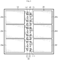
- FIGS. 1 to 4 A structure of a battery module according to an embodiment of the present disclosure will be described with reference to FIGS. 1 to 4 .
- FIG. 1 is a plane view showing a battery module according to an embodiment of the present disclosure
- FIGS. 2 and 3 are diagrams showing a coupling pattern of an electrode lead and a single support of a socket employed at the battery module according to an embodiment of the present disclosure
- FIG. 4 is a diagram showing a connecting bar employed at the battery module according to an embodiment of the present disclosure.
- the battery module includes a base plate 10, a plurality of battery cells 20, a plurality of sockets 30 and a plurality of connecting bars 40.
- the base plate 10 is a plate made of a non-conductive material and supports and/or fixes the battery cells 20 and the sockets 30.
- Any battery cell may be employed as the battery cell 20 of the present disclosure without limitation as long as a pair of electrode leads 21, 22 are drawn therefrom in the same direction.
- the battery cell 20 is provided in plural, and the plurality of battery cells 20 are placed on the base plate 10 and may be fixed by an adhesive or a fixing structure not to move.
- the plurality of battery cells 20 may be arranged to form two rows. That is, the plurality of battery cells 20 may be arranged to form a n ⁇ 2 matrix (n ⁇ 2, where n is a natural number), and the figures of the present disclosure depict a case where the plurality of battery cells 20 form a 3 ⁇ 2 matrix as an example.
- first battery cell 20a a first battery cell 20a
- second battery cell 20b a second battery cell 20b
- third battery cell 20c a fourth battery cell 20d
- fifth battery cell 20e a sixth battery cell 20f.
- the electrode leads 21, 22 of the battery cells 20a, 20c, 20e arranged in the first row and the electrode leads 21, 22 of the battery cells 20b, 20d, 20f arranged in the second row extend in opposite directions.
- the electrode leads 21, 22 of the battery cells 20a, 20c, 20e arranged in the first row and the electrode leads 21, 22 of the battery cells 20b, 20d, 20f arranged in the second row are disposed alternately in the vertical direction (the vertical direction means an upward and downward direction, based on FIG. 1 ).
- first electrode leads 21, 22 provided at the pair of battery cells 20 arranged in the same column are disposed in the order of the electrode lead 21 having a first polarity / the electrode lead 21 having the first polarity / the electrode lead 22 having a second polarity / the electrode lead 22 having the second polarity, from an upper side to a lower side (defined based on FIG. 1 ).
- the figures of the present disclosure depict only a case where the first electrode lead 21 having the first polarity is a positive electrode lead and the second electrode lead 22 having the second polarity is a negative electrode lead. However, the present disclosure is not limited thereto, and it is also possible that the first polarity is a negative polarity and the second polarity is a positive polarity, opposite to the above.
- the socket 30 is installed on the base plate 10 and connected to the electrode leads 21, 22 directly or indirectly, and includes a first support 31 connected to the electrode leads 21, 22 of the battery cells 20a, 20c, 20e arranged in the first row and a second support 32 connected to the electrode leads 21, 22 of the battery cells 20b, 20d, 20f arranged in the second row.
- the first support 31 and the second support 32 are spaced apart from each other, and thus the battery cells 20 are not electrically connected to each other in a state where the first support 31 and the second support 32 are not connected by the connecting bar 40.
- Two supports 31, 32 are connected to each of the electrode leads 21, 22, except for a pair of electrode leads 21, 22 located at the outermost periphery. That is, a pair of supports 31, 32 are disposed at one side and the other side of each of the electrode leads 21, 22 in the width direction, except for the pair of electrode leads 21, 22 located at the outermost periphery.
- the supports 31, 32 include a pair of sidewalls 31a and a connection portion 31b for connecting lower ends of the pair of sidewalls 31a.
- the connecting bar 40 explained later, is inserted into the space surrounded by the pair of sidewalls 31a and the connection portion 31b.
- a fixing rib 31c having a protruding shape may be provided on the sidewall 31b.
- FIG. 2 depicts only a case where the electrode leads 21, 22 make electric connection by coming into contact with the lower end of the connection portion 31b.
- the electrode leads 21, 22 make electric connection by coming into contact with the sidewall 31a.
- the supports 31, 32 and the electrode leads 21, 22 may be electrically connected to each other by direct contact, and also the supports 31, 32 and the electrode leads 21, 22 may be electrically connected in an indirect way by using a conductive pad 11 made of a conductive material and provided on the base plate 10.
- the connecting bar 40 is made of a conductive material, and one side of the connecting bar 40 is inserted into the first support 31 and the other side of the connecting bar 40 is inserted into the second support 32 to electrically connect the first support 31 and the second support 32, thereby electrically connecting the battery cells 20a, 20b arranged in the same column and facing each other.
- the connecting bar 40 is inserted into a part of the plurality of sockets 30 installed on the base plate 10 to connect the plurality of battery cells 20 in a combined serial and parallel connection pattern.
- the connecting bar 40 may have a pair of flange portions 41 provided at both ends thereof, and an insert portion 42 configured to connect the pair of flange portions 41 and inserted into the supports 31, 32.
- the flange portion 41 has a width greater than the width of an inner insertion space of the supports 31, 32, and the insert portion 42 has a width corresponding to the width of the inner insertion space of the supports 31, 32.
- one side of the insert portion 42 is inserted into the inner insertion space of the first support 31 and the other side of the insert portion 42 is inserted into the inner insertion space of the second support 32 to electrically connect the first support 31 and the second support 32.
- the flange portion 41 fixes the connecting bar 40 so that the connecting bar 40 does not move along the horizontal direction (parallel to the base plate 10).
- FIG. 5 is a diagram showing a case where a plurality of battery cells are connected to each other in a combined serial and parallel pattern (3S2P pattern) in the battery module according to an embodiment of the present disclosure
- FIG. 6 is a diagram showing a case where a plurality of battery cells are connected to each other in a serial pattern (6S pattern) in the battery module according to an embodiment of the present disclosure.
- the connecting bar 40 into a part of the plurality of sockets 30 electrically connected to the electrode leads 21, 22, it is possible to form a parallel connection between the battery cells arranged in the same column and to form a serial connection the battery cells arranged in different columns.
- the connecting bar 40 is inserted into the socket 30 disposed between the first electrode lead 21 of the first battery cell 20a and the first electrode lead 21 of the second battery cell 20b, among the battery cells 20a, 20b located in the first column, and is also inserted into the socket 30 disposed between the second electrode lead 22 of the first battery cell 20a and the second electrode lead 22 of the second battery cell 20b, among the battery cells 20a, 20b located in the first column. That is, the first battery cell 20a and the second battery cell 20b have a parallel connection relation since the electrode leads having the same polarity are electrically connected to each other.
- the first electrode lead 21 refers to an electrode lead having the first polarity
- the second electrode lead 22 refers to an electrode lead having the second polarity, as described above.
- the pair of battery cells 20c, 20d located in the second column and the pair of battery cells 20e, 20f located in the third column are also connected in parallel, similar to the first column.
- the connecting bar 40 is installed to connect battery cells located in different columns in series.
- the connecting bar 40 is inserted into the socket 30 located between the second electrode lead 22 of the second battery cell 20b located at the first column and the first electrode lead 21 of the first battery cell 20c located at the second column, thereby forming a serial connection relation between the battery cells 20a, 20b disposed in the first column and the battery cells 20c, 20d disposed in the second column.
- the serial connection relation is also applied between the battery cells 20c, 20d disposed in the second column and the battery cells 20e, 20f disposed in the third column.
- the battery module according to the present disclosure may have a desired electric connection relation by inserting the connecting bar 40 into a part of the sockets 30 arranged on the base plate 10, for example a combined serial and parallel connection pattern (3S2P) as shown in FIG. 5 .
- 3S2P combined serial and parallel connection pattern
- all battery cells 20a to 20f may be connected in series by inserting the connecting bar 40 into a part of the plurality of sockets 30 electrically connected to the electrode leads 21, 22.
- the connecting bar 40 is inserted into the socket disposed between the second electrode lead 22 of the first battery cell 20a and the first electrode lead 21 of the second battery cell 20b, among the battery cells 20a, 20b located in the first column. That is, the first battery cell 20a and the second battery cell 20b have a serial connection relation as electrode leads having different polarities are connected.
- the pair of battery cells 20c, 20d located in the second column and the pair of battery cells 20e, 20f located in the third column are connected in series, similar to the first column.
- connecting bar 40 is installed so that battery cells located in different columns are also connected in series.
- the connecting bar 40 is inserted into the socket 30 disposed between the second electrode lead 22 of the second battery cell 20b located in the first column and the first electrode lead 21 of the first battery cell 20c located in the second column, thereby forming a serial connection relation also between the battery cells 20a, 20b disposed in the first column and the battery cells 20c, 20d disposed in the second column.
- the serial connection relation is also applied between the battery cells 20c, 20d disposed in the second column and the battery cells 20e, 20f disposed in the third column.
- the battery module according to the present disclosure may have a desired electric connection relation by inserting the connecting bar 40 into a part of the sockets 30 disposed on the base plate 10. Also, depending on the selected installation position of the connecting bar 40, it is possible to have a combined serial and parallel connection relation as shown in FIG. 5 or a serial connection relation (6S) as shown in FIG. 6 .
- the battery module according to the present disclosure may selectively have a serial connection pattern where all battery cells 20 are connected in series or a combined serial and parallel connection pattern by inserting the connecting bar 40 into a part of the plurality of sockets 30 as desired by the user, due to the arrangement relationship of the plurality of battery cells 20 and the sockets 30 installed on the base plate 10.
- a user may install the connecting bar 40 so that all the battery cells 20 are connected in series in a situation where a high voltage is required, and or may install the connecting bar 40 so that the battery cells 20 are connected in a combined serial and parallel pattern when a large capacity is required than a high voltage.
Landscapes
- Chemical & Material Sciences (AREA)
- Chemical Kinetics & Catalysis (AREA)
- Electrochemistry (AREA)
- General Chemical & Material Sciences (AREA)
- Engineering & Computer Science (AREA)
- Manufacturing & Machinery (AREA)
- Connection Of Batteries Or Terminals (AREA)
- Battery Mounting, Suspending (AREA)
Abstract
Description
- The present disclosure relates to a battery module, and more particularly, to a battery module having a structure capable of easily changing a connection pattern among a plurality of battery cells.
- The present application claims priority to Korean Patent Application No.
10-2017-0128194 filed on September 29, 2017 - Recently, along with the technology development of electric devices and electric vehicle, it is demanded to increase the capacity of a secondary battery, and also a larger output voltage is required. Thus, in order to obtain a sufficient output voltage by using the secondary battery, a plurality of secondary batteries may be connected in series.
- However, if a plurality of secondary batteries are connected in series and used for a long time, the voltages of the secondary batteries may be different from each other. In addition, it may be more important to increase the total capacity of the secondary batteries than to increase the output voltage of the secondary batteries. If it is demanded to increase the overall capacity of the secondary batteries, a plurality of secondary batteries need to be connected in parallel.
- As described above, a plurality of secondary batteries may be connected in series, in parallel, or a combination thereof, depending on the usage situation. In general, the electrical connection pattern of the plurality of secondary batteries is determined in the manufacturing process. In this case, even though there is a necessity to change the connection pattern during the use, it is not possible to change the connection pattern.
- The present disclosure is designed to solve the problems of the related art, and therefore the present disclosure is directed to providing a battery module, which includes a plurality of battery cells and has a structure in which a user may freely change an electrical connection pattern of the plurality of battery cells, namely into a serial connection, a parallel connection, or a combination thereof.
- However, the technical problem to be solved by the present disclosure is not limited to the above, and other objects not mentioned herein will be understood from the following description by those skilled in the art.
- In one aspect of the present disclosure, there is provided a battery module, comprising: a base plate; a plurality of battery cells disposed on the base plate; a plurality of sockets electrically connected to electrode leads of the battery cells; and a plurality of connecting bars inserted into a part of the plurality of sockets so that the plurality of battery cells are connected in a combined serial and parallel pattern.
- The base plate may include a plurality of conductive pads, and the socket may be electrically connected to the electrode lead through the conductive pad.
- The plurality of battery cells may be arranged to form two rows.
- In case of a pair of battery cells arranged in the same column, electrode leads of the battery cell arranged in the first row and electrode leads of the battery cell arranged in the second row may extend in opposite directions.
- The electrode leads of the battery cell arranged in the first row and the electrode leads of the battery cell arranged in the second row may be disposed alternately.
- The socket may include a first support electrically connected to the electrode leads of the battery cell arranged in the first row; and a second support electrically connected to the electrode leads of the battery cell arranged in the second row and electrically insulating from the first support.
- The first support and the second support may respectively include a pair of sidewalls; and a connection portion configured to connect lower ends of the pair of sidewalls.
- The connecting bar may be inserted between the pair of sidewalls of both the first support and the second support to electrically connect the first support and the second support.
- The connecting bar may include a pair of flange portions formed at both side ends thereof to limit a horizontal movement of the connecting bar; and an insert portion configured to connect the pair of flange portions and inserted between the pair of sidewalls.
- The insert portion may have a width corresponding to a length between the pair of sidewalls.
- According to the present disclosure, in the battery module including a plurality of battery cells, a user may freely change an electrical connection pattern of the plurality of battery cells, namely into a serial connection, a parallel connection, or a combination thereof.
- The accompanying drawings illustrate a preferred embodiment of the present disclosure and together with the foregoing disclosure, serve to provide further understanding of the technical features of the present disclosure, and thus, the present disclosure is not construed as being limited to the drawing.
-
FIG. 1 is a plane view showing a battery module according to an embodiment of the present disclosure. -
FIGS. 2 and3 are diagrams showing a coupling pattern of an electrode lead and a single support of a socket employed at the battery module according to an embodiment of the present disclosure. -
FIG. 4 is a diagram showing a connecting bar employed at the battery module according to an embodiment of the present disclosure. -
FIG. 5 is a diagram showing a case where a plurality of battery cells are connected to each other in a combined serial and parallel pattern (3S2P pattern) in the battery module according to an embodiment of the present disclosure. -
FIG. 6 is a diagram showing a case where a plurality of battery cells are connected to each other in a serial pattern (6S pattern) in the battery module according to an embodiment of the present disclosure. - Hereinafter, preferred embodiments of the present disclosure will be described in detail with reference to the accompanying drawings. Prior to the description, it should be understood that the terms used in the specification and the appended claims should not be construed as limited to general and dictionary meanings, but interpreted based on the meanings and concepts corresponding to technical aspects of the present disclosure on the basis of the principle that the inventor is allowed to define terms appropriately for the best explanation. Therefore, the description proposed herein is just a preferable example for the purpose of illustrations only, not intended to limit the scope of the disclosure, so it should be understood that other equivalents and modifications could be made thereto without departing from the scope of the disclosure.
- A structure of a battery module according to an embodiment of the present disclosure will be described with reference to
FIGS. 1 to 4 . -
FIG. 1 is a plane view showing a battery module according to an embodiment of the present disclosure,FIGS. 2 and3 are diagrams showing a coupling pattern of an electrode lead and a single support of a socket employed at the battery module according to an embodiment of the present disclosure, andFIG. 4 is a diagram showing a connecting bar employed at the battery module according to an embodiment of the present disclosure. - First, referring to
FIG. 1 , the battery module according to an embodiment of the present disclosure includes abase plate 10, a plurality ofbattery cells 20, a plurality ofsockets 30 and a plurality of connectingbars 40. - The
base plate 10 is a plate made of a non-conductive material and supports and/or fixes thebattery cells 20 and thesockets 30. - Any battery cell may be employed as the
battery cell 20 of the present disclosure without limitation as long as a pair of electrode leads 21, 22 are drawn therefrom in the same direction. Thebattery cell 20 is provided in plural, and the plurality ofbattery cells 20 are placed on thebase plate 10 and may be fixed by an adhesive or a fixing structure not to move. - The plurality of
battery cells 20 may be arranged to form two rows. That is, the plurality ofbattery cells 20 may be arranged to form a n×2 matrix (n ≥ 2, where n is a natural number), and the figures of the present disclosure depict a case where the plurality ofbattery cells 20 form a 3×2 matrix as an example. - For the convenience of explanation, in the present disclosure, six battery cells shown in the figures will be differently referred to as a
first battery cell 20a, asecond battery cell 20b, athird battery cell 20c, afourth battery cell 20d, afifth battery cell 20e and asixth battery cell 20f. - In a pair of
battery cells 20 arranged in the same column, the electrode leads 21, 22 of thebattery cells battery cells battery cells battery cells FIG. 1 ). - Meanwhile, four electrode leads 21, 22 provided at the pair of
battery cells 20 arranged in the same column are disposed in the order of theelectrode lead 21 having a first polarity / theelectrode lead 21 having the first polarity / theelectrode lead 22 having a second polarity / theelectrode lead 22 having the second polarity, from an upper side to a lower side (defined based onFIG. 1 ). The figures of the present disclosure depict only a case where the first electrode lead 21 having the first polarity is a positive electrode lead and thesecond electrode lead 22 having the second polarity is a negative electrode lead. However, the present disclosure is not limited thereto, and it is also possible that the first polarity is a negative polarity and the second polarity is a positive polarity, opposite to the above. - The
socket 30 is installed on thebase plate 10 and connected to the electrode leads 21, 22 directly or indirectly, and includes afirst support 31 connected to the electrode leads 21, 22 of thebattery cells second support 32 connected to the electrode leads 21, 22 of thebattery cells - The
first support 31 and thesecond support 32 are spaced apart from each other, and thus thebattery cells 20 are not electrically connected to each other in a state where thefirst support 31 and thesecond support 32 are not connected by the connectingbar 40. - Two
supports supports - Referring to
FIG. 2 , the supports 31, 32 include a pair ofsidewalls 31a and aconnection portion 31b for connecting lower ends of the pair ofsidewalls 31a. The connectingbar 40, explained later, is inserted into the space surrounded by the pair ofsidewalls 31a and theconnection portion 31b. In order to stably fix the connectingbar 40 when being inserted, afixing rib 31c having a protruding shape may be provided on thesidewall 31b. - Meanwhile, even though
FIG. 2 depicts only a case where the electrode leads 21, 22 make electric connection by coming into contact with the lower end of theconnection portion 31b. However, unlike this, it is also possible that the electrode leads 21, 22 make electric connection by coming into contact with thesidewall 31a. In addition, as shown inFIG. 3 , the supports 31, 32 and the electrode leads 21, 22 may be electrically connected to each other by direct contact, and also thesupports conductive pad 11 made of a conductive material and provided on thebase plate 10. - Referring to
FIG. 4 along withFIG. 1 , the connectingbar 40 is made of a conductive material, and one side of the connectingbar 40 is inserted into thefirst support 31 and the other side of the connectingbar 40 is inserted into thesecond support 32 to electrically connect thefirst support 31 and thesecond support 32, thereby electrically connecting thebattery cells - The connecting
bar 40 is inserted into a part of the plurality ofsockets 30 installed on thebase plate 10 to connect the plurality ofbattery cells 20 in a combined serial and parallel connection pattern. - As shown in
FIG. 4 , the connectingbar 40 may have a pair offlange portions 41 provided at both ends thereof, and aninsert portion 42 configured to connect the pair offlange portions 41 and inserted into thesupports - Referring to
FIGS. 1 and2 along withFIG. 4 , theflange portion 41 has a width greater than the width of an inner insertion space of thesupports insert portion 42 has a width corresponding to the width of the inner insertion space of thesupports - That is, one side of the
insert portion 42 is inserted into the inner insertion space of thefirst support 31 and the other side of theinsert portion 42 is inserted into the inner insertion space of thesecond support 32 to electrically connect thefirst support 31 and thesecond support 32. At this time, theflange portion 41 fixes the connectingbar 40 so that the connectingbar 40 does not move along the horizontal direction (parallel to the base plate 10). - Next, an electric connection pattern of the battery module according to an embodiment of the present disclosure will be described with reference to
FIGS. 5 and6 . -
FIG. 5 is a diagram showing a case where a plurality of battery cells are connected to each other in a combined serial and parallel pattern (3S2P pattern) in the battery module according to an embodiment of the present disclosure, andFIG. 6 is a diagram showing a case where a plurality of battery cells are connected to each other in a serial pattern (6S pattern) in the battery module according to an embodiment of the present disclosure. - First, referring to
FIG. 5 , in the battery module according to an embodiment of the present disclosure, by inserting the connectingbar 40 into a part of the plurality ofsockets 30 electrically connected to the electrode leads 21, 22, it is possible to form a parallel connection between the battery cells arranged in the same column and to form a serial connection the battery cells arranged in different columns. - In this case, the connecting
bar 40 is inserted into thesocket 30 disposed between thefirst electrode lead 21 of thefirst battery cell 20a and thefirst electrode lead 21 of thesecond battery cell 20b, among thebattery cells socket 30 disposed between thesecond electrode lead 22 of thefirst battery cell 20a and thesecond electrode lead 22 of thesecond battery cell 20b, among thebattery cells first battery cell 20a and thesecond battery cell 20b have a parallel connection relation since the electrode leads having the same polarity are electrically connected to each other. - Here, the
first electrode lead 21 refers to an electrode lead having the first polarity, and thesecond electrode lead 22 refers to an electrode lead having the second polarity, as described above. - Meanwhile, the pair of
battery cells battery cells - Also, the connecting
bar 40 is installed to connect battery cells located in different columns in series. - For example, the connecting
bar 40 is inserted into thesocket 30 located between thesecond electrode lead 22 of thesecond battery cell 20b located at the first column and thefirst electrode lead 21 of thefirst battery cell 20c located at the second column, thereby forming a serial connection relation between thebattery cells battery cells - The serial connection relation is also applied between the
battery cells battery cells - As described above, the battery module according to the present disclosure may have a desired electric connection relation by inserting the connecting
bar 40 into a part of thesockets 30 arranged on thebase plate 10, for example a combined serial and parallel connection pattern (3S2P) as shown inFIG. 5 . - Next, referring to
FIG. 6 , in the battery module according to an embodiment of the present disclosure, allbattery cells 20a to 20f may be connected in series by inserting the connectingbar 40 into a part of the plurality ofsockets 30 electrically connected to the electrode leads 21, 22. - In this case, the connecting
bar 40 is inserted into the socket disposed between thesecond electrode lead 22 of thefirst battery cell 20a and thefirst electrode lead 21 of thesecond battery cell 20b, among thebattery cells first battery cell 20a and thesecond battery cell 20b have a serial connection relation as electrode leads having different polarities are connected. - Meanwhile, the pair of
battery cells battery cells - In addition, the connecting
bar 40 is installed so that battery cells located in different columns are also connected in series. - For example, the connecting
bar 40 is inserted into thesocket 30 disposed between thesecond electrode lead 22 of thesecond battery cell 20b located in the first column and thefirst electrode lead 21 of thefirst battery cell 20c located in the second column, thereby forming a serial connection relation also between thebattery cells battery cells - The serial connection relation is also applied between the
battery cells battery cells - As described above, the battery module according to the present disclosure may have a desired electric connection relation by inserting the connecting
bar 40 into a part of thesockets 30 disposed on thebase plate 10. Also, depending on the selected installation position of the connectingbar 40, it is possible to have a combined serial and parallel connection relation as shown inFIG. 5 or a serial connection relation (6S) as shown inFIG. 6 . - As described above, the battery module according to the present disclosure may selectively have a serial connection pattern where all
battery cells 20 are connected in series or a combined serial and parallel connection pattern by inserting the connectingbar 40 into a part of the plurality ofsockets 30 as desired by the user, due to the arrangement relationship of the plurality ofbattery cells 20 and thesockets 30 installed on thebase plate 10. - That is, a user may install the connecting
bar 40 so that all thebattery cells 20 are connected in series in a situation where a high voltage is required, and or may install the connectingbar 40 so that thebattery cells 20 are connected in a combined serial and parallel pattern when a large capacity is required than a high voltage. - The present disclosure has been described in detail. However, it should be understood that the detailed description and specific examples, while indicating preferred embodiments of the disclosure, are given by way of illustration only, since various changes and modifications within the scope of the disclosure will become apparent to those skilled in the art from this detailed description.
Claims (10)
- A battery module, comprising:a base plate;a plurality of battery cells disposed on the base plate;a plurality of sockets electrically connected to electrode leads of the battery cells; anda plurality of connecting bars inserted into a part of the plurality of sockets so that the plurality of battery cells are connected in a combined serial and parallel pattern.
- The battery module according to claim 1,
wherein the base plate includes a plurality of conductive pads, and
wherein the socket is electrically connected to the electrode lead through the conductive pad. - The battery module according to claim 1,
wherein the plurality of battery cells are arranged to form two rows. - The battery module according to claim 3,
wherein in case of a pair of battery cells arranged in the same column, electrode leads of the battery cell arranged in the first row and electrode leads of the battery cell arranged in the second row extend in opposite directions. - The battery module according to claim 4,
wherein the electrode leads of the battery cell arranged in the first row and the electrode leads of the battery cell arranged in the second row are disposed alternately. - The battery module according to claim 3,
wherein the socket includes:a first support electrically connected to the electrode leads of the battery cell arranged in the first row; anda second support electrically connected to the electrode leads of the battery cell arranged in the second row and electrically insulating from the first support. - The battery module according to claim 6,
wherein the first support and the second support respectively include:a pair of sidewalls; anda connection portion configured to connect lower ends of the pair of sidewalls. - The battery module according to claim 7,
wherein the connecting bar is inserted between the pair of sidewalls of both the first support and the second support to electrically connect the first support and the second support. - The battery module according to claim 7,
wherein the connecting bar includes:a pair of flange portions formed at both side ends thereof to limit a horizontal movement of the connecting bar; andan insert portion configured to connect the pair of flange portions and inserted between the pair of sidewalls. - The battery module according to claim 9,
wherein the insert portion has a width corresponding to a length between the pair of sidewalls.
Applications Claiming Priority (2)
| Application Number | Priority Date | Filing Date | Title |
|---|---|---|---|
| KR1020170128194A KR102259969B1 (en) | 2017-09-29 | 2017-09-29 | Battery module |
| PCT/KR2018/007592 WO2019066213A1 (en) | 2017-09-29 | 2018-07-04 | Battery module |
Publications (3)
| Publication Number | Publication Date |
|---|---|
| EP3595041A1 true EP3595041A1 (en) | 2020-01-15 |
| EP3595041A4 EP3595041A4 (en) | 2020-06-24 |
| EP3595041B1 EP3595041B1 (en) | 2023-09-06 |
Family
ID=65903031
Family Applications (1)
| Application Number | Title | Priority Date | Filing Date |
|---|---|---|---|
| EP18861097.6A Active EP3595041B1 (en) | 2017-09-29 | 2018-07-04 | Battery module |
Country Status (9)
| Country | Link |
|---|---|
| US (1) | US11031659B2 (en) |
| EP (1) | EP3595041B1 (en) |
| JP (1) | JP6749500B2 (en) |
| KR (1) | KR102259969B1 (en) |
| CN (1) | CN110168776B (en) |
| ES (1) | ES2955571T3 (en) |
| HU (1) | HUE062983T2 (en) |
| PL (1) | PL3595041T3 (en) |
| WO (1) | WO2019066213A1 (en) |
Family Cites Families (21)
| Publication number | Priority date | Publication date | Assignee | Title |
|---|---|---|---|---|
| JPH09147826A (en) | 1995-11-24 | 1997-06-06 | Aqueous Res:Kk | Connection switching device for power storage means |
| JP5242131B2 (en) * | 2007-10-31 | 2013-07-24 | 矢崎総業株式会社 | Power supply |
| KR100949333B1 (en) * | 2007-11-12 | 2010-03-26 | 삼성에스디아이 주식회사 | Battery module |
| JP2009231138A (en) * | 2008-03-24 | 2009-10-08 | Toshiba Corp | Battery pack |
| JP5146092B2 (en) * | 2008-05-09 | 2013-02-20 | 株式会社Gsユアサ | Battery assembly spacer and battery assembly using the same |
| JP5309696B2 (en) * | 2008-05-29 | 2013-10-09 | 株式会社Gsユアサ | Assembled battery |
| JP2010009796A (en) | 2008-06-25 | 2010-01-14 | Nec Tokin Corp | Secondary battery pack |
| DE102008059970B4 (en) * | 2008-12-02 | 2013-11-07 | Daimler Ag | Battery, in particular vehicle battery |
| CN102110798B (en) * | 2009-12-28 | 2015-04-08 | 三星Sdi株式会社 | Battery module |
| US9716258B2 (en) * | 2011-04-26 | 2017-07-25 | Samsung Sdi Co., Ltd. | Battery pack |
| JP5145452B1 (en) * | 2011-09-16 | 2013-02-20 | 日本航空電子工業株式会社 | Power storage device |
| KR101347211B1 (en) | 2012-05-29 | 2014-01-10 | 주식회사 아이티엠반도체 | Battery system for controling of parallel or serial connection |
| JP2014154245A (en) * | 2013-02-05 | 2014-08-25 | Yazaki Corp | Connection connector and connection structure between cell and electrode of cell module |
| JP2014176152A (en) | 2013-03-07 | 2014-09-22 | Tdk Corp | Power storage system |
| KR101550790B1 (en) | 2013-07-29 | 2015-09-09 | 주식회사 이랜텍 | Connecting member for electrode of battery cell |
| CN104752667B (en) | 2013-12-31 | 2018-02-09 | 比亚迪股份有限公司 | Power battery module |
| JP5929937B2 (en) * | 2014-01-30 | 2016-06-08 | トヨタ自動車株式会社 | Battery pack and battery connection switching method |
| US20160093854A1 (en) * | 2014-09-26 | 2016-03-31 | Johnson Controls Technology Company | Prismatic battery cell energy density for a lithium ion battery module |
| KR20170077467A (en) * | 2015-12-28 | 2017-07-06 | 한국단자공업 주식회사 | Series connection apparatus of battery module |
| CN205406622U (en) * | 2016-03-11 | 2016-07-27 | 宁德时代新能源科技股份有限公司 | Battery module |
| KR101964300B1 (en) | 2017-11-14 | 2019-04-01 | 한국과학기술연구원 | Apparatus and method for implementing motion of robot using knowledge model |
-
2017
- 2017-09-29 KR KR1020170128194A patent/KR102259969B1/en active Active
-
2018
- 2018-07-04 CN CN201880006587.3A patent/CN110168776B/en active Active
- 2018-07-04 JP JP2019540410A patent/JP6749500B2/en active Active
- 2018-07-04 US US16/478,656 patent/US11031659B2/en active Active
- 2018-07-04 ES ES18861097T patent/ES2955571T3/en active Active
- 2018-07-04 WO PCT/KR2018/007592 patent/WO2019066213A1/en not_active Ceased
- 2018-07-04 PL PL18861097.6T patent/PL3595041T3/en unknown
- 2018-07-04 HU HUE18861097A patent/HUE062983T2/en unknown
- 2018-07-04 EP EP18861097.6A patent/EP3595041B1/en active Active
Also Published As
| Publication number | Publication date |
|---|---|
| WO2019066213A1 (en) | 2019-04-04 |
| ES2955571T3 (en) | 2023-12-04 |
| JP2020514993A (en) | 2020-05-21 |
| CN110168776A (en) | 2019-08-23 |
| US20190372080A1 (en) | 2019-12-05 |
| KR20190038127A (en) | 2019-04-08 |
| EP3595041B1 (en) | 2023-09-06 |
| US11031659B2 (en) | 2021-06-08 |
| EP3595041A4 (en) | 2020-06-24 |
| JP6749500B2 (en) | 2020-09-02 |
| HUE062983T2 (en) | 2023-12-28 |
| PL3595041T3 (en) | 2023-12-04 |
| KR102259969B1 (en) | 2021-06-02 |
| CN110168776B (en) | 2022-03-15 |
Similar Documents
| Publication | Publication Date | Title |
|---|---|---|
| KR101299139B1 (en) | Battery Cell Holder of Improved Connecting Reliability and Battery Module Employed with the Same | |
| KR102163683B1 (en) | Battery cell formation device and probe supporting structure thereof | |
| EP2390945B1 (en) | Battery module | |
| US20210203029A1 (en) | Battery pack | |
| KR102395752B1 (en) | Battery pack | |
| US10770709B2 (en) | Connection module | |
| KR101795718B1 (en) | Extendible Battery Cell Module Assembly | |
| US8293392B2 (en) | Battery holder for a battery array, and battery array | |
| KR20100096755A (en) | Battery module | |
| US9184472B2 (en) | Battery pack and method of manufacturing battery pack with interconnected half contact pads | |
| US20160072113A1 (en) | Bus bar module and power supply device | |
| CN110476269B (en) | Cap assembly for accommodating a plurality of secondary battery cells and battery module including the same | |
| US10270080B2 (en) | Battery pack | |
| CN106935780A (en) | Battery module and battery pack | |
| EP3035412B1 (en) | Battery module and battery cell | |
| JP6741215B2 (en) | Connection module | |
| KR20180010591A (en) | Battery pack | |
| CN114730968B (en) | Battery module provided with track-type socket and battery pack including the battery module | |
| EP3032614B1 (en) | Battery module and battery cell | |
| EP3595041B1 (en) | Battery module | |
| KR101084829B1 (en) | Battery pack | |
| KR20140005521A (en) | Battery cell and battery module using the same | |
| CN201498848U (en) | LED socket connector | |
| CN112332031A (en) | Connecting element for electrical contacting and method for producing a connecting element | |
| CN110707251A (en) | Annular heat dissipation lithium cell package subassembly |
Legal Events
| Date | Code | Title | Description |
|---|---|---|---|
| STAA | Information on the status of an ep patent application or granted ep patent |
Free format text: STATUS: THE INTERNATIONAL PUBLICATION HAS BEEN MADE |
|
| PUAI | Public reference made under article 153(3) epc to a published international application that has entered the european phase |
Free format text: ORIGINAL CODE: 0009012 |
|
| STAA | Information on the status of an ep patent application or granted ep patent |
Free format text: STATUS: REQUEST FOR EXAMINATION WAS MADE |
|
| 17P | Request for examination filed |
Effective date: 20191011 |
|
| AK | Designated contracting states |
Kind code of ref document: A1 Designated state(s): AL AT BE BG CH CY CZ DE DK EE ES FI FR GB GR HR HU IE IS IT LI LT LU LV MC MK MT NL NO PL PT RO RS SE SI SK SM TR |
|
| AX | Request for extension of the european patent |
Extension state: BA ME |
|
| A4 | Supplementary search report drawn up and despatched |
Effective date: 20200527 |
|
| RIC1 | Information provided on ipc code assigned before grant |
Ipc: H01M 2/20 20060101AFI20200519BHEP Ipc: H01M 2/26 20060101ALI20200519BHEP Ipc: H01M 2/10 20060101ALI20200519BHEP |
|
| DAV | Request for validation of the european patent (deleted) | ||
| DAX | Request for extension of the european patent (deleted) | ||
| RAP1 | Party data changed (applicant data changed or rights of an application transferred) |
Owner name: LG ENERGY SOLUTION LTD. |
|
| RAP3 | Party data changed (applicant data changed or rights of an application transferred) |
Owner name: LG ENERGY SOLUTION, LTD. |
|
| REG | Reference to a national code |
Ref country code: DE Ref legal event code: R079 Free format text: PREVIOUS MAIN CLASS: H01M0002200000 Ipc: H01M0050209000 Ref document number: 602018057191 Country of ref document: DE |
|
| GRAP | Despatch of communication of intention to grant a patent |
Free format text: ORIGINAL CODE: EPIDOSNIGR1 |
|
| STAA | Information on the status of an ep patent application or granted ep patent |
Free format text: STATUS: GRANT OF PATENT IS INTENDED |
|
| RIC1 | Information provided on ipc code assigned before grant |
Ipc: H01M 50/51 20210101ALI20230329BHEP Ipc: H01M 50/509 20210101ALI20230329BHEP Ipc: H01M 50/507 20210101ALI20230329BHEP Ipc: H01M 50/503 20210101ALI20230329BHEP Ipc: H01M 50/209 20210101AFI20230329BHEP |
|
| INTG | Intention to grant announced |
Effective date: 20230417 |
|
| P01 | Opt-out of the competence of the unified patent court (upc) registered |
Effective date: 20230516 |
|
| GRAS | Grant fee paid |
Free format text: ORIGINAL CODE: EPIDOSNIGR3 |
|
| GRAA | (expected) grant |
Free format text: ORIGINAL CODE: 0009210 |
|
| STAA | Information on the status of an ep patent application or granted ep patent |
Free format text: STATUS: THE PATENT HAS BEEN GRANTED |
|
| AK | Designated contracting states |
Kind code of ref document: B1 Designated state(s): AL AT BE BG CH CY CZ DE DK EE ES FI FR GB GR HR HU IE IS IT LI LT LU LV MC MK MT NL NO PL PT RO RS SE SI SK SM TR |
|
| REG | Reference to a national code |
Ref country code: GB Ref legal event code: FG4D |
|
| REG | Reference to a national code |
Ref country code: CH Ref legal event code: EP |
|
| REG | Reference to a national code |
Ref country code: IE Ref legal event code: FG4D |
|
| REG | Reference to a national code |
Ref country code: DE Ref legal event code: R096 Ref document number: 602018057191 Country of ref document: DE |
|
| REG | Reference to a national code |
Ref country code: SE Ref legal event code: TRGR |
|
| REG | Reference to a national code |
Ref country code: ES Ref legal event code: FG2A Ref document number: 2955571 Country of ref document: ES Kind code of ref document: T3 Effective date: 20231204 |
|
| REG | Reference to a national code |
Ref country code: LT Ref legal event code: MG9D |
|
| REG | Reference to a national code |
Ref country code: HU Ref legal event code: AG4A Ref document number: E062983 Country of ref document: HU |
|
| REG | Reference to a national code |
Ref country code: NL Ref legal event code: MP Effective date: 20230906 |
|
| PG25 | Lapsed in a contracting state [announced via postgrant information from national office to epo] |
Ref country code: GR Free format text: LAPSE BECAUSE OF FAILURE TO SUBMIT A TRANSLATION OF THE DESCRIPTION OR TO PAY THE FEE WITHIN THE PRESCRIBED TIME-LIMIT Effective date: 20231207 |
|
| PG25 | Lapsed in a contracting state [announced via postgrant information from national office to epo] |
Ref country code: RS Free format text: LAPSE BECAUSE OF FAILURE TO SUBMIT A TRANSLATION OF THE DESCRIPTION OR TO PAY THE FEE WITHIN THE PRESCRIBED TIME-LIMIT Effective date: 20230906 Ref country code: NO Free format text: LAPSE BECAUSE OF FAILURE TO SUBMIT A TRANSLATION OF THE DESCRIPTION OR TO PAY THE FEE WITHIN THE PRESCRIBED TIME-LIMIT Effective date: 20231206 Ref country code: LV Free format text: LAPSE BECAUSE OF FAILURE TO SUBMIT A TRANSLATION OF THE DESCRIPTION OR TO PAY THE FEE WITHIN THE PRESCRIBED TIME-LIMIT Effective date: 20230906 Ref country code: LT Free format text: LAPSE BECAUSE OF FAILURE TO SUBMIT A TRANSLATION OF THE DESCRIPTION OR TO PAY THE FEE WITHIN THE PRESCRIBED TIME-LIMIT Effective date: 20230906 Ref country code: HR Free format text: LAPSE BECAUSE OF FAILURE TO SUBMIT A TRANSLATION OF THE DESCRIPTION OR TO PAY THE FEE WITHIN THE PRESCRIBED TIME-LIMIT Effective date: 20230906 Ref country code: GR Free format text: LAPSE BECAUSE OF FAILURE TO SUBMIT A TRANSLATION OF THE DESCRIPTION OR TO PAY THE FEE WITHIN THE PRESCRIBED TIME-LIMIT Effective date: 20231207 Ref country code: FI Free format text: LAPSE BECAUSE OF FAILURE TO SUBMIT A TRANSLATION OF THE DESCRIPTION OR TO PAY THE FEE WITHIN THE PRESCRIBED TIME-LIMIT Effective date: 20230906 |
|
| REG | Reference to a national code |
Ref country code: AT Ref legal event code: MK05 Ref document number: 1609747 Country of ref document: AT Kind code of ref document: T Effective date: 20230906 |
|
| PG25 | Lapsed in a contracting state [announced via postgrant information from national office to epo] |
Ref country code: NL Free format text: LAPSE BECAUSE OF FAILURE TO SUBMIT A TRANSLATION OF THE DESCRIPTION OR TO PAY THE FEE WITHIN THE PRESCRIBED TIME-LIMIT Effective date: 20230906 |
|
| PG25 | Lapsed in a contracting state [announced via postgrant information from national office to epo] |
Ref country code: IS Free format text: LAPSE BECAUSE OF FAILURE TO SUBMIT A TRANSLATION OF THE DESCRIPTION OR TO PAY THE FEE WITHIN THE PRESCRIBED TIME-LIMIT Effective date: 20240106 |
|
| PG25 | Lapsed in a contracting state [announced via postgrant information from national office to epo] |
Ref country code: AT Free format text: LAPSE BECAUSE OF FAILURE TO SUBMIT A TRANSLATION OF THE DESCRIPTION OR TO PAY THE FEE WITHIN THE PRESCRIBED TIME-LIMIT Effective date: 20230906 |
|
| PG25 | Lapsed in a contracting state [announced via postgrant information from national office to epo] |
Ref country code: SM Free format text: LAPSE BECAUSE OF FAILURE TO SUBMIT A TRANSLATION OF THE DESCRIPTION OR TO PAY THE FEE WITHIN THE PRESCRIBED TIME-LIMIT Effective date: 20230906 Ref country code: RO Free format text: LAPSE BECAUSE OF FAILURE TO SUBMIT A TRANSLATION OF THE DESCRIPTION OR TO PAY THE FEE WITHIN THE PRESCRIBED TIME-LIMIT Effective date: 20230906 Ref country code: IS Free format text: LAPSE BECAUSE OF FAILURE TO SUBMIT A TRANSLATION OF THE DESCRIPTION OR TO PAY THE FEE WITHIN THE PRESCRIBED TIME-LIMIT Effective date: 20240106 Ref country code: EE Free format text: LAPSE BECAUSE OF FAILURE TO SUBMIT A TRANSLATION OF THE DESCRIPTION OR TO PAY THE FEE WITHIN THE PRESCRIBED TIME-LIMIT Effective date: 20230906 Ref country code: CZ Free format text: LAPSE BECAUSE OF FAILURE TO SUBMIT A TRANSLATION OF THE DESCRIPTION OR TO PAY THE FEE WITHIN THE PRESCRIBED TIME-LIMIT Effective date: 20230906 Ref country code: AT Free format text: LAPSE BECAUSE OF FAILURE TO SUBMIT A TRANSLATION OF THE DESCRIPTION OR TO PAY THE FEE WITHIN THE PRESCRIBED TIME-LIMIT Effective date: 20230906 Ref country code: PT Free format text: LAPSE BECAUSE OF FAILURE TO SUBMIT A TRANSLATION OF THE DESCRIPTION OR TO PAY THE FEE WITHIN THE PRESCRIBED TIME-LIMIT Effective date: 20240108 Ref country code: SK Free format text: LAPSE BECAUSE OF FAILURE TO SUBMIT A TRANSLATION OF THE DESCRIPTION OR TO PAY THE FEE WITHIN THE PRESCRIBED TIME-LIMIT Effective date: 20230906 |
|
| PG25 | Lapsed in a contracting state [announced via postgrant information from national office to epo] |
Ref country code: IT Free format text: LAPSE BECAUSE OF FAILURE TO SUBMIT A TRANSLATION OF THE DESCRIPTION OR TO PAY THE FEE WITHIN THE PRESCRIBED TIME-LIMIT Effective date: 20230906 |
|
| REG | Reference to a national code |
Ref country code: DE Ref legal event code: R097 Ref document number: 602018057191 Country of ref document: DE |
|
| PG25 | Lapsed in a contracting state [announced via postgrant information from national office to epo] |
Ref country code: DK Free format text: LAPSE BECAUSE OF FAILURE TO SUBMIT A TRANSLATION OF THE DESCRIPTION OR TO PAY THE FEE WITHIN THE PRESCRIBED TIME-LIMIT Effective date: 20230906 |
|
| PLBE | No opposition filed within time limit |
Free format text: ORIGINAL CODE: 0009261 |
|
| STAA | Information on the status of an ep patent application or granted ep patent |
Free format text: STATUS: NO OPPOSITION FILED WITHIN TIME LIMIT |
|
| PG25 | Lapsed in a contracting state [announced via postgrant information from national office to epo] |
Ref country code: DK Free format text: LAPSE BECAUSE OF FAILURE TO SUBMIT A TRANSLATION OF THE DESCRIPTION OR TO PAY THE FEE WITHIN THE PRESCRIBED TIME-LIMIT Effective date: 20230906 Ref country code: SI Free format text: LAPSE BECAUSE OF FAILURE TO SUBMIT A TRANSLATION OF THE DESCRIPTION OR TO PAY THE FEE WITHIN THE PRESCRIBED TIME-LIMIT Effective date: 20230906 |
|
| 26N | No opposition filed |
Effective date: 20240607 |
|
| PG25 | Lapsed in a contracting state [announced via postgrant information from national office to epo] |
Ref country code: BG Free format text: LAPSE BECAUSE OF FAILURE TO SUBMIT A TRANSLATION OF THE DESCRIPTION OR TO PAY THE FEE WITHIN THE PRESCRIBED TIME-LIMIT Effective date: 20230906 |
|
| PG25 | Lapsed in a contracting state [announced via postgrant information from national office to epo] |
Ref country code: BG Free format text: LAPSE BECAUSE OF FAILURE TO SUBMIT A TRANSLATION OF THE DESCRIPTION OR TO PAY THE FEE WITHIN THE PRESCRIBED TIME-LIMIT Effective date: 20230906 |
|
| PG25 | Lapsed in a contracting state [announced via postgrant information from national office to epo] |
Ref country code: MC Free format text: LAPSE BECAUSE OF FAILURE TO SUBMIT A TRANSLATION OF THE DESCRIPTION OR TO PAY THE FEE WITHIN THE PRESCRIBED TIME-LIMIT Effective date: 20230906 |
|
| REG | Reference to a national code |
Ref country code: CH Ref legal event code: PL |
|
| PG25 | Lapsed in a contracting state [announced via postgrant information from national office to epo] |
Ref country code: LU Free format text: LAPSE BECAUSE OF NON-PAYMENT OF DUE FEES Effective date: 20240704 |
|
| PG25 | Lapsed in a contracting state [announced via postgrant information from national office to epo] |
Ref country code: LU Free format text: LAPSE BECAUSE OF NON-PAYMENT OF DUE FEES Effective date: 20240704 |
|
| PG25 | Lapsed in a contracting state [announced via postgrant information from national office to epo] |
Ref country code: CH Free format text: LAPSE BECAUSE OF NON-PAYMENT OF DUE FEES Effective date: 20240731 Ref country code: BE Free format text: LAPSE BECAUSE OF NON-PAYMENT OF DUE FEES Effective date: 20240731 |
|
| REG | Reference to a national code |
Ref country code: BE Ref legal event code: MM Effective date: 20240731 |
|
| PGFP | Annual fee paid to national office [announced via postgrant information from national office to epo] |
Ref country code: PL Payment date: 20250625 Year of fee payment: 8 |
|
| PGFP | Annual fee paid to national office [announced via postgrant information from national office to epo] |
Ref country code: GB Payment date: 20250624 Year of fee payment: 8 |
|
| PGFP | Annual fee paid to national office [announced via postgrant information from national office to epo] |
Ref country code: FR Payment date: 20250624 Year of fee payment: 8 |
|
| PG25 | Lapsed in a contracting state [announced via postgrant information from national office to epo] |
Ref country code: IE Free format text: LAPSE BECAUSE OF NON-PAYMENT OF DUE FEES Effective date: 20240704 |
|
| PGFP | Annual fee paid to national office [announced via postgrant information from national office to epo] |
Ref country code: SE Payment date: 20250624 Year of fee payment: 8 |
|
| PGFP | Annual fee paid to national office [announced via postgrant information from national office to epo] |
Ref country code: HU Payment date: 20250721 Year of fee payment: 8 |
|
| PGFP | Annual fee paid to national office [announced via postgrant information from national office to epo] |
Ref country code: ES Payment date: 20250822 Year of fee payment: 8 |
|
| PGFP | Annual fee paid to national office [announced via postgrant information from national office to epo] |
Ref country code: DE Payment date: 20250624 Year of fee payment: 8 |
|
| PG25 | Lapsed in a contracting state [announced via postgrant information from national office to epo] |
Ref country code: CY Free format text: LAPSE BECAUSE OF FAILURE TO SUBMIT A TRANSLATION OF THE DESCRIPTION OR TO PAY THE FEE WITHIN THE PRESCRIBED TIME-LIMIT; INVALID AB INITIO Effective date: 20180704 |