EP3594978A1 - Apparatus to switch a led - Google Patents
Apparatus to switch a led Download PDFInfo
- Publication number
- EP3594978A1 EP3594978A1 EP18182430.1A EP18182430A EP3594978A1 EP 3594978 A1 EP3594978 A1 EP 3594978A1 EP 18182430 A EP18182430 A EP 18182430A EP 3594978 A1 EP3594978 A1 EP 3594978A1
- Authority
- EP
- European Patent Office
- Prior art keywords
- electrode
- contact
- switch
- moving
- moving electrode
- Prior art date
- Legal status (The legal status is an assumption and is not a legal conclusion. Google has not performed a legal analysis and makes no representation as to the accuracy of the status listed.)
- Granted
Links
Images



Classifications
-
- H—ELECTRICITY
- H01—ELECTRIC ELEMENTS
- H01H—ELECTRIC SWITCHES; RELAYS; SELECTORS; EMERGENCY PROTECTIVE DEVICES
- H01H3/00—Mechanisms for operating contacts
- H01H3/60—Mechanical arrangements for preventing or damping vibration or shock
-
- H—ELECTRICITY
- H01—ELECTRIC ELEMENTS
- H01H—ELECTRIC SWITCHES; RELAYS; SELECTORS; EMERGENCY PROTECTIVE DEVICES
- H01H1/00—Contacts
- H01H1/12—Contacts characterised by the manner in which co-operating contacts engage
- H01H1/14—Contacts characterised by the manner in which co-operating contacts engage by abutting
- H01H1/22—Contacts characterised by the manner in which co-operating contacts engage by abutting with rigid pivoted member carrying the moving contact
Definitions
- the invention is related to an apparatus to switch a light emitting diode (LED) or another load, comprising a mechanical switch, which comprises a moving electrode, wherein the moving electrode is a contact, which electrically gets in connection with a further contact or electrode to enable a current flow while a closing phase.
- a mechanical switch which comprises a moving electrode, wherein the moving electrode is a contact, which electrically gets in connection with a further contact or electrode to enable a current flow while a closing phase.
- LED lamps are replacing the traditional light bulbs for the sake of their more efficient conversion of electricity into light. This change is even enforced by regulation in most of the countries worldwide.
- Typical inrush peak currents are ranging about 10 times higher than then rated current.
- the object of the invention therefore is to prevent bounces of electrodes, especially to prevent bounces of a moving electrode of a mechanical switch.
- the apparatus comprises a body which absorbs or dissipates the kinetic energy and/ or the momentum which is exerted from the moving electrode on the further contact or electrode.
- the reason for the bounces especially in light switches is due to a collision between two bodies, i.e. the two electrodes when they close. Physically, two bodies entering into an elastic collision are unable to collide without a bounce. The reason is due to the fact that the momentum and energy equations cannot be fulfilled. In order to have two bodies colliding without bouncing, the collision must be either very inelastic, i.e. energy absorbed by the system, or there must be a third body involved in the collision. In the latter case, the equations of momentum and energy can be fulfilled.
- the further contact or electrode is fixed and the body is arranged at least partially behind the further contact or electrode on a side which is averted to that side of the further contact or electrode where the moving electrode impacts on the further contact or electrode.
- a momentum or pulse can be directed and transmitted or transferred to the body.
- a third body behind a fixed electrode so that it takes the kinetic energy and dissipates it, so that it prevents the electrodes from bouncing.
- the body is a movable body.
- a movable body can move in such a way that the two contacts or electrodes remain on their place without bouncing when the mechanical switch is closed and the contacts are electrically connected.
- the body is separated from the moving electrode and the further electrode. Through this the body can move independently from the electrically connected electrodes.
- the body can be lead in a rail or can hang on a wire to be movable in a defined manner.
- the body is also a contact or an electrode, through which current can flow. Through this current can be lead into a combined element having a bigger cross section through which current can flow.
- the body is part of a contact or an electrode. Through this an electrode can be integrated into the body.
- the body is made of a polymer or comprises a polymer.
- a polymer is insulating and has a low density. Polymers are used to create cases or housings of standard mechanical switches.
- the body is a part of a case of the mechanical switch.
- the case itself is the body.
- the polymer case that is part of a traditional switch. It is possible to transform a polymer part behind the normally fixed electrode, so that it has an appropriate mass and shape in order to move and to take the momentum and/ or kinetic energy of the collisions, while leaving two metallic electrodes without motion.
- the polymer parts behind fixed contacts which are parts of the switch case, advantageously are used and reshaped in order to play the role of a third body, i.e. transforming the already existing physical switch geometry rather than adding a new part.
- the geometry of a third body advantageously is such that the kinetic energy is efficiently dissipated into a moving arm holding the third body. Like this, the new part is not coming back and retransferring its velocity to the two electrodes, like it would be for example in a Newton's cradle game.
- the field of the invention relates to mechanical switches, in particular to mechanical switches at low voltages, namely smaller than 1 kV, such as rocker light switches.
- the invention relates to applications of light switches with LED lamps, or any other type of loads with high inrush currents occurring during the making of the current.
- an apparatus described above is used to avoid any bouncing and/ or arcs in the mechanical switch.
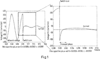
- Fig. 1 illustrates, that a high inrush current occurs during the first milliseconds due to the sudden charge of capacitors located in a LED driver (AC/DC converter), when switching on a LED lamp.
- Typical inrush peak currents are ranging about 10 times higher than then rated current.
- Fig. 2 shows an illustration of the principle of the invention with the Newton's cradle "game"
- the kinetic energy of the left ball can be fully transmitted to the right one during a collision, while leaving the middle and left ball nonmoving.
- the dashed lines show the moving balls. First the left ball moves and impacts in the direction of the arrow on the middle ball, then the right ball moves in the direction of the arrow and the left and middle ball remain motionless. The momentum of the left ball is transmitted or transferred to the right ball.
- Fig. 3 shows an apparatus 1 to switch a light emitting diode (LED) or another load, comprising a mechanical switch 2, which comprises a moving electrode 3, wherein the moving electrode 3 is a contact, which electrically gets in connection with a further contact or electrode 4 to enable a current flow while a closing phase of the mechanical switch 2.
- a mechanical switch 2 which comprises a moving electrode 3, wherein the moving electrode 3 is a contact, which electrically gets in connection with a further contact or electrode 4 to enable a current flow while a closing phase of the mechanical switch 2.
- the apparatus 1 further comprises a body 5, which absorbs or dissipates the kinetic energy and/ or the momentum, which is exerted from the moving electrode 3 on the further contact or electrode 4.
- the principle is as follows: First the moving electrode 3 moves and impacts in the direction of the arrow on the further electrode 4, then the body 5, in this case a ball, moves in the direction of the arrow and the moving electrode 3 and the further electrode 4 remain motionless and are electrically connected. The momentum of the moving electrode 3 is transmitted to the right ball.
- the dashed lines show the moving parts.
- the further contact or electrode 4 is fixed and the body 5 is arranged at least partially behind the further contact or electrode 4 on a side, which is averted to that side of the further contact or electrode 4 where the moving electrode 3 impacts on the further contact or electrode 4.
- the body 5 is a movable body.
- the body 5 is separated from the moving electrode 3 and the further electrode 4.
- the body 5 is made of a polymer.
- the body 5 hangs on a wire and can swing out like a pendulum in the direction of the arrow.
- the ball may also be a polymeric part and connected or hung up in another manner, as described later.
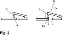
- Fig. 4 schematically shows on the left side an illustration of a standard rocker light switch, and on the right side a further apparatus 1a, comprising a modified light switch case, that shows a third additional contact.
- the movable body 5a is also a contact or an electrode, through which current can flow.
- This body 5a is also movable in the direction of the arrow as shown on the right side of Fig. 4 , when the mechanical switch 2a is closed.
- Fig. 5 schematically shows a modified standard rocker light switch, having a base 6, that comprises a third additional body 5b, which is formed into the polymer of the case 7.
- the third additional body 5b lies just below the bottom electrode 4 of the mechanical switch 2b.
- Fig. 5 insofar shows a further apparatus 1b, wherein the body 5b is a part of a case 7 of the mechanical switch 2b.
- the third body 5b is not completely made of a polymer it can have the function of a third electrode or contact additionally to its dissipating function.
- Fig. 5 it is shown to use the polymer case 7, that is part of a traditional switch, and to transform the polymer part behind the normally fixed electrode 4.
- the polymer part has an appropriate mass and shape in order to move and to take the momentum and kinetic energy of the collisions, while leaving the two metallic electrodes 3, 4 without motion.
- the polymer parts behind fixed contacts namely parts of a switch case 7, advantageously are used and reshaped in order to play the role of a third body 5b, i.e. transforming the already existing physical switch geometry rather than adding a new part.
- a third body 5b is such that the kinetic energy is efficiently dissipated into a moving arm 8 holding the third body 5b. Like this, the new part is not coming back and retransferring its velocity to the two electrodes 3, 4, like it would be for example in a Newton's cradle game.
- the apparatuses 1, 1a, 1b shown here may also be encapsulated as a whole or in part in a case 7.
Landscapes
- Push-Button Switches (AREA)
Abstract
Description
- The invention is related to an apparatus to switch a light emitting diode (LED) or another load, comprising a mechanical switch, which comprises a moving electrode, wherein the moving electrode is a contact, which electrically gets in connection with a further contact or electrode to enable a current flow while a closing phase.
- Nowadays LED lamps are replacing the traditional light bulbs for the sake of their more efficient conversion of electricity into light. This change is even enforced by regulation in most of the countries worldwide.
- However, when switching on a LED lamp, a high inrush current occurs during the first milliseconds due to the sudden charge of capacitors located in the LED driver (AC/DC converter), as illustrated in
Fig. 1 . Typical inrush peak currents are ranging about 10 times higher than then rated current. - One of the issues of mechanical switches is that there is a certain bouncing of the moving electrode during the closing phase. The kinetic energy of the moving electrode can not be dissipated efficiently, which generates a bouncing.
- The main problem occurs, when mechanical switches are used to switch on LEDs, for instance. Since the bounces occur while the current flows, then an arc forms between the two contacts. Due to the very high inrush current that can be reached in switching on LEDs, this can lead to an accelerating contact ageing, or even to a welding of the two contacts.
- The object of the invention therefore is to prevent bounces of electrodes, especially to prevent bounces of a moving electrode of a mechanical switch.
- The object of the invention is achieved by means of the features of
claim 1. - According to this claim the apparatus comprises a body which absorbs or dissipates the kinetic energy and/ or the momentum which is exerted from the moving electrode on the further contact or electrode.
- According to the invention it has been found that the reason for the bounces especially in light switches is due to a collision between two bodies, i.e. the two electrodes when they close. Physically, two bodies entering into an elastic collision are unable to collide without a bounce. The reason is due to the fact that the momentum and energy equations cannot be fulfilled. In order to have two bodies colliding without bouncing, the collision must be either very inelastic, i.e. energy absorbed by the system, or there must be a third body involved in the collision. In the latter case, the equations of momentum and energy can be fulfilled.
- Advantageously the further contact or electrode is fixed and the body is arranged at least partially behind the further contact or electrode on a side which is averted to that side of the further contact or electrode where the moving electrode impacts on the further contact or electrode. Through this a momentum or pulse can be directed and transmitted or transferred to the body. Through this it is possible to add a third body behind a fixed electrode, so that it takes the kinetic energy and dissipates it, so that it prevents the electrodes from bouncing.
- Further advantageously the body is a movable body. A movable body can move in such a way that the two contacts or electrodes remain on their place without bouncing when the mechanical switch is closed and the contacts are electrically connected.
- Advantageously the body is separated from the moving electrode and the further electrode. Through this the body can move independently from the electrically connected electrodes. The body can be lead in a rail or can hang on a wire to be movable in a defined manner.
- Further advantageously the body is also a contact or an electrode, through which current can flow. Through this current can be lead into a combined element having a bigger cross section through which current can flow.
- Further advantageously the body is part of a contact or an electrode. Through this an electrode can be integrated into the body.
- Advantageously the body is made of a polymer or comprises a polymer. A polymer is insulating and has a low density. Polymers are used to create cases or housings of standard mechanical switches.
- Further advantageously the body is a part of a case of the mechanical switch. Alternatively the case itself is the body. Through this, it is possible to use the polymer case that is part of a traditional switch. It is possible to transform a polymer part behind the normally fixed electrode, so that it has an appropriate mass and shape in order to move and to take the momentum and/ or kinetic energy of the collisions, while leaving two metallic electrodes without motion.
- The polymer parts behind fixed contacts, which are parts of the switch case, advantageously are used and reshaped in order to play the role of a third body, i.e. transforming the already existing physical switch geometry rather than adding a new part.
- The geometry of a third body advantageously is such that the kinetic energy is efficiently dissipated into a moving arm holding the third body. Like this, the new part is not coming back and retransferring its velocity to the two electrodes, like it would be for example in a Newton's cradle game.
- The field of the invention relates to mechanical switches, in particular to mechanical switches at low voltages, namely smaller than 1 kV, such as rocker light switches. The invention relates to applications of light switches with LED lamps, or any other type of loads with high inrush currents occurring during the making of the current.
- By a method an apparatus described above is used to avoid any bouncing and/ or arcs in the mechanical switch.
- In the drawings:
- Fig. 1
- shows an inrush current which occurs when the switch closes with a LED load, it is shown that a fast transient phase occurs, which is smaller than 2ms, with a peak inrush current reaching up to about ten times the rated current,
- Fig. 2
- shows an illustration of the principle of the invention with the Newton's cradle "game", the kinetic energy of the left ball can be fully transmitted to the right one during a collision, while leaving the middle and left ball non-moving,
- Fig. 3
- shows an illustration of the principle of the object of this invention disclosure, a third ball, in this case a moving polymer, is placed behind the two contacts to take the momentum and kinetic energy of the collision of the two contacts or electrodes, which should leave the two electrodes motion-less,
- Fig. 4
- shows on the left side an illustration of a standard rocker light switch and on the right side a modified light switch case, that shows a third additional contact, and
- Fig. 5
- schematically shows the case of a mechanical switch, which shows the body as a part of the case.
-
Fig. 1 illustrates, that a high inrush current occurs during the first milliseconds due to the sudden charge of capacitors located in a LED driver (AC/DC converter), when switching on a LED lamp. Typical inrush peak currents are ranging about 10 times higher than then rated current. -
Fig. 2 shows an illustration of the principle of the invention with the Newton's cradle "game", the kinetic energy of the left ball can be fully transmitted to the right one during a collision, while leaving the middle and left ball nonmoving. The dashed lines show the moving balls. First the left ball moves and impacts in the direction of the arrow on the middle ball, then the right ball moves in the direction of the arrow and the left and middle ball remain motionless. The momentum of the left ball is transmitted or transferred to the right ball. -
Fig. 3 shows anapparatus 1 to switch a light emitting diode (LED) or another load, comprising amechanical switch 2, which comprises a movingelectrode 3, wherein the movingelectrode 3 is a contact, which electrically gets in connection with a further contact orelectrode 4 to enable a current flow while a closing phase of themechanical switch 2. - The
apparatus 1 further comprises abody 5, which absorbs or dissipates the kinetic energy and/ or the momentum, which is exerted from the movingelectrode 3 on the further contact orelectrode 4. - The principle is as follows:
First the movingelectrode 3 moves and impacts in the direction of the arrow on thefurther electrode 4, then thebody 5, in this case a ball, moves in the direction of the arrow and the movingelectrode 3 and thefurther electrode 4 remain motionless and are electrically connected. The momentum of the movingelectrode 3 is transmitted to the right ball. The dashed lines show the moving parts. - The further contact or
electrode 4 is fixed and thebody 5 is arranged at least partially behind the further contact orelectrode 4 on a side, which is averted to that side of the further contact orelectrode 4 where the movingelectrode 3 impacts on the further contact orelectrode 4. - The
body 5 is a movable body. Thebody 5 is separated from the movingelectrode 3 and thefurther electrode 4. Thebody 5 is made of a polymer. Thebody 5 hangs on a wire and can swing out like a pendulum in the direction of the arrow. The ball may also be a polymeric part and connected or hung up in another manner, as described later. -
Fig. 4 schematically shows on the left side an illustration of a standard rocker light switch, and on the right side afurther apparatus 1a, comprising a modified light switch case, that shows a third additional contact. - On the right side of
Fig. 4 , it is schematically shown, that themovable body 5a is also a contact or an electrode, through which current can flow. Thisbody 5a is also movable in the direction of the arrow as shown on the right side ofFig. 4 , when themechanical switch 2a is closed. -
Fig. 5 schematically shows a modified standard rocker light switch, having abase 6, that comprises a thirdadditional body 5b, which is formed into the polymer of thecase 7. The thirdadditional body 5b lies just below thebottom electrode 4 of themechanical switch 2b.Fig. 5 insofar shows afurther apparatus 1b, wherein thebody 5b is a part of acase 7 of themechanical switch 2b. - If the
third body 5b is not completely made of a polymer it can have the function of a third electrode or contact additionally to its dissipating function. - In
Fig. 5 it is shown to use thepolymer case 7, that is part of a traditional switch, and to transform the polymer part behind the normally fixedelectrode 4. The polymer part has an appropriate mass and shape in order to move and to take the momentum and kinetic energy of the collisions, while leaving the twometallic electrodes - The polymer parts behind fixed contacts, namely parts of a
switch case 7, advantageously are used and reshaped in order to play the role of athird body 5b, i.e. transforming the already existing physical switch geometry rather than adding a new part. - The geometry of a
third body 5b is such that the kinetic energy is efficiently dissipated into a movingarm 8 holding thethird body 5b. Like this, the new part is not coming back and retransferring its velocity to the twoelectrodes - The
apparatuses case 7.Reference numbers 1, 1a, 1b Apparatus 2, 2a, 2b Mechanical switch 3 Moving electrode 4 Further electrode 5, 5a, 5b Body 6 Base of 7 7 Case 8 Holding arm of 5b
Claims (9)
- Apparatus (1, 1a, 1b) to switch a light emitting diode (LED) or another load, comprising a mechanical switch (2, 2a, 2b), which comprises a moving electrode (3), wherein the moving electrode (3) is a contact, which electrically gets in connection with a further contact or electrode (4) to enable a current flow while a closing phase,
characterized in that the apparatus (1, 1a, 1b) comprises a body (5, 5a, 5b) which absorbs or dissipates the kinetic energy and/ or the momentum which is exerted from the moving electrode (3) on the further contact or electrode (4). - Apparatus according to claim 1, characterized in that the further contact or electrode (4) is fixed and the body (5, 5a, 5b) is arranged at least partially behind the further contact or electrode (4) on a side which is averted to that side of the further contact or electrode (4), where the moving electrode (3) impacts on the further contact or electrode (4).
- Apparatus according to claim 1 or 2, characterized in that the body (5, 5a, 5b) is a movable body.
- Apparatus according to one of the preceding claims, characterized in that the body (5, 5a, 5b) is separated from the moving electrode (3) and the further electrode (4).
- Apparatus according to one of the preceding claims, characterized in that the body (5a, 5b) is also a contact or an electrode, through which current can flow.
- Apparatus according to one of the claims 1 to 4, characterized in that the body (5b) is a part of a contact or an electrode (4).
- Apparatus according to one of the preceding claims, characterized in that the body (5, 5a, 5b) is made of a polymer or comprises a polymer.
- Apparatus according to one of the preceding claims, characterized in that the body (5b) is a part of a case (7) of the mechanical switch (2b) or that the case (7) itself is the body.
- Method of use of an apparatus (1, 1a, 1b) according to one of the preceding claims to avoid any bouncing or arcs in the mechanical switch (2, 2a, 2b).
Priority Applications (1)
| Application Number | Priority Date | Filing Date | Title |
|---|---|---|---|
| EP18182430.1A EP3594978B1 (en) | 2018-07-09 | 2018-07-09 | Apparatus to switch a led |
Applications Claiming Priority (1)
| Application Number | Priority Date | Filing Date | Title |
|---|---|---|---|
| EP18182430.1A EP3594978B1 (en) | 2018-07-09 | 2018-07-09 | Apparatus to switch a led |
Publications (2)
| Publication Number | Publication Date |
|---|---|
| EP3594978A1 true EP3594978A1 (en) | 2020-01-15 |
| EP3594978B1 EP3594978B1 (en) | 2022-05-11 |
Family
ID=62904345
Family Applications (1)
| Application Number | Title | Priority Date | Filing Date |
|---|---|---|---|
| EP18182430.1A Active EP3594978B1 (en) | 2018-07-09 | 2018-07-09 | Apparatus to switch a led |
Country Status (1)
| Country | Link |
|---|---|
| EP (1) | EP3594978B1 (en) |
Citations (3)
| Publication number | Priority date | Publication date | Assignee | Title |
|---|---|---|---|---|
| GB629300A (en) * | 1945-12-08 | 1949-09-16 | Frederick Leonard Cook | Improvements in electrical snap acting switches |
| US2743330A (en) * | 1954-04-12 | 1956-04-24 | Ludwig Louis | Silent switch structure |
| EP0560696A1 (en) * | 1992-03-13 | 1993-09-15 | Schneider Electric Sa | Contact for moulded case circuit breaker |
-
2018
- 2018-07-09 EP EP18182430.1A patent/EP3594978B1/en active Active
Patent Citations (3)
| Publication number | Priority date | Publication date | Assignee | Title |
|---|---|---|---|---|
| GB629300A (en) * | 1945-12-08 | 1949-09-16 | Frederick Leonard Cook | Improvements in electrical snap acting switches |
| US2743330A (en) * | 1954-04-12 | 1956-04-24 | Ludwig Louis | Silent switch structure |
| EP0560696A1 (en) * | 1992-03-13 | 1993-09-15 | Schneider Electric Sa | Contact for moulded case circuit breaker |
Also Published As
| Publication number | Publication date |
|---|---|
| EP3594978B1 (en) | 2022-05-11 |
Similar Documents
| Publication | Publication Date | Title |
|---|---|---|
| US7342754B2 (en) | Bypass circuit to prevent arcing in a switching device | |
| US8110769B2 (en) | Vacuum circuit breaker | |
| JP6487573B2 (en) | Contactor assembly | |
| ES2440615T3 (en) | Electromagnetic switching device | |
| CN102184795A (en) | Fast vacuum circuit breaker used for protecting high-power power electronic converter | |
| US10727008B2 (en) | Contact device for an electrical switch, and electrical switch | |
| CN101925972A (en) | Pyrotechnic short-circuit device | |
| CN101728101A (en) | Micro switch | |
| US20220344115A1 (en) | Vacuum circuit interrupter with dual plate actuation | |
| CN101128896B (en) | Contact system for an electrical switching device | |
| EP3594978B1 (en) | Apparatus to switch a led | |
| CN104124110B (en) | A kind of asymmetric repulsive force mechanism | |
| US11043343B2 (en) | Assembly and method for damping contact bounce in high-voltage circuit breakers | |
| EP3594977B1 (en) | Apparatus to switch a led | |
| US20180204698A1 (en) | Magnet armature, contactor having a magnetic armature, and method for switching a contactor | |
| US12033813B2 (en) | Vacuum switching device for medium- and high-voltage applications | |
| EP3662495A1 (en) | An armature for electromagnetic actuator, an electromagnetic actuator, a switch device and a method for manufacturing an armature | |
| RU162074U1 (en) | ELECTROMAGNETIC HIGH VOLTAGE CONTACTOR | |
| EP4348690B1 (en) | Switching device and method for operating a switching device | |
| CN204011313U (en) | A kind of asymmetric repulsive force mechanism | |
| JP2012221557A (en) | Puffer type gas circuit breaker with input resistance contact | |
| CN106537539A (en) | Multipolar power contactor | |
| EP3913647B1 (en) | A switch system | |
| JP2001057142A (en) | Fast switching mechanical switching contacts | |
| CN120089553B (en) | An operating mechanism for an ultra-high voltage circuit breaker |
Legal Events
| Date | Code | Title | Description |
|---|---|---|---|
| PUAI | Public reference made under article 153(3) epc to a published international application that has entered the european phase |
Free format text: ORIGINAL CODE: 0009012 |
|
| STAA | Information on the status of an ep patent application or granted ep patent |
Free format text: STATUS: THE APPLICATION HAS BEEN PUBLISHED |
|
| AK | Designated contracting states |
Kind code of ref document: A1 Designated state(s): AL AT BE BG CH CY CZ DE DK EE ES FI FR GB GR HR HU IE IS IT LI LT LU LV MC MK MT NL NO PL PT RO RS SE SI SK SM TR |
|
| AX | Request for extension of the european patent |
Extension state: BA ME |
|
| STAA | Information on the status of an ep patent application or granted ep patent |
Free format text: STATUS: REQUEST FOR EXAMINATION WAS MADE |
|
| 17P | Request for examination filed |
Effective date: 20200608 |
|
| RBV | Designated contracting states (corrected) |
Designated state(s): AL AT BE BG CH CY CZ DE DK EE ES FI FR GB GR HR HU IE IS IT LI LT LU LV MC MK MT NL NO PL PT RO RS SE SI SK SM TR |
|
| GRAP | Despatch of communication of intention to grant a patent |
Free format text: ORIGINAL CODE: EPIDOSNIGR1 |
|
| STAA | Information on the status of an ep patent application or granted ep patent |
Free format text: STATUS: GRANT OF PATENT IS INTENDED |
|
| INTG | Intention to grant announced |
Effective date: 20211217 |
|
| RAP3 | Party data changed (applicant data changed or rights of an application transferred) |
Owner name: ABB SCHWEIZ AG |
|
| GRAS | Grant fee paid |
Free format text: ORIGINAL CODE: EPIDOSNIGR3 |
|
| GRAA | (expected) grant |
Free format text: ORIGINAL CODE: 0009210 |
|
| STAA | Information on the status of an ep patent application or granted ep patent |
Free format text: STATUS: THE PATENT HAS BEEN GRANTED |
|
| AK | Designated contracting states |
Kind code of ref document: B1 Designated state(s): AL AT BE BG CH CY CZ DE DK EE ES FI FR GB GR HR HU IE IS IT LI LT LU LV MC MK MT NL NO PL PT RO RS SE SI SK SM TR |
|
| REG | Reference to a national code |
Ref country code: GB Ref legal event code: FG4D |
|
| REG | Reference to a national code |
Ref country code: CH Ref legal event code: EP |
|
| REG | Reference to a national code |
Ref country code: AT Ref legal event code: REF Ref document number: 1492164 Country of ref document: AT Kind code of ref document: T Effective date: 20220515 |
|
| REG | Reference to a national code |
Ref country code: DE Ref legal event code: R096 Ref document number: 602018035290 Country of ref document: DE |
|
| REG | Reference to a national code |
Ref country code: IE Ref legal event code: FG4D |
|
| REG | Reference to a national code |
Ref country code: LT Ref legal event code: MG9D |
|
| REG | Reference to a national code |
Ref country code: NL Ref legal event code: MP Effective date: 20220511 |
|
| REG | Reference to a national code |
Ref country code: AT Ref legal event code: MK05 Ref document number: 1492164 Country of ref document: AT Kind code of ref document: T Effective date: 20220511 |
|
| PG25 | Lapsed in a contracting state [announced via postgrant information from national office to epo] |
Ref country code: SE Free format text: LAPSE BECAUSE OF FAILURE TO SUBMIT A TRANSLATION OF THE DESCRIPTION OR TO PAY THE FEE WITHIN THE PRESCRIBED TIME-LIMIT Effective date: 20220511 Ref country code: PT Free format text: LAPSE BECAUSE OF FAILURE TO SUBMIT A TRANSLATION OF THE DESCRIPTION OR TO PAY THE FEE WITHIN THE PRESCRIBED TIME-LIMIT Effective date: 20220912 Ref country code: NO Free format text: LAPSE BECAUSE OF FAILURE TO SUBMIT A TRANSLATION OF THE DESCRIPTION OR TO PAY THE FEE WITHIN THE PRESCRIBED TIME-LIMIT Effective date: 20220811 Ref country code: NL Free format text: LAPSE BECAUSE OF FAILURE TO SUBMIT A TRANSLATION OF THE DESCRIPTION OR TO PAY THE FEE WITHIN THE PRESCRIBED TIME-LIMIT Effective date: 20220511 Ref country code: LT Free format text: LAPSE BECAUSE OF FAILURE TO SUBMIT A TRANSLATION OF THE DESCRIPTION OR TO PAY THE FEE WITHIN THE PRESCRIBED TIME-LIMIT Effective date: 20220511 Ref country code: HR Free format text: LAPSE BECAUSE OF FAILURE TO SUBMIT A TRANSLATION OF THE DESCRIPTION OR TO PAY THE FEE WITHIN THE PRESCRIBED TIME-LIMIT Effective date: 20220511 Ref country code: GR Free format text: LAPSE BECAUSE OF FAILURE TO SUBMIT A TRANSLATION OF THE DESCRIPTION OR TO PAY THE FEE WITHIN THE PRESCRIBED TIME-LIMIT Effective date: 20220812 Ref country code: FI Free format text: LAPSE BECAUSE OF FAILURE TO SUBMIT A TRANSLATION OF THE DESCRIPTION OR TO PAY THE FEE WITHIN THE PRESCRIBED TIME-LIMIT Effective date: 20220511 Ref country code: ES Free format text: LAPSE BECAUSE OF FAILURE TO SUBMIT A TRANSLATION OF THE DESCRIPTION OR TO PAY THE FEE WITHIN THE PRESCRIBED TIME-LIMIT Effective date: 20220511 Ref country code: BG Free format text: LAPSE BECAUSE OF FAILURE TO SUBMIT A TRANSLATION OF THE DESCRIPTION OR TO PAY THE FEE WITHIN THE PRESCRIBED TIME-LIMIT Effective date: 20220811 Ref country code: AT Free format text: LAPSE BECAUSE OF FAILURE TO SUBMIT A TRANSLATION OF THE DESCRIPTION OR TO PAY THE FEE WITHIN THE PRESCRIBED TIME-LIMIT Effective date: 20220511 |
|
| PG25 | Lapsed in a contracting state [announced via postgrant information from national office to epo] |
Ref country code: RS Free format text: LAPSE BECAUSE OF FAILURE TO SUBMIT A TRANSLATION OF THE DESCRIPTION OR TO PAY THE FEE WITHIN THE PRESCRIBED TIME-LIMIT Effective date: 20220511 Ref country code: PL Free format text: LAPSE BECAUSE OF FAILURE TO SUBMIT A TRANSLATION OF THE DESCRIPTION OR TO PAY THE FEE WITHIN THE PRESCRIBED TIME-LIMIT Effective date: 20220511 Ref country code: LV Free format text: LAPSE BECAUSE OF FAILURE TO SUBMIT A TRANSLATION OF THE DESCRIPTION OR TO PAY THE FEE WITHIN THE PRESCRIBED TIME-LIMIT Effective date: 20220511 Ref country code: IS Free format text: LAPSE BECAUSE OF FAILURE TO SUBMIT A TRANSLATION OF THE DESCRIPTION OR TO PAY THE FEE WITHIN THE PRESCRIBED TIME-LIMIT Effective date: 20220911 |
|
| PG25 | Lapsed in a contracting state [announced via postgrant information from national office to epo] |
Ref country code: SM Free format text: LAPSE BECAUSE OF FAILURE TO SUBMIT A TRANSLATION OF THE DESCRIPTION OR TO PAY THE FEE WITHIN THE PRESCRIBED TIME-LIMIT Effective date: 20220511 Ref country code: SK Free format text: LAPSE BECAUSE OF FAILURE TO SUBMIT A TRANSLATION OF THE DESCRIPTION OR TO PAY THE FEE WITHIN THE PRESCRIBED TIME-LIMIT Effective date: 20220511 Ref country code: RO Free format text: LAPSE BECAUSE OF FAILURE TO SUBMIT A TRANSLATION OF THE DESCRIPTION OR TO PAY THE FEE WITHIN THE PRESCRIBED TIME-LIMIT Effective date: 20220511 Ref country code: EE Free format text: LAPSE BECAUSE OF FAILURE TO SUBMIT A TRANSLATION OF THE DESCRIPTION OR TO PAY THE FEE WITHIN THE PRESCRIBED TIME-LIMIT Effective date: 20220511 Ref country code: DK Free format text: LAPSE BECAUSE OF FAILURE TO SUBMIT A TRANSLATION OF THE DESCRIPTION OR TO PAY THE FEE WITHIN THE PRESCRIBED TIME-LIMIT Effective date: 20220511 Ref country code: CZ Free format text: LAPSE BECAUSE OF FAILURE TO SUBMIT A TRANSLATION OF THE DESCRIPTION OR TO PAY THE FEE WITHIN THE PRESCRIBED TIME-LIMIT Effective date: 20220511 |
|
| REG | Reference to a national code |
Ref country code: DE Ref legal event code: R097 Ref document number: 602018035290 Country of ref document: DE |
|
| PG25 | Lapsed in a contracting state [announced via postgrant information from national office to epo] |
Ref country code: MC Free format text: LAPSE BECAUSE OF FAILURE TO SUBMIT A TRANSLATION OF THE DESCRIPTION OR TO PAY THE FEE WITHIN THE PRESCRIBED TIME-LIMIT Effective date: 20220511 |
|
| REG | Reference to a national code |
Ref country code: CH Ref legal event code: PL |
|
| PLBE | No opposition filed within time limit |
Free format text: ORIGINAL CODE: 0009261 |
|
| STAA | Information on the status of an ep patent application or granted ep patent |
Free format text: STATUS: NO OPPOSITION FILED WITHIN TIME LIMIT |
|
| REG | Reference to a national code |
Ref country code: BE Ref legal event code: MM Effective date: 20220731 |
|
| PG25 | Lapsed in a contracting state [announced via postgrant information from national office to epo] |
Ref country code: AL Free format text: LAPSE BECAUSE OF FAILURE TO SUBMIT A TRANSLATION OF THE DESCRIPTION OR TO PAY THE FEE WITHIN THE PRESCRIBED TIME-LIMIT Effective date: 20220511 |
|
| 26N | No opposition filed |
Effective date: 20230214 |
|
| GBPC | Gb: european patent ceased through non-payment of renewal fee |
Effective date: 20220811 |
|
| PG25 | Lapsed in a contracting state [announced via postgrant information from national office to epo] |
Ref country code: LU Free format text: LAPSE BECAUSE OF NON-PAYMENT OF DUE FEES Effective date: 20220709 Ref country code: LI Free format text: LAPSE BECAUSE OF NON-PAYMENT OF DUE FEES Effective date: 20220731 Ref country code: FR Free format text: LAPSE BECAUSE OF NON-PAYMENT OF DUE FEES Effective date: 20220711 Ref country code: CH Free format text: LAPSE BECAUSE OF NON-PAYMENT OF DUE FEES Effective date: 20220731 |
|
| PG25 | Lapsed in a contracting state [announced via postgrant information from national office to epo] |
Ref country code: SI Free format text: LAPSE BECAUSE OF FAILURE TO SUBMIT A TRANSLATION OF THE DESCRIPTION OR TO PAY THE FEE WITHIN THE PRESCRIBED TIME-LIMIT Effective date: 20220511 Ref country code: BE Free format text: LAPSE BECAUSE OF NON-PAYMENT OF DUE FEES Effective date: 20220731 |
|
| PG25 | Lapsed in a contracting state [announced via postgrant information from national office to epo] |
Ref country code: IE Free format text: LAPSE BECAUSE OF NON-PAYMENT OF DUE FEES Effective date: 20220709 |
|
| PG25 | Lapsed in a contracting state [announced via postgrant information from national office to epo] |
Ref country code: GB Free format text: LAPSE BECAUSE OF NON-PAYMENT OF DUE FEES Effective date: 20220811 |
|
| PG25 | Lapsed in a contracting state [announced via postgrant information from national office to epo] |
Ref country code: IT Free format text: LAPSE BECAUSE OF FAILURE TO SUBMIT A TRANSLATION OF THE DESCRIPTION OR TO PAY THE FEE WITHIN THE PRESCRIBED TIME-LIMIT Effective date: 20220511 |
|
| PG25 | Lapsed in a contracting state [announced via postgrant information from national office to epo] |
Ref country code: HU Free format text: LAPSE BECAUSE OF FAILURE TO SUBMIT A TRANSLATION OF THE DESCRIPTION OR TO PAY THE FEE WITHIN THE PRESCRIBED TIME-LIMIT; INVALID AB INITIO Effective date: 20180709 |
|
| PG25 | Lapsed in a contracting state [announced via postgrant information from national office to epo] |
Ref country code: MK Free format text: LAPSE BECAUSE OF FAILURE TO SUBMIT A TRANSLATION OF THE DESCRIPTION OR TO PAY THE FEE WITHIN THE PRESCRIBED TIME-LIMIT Effective date: 20220511 Ref country code: CY Free format text: LAPSE BECAUSE OF FAILURE TO SUBMIT A TRANSLATION OF THE DESCRIPTION OR TO PAY THE FEE WITHIN THE PRESCRIBED TIME-LIMIT Effective date: 20220511 |
|
| PG25 | Lapsed in a contracting state [announced via postgrant information from national office to epo] |
Ref country code: MT Free format text: LAPSE BECAUSE OF FAILURE TO SUBMIT A TRANSLATION OF THE DESCRIPTION OR TO PAY THE FEE WITHIN THE PRESCRIBED TIME-LIMIT Effective date: 20220511 |
|
| PG25 | Lapsed in a contracting state [announced via postgrant information from national office to epo] |
Ref country code: BG Free format text: LAPSE BECAUSE OF FAILURE TO SUBMIT A TRANSLATION OF THE DESCRIPTION OR TO PAY THE FEE WITHIN THE PRESCRIBED TIME-LIMIT Effective date: 20220511 |
|
| PG25 | Lapsed in a contracting state [announced via postgrant information from national office to epo] |
Ref country code: BG Free format text: LAPSE BECAUSE OF FAILURE TO SUBMIT A TRANSLATION OF THE DESCRIPTION OR TO PAY THE FEE WITHIN THE PRESCRIBED TIME-LIMIT Effective date: 20220511 |
|
| REG | Reference to a national code |
Ref country code: DE Ref legal event code: R082 Ref document number: 602018035290 Country of ref document: DE Representative=s name: ZIMMERMANN & PARTNER PATENTANWAELTE MBB, DE |
|
| PGFP | Annual fee paid to national office [announced via postgrant information from national office to epo] |
Ref country code: DE Payment date: 20250722 Year of fee payment: 8 |
|
| PG25 | Lapsed in a contracting state [announced via postgrant information from national office to epo] |
Ref country code: TR Free format text: LAPSE BECAUSE OF FAILURE TO SUBMIT A TRANSLATION OF THE DESCRIPTION OR TO PAY THE FEE WITHIN THE PRESCRIBED TIME-LIMIT Effective date: 20220511 |