EP3594906B1 - Verfahren und vorrichtung zur bereitstellung einer erweiterten realität und computerprogramm - Google Patents
Verfahren und vorrichtung zur bereitstellung einer erweiterten realität und computerprogramm Download PDFInfo
- Publication number
- EP3594906B1 EP3594906B1 EP17899941.3A EP17899941A EP3594906B1 EP 3594906 B1 EP3594906 B1 EP 3594906B1 EP 17899941 A EP17899941 A EP 17899941A EP 3594906 B1 EP3594906 B1 EP 3594906B1
- Authority
- EP
- European Patent Office
- Prior art keywords
- plane
- information
- augmented reality
- terminal
- sensor
- Prior art date
- Legal status (The legal status is an assumption and is not a legal conclusion. Google has not performed a legal analysis and makes no representation as to the accuracy of the status listed.)
- Active
Links
- 230000003190 augmentative effect Effects 0.000 title claims description 109
- 238000000034 method Methods 0.000 title claims description 32
- 238000004590 computer program Methods 0.000 title claims description 17
- 239000013598 vector Substances 0.000 claims description 67
- 238000009877 rendering Methods 0.000 claims description 15
- 230000001133 acceleration Effects 0.000 claims description 9
- 238000010586 diagram Methods 0.000 description 10
- 230000005484 gravity Effects 0.000 description 8
- 238000012545 processing Methods 0.000 description 5
- 239000003086 colorant Substances 0.000 description 4
- 230000006870 function Effects 0.000 description 4
- 230000000694 effects Effects 0.000 description 3
- 238000005259 measurement Methods 0.000 description 3
- 238000004364 calculation method Methods 0.000 description 2
- XLYOFNOQVPJJNP-UHFFFAOYSA-N water Substances O XLYOFNOQVPJJNP-UHFFFAOYSA-N 0.000 description 2
- PEDCQBHIVMGVHV-UHFFFAOYSA-N Glycerine Chemical compound OCC(O)CO PEDCQBHIVMGVHV-UHFFFAOYSA-N 0.000 description 1
- 238000013459 approach Methods 0.000 description 1
- 238000004891 communication Methods 0.000 description 1
- 230000001419 dependent effect Effects 0.000 description 1
- 230000005358 geomagnetic field Effects 0.000 description 1
- 238000004519 manufacturing process Methods 0.000 description 1
- 238000011017 operating method Methods 0.000 description 1
- 230000003287 optical effect Effects 0.000 description 1
- 238000004088 simulation Methods 0.000 description 1
- 230000003068 static effect Effects 0.000 description 1
Images


Classifications
-
- G—PHYSICS
- G06—COMPUTING; CALCULATING OR COUNTING
- G06T—IMAGE DATA PROCESSING OR GENERATION, IN GENERAL
- G06T19/00—Manipulating 3D models or images for computer graphics
- G06T19/006—Mixed reality
-
- G—PHYSICS
- G01—MEASURING; TESTING
- G01S—RADIO DIRECTION-FINDING; RADIO NAVIGATION; DETERMINING DISTANCE OR VELOCITY BY USE OF RADIO WAVES; LOCATING OR PRESENCE-DETECTING BY USE OF THE REFLECTION OR RERADIATION OF RADIO WAVES; ANALOGOUS ARRANGEMENTS USING OTHER WAVES
- G01S17/00—Systems using the reflection or reradiation of electromagnetic waves other than radio waves, e.g. lidar systems
- G01S17/02—Systems using the reflection of electromagnetic waves other than radio waves
- G01S17/06—Systems determining position data of a target
- G01S17/42—Simultaneous measurement of distance and other co-ordinates
-
- G—PHYSICS
- G01—MEASURING; TESTING
- G01B—MEASURING LENGTH, THICKNESS OR SIMILAR LINEAR DIMENSIONS; MEASURING ANGLES; MEASURING AREAS; MEASURING IRREGULARITIES OF SURFACES OR CONTOURS
- G01B11/00—Measuring arrangements characterised by the use of optical techniques
- G01B11/02—Measuring arrangements characterised by the use of optical techniques for measuring length, width or thickness
-
- G—PHYSICS
- G01—MEASURING; TESTING
- G01P—MEASURING LINEAR OR ANGULAR SPEED, ACCELERATION, DECELERATION, OR SHOCK; INDICATING PRESENCE, ABSENCE, OR DIRECTION, OF MOVEMENT
- G01P13/00—Indicating or recording presence, absence, or direction, of movement
- G01P13/02—Indicating direction only, e.g. by weather vane
-
- G—PHYSICS
- G01—MEASURING; TESTING
- G01P—MEASURING LINEAR OR ANGULAR SPEED, ACCELERATION, DECELERATION, OR SHOCK; INDICATING PRESENCE, ABSENCE, OR DIRECTION, OF MOVEMENT
- G01P15/00—Measuring acceleration; Measuring deceleration; Measuring shock, i.e. sudden change of acceleration
- G01P15/18—Measuring acceleration; Measuring deceleration; Measuring shock, i.e. sudden change of acceleration in two or more dimensions
-
- G—PHYSICS
- G01—MEASURING; TESTING
- G01S—RADIO DIRECTION-FINDING; RADIO NAVIGATION; DETERMINING DISTANCE OR VELOCITY BY USE OF RADIO WAVES; LOCATING OR PRESENCE-DETECTING BY USE OF THE REFLECTION OR RERADIATION OF RADIO WAVES; ANALOGOUS ARRANGEMENTS USING OTHER WAVES
- G01S17/00—Systems using the reflection or reradiation of electromagnetic waves other than radio waves, e.g. lidar systems
- G01S17/02—Systems using the reflection of electromagnetic waves other than radio waves
- G01S17/06—Systems determining position data of a target
- G01S17/08—Systems determining position data of a target for measuring distance only
-
- G—PHYSICS
- G01—MEASURING; TESTING
- G01S—RADIO DIRECTION-FINDING; RADIO NAVIGATION; DETERMINING DISTANCE OR VELOCITY BY USE OF RADIO WAVES; LOCATING OR PRESENCE-DETECTING BY USE OF THE REFLECTION OR RERADIATION OF RADIO WAVES; ANALOGOUS ARRANGEMENTS USING OTHER WAVES
- G01S17/00—Systems using the reflection or reradiation of electromagnetic waves other than radio waves, e.g. lidar systems
- G01S17/86—Combinations of lidar systems with systems other than lidar, radar or sonar, e.g. with direction finders
-
- G—PHYSICS
- G01—MEASURING; TESTING
- G01S—RADIO DIRECTION-FINDING; RADIO NAVIGATION; DETERMINING DISTANCE OR VELOCITY BY USE OF RADIO WAVES; LOCATING OR PRESENCE-DETECTING BY USE OF THE REFLECTION OR RERADIATION OF RADIO WAVES; ANALOGOUS ARRANGEMENTS USING OTHER WAVES
- G01S7/00—Details of systems according to groups G01S13/00, G01S15/00, G01S17/00
- G01S7/48—Details of systems according to groups G01S13/00, G01S15/00, G01S17/00 of systems according to group G01S17/00
- G01S7/4802—Details of systems according to groups G01S13/00, G01S15/00, G01S17/00 of systems according to group G01S17/00 using analysis of echo signal for target characterisation; Target signature; Target cross-section
-
- G—PHYSICS
- G06—COMPUTING; CALCULATING OR COUNTING
- G06F—ELECTRIC DIGITAL DATA PROCESSING
- G06F3/00—Input arrangements for transferring data to be processed into a form capable of being handled by the computer; Output arrangements for transferring data from processing unit to output unit, e.g. interface arrangements
- G06F3/01—Input arrangements or combined input and output arrangements for interaction between user and computer
- G06F3/011—Arrangements for interaction with the human body, e.g. for user immersion in virtual reality
-
- G—PHYSICS
- G06—COMPUTING; CALCULATING OR COUNTING
- G06F—ELECTRIC DIGITAL DATA PROCESSING
- G06F3/00—Input arrangements for transferring data to be processed into a form capable of being handled by the computer; Output arrangements for transferring data from processing unit to output unit, e.g. interface arrangements
- G06F3/01—Input arrangements or combined input and output arrangements for interaction between user and computer
- G06F3/03—Arrangements for converting the position or the displacement of a member into a coded form
- G06F3/033—Pointing devices displaced or positioned by the user, e.g. mice, trackballs, pens or joysticks; Accessories therefor
- G06F3/0346—Pointing devices displaced or positioned by the user, e.g. mice, trackballs, pens or joysticks; Accessories therefor with detection of the device orientation or free movement in a 3D space, e.g. 3D mice, 6-DOF [six degrees of freedom] pointers using gyroscopes, accelerometers or tilt-sensors
-
- G—PHYSICS
- G06—COMPUTING; CALCULATING OR COUNTING
- G06T—IMAGE DATA PROCESSING OR GENERATION, IN GENERAL
- G06T7/00—Image analysis
- G06T7/30—Determination of transform parameters for the alignment of images, i.e. image registration
-
- G—PHYSICS
- G06—COMPUTING; CALCULATING OR COUNTING
- G06T—IMAGE DATA PROCESSING OR GENERATION, IN GENERAL
- G06T7/00—Image analysis
- G06T7/50—Depth or shape recovery
- G06T7/521—Depth or shape recovery from laser ranging, e.g. using interferometry; from the projection of structured light
-
- G—PHYSICS
- G06—COMPUTING; CALCULATING OR COUNTING
- G06T—IMAGE DATA PROCESSING OR GENERATION, IN GENERAL
- G06T7/00—Image analysis
- G06T7/70—Determining position or orientation of objects or cameras
-
- G—PHYSICS
- G06—COMPUTING; CALCULATING OR COUNTING
- G06T—IMAGE DATA PROCESSING OR GENERATION, IN GENERAL
- G06T7/00—Image analysis
- G06T7/70—Determining position or orientation of objects or cameras
- G06T7/73—Determining position or orientation of objects or cameras using feature-based methods
-
- G—PHYSICS
- G01—MEASURING; TESTING
- G01S—RADIO DIRECTION-FINDING; RADIO NAVIGATION; DETERMINING DISTANCE OR VELOCITY BY USE OF RADIO WAVES; LOCATING OR PRESENCE-DETECTING BY USE OF THE REFLECTION OR RERADIATION OF RADIO WAVES; ANALOGOUS ARRANGEMENTS USING OTHER WAVES
- G01S15/00—Systems using the reflection or reradiation of acoustic waves, e.g. sonar systems
- G01S15/02—Systems using the reflection or reradiation of acoustic waves, e.g. sonar systems using reflection of acoustic waves
- G01S15/06—Systems determining the position data of a target
- G01S15/08—Systems for measuring distance only
-
- G—PHYSICS
- G06—COMPUTING; CALCULATING OR COUNTING
- G06T—IMAGE DATA PROCESSING OR GENERATION, IN GENERAL
- G06T2219/00—Indexing scheme for manipulating 3D models or images for computer graphics
- G06T2219/008—Cut plane or projection plane definition
Definitions
- the determining may include determining an attribute of the plane based on the normal vector and determining the parameter considering the determined attribute.
- the plane information may be direction information of the plane
- the determining may include determining a type of the object based on the attribute and determining a rendering direction of the object based on the direction information of the plane
- the displaying may include two-dimensionally rendering 3-dimensional (3D) information for displaying the object, according to the rendering direction, and two-dimensionally displaying the object.
- the augmented reality providing system provided according to an embodiment of the present disclosure provides augmented reality, in which an object is displayed in real-time while overlapping an image captured by a camera.
- augmented reality in which an object is displayed in real-time while overlapping an image captured by a camera.
- a plane that is actually present around the user terminal 20 is recognized, an attribute of the recognized plane is determined, and a virtual object is displayed in real-time accordingly together with the image captured by the camera.
- the user terminal 20 may be any terminal in which an augmented reality providing program provided according to an embodiment of the present disclosure is installable.
- the user terminal 20 may be a portable terminal.
- the portable terminal is illustrated as a smart phone, but the aspect of the present disclosure is not limited thereto, and as described above, a terminal in which a computer program is installable may be unlimitedly employed.
- the user terminal 20 includes a wearable computer, a head-mounted display (HMD), or the like.
- the user terminal 20 includes a display unit displaying a screen and the camera capturing an image.
- the display unit may include a display panel directly displaying the image, but is not limited thereto, and may be a projecting-type display device.
- the user terminal 20 may further include a distance sensor and a direction sensor.
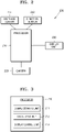
- the server 10 may include a memory, an input/output unit, a program storage unit, a control unit, and the like.
- the augmented reality providing apparatus 200 may be any type of apparatus including a processor processing data.
- the augmented reality providing apparatus 200 may include at least one processor.
- the 'processor' may denote a data processing apparatus embedded in hardware and having a physically structured circuit for performing a function expressed in code or a command in a program.
- Examples of the data processing apparatus embedded in hardware as such may include processing apparatuses, such as a microprocessor, a central processing unit (CPU), a processor core, a multiprocessor, an application-specific integrated circuit (ASIC), and a field programmable gate array (FPGA), but the scope of the present disclosure is not limited thereto.
- the augmented reality providing apparatus 200 may be driven while being included in another hardware apparatus, such as a microprocessor or a general-purpose computer system.
- the augmented reality providing apparatus 200 may be mounted on the user terminal 20 of FIG. 1 .
- the augmented reality providing apparatus 200 may further include a communication unit including hardware and software required to transmit and receive signals to and from another network apparatus (for example, the server 10), via wired or wireless connection.
- a communication unit including hardware and software required to transmit and receive signals to and from another network apparatus (for example, the server 10), via wired or wireless connection.
- the augmented reality providing apparatus 200 recognizes a plane according to a measurement value of a distance sensor 221, determines an attribute of the plane by using a measurement value of a direction sensor 222, and displays a virtual object in real-time accordingly, on a display unit 230, together with an image captured by a camera 223, by using a processor 210.
- the augmented reality providing apparatus 200 includes the processor 210, the distance sensor 221, the direction sensor 222, the camera 223, and the display unit 230.
- the distance sensor 221 obtains distances from the distance sensor 221 to a plurality of points in front.
- the distance sensor 221 further obtains direction information to the plurality of points.
- the distance sensor 221 may obtain the distances to and directions of the plurality of points on the plane, and the processor 210 may obtain plane information including the plurality of points, for example, a plane equation, a plane vector, and the like, as information for defining the plane, by using information measured by the distance sensor 221.
- the direction sensor 222 measures a direction the user terminal 20 faces.
- the direction sensor 222 may be, for example, an acceleration sensor, an angular speed sensor, a geomagnetic field sensor, or a combination thereof.
- the direction sensor 222 may recognize a gravity direction to measure a direction a terminal faces based on the gravity direction.
- the gravity direction is an example of a reference direction, and thus the direction is not limited thereto.
- the camera 223 captures an image.
- the display unit 230 includes a display panel and displays an image according to control of the processor 210.
- FIG. 3 is a block diagram showing a configuration of the processor 210 shown in FIG. 2 .
- the processor 21 includes a signal obtaining unit 211, a calculating unit 212, and a display control unit 213.
- Blocks included in the processor 210 of FIG. 3 may all be realized on one processor and distinguished according to functions, but are not limited thereto, and may be realized on individual processors. Also, the functions of the blocks may be integrally realized through one program code, or may be prepared in individual program codes, and the program codes may interwork such that the processor 210 of FIG. 3 and the augmented reality providing apparatus 200 of FIG. 2 provide augmented reality.
- the calculating unit 212 processes a signal obtained by the signal obtaining unit 211.
- the signal obtaining unit 211 obtains distances to a plurality of points from the distance sensor 221 and the calculating unit 212 obtains plane information of a plane including the plurality of points by using the obtained distances.
- the plane information is direction information of the plane based on a direction where the distance sensor 221 is provided, and may be expressed in a form of a plane equation, a plane vector, or the like.
- the plane information may be obtained from the plurality of points by using a random sample consensus (RANSAC) technique, but an embodiment is not limited thereto.
- RNSAC random sample consensus
- the signal obtaining unit 211 obtains direction information of a terminal measured by the direction sensor 222, and the calculating unit 212 obtains a normal vector of the plane by using the pre-obtained plane information and the direction information of the terminal.
- the calculating unit 212 converts a reference direction of the plane information from a direction of the terminal (or a direction in which the distance sensor 221 provided in the terminal faces) to a reference direction of the direction sensor 222.
- the calculating unit 212 finally obtains direction information of the plane based on the direction of gravity by moving the direction information of the plane obtained based on the direction of the terminal by the direction information (based on the direction of gravity recognized by an acceleration sensor) of the terminal measured by the direction sensor 222.
- the direction information of the plane based on the direction of gravity obtained as such may be the normal vector of the plane.
- the calculating unit 212 may determine the parameter of the object considering each of the direction information (based on the direction of the terminal) of the plane and the attribute of the plane determined according to the normal vector of the plane. For example, the calculating unit 212 may determine a first parameter of the object according to the attribute of the plane and determine a second parameter of the object according to the normal vector of the plane. For example, the calculating unit 212 may determine the color of the object according to the attribute of the plane and determine the inclination of the object according to the direction of the plane. When the object is an icon, the calculating unit 212 may differently determine a color of the icon according to the type of the plane and determine an inclination of the icon according to the direction of the plane. The inclination may be an inclination for two-dimensionally rendering and displaying 3-dimensional (3D) icon display information or may be an aspect ratio of the icon.
- 3D 3-dimensional
- Augmented reality may provide furniture arrangement simulation.
- the object may be furniture.
- the calculating unit 212 may determine the type of the object according to the attribute of the plane and determine the rendering direction of the object according to the direction of the plane. For example, when the attribute of the plane is "floor", the calculating unit 212 may determine the type of the object to be furniture arrangeable on the floor, such as a table, a chair, a couch, or a bed, and determine a display direction of the object according to the direction of the plane.
- the display direction of the object may for two-dimensionally rendering and displaying 3D furniture display information, but is not limited thereto, and may be for rotating and/or scaling 2D furniture display information.
- the signal obtaining unit 211 obtains an image from the camera 223 and the display control unit 213 displays the obtained image on the display unit 230.
- the calculating unit 212 may further use the image obtained by the signal obtaining unit 211 to determine the parameter of the object. For example, the calculating unit 212 may determine texture of the plane by analyzing the image captured by the camera 223.
- the calculating unit 212 may extract colors of the plurality of points recognized by the distance sensor 221 from the image obtained from the camera 223, determine a color of the plane by using information of the extracted colors, and determine the texture of the plane.
- the calculating unit 212 may determine the parameter of the object by using the information of the extracted colors.
- the calculating unit 212 may determine the parameter of the object according to the color or texture of the plane. For example, the animation of the object may be determined according to the texture of the plane. For example, when the texture of the plane is smooth, an animation in which the object slides may be set.
- the calculating unit 212 may determine the color of the object according to the color of the plane.
- the calculating unit 212 may classify a concept of an entire space considering colors of a plurality of planes included in the space and select an object corresponding to the classified concept.
- the display control unit 213 displays the image captured by the camera 223 included in the user terminal 20 on the display unit 230 in real-time.
- the display control unit 213 may provide augmented reality by overlapping and displaying the object and the image captured by the camera 223.
- the display control unit 213 overlaps and displays the object on a region of the image captured by the camera 223, which corresponds to the plane recognized by the calculating unit 212.
- the distance sensor 221 recognizes a plane captured by the camera 223. Accordingly, the display control unit 213 may provide augmented reality by displaying the plane captured by the camera 223 while also displaying the object according to the parameter of the object determined based on the information of the plane obtained based on a measurement value of the distance sensor 221.
- the object corresponds to 2D or 3D image, a static/dynamic icon, or the like, and includes values of a plurality of parameters.
- the parameter of the object is set according to the plane information, and thus, the object may be differently displayed based on the plane information.
- the display control unit 213 displays the object by referring to the parameter of the object.
- the display control unit 213 may two-dimensionally render 3D information for displaying the object according to a rendering direction, based on a rendering direction parameter of the object, and display the rendered 3D information on the display unit 230.
- the calculating unit 212 may determine the object to be displayed on the plane of which the attribute is "wall" to be a "mirror".
- the display control unit 213 may display a mirror object on the plane and display an image captured by a front camera inside the mirror object in real-time.
- the display control unit 213 displays the object by applying the animation. For example, when the object in which an animation of breaking through a wall is displayed on the plane of which the attribute is "wall", the display control unit 213 may display the animation in which the object looks as if it breaks through the plane by overlapping an opaque layer on the plane with respect to the object and moving the object from the back of the virtual layer to the front.
- the virtual layer may be transparently set with respect displays other than the object.
- the calculating unit 212 may set the object of displaying the sun, moon, or star on the plane of which the attribute is "ceiling". According to an embodiment, the calculating unit 212 may set the object moving between a plurality of planes. For example, a water drop object moving from the plane of which the attribute is "ceiling" to the plane of which the attribute is "floor” may be set. The water drop object may include an animation of scattering in a same direction as the plane when reaching the plane of which the attribute is "floor”.
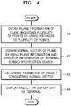
- FIG. 4 is a flowchart of an augmented reality providing method according to an embodiment of the present disclosure.
- the calculating unit 212 obtains the plane information of the plane including the plurality of points by using the distances to the plurality of points.
- the calculating unit 212 may further use the directions of the plurality of points.
- the calculating unit 212 obtains the normal vector of the plane by using the plane information obtained in step S41 and the direction information of the terminal measured by the direction sensor 222.
- the calculating unit 212 determines the parameter of the object considering the normal vector of the plane.
- the display control unit 213 displays the object on the display unit 230 of the terminal.
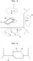
- FIG. 5 is a diagram for describing a method, performed by the augmented reality providing apparatus 200 of FIG. 2 , of recognizing a plane.
- the user terminal 20 is provided on a 3-dimensional (3D) space and a method in which and the 3D space is recognized by the augmented reality providing apparatus 200 provided in the user terminal 20 is illustrated. While the user terminal 20 freely changes a direction, the augmented reality providing apparatus 200 provided in the user terminal 20 may recognize a plurality of planes and recognize a space including the plurality of planes.
- FIG. 5 illustrates a first plane P1, a second plane P2, and a third plane P3.
- the augmented reality providing apparatus 200 recognizes the third plane P3 while the user terminal 20 faces the floor.
- a distance sensor provided at a rear surface of the user terminal 20 measures distances to and directions of a plurality of points S1 through S4.
- the augmented reality providing apparatus 200 combines information of the distances to and directions of the plurality of points S1 through S4 to define the third plane P3 including all of the plurality of points S1 through S4 and obtain direction information of the third plane P3.
- the direction information may be expressed in a plane equation or a plane vector, but is not limited thereto, and may be any information capable of defining a plane on a space.
- the direction information of the third plane P3 obtained based on the information of the distances to and directions of the plurality of points S1 through S4 measured based on the user terminal 20 is based on a direction in which the user terminal 20 faces. Accordingly, when the direction information of the third plane P3 is converted considering ground surface-based terminal direction information measured by a direction sensor provided in the user terminal 20, a third normal vector N3 with respect to the third plane P3 based on a ground surface may be obtained.
- a value of the third normal vector N3 of the third plane P3 based on the ground surface (or a gravity direction) may be obtained by adding direction information of the user terminal 20 based on the ground surface (or the gravity direction) to direction information of the third plane P3 based on a direction of the user terminal 20.
- the direction sensor may be an acceleration sensor recognizing gravitational acceleration, but is not limited thereto, and may be a 3-axis, 6-axis, or 9-axis sensor in which one or more of the acceleration sensor and a gyro sensor are combined.
- a first normal vector N1 with respect to the first plane P1 and a second normal vector N2 with respect to the second plane P2 may be further obtained by changing the direction of the user terminal 20 in the same method described above.
- the calculating unit 212 of the augmented reality providing apparatus 200 determines an attribute of each plane according to a normal vector of each plane. For example, vectors of a floor and ceiling and a vector of a floor may be pre-stored in the user terminal 20.
- vector ranges of the floor and the ceiling may be -5° to 5° and/or 175° to 185°
- a vector range of the wall may be 85° to 95° and/or 265° to 275°
- the first normal vector N1 and the third normal vector N3 correspond to the vector ranges of the floor and ceiling
- the second normal vector N2 corresponds to the vector range of the wall.
- the augmented reality providing apparatus 200 determines an attribute of the first plane P1 or third plane P3 as the floor or the ceiling, and an attribute of the second plane P2 as the wall.
- the vectors of the floor and the ceiling may each be defined as 0° or 180°, and the vector of the wall may be defined as 90° or 270°.
- the calculating unit 212 may define the attribute of the plane as the "floor or ceiling", and when the normal vector of the plane is the same as the vector of the wall within the error range, the calculating unit 212 may determine the attribute of the plane as the "wall".
- the calculating unit 212 may perform a vector inner product calculation to calculate similarity between a normal vector of a plane and a vector of a pre-set specific attribute so as to determine an attribute of the plane. As such, by calculating an inner product value of the vector instead of calculating a distance between vectors to be used to measure similarity, a calculation time may be remarkably reduced.
- the inner product value approaches 1 or -1 when the vectors are similar. For example, when an absolute value of an inner product of the second normal vector N2 of the second plane P2 and a pre-set vector of a "wall" attribute is within a pre-set error range at 1 to -1, the calculating unit 212 determines the attribute of the second plane P2 as the "wall".
- the augmented reality providing apparatus 200 may consider height information of each plane or the direction information of the user terminal 20 to determine each of the attributes of the first plane P1 and the third plane P3 to be one of the floor and the ceiling.
- the ceiling and the floor may be distinguished by comparing a height of the user terminal 20 and the height information of each plane distinguished according to the direction information of each plane and the direction information of the user terminal 20.
- the attribute of the first plane P1 of which the height is higher than the user terminal 20 is determined to be the ceiling
- the attribute of the third plane P3 of which the height is lower than the user terminal 20 is determined to be the floor.
- the augmented reality providing apparatus 200 may recognize a cross line e2 of the second plane P2 and the third plane P3 as the edge of the second plane P2 and the third plane P3 by referring to the second and third normal vectors N2 and N3 of the second plane P2 and the third plane P3.
- the augmented reality providing apparatus 200 may recognize the 3D space by using the first through third normal vectors N1 through N3.
- the augmented reality providing apparatus 200 may recognize a closed space. In order to complete the closed space, the augmented reality providing apparatus 200 may induce a photographing direction of the user terminal 20 by using a game element. For example, when there is a plane not surrounded by an edge, the augmented reality providing apparatus 200 may display, on the display unit 230 of the user terminal 20, an arrow or the like indicating a portion of the plane, which is not surrounded by an edge, or may apply an animation of moving a character displayed on the display unit 230 of the user terminal 20 to the portion not surrounded by an edge.
- the augmented reality providing apparatus 200 may display an object on a plane. For example, a character moving on the third plane P3 recognized as the floor may be displayed. The augmented reality providing apparatus 200 may set the character to move along a path between the plurality of points S1 through S4 recognized by the distance sensor, when the character moves on the third plane P3.
- an object 60 is placed on the third plane P3 recognized as the floor, and the augmented reality providing apparatus 200 may recognize a top surface of the object 60 as a sixth plane P6. Attributes of the third plane P3 and the sixth plane P6 may all be the "floor". As such, when a plurality of planes having the same attribute are present, the augmented reality providing apparatus 200 may provide an object moving between the plurality of planes and may apply an animation when the object moves. For example, a "jump" animation may be applied when an object is a character and the character moves between two planes (the third and sixth planes P3 and P6) having different heights.
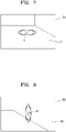
- FIGS. 7 and 8 are examples of screens in which augmented reality is provided.
- a screen captured by the camera 223 is displayed on a screen 80, and augmented reality is provided as an object i2 is overlapped and displayed on a plane 81.
- a parameter of the object i2 may include a color and inclination.
- the color of the object i2 may be a color corresponding to the "wall" that is an attribute of the plane 81, and the inclination of the object i2 may be set according to direction information of the plane 81.
- the object i2 is inclined and displayed in an oval shape according to a direction of the plane 81.
- the user may recognize an attribute of a plane where an object is displayed based on a color of the object and intuitively recognize a direction of the plane based on inclination of the object.
- FIGS. 9A through 9C are other examples of a screen in which augmented reality is provided.
- a screen captured by the camera 223 is displayed on a screen 90 and augmented reality is provided as an object i3 is overlapped and displayed on a plane 91 recognized by the augmented reality providing apparatus 200.
- a parameter of the object i3 may include character display information.
- the augmented reality providing apparatus 200 overlaps an opaque virtual layer 92 on the plane 91 and displays an animation as if the object i3 breaks through the plane 91 by displaying the object i3 to move in a normal vector direction of the plane 91, i.e., to move from the rear to the front of the virtual layer 92.
- the virtual layer 92 may be set to be displayed transparent with respect to the display other than the object i3. In other words, the virtual layer 92 may hide the display of the object i3 according to a position of the object i3, but is set not to hide the other display of the plane 91 or the like.
- FIG. 9A illustrates an example in which the object i3 is present behind the virtual layer 92 and thus is not displayed on the screen 90.
- FIG. 9B illustrates a screen in which the object i3 is moving from the rear to the front and illustrates an example in which a part of the object i3 is displayed on the plane 91 and the remaining part is not displayed on the screen 90.
- FIG. 9C illustrates an example in which the object i3 moved to the front of the virtual layer 92 and an entire view of the object i3 is overlapped and displayed on the plane 91.
- the object i3 may be a 3D object, and since the object i3 moves towards the user terminal 20 in the examples of FIGS. 9A through 9C , the augmented reality providing apparatus 200 may gradually increase the size of the object i3 as the object i3 moves.
- FIG. 10 is another example of a screen in which augmented reality is provided.
- a screen captured by the camera 223 is displayed on a screen 100, and augmented reality is provided as an object i4 is overlapped and displayed on a plane 101 recognized by the augmented reality providing apparatus 200.
- the augmented reality providing apparatus 200 may display the object i4 of "mirror" on the plane 101 of which an attribute is assigned as the "wall".
- the augmented reality providing apparatus 200 may indicate that the object i4 is a mirror by displaying a screen captured by a front camera (not shown) provided in the user terminal 20 in a pre-set internal region of the object i4.
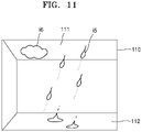
- FIG. 11 is another example of a screen in which augmented reality is provided.
- a screen captured by the camera 223 is displayed on a screen 110, and augmented reality is provided as an object i5 is overlapped and displayed on the screen 110 according to information of planes 111 and 112 recognized by the augmented reality providing apparatus 200.
- the augmented reality providing apparatus 200 may display the object i5 moving from the plane 111 of which an attribute is assigned as the "ceiling" to the plane 112 of which an attribute is assigned as the "floor”. Arrows shown in FIG. 11 indicate paths in which a plurality of elements (raindrops) included in the object i5 are moving for convenience of description and are not displayed on the screen 110.
- an animation in which elements of the object i5 move from the plane 111 to the plane 112, scatter in a same direction as the plane 112 when reaching the plane 112, and then disappear via fade-out, may be displayed to realize a display effect as if the raindrops are scattered on the floor.
- the augmented reality providing apparatus 200 may further overlap and display an object i6 on the plane 111 of which the attribute is assigned as the "ceiling". As shown in FIG. 11 , the augmented reality providing apparatus 200 may display a plurality of objects together.
- a virtual layer described above may be displayed on the plane 111, and the elements of the object i5 may be displayed to move from the rear to the front of the virtual layer corresponding to the plane 111.
- the elements of the object i5 may be displayed to move from the rear to the front of the object i6.
- the object i6 may be set to be opaque with respect to the object i5, and moreover, may be set to be opaque with respect to not only the object i5, but also other portions displayed on the screen 110, for example, the plane 111.
- the augmented reality providing method according to an embodiment of the present disclosure shown in FIG. 4 can be written as a computer-executable program and can be implemented in general-use digital computers that execute the program using a computer-readable recording medium.
- the medium may continuously store a computer-executable program or may temporarily store the computer-executable program to be executed or downloaded.
- the medium may be various recording means or storage means of single hardware or a combination of plurality of pieces of hardware, and is not limited to a medium directly accessing a computer program, but may be distributed on a network.
- Examples of the medium include magnetic media, such as a hard disk, a floppy disk, and a magnetic tape, optical recording media, such as CD-ROM and DVD, magneto-optical media such as a floptical disk, and ROM, RAM, and a flash memory, which are configured to store program instructions.
- other examples of the medium include recording media or storage media managed by an application store distributing applications, a website or server supplying or distributing other various types of software, and the like.
- the present disclosure is applicable to various fields capable of using augmented reality.
- the present disclosure is applicable to various fields, such as games, broadcasting, architectural designs, vehicles, interior designs, manufacturing process management, mobile solutions, and education.
Landscapes
- Engineering & Computer Science (AREA)
- Physics & Mathematics (AREA)
- General Physics & Mathematics (AREA)
- Theoretical Computer Science (AREA)
- General Engineering & Computer Science (AREA)
- Radar, Positioning & Navigation (AREA)
- Remote Sensing (AREA)
- Electromagnetism (AREA)
- Computer Networks & Wireless Communication (AREA)
- Human Computer Interaction (AREA)
- Computer Vision & Pattern Recognition (AREA)
- Software Systems (AREA)
- Computer Hardware Design (AREA)
- Computer Graphics (AREA)
- Optics & Photonics (AREA)
- User Interface Of Digital Computer (AREA)
- Processing Or Creating Images (AREA)
Claims (14)
- Computerprogramm, das auf einem computerlesbaren Aufzeichnungsmedium gespeichert ist, um ein Verfahren zum Bereitstellen erweiterter Realität (augmented reality) unter Verwendung eines Computers auszuführen, wobei das Verfahren zum Bereitstellen erweiterter Realität umfasst:Ermitteln (41) von Ebenen-Informationen einer Ebene (P1 - P3), die eine Vielzahl von Punkten (S1 - S4) einschließt, unter Verwendung von Abständen von einem Abstands-Sensor (221) zu der Vielzahl von Punkten (S1 - S4), wobei die Abstände von dem in einem Endgerät (20) vorhandenen Abstands-Sensor (221) gemessen werden;Ermitteln (42) eines Normalenvektors (N1 - N3) der Ebene (P1 - P3) unter Verwendung der Ebenen-Informationen und durch einen Richtungs-Sensor (222) gemessener Informationen des Endgerätes (20);Bestimmen (43) eines Parameters eines auf der Ebene (P1 - P3) anzuzeigenden Objektes unter Berücksichtigung des Normalenvektors (N1 - N3), wobei der Parameter eine Größe des Objektes, eine Richtung des Objektes, eine Farbe des Objektes oder/und eine auf das Objekt angewendete Animation umfasst; undAnzeigen (44) des Objektes auf einer Anzeige-Einheit (230) des Endgerätes (20) entsprechend dem bestimmten Parameter.
- Computerprogramm nach Anspruch 1, wobei das Verfahren zum Bereitstellen erweiterter Realität des Weiteren Ermitteln der Abstände zu und Richtungen der Vielzahl von Punkten von einem Infrarot-Sensor umfasst, wobei der Abstands-Sensor den Infrarot-Sensor umfasst, und
das Ermitteln der Ebenen-Informationen Ermitteln der Ebenen-Informationen unter Verwendung der gemessenen Abstände und Richtungen umfasst. - Computerprogramm nach Anspruch 1, wobei die Ebenen-Informationen Richtungs-Informationen der Ebene sind, die auf einer Richtung des Endgerätes basieren, und der Richtungs-Sensor einen Beschleunigungs-Sensor oder/und einen Gyro-Sensor einschließt, und
das Ermitteln des Normalenvektors Ermitteln des Normalenvektors durch Umwandeln einer Bezugsgröße der Richtungs-Informationen der Ebene aus der Richtung des Endgerätes in eine Bezugs-Richtung des Richtungs-Sensors auf Basis der gemessenen Richtungs-Informationen des Endgerätes umfasst. - Computerprogramm nach Anspruch 1, wobei das Bestimmen Bestimmen eines Attributs der Ebene auf der Grundlage des Normalenvektors sowie Bestimmen des Parameters unter Berücksichtigung des bestimmten Attributs umfasst.
- Computerprogramm nach Anspruch 4, wobei die Ebenen-Informationen Richtungs-Informationen der Ebene sind und das Bestimmen Bestimmen eines ersten Parameters des Objektes auf Basis des Attributs sowie Bestimmen eines zweiten Parameters des Objektes auf Basis der Richtungs-Informationen der Ebene umfasst, oder
die Ebenen-Informationen Richtungs-Informationen der Ebene sind, das Bestimmen Bestimmen eines Typs des Objektes auf Basis des Attributs sowie Bestimmen einer Rendering-Richtung des Objektes auf Basis der Richtungs-Informationen der Ebene umfasst, und das Anzeigen zweidimensionales Rendering dreidimensionaler Informationen zum Anzeigen des Objektes gemäß der Rendering-Richtung sowie zweidimensionales Anzeigen des Objektes umfasst. - Computerprogramm nach Anspruch 1, wobei das Anzeigen Überlagern des Objektes und eines von einer in dem Endgerät vorhandenen Kamera aufgenommenen Videos sowie Anzeigen des von dem Objekt überlagerten Videos umfasst.
- Computerprogramm nach Anspruch 6, wobei
die Kamera und der Abstands-Sensor in ein und dieselbe Richtung gewandt sind. - Verfahren zum Bereitstellen erweiterter Realität, das umfasst:Ermitteln (41) von Ebenen-Informationen einer Ebene, die eine Vielzahl von Punkten einschließt, unter Verwendung von Abständen von einem Abstands-Sensor (221) zu der Vielzahl von Punkten, wobei die Abstände von dem in einem Endgerät vorhandenen Abstands-Sensor (221) gemessen werden;Ermitteln (42) eines Normalenvektors der Ebene unter Verwendung der Ebenen-Informationen und durch einen Richtungs-Sensor gemessener Richtungs-Informationen des Endgerätes;Bestimmen (43) eines Parameters eines auf der Ebene anzuzeigenden Objektes unter Berücksichtigung des Normalenvektors, wobei der Parameter eine Größe des Objektes, einer Richtung des Objektes, eine Farbe des Objektes oder/und eine auf das Objekt angewendete Animation umfasst; undAnzeigen (44) des Objektes gemäß dem bestimmten Parameter auf einer Anzeige-Einheit des Endgerätes.
- Vorrichtung (200) zum Bereitstellen erweiterter Realität, die umfasst:eine Einheit (211) zum Ermitteln von Signalen, die so ausgeführt ist, dass sie Abstände von einem Abstands-Sensor (221) zu einer Vielzahl von Punkten (S1 - S4), die von dem Abstands-Sensor gemessen werden, und Richtungs-Informationen eines Endgerätes (20) ermittelt, die von einem Richtungs-Sensor (222) gemessen werden;eine Berechnungs-Einheit (212), die so ausgeführt ist, dass sie Ebenen-Informationen einer Ebene (P1 - P3), die die Vielzahl von Punkten (S1 - S4) einschließt, unter Verwendung der Abstände ermittelt, einen Normalenvektor (N1 - N3) der Ebene (P1 - P3) unter Verwendung der Richtungs-Informationen des Endgerätes (20) sowie der Ebenen-Informationen ermittelt und einen Parameter eines auf der Ebene (P1 - P3) anzuzeigenden Objektes, unter Berücksichtigung des Normalenvektors (N1 - N3) bestimmt, wobei der Parameter eine Größe des Objektes, eine Richtung des Objektes, eine Farbe des Objektes oder eine auf das Objekt angewendete Animation umfasst; sowieeine Anzeige-Steuerungseinheit (213), die so ausgeführt ist, dass sie das Objekt gemäß dem bestimmten Parameter auf einer Anzeige-Einheit des Endgerätes (20) anzeigt.
- Vorrichtung zum Bereitstellen erweiterter Realität nach Anspruch 9, die des Weiteren den Richtungs-Sensor umfasst, der einen Beschleunigungs-Sensor oder/und einen Gyro-Sensor umfasst, wobei die Ebenen-Informationen Richtungs-Informationen der Ebene sind, die auf einer Richtung des Endgerätes basieren, und die Berechnungs-Einheit den Normalvektor durch Umwandeln einer Bezugsgröße der Richtungs-Informationen der Ebene aus der Richtung des Endgerätes in eine Bezugs-Richtung des Richtungs-Sensors auf Basis der gemessenen Richtungs-Informationen des Endgerätes ermittelt.
- Vorrichtung zum Bereitstellen erweiterter Realität nach Anspruch 9, wobei die Berechnungs-Einheit ein Attribut der Ebene auf Basis des Normalenvektors bestimmt und den Parameter unter Berücksichtigung des bestimmten Attributs bestimmt.
- Vorrichtung zum Bereitstellen erweiterter Realität nach Anspruch 11, wobei die Ebenen-Informationen Richtungs-Informationen der Ebene sind und die Berechnungs-Einheit einen ersten Parameter des Objektes auf Basis des Attributs bestimmt und einen zweiten Parameter des Objektes auf Basis der Richtungs-Informationen der Ebene bestimmt, oder
die Ebenen-Informationen Richtungs-Informationen der Ebene sind, die Berechnungs-Einheit einen Typ des Objektes auf Basis des Attributs bestimmt und eine Rendering-Richtung des Objektes auf Basis der Richtungs-Informationen der Ebene umfasst, und die Anzeige-Steuerungseinheit dreidimensionale Informationen zum Anzeigen des Objektes entsprechend der Rendering-Richtung zweidimensional rendert und dreidimensionale Informationen zum Anzeigen des Objektes zweidimensional anzeigt. - Vorrichtung zum Bereitstellen erweiterter Realität nach Anspruch 9, wobei die Anzeige-Steuerungseinheit das Objekt und ein von einer in dem Endgerät vorhandenen Kamera aufgenommenes Video überlagert und das von dem Objekt überlagerte Video anzeigt.
- Vorrichtung zum Bereitstellen erweiterter Realität nach Anspruch 13, die des Weiteren umfasst:die Kamera; sowieden Abstands-Sensor,wobei die Kamera und der Abstands-Sensor in ein und dieselbe Richtung gewandt sind.
Applications Claiming Priority (1)
| Application Number | Priority Date | Filing Date | Title |
|---|---|---|---|
| PCT/KR2017/002373 WO2018164287A1 (ko) | 2017-03-06 | 2017-03-06 | 증강현실 제공 방법, 장치 및 컴퓨터 프로그램 |
Publications (3)
| Publication Number | Publication Date |
|---|---|
| EP3594906A1 EP3594906A1 (de) | 2020-01-15 |
| EP3594906A4 EP3594906A4 (de) | 2020-11-04 |
| EP3594906B1 true EP3594906B1 (de) | 2022-10-19 |
Family
ID=63448162
Family Applications (1)
| Application Number | Title | Priority Date | Filing Date |
|---|---|---|---|
| EP17899941.3A Active EP3594906B1 (de) | 2017-03-06 | 2017-03-06 | Verfahren und vorrichtung zur bereitstellung einer erweiterten realität und computerprogramm |
Country Status (5)
| Country | Link |
|---|---|
| US (2) | US11120629B2 (de) |
| EP (1) | EP3594906B1 (de) |
| JP (1) | JP6980802B2 (de) |
| CN (2) | CN110313021B (de) |
| WO (1) | WO2018164287A1 (de) |
Families Citing this family (3)
| Publication number | Priority date | Publication date | Assignee | Title |
|---|---|---|---|---|
| CN110930488B (zh) * | 2019-11-15 | 2023-06-06 | 深圳市瑞立视多媒体科技有限公司 | 鱼体行为模拟方法、装置、设备及存储介质 |
| CN111582418B (zh) * | 2020-05-20 | 2022-03-08 | 郝杰 | 一种ar虚拟说明书的滑动展示方法 |
| KR20210158695A (ko) * | 2020-06-24 | 2021-12-31 | 삼성전자주식회사 | 영상에서 평면을 검출하는 전자 장치 및 그 동작 방법 |
Family Cites Families (26)
| Publication number | Priority date | Publication date | Assignee | Title |
|---|---|---|---|---|
| JPH0518940A (ja) * | 1991-07-09 | 1993-01-26 | Aloka Co Ltd | 超音波三次元画像表示装置 |
| JPH0998323A (ja) * | 1995-09-29 | 1997-04-08 | Matsushita Electric Ind Co Ltd | ビデオカメラ |
| JP2004192653A (ja) * | 1997-02-28 | 2004-07-08 | Toshiba Corp | マルチモーダルインタフェース装置およびマルチモーダルインタフェース方法 |
| JP2002366976A (ja) * | 2001-06-08 | 2002-12-20 | Fujitsu Ltd | オブジェクト表示プログラムおよびオブジェクト表示装置 |
| US8970690B2 (en) * | 2009-02-13 | 2015-03-03 | Metaio Gmbh | Methods and systems for determining the pose of a camera with respect to at least one object of a real environment |
| JP5232911B2 (ja) * | 2009-03-26 | 2013-07-10 | 京セラ株式会社 | 携帯電子機器 |
| KR100982768B1 (ko) * | 2009-09-21 | 2010-09-20 | (주)올라웍스 | 단말기의 각도에 따라 서로 다른 영상 정보를 제공하기 위한 방법, 단말기 및 컴퓨터 판독 가능한 기록 매체 |
| US8963954B2 (en) * | 2010-06-30 | 2015-02-24 | Nokia Corporation | Methods, apparatuses and computer program products for providing a constant level of information in augmented reality |
| JP5799521B2 (ja) * | 2011-02-15 | 2015-10-28 | ソニー株式会社 | 情報処理装置、オーサリング方法及びプログラム |
| JP5724543B2 (ja) * | 2011-03-31 | 2015-05-27 | ソニー株式会社 | 端末装置、オブジェクト制御方法及びプログラム |
| KR101971948B1 (ko) * | 2011-07-28 | 2019-04-24 | 삼성전자주식회사 | 평면 특성 기반 마커리스 증강 현실 시스템 및 그 동작 방법 |
| EP2750110B1 (de) * | 2011-08-24 | 2020-03-18 | Sony Corporation | Informationsverarbeitungsvorrichtung, informationsverarbeitungsverfahren und programm |
| KR101837107B1 (ko) * | 2011-09-01 | 2018-03-09 | 에스케이 텔레콤주식회사 | 증강 현실을 이용하여 실내 위치 기반 서비스를 제공하는 단말기 및 컴퓨터로 읽을 수 있는 기록매체 |
| JP2013225245A (ja) * | 2012-04-23 | 2013-10-31 | Sony Corp | 画像処理装置、画像処理方法及びプログラム |
| KR101546654B1 (ko) * | 2012-06-26 | 2015-08-25 | 한국과학기술원 | 웨어러블 증강현실 환경에서 증강현실 서비스 제공 방법 및 장치 |
| US9317972B2 (en) * | 2012-12-18 | 2016-04-19 | Qualcomm Incorporated | User interface for augmented reality enabled devices |
| KR20140145217A (ko) * | 2013-05-30 | 2014-12-23 | (주)브이알엑스 | 공간정보를 이용한 3차원 가상 모델링 시스템 및 그 방법 |
| US9432636B2 (en) * | 2013-11-26 | 2016-08-30 | Microsoft Technology Licensing, Llc | Large-scale surface reconstruction that is robust against tracking and mapping errors |
| WO2015092905A1 (ja) * | 2013-12-19 | 2015-06-25 | 日立マクセル株式会社 | 投写型映像表示装置及び投写型映像表示方法 |
| US9953111B2 (en) * | 2014-06-06 | 2018-04-24 | Matterport, Inc. | Semantic understanding of 3D data |
| US10659750B2 (en) * | 2014-07-23 | 2020-05-19 | Apple Inc. | Method and system for presenting at least part of an image of a real object in a view of a real environment, and method and system for selecting a subset of a plurality of images |
| US20160191877A1 (en) * | 2014-12-25 | 2016-06-30 | Panasonic Intellectual Property Management Co., Ltd. | Projector device and projection method |
| JP2016139199A (ja) * | 2015-01-26 | 2016-08-04 | 株式会社リコー | 画像処理装置、画像処理方法、およびプログラム |
| JP6723798B2 (ja) * | 2015-05-20 | 2020-07-15 | キヤノン株式会社 | 情報処理装置、方法、プログラム |
| KR20170014451A (ko) * | 2015-07-30 | 2017-02-08 | 삼성에스디에스 주식회사 | 시야 확보 시스템, 방법 및 이를 수행하기 위한 단말 |
| US9858683B2 (en) * | 2015-08-05 | 2018-01-02 | Intel Corporation | Method and system of planar surface detection objects in 3d space generated from captured images for image processing |
-
2017
- 2017-03-06 CN CN201780086884.9A patent/CN110313021B/zh active Active
- 2017-03-06 JP JP2019548040A patent/JP6980802B2/ja active Active
- 2017-03-06 EP EP17899941.3A patent/EP3594906B1/de active Active
- 2017-03-06 WO PCT/KR2017/002373 patent/WO2018164287A1/ko unknown
- 2017-03-06 CN CN202310837824.3A patent/CN116863107A/zh active Pending
-
2019
- 2019-07-11 US US16/508,830 patent/US11120629B2/en active Active
-
2021
- 2021-08-05 US US17/395,083 patent/US11562545B2/en active Active
Also Published As
| Publication number | Publication date |
|---|---|
| CN110313021A (zh) | 2019-10-08 |
| WO2018164287A1 (ko) | 2018-09-13 |
| JP6980802B2 (ja) | 2021-12-15 |
| US11120629B2 (en) | 2021-09-14 |
| US20190333282A1 (en) | 2019-10-31 |
| CN116863107A (zh) | 2023-10-10 |
| JP2020509505A (ja) | 2020-03-26 |
| EP3594906A4 (de) | 2020-11-04 |
| CN110313021B (zh) | 2023-07-25 |
| US11562545B2 (en) | 2023-01-24 |
| EP3594906A1 (de) | 2020-01-15 |
| US20210366199A1 (en) | 2021-11-25 |
Similar Documents
| Publication | Publication Date | Title |
|---|---|---|
| KR101993920B1 (ko) | 물리적 장면을 표현하기 위한 방법 및 장치 | |
| US9898844B2 (en) | Augmented reality content adapted to changes in real world space geometry | |
| JP5877219B2 (ja) | 動き特性を使用することによるディスプレイへの三次元ユーザインターフェイス効果 | |
| US11263457B2 (en) | Virtual item display simulations | |
| US20170205985A1 (en) | Expanding a 3d stack of floor maps at a rate proportional to a speed of a pinch gesture | |
| US9443353B2 (en) | Methods and systems for capturing and moving 3D models and true-scale metadata of real world objects | |
| JP7008730B2 (ja) | 画像に挿入される画像コンテンツについての影生成 | |
| US11562545B2 (en) | Method and device for providing augmented reality, and computer program | |
| EP3814876B1 (de) | Platzierung und manipulation von gegenständen in einer erweiterten realitätsumgebung | |
| JP5592011B2 (ja) | マルチスケール3次元配向 | |
| CN112154405B (zh) | 三维推送通知 | |
| US20150185825A1 (en) | Assigning a virtual user interface to a physical object | |
| US20200211243A1 (en) | Image bounding shape using 3d environment representation | |
| CN115335894A (zh) | 用于虚拟和增强现实的系统和方法 | |
| US20230037750A1 (en) | Systems and methods for generating stabilized images of a real environment in artificial reality | |
| CA3128614A1 (en) | Method and system for displaying a large 3d model on a remote device | |
| WO2018090914A1 (zh) | 三维视觉效果模拟方法及装置、存储介质及显示设备 | |
| CN114663632A (zh) | 基于空间位置的光照显示虚拟物体的方法及设备 | |
| Trapp et al. | Strategies for visualising 3D points-of-interest on mobile devices | |
| US12002165B1 (en) | Light probe placement for displaying objects in 3D environments on electronic devices | |
| WO2022089061A1 (zh) | 物体标注信息呈现方法、装置、电子设备及存储介质 |
Legal Events
| Date | Code | Title | Description |
|---|---|---|---|
| STAA | Information on the status of an ep patent application or granted ep patent |
Free format text: STATUS: THE INTERNATIONAL PUBLICATION HAS BEEN MADE |
|
| PUAI | Public reference made under article 153(3) epc to a published international application that has entered the european phase |
Free format text: ORIGINAL CODE: 0009012 |
|
| STAA | Information on the status of an ep patent application or granted ep patent |
Free format text: STATUS: REQUEST FOR EXAMINATION WAS MADE |
|
| 17P | Request for examination filed |
Effective date: 20190830 |
|
| AK | Designated contracting states |
Kind code of ref document: A1 Designated state(s): AL AT BE BG CH CY CZ DE DK EE ES FI FR GB GR HR HU IE IS IT LI LT LU LV MC MK MT NL NO PL PT RO RS SE SI SK SM TR |
|
| AX | Request for extension of the european patent |
Extension state: BA ME |
|
| DAV | Request for validation of the european patent (deleted) | ||
| DAX | Request for extension of the european patent (deleted) | ||
| A4 | Supplementary search report drawn up and despatched |
Effective date: 20201001 |
|
| RIC1 | Information provided on ipc code assigned before grant |
Ipc: G06T 19/00 20110101ALI20200928BHEP Ipc: G01S 17/42 20060101ALI20200928BHEP Ipc: G01S 7/48 20060101AFI20200928BHEP Ipc: G06T 7/30 20170101ALI20200928BHEP Ipc: G01S 17/86 20200101ALI20200928BHEP Ipc: G06F 3/01 20060101ALI20200928BHEP Ipc: G06F 3/0346 20130101ALI20200928BHEP Ipc: G06T 7/521 20170101ALI20200928BHEP Ipc: G01S 15/08 20060101ALI20200928BHEP Ipc: G06T 7/70 20170101ALI20200928BHEP |
|
| RAP1 | Party data changed (applicant data changed or rights of an application transferred) |
Owner name: LINE CORPORATION |
|
| REG | Reference to a national code |
Ref country code: DE Ref legal event code: R079 Ref document number: 602017062895 Country of ref document: DE Free format text: PREVIOUS MAIN CLASS: G06T0019000000 Ipc: G01S0007480000 |
|
| GRAP | Despatch of communication of intention to grant a patent |
Free format text: ORIGINAL CODE: EPIDOSNIGR1 |
|
| STAA | Information on the status of an ep patent application or granted ep patent |
Free format text: STATUS: GRANT OF PATENT IS INTENDED |
|
| RIC1 | Information provided on ipc code assigned before grant |
Ipc: G06T 7/73 20170101ALI20220414BHEP Ipc: G01S 17/86 20200101ALI20220414BHEP Ipc: G01S 15/08 20060101ALI20220414BHEP Ipc: G01S 17/42 20060101ALI20220414BHEP Ipc: G06F 3/01 20060101ALI20220414BHEP Ipc: G06F 3/0346 20130101ALI20220414BHEP Ipc: G06T 7/70 20170101ALI20220414BHEP Ipc: G06T 7/521 20170101ALI20220414BHEP Ipc: G06T 7/30 20170101ALI20220414BHEP Ipc: G06T 19/00 20110101ALI20220414BHEP Ipc: G01S 7/48 20060101AFI20220414BHEP |
|
| INTG | Intention to grant announced |
Effective date: 20220502 |
|
| GRAS | Grant fee paid |
Free format text: ORIGINAL CODE: EPIDOSNIGR3 |
|
| GRAA | (expected) grant |
Free format text: ORIGINAL CODE: 0009210 |
|
| STAA | Information on the status of an ep patent application or granted ep patent |
Free format text: STATUS: THE PATENT HAS BEEN GRANTED |
|
| AK | Designated contracting states |
Kind code of ref document: B1 Designated state(s): AL AT BE BG CH CY CZ DE DK EE ES FI FR GB GR HR HU IE IS IT LI LT LU LV MC MK MT NL NO PL PT RO RS SE SI SK SM TR |
|
| REG | Reference to a national code |
Ref country code: GB Ref legal event code: FG4D |
|
| REG | Reference to a national code |
Ref country code: CH Ref legal event code: EP |
|
| REG | Reference to a national code |
Ref country code: IE Ref legal event code: FG4D |
|
| REG | Reference to a national code |
Ref country code: DE Ref legal event code: R096 Ref document number: 602017062895 Country of ref document: DE |
|
| REG | Reference to a national code |
Ref country code: AT Ref legal event code: REF Ref document number: 1525887 Country of ref document: AT Kind code of ref document: T Effective date: 20221115 |
|
| REG | Reference to a national code |
Ref country code: LT Ref legal event code: MG9D |
|
| REG | Reference to a national code |
Ref country code: NL Ref legal event code: MP Effective date: 20221019 |
|
| REG | Reference to a national code |
Ref country code: AT Ref legal event code: MK05 Ref document number: 1525887 Country of ref document: AT Kind code of ref document: T Effective date: 20221019 |
|
| PG25 | Lapsed in a contracting state [announced via postgrant information from national office to epo] |
Ref country code: NL Free format text: LAPSE BECAUSE OF FAILURE TO SUBMIT A TRANSLATION OF THE DESCRIPTION OR TO PAY THE FEE WITHIN THE PRESCRIBED TIME-LIMIT Effective date: 20221019 |
|
| PG25 | Lapsed in a contracting state [announced via postgrant information from national office to epo] |
Ref country code: SE Free format text: LAPSE BECAUSE OF FAILURE TO SUBMIT A TRANSLATION OF THE DESCRIPTION OR TO PAY THE FEE WITHIN THE PRESCRIBED TIME-LIMIT Effective date: 20221019 Ref country code: PT Free format text: LAPSE BECAUSE OF FAILURE TO SUBMIT A TRANSLATION OF THE DESCRIPTION OR TO PAY THE FEE WITHIN THE PRESCRIBED TIME-LIMIT Effective date: 20230220 Ref country code: NO Free format text: LAPSE BECAUSE OF FAILURE TO SUBMIT A TRANSLATION OF THE DESCRIPTION OR TO PAY THE FEE WITHIN THE PRESCRIBED TIME-LIMIT Effective date: 20230119 Ref country code: LT Free format text: LAPSE BECAUSE OF FAILURE TO SUBMIT A TRANSLATION OF THE DESCRIPTION OR TO PAY THE FEE WITHIN THE PRESCRIBED TIME-LIMIT Effective date: 20221019 Ref country code: FI Free format text: LAPSE BECAUSE OF FAILURE TO SUBMIT A TRANSLATION OF THE DESCRIPTION OR TO PAY THE FEE WITHIN THE PRESCRIBED TIME-LIMIT Effective date: 20221019 Ref country code: ES Free format text: LAPSE BECAUSE OF FAILURE TO SUBMIT A TRANSLATION OF THE DESCRIPTION OR TO PAY THE FEE WITHIN THE PRESCRIBED TIME-LIMIT Effective date: 20221019 Ref country code: AT Free format text: LAPSE BECAUSE OF FAILURE TO SUBMIT A TRANSLATION OF THE DESCRIPTION OR TO PAY THE FEE WITHIN THE PRESCRIBED TIME-LIMIT Effective date: 20221019 |
|
| PG25 | Lapsed in a contracting state [announced via postgrant information from national office to epo] |
Ref country code: RS Free format text: LAPSE BECAUSE OF FAILURE TO SUBMIT A TRANSLATION OF THE DESCRIPTION OR TO PAY THE FEE WITHIN THE PRESCRIBED TIME-LIMIT Effective date: 20221019 Ref country code: PL Free format text: LAPSE BECAUSE OF FAILURE TO SUBMIT A TRANSLATION OF THE DESCRIPTION OR TO PAY THE FEE WITHIN THE PRESCRIBED TIME-LIMIT Effective date: 20221019 Ref country code: LV Free format text: LAPSE BECAUSE OF FAILURE TO SUBMIT A TRANSLATION OF THE DESCRIPTION OR TO PAY THE FEE WITHIN THE PRESCRIBED TIME-LIMIT Effective date: 20221019 Ref country code: IS Free format text: LAPSE BECAUSE OF FAILURE TO SUBMIT A TRANSLATION OF THE DESCRIPTION OR TO PAY THE FEE WITHIN THE PRESCRIBED TIME-LIMIT Effective date: 20230219 Ref country code: HR Free format text: LAPSE BECAUSE OF FAILURE TO SUBMIT A TRANSLATION OF THE DESCRIPTION OR TO PAY THE FEE WITHIN THE PRESCRIBED TIME-LIMIT Effective date: 20221019 Ref country code: GR Free format text: LAPSE BECAUSE OF FAILURE TO SUBMIT A TRANSLATION OF THE DESCRIPTION OR TO PAY THE FEE WITHIN THE PRESCRIBED TIME-LIMIT Effective date: 20230120 |
|
| REG | Reference to a national code |
Ref country code: DE Ref legal event code: R097 Ref document number: 602017062895 Country of ref document: DE |
|
| PG25 | Lapsed in a contracting state [announced via postgrant information from national office to epo] |
Ref country code: SM Free format text: LAPSE BECAUSE OF FAILURE TO SUBMIT A TRANSLATION OF THE DESCRIPTION OR TO PAY THE FEE WITHIN THE PRESCRIBED TIME-LIMIT Effective date: 20221019 Ref country code: RO Free format text: LAPSE BECAUSE OF FAILURE TO SUBMIT A TRANSLATION OF THE DESCRIPTION OR TO PAY THE FEE WITHIN THE PRESCRIBED TIME-LIMIT Effective date: 20221019 Ref country code: EE Free format text: LAPSE BECAUSE OF FAILURE TO SUBMIT A TRANSLATION OF THE DESCRIPTION OR TO PAY THE FEE WITHIN THE PRESCRIBED TIME-LIMIT Effective date: 20221019 Ref country code: DK Free format text: LAPSE BECAUSE OF FAILURE TO SUBMIT A TRANSLATION OF THE DESCRIPTION OR TO PAY THE FEE WITHIN THE PRESCRIBED TIME-LIMIT Effective date: 20221019 Ref country code: CZ Free format text: LAPSE BECAUSE OF FAILURE TO SUBMIT A TRANSLATION OF THE DESCRIPTION OR TO PAY THE FEE WITHIN THE PRESCRIBED TIME-LIMIT Effective date: 20221019 |
|
| PLBE | No opposition filed within time limit |
Free format text: ORIGINAL CODE: 0009261 |
|
| STAA | Information on the status of an ep patent application or granted ep patent |
Free format text: STATUS: NO OPPOSITION FILED WITHIN TIME LIMIT |
|
| PG25 | Lapsed in a contracting state [announced via postgrant information from national office to epo] |
Ref country code: SK Free format text: LAPSE BECAUSE OF FAILURE TO SUBMIT A TRANSLATION OF THE DESCRIPTION OR TO PAY THE FEE WITHIN THE PRESCRIBED TIME-LIMIT Effective date: 20221019 Ref country code: AL Free format text: LAPSE BECAUSE OF FAILURE TO SUBMIT A TRANSLATION OF THE DESCRIPTION OR TO PAY THE FEE WITHIN THE PRESCRIBED TIME-LIMIT Effective date: 20221019 |
|
| 26N | No opposition filed |
Effective date: 20230720 |
|
| PG25 | Lapsed in a contracting state [announced via postgrant information from national office to epo] |
Ref country code: MC Free format text: LAPSE BECAUSE OF FAILURE TO SUBMIT A TRANSLATION OF THE DESCRIPTION OR TO PAY THE FEE WITHIN THE PRESCRIBED TIME-LIMIT Effective date: 20221019 |
|
| REG | Reference to a national code |
Ref country code: CH Ref legal event code: PL |
|
| PG25 | Lapsed in a contracting state [announced via postgrant information from national office to epo] |
Ref country code: SI Free format text: LAPSE BECAUSE OF FAILURE TO SUBMIT A TRANSLATION OF THE DESCRIPTION OR TO PAY THE FEE WITHIN THE PRESCRIBED TIME-LIMIT Effective date: 20221019 |
|
| REG | Reference to a national code |
Ref country code: BE Ref legal event code: MM Effective date: 20230331 |
|
| PG25 | Lapsed in a contracting state [announced via postgrant information from national office to epo] |
Ref country code: LU Free format text: LAPSE BECAUSE OF NON-PAYMENT OF DUE FEES Effective date: 20230306 |
|
| REG | Reference to a national code |
Ref country code: IE Ref legal event code: MM4A |
|
| PG25 | Lapsed in a contracting state [announced via postgrant information from national office to epo] |
Ref country code: LI Free format text: LAPSE BECAUSE OF NON-PAYMENT OF DUE FEES Effective date: 20230331 Ref country code: IE Free format text: LAPSE BECAUSE OF NON-PAYMENT OF DUE FEES Effective date: 20230306 Ref country code: CH Free format text: LAPSE BECAUSE OF NON-PAYMENT OF DUE FEES Effective date: 20230331 |
|
| PGFP | Annual fee paid to national office [announced via postgrant information from national office to epo] |
Ref country code: FR Payment date: 20231222 Year of fee payment: 8 |
|
| PG25 | Lapsed in a contracting state [announced via postgrant information from national office to epo] |
Ref country code: BE Free format text: LAPSE BECAUSE OF NON-PAYMENT OF DUE FEES Effective date: 20230331 |
|
| PGFP | Annual fee paid to national office [announced via postgrant information from national office to epo] |
Ref country code: DE Payment date: 20231220 Year of fee payment: 8 Ref country code: GB Payment date: 20240105 Year of fee payment: 8 |
|
| PG25 | Lapsed in a contracting state [announced via postgrant information from national office to epo] |
Ref country code: IT Free format text: LAPSE BECAUSE OF FAILURE TO SUBMIT A TRANSLATION OF THE DESCRIPTION OR TO PAY THE FEE WITHIN THE PRESCRIBED TIME-LIMIT Effective date: 20221019 |