EP3594775A1 - Bauteil mit einem bildelement und verfahren zur herstellung des bauteils - Google Patents
Bauteil mit einem bildelement und verfahren zur herstellung des bauteils Download PDFInfo
- Publication number
- EP3594775A1 EP3594775A1 EP19185010.6A EP19185010A EP3594775A1 EP 3594775 A1 EP3594775 A1 EP 3594775A1 EP 19185010 A EP19185010 A EP 19185010A EP 3594775 A1 EP3594775 A1 EP 3594775A1
- Authority
- EP
- European Patent Office
- Prior art keywords
- component
- opening
- adjacent
- tool part
- picture element
- Prior art date
- Legal status (The legal status is an assumption and is not a legal conclusion. Google has not performed a legal analysis and makes no representation as to the accuracy of the status listed.)
- Granted
Links
Images


Classifications
-
- G—PHYSICS
- G05—CONTROLLING; REGULATING
- G05G—CONTROL DEVICES OR SYSTEMS INSOFAR AS CHARACTERISED BY MECHANICAL FEATURES ONLY
- G05G1/00—Controlling members, e.g. knobs or handles; Assemblies or arrangements thereof; Indicating position of controlling members
- G05G1/08—Controlling members for hand actuation by rotary movement, e.g. hand wheels
- G05G1/10—Details, e.g. of discs, knobs, wheels or handles
- G05G1/105—Details, e.g. of discs, knobs, wheels or handles comprising arrangements for illumination
-
- G—PHYSICS
- G05—CONTROLLING; REGULATING
- G05G—CONTROL DEVICES OR SYSTEMS INSOFAR AS CHARACTERISED BY MECHANICAL FEATURES ONLY
- G05G1/00—Controlling members, e.g. knobs or handles; Assemblies or arrangements thereof; Indicating position of controlling members
- G05G1/30—Controlling members actuated by foot
- G05G1/50—Manufacturing of pedals; Pedals characterised by the material used
- G05G1/503—Controlling members for hand-actuation
-
- G—PHYSICS
- G09—EDUCATION; CRYPTOGRAPHY; DISPLAY; ADVERTISING; SEALS
- G09F—DISPLAYING; ADVERTISING; SIGNS; LABELS OR NAME-PLATES; SEALS
- G09F13/00—Illuminated signs; Luminous advertising
- G09F13/04—Signs, boards or panels, illuminated from behind the insignia
- G09F13/0409—Arrangements for homogeneous illumination of the display surface, e.g. using a layer having a non-uniform transparency
-
- G—PHYSICS
- G09—EDUCATION; CRYPTOGRAPHY; DISPLAY; ADVERTISING; SEALS
- G09F—DISPLAYING; ADVERTISING; SIGNS; LABELS OR NAME-PLATES; SEALS
- G09F13/00—Illuminated signs; Luminous advertising
- G09F13/04—Signs, boards or panels, illuminated from behind the insignia
- G09F13/0418—Constructional details
- G09F13/0427—Constructional details in the form of buttons
-
- G—PHYSICS
- G09—EDUCATION; CRYPTOGRAPHY; DISPLAY; ADVERTISING; SEALS
- G09F—DISPLAYING; ADVERTISING; SIGNS; LABELS OR NAME-PLATES; SEALS
- G09F13/00—Illuminated signs; Luminous advertising
- G09F13/04—Signs, boards or panels, illuminated from behind the insignia
- G09F13/0418—Constructional details
- G09F13/044—Signs, boards or panels mounted on vehicles
-
- G—PHYSICS
- G09—EDUCATION; CRYPTOGRAPHY; DISPLAY; ADVERTISING; SEALS
- G09F—DISPLAYING; ADVERTISING; SIGNS; LABELS OR NAME-PLATES; SEALS
- G09F13/00—Illuminated signs; Luminous advertising
- G09F13/04—Signs, boards or panels, illuminated from behind the insignia
- G09F13/08—Signs, boards or panels, illuminated from behind the insignia using both translucent and non-translucent layers
-
- G—PHYSICS
- G09—EDUCATION; CRYPTOGRAPHY; DISPLAY; ADVERTISING; SEALS
- G09F—DISPLAYING; ADVERTISING; SIGNS; LABELS OR NAME-PLATES; SEALS
- G09F21/00—Mobile visual advertising
- G09F21/04—Mobile visual advertising by land vehicles
- G09F21/049—Mobile visual advertising by land vehicles giving information to passengers inside the vehicles
-
- H—ELECTRICITY
- H01—ELECTRIC ELEMENTS
- H01H—ELECTRIC SWITCHES; RELAYS; SELECTORS; EMERGENCY PROTECTIVE DEVICES
- H01H13/00—Switches having rectilinearly-movable operating part or parts adapted for pushing or pulling in one direction only, e.g. push-button switch
- H01H13/02—Details
- H01H13/023—Light-emitting indicators
-
- H—ELECTRICITY
- H01—ELECTRIC ELEMENTS
- H01H—ELECTRIC SWITCHES; RELAYS; SELECTORS; EMERGENCY PROTECTIVE DEVICES
- H01H9/00—Details of switching devices, not covered by groups H01H1/00 - H01H7/00
- H01H9/18—Distinguishing marks on switches, e.g. for indicating switch location in the dark; Adaptation of switches to receive distinguishing marks
- H01H9/182—Illumination of the symbols or distinguishing marks
-
- G—PHYSICS
- G09—EDUCATION; CRYPTOGRAPHY; DISPLAY; ADVERTISING; SEALS
- G09F—DISPLAYING; ADVERTISING; SIGNS; LABELS OR NAME-PLATES; SEALS
- G09F21/00—Mobile visual advertising
- G09F21/04—Mobile visual advertising by land vehicles
-
- H—ELECTRICITY
- H01—ELECTRIC ELEMENTS
- H01H—ELECTRIC SWITCHES; RELAYS; SELECTORS; EMERGENCY PROTECTIVE DEVICES
- H01H9/00—Details of switching devices, not covered by groups H01H1/00 - H01H7/00
- H01H9/18—Distinguishing marks on switches, e.g. for indicating switch location in the dark; Adaptation of switches to receive distinguishing marks
- H01H2009/187—Distinguishing marks on switches, e.g. for indicating switch location in the dark; Adaptation of switches to receive distinguishing marks having symbols engraved or printed by laser
-
- H—ELECTRICITY
- H01—ELECTRIC ELEMENTS
- H01H—ELECTRIC SWITCHES; RELAYS; SELECTORS; EMERGENCY PROTECTIVE DEVICES
- H01H2209/00—Layers
- H01H2209/002—Materials
- H01H2209/0021—Materials with metallic appearance, e.g. polymers with dispersed particles to produce a metallic appearance
-
- H—ELECTRICITY
- H01—ELECTRIC ELEMENTS
- H01H—ELECTRIC SWITCHES; RELAYS; SELECTORS; EMERGENCY PROTECTIVE DEVICES
- H01H2219/00—Legends
- H01H2219/028—Printed information
- H01H2219/03—Printed information in transparent keyboard
-
- H—ELECTRICITY
- H01—ELECTRIC ELEMENTS
- H01H—ELECTRIC SWITCHES; RELAYS; SELECTORS; EMERGENCY PROTECTIVE DEVICES
- H01H2219/00—Legends
- H01H2219/054—Optical elements
- H01H2219/056—Diffuser; Uneven surface
Definitions
- the invention relates to a component with a picture element according to the preamble of patent claim 1.
- Such a component can be used as an operating element in a motor vehicle for operating functions.
- the image element in the component then serves to visualize the respective function for the user.
- the picture element can also be used in another way to visualize functions, states or the like in the motor vehicle.
- the invention finds application in the representation of symbols, displays or the like for user interfaces.
- Such a component for a control element has at least one picture element.
- the picture element can be a symbol or a display.
- the component has a first component with a first and a second side.
- a second component is located adjacent to the first component.
- a fourth component is applied to the surface of the third component.
- the fourth component is transparent to light and serves as a wear-resistant scratch protection layer.
- the picture element in the first component is designed as a raised symbol.
- the first component consists of a white translucent material.
- the second component is made of a black material.
- the second component is adjacent to the first component in the Overmolded area of the picture element such that only the picture element and the second component are visible to the viewer.
- the third component is molded with a thickness of 1-2mm and creates the desired depth effect of the picture element.
- PMMA polymethyl methacrylate
- PC polycarbonate
- the fourth component on the surface of the third component then serves as scratch protection.
- the object of the invention is to further develop the component with a picture element such that a homogeneous representation of the picture element and / or a regular line width of the picture element and / or compliance with the predetermined line width of the picture element are achieved.
- the first component consists essentially of an opaque material. Furthermore, the first component has at least one opening between the first side and the second side, the opening forming the picture element.
- the second component is located adjacent to the second side of the first component.
- the material of the second component is essentially translucent.
- the third component is located adjacent to the first side of the first component and fills the breakthrough and further adjacent to the second component in the region of the breakthrough.
- the first component essentially consists of an opaque one Material. Furthermore, the first component has at least one opening between the first side and the second side, the opening forming the picture element. Adjacent to the second side of the first component and partially filling the opening at a distance from the first side of the first component, the second component is located. The material of the second component is essentially translucent. The third component is located adjacent to the first side of the first component and fills the remaining opening as well as further adjacent to the second component in the area of the opening.
- the material of the first component can expediently be black.
- the material of the second component can be white and / or diffuse.
- the second component forms an optical differentiation of the picture element from the first component for the viewer. This creates a homogeneous representation of the picture element with regular line width while maintaining the specified line width.
- the material of the third component can be polymethyl methacrylate (PMMA), polycarbonate (PC) or the like.
- PMMA polymethyl methacrylate
- PC polycarbonate
- the third component can then form a three-dimensional, optical appearance of the picture element for the viewer, in particular have a depth effect.
- the third component can have a thickness of at least 1 mm.
- the third component can be designed such that it forms a changeable, three-dimensional, optical appearance of the picture element for the viewer, in particular it can have a depth effect. In this way, the configuration of the depth effect can be varied in an advantageous manner.
- the invention further provides a method for producing the component with a picture element according to the first embodiment, the picture element being a symbol, a display or the like.
- the first component is formed with a first and a second side in a first tool part and a second tool part located in a first position, the material of the first component being essentially opaque.
- the first tool part is designed such that there is at least one opening between the first side and the second side in the first component, the opening forming the picture element.
- the second tool part is then moved from the first position to the second position, forming a cavity at a distance from the second side of the first component. Adjacent to the second side of the first component, the second component is formed in the cavity as a layer and the opening of the first tool part is thereby stabilized.
- a partially translucent material is essentially provided for the second component.
- the first tool part is substituted by a third tool part to form a cavity at a distance from the first side of the first component.
- the third component Adjacent to the first side of the first component and filling the opening and adjacent to the second component in the area of the opening, the third component is formed in the cavity as a further layer.
- a material that is transparent to light is essentially provided for the third component.
- the fourth component can then be applied adjacent to the third component such that it forms a wear-resistant scratch protection layer.
- the invention provides a method for producing the component with a picture element according to the second embodiment, the picture element being a symbol, a display or the like.
- the first component is formed with a first and a second side in a first tool part and a second tool part located in a first position, the material of the first component being essentially opaque.
- the first tool part has a tool element located in a first position and is designed such that there is at least one opening in the first component between the first side and the second side, the opening forming the picture element. Then the tool element located in the first tool part moved from the first position into a second position to form a cavity in the opening adjacent to the second side of the first component and at a distance from the first side of the first component. Furthermore, the second tool part is moved from the first position to the second position, forming a cavity at a distance from the second side of the first component.
- the second component Adjacent to the second side of the first component and partially filling the opening, the second component is formed in the cavity as a further layer and the area of the opening adjacent to the cavity is stabilized by the third tool part. A partially translucent material is essentially provided for the second component.
- the first tool part is substituted by a third tool part to form a cavity at a distance from the first side of the first component.
- a material that is transparent to light is essentially provided for the third component.
- the fourth component can then be applied adjacent to the third component such that it forms a wear-resistant scratch protection layer.
- first component and the second component and the third component of the component in an injection molding process, in particular in a multi-component injection molding process.
- the component can thus be manufactured in a simple and inexpensive manner.
- the tool piece corresponding to the opening in the first tool part and / or the tool element corresponding to the opening in the first tool part can be raised.
- the tool piece and / or the tool element can be designed in the manner of an embossing stamp.
- the tool piece and / or the tool element can have rounded edges in order to prevent any undesired shadow effects on the image element.
- the second tool part can also be translationally movable from the first position into the second position.
- Another Cavity can be formed by the tool element located in the first tool part being translationally movable from the first position into the second position.
- the fourth component can expediently be formed in a cover molding process or in a painting process, in which case it then serves as a wear-resistant scratch protection layer. This protects the component from possible damage from external influences.
- the depth effect creates a three-dimensional, optical appearance of the display element for the viewer.
- a printed film with a transparent plastic, such as PMMA to be overmolded.
- the depth effect is achieved through the transparent plastic.
- the film technology is very expensive.
- the invention provides an injected symbolism. In comparison to film technology, this advantageously achieves a cost advantage.
- the symbolism has been injected in the following way.
- the white translucent component with raised symbols is injected.
- the black component is injected in order to encapsulate the raised symbolism. After that, only the symbols and the black material are visible.
- the transparent material is then injected for the depth effect, the transparent material often being a polymethyl methacrylate (PMMA).
- PMMA polymethyl methacrylate
- this solution can be difficult to implement.
- the raised symbolism is deformed by the second component during injection. As a result, there is no homogeneous image of the symbolism or the line width is irregular. The requirements for symbol strength are also difficult to adhere to.
- the black component is sprayed first.
- the symbolism is raised in the tool, so that the symbolism is represented in the black material.
- the symbolism emerges through the black component, so to speak.
- the symbols are rounded at the edges, if necessary, so as not to create any shadow effects.
- the white component which can be translucent and / or slightly diffuse, is molded onto the black component.
- the white material in contrast to the black material can be recognized as symbolism.
- the tool core of the symbolism is still immersed in the black material and thus advantageously supports the contour against possible deformation.
- the white material has a light-scattering effect and appears homogeneous in appearance.
- the black material now only lets light through where the breakthrough is.
- the symbol core is then removed and the transparent layer, which can consist of PMMA, is applied. As a rule, a thickness of approx. 1 - 2 mm is applied.
- the transparent material is now opaque over the black material and now also fills the symbol areas. This creates the depth effect. If desired, a scratch protection can now be applied. This can be done using the cover forming process or the painting process.
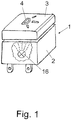
- Fig. 1 can be seen in a partially broken, perspective view of an electrical switch 1, which is used for example in a motor vehicle as an operating element for activating a function by the user.
- the switch 1 has a housing 2, at least one lamp 16, which is only shown schematically, being located in the interior of the housing 2.
- the further internal structure of the housing 2 is not shown in this context for the sake of simplicity.
- an actuator 3 is located on the housing 2, which in the present exemplary embodiment is configured as a component 3 with a picture element 4.
- the picture element 4 can form a symbol, a display or the like for the visualization of functions, states or the like in the motor vehicle.
- the picture element 4 can be illuminated with the illuminant 16 and thus, for example, a function of the motor vehicle can be made visible to the user.
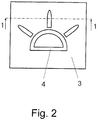
- Fig. 2 component 3 with image element 4 is shown in a top view.
- the picture element 4 shown can represent, for example, the symbol of the function "switching on the interior lighting in the motor vehicle".
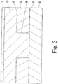
- Fig. 3 the configuration of the component 3 with the picture element 4 according to a first embodiment can be seen in a schematic sectional view.
- the component 3 has a first component 5 consisting of a first side 6 and a second side 7.
- For the first Component 5 is an essentially opaque material, which can be black, for example.
- At least one opening 8 is located between the first side 6 and the second side 7 of the first component 5, the opening 8 forming the picture element 4.
- the second component 9 is located adjacent to the second side 7 of the first component 5.
- the material of the second component 9 is essentially translucent and can for example be white and / or diffuse. In this case, the second component 9 forms an optical differentiation of the picture element 4 from the first component 5 for the viewer. This creates a homogeneous representation of the picture element 4 with a regular line width while maintaining the specified line width.
- the third component 10 Adjacent to the first side 6 of the first component 5 and filling the opening 8 and further adjacent to the second component 9 in the area of the opening 8, the third component 10 is located.
- a transparent material is provided for the third component 10, which may be polymethyl methacrylate (PMMA), polycarbonate (PC) or the like.
- PMMA polymethyl methacrylate
- PC polycarbonate
- the third component 10 can have a thickness of at least 1 mm.
- a fourth component 11 can be applied to the surface of the third component 10.
- the fourth component 11 is transparent to light and serves as a wear-resistant scratch protection layer. As a result, the component 3 is protected against possible damage from external influences.
- Fig. 4 the configuration of the component 3 with the picture element 4 according to a second embodiment is shown in a schematic sectional view.
- the component 3 has a first component 5 consisting of a first side 6 and a second side 7.
- An essentially opaque material is provided for the first component 5, which can be black, for example.
- At least one opening 8 is located between the first side 6 and the second side 7 of the first component 5, the opening 8 forming the picture element 4.
- Adjacent to the second side 7 of the first component 5 and the opening 8 partially filling at a distance from the first side 6 of the first Component 5 is the second component 9.
- the material of the second component 9 is essentially translucent and can for example be white and / or diffuse. In this case, the second component 9 forms an optical differentiation of the picture element 4 from the first component 5 for the viewer. This creates a homogeneous representation of the picture element 4 with a regular line width while maintaining the specified line width.
- the third component 10 is located adjacent to the first side 6 of the first component 5 and fills the remaining opening 8 and further adjacent to the second component 9 in the region of the opening 8.
- a transparent material is provided for the third component 10, which may be polymethyl methacrylate (PMMA), polycarbonate (PC) or the like.
- PMMA polymethyl methacrylate
- PC polycarbonate
- the third component 10 can have a thickness of at least 1 mm.
- the depth effect can be varied in an advantageous manner by changing the distance between the second component 9 and the first side 6 of the first component 5 in the opening 8 accordingly.
- the fourth component 11 can then be applied to the surface of the third component 10.
- the fourth component 11 is transparent to light and serves as a wear-resistant scratch protection layer. As a result, the component 3 is protected against possible damage from external influences.
- Fig. 5 is a schematic sectional view through the first component 5 of the component 3 in the sectional plane 1-1 from Fig. 2 illustrated, which has a first side 6 and a second side 7. Essentially an opaque material is provided for the first component 5. At least one opening 8 is located between the first side 6 and the second side 7 of the first component 5. The opening 8 advantageously forms the picture element 4.
- Fig. 6 2 shows a schematic sectional view of the first component 5, which is in a first tool part 12 and a second tool part 13 located in a first position in the cutting plane 1-1
- Fig. 2 is designed according to the first embodiment.
- an opaque material is provided for the first component 5, which can be black, for example.
- the first tool part 12 is designed such that in the first component 5 there is at least one opening 8 between the first side 6 and the second side 7 of the first component 5, specifically by the first tool part 12 having a tool piece 19 with rounded edges in the Has type of an embossing stamp, the opening 8 forming the image element 4.
- the tool piece 19 corresponding to the opening 8 is raised as a tool core in the first tool part 12.
- Fig. 7 is a schematic sectional view of the second component 9 formed in the first tool part 12 and in the second tool part 13 located in the second position in the cutting plane 1-1 from Fig. 2 recognizable according to the first embodiment.
- the material of the second component 9 is essentially translucent and can for example be white and / or diffuse.
- the second tool part 13 is moved from the first position into a second position, wherein the movement of the second tool part 13 can take place translationally according to arrow 17.
- the second component 9 is then formed in the cavity as a layer adjacent to the second side 7 of the first component 5.
- the opening 8 is stabilized in an advantageous manner by the first tool part 12 and a possible deformation of the opening 8 is avoided.
- a homogeneous representation of the picture element 4 with a regular line width while maintaining the specified line width is thus ensured.
- Fig. 8 is a schematic sectional view of the third component 10 formed in a third tool part 14 and in the second tool part 13 located in the second position in the sectional plane 1-1 from Fig. 2 shown according to the first embodiment.
- the first tool part 12 is substituted by a third tool part 14 to form a cavity at a distance from the first side 6 of the first component 5.
- a material which is transparent to light is essentially provided for the third component 10, this being polymethyl methacrylate (PMMA), polycarbonate (PC) can act.
- PMMA polymethyl methacrylate
- PC polycarbonate
- the third component 10 is formed in the cavity as a layer adjacent to the first side 6 of the first component 5 and filling the opening 8 and adjacent to the second component 9 in the region of the opening 8.
- the first component 5 and the second component 9 and the third component 10 of the component 3 can be produced in an injection molding process, in particular in a multi-component injection molding process, in a simple and cost-effective manner. If desired, the fourth component 11 can then be applied adjacent to the third component 10 in a cover molding process or in a painting process, so that it forms a wear-resistant scratch protection layer.
- Fig. 9 is a schematic sectional view of the first component 5 formed in the first tool part 12 with a tool element 15 in the first position and in the second tool part 13 in the first plane in the sectional plane 1-1 Fig. 2 to see according to the second embodiment.
- an opaque material is provided for the first component 5, which can be black, for example.
- the first tool part 12 has a tool element 15 located in a first position and is designed such that in the first component 5 there is at least one opening 8 between the first side 6 and the second side 7 of the first component 5, the opening 8 here the picture element 4 forms.
- the tool element 15 corresponding to the opening 8 is raised in the first tool part 12, in the manner of an embossing stamp with rounded edges.
- Fig. 10 is a schematic sectional view of the second component formed in the first tool part 12 with the tool element 15 in the second position and in the second tool part 13 in the second position in the sectional plane 1-1 Fig. 2 according to the second embodiment.
- the material of the second component 9 is essentially translucent and can for example be white and / or diffuse.
- the tool element 15 located in the first tool part 12 is moved from the first position into a second position, the movement of the tool element 13 translationally can be done according to arrow 18.
- the second tool part 13 is further moved from the first position into a second position, the movement of the second tool part 13 here being able to take place in a translatory manner according to the arrow 17.
- the second component 9 is formed in the cavity as a layer adjacent to the second side 7 of the first component 5 and partially filling the opening 8 at a distance from the first side 6 of the first component 5.
- the area of the opening 8 adjoining the cavity is advantageously stabilized by the tool element 15 in the first tool part 12 and a possible deformation of the opening 8 is thus avoided.
- a homogeneous representation of the picture element 4 with a regular line width while maintaining the specified line width is thus ensured.
- FIG. 11 a schematic sectional view of the third component 10 formed in the third tool part 14 and in the second tool part 13 located in the second position in the cutting plane 1-1 Fig. 2 shown according to the second embodiment.
- the first tool part 12 is substituted by a third tool part 14 to form a cavity at a distance from the first side 6 of the first component 5.
- a material which is transparent to light is essentially provided for the third component 10, which may be polymethyl methacrylate (PMMA), polycarbonate (PC) or the like.
- PMMA polymethyl methacrylate
- PC polycarbonate
- the first component 5 and the second component 9 and the third component 10 of the component 3 can be produced in an injection molding process, in particular in a multi-component injection molding process, in a simple and cost-effective manner. If desired, the fourth component 11 can then be applied adjacent to the third component 10 in a cover molding process or in a painting process, so that it forms a wear-resistant scratch protection layer.
- the invention is not restricted to the exemplary embodiments described and illustrated. Rather, it also includes all professional training within the framework the invention defined by the claims. Thus, the invention can be used not only on display and / or control elements in the vehicle but also on other devices, for example household appliances, machine tools, computer controls or the like.
Landscapes
- Engineering & Computer Science (AREA)
- Physics & Mathematics (AREA)
- General Physics & Mathematics (AREA)
- Theoretical Computer Science (AREA)
- Automation & Control Theory (AREA)
- Marketing (AREA)
- Accounting & Taxation (AREA)
- Business, Economics & Management (AREA)
- Manufacturing & Machinery (AREA)
- Ink Jet Recording Methods And Recording Media Thereof (AREA)
- Laminated Bodies (AREA)
- Injection Moulding Of Plastics Or The Like (AREA)
- Illuminated Signs And Luminous Advertising (AREA)
Abstract
Description
- Die Erfindung betrifft ein Bauteil mit einem Bildelement nach dem Oberbegriff des Patentanspruchs 1.
- Ein derartiges Bauteil kann als Bedienelement in einem Kraftfahrzeug zur Bedienung von Funktionen verwendet werden. Das im Bauteil befindliche Bildelement dient dann zur Visualisierung der jeweiligen Funktion für den Benutzer. Desweiteren kann das Bildelement auch in sonstiger Weise zur Visualisierung von Funktionen, Zuständen o. dgl. im Kraftfahrzeug dienen. Insbesondere findet die Erfindung Anwendung bei der Darstellung von Symbolen, Anzeigen o. dgl. für Bedienoberflächen.
- Aus der
DE 10 2015 222 304 A1 ist ein derartiges Bauteil für ein Bedienelement bekannt. Dieses Bauteil weist wenigstens ein Bildelement auf. Bei dem Bildelement kann es sich um ein Symbol oder eine Anzeige handeln. Das Bauteil weist eine erste Komponente mit einer ersten und einer zweiten Seite auf. Angrenzend an die erste Komponente ist eine zweite Komponente befindlich. Des Weiteren ist angrenzend an die erste Komponente eine dritte Komponente vorhanden, wobei die dritte Komponente transparent ist. Auf die Oberfläche der dritten Komponente ist eine vierte Komponente aufgebracht. Die vierte Komponente ist für Licht transparent und dient als verschleißfeste Kratzschutzschicht. - Bei dem bekannten Bauteil ist das Bildelement in der ersten Komponente als erhabenes Symbol ausgebildet. Dabei besteht die erste Komponente aus einem weißen lichtdurchlässigen Material. Desweiteren ist die zweite Komponente aus einem schwarzen Material ausgebildet. Die zweite Komponente ist angrenzend an die erste Komponente im Bereich des Bildelements derart umspritzt, dass nur das Bildelement und die zweite Komponente für den Betrachter sichtbar sind. Angrenzend daran ist die dritte Komponente mit einer Dicke von 1-2mm angespritzt und erzeugt den gewünschten Tiefeneffekt des Bildelements. Als Material für die dritte Komponente ist insbesondere Polymethylmethacrylat (PMMA), Polycarbonat (PC) o. dgl. vorgesehen. Die vierte Komponente auf der Oberfläche der dritten Komponente dient dann als Kratzschutz.
- Es hat sich herausgestellt, dass bei der bekannten Anordnung der Komponenten eine homogene Darstellung des Bildelements schwierig ist. Außerdem ergibt sich eine unregelmäßige Strichstärke des Bildelements. Ferner sind die Vorgaben an die Strichstärke des Bildelements schwer einzuhalten.
- Der Erfindung liegt die Aufgabe zugrunde, das Bauteil mit einem Bildelement derart weiterzuentwickeln, dass eine homogene Darstellung des Bildelements und/oder eine regelmäßige Strichstärke des Bildelements und/oder eine Einhaltung der vorgegebenen Strichstärke des Bildelements erzielt sind.
- Diese Aufgabe wird bei einem gattungsgemäßen Bauteil mit einem Bildelement durch die kennzeichnenden Merkmale des Anspruchs 1 gelöst.
- Bei dem erfindungsgemäßen Bauteil mit einem Bildelement gemäß einer ersten Ausführung besteht die erste Komponente im Wesentlichen aus einem lichtundurchlässigen Material. Des Weiteren weist die erste Komponente wenigstens einen Durchbruch zwischen der ersten Seite und der zweiten Seite auf, wobei der Durchbruch das Bildelement bildet. Angrenzend an die zweite Seite der ersten Komponente ist die zweite Komponente befindlich. Das Material der zweiten Komponente ist im Wesentlichen lichtdurchlässig. Angrenzend an die erste Seite der ersten Komponente und den Durchbruch ausfüllend sowie weiter angrenzend an die zweite Komponente im Bereich des Durchbruchs ist die dritte Komponente befindlich.
- Bei dem erfindungsgemäßen Bauteil mit einem Bildelement gemäß einer zweiten Ausführung besteht die erste Komponente im Wesentlichen aus einem lichtundurchlässigen Material. Des Weiteren weist die erste Komponente wenigstens einen Durchbruch zwischen der ersten Seite und der zweiten Seite auf, wobei der Durchbruch das Bildelement bildet. Angrenzend an die zweite Seite der ersten Komponente und den Durchbruch teilweise ausfüllend in einem Abstand zur ersten Seite der ersten Komponente ist die zweite Komponente befindlich. Das Material der zweiten Komponente ist im Wesentlichen lichtdurchlässig. Angrenzend an die erste Seite der ersten Komponente und den restlichen Durchbruch ausfüllend sowie weiter angrenzend an die zweite Komponente im Bereich des Durchbruchs ist die dritte Komponente befindlich.
- Weitere Ausgestaltungen der Erfindung sind Gegenstand der Unteransprüche.
- Zweckmäßigerweise kann das Material der ersten Komponente schwarz sein. Ferner kann das Material der zweiten Komponente weiß und/oder diffus sein. Die zweite Komponente bildet in diesem Fall eine optische Differenzierung des Bildelements zur ersten Komponente für den Betrachter. Somit ist eine homogene Darstellung des Bildelements mit regelmäßiger Strichstärke unter Einhaltung der vorgegebenen Strichstärke geschaffen.
- Desweiteren kann es sich beim Material der dritten Komponente um Polymethylmethacrylat (PMMA), Polycarbonat (PC) o. dgl. handeln. In einfacher Art und Weise kann dann die dritte Komponente ein dreidimensionales, optisches Erscheinungsbild des Bildelements für den Betrachter bilden, insbesondere einen Tiefeneffekt aufweisen. Um den gewünschten Tiefeneffekt zu bewirken, kann die dritte Komponente eine Dicke von wenigstens 1 mm aufweisen.
- In weiterer Ausgestaltung kann die dritte Komponente derart ausgeführt sein, dass diese ein veränderliches, dreidimensionales, optisches Erscheinungsbild des Bildelements für den Betrachter bildet, insbesondere kann diese einen Tiefeneffekt aufweisen. Auf diese Weise kann die Ausgestaltung des Tiefeneffekts in vorteilhafter Weise variiert werden.
- Die Erfindung stellt weiter ein Verfahren zur Herstellung des Bauteils mit einem Bildelement gemäß der ersten Ausführung bereit, wobei es sich beim Bildelement um ein Symbol, eine Anzeige o. dgl. handelt.
- Zunächst wird in einem ersten Werkzeugteil und einem in einer ersten Position befindlichen zweiten Werkzeugteil die erste Komponente mit einer ersten sowie einer zweiten Seite gebildet, wobei das Material der ersten Komponente im Wesentlichen lichtundurchlässig ist. Das erste Werkzeugteil ist derart ausgebildet, dass in der ersten Komponente wenigstens ein Durchbruch zwischen der ersten Seite und der zweiten Seite befindlich ist, wobei der Durchbruch das Bildelement bildet. Danach wird das zweite Werkzeugteil aus der ersten Position in die zweite Position unter Bildung einer Kavität in einem Abstand zur zweiten Seite der ersten Komponente bewegt. Angrenzend an die zweite Seite der ersten Komponente wird die zweite Komponente in der Kavität als eine Schicht gebildet und dabei der Durchbruch vom ersten Werkzeugteil stabilisiert. Für die zweite Komponente ist im Wesentlichen ein teilweise lichtdurchlässiges Material vorgesehen. Als nächstes wird das erste Werkzeugteil durch ein drittes Werkzeugteil unter Bildung einer Kavität in einem Abstand zur ersten Seite der ersten Komponente substituiert. Angrenzend an die erste Seite der ersten Komponente und den Durchbruch ausfüllend sowie angrenzend an die zweite Komponente im Bereich des Durchbruchs wird die dritte Komponente in der Kavität als eine weitere Schicht gebildet. Für die dritte Komponente ist im Wesentlichen ein für Licht transparentes Material vorgesehen. Falls gewünscht kann schließlich dann die vierte Komponente angrenzend an die dritte Komponente aufgebracht werden, derart dass diese eine verschleißfeste Kratzschutzschicht bildet.
- Des Weiteren stellt die Erfindung ein Verfahren zur Herstellung des Bauteils mit einem Bildelement gemäß der zweiten Ausführung bereit, wobei es sich beim Bildelement um ein Symbol, eine Anzeige o. dgl. handelt.
- Zunächst wird in einem ersten Werkzeugteil und einem in einer ersten Position befindlichen zweiten Werkzeugteil die erste Komponente mit einer ersten sowie einer zweiten Seite gebildet, wobei das Material der ersten Komponente im Wesentlichen lichtundurchlässig ist. Das erste Werkzeugteil weist ein in einer ersten Position befindliches Werkzeugelement auf und ist derart ausgebildet, dass in der ersten Komponente wenigstens ein Durchbruch zwischen der ersten Seite und der zweiten Seite befindlich ist, wobei der Durchbruch das Bildelement bildet. Danach wird das im ersten Werkzeugteil befindliche Werkzeugelement aus der ersten Position in eine zweite Position unter Bildung einer Kavität im Durchbruch angrenzend zur zweiten Seite der ersten Komponente und in einem Abstand zur ersten Seite der ersten Komponente bewegt. Des Weiteren wird das zweite Werkzeugteil aus der ersten Position in die zweite Position unter Bildung einer Kavität in einem Abstand zur zweiten Seite der ersten Komponente bewegt. Angrenzend an die zweite Seite der ersten Komponente und den Durchbruch teilweise ausfüllend wird die zweite Komponente in der Kavität als eine weitere Schicht gebildet und dabei der an die Kavität angrenzende Bereich des Durchbruchs vom dritten Werkzeugteil stabilisiert. Für die zweite Komponente ist im Wesentlichen ein teilweise lichtdurchlässiges Material vorgesehen. Als nächstes wird das erste Werkzeugteil durch ein drittes Werkzeugteil unter Bildung einer Kavität in einem Abstand zur ersten Seite der ersten Komponente substituiert. Angrenzend an die erste Seite der ersten Komponente und den restlichen Durchbruch ausfüllend sowie angrenzend an die zweite Komponente im Bereich des Durchbruchs wird die dritte Komponente in der Kavität als eine weitere Schicht gebildet. Für die dritte Komponente ist im Wesentlichen ein für Licht transparentes Material vorgesehen. Schließlich kann, falls gewünscht, dann die vierte Komponente angrenzend an die dritte Komponente aufgebracht werden, derart dass diese eine verschleißfeste Kratzschutzschicht bildet.
- In einer weiteren Ausgestaltung kann es sich anbieten, die erste Komponente und die zweite Komponente sowie die dritte Komponente des Bauteils in einem Spritzgießverfahren, insbesondere in einem Mehrkomponenten-Spritzgießverfahren, zu bilden. Das Bauteil kann somit in einfacher sowie kostengünstiger Art und Weise hergestellt werden.
- In einer vorteilhaften Ausgestaltung können das zum Durchbruch korrespondierende Werkzeugstück im ersten Werkzeugteil und/oder das zum Durchbruch korrespondierende Werkzeugelement im ersten Werkzeugteil erhaben ausgebildet sein. Beispielsweise können das Werkzeugstück und/oder das Werkzeugelement in der Art eines Prägestempels ausgestaltet sein. Des Weiteren können das Werkzeugstück und/oder das Werkzeugelement abgerundete Kanten aufweisen, um eventuellen unerwünschten Schatteneffekten am Bildelement vorzubeugen. Für die Bildung der Kavität kann ferner das zweite Werkzeugteil aus der ersten Position in die zweite Position translatorisch bewegbar sein. Eine weitere Kavität kann gebildet werden, indem das im ersten Werkzeugteil befindliche Werkzeugelement aus der ersten Position in die zweite Position translatorisch bewegbar ist.
- Zweckgemäß kann die vierte Komponente in einem Coverformingverfahren oder in einem Lackierverfahren gebildet werden, wobei diese dann als verschleißfeste Kratzschutzschicht dient. Dadurch ist das Bauteil vor möglichen Beschädigungen durch äußere Einflüsse geschützt.
- Für eine besonders bevorzugte Ausgestaltung der Erfindung ist nachfolgendes festzustellen.
- Im Automobilbereich sind häufig Tiefeneffekte bei Anzeigeelementen erwünscht. Beim Tiefeneffekt wird ein dreidimensionales, optisches Erscheinungsbild des Anzeigeelementes für den Betrachter erzeugt. Für diesen Effekt kann eine bedruckte Folie mit einem transparenten Kunststoff, wie z.B. PMMA, überspritzt werden. Durch den transparenten Kunststoff wird der Tiefeneffekt erreicht. Die Folientechnologie ist sehr kostenintensiv. Zwecks Einsparung von Kosten stellt die Erfindung eine eingespritzte Symbolik bereit. Im Vergleich zur Folientechnologie ist dadurch in vorteilhafter Weise ein Kostenvorteil erzielt.
- Bisher wird die Symbolik in der folgenden Weise gespritzt. Die weiße lichtdurchlässige Komponente mit erhabener Symbolik wird gespritzt. Dann wird die schwarze Komponente gespritzt, um die erhabene Symbolik zu umspritzen. Danach sind nur die Symbolik und das schwarze Material sichtbar. Für den Tiefeneffekt wird anschließend der transparente Werkstoff gespritzt, wobei es sich beim transparenten Werkstoff häufig um ein Polymethylmethacrylat (PMMA) handelt. Zuletzt kann im Werkzeug der Kratzschutz im Coverformingverfahren durch Einbringen von Acrylaten hergestellt werden.
- Prozesstechnisch kann diese Lösung schwierig in der Umsetzung sein. Die erhabene Symbolik wird durch die zweite Komponente beim Einspritzen verformt. Dadurch ergibt sich kein homogenes Bild der Symbolik bzw. die Strichstärke ist unregelmäßig. Auch sind die Vorgaben an die Symbolstärke schwierig einzuhalten.
- Durch eine andere Anordnung der Materialien, die erfindungsgemäß vorgeschlagen wird, lassen sich solche Probleme umgehen. Und zwar wird folgende Reihenfolge vorgeschlagen, die nachfolgend beschrieben wird.
- Die schwarze Komponente wird als Erstes gespritzt. Im Werkzeug ist die Symbolik erhaben dargestellt, sodass im schwarzen Material dadurch die Symbolik abgebildet wird. Die Symbolik taucht sozusagen durch die schwarze Komponente durch. Die Symbolik ist gegebenenfalls an den Kanten etwas abgerundet, um keine Schatteneffekte zu erzeugen.
- Die weiße Komponente, die lichtdurchlässig und/oder leicht diffus sein kann, wird an die schwarze Komponente angespritzt. Das weiße Material im Kontrast zum schwarzen Material ist als Symbolik zu erkennen. Der Werkzeugkern der Symbolik ist noch in dem schwarzen Material eingetaucht und stützt somit vorteilhafterweise die Kontur vor einer möglichen Verformung. Das weiße Material hat lichtstreuende Wirkung und wirkt in der Erscheinung homogen. Das schwarze Material lässt nunmehr nur an der Stelle Licht durch, an dem der Durchbruch ist.
- Danach wird der Werkzeugkern für die Symbolik entfernt und die transparente Schicht, die aus PMMA bestehen kann, wird aufgebracht. In der Regel wird eine Dicke von ca. 1 - 2 mm aufgebracht. Das transparente Material ist nun deckend über dem schwarzen Material und füllt zusätzlich nun die Symbolbereiche. Dadurch wird der Tiefeneffekt erreicht. Falls gewünscht kann nun noch ein Kratzschutz aufgebracht werden. Dies kann im Coverformingverfahren oder im Lackierverfahren geschehen.
- Die mit der Erfindung erzielten Vorteile bestehen insbesondere darin, dass prozesstechnische Probleme mit dem eingespritzten Bildelement behoben werden. Auf diese Weise können eine homogene Darstellung des Bildelements und/oder eine regelmäßige Strichstärke des Bildelements und/oder eine Einhaltung der vorgegebenen Strichstärke des Bildelements erzielt werden. Desweiteren ergibt sich ein Kostenvorteil gegenüber der Folientechnik.
- Ausführungsbeispiele der Erfindung sind in den Zeichnungen dargestellt und werden im Folgenden näher beschrieben. Es zeigen
- Fig. 1
- eine teilweise aufgebrochene, perspektivische Ansicht eines elektrischen Schalters umfassend ein Gehäuse mit einem Leuchtmittel sowie ein Betätigungsorgan,
- Fig. 2
- eine Draufsicht auf das Betätigungsorgan als ein Bauteil,
- Fig. 3
- eine schematische Schnittansicht des Bauteils in der Schnittebene 1-1 aus
Fig. 2 gemäß einer ersten Ausführung, - Fig. 4
- eine schematische Schnittansicht des Bauteils in der Schnittebene 1-1 aus
Fig. 2 gemäß einer zweiten Ausführung, - Fig. 5
- eine schematische Schnittansicht durch eine erste Komponente des Bauteils in der Schnittebene 1-1 aus
Fig. 2 , - Fig. 6
- eine schematische Schnittansicht der ersten Komponente ausgebildet in einem ersten Werkzeugteil sowie einem in einer ersten Position befindlichen zweiten Werkzeugteil in der Schnittebene 1-1 aus
Fig. 2 gemäß der ersten Ausführung, - Fig. 7
- eine schematische Schnittansicht einer zweiten Komponente ausgebildet im ersten Werkzeugteil sowie im in der zweiten Position befindlichen zweiten Werkzeugteil in der Schnittebene 1-1 aus
Fig. 2 gemäß der ersten Ausführung, - Fig. 8
- eine schematische Schnittansicht einer dritten Komponente ausgebildet in einem dritten Werkzeugteil sowie im in der zweiten Position befindlichen zweiten Werkzeugteil in der Schnittebene 1-1 aus
Fig. 2 gemäß der ersten Ausführung, - Fig. 9
- eine schematische Schnittansicht der ersten Komponente ausgebildet im ersten Werkzeugteil mit einem in der ersten Position befindlichen Werkzeugelement sowie im in der ersten Position befindlichen zweiten Werkzeugteil in der Schnittebene 1-1 aus
Fig. 2 gemäß der zweiten Ausführung, - Fig. 10
- eine schematische Schnittansicht der zweiten Komponente ausgebildet im ersten Werkzeugteil mit in der zweiten Position befindlichen Werkzeugelement sowie im in der zweiten Position befindlichen zweiten Werkzeugteil in der Schnittebene 1-1 aus
Fig. 2 gemäß der zweiten Ausführung und - Fig. 11
- eine schematische Schnittansicht der dritten Komponente ausgebildet im dritten Werkzeugteil sowie im in der zweiten Position befindlichen zweiten Werkzeugteil in der Schnittebene 1-1 aus
Fig. 2 gemäß der zweiten Ausführung. - In
Fig. 1 ist in teilweise aufgebrochener, perspektivischer Ansicht ein elektrischer Schalter 1 zu sehen, der beispielsweise in einem Kraftfahrzeug als Bedienelement zur Aktivierung einer Funktion durch den Benutzer Verwendung findet. Der Schalter 1 weist ein Gehäuse 2 auf, wobei im Inneren des Gehäuses 2 wenigstens ein lediglich schematisch dargestelltes Leuchtmittel 16 befindlich ist. Der weitere Innenaufbau des Gehäuses 2 ist in diesem Zusammenhang einfachheitshalber nicht näher dargestellt. Desweiteren ist am Gehäuse 2 ein Betätigungsorgan 3 befindlich, das im vorliegenden Ausführungsbeispiel als ein Bauteil 3 mit einem Bildelement 4 ausgestaltet ist. Das Bildelement 4 kann dabei ein Symbol, eine Anzeige o. dgl. zur Visualisierung von Funktionen, Zuständen o. dgl. im Kraftfahrzeug bilden. Vorteilhafterweise kann das Bildelement 4 mit dem Leuchtmittel 16 ausgeleuchtet und so beispielsweise eine Funktion des Kraftfahrzeuges für den Benutzer sichtbar gemacht werden. - In
Fig. 2 ist in einer Draufsicht das Bauteil 3 mit dem Bildelement 4 näher dargestellt. Das gezeigte Bildelement 4 kann beispielsweise das Symbol der Funktion "Einschalten der Innenraumbeleuchtung im Kraftfahrzeug" darstellen. - In
Fig. 3 ist in einer schematischen Schnittansicht die Ausgestaltung des Bauteils 3 mit dem Bildelement 4 gemäß einer ersten Ausführung ersichtlich. Das Bauteil 3 weist eine aus einer ersten Seite 6 und einer zweiten Seite 7 bestehende erste Komponente 5 auf. Für die erste Komponente 5 ist ein im Wesentlichen lichtundurchlässiges Material vorgesehen, das beispielsweise schwarz sein kann. Zwischen der ersten Seite 6 und der zweiten Seite 7 der ersten Komponente 5 ist wenigstens ein Durchbruch 8 befindlich, wobei der Durchbruch 8 das Bildelement 4 bildet. Angrenzend an die zweite Seite 7 der ersten Komponente 5 ist die zweite Komponente 9 befindlich. Das Material der zweiten Komponente 9 ist im Wesentlichen lichtdurchlässig und kann beispielsweise weiß und/oder diffus sein. Die zweite Komponente 9 bildet in diesem Fall eine optische Differenzierung des Bildelements 4 zur ersten Komponente 5 für den Betrachter. Somit ist eine homogene Darstellung des Bildelements 4 mit regelmäßiger Strichstärke unter Einhaltung der vorgegebenen Strichstärke geschaffen. - Angrenzend an die erste Seite 6 der ersten Komponente 5 und den Durchbruch 8 ausfüllend sowie weiter angrenzend an die zweite Komponente 9 im Bereich des Durchbruchs 8 ist die dritte Komponente 10 befindlich. Für die dritte Komponente 10 ist ein transparentes Material vorgesehen, wobei es sich hierbei um Polymethylmethacrylat (PMMA), Polycarbonat (PC) o. dgl. handeln kann. Auf diese Weise kann dann ein dreidimensionales, optisches Erscheinungsbild des Bildelements 4 für den Betrachter gebildet werden, wobei es sich hierbei insbesondere um einen Tiefeneffekt handelt. Um den gewünschten Tiefeneffekt zu bewirken, kann die dritte Komponente 10 eine Dicke von wenigstens 1 mm aufweisen. Auf die Oberfläche der dritten Komponente 10 kann eine vierte Komponente 11 aufgebracht sein. Die vierte Komponente 11 ist für Licht transparent und dient als verschleißfeste Kratzschutzschicht. Dadurch ist das Bauteil 3 vor möglichen Beschädigungen durch äußere Einflüsse geschützt.
- In
Fig. 4 ist in einer schematischen Schnittansicht die Ausgestaltung des Bauteils 3 mit dem Bildelement 4 gemäß einer zweiten Ausführung aufgezeigt. Das Bauteil 3 weist eine aus einer ersten Seite 6 und einer zweiten Seite 7 bestehende erste Komponente 5 auf. Für die erste Komponente 5 ist ein im Wesentlichen lichtundurchlässiges Material vorgesehen, das beispielsweise schwarz sein kann. Zwischen der ersten Seite 6 und der zweiten Seite 7 der ersten Komponente 5 ist wenigstens ein Durchbruch 8 befindlich, wobei der Durchbruch 8 das Bildelement 4 bildet. Angrenzend an die zweite Seite 7 der ersten Komponente 5 und den Durchbruch 8 teilweise ausfüllend in einem Abstand zur ersten Seite 6 der ersten Komponente 5 ist die zweite Komponente 9 befindlich. Das Material der zweiten Komponente 9 ist im Wesentlichen lichtdurchlässig und kann beispielsweise weiß und/oder diffus sein. Die zweite Komponente 9 bildet in diesem Fall eine optische Differenzierung des Bildelements 4 zur ersten Komponente 5 für den Betrachter. Somit ist eine homogene Darstellung des Bildelements 4 mit regelmäßiger Strichstärke unter Einhaltung der vorgegebenen Strichstärke geschaffen. - Angrenzend an die erste Seite 6 der ersten Komponente 5 und den restlichen Durchbruch 8 ausfüllend sowie weiter angrenzend an die zweite Komponente 9 im Bereich des Durchbruchs 8 ist die dritte Komponente 10 befindlich. Für die dritte Komponente 10 ist ein transparentes Material vorgesehen, wobei es sich hierbei um Polymethylmethacrylat (PMMA), Polycarbonat (PC) o. dgl. handeln kann. Auf diese Weise kann dann ein veränderliches, dreidimensionales, optisches Erscheinungsbild des Bildelements 4 für den Betrachter gebildet werden, wobei es sich hierbei insbesondere um einen Tiefeneffekt handelt. Um den gewünschten Tiefeneffekt zu bewirken, kann die dritte Komponente 10 eine Dicke von wenigstens 1 mm aufweisen. Bei dieser Ausgestaltung kann der Tiefeneffekt in vorteilhafter Weise variiert werden, indem der Abstand der zweiten Komponente 9 zur ersten Seite 6 der ersten Komponente 5 im Durchbruch 8 entsprechend verändert wird. Auf die Oberfläche der dritten Komponente 10 kann dann die vierte Komponente 11 aufgebracht sein. Die vierte Komponente 11 ist für Licht transparent und dient als verschleißfeste Kratzschutzschicht. Dadurch ist das Bauteil 3 vor möglichen Beschädigungen durch äußere Einflüsse geschützt.
- In
Fig. 5 ist eine schematische Schnittansicht durch die erste Komponente 5 des Bauteils 3 in der Schnittebene 1-1 ausFig. 2 veranschaulicht, wobei diese eine erste Seite 6 und eine zweite Seite 7 aufweist. Für die erste Komponente 5 ist im Wesentlichen ein lichtundurchlässiges Material vorgesehen. Zwischen der ersten Seite 6 und der zweiten Seite 7 der ersten Komponente 5 ist wenigstens ein Durchbruch 8 befindlich. In vorteilhafter Weise bildet der Durchbruch 8 das Bildelement 4. - Nachfolgend ist die Herstellung des Bauteils 3 näher beschrieben. So zeigt
Fig. 6 eine schematische Schnittansicht der ersten Komponente 5, die in einem ersten Werkzeugteil 12 sowie einem in einer ersten Position befindlichem zweiten Werkzeugteil 13 in der Schnittebene 1-1 ausFig. 2 gemäß der ersten Ausführung ausgebildet ist. Für die erste Komponente 5 ist im Wesentlichen ein lichtundurchlässiges Material vorgesehen, das beispielsweise schwarz sein kann. Das erste Werkzeugteil 12 ist derart ausgebildet, dass in der ersten Komponente 5 wenigstens ein Durchbruch 8 zwischen der ersten Seite 6 und der zweiten Seite 7 der ersten Komponente 5 befindlich ist, und zwar indem das erste Werkzeugteil 12 ein Werkzeugstück 19 mit abgerundeten Kanten in der Art eines Prägestempels aufweist, wobei der Durchbruch 8 hierbei das Bildelement 4 bildet. In zweckmäßiger Ausgestaltung ist dabei das zum Durchbruch 8 korrespondierende Werkzeugstück 19 als ein Werkzeugkern im ersten Werkzeugteil 12 erhaben ausgebildet. - In
Fig. 7 ist eine schematische Schnittansicht der zweiten Komponente 9 ausgebildet im ersten Werkzeugteil 12 sowie im in der zweiten Position befindlichen zweiten Werkzeugteil 13 in der Schnittebene 1-1 ausFig. 2 gemäß der ersten Ausführung zu erkennen. Das Material der zweiten Komponente 9 ist im Wesentlichen lichtdurchlässig und kann beispielsweise weiß und/oder diffus sein. Zur Bildung einer Kavität in einem Abstand zur zweiten Seite 7 der ersten Komponente 5 wird das zweite Werkzeugteil 13 aus der ersten Position in eine zweite Position bewegt, wobei die Bewegung des zweiten Werkzeugteils 13 hierbei translatorisch gemäß dem Pfeil 17 erfolgen kann. Anschließend wird die zweite Komponente 9 in der Kavität als eine Schicht angrenzend an die zweite Seite 7 der ersten Komponente 5 gebildet. Dabei wird der Durchbruch 8 vom ersten Werkzeugteil 12 in vorteilhafter Weise stabilisiert und so eine mögliche Verformung des Durchbruchs 8 vermieden. Eine homogene Darstellung des Bildelements 4 mit regelmäßiger Strichstärke unter Einhaltung der vorgegebenen Strichstärke ist somit gewährleistet. - In
Fig. 8 ist eine schematische Schnittansicht der dritten Komponente 10 ausgebildet in einem dritten Werkzeugteil 14 sowie im in der zweiten Position befindlichen zweiten Werkzeugteil 13 in der Schnittebene 1-1 ausFig. 2 gemäß der ersten Ausführung dargestellt. Hierfür wird das erste Werkzeugteil 12 durch ein drittes Werkzeugteil 14 unter Bildung einer Kavität in einem Abstand zur ersten Seite 6 der ersten Komponente 5 substituiert. Für die dritte Komponente 10 ist im Wesentlichen ein für Licht transparentes Material vorgesehen, wobei es sich hierbei um Polymethylmethacrylat (PMMA), Polycarbonat (PC) o. dgl. handeln kann. Die dritte Komponente 10 wird in der Kavität als eine Schicht angrenzend an die erste Seite 6 der ersten Komponente 5 und den Durchbruch 8 ausfüllend sowie angrenzend an die zweite Komponente 9 im Bereich des Durchbruchs 8 gebildet. In einfacher sowie kostengünstiger Art und Weise können die erste Komponente 5 und die zweite Komponente 9 sowie die dritte Komponente 10 des Bauteils 3 in einem Spritzgießverfahren, insbesondere in einem Mehrkomponenten-Spritzgießverfahren, hergestellt werden. Falls gewünscht kann dann die vierte Komponente 11 angrenzend an die dritte Komponente 10 in einem Coverformingverfahren oder in einem Lackierverfahren aufgebracht werden, derart dass diese eine verschleißfeste Kratzschutzschicht bildet. - In
Fig. 9 ist eine schematische Schnittansicht der ersten Komponente 5 ausgebildet im ersten Werkzeugteil 12 mit einem in der ersten Position befindlichen Werkzeugelement 15 sowie im in der ersten Position befindlichen zweiten Werkzeugteil 13 in der Schnittebene 1-1 ausFig. 2 gemäß der zweiten Ausführung zu sehen. Für die erste Komponente 5 ist im Wesentlichen ein lichtundurchlässiges Material vorgesehen, das beispielsweise schwarz sein kann. Das erste Werkzeugteil 12 weist ein in einer ersten Position befindliches Werkzeugelement 15 auf und ist derart ausgebildet, dass in der ersten Komponente 5 wenigstens ein Durchbruch 8 zwischen der ersten Seite 6 und der zweiten Seite 7 der ersten Komponente 5 befindlich ist, wobei der Durchbruch 8 hierbei das Bildelement 4 bildet. In zweckmäßiger Ausgestaltung ist dabei das zum Durchbruch 8 korrespondierende Werkzeugelement 15 im ersten Werkzeugteil 12 erhaben ausgebildet, und zwar in der Art eines Prägestempels mit abgerundeten Kanten. - In
Fig. 10 ist eine schematische Schnittansicht der zweiten Komponente ausgebildet im ersten Werkzeugteil 12 mit in der zweiten Position befindlichen Werkzeugelement 15 sowie im in der zweiten Position befindlichen zweiten Werkzeugteil 13 in der Schnittebene 1-1 ausFig. 2 gemäß der zweiten Ausführung ersichtlich. Das Material der zweiten Komponente 9 ist im Wesentlichen lichtdurchlässig und kann beispielsweise weiß und/oder diffus sein. Zur Bildung einer Kavität im Durchbruch 8 angrenzend zur zweiten Seite 7 der ersten Komponente 5 und in einem Abstand zur ersten Seite 6 der ersten Komponente 5 wird das im ersten Werkzeugteil 12 befindliche Werkzeugelement 15 aus der ersten Position in eine zweite Position bewegt, wobei die Bewegung des Werkzeugelements 13 dabei translatorisch gemäß dem Pfeil 18 erfolgen kann. Zur Bildung einer weiteren Kavität in einem Abstand zur zweiten Seite 7 der ersten Komponente 5 wird des Weiteren das zweite Werkzeugteil 13 aus der ersten Position in eine zweite Position bewegt, wobei die Bewegung des zweiten Werkzeugteils 13 hierbei translatorisch gemäß dem Pfeil 17 erfolgen kann. Anschließend wird die zweite Komponente 9 in der Kavität als eine Schicht angrenzend an die zweite Seite 7 der ersten Komponente 5 und den Durchbruch 8 teilweise ausfüllend in einem Abstand zur ersten Seite 6 der ersten Komponente 5 gebildet. Dabei wird der an die Kavität angrenzende Bereich des Durchbruchs 8 vom Werkzeugelement 15 im ersten Werkzeugteil 12 in vorteilhafter Weise stabilisiert und so eine mögliche Verformung des Durchbruchs 8 vermieden. Eine homogene Darstellung des Bildelements 4 mit regelmäßiger Strichstärke unter Einhaltung der vorgegebenen Strichstärke ist somit gewährleistet. - Schließlich ist in
Fig. 11 eine schematische Schnittansicht der dritten Komponente 10 ausgebildet im dritten Werkzeugteil 14 sowie im in der zweiten Position befindlichen zweiten Werkzeugteil 13 in der Schnittebene 1-1 ausFig. 2 gemäß der zweiten Ausführung gezeigt. Hierfür wird das erste Werkzeugteil 12 durch ein drittes Werkzeugteil 14 unter Bildung einer Kavität in einem Abstand zur ersten Seite 6 der ersten Komponente 5 substituiert. Für die dritte Komponente 10 ist im Wesentlichen ein für Licht transparentes Material vorgesehen, wobei es sich hierbei um Polymethylmethacrylat (PMMA), Polycarbonat (PC) o. dgl. handeln kann. Die dritte Komponente 10 wird in der Kavität als eine Schicht angrenzend an die erste Seite 6 der ersten Komponente 5 und den restlichen Durchbruch 8 ausfüllend sowie angrenzend an die zweite Komponente 9 im Bereich des Durchbruchs 8 gebildet. In einfacher sowie kostengünstiger Art und Weise können die erste Komponente 5 und die zweite Komponente 9 sowie die dritte Komponente 10 des Bauteils 3 in einem Spritzgießverfahren, insbesondere in einem Mehrkomponenten-Spritzgießverfahren, hergestellt werden. Falls gewünscht kann dann die vierte Komponente 11 angrenzend an die dritte Komponente 10 in einem Coverformingverfahren oder in einem Lackierverfahren aufgebracht werden, derart dass diese eine verschleißfeste Kratzschutzschicht bildet. - Die Erfindung ist nicht auf die beschriebenen und dargestellten Ausführungsbeispiele beschränkt. Sie umfasst vielmehr auch alle fachmännischen Weiterbildungen im Rahmen der durch die Patentansprüche definierten Erfindung. So kann die Erfindung nicht nur an Anzeige- und/oder Bedienelementen im Fahrzeug sondern auch an sonstigen Geräten, beispielsweise Haushaltsgeräten, Werkzeugmaschinen, Computersteuerungen o. dgl. Verwendung finden.
-
- 1:
- Schalter
- 2:
- Gehäuse
- 3:
- Betätigungsorgan / Bauteil
- 4:
- Bildelement (am Bauteil)
- 5:
- erste Komponente
- 6:
- erste Seite der ersten Komponente
- 7:
- zweite Seite der ersten Komponente
- 8:
- Durchbruch in der ersten Komponente
- 9:
- zweite Komponente
- 10:
- dritte Komponente
- 11:
- vierte Komponente
- 12:
- erstes Werkzeugteil
- 13:
- zweites Werkzeugteil
- 14:
- drittes Werkzeugteil
- 15:
- Werkzeugelement im ersten Werkzeugteil
- 16:
- Leuchtmittel
- 17:
- Pfeil für die translatorische Bewegung des zweiten Werkzeugteils
- 18:
- Pfeil für die translatorische Bewegung des Werkzeugelements im ersten Werkzeugteil
- 19:
- Werkzeugstück
Claims (10)
- Bauteil, insbesondere Bauteil für ein Bedienelement, aufweisend wenigstens ein Bildelement (4), insbesondere ein Symbol, eine Anzeige oder dergleichen, bestehend aus einer eine erste Seite (6) und eine zweite Seite (7) aufweisenden ersten Komponente (5) mit dem Bildelement (4) und aus einer an die erste Komponente (5) angrenzenden zweiten Komponente (9) sowie aus einer weiteren an die erste Komponente (5) angrenzenden dritten Komponente (10), wobei die dritte Komponente (10) transparent ist, und wobei insbesondere auf die Oberfläche der dritten Komponente (10) eine vierte Komponente (11) als für Licht transparente, verschleißfeste Kratzschutzschicht aufgebracht ist, dadurch gekennzeichnet, dass das Material der ersten Komponente (5) im Wesentlichen lichtundurchlässig ist, dass in der ersten Komponente (5) wenigstens ein Durchbruch (8) zwischen der ersten Seite (6) und der zweiten Seite (7) befindlich ist, dass der Durchbruch (8) das Bildelement (4) bildet, dass die zweite Komponente (9) angrenzend an die zweite Seite (7) der ersten Komponente (5) befindlich ist, dass das Material der zweiten Komponente (9) im Wesentlichen lichtdurchlässig ist, und dass die dritte Komponente (10) angrenzend an die erste Seite (6) der ersten Komponente (5) und den Durchbruch (8) ausfüllend sowie angrenzend an die zweite Komponente (9) im Bereich des Durchbruchs (8) befindlich ist.
- Bauteil, insbesondere Bauteil für ein Bedienelement, aufweisend wenigstens ein Bildelement (4), insbesondere ein Symbol, eine Anzeige oder dergleichen, bestehend aus einer eine erste Seite (6) und eine zweite Seite (7) aufweisenden ersten Komponente (5) mit dem Bildelement (4) und aus einer an die erste Komponente (5) angrenzenden zweiten Komponente (9) sowie aus einer weiteren an die erste Komponente (5) angrenzenden dritten Komponente (10), wobei die dritte Komponente (10) transparent ist, und wobei insbesondere auf die Oberfläche der dritten Komponente (10) eine vierte Komponente (11) als für Licht transparente, verschleißfeste Kratzschutzschicht aufgebracht ist, dadurch gekennzeichnet, dass das Material der ersten Komponente (5) im Wesentlichen lichtundurchlässig ist, dass in der ersten Komponente (5) wenigstens ein Durchbruch (8) zwischen der ersten Seite (6) und der zweiten Seite (7) befindlich ist, dass der Durchbruch (8) das Bildelement (4) bildet, dass die zweite Komponente (9) angrenzend an die zweite Seite (7) der ersten Komponente (5) und den Durchbruch (8) teilweise ausfüllend in einem Abstand zur ersten Seite (6) der ersten Komponente (5) befindlich ist, dass das Material der zweiten Komponente (9) im Wesentlichen lichtdurchlässig ist, und dass die dritte Komponente (10) angrenzend an die erste Seite (6) der ersten Komponente (5) und den restlichen Durchbruch (8) ausfüllend sowie angrenzend an die zweite Komponente (9) im Bereich des Durchbruchs (8) befindlich ist.
- Bauteil nach Anspruch 1 oder 2, dadurch gekennzeichnet, dass das Material der ersten Komponente (5) schwarz ist, dass vorzugsweise das Material der zweiten Komponente (9) weiß und/oder diffus ist, derart dass die zweite Komponente (9) eine optische Differenzierung des Bildelements (4) zur ersten Komponente (5) bildet, und dass es sich weiter vorzugsweise bei dem Material der dritten Komponente (10) um Polymethylmethacrylat (PMMA), Polycarbonat (PC) oder dergleichen handelt.
- Bauteil nach Anspruch 1, 2 oder 3, dadurch gekennzeichnet, dass die dritte Komponente (10) ein dreidimensionales, optisches Erscheinungsbild, insbesondere einen Tiefeneffekt, bildet, und dass vorzugsweise die dritte Komponente (10) eine Dicke von wenigstens 1 mm aufweist.
- Bauteil nach einem der Ansprüche 2 bis 4, dadurch gekennzeichnet, dass die dritte Komponente (10) ein veränderliches, dreidimensionales, optisches Erscheinungsbild, insbesondere einen Tiefeneffekt, bildet.
- Verfahren zur Herstellung eines aus mehreren Komponenten bestehenden Bauteils (3), insbesondere nach einem der vorhergehenden Ansprüche, dadurch gekennzeichnet, dass eine erste Komponente (5) mit einem Bildelement (4) vorgesehen ist, wobei es sich bei dem Bildelement (4) insbesondere um ein Symbol, eine Anzeige oder dergleichen handelt, dass die eine erste Seite (6) sowie eine zweite Seite (7) aufweisende erste Komponente (5) in einem ersten Werkzeugteil (12) und einem in einer ersten Position befindlichen zweiten Werkzeugteil (13) gebildet wird, dass das Material für die erste Komponente (5) im Wesentlichen lichtundurchlässig ist, dass das erste Werkzeugteil (12) derart ausgebildet ist, dass in der ersten Komponente (5) wenigstens ein Durchbruch (8) zwischen der ersten Seite (6) und der zweiten Seite (7) der ersten Komponente (5) befindlich ist, dass der Durchbruch (8) das Bildelement (4) bildet, dass das zweite Werkzeugteil (13) aus der ersten Position in eine zweite Position unter Bildung einer Kavität in einem Abstand zur zweiten Seite (7) der ersten Komponente (5) bewegbar ist, dass anschließend eine zweite Komponente (9) in der Kavität als eine Schicht angrenzend an die zweite Seite (7) der ersten Komponente (5) gebildet wird und dabei der Durchbruch (8) vom ersten Werkzeugteil (12) stabilisiert wird, dass das Material für die zweite Komponente (9) im Wesentlichen teilweise lichtdurchlässig ist, dass dann das erste Werkzeugteil (12) durch ein drittes Werkzeugteil (14) unter Bildung einer Kavität in einem Abstand zur ersten Seite (6) der ersten Komponente (5) substituiert wird, dass danach eine dritte Komponente (10) in der Kavität als eine Schicht angrenzend an die erste Seite (6) der ersten Komponente (5) und den Durchbruch (8) ausfüllend sowie angrenzend an die zweite Komponente (9) im Bereich des Durchbruchs (8) gebildet wird, dass das Material für die dritte Komponente (10) im Wesentlichen für Licht transparent ist, und dass gegebenenfalls eine vierte Komponente (11) gebildet wird, derart dass die vierte Komponente (11) eine verschleißfeste Schicht, insbesondere eine Kratzschutzschicht, angrenzend an die dritte Komponente (10) bildet.
- Verfahren zur Herstellung eines aus mehreren Komponenten bestehenden Bauteils (3), insbesondere nach einem der vorhergehenden Ansprüche, dadurch gekennzeichnet, dass eine erste Komponente (5) mit einem Bildelement (4) vorgesehen ist, wobei es sich bei dem Bildelement (4) insbesondere um ein Symbol, eine Anzeige oder dergleichen handelt, dass die eine erste Seite (6) sowie eine zweite Seite (7) aufweisende erste Komponente (5) in einem ersten Werkzeugteil (12) und einem in einer ersten Position befindlichen zweiten Werkzeugteil (13) gebildet wird, dass das Material für die erste Komponente (5) im Wesentlichen lichtundurchlässig ist, dass das erste Werkzeugteil (12) ein in einer ersten Position befindliches Werkzeugelement (15) aufweist und derart ausgebildet ist, dass in der ersten Komponente (5) wenigstens ein Durchbruch (8) zwischen der ersten Seite (6) und der zweiten Seite (7) der ersten Komponente (5) befindlich ist, dass der Durchbruch (8) das Bildelement (4) bildet, dass danach das im ersten Werkzeugteil (12) befindliche Werkzeugelement (15) aus der ersten Position in eine zweite Position unter Bildung einer Kavität im Durchbruch (8) angrenzend zur zweiten Seite (7) der ersten Komponente (5) und in einem Abstand zur ersten Seite (6) der ersten Komponente (5) bewegbar ist, dass dann das zweite Werkzeugteil (13) aus der ersten Position in eine zweite Position unter Bildung einer Kavität in einem Abstand zur zweiten Seite (7) der ersten Komponente (5) bewegbar ist, dass anschließend eine zweite Komponente (9) in der Kavität als eine Schicht angrenzend an die zweite Seite (7) der ersten Komponente (5) und den Durchbruch (8) teilweise ausfüllend in einem Abstand zur ersten Seite (6) der ersten Komponente (5) gebildet wird und dabei der an die Kavität angrenzende Bereich des Durchbruchs (8) vom Werkzeugelement (15) im ersten Werkzeugteil (12) stabilisiert wird, dass das Material für die zweite Komponente (9) im Wesentlichen teilweise lichtdurchlässig ist, dass dann das erste Werkzeugteil (12) durch ein drittes Werkzeugteil (14) unter Bildung einer Kavität in einem Abstand zur ersten Seite (6) der ersten Komponente (5) substituiert wird, dass danach eine dritte Komponente (10) als eine Schicht angrenzend an die erste Seite (6) der ersten Komponente (5) und den restlichen Durchbruch (8) ausfüllend sowie angrenzend an die zweite Komponente (9) im Bereich des Durchbruchs (8) gebildet wird, dass das Material für die dritte Komponente (10) im Wesentlichen für Licht transparent ist, und dass gegebenenfalls eine vierte Komponente (11) gebildet wird, derart dass die vierte Komponente (11) eine verschleißfeste Schicht, insbesondere eine Kratzschutzschicht, angrenzend an die dritte Komponente (10) bildet.
- Verfahren nach Anspruch 6 oder 7 dadurch gekennzeichnet, dass die erste Komponente (5) und die zweite Komponente (9) sowie die dritte Komponente (10) des Bauteils (3) in einem Spritzgießverfahren, insbesondere in einem Mehrkomponenten-Spritzgießverfahren, gebildet werden.
- Verfahren nach Anspruch 6, 7 oder 8 dadurch gekennzeichnet, dass das zum Durchbruch (8) korrespondierende Werkzeugstück (19) im ersten Werkzeugteil (12) und/oder das Werkzeugelement (15) im ersten Werkzeugteil (12) erhaben ausgebildet ist, wobei gegebenenfalls das Werkzeugstück (19) und/oder das Werkzeugelement (15) abgerundete Kanten aufweisen, dass vorzugsweise das zweite Werkzeugteil (13) aus der ersten Position in die zweite Position translatorisch (Pfeil 17) bewegbar ist, und dass weiter vorzugsweise das im ersten Werkzeugteil (12) befindliche Werkzeugelement (15) aus der ersten Position in die zweite Position translatorisch (Pfeil 18) bewegbar ist.
- Verfahren nach einem der Ansprüche 6 bis 9 dadurch gekennzeichnet, dass die vierte Komponente (11) in einem Coverformingverfahren oder in einem Lackierverfahren gebildet wird.
Applications Claiming Priority (1)
| Application Number | Priority Date | Filing Date | Title |
|---|---|---|---|
| DE102018005388 | 2018-07-09 |
Publications (2)
| Publication Number | Publication Date |
|---|---|
| EP3594775A1 true EP3594775A1 (de) | 2020-01-15 |
| EP3594775B1 EP3594775B1 (de) | 2022-05-25 |
Family
ID=67211623
Family Applications (1)
| Application Number | Title | Priority Date | Filing Date |
|---|---|---|---|
| EP19185010.6A Active EP3594775B1 (de) | 2018-07-09 | 2019-07-08 | Verfahren zur herstellung eines bauteils |
Country Status (2)
| Country | Link |
|---|---|
| EP (1) | EP3594775B1 (de) |
| DE (2) | DE102019004681A1 (de) |
Citations (7)
| Publication number | Priority date | Publication date | Assignee | Title |
|---|---|---|---|---|
| DE19737417A1 (de) * | 1997-08-26 | 1999-03-04 | Silitek Corp | Lichtdurchlässige, metallisierte Gummitaste |
| US20020063109A1 (en) * | 2000-11-08 | 2002-05-30 | Koichi Hayashizaki | Key top and method for manufacture thereof |
| JP2004191762A (ja) * | 2002-12-12 | 2004-07-08 | Denso Corp | バックライト型表示板およびバックライト型表示装置 |
| DE102006005089A1 (de) * | 2006-02-04 | 2007-08-09 | Preh Gmbh | Bedienelement |
| EP3046125A1 (de) * | 2015-01-14 | 2016-07-20 | Wooshin MS Co., Ltd. | Verfahren zur herstellung eines lichtemittierenden knopfs |
| KR101707789B1 (ko) * | 2017-01-20 | 2017-02-20 | 주식회사 우신엠에스 | 광발산 메탈노브의 제조방법 |
| DE102015222304A1 (de) | 2015-11-12 | 2017-05-18 | Bayerische Motoren Werke Aktiengesellschaft | Verfahren zum Herstellen eines Bedienelements sowie Bedienelement |
-
2019
- 2019-07-08 EP EP19185010.6A patent/EP3594775B1/de active Active
- 2019-07-08 DE DE102019004681.1A patent/DE102019004681A1/de active Pending
- 2019-07-08 DE DE202019006238.6U patent/DE202019006238U1/de active Active
Patent Citations (7)
| Publication number | Priority date | Publication date | Assignee | Title |
|---|---|---|---|---|
| DE19737417A1 (de) * | 1997-08-26 | 1999-03-04 | Silitek Corp | Lichtdurchlässige, metallisierte Gummitaste |
| US20020063109A1 (en) * | 2000-11-08 | 2002-05-30 | Koichi Hayashizaki | Key top and method for manufacture thereof |
| JP2004191762A (ja) * | 2002-12-12 | 2004-07-08 | Denso Corp | バックライト型表示板およびバックライト型表示装置 |
| DE102006005089A1 (de) * | 2006-02-04 | 2007-08-09 | Preh Gmbh | Bedienelement |
| EP3046125A1 (de) * | 2015-01-14 | 2016-07-20 | Wooshin MS Co., Ltd. | Verfahren zur herstellung eines lichtemittierenden knopfs |
| DE102015222304A1 (de) | 2015-11-12 | 2017-05-18 | Bayerische Motoren Werke Aktiengesellschaft | Verfahren zum Herstellen eines Bedienelements sowie Bedienelement |
| KR101707789B1 (ko) * | 2017-01-20 | 2017-02-20 | 주식회사 우신엠에스 | 광발산 메탈노브의 제조방법 |
Also Published As
| Publication number | Publication date |
|---|---|
| EP3594775B1 (de) | 2022-05-25 |
| DE202019006238U1 (de) | 2026-05-13 |
| DE102019004681A1 (de) | 2020-01-09 |
Similar Documents
| Publication | Publication Date | Title |
|---|---|---|
| EP2825416B1 (de) | Beleuchtungseinrichtung, insbesondere eine konturbeleuchtung für ein kraftfahrzeug | |
| EP1072383B1 (de) | Mehrkomponenten-Kunststoffspritzgussteil mit optischer Anzeigefunktion | |
| DE102020005896A1 (de) | Verfahren zur Herstellung eines flächigen Verkleidungselementes für ein Fahrzeug | |
| DE102013210609A1 (de) | Tastenstößel für ein Tastenmodul einer Taste für eine Tastatur, Tastenmodul einer Taste für eine Tastatur und Verfahren zum Herstellen desselben | |
| EP1662207B1 (de) | Bedienvorrichtung für ein elektrisches Haushaltsgerät | |
| EP3323585B1 (de) | Beleuchtungseinrichtung für ein kraftfahrzeug | |
| EP3594775B1 (de) | Verfahren zur herstellung eines bauteils | |
| DE10246695B4 (de) | Anzeigefeld und Verfahren zu dessen Herstellung | |
| DE102014209470A1 (de) | Anzeigeelement und Herstellungsverfahren für ein Anzeigeelement mit 3D-Tiefenwirkung | |
| EP4271555A1 (de) | Formteil mit einer durchleuchtbaren oberflächenschicht und verfahren zum herstellen eines formteils mit einer durchleuchtbaren oberflächenschicht | |
| EP3600971B1 (de) | Anzeigeelement, verfahren zur herstellung eines anzeigeelements und verwendung eines anzeigeelements und fahrzeug mit einem anzeigeelement | |
| DE102014019245A1 (de) | Anzeigeelement für eine Anzeigeanordnung zum Anzeigen von Symbolen mittels Such- und/oder Funktionsbeleuchtung, Anzeigeanordnung und Verfahren zum Bereitstellen eines Anzeigegelements | |
| WO1998031864A1 (de) | Blende, insbesondere für hausgeräte | |
| DE102012015436A1 (de) | Symbolanzeige für einen Fahrzeuginnenraum | |
| EP1525597B9 (de) | Beleuchtbares werkstück | |
| EP1614586A2 (de) | Beleuchtete Anzeigeeinrichtung für Kraftfahrzeuge | |
| DE69611589T2 (de) | Durchsichtige Abdeckung für ein Instrumentenbrett,insbesondere für Kraftfahrzeuge | |
| DE102007034643B4 (de) | Verfahren zur Herstellung eines Formteils aus Kunststoff | |
| DE19935019A1 (de) | Verfahren zum Herstellen eines Mehrkomponenten-Kunststoffspritzgußteils | |
| DE102024003406A1 (de) | Lichtleiteinrichtung sowie Verfahren | |
| DE102015222304A1 (de) | Verfahren zum Herstellen eines Bedienelements sowie Bedienelement | |
| DE102015015507A1 (de) | Verfahren zum Herstellen eines Bedienteils für ein Kraftfahrzeug und Bedienteil für ein Kraftfahrzeug | |
| DE2914525C2 (de) | Abdecktafel für eine Gehäuseöffnung | |
| DE102022004060A1 (de) | Außenverkleidungsanordnung für ein Kraftfahrzeug, Kraftfahrzeug und Verfahren zum Betreiben einer Außenverkleidungsanordnung | |
| DE102020209384A1 (de) | Anordnung aus mindestens einem ersten Bauteil und mindestens einem zweiten Bauteil, Verfahren zur Herstellung einer solchen Anordnung und Kraftfahrzeug mit einer solchen Anordnung |
Legal Events
| Date | Code | Title | Description |
|---|---|---|---|
| PUAI | Public reference made under article 153(3) epc to a published international application that has entered the european phase |
Free format text: ORIGINAL CODE: 0009012 |
|
| STAA | Information on the status of an ep patent application or granted ep patent |
Free format text: STATUS: THE APPLICATION HAS BEEN PUBLISHED |
|
| AK | Designated contracting states |
Kind code of ref document: A1 Designated state(s): AL AT BE BG CH CY CZ DE DK EE ES FI FR GB GR HR HU IE IS IT LI LT LU LV MC MK MT NL NO PL PT RO RS SE SI SK SM TR |
|
| AX | Request for extension of the european patent |
Extension state: BA ME |
|
| STAA | Information on the status of an ep patent application or granted ep patent |
Free format text: STATUS: REQUEST FOR EXAMINATION WAS MADE |
|
| 17P | Request for examination filed |
Effective date: 20200429 |
|
| RBV | Designated contracting states (corrected) |
Designated state(s): AL AT BE BG CH CY CZ DE DK EE ES FI FR GB GR HR HU IE IS IT LI LT LU LV MC MK MT NL NO PL PT RO RS SE SI SK SM TR |
|
| RIC1 | Information provided on ipc code assigned before grant |
Ipc: H01H 13/02 20060101ALI20220131BHEP Ipc: H01H 9/18 20060101ALI20220131BHEP Ipc: G09F 13/08 20060101ALI20220131BHEP Ipc: G09F 21/04 20060101ALI20220131BHEP Ipc: G09F 13/04 20060101ALI20220131BHEP Ipc: G05G 1/50 20080401ALI20220131BHEP Ipc: G05G 1/04 20060101ALI20220131BHEP Ipc: G05G 1/02 20060101AFI20220131BHEP |
|
| GRAP | Despatch of communication of intention to grant a patent |
Free format text: ORIGINAL CODE: EPIDOSNIGR1 |
|
| STAA | Information on the status of an ep patent application or granted ep patent |
Free format text: STATUS: GRANT OF PATENT IS INTENDED |
|
| INTG | Intention to grant announced |
Effective date: 20220316 |
|
| GRAS | Grant fee paid |
Free format text: ORIGINAL CODE: EPIDOSNIGR3 |
|
| GRAA | (expected) grant |
Free format text: ORIGINAL CODE: 0009210 |
|
| STAA | Information on the status of an ep patent application or granted ep patent |
Free format text: STATUS: THE PATENT HAS BEEN GRANTED |
|
| AK | Designated contracting states |
Kind code of ref document: B1 Designated state(s): AL AT BE BG CH CY CZ DE DK EE ES FI FR GB GR HR HU IE IS IT LI LT LU LV MC MK MT NL NO PL PT RO RS SE SI SK SM TR |
|
| REG | Reference to a national code |
Ref country code: GB Ref legal event code: FG4D Free format text: NOT ENGLISH |
|
| REG | Reference to a national code |
Ref country code: CH Ref legal event code: EP |
|
| REG | Reference to a national code |
Ref country code: AT Ref legal event code: REF Ref document number: 1494515 Country of ref document: AT Kind code of ref document: T Effective date: 20220615 Ref country code: DE Ref legal event code: R096 Ref document number: 502019004438 Country of ref document: DE |
|
| REG | Reference to a national code |
Ref country code: IE Ref legal event code: FG4D Free format text: LANGUAGE OF EP DOCUMENT: GERMAN |
|
| REG | Reference to a national code |
Ref country code: LT Ref legal event code: MG9D |
|
| REG | Reference to a national code |
Ref country code: NL Ref legal event code: MP Effective date: 20220525 |
|
| PG25 | Lapsed in a contracting state [announced via postgrant information from national office to epo] |
Ref country code: SE Free format text: LAPSE BECAUSE OF FAILURE TO SUBMIT A TRANSLATION OF THE DESCRIPTION OR TO PAY THE FEE WITHIN THE PRESCRIBED TIME-LIMIT Effective date: 20220525 Ref country code: PT Free format text: LAPSE BECAUSE OF FAILURE TO SUBMIT A TRANSLATION OF THE DESCRIPTION OR TO PAY THE FEE WITHIN THE PRESCRIBED TIME-LIMIT Effective date: 20220926 Ref country code: NO Free format text: LAPSE BECAUSE OF FAILURE TO SUBMIT A TRANSLATION OF THE DESCRIPTION OR TO PAY THE FEE WITHIN THE PRESCRIBED TIME-LIMIT Effective date: 20220825 Ref country code: NL Free format text: LAPSE BECAUSE OF FAILURE TO SUBMIT A TRANSLATION OF THE DESCRIPTION OR TO PAY THE FEE WITHIN THE PRESCRIBED TIME-LIMIT Effective date: 20220525 Ref country code: LT Free format text: LAPSE BECAUSE OF FAILURE TO SUBMIT A TRANSLATION OF THE DESCRIPTION OR TO PAY THE FEE WITHIN THE PRESCRIBED TIME-LIMIT Effective date: 20220525 Ref country code: HR Free format text: LAPSE BECAUSE OF FAILURE TO SUBMIT A TRANSLATION OF THE DESCRIPTION OR TO PAY THE FEE WITHIN THE PRESCRIBED TIME-LIMIT Effective date: 20220525 Ref country code: GR Free format text: LAPSE BECAUSE OF FAILURE TO SUBMIT A TRANSLATION OF THE DESCRIPTION OR TO PAY THE FEE WITHIN THE PRESCRIBED TIME-LIMIT Effective date: 20220826 Ref country code: FI Free format text: LAPSE BECAUSE OF FAILURE TO SUBMIT A TRANSLATION OF THE DESCRIPTION OR TO PAY THE FEE WITHIN THE PRESCRIBED TIME-LIMIT Effective date: 20220525 Ref country code: ES Free format text: LAPSE BECAUSE OF FAILURE TO SUBMIT A TRANSLATION OF THE DESCRIPTION OR TO PAY THE FEE WITHIN THE PRESCRIBED TIME-LIMIT Effective date: 20220525 Ref country code: BG Free format text: LAPSE BECAUSE OF FAILURE TO SUBMIT A TRANSLATION OF THE DESCRIPTION OR TO PAY THE FEE WITHIN THE PRESCRIBED TIME-LIMIT Effective date: 20220825 |
|
| PG25 | Lapsed in a contracting state [announced via postgrant information from national office to epo] |
Ref country code: RS Free format text: LAPSE BECAUSE OF FAILURE TO SUBMIT A TRANSLATION OF THE DESCRIPTION OR TO PAY THE FEE WITHIN THE PRESCRIBED TIME-LIMIT Effective date: 20220525 Ref country code: PL Free format text: LAPSE BECAUSE OF FAILURE TO SUBMIT A TRANSLATION OF THE DESCRIPTION OR TO PAY THE FEE WITHIN THE PRESCRIBED TIME-LIMIT Effective date: 20220525 Ref country code: LV Free format text: LAPSE BECAUSE OF FAILURE TO SUBMIT A TRANSLATION OF THE DESCRIPTION OR TO PAY THE FEE WITHIN THE PRESCRIBED TIME-LIMIT Effective date: 20220525 Ref country code: IS Free format text: LAPSE BECAUSE OF FAILURE TO SUBMIT A TRANSLATION OF THE DESCRIPTION OR TO PAY THE FEE WITHIN THE PRESCRIBED TIME-LIMIT Effective date: 20220925 |
|
| REG | Reference to a national code |
Ref country code: DE Ref legal event code: R082 Ref document number: 502019004438 Country of ref document: DE Ref country code: DE Ref legal event code: R082 Ref document number: 502019004438 Country of ref document: DE Representative=s name: PATENTANWAELTE STAEGER & SPERLING PARTNERSCHAF, DE |
|
| PG25 | Lapsed in a contracting state [announced via postgrant information from national office to epo] |
Ref country code: SM Free format text: LAPSE BECAUSE OF FAILURE TO SUBMIT A TRANSLATION OF THE DESCRIPTION OR TO PAY THE FEE WITHIN THE PRESCRIBED TIME-LIMIT Effective date: 20220525 Ref country code: SK Free format text: LAPSE BECAUSE OF FAILURE TO SUBMIT A TRANSLATION OF THE DESCRIPTION OR TO PAY THE FEE WITHIN THE PRESCRIBED TIME-LIMIT Effective date: 20220525 Ref country code: RO Free format text: LAPSE BECAUSE OF FAILURE TO SUBMIT A TRANSLATION OF THE DESCRIPTION OR TO PAY THE FEE WITHIN THE PRESCRIBED TIME-LIMIT Effective date: 20220525 Ref country code: EE Free format text: LAPSE BECAUSE OF FAILURE TO SUBMIT A TRANSLATION OF THE DESCRIPTION OR TO PAY THE FEE WITHIN THE PRESCRIBED TIME-LIMIT Effective date: 20220525 Ref country code: DK Free format text: LAPSE BECAUSE OF FAILURE TO SUBMIT A TRANSLATION OF THE DESCRIPTION OR TO PAY THE FEE WITHIN THE PRESCRIBED TIME-LIMIT Effective date: 20220525 Ref country code: CZ Free format text: LAPSE BECAUSE OF FAILURE TO SUBMIT A TRANSLATION OF THE DESCRIPTION OR TO PAY THE FEE WITHIN THE PRESCRIBED TIME-LIMIT Effective date: 20220525 |
|
| REG | Reference to a national code |
Ref country code: DE Ref legal event code: R082 Ref document number: 502019004438 Country of ref document: DE Representative=s name: PATENTANWAELTE STAEGER & SPERLING PARTNERSCHAF, DE |
|
| PG25 | Lapsed in a contracting state [announced via postgrant information from national office to epo] |
Ref country code: MC Free format text: LAPSE BECAUSE OF FAILURE TO SUBMIT A TRANSLATION OF THE DESCRIPTION OR TO PAY THE FEE WITHIN THE PRESCRIBED TIME-LIMIT Effective date: 20220525 |
|
| REG | Reference to a national code |
Ref country code: DE Ref legal event code: R097 Ref document number: 502019004438 Country of ref document: DE Ref country code: CH Ref legal event code: PL |
|
| REG | Reference to a national code |
Ref country code: BE Ref legal event code: MM Effective date: 20220731 |
|
| PG25 | Lapsed in a contracting state [announced via postgrant information from national office to epo] |
Ref country code: AL Free format text: LAPSE BECAUSE OF FAILURE TO SUBMIT A TRANSLATION OF THE DESCRIPTION OR TO PAY THE FEE WITHIN THE PRESCRIBED TIME-LIMIT Effective date: 20220525 |
|
| PLBE | No opposition filed within time limit |
Free format text: ORIGINAL CODE: 0009261 |
|
| STAA | Information on the status of an ep patent application or granted ep patent |
Free format text: STATUS: NO OPPOSITION FILED WITHIN TIME LIMIT |
|
| PG25 | Lapsed in a contracting state [announced via postgrant information from national office to epo] |
Ref country code: LU Free format text: LAPSE BECAUSE OF NON-PAYMENT OF DUE FEES Effective date: 20220708 Ref country code: LI Free format text: LAPSE BECAUSE OF NON-PAYMENT OF DUE FEES Effective date: 20220731 Ref country code: CH Free format text: LAPSE BECAUSE OF NON-PAYMENT OF DUE FEES Effective date: 20220731 |
|
| 26N | No opposition filed |
Effective date: 20230228 |
|
| PG25 | Lapsed in a contracting state [announced via postgrant information from national office to epo] |
Ref country code: SI Free format text: LAPSE BECAUSE OF FAILURE TO SUBMIT A TRANSLATION OF THE DESCRIPTION OR TO PAY THE FEE WITHIN THE PRESCRIBED TIME-LIMIT Effective date: 20220525 Ref country code: BE Free format text: LAPSE BECAUSE OF NON-PAYMENT OF DUE FEES Effective date: 20220731 |
|
| P01 | Opt-out of the competence of the unified patent court (upc) registered |
Effective date: 20230522 |
|
| PG25 | Lapsed in a contracting state [announced via postgrant information from national office to epo] |
Ref country code: IE Free format text: LAPSE BECAUSE OF NON-PAYMENT OF DUE FEES Effective date: 20220708 |
|
| PG25 | Lapsed in a contracting state [announced via postgrant information from national office to epo] |
Ref country code: IT Free format text: LAPSE BECAUSE OF FAILURE TO SUBMIT A TRANSLATION OF THE DESCRIPTION OR TO PAY THE FEE WITHIN THE PRESCRIBED TIME-LIMIT Effective date: 20220525 |
|
| PG25 | Lapsed in a contracting state [announced via postgrant information from national office to epo] |
Ref country code: HU Free format text: LAPSE BECAUSE OF FAILURE TO SUBMIT A TRANSLATION OF THE DESCRIPTION OR TO PAY THE FEE WITHIN THE PRESCRIBED TIME-LIMIT; INVALID AB INITIO Effective date: 20190708 |
|
| PG25 | Lapsed in a contracting state [announced via postgrant information from national office to epo] |
Ref country code: MK Free format text: LAPSE BECAUSE OF FAILURE TO SUBMIT A TRANSLATION OF THE DESCRIPTION OR TO PAY THE FEE WITHIN THE PRESCRIBED TIME-LIMIT Effective date: 20220525 Ref country code: CY Free format text: LAPSE BECAUSE OF FAILURE TO SUBMIT A TRANSLATION OF THE DESCRIPTION OR TO PAY THE FEE WITHIN THE PRESCRIBED TIME-LIMIT Effective date: 20220525 |
|
| PG25 | Lapsed in a contracting state [announced via postgrant information from national office to epo] |
Ref country code: TR Free format text: LAPSE BECAUSE OF FAILURE TO SUBMIT A TRANSLATION OF THE DESCRIPTION OR TO PAY THE FEE WITHIN THE PRESCRIBED TIME-LIMIT Effective date: 20220525 |
|
| PG25 | Lapsed in a contracting state [announced via postgrant information from national office to epo] |
Ref country code: MT Free format text: LAPSE BECAUSE OF FAILURE TO SUBMIT A TRANSLATION OF THE DESCRIPTION OR TO PAY THE FEE WITHIN THE PRESCRIBED TIME-LIMIT Effective date: 20220525 |
|
| PG25 | Lapsed in a contracting state [announced via postgrant information from national office to epo] |
Ref country code: BG Free format text: LAPSE BECAUSE OF FAILURE TO SUBMIT A TRANSLATION OF THE DESCRIPTION OR TO PAY THE FEE WITHIN THE PRESCRIBED TIME-LIMIT Effective date: 20220525 |
|
| PG25 | Lapsed in a contracting state [announced via postgrant information from national office to epo] |
Ref country code: BG Free format text: LAPSE BECAUSE OF FAILURE TO SUBMIT A TRANSLATION OF THE DESCRIPTION OR TO PAY THE FEE WITHIN THE PRESCRIBED TIME-LIMIT Effective date: 20220525 |
|
| REG | Reference to a national code |
Ref country code: AT Ref legal event code: MM01 Ref document number: 1494515 Country of ref document: AT Kind code of ref document: T Effective date: 20240708 |
|
| PGFP | Annual fee paid to national office [announced via postgrant information from national office to epo] |
Ref country code: DE Payment date: 20250722 Year of fee payment: 7 |
|
| PGFP | Annual fee paid to national office [announced via postgrant information from national office to epo] |
Ref country code: GB Payment date: 20250724 Year of fee payment: 7 |
|
| PG25 | Lapsed in a contracting state [announced via postgrant information from national office to epo] |
Ref country code: AT Free format text: LAPSE BECAUSE OF NON-PAYMENT OF DUE FEES Effective date: 20240708 |
|
| PGFP | Annual fee paid to national office [announced via postgrant information from national office to epo] |
Ref country code: FR Payment date: 20250723 Year of fee payment: 7 |
|
| PGFP | Annual fee paid to national office [announced via postgrant information from national office to epo] |
Ref country code: AT Payment date: 20260410 Year of fee payment: 5 |