EP3594759B1 - Simulationsvorrichtung, simulationsverfahren und simulationsprogramm - Google Patents
Simulationsvorrichtung, simulationsverfahren und simulationsprogramm Download PDFInfo
- Publication number
- EP3594759B1 EP3594759B1 EP18763399.5A EP18763399A EP3594759B1 EP 3594759 B1 EP3594759 B1 EP 3594759B1 EP 18763399 A EP18763399 A EP 18763399A EP 3594759 B1 EP3594759 B1 EP 3594759B1
- Authority
- EP
- European Patent Office
- Prior art keywords
- impulse response
- predetermined
- response
- simulation
- response information
- Prior art date
- Legal status (The legal status is an assumption and is not a legal conclusion. Google has not performed a legal analysis and makes no representation as to the accuracy of the status listed.)
- Active
Links
Images


Classifications
-
- H—ELECTRICITY
- H02—GENERATION; CONVERSION OR DISTRIBUTION OF ELECTRIC POWER
- H02P—CONTROL OR REGULATION OF ELECTRIC MOTORS, ELECTRIC GENERATORS OR DYNAMO-ELECTRIC CONVERTERS; CONTROLLING TRANSFORMERS, REACTORS OR CHOKE COILS
- H02P6/00—Arrangements for controlling synchronous motors or other dynamo-electric motors using electronic commutation dependent on the rotor position; Electronic commutators therefor
- H02P6/34—Modelling or simulation for control purposes
-
- G—PHYSICS
- G05—CONTROLLING; REGULATING
- G05B—CONTROL OR REGULATING SYSTEMS IN GENERAL; FUNCTIONAL ELEMENTS OF SUCH SYSTEMS; MONITORING OR TESTING ARRANGEMENTS FOR SUCH SYSTEMS OR ELEMENTS
- G05B13/00—Adaptive control systems, i.e. systems automatically adjusting themselves to have a performance which is optimum according to some preassigned criterion
- G05B13/02—Adaptive control systems, i.e. systems automatically adjusting themselves to have a performance which is optimum according to some preassigned criterion electric
- G05B13/04—Adaptive control systems, i.e. systems automatically adjusting themselves to have a performance which is optimum according to some preassigned criterion electric involving the use of models or simulators
-
- G—PHYSICS
- G06—COMPUTING OR CALCULATING; COUNTING
- G06F—ELECTRIC DIGITAL DATA PROCESSING
- G06F30/00—Computer-aided design [CAD]
- G06F30/20—Design optimisation, verification or simulation
-
- H—ELECTRICITY
- H02—GENERATION; CONVERSION OR DISTRIBUTION OF ELECTRIC POWER
- H02P—CONTROL OR REGULATION OF ELECTRIC MOTORS, ELECTRIC GENERATORS OR DYNAMO-ELECTRIC CONVERTERS; CONTROLLING TRANSFORMERS, REACTORS OR CHOKE COILS
- H02P29/00—Arrangements for regulating or controlling electric motors, appropriate for both AC and DC motors
-
- G—PHYSICS
- G05—CONTROLLING; REGULATING
- G05B—CONTROL OR REGULATING SYSTEMS IN GENERAL; FUNCTIONAL ELEMENTS OF SUCH SYSTEMS; MONITORING OR TESTING ARRANGEMENTS FOR SUCH SYSTEMS OR ELEMENTS
- G05B17/00—Systems involving the use of models or simulators of said systems
- G05B17/02—Systems involving the use of models or simulators of said systems electric
-
- G—PHYSICS
- G05—CONTROLLING; REGULATING
- G05B—CONTROL OR REGULATING SYSTEMS IN GENERAL; FUNCTIONAL ELEMENTS OF SUCH SYSTEMS; MONITORING OR TESTING ARRANGEMENTS FOR SUCH SYSTEMS OR ELEMENTS
- G05B2219/00—Program-control systems
- G05B2219/30—Nc systems
- G05B2219/42—Servomotor, servo controller kind till VSS
- G05B2219/42155—Model
Definitions
- the present invention relates to a technique of simulating a control system, the control system having a control object including a motor and a motor control device controlling the motor.
- control parameters position gain, speed gain, filter cutoff frequency, etc.
- An adjustment method of such control parameters can be exemplified by a method performed by actually driving the motor or the load device.
- a control parameter is set for a motor control device such as the servo driver or the like, a response of the load device according to the control parameter is measured, and suitability of the control parameter is determined.
- the adjustment method can be exemplified by a method of determining a control parameter based on a simulation result relating to the response of the load device. For example, as shown in Patent Document 1, physical models of a servo driver and a load device are used, a control parameter is set and a simulation is repeatedly performed. Then, the control parameter to be finally set is determined based on a response result obtained as the simulation result.
- KAYNAK O ET AL discloses model predictive heuristic control of a position servo system in robotics application in IEEE JOURNAL ON ROBOTICS AND AUTOMATION, IEEE, USA, vol.3, no. 5, pages 481-485 .
- determining a control parameter for driving a motor in a motor control device in the case of actually driving a control object including a motor or a load device or the like and measuring its response as conventionally, the driving of the motor and the measurement of the response must be executed every time the control parameter is to be set, and it will take time to determine the control parameter. Further, in the case where the control parameter set at the time of adjustment is improper due to the driving of the actual control object, there is also a risk that the control object may perform an unexpected operation and be damaged.
- the present invention has been made in view of such problems, and aims to provide a technique for improving the accuracy of simulation of a control system, the control system having a control object including a motor and a motor control device controlling the motor.
- a part of a simulation operation is configured to include processing that utilizes impulse response information relating to a predetermined device-side configuration including a control object to calculate a time response of the predetermined device-side configuration. According to such a configuration, it is possible to realize highly accurate simulation according to characteristics of the actual control object.
- the present invention is defined by the simulation device of claim 1, the simulation method of claim 11, and the computer program of claim 12.
- Optional aspects are provided by the dependent claims.
- the simulation accuracy of the control system having the control object including the motor and the motor control device controlling the motor is improved.
- FIG. 1 is a schematic configuration diagram of a control system to be subjected to simulation processing by a simulation device according to an embodiment of the present invention.
- the control system includes a network 1, a motor 2, a load device 3, a servo driver 4, and a standard programmable logic controller (PLC) 5.
- the control system is a system for driving and controlling the load device 3 together with the motor 2.
- the motor 2 and the load device 3 are taken as a control object 6 controlled by the control system.
- the load device 3 can be exemplified by various mechanical devices (for example, an arm of an industrial robot or a conveyance device), and the motor 2 is incorporated in the load device 3 as an actuator that drives the load device 3.
- the motor 2 is an AC servomotor.
- An encoder (not shown) is attached to the motor 2, and a parameter signal relating to a motion of the motor 2 is transmitted as feedback to the servo driver 4 by the encoder.
- the parameter signal (hereinafter referred to as feedback signal) transmitted as feedback includes, for example, positional information on a rotation position (angle) of a rotary shaft of the motor 2, information on a rotational speed of the rotary shaft, and so on.
- the servo driver 4 receives a motion command signal relating to the motion of the motor 2 from the standard PLC 5 via the network 1, and receives a feedback signal output from the encoder connected to the motor 2. Based on the motion command signal from the standard PLC 5 and the feedback signal from the encoder, the servo driver 4 calculates a servo control relating to driving of the motor 2, that is, a command value relating to the motion of the motor 2, and supplies a driving current to the motor 2 so that the motion of the motor 2 follows the command value. As the supplied current, AC power sent from an AC power supply 7 to the servo driver 4 is utilized.
- the servo driver 4 is of a type that receives three-phase alternating current, but may also be of a type that receives single-phase alternating current. Moreover, the servo control by the servo driver 4 is feedback control utilizing a position controller 41, a speed controller 42 and a current controller 43 included in the servo driver 4, and the details thereof are described later based on FIG. 2 .
- the servo driver 4 includes the position controller 41, the speed controller 42 and the current controller 43, and the above-mentioned servo control is executed by these processing. Therefore, based on a control structure of the servo driver 4 shown in FIG. 2 , the content of the above-mentioned servo control by the servo driver 4 is explained.
- the position controller 41 performs, for example, proportional control (P control). Specifically, by multiplying a positional deviation which is a deviation between a position command notified from the standard PLC 5 and a detected position by position proportional gain Kpp, a speed command is calculated.
- the position controller 41 has the position proportional gain Kpp as a control parameter in advance.
- the speed controller 42 performs, for example, proportional integral control (PI control). Specifically, by multiplying an integral amount of a speed deviation which is a deviation between the speed command calculated by the position controller 41 and a detected speed by speed integral gain Kvi, and multiplying a sum of the calculation result and the speed deviation by speed proportional gain Kvp, a torque command is calculated.
- the speed controller 42 has the speed integral gain Kvi and the speed proportional gain Kvp as control parameters in advance.
- the speed controller 42 may perform P control instead of PI control. In this case, the speed controller 42 has the speed proportional gain Kvp as a control parameter in advance.
- the current controller 43 outputs a current command based on the torque command calculated by the speed controller 42, whereby the motor 2 is driven and controlled.
- the current controller 43 includes a filter (first order low-pass filter) or one or more notch filters relating to the torque command, and has, as control parameters, cut-off frequencies or the like relating to the performance of these filters.
- the control structure of the servo driver 4 includes a speed feedback system using the speed controller 42, the current controller 43 and the control object 6 as forward elements, and further includes a position feedback system using the speed feedback system and the position controller 41 as forward elements.
- a processing device 10 is electrically connected to the servo driver 4.
- the electrical connection may be wired connection or wireless connection.
- the processing device 10 is a device for setting and adjusting the above-mentioned control parameters of the servo driver 4, and is equipped with adjustment software (program).
- the processing device 10 is a computer having an arithmetic device or a memory and so on, and the executable adjustment software is installed thereon.
- the processing device 10 uses this adjustment software to adjust the above-mentioned control parameters (the position proportional gain Kpp, the speed proportional gain Kvp, the cut-off frequencies of each filter, etc.) so that a response state of the control object 6 to be controlled by the servo driver 4 becomes optimal.
- the processing device 10 may be connected to the standard PLC 5. In this case, the processing device 10 accesses the servo driver 4 via the standard PLC 5 and sets and adjusts the control parameters of the servo driver 4.
- the processing device 10 has a function of simulating a response of a control object by the servo driver 4 by the adjustment software.
- the processing device 10 is capable of calculating the response of the control object when a predetermined control parameter is set in the servo driver 4. Then, based on a simulation result by the processing device 10, a user can determine the control parameter to be set in the servo driver 4, and the determined control parameter will be transmitted from the processing device 10 to the servo driver 4 and be held in the position controller 41, the speed controller 42 and the current controller 43 included in the servo driver 4.
- a simulation is executed by the processing device 10 in order to determine the control parameter to be set by the servo driver 4 to drive and control the control object 6.
- the simulation may also be performed simply in order to grasp a response to the driving and control of the control object 6 by the servo driver 4. In this case, there is no need for the processing device 10 to be electrically connected to the servo driver 4.
- FIG. 3 is a functional block diagram as an image of various functions executed by the above-mentioned adjustment software executed in the processing device 10.
- the processing device 10 has an input unit 11, a display unit 12, and a simulation unit 13.
- the input unit 11 is a functional unit receiving an input of information (a command value to be input for simulation, a command for executing a simulation, etc.) for an operation performed by the later-described simulation unit 13.
- the input unit 11 may be composed of a keyboard or a mouse, and may also, together with the later-described display unit 12, be composed of a touch panel which is common hardware.
- the display unit 12 is a functional unit displaying a simulation result calculated by the simulation unit 13.
- the display unit 12 is not an essential component of the processing device 10, and may be provided outside the processing device 10.
- the display unit 12 may be configured as a touch panel including the function of the input unit 11.
- the simulation unit 13 is a functional unit calculating a response of the control object 6 when the control object 6 is servo-controlled by the servo driver 4.
- the simulation result which is a calculation result by the simulation unit 13 is displayed on the above-mentioned display unit 12.
- the simulation unit 13 has a simulation system 130, a holding unit 131, and a calculation unit 134.
- the simulation system 130 is a system including a model structure relating to the control object 6 which is to be simulated.
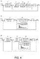
- the part (a) in the upper part of FIG. 4 shows a basic structure (hereinafter simply referred to as "basic structure") for explaining the simulation system corresponding to a mechanical configuration of the control system shown in FIG. 1 .
- the part (b) in the middle part of FIG. 4 shows one form of the simulation system 130
- the part (c) in the lower part shows other form of the simulation system 130.
- the part (b) in the middle part and the part (c) in the lower part of FIG. 4 show the structure of the simulation system 130 adopted by the processing device 10.
- the basic structure shown in the part (a) in the upper part of FIG. 4 corresponds to the mechanical configuration of the control system shown in FIG. 1 and includes a model position control unit 51, a model speed control unit 52, a model current control unit 53, and a mechanical model unit 54.
- the model position control unit 51 corresponds to the position controller 41 of the servo driver 4
- the model speed control unit 52 corresponds to the speed controller 42 of the servo driver 4
- the model current control unit 53 corresponds to the current controller 43 of the servo driver 4
- the mechanical model unit 54 corresponds to the control object 6.
- a positional deviation between a position command pcmd and a response position psim which is a system output is input to the model position control unit 51, and a speed command vcmd is output.
- a speed deviation between the speed command vcmd and a response speed vsim which is an output of the mechanical model unit 54 is input to the model speed control unit 52, and a torque command ⁇ cmd is output.
- the torque command ⁇ cmd is input to the model current control unit 53, and a current command ccmd is output.
- the current command ccmd is input to the mechanical model unit 54, and the above-mentioned response speed vsim, and the above-mentioned response position psim which is an integration result of the response speed vsim, are output.
- a control structure shown in the part (b) of FIG. 4 which is one form of the simulation system, is a structure in which the model speed control unit 52, the model current control unit 53 and the mechanical model unit 54 in the basic structure shown in the part (a) of FIG. 4 are replaced with a speed system impulse response model unit 520 which is a predetermined control block structure, and a feedback system using the model position control unit 51 and the speed system impulse response model unit 520 as forward elements is included.
- the speed system impulse response model unit 520 has, as an impulse response model, information relating to a response (impulse response) at the time when an impulse signal of the speed command is input to the one mechanical configuration. That is, it can be said that the impulse response information owned by the speed system impulse response model unit 520 is speed impulse response-related information that reflects characteristics of the speed controller 42, the current controller 43 and the control object 6 which are the actual control system-side mechanical configuration. Generation of the impulse response information can be realized by the prior art.
- An output with respect to an arbitrary input to the speed system impulse response model unit 520 can be calculated by convolution processing of the arbitrary input and the impulse response information owned by the speed system impulse response model unit 520.
- the simulation system 130 has the control structure shown in the part (b) of FIG. 4 , the positional deviation between the position command pcmd and the response position psim which is the system output is input to the model position control unit 51, and the speed command vcmd is calculated. Then, when the speed command vcmd is input to the speed system impulse response model unit 520, the response speed vsim corresponding to the speed command vcmd is calculated by convolution processing, and the above-mentioned response position psim which is the integration result of the response speed vsim is further calculated.
- the calculations of each control value in the simulation system 130 are performed by a first response calculation unit 134A and a second response calculation unit 134B included in the calculation unit 134, and the details thereof are described later.
- a control structure shown in the part (c) of FIG. 4 which is other form of the simulation system, is a structure in which the model current control unit 53 and the mechanical model unit 54 in the basic structure shown in the part (a) of FIG. 4 are replaced with a current system impulse response model unit 530 which is a predetermined control block structure, and a speed feedback system using the model speed control unit 52 and the current system impulse response model unit 530 as forward elements as well as a position feedback system using the model position control unit 51 and the speed feedback system as forward elements are included.
- the current system impulse response model unit 530 has, as an impulse response model, information relating to a speed response (speed impulse response) at the time when an impulse signal of the torque command is input to the one mechanical configuration.
- Generation of the impulse response information can be realized by the prior art. Generally, it is realized by performing an inverse Fourier transform on a frequency transfer function relating to the model current control unit 53 and the mechanical model unit 54 in the control structure shown in the part (c) of FIG. 4 .
- An output with respect to an arbitrary input to the current system impulse response model unit 530 can be calculated by convolution processing of the arbitrary input and the impulse response information owned by the current system impulse response model unit 530.
- the positional deviation between the position command pcmd and the response position psim which is the system output is input to the model position control unit 51, and the speed command vcmd is calculated. Then, the speed deviation between the speed command vcmd and the response speed vsim is input to the model speed control unit 52, and the torque command ⁇ cmd is calculated.
- the response speed vsim corresponding to the torque command ⁇ cmd is calculated by convolution processing, and the above-mentioned response position psim which is the integration result of the response speed vsim is further calculated.
- the calculations of each control value in the simulation system 130 are also performed by the first response calculation unit 134A and the second response calculation unit 134B included in the calculation unit 134, and the details thereof are described later.
- the simulation system 130 has an impulse response model unit as a control block corresponding to a mechanical configuration including at least the control object 6 which is to be simulated, and has a feedback system using at least the impulse response model unit as a forward element.
- the holding unit 131 is a functional unit holding the impulse response information included in the impulse response model unit included in the simulation system 130.
- the calculation unit 134 is a functional unit receiving the impulse response information held by the holding unit 131, and performing simulation processing in accordance with the simulation system 130, that is, calculation of the response speed vsim and the response position psim which are response results of the simulation system 130.
- the calculation unit 134 has the first response calculation unit 134A and the second response calculation unit 134B as sub functional units.
- the first response calculation unit 134A is a sub functional unit calculating the response speed vsim relating to the convolution processing utilizing the impulse response information owned by the speed system impulse response model unit 520 of the part (b) of FIG. 4 , or a sub functional unit calculating the response speed vsim relating to the convolution processing utilizing the impulse response information owned by the current system impulse response model unit 530 of the part (c) of FIG. 4 .
- the second response calculation unit 134B is a sub functional unit calculating a time response to a command value input to the simulation system 130, that is, the response position psim, by using a calculation result of the first response calculation unit 134A, that is, the response speed vsim calculated by convolution processing.
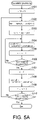
- a flow of calculation processing by the calculation unit 134 for calculating the time response psim of the position and the time response vsim of the speed when a predetermined position command for simulation processing is input to a simulation system is schematically shown in: (1) a case where the simulation system 130 is the control structure shown in the part (b) of FIG. 4 , and ( 2 ) a case where the simulation system 130 is the control structure shown in the part (c) of FIG. 4 .
- the flow of the calculation processing in this case is explained in accordance with a flowchart shown in FIG. 5A . Moreover, the calculation processing is executed in the case where a command value for simulation processing is received by the input unit 11.
- a parameter m and a parameter n are initialized.
- a positional deviation perr which is the deviation between the position command pcmd and the response position psim is calculated.
- S103 by multiplying the positional deviation perr by the position proportional gain Kpp, the speed command vcmd is calculated.
- the speed command vcmd is used as an input to the speed system impulse response model unit 520, and convolution processing for calculating the response speed vsim which is an output from the speed system impulse response model unit 520 is performed.
- an operation in accordance with the following Equation 1 is performed; next, in S105, the parameter n is incremented.
- vsim m + n vsim m + n + vcmd ⁇ gimp n
- gimp[n] is the impulse response information owned by the speed system impulse response model unit 520. This information means a speed response to an impulse-like speed input.
- S106 it is determined whether or not the parameter n has reached an upper limit, that is, whether or not an upper limit repetition number for repeating the operation by Equation 1 according to length of the impulse response information gimp has been reached. If a negative determination is made in S106, the processing in and after S104 is repeated; if a positive determination is made, the processing proceeds to S107.
- the response speed vsim calculated by the convolution processing is integrated, and the response position psim is calculated.
- the parameter m is incremented.
- it is determined whether or not the parameter m has reached an upper limit that is, whether or not an upper limit repetition number for repeating the processing from S102 to S109 according to time (desired response time) for which simulation is intended to be performed by the calculation processing has been reached. If a negative determination is made in S110, the processing in and after S102 is repeated; if a positive determination is made, the present calculation processing is ended.
- the flow of the calculation processing in this case is explained in accordance with a flowchart shown in FIG. 5B . Moreover, the calculation processing is executed in the case where an input value for simulation processing is received by the input unit 11.
- the parameter m and the parameter n are initialized.
- the positional deviation perr which is the deviation between the position command pcmd and the response position psim is calculated.
- the speed command vcmd is calculated.
- a speed deviation verr which is the deviation between the speed command vcmd and the response speed vsim is calculated. Further, in S205, the speed deviation verr is integrated and an integral amount ⁇ is calculated; in S206, the torque command ⁇ cmd is calculated in accordance with the following Equation 3.
- ⁇ cmd Kvp ⁇ verr + ⁇ ⁇ Kvi
- the torque command ⁇ cmd is used as an input to the current system impulse response model unit 530, and convolution processing for calculating the response speed vsim which is an output from the current system impulse response model unit 530 is performed.
- an operation in accordance with the following Equation 4 is performed; next, in S208, the parameter n is incremented.
- vsim m + n vsim m + n + ⁇ cmd ⁇ gimp ′ n
- gimp'[n] is the impulse response information owned by the current system impulse response model unit 530. This information means a speed response to an impulse-like torque input.
- the response speed vsim calculated by the convolution processing is integrated, and the response position psim is calculated.
- the parameter m is incremented.
- it is determined whether or not the parameter m has reached an upper limit that is, whether or not an upper limit repetition number for repeating the processing from S202 to S212 according to time (desired response time) for which simulation is intended to be performed by the calculation processing has been reached. If a negative determination is made in S213, the processing in and after S202 is repeated; if a positive determination is made, the present calculation processing is ended.
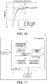
- FIG. 6 shows a simulation result when the calculation processing shown in FIG. 5B is executed.
- the horizontal axis in FIG. 6 represents time, and the vertical axis represents the response position psim.
- line L1 in FIG. 6 represents a transition of the position command pcmd
- line L2 represents a transition of the response position psim by the above-mentioned calculation processing.
- line L3 represents a transition of a position calculated in accordance with the prior art, specifically, in the case represented by an impulse response model unit (hereinafter referred to as "conventional impulse response model unit") corresponding to the entire basic structure including the model position control unit 51, the model speed control unit 52, the model current control unit 53, the machine model unit 54 and the feedback loop shown in the part (a) of FIG. 4 , a transition of a position calculated by convolution processing using the position command pcmd input to the conventional impulse response model unit and the impulse response information owned by the conventional impulse response model unit.
- an impulse response model unit hereinafter referred to as "conventional impulse response model unit”
- a time axis of the impulse response information owned by the impulse response model unit is limited information.
- a response result cannot completely follow the position command, and a steady-state deviation remains, resulting in a decrease in simulation accuracy.
- the time axis in the impulse response information should be as long as possible; however, in that case, since capacity of the impulse response information may increase, and calculation time for simulation may increase, it is not practical.
- the response result suitably follows the position command, and the steady-state deviation is largely eliminated.
- the convolution processing is performed using the impulse response information owned by the current system impulse response model unit 530 using the torque command ⁇ cmd as an input, and the feedback system using the current system impulse response model unit 530 and the model speed control unit 52 as forward elements is included in the simulation system 130. That is, in the calculation of the response position psim, combined processing of the calculations by the first response calculation unit 134A and the calculation by the second response calculation unit 134B is performed.
- the steady-state deviation at the response position can be effectively eliminated.
- the response position by utilizing the convolution processing by using the impulse response information, there is no need to set a physical model of the control object for the calculation, and therefore a highly accurate response result more compliant with the actual machine can be obtained.
- the third calculation processing to be executed by the processing device 10 is explained based on a flowchart shown in FIG. 7 .
- the calculation processing is also executed by the calculation unit 134 of the simulation unit 13, wherein substantially the same processing as those in the calculation processing shown in FIG. 5A are denoted by the same reference numerals, and the detailed description thereof is omitted.
- the present embodiment is similarly applicable to the calculation processing shown in FIG. 5B .
- the processing in S301 is performed next.
- S301 a driving state of the control object 6 is acquired.
- the impulse response information used in the convolution processing performed in S107 to S109 is selected or synthesized.
- This selection of the impulse response information gimp means to select the impulse response information to be used for convolution processing from among a plurality of pieces of impulse response information owned by the holding unit 131.
- the synthesis of the impulse response information gimp means to utilize the plurality of pieces of impulse response information owned by the holding unit 131 to generate new impulse response information to be used for convolution processing. Accordingly, the selected or synthesized impulse response information will be used as the impulse response information gimp for the speed system impulse response model unit 520 in S104 subsequent to S302.
- the processing in S301 and S302 is performed by the first response calculation unit 134A.
- the convolution processing is performed; after that, when the processing in and after S102 is performed again after a negative determination is made in S110, the impulse response information gimp to be used in the next convolution processing is selected or synthesized again based on the driving state of the control object 6 at that time. Accordingly, in the calculation processing shown in FIG. 7 , since the impulse response information gimp that properly reflects the driving state of the control object 6 is used, a time response of a simulation system can be more accurately calculated.
- the load device 3 is set as a conveyance device having a table configured to reciprocate via a ball screw and conveying a predetermined load in one direction.
- the load device 3 conveys the predetermined load in one direction by the motor 2 rotating positively, and the load device 3 moves in a reverse direction in a state without the predetermined load by the motor 2 rotating negatively.
- load inertia is different between when the motor 2 is rotating positively and when the motor 2 is rotating negatively.
- the time response of the simulation system 130 is calculated using the impulse response information that suitably reflects the driving state of the actual control object 6. As a result, accuracy of calculation of the time response of the simulation system 130 is improved.
- Example 2-2 as in Example 2-1, the load device 3 is set as a conveyance device having a table configured to reciprocate via a ball screw. Since the ball screw is relatively long, according to the position of the table to which a nut of the ball screw is attached, mechanical frequency characteristics of the load device 3 vary greatly. Therefore, in order to obtain a highly accurate simulation result, the holding unit 131 has a plurality of pieces of impulse response information gimp of the control object 6 according to the table position at the ball screw, and, with the table position as the driving state of the control object 6, the impulse response information gimp suitable for the driving state is selected.
- a movable range of the load device 3 at the ball screw from a starting point to an end point is divided into two sections R1 and R2.
- the holding unit 131 holds two pieces of impulse response information gimp1 and gimp2 respectively corresponding to each section, and the table position calculated from the position of the motor 2 is taken as the driving state of the control object 6.
- the table position belongs to R1 and R2, respectively, the impulse response information gimp1 and the impulse response information gimp2 are respectively selected, and the impulse response information used for the convolution processing in S104 to S106 is switched.
- the impulse response information according to the table position is selected, and the impulse response information used for the convolution processing in S104 to S106 will be switched.
- the time response of the simulation system 130 is calculated using the impulse response information that suitably reflects the driving state of the actual control object 6. As a result, accuracy of calculation of the time response of the simulation system 130 is improved.
- the load device 3 is a conveyance device having a table configured to reciprocate via a ball screw.
- the holding unit 131 holds the impulse response information gimp1 when the table is located at point X1, and further holds the impulse response information gimp2 when the table is located at point X2.
- the point X1 is a point near the starting point side of the ball screw
- the point X2 is a point near the end point side of the ball screw.
- the table position calculated from the position of the motor 2 is taken as the driving state of the control object 6. Accordingly, the points X1 and X2 correspond to reference driving states of the present invention.
- the impulse response information used for the convolution processing in S104 to S106 is selected from among the impulse response information held by the holding unit 131. Specifically, if the table position is between the starting point of the ball screw and the point X1, the impulse response information gimp1 is selected; if the table position is between the end point of the ball screw and the point X2, the impulse response information gimp2 is selected.
- the impulse response information is selected based on distances ⁇ X1 and ⁇ X2 between the table position and the points X1 and X2 respectively. Specifically, if the distance ⁇ X1 between the table and the point X1 is shorter than the distance ⁇ X2 between the table and the point X2, the impulse response information gimp1 is selected; if the distance ⁇ X1 between the table and the point X1 is equal to or longer than the distance ⁇ X2 between the table and the point X2, the impulse response information gimp2 is selected.
- the distances ⁇ X1 and ⁇ X2 between the table position and the points X1 and X2 respectively may be evaluated in accordance with another evaluation method, and either of the impulse response information gimp1 and the impulse response information gimp2 may be selected based on the evaluation result.
- the time response of the simulation system 130 is calculated using the impulse response information that suitably reflects the driving state of the actual control object 6. As a result, accuracy of calculation of the time response of the simulation system 130 is improved.
- the selection of the plurality of pieces of impulse response information held by the holding unit 131 and the switching of the impulse response information for convolution processing are performed with the tip position Pf of the manipulator device, instead of the rotation angles ⁇ 1 and ⁇ 2, as the driving state of the control object 6.
- the plurality of pieces of impulse response information held by the holding unit 131 are held in a state associated with the tip position Pf of the manipulator device.
- the tip position Pf is uniquely determined.
- the tip position is used as the driving state of the control object 6, for example, for the tip position Pf of the manipulator device, the impulse response information that corresponds to a tip position among a plurality of tip positions associated with the held plurality of pieces of impulse response information which is closest to the tip position during the calculation processing is selected, and the selected impulse response information is used for the convolution processing in S104 to S106 of the calculation processing.
- an evaluation method for selecting the impulse response information is not limited to the above-mentioned method.
- the time response of the simulation system 130 is also calculated using the impulse response information that suitably reflects the driving state of the actual control object 6. As a result, accuracy of calculation of the time response of the simulation system 130 is improved.
- the impulse response information used in the convolution processing of the calculation processing shown in FIG. 7 is one piece of impulse response information selected from among the plurality of pieces of impulse information held by the holding unit 131, based on the driving state of the control object 6, and according to this selection, the impulse response information used in the convolution processing will be switched.
- the impulse response information when the impulse response information is switched, depending on the degree of difference in the impulse response information before and after switching, a response calculated by the calculation unit 134 may vibrate or become unstable. Therefore, in the present embodiment, in the case of switching from one piece of impulse response information held by the holding unit 131 to another piece of impulse response information, the switching may be performed gradually rather than suddenly.
- the time response of the simulation system 130 is more stably calculated using the impulse response information that suitably reflects the driving state of the actual control object 6. As a result, accuracy of calculation of the time response of the simulation system 130 is improved.
- FIG. 10 shows a simulation result when the calculation processing in Example 2-3 is executed.
- the horizontal axis in FIG. 10 represents time, and the vertical axis represents the response position psim.
- line L5 in FIG. 10 represents a transition of the position command pcmd
- line L6 represents a transition of a response position in the case where selection and switching of the impulse response information are not performed
- line L7 represents a transition of the response position in the case where the selection and switching of the impulse response information are performed.
- line L8 represents a transition of the actual response position.
- FIG. 11 a second functional block diagram relating to the processing device 10 is shown in FIG. 11 .
- the processing device 10 of the present embodiment further includes an impulse response generation unit 132.
- the impulse response generation unit 132 is a functional unit utilizing the impulse response information held by the holding unit 131 to generate new impulse response information, and the generated impulse response information will be newly held by the holding unit 131.
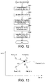
- FIG. 12 is a flowchart of the first generation processing
- FIG. 13 is a diagram as an image of a norm ratio for generating new impulse response information in the generation processing
- FIG. 14 is a diagram showing a simulation result by the processing device 10 obtained utilizing the new impulse response information generated by the generation processing.
- the generation processing shown in FIG. 12 is executed with a generation instruction input by the user via the input unit 11 being used as a trigger.
- This generation instruction contains what kind of impulse response information is newly generated and a generation condition for the new impulse response information.
- One example of the generation condition is a new driving state different from the driving state of the control object 6 corresponding to the already held impulse response information, and contains information relating to the driving state (hereinafter referred to as "generation object driving state") of the control object 6 corresponding to the new impulse response information generated by the generation processing.
- the impulse response generation unit 132 extracts frequency characteristic information from the information held by the holding unit 131.
- the holding unit 131 holds a plurality of pieces of impulse response information.
- the holding unit 131 also holds, together with the plurality of pieces of impulse response information, the frequency characteristic information relating to the frequency transfer function, which is basic information for generating each piece of impulse response information via the inverse Fourier transform. In the holding operation, the relevance between impulse response information and the corresponding frequency characteristic information is maintained.
- the frequency characteristic information corresponding to the four pieces of impulse response information is extracted in S401.
- a ratio of a norm (distance) between a generation object driving state input as a generation condition and the driving state of the control object 6 corresponding to each piece of the impulse response information currently held in the holding unit 131 is calculated.
- the calculation of the ratio of the norm is explained based on FIG. 13.
- FIG. 13 shows the driving state of the control object 6 corresponding to the four pieces of impulse response information currently held in the holding unit 131, wherein output positions of the load device 3 are represented by four white circles (points (3, 3), (6, 3), (3, 6), and (6, 6)).
- new frequency characteristic information corresponding to the generation object driving state (in the example shown in FIG. 13 , the new point (5, 5)) contained in the generation condition is calculated in accordance with the following Equation 7 using the ratios of the norms calculated in S402.
- NewFw ⁇ RNorm ⁇ Fw
- Equation 7 is an equation calculating new frequency characteristic information by weighted averaging existing frequency characteristic information based on a ratio of a norm.
- the new impulse response information corresponding to the generation object driving state (in the example shown in FIG. 13 , the new point (5, 5)) is generated.
- the newly generated impulse response information and the frequency characteristic information as the basic information therefor are associated with each other and held in the holding unit 131. Accordingly, the calculation unit 134 can use the new impulse response information for the convolution processing in the calculation processing shown in FIG. 5A , FIG. 5B and FIG. 7 . Accordingly, even if the user does not directly measure or acquire the impulse response information corresponding to the generation object driving state, since the desired impulse response information can be generated by utilizing the existing holding information, it is possible to greatly reduce the effort required to acquire a highly accurate simulation result.
- FIG. 14 a simulation result of the speed response by the calculation processing shown in FIG. 5B in the case where the new impulse response information is generated by the generation processing in Example 3-1 is shown.
- the impulse response information in the case (model 1) where the load inertia is 0.00064 kgm 2 and the impulse response information in the case (model 2) where the load inertia is 0.0064 kgm 2 are held together with the load inertia values which is the driving state thereof.
- These pieces of impulse response information are information obtained by measuring the mechanical frequency characteristics of the actual machine.
- an impulse response model is generated in the case (new model) where the load inertia is 0.0019 kgm 2 , and is newly held in holding unit 131.
- FIG. 14 a speed response of each model is calculated by calculation processing and is shown in FIG. 14 .
- the horizontal axis in FIG. 14 represents time, and the vertical axis represents response speed.
- Line L11 in FIG. 14 represents a transition of the speed command vcmd
- line L12 represents a transition of the speed response corresponding to the model 1
- line L13 represents a transition of the speed corresponding to the model 2
- line L14 represents a transition of the speed of the new model.
- line L15 represents an actual transition of the speed of the actual machine whose load inertia is 0.0019 kgm 2 as in the new model.
- FIG. 15 is a flowchart of the second generation processing. Similarly to the generation processing shown in FIG. 12 , the generation processing shown in FIG. 15 is also executed with a generation instruction from the user input via the input unit 11 being used as a trigger, and this generation instruction contains the information relating to the generation object driving state as the generation condition for the new impulse response information.
- the impulse response generation unit 132 extracts a plurality of pieces of impulse response information from the information held by the holding unit 131, as in S401 mentioned above. After that, in S502, by subjecting the plurality of pieces of impulse response information extracted in S501 to weighted averaging based on the generation object driving state, new impulse response information is generated. For example, with respect to the two pieces of impulse response information corresponding to the model 1 and the model 2 shown in Example 3-1 mentioned above, a ratio for weighted averaging is determined based on the load inertia of the new model, and the ratio is utilized to generate the impulse response information for the new model. The ratio for weighted averaging can be determined by properly evaluating a correlation between the load inertia of the model 1 and the model 2 and the load inertia of the new model.
- the calculation unit 134 can use the new impulse response information for the convolution processing in the calculation processing shown in FIG. 5A , FIG. 5B and FIG. 7 . Accordingly, even if the user does not directly measure or acquire the impulse response information corresponding to the generation object driving state, since the desired impulse response information can be generated by utilizing the existing holding information, it is possible to greatly reduce the effort required to acquire a highly accurate simulation result. In addition, since frequency characteristic information is not utilized as in Example 3-1, it is possible to generate new impulse response information relatively easily.
Landscapes
- Engineering & Computer Science (AREA)
- Physics & Mathematics (AREA)
- Power Engineering (AREA)
- Theoretical Computer Science (AREA)
- General Physics & Mathematics (AREA)
- Evolutionary Computation (AREA)
- Computer Hardware Design (AREA)
- Geometry (AREA)
- General Engineering & Computer Science (AREA)
- Medical Informatics (AREA)
- Software Systems (AREA)
- Health & Medical Sciences (AREA)
- Automation & Control Theory (AREA)
- Computer Vision & Pattern Recognition (AREA)
- Artificial Intelligence (AREA)
- Control Of Electric Motors In General (AREA)
- Feedback Control In General (AREA)
Claims (12)
- Simulationsvorrichtung (10), die konfiguriert ist, ein Steuerungssystem zu simulieren, das ein Steuerungsobjekt (6) aufweist, das einen Motor (2), der eine Lastvorrichtung antreibt, und einen Servoantrieb, der den Motor (2) steuert, umfasst, um auf der Basis einer simulierten Antwort der Lastvorrichtung einen Motorsteuerungsbefehl zu bestimmen, wobei die Simulationsvorrichtung (10) Folgendes umfasst:ein Simulationssystem (130), das ein vorgegebenes Rückkopplungssystem umfasst, das als ein Weiterleitungselement wenigstens eine vorgegebene Steuerungsblockstruktur umfasst, die einer vorgegebenen vorrichtungsseitigen Konfiguration entspricht, die das Steuerungsobjekt (6) umfasst und eine Impulsantwortmodelleinheit (520, 530) aufweist;eine Halteeinheit (131), die konfiguriert ist, Impulsantwortinformationen, die in der Impulsantwortmodelleinheit (520, 530) enthalten sind und die Informationen über eine Impulsantwort sind, die sich auf die vorgegebene vorrichtungsseitige Konfiguration bezieht, zur Berechnung zu speichern;eine erste Antwortberechnungseinheit (134A), die konfiguriert ist, eine Zeitantwort der vorgegebenen vorrichtungsseitigen Konfiguration auf eine vorgegebene eingegebene Impulsantwort des Motorsteuerungsbefehls durch eine Faltungsverarbeitung unter Verwendung der Impulsantwortinformationen zur Berechnung, die aus der Halteeinheit (131) extrahiert werden, und des vorgegebenen Eingangswerts zu berechnen; undeine zweite Antwortberechnungseinheit (134B), die konfiguriert ist, eine Antwort des Simulationssystems (130) auf einen Steuerungsbefehl, der beim Simulationssystem (130) eingegeben wird, unter Verwendung der Zeitantwort der vorgegebenen vorrichtungsseitigen Konfiguration, die durch die erste Antwortberechnungseinheit (134A) berechnet wurde, zu berechnen; wobeidie zweite Antwortberechnungseinheit (134B) in dem vorgegebenen Rückkopplungssystem konfiguriert ist, die Antwort des Simulationssystems (130) entsprechend einem Verfahren zum Rückkoppeln der Zeitantwort der vorgegebenen vorrichtungsseitigen Konfiguration oder eines vorgegebenen Antwortergebnisses, das aus der Zeitantwort berechnet wurde, bei einer Eingangsseite des Weiterleitungselements zu berechnen,die Impulsantwort eine Impulsantwort auf einen aktuellen Befehl (ccmd) ist,das vorgegebene Rückkopplungssystem ein Geschwindigkeitsrückkopplungssystem ist und als das Weiterleitungselement in dem vorgegebenen Rückkopplungssystem die vorgegebene Steuerungsblockstruktur und eine Geschwindigkeitssteuerungsblockstruktur, die sich auf eine Geschwindigkeitskompensation bezieht, umfasst, unddie zweite Antwortberechnungseinheit (134B) konfiguriert ist, eine Zeitantwort des Simulationssystems (130) so zu berechnen, dass eine Geschwindigkeitsantwort, die durch die erste Antwortberechnungseinheit (134A) berechnet wird, der Geschwindigkeitssteuerungsblockstruktur entsprechend dem Rückkopplungsverfahren rückgekoppelt wird.
- Simulationsvorrichtung (10) nach Anspruch 1, wobeidie Impulsantwort eine Impulsantwort auf einen Geschwindigkeitsbefehl (vcmd) ist;das vorgegebene Rückkopplungssystem ein Positionsrückkopplungssystem ist und als das Weiterleitungselement in dem vorgegebenen Rückkopplungssystem die vorgegebene Steuerungsblockstruktur und eine Positionssteuerungsblockstruktur, die sich auf eine Positionskompensation bezieht, umfasst;die zweite Antwortberechnungseinheit (134B) konfiguriert ist, eine Zeitantwort des Simulationssystems (130) so zu berechnen, dass eine Positionsantwort auf der Basis der Geschwindigkeitsantwort, die durch die erste Antwortberechnungseinheit (134A) berechnet wird, der Positionssteuerungsblockstruktur entsprechend dem Rückkopplungsverfahren rückgekoppelt wird.
- Simulationsvorrichtung (10) nach einem der Ansprüche 1 bis 2, wobeidie Halteeinheit (131) konfiguriert ist, mehrere Muster von Impulsantwortinformationen als Impulsantwortinformationen zur Berechnung zu speichern;die erste Antwortberechnungseinheit (134A) konfiguriert ist, vorgegebene Impulsantwortinformationen aus den mehreren Mustern von Impulsantwortinformationen, die die Halteeinheit (131) besitzt, auf der Basis eines Fahrzustands des Steuerungsobjekts (6) auszuwählen, und die Faltungsverarbeitung unter Verwendung der ausgewählten vorgegebenen Impulsantwortinformationen und des vorgegebenen Eingangswerts ausführt.
- Simulationsvorrichtung (10) nach Anspruch 3, wobeidie mehreren Muster von Impulsantwortinformationen jeweils zu mehreren Referenz-Fahrzuständen gehören, die unterschiedliche Fahrzustände des Steuerungsobjekts (6) sind;die erste Antwortberechnungseinheit (134A) konfiguriert ist, die vorgegebenen Impulsantwortinformationen auf der Basis einer Korrelation zwischen dem Fahrzustand des Steuerungsobjekts (6) und jedem der mehreren Referenz-Fahrzustände auszuwählen.
- Simulationsvorrichtung (10) nach Anspruch 4, wobeidas Steuerungsobjekt (6) eine fahrende Objektmaschine umfasst, die durch mehrere Motoren automatisch angetrieben wird;die mehreren Muster von Impulsantwortinformationen jeweils zu den mehreren Referenz-Fahrzuständen gehören, die sich auf einen Statuswert eines vorgegebenen Abschnitts der fahrenden Objektmaschine beziehen;die erste Antwortberechnungseinheit (134A) konfiguriert ist, die vorgegebenen Impulsantwortinformationen auf der Basis einer Korrelation zwischen dem Statuswert des vorgegebenen Abschnitts der fahrenden Objektmaschine und jedem der mehreren Referenz-Fahrzustände auszuwählen.
- Simulationsvorrichtung (10) nach einen der Ansprüche 1 bis 2, wobeidie Halteeinheit (131) konfiguriert ist, mehrere Muster von Impulsantwortinformationen als die Impulsantwortinformationen zur Berechnung zu speichern;die erste Antwortberechnungseinheit (134A) konfiguriert ist, wenigstens zwei Teile von Impulsantwortinformationen aus den mehreren Mustern von Impulsantwortinformationen, die die Halteeinheit (131) besitzt, auf der Basis eines Fahrzustands des Steuerungsobjekts (6) auszuwählen, neue Impulsantwortinformationen entsprechend dem Fahrzustand des Steuerungsobjekts (6) aus den ausgewählten wenigstens zwei Teilen von Impulsantwortinformationen zu synthetisieren und die Faltungsverarbeitung unter Verwendung der synthetisierten neuen Impulsantwortinformationen und des vorgegebenen Eingangswerts auszuführen.
- Simulationsvorrichtung (10) nach einem der Ansprüche 1 bis 2, wobeidie Halteeinheit (131) konfiguriert ist, als die Impulsantwortinformationen zur Berechnung mehrere Muster von Impulsantwortinformationen, die zu mehreren Referenz-Fahrzuständen gehören, die unterschiedliche Fahrzustände des Steuerungsobjekts (6) sind, zu speichern, und Frequenzeigenschaftsinformationen, die jedem der mehreren Muster von Impulsantwortinformationen zugeordnet werden, und die mehreren Teile von Referenz-Fahrzuständen enthält, und die verschiedenen Impulsantwortinformationen erzeugen kann;wobei die Simulationsvorrichtung (10) ferner Folgendes umfasst:eine Einheit zum Erzeugen von Impulsantwortinformationen, die auf der Basis einer Korrelation zwischen einem Fahrzustand des Steuerungsobjekts (6) und jedem von wenigstens zwei der mehreren Referenz-Fahrzustände aus den Frequenzeigenschaftsinformationen, die zu den wenigstens zwei Referenz-Fahrzuständen gehören, neue Frequenzeigenschaftsinformationen, die dem Fahrzustand des Steuerungsobjekts (6) entsprechen, erzeugt, und neue Impulsantwortinformationen, die dem Fahrzustand des Steuerungsobjekts (6) entsprechen, auf der Basis der erzeugten neuen Frequenzeigenschaftsinformationen erzeugt;wobei die erste Antwortberechnungseinheit (134A) konfiguriert ist, die Faltungsverarbeitung unter Verwendung der neuen Impulsantwortinformationen, die durch die Einheit zum Erzeugen der Impulsantwortinformationen erzeugt wurden, und des vorgegebenen Eingangswerts auszuführen.
- Simulationsvorrichtung (10) nach Anspruch 7, wobei
auf der Basis der Korrelation zwischen dem Fahrzustand des Steuerungsobjekts (6) und jedem der wenigstens zwei Referenz-Fahrzustände die Einheit zum Erzeugen von Impulsantwortinformationen konfiguriert ist, die neuen Frequenzeigenschaftsinformationen durch Bilden eines gewichteten Mittelwerts der Frequenzeigenschaftsinformationen, die zu den wenigstens zwei Referenz-Fahrzuständen gehören, zu erzeugen. - Simulationsvorrichtung (10) nach einem der Ansprüche 1 bis 2, die ferner Folgendes umfasst:eine Einheit zum Erzeugen von Impulsantwortinformationen, die konfiguriert ist, wenigstens zwei Teile von Impulsantwortinformationen aus mehreren Mustern von Impulsantwortinformationen, die die Halteeinheit (131) besitzt, auszuwählen, und die konfiguriert ist, neue Impulsantwortinformationen aus den ausgewählten wenigstens zwei Teilen der Impulsantwortinformationen zu erzeugen,wobei die Halteeinheit (131) konfiguriert ist, die neuen Impulsantwortinformationen, die durch die Einheit zum Erzeugen von Impulsantwortinformationen erzeugt wurden, zu speichern.
- Simulationsvorrichtung (10) nach Anspruch 9, wobei
die Einheit zum Erzeugen von Impulsantwortinformationen konfiguriert ist, die neuen Impulsantwortinformationen durch Bilden des gewichteten Mittelwerts der wenigstens zwei Teile von Impulsantwortinformationen zu erzeugen. - Simulationsverfahren zum Simulieren eines Steuerungssystems, das ein Steuerobjekt (6) aufweist, das einen Motor (2), der eine Lastvorrichtung antreibt, und einen Servoantrieb, der den Motor (2) steuert, umfasst, um auf der Basis einer simulierten Antwort der Lastvorrichtung einen Motorsteuerungsbefehl zu bestimmen, wobei das Simulationsverfahren auf der Simulationsvorrichtung nach Anspruch 1 läuft und die folgenden Schritte umfasst:Berechnen einer Zeitantwort einer vorgegebenen vorrichtungsseitigen Konfiguration, die das Steuerungsobjekt (6) umfasst, auf eine vorgegebene eingegebenen Impulsantwort eines Motorsteuerungsbefehls durch Faltungsverarbeitung unter Verwendung von Impulsantwortinformationen zum Berechnen, die Informationen bezüglich einer Impulsantwort sind, die sich auf die vorgegebene vorrichtungsseitige Konfiguration und den vorgegebenen Eingangswert bezieht;Berechnen einer Antwort des Simulationssystems (130) auf einen Steuerungsbefehl, der beim Simulationssystem (130) eingegeben wurde, unter Verwendung der Zeitantwort der vorgegebenen vorrichtungsseitigen Konfiguration, die im Berechnungsschritt durch die Faltungsverarbeitung berechnet wurde, auf der Basis eines Simulationssystems (130), das ein vorgegebenes Rückkopplungssystem umfasst, das als Weiterleitungselement wenigstens eine vorgegebene Steuerungsblockstruktur entsprechend der vorgegebenen vorrichtungsseitigen Konfiguration aufweist;Berechnen im vorgegebenen Rückkopplungssystem der Antwort des Simulationssystems (130) entsprechend einem Verfahren einer Rückkopplung der Zeitantwort der vorgegebenen vorrichtungsseitigen Konfiguration oder eines vorgegebenen Antwortergebnisses, das aus der Zeitantwort berechnet wurde, bei einer Eingangsseite des Weiterleitungselements; undBerechnen eine Zeitantwort des Simulationssystems (130), so dass eine Geschwindigkeitsantwort der Geschwindigkeitssteuerungsblockstruktur entsprechend dem Rückkopplungsverfahren rückgekoppelt wird; wobeidie Impulsantwort eine Impulsantwort auf einen aktuellen Befehl (ccmd) ist, unddas vorgegebene Rückkopplungssystem ein Geschwindigkeitsrückkopplungssystem ist und als das Weiterleitungselement in dem vorgegebenen Rückkopplungssystem die vorgegebene Steuerungsblockstruktur und eine Geschwindigkeitssteuerungsblockstruktur, die sich auf eine Geschwindigkeitskompensation bezieht, umfasst.
- Simulationsprogramm, das auf der Simulationsvorrichtung nach Anspruch 1 zum Simulieren eines Steuerungssystems läuft, das ein Steuerungsobjekt (6), das einen Motor (2) aufweist, der eine Lastvorrichtung antreibt, und einen Servoantrieb, der den Motor (2) steuert, umfasst, um einen Motorsteuerungsbefehl auf der Basis einer simulierten Antwort der Lastvorrichtung zu bestimmen, und wobei die folgenden Schritte ausgeführt werden:einen Schritt zum Berechnen einer Zeitantwort einer vorgegebenen vorrichtungsseitigen Konfiguration, die das Steuerungsobjekt (6) umfasst, auf eine vorgegebene eingegebene Impulsantwort eines Motorsteuerungsbefehls durch Faltungsverarbeitung unter Verwendung von Impulsantwortinformationen zum Berechnen, die Informationen bezüglich einer Impulsantwort sind, die sich auf die vorgegebene vorrichtungsseitige Konfiguration und den vorgegebenen Eingangswert bezieht;einen Schritt zum Berechnen einer Antwort des Simulationssystems (130) auf einen Steuerungsbefehl, der beim Simulationssystem (130) eingegeben wird, unter Verwendung der Zeitantwort der vorgegebenen vorrichtungsseitigen Konfiguration, die im Berechnungsschritt durch die Faltungsverarbeitung berechnet wurde, auf der Basis eines Simulationssystems (130), das ein vorgegebenes Rückkopplungssystem umfasst, das als Weiterleitungselement wenigstens eine vorgegebene Steuerungsblockstruktur entsprechend der vorgegebenen vorrichtungsseitigen Konfiguration aufweist;einen Schritt zum Berechnen im vorgegebenen Rückkopplungssystem der Antwort des Simulationssystems (130) entsprechend einem Verfahren einer Rückkopplung der Zeitantwort der vorgegebenen vorrichtungsseitigen Konfiguration oder eines vorgegebenen Antwortergebnisses, das aus der Zeitantwort berechnet wurde, bei einer Eingangsseite des Weiterleitungselements; undeinen Schritt zum Berechnen eine Zeitantwort des Simulationssystems (130), so dass eine Geschwindigkeitsantwort der Geschwindigkeitssteuerungsblockstruktur entsprechend dem Rückkopplungsverfahren rückgekoppelt wird; wobeidie Impulsantwort eine Impulsantwort auf einen aktuellen Befehl (ccmd) ist, unddas vorgegebene Rückkopplungssystem ein Geschwindigkeitsrückkopplungssystem ist und als das Weiterleitungselement in dem vorgegebenen Rückkopplungssystem die vorgegebene Steuerungsblockstruktur und eine Geschwindigkeitssteuerungsblockstruktur, die sich auf eine Geschwindigkeitskompensation bezieht, umfasst.
Applications Claiming Priority (2)
| Application Number | Priority Date | Filing Date | Title |
|---|---|---|---|
| JP2017045406A JP6497401B2 (ja) | 2017-03-09 | 2017-03-09 | シミュレーション装置、シミュレーション方法、及びシミュレーションプログラム |
| PCT/JP2018/002907 WO2018163663A1 (ja) | 2017-03-09 | 2018-01-30 | シミュレーション装置、シミュレーション方法、及びシミュレーションプログラム |
Publications (3)
| Publication Number | Publication Date |
|---|---|
| EP3594759A1 EP3594759A1 (de) | 2020-01-15 |
| EP3594759A4 EP3594759A4 (de) | 2020-12-09 |
| EP3594759B1 true EP3594759B1 (de) | 2022-04-20 |
Family
ID=63448744
Family Applications (1)
| Application Number | Title | Priority Date | Filing Date |
|---|---|---|---|
| EP18763399.5A Active EP3594759B1 (de) | 2017-03-09 | 2018-01-30 | Simulationsvorrichtung, simulationsverfahren und simulationsprogramm |
Country Status (5)
| Country | Link |
|---|---|
| US (1) | US11146191B2 (de) |
| EP (1) | EP3594759B1 (de) |
| JP (1) | JP6497401B2 (de) |
| CN (1) | CN110291469B (de) |
| WO (1) | WO2018163663A1 (de) |
Cited By (1)
| Publication number | Priority date | Publication date | Assignee | Title |
|---|---|---|---|---|
| US20210357549A1 (en) * | 2020-05-12 | 2021-11-18 | Renesas Electronics Corporation | Simulator and simulation method |
Families Citing this family (3)
| Publication number | Priority date | Publication date | Assignee | Title |
|---|---|---|---|---|
| DK180627B1 (en) * | 2019-12-29 | 2021-11-04 | Universal Robots As | Method of suppressing vibrations of a robot arm with external objects |
| US12585261B2 (en) | 2023-04-24 | 2026-03-24 | Fanuc Corporation | Machining simulation device and machining simulation method |
| CN119596727B (zh) * | 2024-11-29 | 2025-09-26 | 华中科技大学 | 一种基于动力学的电荷管理性能仿真方法和系统 |
Family Cites Families (9)
| Publication number | Priority date | Publication date | Assignee | Title |
|---|---|---|---|---|
| GB1240825A (en) * | 1967-07-31 | 1971-07-28 | Nat Res Dev | Improvements in or relating to adaptive model derived control systems |
| JP4391218B2 (ja) * | 2003-02-20 | 2009-12-24 | 三菱電機株式会社 | サーボ制御装置 |
| JP2006340480A (ja) * | 2005-06-01 | 2006-12-14 | Yaskawa Electric Corp | モータの制御装置及び制御方法 |
| JP2008217055A (ja) * | 2007-02-28 | 2008-09-18 | Hitachi Ltd | マルチホップ無線システムの電力制御方法およびその電力制御システム |
| JP4698656B2 (ja) * | 2007-11-12 | 2011-06-08 | 三菱電機株式会社 | 制御システムおよび制御支援装置 |
| CN102301290A (zh) * | 2009-02-02 | 2011-12-28 | 费希尔-罗斯蒙特系统公司 | 具有用以补偿模型失配的可调节积分分量的模型预测控制器 |
| US10031507B2 (en) * | 2013-02-07 | 2018-07-24 | Mitsubishi Electric Corporation | Servo control device |
| JP6515844B2 (ja) * | 2016-03-14 | 2019-05-22 | オムロン株式会社 | シミュレーション装置、シミュレーション方法、制御プログラム、および記録媒体 |
| JP6409803B2 (ja) * | 2016-03-14 | 2018-10-24 | オムロン株式会社 | シミュレーション装置、シミュレーション方法、制御プログラム、および記録媒体 |
-
2017
- 2017-03-09 JP JP2017045406A patent/JP6497401B2/ja not_active Expired - Fee Related
-
2018
- 2018-01-30 CN CN201880011128.4A patent/CN110291469B/zh active Active
- 2018-01-30 WO PCT/JP2018/002907 patent/WO2018163663A1/ja not_active Ceased
- 2018-01-30 EP EP18763399.5A patent/EP3594759B1/de active Active
- 2018-01-30 US US16/485,782 patent/US11146191B2/en active Active
Cited By (2)
| Publication number | Priority date | Publication date | Assignee | Title |
|---|---|---|---|---|
| US20210357549A1 (en) * | 2020-05-12 | 2021-11-18 | Renesas Electronics Corporation | Simulator and simulation method |
| US11537769B2 (en) * | 2020-05-12 | 2022-12-27 | Renesas Electronics Corporation | Simulator and simulation method |
Also Published As
| Publication number | Publication date |
|---|---|
| JP6497401B2 (ja) | 2019-04-10 |
| CN110291469A (zh) | 2019-09-27 |
| JP2018151704A (ja) | 2018-09-27 |
| CN110291469B (zh) | 2023-04-21 |
| WO2018163663A1 (ja) | 2018-09-13 |
| EP3594759A1 (de) | 2020-01-15 |
| EP3594759A4 (de) | 2020-12-09 |
| US20200052622A1 (en) | 2020-02-13 |
| US11146191B2 (en) | 2021-10-12 |
Similar Documents
| Publication | Publication Date | Title |
|---|---|---|
| EP3594759B1 (de) | Simulationsvorrichtung, simulationsverfahren und simulationsprogramm | |
| EP3598249B1 (de) | Verarbeitungsvorrichtung, steuerungsparameterbestimmungsverfahren und steuerungsparameterbestimmungsprogramm | |
| Gasparetto et al. | Experimental validation and comparative analysis of optimal time-jerk algorithms for trajectory planning | |
| EP3352029A1 (de) | Steuerungsvorrichtung, steuerungsprogramm und steuerungssystem | |
| US20180264647A1 (en) | Processing device, parameter adjusting method, and storage medium | |
| CN111164520A (zh) | 机械设备控制系统、机械设备控制装置以及机械设备控制方法 | |
| CN104038128A (zh) | 基于nurbs的直线电机推力波动控制方法 | |
| CN109510543B (zh) | 一种伺服电机负载惯量的测定方法 | |
| JP7159945B2 (ja) | 処理装置 | |
| Xiang et al. | Design of DC motor position tracking system based on LQR | |
| Gasparetto et al. | Trajectory planning for manufacturing robots: algorithm definition and experimental results | |
| CN116088425A (zh) | 一种数控加工的伺服控制方法、装置、设备和存储介质 | |
| JP2023116902A (ja) | 情報処理システム、方法およびプログラム | |
| CN116888542A (zh) | 调整辅助装置、控制系统及调整辅助方法 | |
| Muniraj et al. | Evaluation of various benchmark processes with appropriate controller design in LabVIEW platform | |
| CN112904802A (zh) | 程序解析装置 | |
| CN206601628U (zh) | 基于步进驱动的指挥镜两维转台随动控制系统 | |
| CN119828449B (zh) | 六自由度运动系统的控制方法、存储介质和系统 | |
| Susanu et al. | Advanced axis control implementation within a virtual machine-tool environment | |
| Weng | DC servo motor angle control based on PID control system | |
| Trunov et al. | Analysis of the Adequacy of the Simulink Stepper Motor Model in the Environment of Matlab | |
| Guo et al. | Research and Implementation of CMC Chip Intelligent Control for Multi-axis Robot | |
| CN106774459A (zh) | 基于步进驱动的指挥镜两维转台随动控制系统及控制方法 | |
| CN120056102A (zh) | 一种手术机器人柔顺控制方法及系统 | |
| Velasco et al. | Test System for Control Algorithms on a DC Motor |
Legal Events
| Date | Code | Title | Description |
|---|---|---|---|
| STAA | Information on the status of an ep patent application or granted ep patent |
Free format text: STATUS: THE INTERNATIONAL PUBLICATION HAS BEEN MADE |
|
| PUAI | Public reference made under article 153(3) epc to a published international application that has entered the european phase |
Free format text: ORIGINAL CODE: 0009012 |
|
| STAA | Information on the status of an ep patent application or granted ep patent |
Free format text: STATUS: REQUEST FOR EXAMINATION WAS MADE |
|
| 17P | Request for examination filed |
Effective date: 20190809 |
|
| AK | Designated contracting states |
Kind code of ref document: A1 Designated state(s): AL AT BE BG CH CY CZ DE DK EE ES FI FR GB GR HR HU IE IS IT LI LT LU LV MC MK MT NL NO PL PT RO RS SE SI SK SM TR |
|
| AX | Request for extension of the european patent |
Extension state: BA ME |
|
| DAV | Request for validation of the european patent (deleted) | ||
| DAX | Request for extension of the european patent (deleted) | ||
| A4 | Supplementary search report drawn up and despatched |
Effective date: 20201109 |
|
| RIC1 | Information provided on ipc code assigned before grant |
Ipc: H02P 29/00 20160101ALI20201103BHEP Ipc: G05B 13/04 20060101AFI20201103BHEP |
|
| GRAP | Despatch of communication of intention to grant a patent |
Free format text: ORIGINAL CODE: EPIDOSNIGR1 |
|
| STAA | Information on the status of an ep patent application or granted ep patent |
Free format text: STATUS: GRANT OF PATENT IS INTENDED |
|
| RIC1 | Information provided on ipc code assigned before grant |
Ipc: G05B 17/02 20060101ALN20211021BHEP Ipc: H02P 29/00 20160101ALI20211021BHEP Ipc: G05B 13/04 20060101AFI20211021BHEP |
|
| RIC1 | Information provided on ipc code assigned before grant |
Ipc: G05B 17/02 20060101ALN20211022BHEP Ipc: H02P 29/00 20160101ALI20211022BHEP Ipc: G05B 13/04 20060101AFI20211022BHEP |
|
| INTG | Intention to grant announced |
Effective date: 20211115 |
|
| GRAS | Grant fee paid |
Free format text: ORIGINAL CODE: EPIDOSNIGR3 |
|
| GRAA | (expected) grant |
Free format text: ORIGINAL CODE: 0009210 |
|
| STAA | Information on the status of an ep patent application or granted ep patent |
Free format text: STATUS: THE PATENT HAS BEEN GRANTED |
|
| AK | Designated contracting states |
Kind code of ref document: B1 Designated state(s): AL AT BE BG CH CY CZ DE DK EE ES FI FR GB GR HR HU IE IS IT LI LT LU LV MC MK MT NL NO PL PT RO RS SE SI SK SM TR |
|
| REG | Reference to a national code |
Ref country code: GB Ref legal event code: FG4D |
|
| REG | Reference to a national code |
Ref country code: CH Ref legal event code: EP |
|
| REG | Reference to a national code |
Ref country code: DE Ref legal event code: R096 Ref document number: 602018034202 Country of ref document: DE |
|
| REG | Reference to a national code |
Ref country code: IE Ref legal event code: FG4D |
|
| REG | Reference to a national code |
Ref country code: AT Ref legal event code: REF Ref document number: 1485646 Country of ref document: AT Kind code of ref document: T Effective date: 20220515 |
|
| REG | Reference to a national code |
Ref country code: LT Ref legal event code: MG9D |
|
| REG | Reference to a national code |
Ref country code: NL Ref legal event code: MP Effective date: 20220420 |
|
| REG | Reference to a national code |
Ref country code: AT Ref legal event code: MK05 Ref document number: 1485646 Country of ref document: AT Kind code of ref document: T Effective date: 20220420 |
|
| PG25 | Lapsed in a contracting state [announced via postgrant information from national office to epo] |
Ref country code: NL Free format text: LAPSE BECAUSE OF FAILURE TO SUBMIT A TRANSLATION OF THE DESCRIPTION OR TO PAY THE FEE WITHIN THE PRESCRIBED TIME-LIMIT Effective date: 20220420 |
|
| PG25 | Lapsed in a contracting state [announced via postgrant information from national office to epo] |
Ref country code: SE Free format text: LAPSE BECAUSE OF FAILURE TO SUBMIT A TRANSLATION OF THE DESCRIPTION OR TO PAY THE FEE WITHIN THE PRESCRIBED TIME-LIMIT Effective date: 20220420 Ref country code: PT Free format text: LAPSE BECAUSE OF FAILURE TO SUBMIT A TRANSLATION OF THE DESCRIPTION OR TO PAY THE FEE WITHIN THE PRESCRIBED TIME-LIMIT Effective date: 20220822 Ref country code: NO Free format text: LAPSE BECAUSE OF FAILURE TO SUBMIT A TRANSLATION OF THE DESCRIPTION OR TO PAY THE FEE WITHIN THE PRESCRIBED TIME-LIMIT Effective date: 20220720 Ref country code: LT Free format text: LAPSE BECAUSE OF FAILURE TO SUBMIT A TRANSLATION OF THE DESCRIPTION OR TO PAY THE FEE WITHIN THE PRESCRIBED TIME-LIMIT Effective date: 20220420 Ref country code: HR Free format text: LAPSE BECAUSE OF FAILURE TO SUBMIT A TRANSLATION OF THE DESCRIPTION OR TO PAY THE FEE WITHIN THE PRESCRIBED TIME-LIMIT Effective date: 20220420 Ref country code: GR Free format text: LAPSE BECAUSE OF FAILURE TO SUBMIT A TRANSLATION OF THE DESCRIPTION OR TO PAY THE FEE WITHIN THE PRESCRIBED TIME-LIMIT Effective date: 20220721 Ref country code: FI Free format text: LAPSE BECAUSE OF FAILURE TO SUBMIT A TRANSLATION OF THE DESCRIPTION OR TO PAY THE FEE WITHIN THE PRESCRIBED TIME-LIMIT Effective date: 20220420 Ref country code: ES Free format text: LAPSE BECAUSE OF FAILURE TO SUBMIT A TRANSLATION OF THE DESCRIPTION OR TO PAY THE FEE WITHIN THE PRESCRIBED TIME-LIMIT Effective date: 20220420 Ref country code: BG Free format text: LAPSE BECAUSE OF FAILURE TO SUBMIT A TRANSLATION OF THE DESCRIPTION OR TO PAY THE FEE WITHIN THE PRESCRIBED TIME-LIMIT Effective date: 20220720 Ref country code: AT Free format text: LAPSE BECAUSE OF FAILURE TO SUBMIT A TRANSLATION OF THE DESCRIPTION OR TO PAY THE FEE WITHIN THE PRESCRIBED TIME-LIMIT Effective date: 20220420 |
|
| PG25 | Lapsed in a contracting state [announced via postgrant information from national office to epo] |
Ref country code: RS Free format text: LAPSE BECAUSE OF FAILURE TO SUBMIT A TRANSLATION OF THE DESCRIPTION OR TO PAY THE FEE WITHIN THE PRESCRIBED TIME-LIMIT Effective date: 20220420 Ref country code: PL Free format text: LAPSE BECAUSE OF FAILURE TO SUBMIT A TRANSLATION OF THE DESCRIPTION OR TO PAY THE FEE WITHIN THE PRESCRIBED TIME-LIMIT Effective date: 20220420 Ref country code: LV Free format text: LAPSE BECAUSE OF FAILURE TO SUBMIT A TRANSLATION OF THE DESCRIPTION OR TO PAY THE FEE WITHIN THE PRESCRIBED TIME-LIMIT Effective date: 20220420 Ref country code: IS Free format text: LAPSE BECAUSE OF FAILURE TO SUBMIT A TRANSLATION OF THE DESCRIPTION OR TO PAY THE FEE WITHIN THE PRESCRIBED TIME-LIMIT Effective date: 20220820 |
|
| REG | Reference to a national code |
Ref country code: DE Ref legal event code: R097 Ref document number: 602018034202 Country of ref document: DE |
|
| PG25 | Lapsed in a contracting state [announced via postgrant information from national office to epo] |
Ref country code: SM Free format text: LAPSE BECAUSE OF FAILURE TO SUBMIT A TRANSLATION OF THE DESCRIPTION OR TO PAY THE FEE WITHIN THE PRESCRIBED TIME-LIMIT Effective date: 20220420 Ref country code: SK Free format text: LAPSE BECAUSE OF FAILURE TO SUBMIT A TRANSLATION OF THE DESCRIPTION OR TO PAY THE FEE WITHIN THE PRESCRIBED TIME-LIMIT Effective date: 20220420 Ref country code: RO Free format text: LAPSE BECAUSE OF FAILURE TO SUBMIT A TRANSLATION OF THE DESCRIPTION OR TO PAY THE FEE WITHIN THE PRESCRIBED TIME-LIMIT Effective date: 20220420 Ref country code: EE Free format text: LAPSE BECAUSE OF FAILURE TO SUBMIT A TRANSLATION OF THE DESCRIPTION OR TO PAY THE FEE WITHIN THE PRESCRIBED TIME-LIMIT Effective date: 20220420 Ref country code: DK Free format text: LAPSE BECAUSE OF FAILURE TO SUBMIT A TRANSLATION OF THE DESCRIPTION OR TO PAY THE FEE WITHIN THE PRESCRIBED TIME-LIMIT Effective date: 20220420 Ref country code: CZ Free format text: LAPSE BECAUSE OF FAILURE TO SUBMIT A TRANSLATION OF THE DESCRIPTION OR TO PAY THE FEE WITHIN THE PRESCRIBED TIME-LIMIT Effective date: 20220420 |
|
| PLBE | No opposition filed within time limit |
Free format text: ORIGINAL CODE: 0009261 |
|
| STAA | Information on the status of an ep patent application or granted ep patent |
Free format text: STATUS: NO OPPOSITION FILED WITHIN TIME LIMIT |
|
| 26N | No opposition filed |
Effective date: 20230123 |
|
| PG25 | Lapsed in a contracting state [announced via postgrant information from national office to epo] |
Ref country code: AL Free format text: LAPSE BECAUSE OF FAILURE TO SUBMIT A TRANSLATION OF THE DESCRIPTION OR TO PAY THE FEE WITHIN THE PRESCRIBED TIME-LIMIT Effective date: 20220420 |
|
| PG25 | Lapsed in a contracting state [announced via postgrant information from national office to epo] |
Ref country code: SI Free format text: LAPSE BECAUSE OF FAILURE TO SUBMIT A TRANSLATION OF THE DESCRIPTION OR TO PAY THE FEE WITHIN THE PRESCRIBED TIME-LIMIT Effective date: 20220420 |
|
| REG | Reference to a national code |
Ref country code: CH Ref legal event code: PL |
|
| GBPC | Gb: european patent ceased through non-payment of renewal fee |
Effective date: 20230130 |
|
| PG25 | Lapsed in a contracting state [announced via postgrant information from national office to epo] |
Ref country code: LU Free format text: LAPSE BECAUSE OF NON-PAYMENT OF DUE FEES Effective date: 20230130 |
|
| REG | Reference to a national code |
Ref country code: BE Ref legal event code: MM Effective date: 20230131 |
|
| PG25 | Lapsed in a contracting state [announced via postgrant information from national office to epo] |
Ref country code: LI Free format text: LAPSE BECAUSE OF NON-PAYMENT OF DUE FEES Effective date: 20230131 Ref country code: GB Free format text: LAPSE BECAUSE OF NON-PAYMENT OF DUE FEES Effective date: 20230130 Ref country code: CH Free format text: LAPSE BECAUSE OF NON-PAYMENT OF DUE FEES Effective date: 20230131 |
|
| PG25 | Lapsed in a contracting state [announced via postgrant information from national office to epo] |
Ref country code: FR Free format text: LAPSE BECAUSE OF NON-PAYMENT OF DUE FEES Effective date: 20230131 Ref country code: BE Free format text: LAPSE BECAUSE OF NON-PAYMENT OF DUE FEES Effective date: 20230131 |
|
| PG25 | Lapsed in a contracting state [announced via postgrant information from national office to epo] |
Ref country code: IT Free format text: LAPSE BECAUSE OF FAILURE TO SUBMIT A TRANSLATION OF THE DESCRIPTION OR TO PAY THE FEE WITHIN THE PRESCRIBED TIME-LIMIT Effective date: 20220420 Ref country code: IE Free format text: LAPSE BECAUSE OF NON-PAYMENT OF DUE FEES Effective date: 20230130 |
|
| PG25 | Lapsed in a contracting state [announced via postgrant information from national office to epo] |
Ref country code: MC Free format text: LAPSE BECAUSE OF FAILURE TO SUBMIT A TRANSLATION OF THE DESCRIPTION OR TO PAY THE FEE WITHIN THE PRESCRIBED TIME-LIMIT Effective date: 20220420 |
|
| PG25 | Lapsed in a contracting state [announced via postgrant information from national office to epo] |
Ref country code: MC Free format text: LAPSE BECAUSE OF FAILURE TO SUBMIT A TRANSLATION OF THE DESCRIPTION OR TO PAY THE FEE WITHIN THE PRESCRIBED TIME-LIMIT Effective date: 20220420 |
|
| PG25 | Lapsed in a contracting state [announced via postgrant information from national office to epo] |
Ref country code: BG Free format text: LAPSE BECAUSE OF FAILURE TO SUBMIT A TRANSLATION OF THE DESCRIPTION OR TO PAY THE FEE WITHIN THE PRESCRIBED TIME-LIMIT Effective date: 20220420 |
|
| PG25 | Lapsed in a contracting state [announced via postgrant information from national office to epo] |
Ref country code: BG Free format text: LAPSE BECAUSE OF FAILURE TO SUBMIT A TRANSLATION OF THE DESCRIPTION OR TO PAY THE FEE WITHIN THE PRESCRIBED TIME-LIMIT Effective date: 20220420 |
|
| PG25 | Lapsed in a contracting state [announced via postgrant information from national office to epo] |
Ref country code: CY Free format text: LAPSE BECAUSE OF FAILURE TO SUBMIT A TRANSLATION OF THE DESCRIPTION OR TO PAY THE FEE WITHIN THE PRESCRIBED TIME-LIMIT; INVALID AB INITIO Effective date: 20180130 |
|
| PG25 | Lapsed in a contracting state [announced via postgrant information from national office to epo] |
Ref country code: HU Free format text: LAPSE BECAUSE OF FAILURE TO SUBMIT A TRANSLATION OF THE DESCRIPTION OR TO PAY THE FEE WITHIN THE PRESCRIBED TIME-LIMIT; INVALID AB INITIO Effective date: 20180130 |
|
| PG25 | Lapsed in a contracting state [announced via postgrant information from national office to epo] |
Ref country code: TR Free format text: LAPSE BECAUSE OF FAILURE TO SUBMIT A TRANSLATION OF THE DESCRIPTION OR TO PAY THE FEE WITHIN THE PRESCRIBED TIME-LIMIT Effective date: 20220420 |
|
| PGFP | Annual fee paid to national office [announced via postgrant information from national office to epo] |
Ref country code: DE Payment date: 20260120 Year of fee payment: 9 |