EP3594727A1 - Camera module comprising liquid lens - Google Patents
Camera module comprising liquid lens Download PDFInfo
- Publication number
- EP3594727A1 EP3594727A1 EP18763567.7A EP18763567A EP3594727A1 EP 3594727 A1 EP3594727 A1 EP 3594727A1 EP 18763567 A EP18763567 A EP 18763567A EP 3594727 A1 EP3594727 A1 EP 3594727A1
- Authority
- EP
- European Patent Office
- Prior art keywords
- lens
- disposed
- liquid
- plate
- liquid lens
- Prior art date
- Legal status (The legal status is an assumption and is not a legal conclusion. Google has not performed a legal analysis and makes no representation as to the accuracy of the status listed.)
- Pending
Links
Images


Classifications
-
- G—PHYSICS
- G05—CONTROLLING; REGULATING
- G05D—SYSTEMS FOR CONTROLLING OR REGULATING NON-ELECTRIC VARIABLES
- G05D1/00—Control of position, course or altitude of land, water, air, or space vehicles, e.g. automatic pilot
- G05D1/08—Control of attitude, i.e. control of roll, pitch, or yaw
- G05D1/0808—Control of attitude, i.e. control of roll, pitch, or yaw specially adapted for aircraft
-
- G—PHYSICS
- G02—OPTICS
- G02B—OPTICAL ELEMENTS, SYSTEMS OR APPARATUS
- G02B26/00—Optical devices or arrangements for the control of light using movable or deformable optical elements
- G02B26/004—Optical devices or arrangements for the control of light using movable or deformable optical elements based on a displacement or a deformation of a fluid
- G02B26/005—Optical devices or arrangements for the control of light using movable or deformable optical elements based on a displacement or a deformation of a fluid based on electrowetting
-
- G—PHYSICS
- G02—OPTICS
- G02B—OPTICAL ELEMENTS, SYSTEMS OR APPARATUS
- G02B27/00—Optical systems or apparatus not provided for by any of the groups G02B1/00 - G02B26/00, G02B30/00
- G02B27/64—Imaging systems using optical elements for stabilisation of the lateral and angular position of the image
- G02B27/646—Imaging systems using optical elements for stabilisation of the lateral and angular position of the image compensating for small deviations, e.g. due to vibration or shake
-
- G—PHYSICS
- G02—OPTICS
- G02B—OPTICAL ELEMENTS, SYSTEMS OR APPARATUS
- G02B3/00—Simple or compound lenses
- G02B3/12—Fluid-filled or evacuated lenses
- G02B3/14—Fluid-filled or evacuated lenses of variable focal length
-
- G—PHYSICS
- G02—OPTICS
- G02B—OPTICAL ELEMENTS, SYSTEMS OR APPARATUS
- G02B7/00—Mountings, adjusting means, or light-tight connections, for optical elements
- G02B7/02—Mountings, adjusting means, or light-tight connections, for optical elements for lenses
- G02B7/021—Mountings, adjusting means, or light-tight connections, for optical elements for lenses for more than one lens
-
- G—PHYSICS
- G02—OPTICS
- G02B—OPTICAL ELEMENTS, SYSTEMS OR APPARATUS
- G02B7/00—Mountings, adjusting means, or light-tight connections, for optical elements
- G02B7/02—Mountings, adjusting means, or light-tight connections, for optical elements for lenses
- G02B7/04—Mountings, adjusting means, or light-tight connections, for optical elements for lenses with mechanism for focusing or varying magnification
- G02B7/09—Mountings, adjusting means, or light-tight connections, for optical elements for lenses with mechanism for focusing or varying magnification adapted for automatic focusing or varying magnification
-
- G—PHYSICS
- G03—PHOTOGRAPHY; CINEMATOGRAPHY; ANALOGOUS TECHNIQUES USING WAVES OTHER THAN OPTICAL WAVES; ELECTROGRAPHY; HOLOGRAPHY
- G03B—APPARATUS OR ARRANGEMENTS FOR TAKING PHOTOGRAPHS OR FOR PROJECTING OR VIEWING THEM; APPARATUS OR ARRANGEMENTS EMPLOYING ANALOGOUS TECHNIQUES USING WAVES OTHER THAN OPTICAL WAVES; ACCESSORIES THEREFOR
- G03B13/00—Viewfinders; Focusing aids for cameras; Means for focusing for cameras; Autofocus systems for cameras
- G03B13/32—Means for focusing
- G03B13/34—Power focusing
- G03B13/36—Autofocus systems
-
- G—PHYSICS
- G03—PHOTOGRAPHY; CINEMATOGRAPHY; ANALOGOUS TECHNIQUES USING WAVES OTHER THAN OPTICAL WAVES; ELECTROGRAPHY; HOLOGRAPHY
- G03B—APPARATUS OR ARRANGEMENTS FOR TAKING PHOTOGRAPHS OR FOR PROJECTING OR VIEWING THEM; APPARATUS OR ARRANGEMENTS EMPLOYING ANALOGOUS TECHNIQUES USING WAVES OTHER THAN OPTICAL WAVES; ACCESSORIES THEREFOR
- G03B30/00—Camera modules comprising integrated lens units and imaging units, specially adapted for being embedded in other devices, e.g. mobile phones or vehicles
-
- G—PHYSICS
- G03—PHOTOGRAPHY; CINEMATOGRAPHY; ANALOGOUS TECHNIQUES USING WAVES OTHER THAN OPTICAL WAVES; ELECTROGRAPHY; HOLOGRAPHY
- G03B—APPARATUS OR ARRANGEMENTS FOR TAKING PHOTOGRAPHS OR FOR PROJECTING OR VIEWING THEM; APPARATUS OR ARRANGEMENTS EMPLOYING ANALOGOUS TECHNIQUES USING WAVES OTHER THAN OPTICAL WAVES; ACCESSORIES THEREFOR
- G03B5/00—Adjustment of optical system relative to image or object surface other than for focusing
-
- G—PHYSICS
- G05—CONTROLLING; REGULATING
- G05D—SYSTEMS FOR CONTROLLING OR REGULATING NON-ELECTRIC VARIABLES
- G05D1/00—Control of position, course or altitude of land, water, air, or space vehicles, e.g. automatic pilot
- G05D1/10—Simultaneous control of position or course in three dimensions
- G05D1/101—Simultaneous control of position or course in three dimensions specially adapted for aircraft
-
- H—ELECTRICITY
- H04—ELECTRIC COMMUNICATION TECHNIQUE
- H04N—PICTORIAL COMMUNICATION, e.g. TELEVISION
- H04N23/00—Cameras or camera modules comprising electronic image sensors; Control thereof
-
- H—ELECTRICITY
- H04—ELECTRIC COMMUNICATION TECHNIQUE
- H04N—PICTORIAL COMMUNICATION, e.g. TELEVISION
- H04N23/00—Cameras or camera modules comprising electronic image sensors; Control thereof
- H04N23/57—Mechanical or electrical details of cameras or camera modules specially adapted for being embedded in other devices
-
- B—PERFORMING OPERATIONS; TRANSPORTING
- B64—AIRCRAFT; AVIATION; COSMONAUTICS
- B64U—UNMANNED AERIAL VEHICLES [UAV]; EQUIPMENT THEREFOR
- B64U2101/00—UAVs specially adapted for particular uses or applications
- B64U2101/30—UAVs specially adapted for particular uses or applications for imaging, photography or videography
-
- G—PHYSICS
- G02—OPTICS
- G02B—OPTICAL ELEMENTS, SYSTEMS OR APPARATUS
- G02B2207/00—Coding scheme for general features or characteristics of optical elements and systems of subclass G02B, but not including elements and systems which would be classified in G02B6/00 and subgroups
- G02B2207/115—Electrowetting
-
- G—PHYSICS
- G03—PHOTOGRAPHY; CINEMATOGRAPHY; ANALOGOUS TECHNIQUES USING WAVES OTHER THAN OPTICAL WAVES; ELECTROGRAPHY; HOLOGRAPHY
- G03B—APPARATUS OR ARRANGEMENTS FOR TAKING PHOTOGRAPHS OR FOR PROJECTING OR VIEWING THEM; APPARATUS OR ARRANGEMENTS EMPLOYING ANALOGOUS TECHNIQUES USING WAVES OTHER THAN OPTICAL WAVES; ACCESSORIES THEREFOR
- G03B2205/00—Adjustment of optical system relative to image or object surface other than for focusing
- G03B2205/0007—Movement of one or more optical elements for control of motion blur
Definitions
- Embodiments relate to a camera module, and more particularly to a camera module including a liquid lens.
- AF autofocus
- OIS optical image stabilization
- the autofocus and hand-tremor compensation functions are performed by tilting or moving a lens module including a plurality of lenses, which are fixed to a lens holder in the state in which the optical axes of the lenses are aligned, along the optical axis or in a direction perpendicular to the optical axis.
- An additional lens-moving apparatus is used to move the lens module.
- the lens-moving apparatus consumes a lot of power, requires driving members, such as magnets and coils, to move the lens module, and requires extra space corresponding to the moving range of the lens module in order to move the lens module, thus leading to an increase in the overall thickness of a camera module and an optical device.
- Embodiments provide a camera module including a liquid lens and an optical device, in which the liquid lens is more stably supported inside a holder.
- Embodiments provide a camera module including a liquid lens and an optical device, in which the liquid lens is supported in a balanced manner even when a mold seam is formed in the process of manufacturing a holder through injection molding.
- a camera module may include a liquid lens including an electrode, a holder including a through-hole formed therein and a support portion protruding upwards while enclosing the through-hole so as to allow the liquid lens to be seated thereon, and a stepped surface formed in a region of the support portion in which a mold seam is formed so as to be stepped downwards from the upper surface of the support portion.
- the holder may include a first lens disposition portion in which a first lens unit is disposed, a second lens disposition portion in which a second lens unit is disposed, and a liquid lens disposition portion disposed between the first lens disposition portion and the second lens disposition portion to allow the liquid lens to be disposed therein.
- the through-hole may penetrate the first lens disposition portion, the second lens disposition portion, and the liquid lens disposition portion.
- the liquid lens disposition portion may include a first horizontal plate coupled to the first lens disposition portion, a second horizontal plate spaced apart from the first horizontal plate and coupled to the second lens disposition portion, and a vertical plate connecting the first horizontal plate and the second horizontal plate to each other.
- the support portion may protrude from the second horizontal plate while enclosing the through-hole.
- the through-hole may have a circular horizontal cross-section, and the support portion may be disposed so as to concentrically surround the through-hole.
- the difference in height between the upper surface of the support portion and the stepped surface may be 20 to 40 ⁇ m.
- Any one region of the stepped surface may be contiguous with the through-hole.
- the mold seam may be formed so as to be elongated across the center of the through-hole, and the stepped surface may be disposed in a pair at opposite edges of the upper surface of the support portion.
- the pair of stepped surfaces may be formed by cutting opposite edges of the upper surface of the support portion such that the side of each of the stepped surfaces that is contiguous with the through-hole is perpendicular to the mold seam.
- the stepped surfaces may be disposed parallel to the mold seam.
- the liquid lens may include a first plate including a cavity formed therein to accommodate a first liquid, which is conductive, and a second liquid, which is non-conductive, therein, a first electrode disposed on the first plate, a second electrode disposed under the first plate, a second plate disposed on the first electrode, and a third plate disposed under the second electrode and seated on the support portion.
- the stepped surfaces may be spaced apart from the third plate.
- an optical device may include a camera module, which includes a liquid lens including an electrode, a holder including a through-hole formed therein and a support portion protruding upwards while enclosing the through-hole to allow the liquid lens to be seated thereon, and a stepped surface formed in a region of the support portion in which a mold seam is formed so as to be stepped downwards from the upper surface of the support portion on which a seam is not formed, a control unit converting an image incident through the camera module into an electrical signal, and a display module including a plurality of pixels, the colors of which are changed by the electrical signal.
- the surface of the support portion on which the liquid lens is seated is substantially flattened, thereby enabling more stable support of the liquid lens in the holder.
- FIG. 1 is a view of one example of a camera module.
- the camera module may include a lens assembly 100 and a control circuit 2000.
- the lens assembly 1000 may include a liquid lens and/or a solid lens.
- the liquid lens may include a liquid, a plate, and an electrode.
- the liquid may include a conductive liquid and a non-conductive liquid, and the electrode may be disposed on or under the plate.
- the electrode may include a common terminal and an individual terminal.
- the common terminal may be single in number, and the individual terminal may be plural in number.
- the plate may include a first plate, which includes a cavity in which the liquid is disposed, and may further include a second plate, which is disposed on or under the first plate.
- the liquid lens may further include a third plate, and the first plate may be disposed between the second plate and the third plate.
- the shape of the interface formed between the conductive liquid and the non-conductive liquid may be changed in response to the driving voltage applied between the common terminal and each of the individual terminals, and accordingly the focal length may be changed.
- the control circuit 2000 may supply a driving voltage to the liquid lens, and may be disposed on a sensor board 800 on which an image sensor is disposed.
- the camera module may further include a connector 3000.
- the connector 3000 may be connected to the control circuit 2000 via a connection part 3500, and may electrically connect the control circuit 2000 to an external power source or other devices.
- the configuration of the control circuit 2000 may be designed differently in accordance with the specifications required for a photography device.
- the control circuit 2000 may be implemented as a single chip. As a result, it is possible to further reduce the size of the camera module that is mounted in a portable device.
- the lens assembly 1000 may include a first lens unit 100, a second lens unit 400, a liquid lens 300, a holder 500, and a cover 600. Any one of the first lens unit 100 and the second lens unit 400 may be omitted.
- the illustrated structure of the lens assembly 1000 is just one example, and the structure of the lens assembly 1000 may be changed depending on the specifications required for the camera module.
- the first lens unit 100 may be disposed at the front side of the lens assembly 1000, and may receive light incident thereon from the outside of the lens assembly 1000.
- the first lens unit 100 may include at least one lens, or two or more lenses may be aligned along a center axis to form an optical system.
- the center axis may be the same as the optical axis of the optical system.
- the first lens unit 100 may include two lenses. However, the disclosure is not limited thereto.
- An exposure lens (not shown) may be provided on the front surface of the first lens unit 100, and a cover glass may be disposed in front of the exposure lens.
- the exposure lens may protrude so as to be exposed to the outside of the holder 500, and thus the surface thereof may be damaged. If the surface of the lens is damaged, the quality of the image captured by the camera module may be deteriorated.
- a method of disposing a cover glass, a method of forming a coating layer, or a method of forming the exposure lens using a wear-resistant material for preventing damage to the surface of the exposure lens may be applied.
- the second lens unit 400 may be disposed at the rear of the first lens unit 100 and the liquid lens 300, and the light incident on the first lens unit 100 from the outside may pass through the liquid lens 300 and may be incident on the second lens unit 400.
- the second lens unit 400 may be spaced apart from the first lens unit 100 and may be disposed in a through-hole formed in the holder 500.
- the second lens unit 400 may include at least one lens, and when two or more lenses are included, the lenses may be aligned along the center axis to form an optical system.
- first and second lens units 100 and 400 may be referred to as first and second solid lens units.
- the liquid lens 300 may be disposed under the first lens unit 100, and the second lens unit 400 may be disposed under the liquid lens 300. That is, the liquid lens 300 may be disposed between the first lens unit 100 and the second lens unit 400.
- FIG. 2 is a perspective view of the liquid lens included in the camera module shown in FIG. 1
- FIG. 3 is a view showing the cross-section of the liquid lens shown in FIG. 2 .
- the liquid lens 300 may include a first plate 310, in which a cavity is formed to accommodate a first liquid 350, which is non-conductive, and a second liquid 340, which is conductive, therein, a first electrode 355 disposed on the first plate 310, a second electrode 345 disposed under the first plate, a second plate 320 disposed on the first electrode 355, and a third plate 330 disposed under the second electrode 345.
- the first plate 310 may be disposed between the second plate 320 and the third plate 330, and may include upper and lower openings having a predetermined inclined surface (e.g. an inclined surface having an angle of about 50 to 70 degrees, specifically an angle of 55 to 65 degrees).
- a predetermined inclined surface e.g. an inclined surface having an angle of about 50 to 70 degrees, specifically an angle of 55 to 65 degrees.
- the region surrounded by the aforementioned inclined surface, the opening contacting the second plate 320, and the opening contacting the third plate 330 may be referred to as a 'cavity'.
- the first plate 310 is a structure that accommodates the first and second liquids 350 and 340 therein.
- Each of the second plate 320 and the third plate 330 may include a region through which light passes, and thus may be made of a light-transmissive material such as, for example, glass.
- the second plate 320 and the third plate 330 may be made of the same material for convenience of processing.
- the first plate 310 may include impurities so that light does not easily pass therethrough.
- the second plate 320 is a structure through which light incident thereon from the first lens unit 100 travels to the interior of the cavity
- the third plate 330 is a structure through which the light that has passed through the cavity travels to the second lens unit 400.
- the aforementioned cavity may be filled with the first liquid 350 and the second liquid 340, which have different properties from each other, and an interface may be formed between the first liquid 350 and the second liquid 340.
- the curvature and the inclination of the interface formed between the first liquid 350 and the second liquid 340 may be changed.
- a configuration in which the surface tension of the first and second liquids 350 and 340 is changed using electrical energy may reduce the size of a camera module compared to a configuration in which a focal length is adjusted by moving solid lenses (adjusting the distance between the lenses), and may consume a small amount of power compared to a configuration in which lenses are mechanically moved using a motor or the like.
- the first liquid 350 may be oil, e.g. phenyl-based silicon oil.
- the second liquid 340 may be made of, for example, a mixture of ethylene glycol and sodium bromide (NaBr).
- Each of the first liquid 350 and the second liquid 340 may include at least one of a sterilizing agent or an antioxidant.
- the sterilizing agent may be a phenol-based antioxidant or a phosphorus (P)-based antioxidant.
- the sterilizing agent may be any one of an alcohol-based sterilizing agent, an aldehyde-based sterilizing agent, and a phenol-based sterilizing agent.
- the first electrode 355 may be spaced apart from the second electrode 345, and may be disposed on the upper surface, the side surface, and a portion of the lower surface of the first plate 310.
- the second electrode 345 may be disposed on a portion of the lower surface of the first plate 310, and may be in direct contact with the second liquid 340.
- the side surface of the first plate 310 or the side surface of an insulation layer 360 may form the inclined surface or the side wall of the cavity.
- the first electrode 355 may be in contact with the first and second liquids 350 and 340, with the insulation layer 360 interposed therebetween, which will be described later.
- the second electrode 345 may be in direct contact with the second liquid 340.
- An electrical signal received from an external sensor board 800 may be applied to the first electrode 355 and the second electrode 345 in order to control the interface between the first liquid 350 and the second liquid 340.
- the first electrode 355 and the second electrode 345 may be made of a conductive material, e.g. metal, and specifically may include chrome (Cr). Chromium or chrome is a glossy silver rigid transition metal, which is not fragile, does not readily discolor, and has a high melting point.
- chrome since an alloy including chromium exhibits high corrosion resistance and rigidity, chromium may be used in the state of being alloyed with other metals. In particular, since chrome (Cr) is not easily corroded or discolored, chrome exhibits high resistance to the conductive liquid in the cavity.
- the insulation layer 360 may be disposed so as to cover the lower surface of the second plate 330 on the upper surface of the cavity, the first electrode 355 forming the side wall of the cavity, a portion of the first electrode 355 on the lower surface of the first plate 310, the first plate 310, and the second electrode 345.
- the insulation layer 360 may be implemented as, for example, a parylene C coating agent, and may further include a white dye. The white dye may increase the degree to which light is reflected by the insulation layer 360 forming the side wall i of the cavity.
- the first liquid 350 may be in surface contact with the second plate 320, with the insulation layer 360 interposed therebetween, and the second liquid 340 may be in direct surface contact with the third plate 330.
- the cavity may include a first opening that is oriented toward the second plate 320 and a second opening that is oriented toward the third plate 330.
- the cross-sectional size O1 of the first opening may be smaller than the cross-sectional size O2 of the second opening, or vice versa.
- the size of the openings may refer to a radius thereof, and when each of the openings has a square cross-section, the size of the openings may refer to a diagonal length thereof.
- Each of the second plate 320 and the third plate 330 may have rectangular edges. However, the disclosure is not limited thereto.
- the first electrode 355 may be exposed from at least one region of the edges of the second plate 320, and the second electrode 345 may be exposed from at least one region of the edges of the third plate 330.
- a first connection electrode 356 may be disposed on the first electrode 355 in the outer region of the second plate 320, and a second connection electrode 346 may be disposed on the second electrode 345 in the outer region of the third plate 300.
- a conductive epoxy may be disposed between the first electrode 355 and the first connection electrode 356, and may also be disposed between the second electrode 345 and the second connection electrode 346.
- the first connection electrode 356 may be integrally formed with the first electrode 355, and the second connection electrode 346 may be integrally formed with the second electrode 345.
- the first connection electrode 356 and the second connection electrode 346 may be connected to a metal plate 390 via a connection board 380, and may be electrically connected to terminals 810 of a flexible sensor board 800.
- the holder 500 may include an open upper portion, an open lower portion, and a through-hole formed therein.
- the holder 500 may include a first body portion including a first hole formed therein, a second body portion including a second hole formed therein, and a side portion connecting the first body portion and the second body portion to each other.
- the side surface of the holder may include at least one side hole formed therein.
- the side surface of the holder may include a first side hole and a second side hole formed therein.
- the first side hole and the second side hole may be disposed opposite each other while being spaced apart from each other.
- the first lens unit 200, the second lens unit 400, and the liquid lens 300 may be disposed in the through-hole formed in the holder 500.
- the first lens unit 100 may be disposed in the upper portion of the holder 500 and may be coupled thereto
- the second lens unit 400 may be disposed in the lower portion of the holder 500 and may be coupled thereto.
- the liquid lens 300, the first lens unit 100 disposed on the liquid lens, and the second lens unit 400 disposed under the liquid lens may be disposed in the holder 500 so as to be fixed thereto.
- the liquid lens 300 may be aligned along the center axis in the same manner as the first lens unit 100 and the second lens unit 400.
- the first lens unit may be disposed in the first hole, and the second lens unit may be disposed in the second hole.
- First to third regions may be provided inside the holder 500.
- the first lens unit 100 may be inserted into the first region, the liquid lens 300 may be disposed in the second region, and the second lens unit 400 may be disposed in the third region.
- the first region may be located on the second region, and the third region may be located under the second region.
- the aforementioned through-hole formed in the holder 500 may include the first to third regions.
- the second region may include an opening, which is formed in the side surface of the holder 500 so as to allow the liquid lens 300 to be inserted into the holder therethrough.
- the liquid lens 300 may be inserted into the holder 500 through the side opening formed in the holder 500, and may be accommodated in the second region of the holder 500.
- the liquid lens 300 accommodated in the holder 500 may be electrically connected to the terminals 810 of the sensor board 800 using the connection board 380, which is exposed to the outside of the holder 500.
- the connection board 380 may be, for example, a flexible printed circuit board.
- the connection board 380 may include an upper terminal unit including a plurality of terminals and a lower terminal unit including a plurality of terminals.
- the upper terminal unit may be coupled to the first and second connection electrodes 356 and 346 of the liquid lens 300, and thus may be connected to the first electrode 355 or the second electrode 345.
- the upper terminal unit of the connection board 380 may be connected to the first electrode 355.
- the upper terminal unit of the connection board 380 may be integrated with the first and second connection electrodes 356 and 346 so as to be connected to the first electrode 355 or the second electrode 345 of the liquid lens 300.
- the cover 600 may be disposed so as to surround the first lens 100, the second lens 400, the liquid lens 300, and the holder 500.
- the cover 600 and the holder 500 may be disposed on a base 700.
- the base 700 may be integrally formed with the holder 500.
- the holder 500 may act as the base 700 as needed. At this time, the base 700 may be omitted.
- the sensor board 800 may be disposed under the base 700, and may include an image sensor (not shown) and terminals 810.
- a light-receiving element of the image sensor may be provided in the sensor board 800.
- the width and/or the length of a unit pixel of the image sensor may be, for example, 2 ⁇ m (micrometers) or less.
- the terminals 810 may supply current to the first and second electrodes 355 and 345 (refer to FIG. 2 ) of the liquid lens 300 using the connection board 380.
- FIG. 4 is a perspective view showing the liquid lens and the holder of the camera module shown in FIG. 1
- FIG. 5 is a longitudinal sectional view taken along line II-II in FIG. 4 .
- the above-described holder 500 may be formed through injection molding, and may include a first lens disposition portion 510, which includes the first region in which the first lens unit 100 is disposed, a liquid lens disposition portion 520, which includes the side opening through which the liquid lens 300 is inserted and the second region in which the liquid lens 300 is disposed, and a second lens disposition portion 530, which includes the third region in which the second lens unit 400 is disposed.
- Injection molding is a method of obtaining products by forcibly injecting plastic materials, such as plastic, melted by heat into an injection mold, and then solidifying the same.
- an injection mold includes an upper mold (or a first mold) and a lower mold (or a second mold), which are separated from each other. When injection molding is performed, an injection process is performed after the upper mold and the lower mold are joined to each other.
- the upper mold and the lower mold are separated from each other.
- molten material may minutely flow into the join portion between the molds. Therefore, when the molds are separated from each other, a fine linear protruding portion or depressed portion (hereinafter referred to as a "mold seam") may be formed in the surface of the product.
- FIG. 5 showing the longitudinal section taken along line II-II in FIG. 4 , it can be seen that the liquid lens 300 is placed on a support portion 524 when the liquid lens 300 is disposed in the liquid lens disposition portion 520.
- a protruding portion due to the aforementioned mold seam 523a may be formed at the support portion 524.
- the protruding portion may be located on the upper surface of the support portion 524, and may have a linear shape.
- the mold seam 523a may be brought into contact with the third plate 330 of the liquid lens 300, and thus the liquid lens 300 may not be balanced but may be tilted or move unstably, which may adversely affect the performance of the camera module.
- the structure of the holder 500 that is capable of more stably supporting the liquid lens 300 in the holder 500 will be described with reference to FIGS. 6 to 9 .
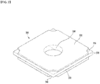
- FIG. 6 is a perspective view of the holder before the liquid lens is seated therein in the camera module according to the embodiment
- FIG. 7 is a longitudinal sectional view taken along line III-III in FIG. 4 , which shows the state in which the liquid lens is seated in the holder shown in FIG. 6
- FIG. 8 is a front view of the support portion shown in FIG. 6
- FIG. 9 is a front view of a support portion according to another embodiment.
- the holder includes the first lens disposition portion 510, in which the first lens unit 100 is disposed, the second lens disposition portion 530, in which the second lens unit 200 is disposed, and the liquid lens disposition portion 520, which is disposed between the first lens disposition portion 510 and the second lens disposition portion 530 to allow the liquid lens 300 to be disposed therein.
- the through-hole is formed so as to penetrate the first lens disposition portion 510, the second lens disposition portion 530, and the liquid lens disposition portion 520.
- the liquid lens disposition portion 520 includes the support portion 524, which protrudes upwards inside the holder 500 so as to enclose the through-hole 501 (refer to FIG. 8 ) in order to allow the liquid lens 300 to be seated thereon.
- the through-hole 501 may have a circular horizontal cross-section, and the support portion 524 may be disposed so as to concentrically surround the through-hole 501.
- the horizontal cross-section of the through-hole 501 may have an oval or polygonal shape, and the support portion 524 may be modified so as to enclose the circumference of the through-hole 501 while corresponding to the horizontal cross-section of the through-hole 501.
- the liquid lens disposition portion 520 may include a first horizontal plate 521, a second horizontal plate 523, and a vertical plate 522.
- the first horizontal plate 521 may be a first body portion
- the second horizontal plate 523 may be a second body portion
- the vertical plate 522 may be a side portion.
- the first horizontal plate may include a first hole formed therein
- the second horizontal plate may include a second hole formed therein.
- the second horizontal plate or the second body portion may include the support portion 524, which protrudes toward the liquid lens to support the liquid lens, and an extension portion 523.
- the first horizontal plate 521 may be disposed in the upper region of the holder 500, and may be coupled to the first lens disposition portion.
- the second horizontal plate 523 may be disposed below the first horizontal plate 521 so as to be spaced apart from the first horizontal plate 521, and may be coupled to the second lens disposition portion 520.
- the vertical plate 522 connects the first horizontal plate 521 and the second horizontal plate 523 to each other in order to form the second region, which is a space in the holder 500 in which the liquid lens 300 is disposed.
- the vertical plate 522 may include a pair of left and right pieces so as to connect opposite edges of the first horizontal plate 521 and opposite edges of the second horizontal plate 523 to each other.
- the support portion 524 may be formed so as to protrude from the second horizontal plate 523 while enclosing the through-hole 501.
- the support portion 524 may be formed such that a stepped surface 524b is formed in the region of the support portion 524 in which the above-described mold seam 523a is formed.
- the support portion may include a side surface and an upper surface, and may further include a step between the side surface and the upper surface.
- the step may be two or more in number.
- at least two steps may be parallel to each other.
- the steps may be disposed at locations corresponding to the side portion of the holder.
- the interval between the steps, which are parallel to each other may be smaller than the diameter of the second hole.
- the height of each step may be 20 to 40 ⁇ m.
- the stepped surface 524b may have a shape that is stepped downwards from the upper surface 524a of the support portion 524.
- the stepped surface 524b may be disposed in a pair at opposite edges of the upper surface 524a of the support portion 524.
- the stepped surface 524b may be formed such that any one region thereof is contiguous with the through-hole 501.
- the stepped surface 524b having the above structure may prevent the liquid lens 300 from being tilted or shaken by the support portion 524 supporting the liquid lens 300.
- the protruding portion protruding from the upper surface of the first body portion may have a linear shape.
- the step may be disposed perpendicular to the protruding portion.
- the protruding portion or the mold seam 523a may be formed so as to be elongated across the center of the through-hole 501.
- the mold seam 523a may protrude from the upper surface of the second horizontal plate 523 of the liquid lens disposition portion 520 so as to cross the center of the through-hole 501, and may also be formed so as to protrude from the upper region of the stepped surface 524b.
- the stepped surface 524b has a lower height than the support portion 524, as shown in FIG. 7 , the third plate 330 of the liquid lens 300 is spaced apart from the stepped surface 524b, and thus is not affected by the mold seam 523a. As a result, the liquid lens 300 may be supported by the support portion 524 in a stable and balanced manner.
- the third plate of the liquid lens 300 is illustrated as being slightly spaced apart from the upper surface 524a of the support portion 524. However, this is exaggerated merely for the purpose of illustration.
- the lower surface of the third plate of the liquid lens 300 is brought into close contact with the upper surface 524a of the support portion 524, with the result that the liquid lens 300 is supported by the support portion 524 in a stable and balanced manner.
- the upper surface 524a of the support portion 524 and the stepped surface 524b may have a difference in height of 20 to 40 ⁇ m therebetween.
- this height difference may be modified without being limited to this specific range, so long as it is greater than the height of the mold seam 523a formed at the support portion 524.
- a pair of stepped surfaces 524b may be formed by cutting opposite edges of the upper surface 524a of the support portion 524 such that the side of each of the stepped surfaces 524b that is contiguous with the through-hole 501 is perpendicular to the mold seam 523a.
- This structure may be directly realized using a mold in the injection molding process, or may be realized through a cutting process or the like for removing the mold seam 523a formed on the upper surface 524a of the support portion 524 after the injection molding process. Accordingly, the mold seam 523a is not substantially formed on the upper surface 524a of the support portion 524, which supports the liquid lens 300.
- a stepped surface 524b-1 may be disposed parallel to the mold seam 523a.
- the stepped surface 524b-1 may be disposed in a pair so as to correspond to each other.
- the width of each of the stepped surfaces 524b-1 may be set to any value within the range within which the liquid lens 300 is supported in a balanced manner by removing the mold seam 523a from the upper surface 524a-1 of the support portion 524.
- the stepped surface 524b-1 may be directly realized using a mold in the injection molding process, or may be realized through a cutting process or the like for removing the mold seam 523a formed on the upper surface 524a-1 of the support portion 524 after the injection molding process.
- the surface of the support portion on which the liquid lens is seated is substantially flattened, thereby enabling more stable support of the liquid lens in the holder.
- the camera module including the above-described liquid lens may be mounted in various digital devices, such as a digital camera, a smartphone, a laptop computer, and a tablet PC.
- the camera module may be mounted in mobile devices to realize an ultra-thin high-performance zoom lens.
- a display device in which the camera module, including the liquid lens, the first and second lens units, the filter, and the light-receiving element, converts an image incident from the outside into an electrical signal, may include a display module including a plurality of pixels, the colors of which are changed by the electrical signal.
- the display module and the camera module may be controlled by a control unit.
- a camera module including a liquid lens according to the embodiment may be used in mobile devices.
Abstract
Description
- Embodiments relate to a camera module, and more particularly to a camera module including a liquid lens.
- People who use portable devices demand optical devices that have high resolution, are small, and have various photographing functions (an autofocus (AF) function, a hand-tremor compensation or optical image stabilization (OIS) function, etc.). Such photographing functions may be realized by directly moving a plurality of lenses that are combined. In the case in which the number of lenses is increased, however, the size of an optical device may be increased.
- The autofocus and hand-tremor compensation functions are performed by tilting or moving a lens module including a plurality of lenses, which are fixed to a lens holder in the state in which the optical axes of the lenses are aligned, along the optical axis or in a direction perpendicular to the optical axis. An additional lens-moving apparatus is used to move the lens module. However, the lens-moving apparatus consumes a lot of power, requires driving members, such as magnets and coils, to move the lens module, and requires extra space corresponding to the moving range of the lens module in order to move the lens module, thus leading to an increase in the overall thickness of a camera module and an optical device.
- Therefore, research has been conducted on a liquid lens configured to electrically adjust the curvature of an interface between two kinds of liquid in order to perform autofocus and hand-tremor compensation functions.
- Embodiments provide a camera module including a liquid lens and an optical device, in which the liquid lens is more stably supported inside a holder.
- Embodiments provide a camera module including a liquid lens and an optical device, in which the liquid lens is supported in a balanced manner even when a mold seam is formed in the process of manufacturing a holder through injection molding.
- In one embodiment, a camera module may include a liquid lens including an electrode, a holder including a through-hole formed therein and a support portion protruding upwards while enclosing the through-hole so as to allow the liquid lens to be seated thereon, and a stepped surface formed in a region of the support portion in which a mold seam is formed so as to be stepped downwards from the upper surface of the support portion.
- The holder may include a first lens disposition portion in which a first lens unit is disposed, a second lens disposition portion in which a second lens unit is disposed, and a liquid lens disposition portion disposed between the first lens disposition portion and the second lens disposition portion to allow the liquid lens to be disposed therein. The through-hole may penetrate the first lens disposition portion, the second lens disposition portion, and the liquid lens disposition portion.
- The liquid lens disposition portion may include a first horizontal plate coupled to the first lens disposition portion, a second horizontal plate spaced apart from the first horizontal plate and coupled to the second lens disposition portion, and a vertical plate connecting the first horizontal plate and the second horizontal plate to each other. The support portion may protrude from the second horizontal plate while enclosing the through-hole.
- The through-hole may have a circular horizontal cross-section, and the support portion may be disposed so as to concentrically surround the through-hole.
- The difference in height between the upper surface of the support portion and the stepped surface may be 20 to 40 µm.
- Any one region of the stepped surface may be contiguous with the through-hole.
- The mold seam may be formed so as to be elongated across the center of the through-hole, and the stepped surface may be disposed in a pair at opposite edges of the upper surface of the support portion.
- The pair of stepped surfaces may be formed by cutting opposite edges of the upper surface of the support portion such that the side of each of the stepped surfaces that is contiguous with the through-hole is perpendicular to the mold seam.
- The stepped surfaces may be disposed parallel to the mold seam.
- The liquid lens may include a first plate including a cavity formed therein to accommodate a first liquid, which is conductive, and a second liquid, which is non-conductive, therein, a first electrode disposed on the first plate, a second electrode disposed under the first plate, a second plate disposed on the first electrode, and a third plate disposed under the second electrode and seated on the support portion.
- The stepped surfaces may be spaced apart from the third plate.
- In another embodiment, an optical device may include a camera module, which includes a liquid lens including an electrode, a holder including a through-hole formed therein and a support portion protruding upwards while enclosing the through-hole to allow the liquid lens to be seated thereon, and a stepped surface formed in a region of the support portion in which a mold seam is formed so as to be stepped downwards from the upper surface of the support portion on which a seam is not formed, a control unit converting an image incident through the camera module into an electrical signal, and a display module including a plurality of pixels, the colors of which are changed by the electrical signal.
- In the camera module including the liquid lens and the optical device according to the embodiments, the surface of the support portion on which the liquid lens is seated is substantially flattened, thereby enabling more stable support of the liquid lens in the holder.
- In addition, even when a mold seam is formed in the process of manufacturing the holder through injection molding, it is possible to support the liquid lens in a balanced manner by forming a stepped portion on the support portion.
-
-
FIG. 1 is a view of one example of a camera module, -
FIG. 2 is a perspective view of a liquid lens included in the camera module shown inFIG. 1 , -
FIG. 3 is a view showing the cross-section of the liquid lens shown inFIG. 2 , -
FIG. 4 is a perspective view showing the liquid lens and the holder of the camera module shown inFIG. 1 , -
FIG. 5 is a longitudinal sectional view taken along line II-II inFIG. 4 , -
FIG. 6 is a perspective view of the holder before the liquid lens is seated therein in the camera module according to the embodiment, -
FIG. 7 is a longitudinal sectional view taken along line III-III inFIG. 4 , which shows the state in which the liquid lens is seated in the holder shown inFIG. 6 , -
FIG. 8 is a front view of the support portion shown inFIG. 6 , and -
FIG. 9 is a front view of a support portion according to another embodiment. - Hereinafter, embodiments for accomplishing the aforementioned objects will be described with reference to the accompanying drawings.
- In the following description of the embodiments, it will be understood that, when each element is referred to as being "on" or "under" another element, it can be "directly" on or under another element or can be "indirectly" formed such that an intervening element is also present. In addition, when an element is referred to as being "on" or "under", "under the element" as well as "on the element" may be included based on the element.
-
FIG. 1 is a view of one example of a camera module. The camera module may include alens assembly 100 and acontrol circuit 2000. - The
lens assembly 1000 may include a liquid lens and/or a solid lens. The liquid lens may include a liquid, a plate, and an electrode. The liquid may include a conductive liquid and a non-conductive liquid, and the electrode may be disposed on or under the plate. In addition, the electrode may include a common terminal and an individual terminal. The common terminal may be single in number, and the individual terminal may be plural in number. The plate may include a first plate, which includes a cavity in which the liquid is disposed, and may further include a second plate, which is disposed on or under the first plate. In addition, the liquid lens may further include a third plate, and the first plate may be disposed between the second plate and the third plate. The shape of the interface formed between the conductive liquid and the non-conductive liquid may be changed in response to the driving voltage applied between the common terminal and each of the individual terminals, and accordingly the focal length may be changed. Thecontrol circuit 2000 may supply a driving voltage to the liquid lens, and may be disposed on asensor board 800 on which an image sensor is disposed. The camera module may further include aconnector 3000. Theconnector 3000 may be connected to thecontrol circuit 2000 via aconnection part 3500, and may electrically connect thecontrol circuit 2000 to an external power source or other devices. - The configuration of the
control circuit 2000 may be designed differently in accordance with the specifications required for a photography device. In particular, in order to reduce the intensity of the operating voltage to be applied to thelens assembly 1000, thecontrol circuit 2000 may be implemented as a single chip. As a result, it is possible to further reduce the size of the camera module that is mounted in a portable device. - The
lens assembly 1000 may include afirst lens unit 100, asecond lens unit 400, aliquid lens 300, aholder 500, and acover 600. Any one of thefirst lens unit 100 and thesecond lens unit 400 may be omitted. - The illustrated structure of the
lens assembly 1000 is just one example, and the structure of thelens assembly 1000 may be changed depending on the specifications required for the camera module. - The
first lens unit 100 may be disposed at the front side of thelens assembly 1000, and may receive light incident thereon from the outside of thelens assembly 1000. Thefirst lens unit 100 may include at least one lens, or two or more lenses may be aligned along a center axis to form an optical system. Here, the center axis may be the same as the optical axis of the optical system. - The
first lens unit 100 may include two lenses. However, the disclosure is not limited thereto. - An exposure lens (not shown) may be provided on the front surface of the
first lens unit 100, and a cover glass may be disposed in front of the exposure lens. The exposure lens may protrude so as to be exposed to the outside of theholder 500, and thus the surface thereof may be damaged. If the surface of the lens is damaged, the quality of the image captured by the camera module may be deteriorated. In order to prevent or minimize damage to the surface of the exposure lens, a method of disposing a cover glass, a method of forming a coating layer, or a method of forming the exposure lens using a wear-resistant material for preventing damage to the surface of the exposure lens may be applied. - The
second lens unit 400 may be disposed at the rear of thefirst lens unit 100 and theliquid lens 300, and the light incident on thefirst lens unit 100 from the outside may pass through theliquid lens 300 and may be incident on thesecond lens unit 400. Thesecond lens unit 400 may be spaced apart from thefirst lens unit 100 and may be disposed in a through-hole formed in theholder 500. Thesecond lens unit 400 may include at least one lens, and when two or more lenses are included, the lenses may be aligned along the center axis to form an optical system. - In order to distinguish the above-described first and
second lens units liquid lens 300, the first andsecond lens units - The
liquid lens 300 may be disposed under thefirst lens unit 100, and thesecond lens unit 400 may be disposed under theliquid lens 300. That is, theliquid lens 300 may be disposed between thefirst lens unit 100 and thesecond lens unit 400. -
FIG. 2 is a perspective view of the liquid lens included in the camera module shown inFIG. 1 , andFIG. 3 is a view showing the cross-section of the liquid lens shown inFIG. 2 . - Specifically, the
liquid lens 300 may include afirst plate 310, in which a cavity is formed to accommodate afirst liquid 350, which is non-conductive, and asecond liquid 340, which is conductive, therein, a first electrode 355 disposed on thefirst plate 310, asecond electrode 345 disposed under the first plate, asecond plate 320 disposed on the first electrode 355, and athird plate 330 disposed under thesecond electrode 345. - The
first plate 310 may be disposed between thesecond plate 320 and thethird plate 330, and may include upper and lower openings having a predetermined inclined surface (e.g. an inclined surface having an angle of about 50 to 70 degrees, specifically an angle of 55 to 65 degrees). The region surrounded by the aforementioned inclined surface, the opening contacting thesecond plate 320, and the opening contacting thethird plate 330 may be referred to as a 'cavity'. - The
first plate 310 is a structure that accommodates the first andsecond liquids second plate 320 and thethird plate 330 may include a region through which light passes, and thus may be made of a light-transmissive material such as, for example, glass. Thesecond plate 320 and thethird plate 330 may be made of the same material for convenience of processing. - In addition, the
first plate 310 may include impurities so that light does not easily pass therethrough. - The
second plate 320 is a structure through which light incident thereon from thefirst lens unit 100 travels to the interior of the cavity, and thethird plate 330 is a structure through which the light that has passed through the cavity travels to thesecond lens unit 400. - The aforementioned cavity may be filled with the
first liquid 350 and thesecond liquid 340, which have different properties from each other, and an interface may be formed between thefirst liquid 350 and thesecond liquid 340. The curvature and the inclination of the interface formed between thefirst liquid 350 and thesecond liquid 340 may be changed. - That is, a configuration in which the surface tension of the first and
second liquids - The
first liquid 350 may be oil, e.g. phenyl-based silicon oil. - The
second liquid 340 may be made of, for example, a mixture of ethylene glycol and sodium bromide (NaBr). - Each of the
first liquid 350 and thesecond liquid 340 may include at least one of a sterilizing agent or an antioxidant. The sterilizing agent may be a phenol-based antioxidant or a phosphorus (P)-based antioxidant. The sterilizing agent may be any one of an alcohol-based sterilizing agent, an aldehyde-based sterilizing agent, and a phenol-based sterilizing agent. - The first electrode 355 may be spaced apart from the
second electrode 345, and may be disposed on the upper surface, the side surface, and a portion of the lower surface of thefirst plate 310. Thesecond electrode 345 may be disposed on a portion of the lower surface of thefirst plate 310, and may be in direct contact with thesecond liquid 340. - The side surface of the
first plate 310 or the side surface of aninsulation layer 360 may form the inclined surface or the side wall of the cavity. The first electrode 355 may be in contact with the first andsecond liquids insulation layer 360 interposed therebetween, which will be described later. Thesecond electrode 345 may be in direct contact with thesecond liquid 340. - An electrical signal received from an
external sensor board 800 may be applied to the first electrode 355 and thesecond electrode 345 in order to control the interface between thefirst liquid 350 and thesecond liquid 340. - The first electrode 355 and the
second electrode 345 may be made of a conductive material, e.g. metal, and specifically may include chrome (Cr). Chromium or chrome is a glossy silver rigid transition metal, which is not fragile, does not readily discolor, and has a high melting point. - Further, since an alloy including chromium exhibits high corrosion resistance and rigidity, chromium may be used in the state of being alloyed with other metals. In particular, since chrome (Cr) is not easily corroded or discolored, chrome exhibits high resistance to the conductive liquid in the cavity.
- The
insulation layer 360 may be disposed so as to cover the lower surface of thesecond plate 330 on the upper surface of the cavity, the first electrode 355 forming the side wall of the cavity, a portion of the first electrode 355 on the lower surface of thefirst plate 310, thefirst plate 310, and thesecond electrode 345. Theinsulation layer 360 may be implemented as, for example, a parylene C coating agent, and may further include a white dye. The white dye may increase the degree to which light is reflected by theinsulation layer 360 forming the side wall i of the cavity. - As illustrated, the
first liquid 350 may be in surface contact with thesecond plate 320, with theinsulation layer 360 interposed therebetween, and thesecond liquid 340 may be in direct surface contact with thethird plate 330. - The cavity may include a first opening that is oriented toward the
second plate 320 and a second opening that is oriented toward thethird plate 330. The cross-sectional size O1 of the first opening may be smaller than the cross-sectional size O2 of the second opening, or vice versa. Here, when each of the first and second openings has a circular cross-section, the size of the openings may refer to a radius thereof, and when each of the openings has a square cross-section, the size of the openings may refer to a diagonal length thereof. - Each of the
second plate 320 and thethird plate 330 may have rectangular edges. However, the disclosure is not limited thereto. - The first electrode 355 may be exposed from at least one region of the edges of the
second plate 320, and thesecond electrode 345 may be exposed from at least one region of the edges of thethird plate 330. - In addition, a
first connection electrode 356 may be disposed on the first electrode 355 in the outer region of thesecond plate 320, and asecond connection electrode 346 may be disposed on thesecond electrode 345 in the outer region of thethird plate 300. - Although not illustrated, a conductive epoxy may be disposed between the first electrode 355 and the
first connection electrode 356, and may also be disposed between thesecond electrode 345 and thesecond connection electrode 346. - The
first connection electrode 356 may be integrally formed with the first electrode 355, and thesecond connection electrode 346 may be integrally formed with thesecond electrode 345. - The
first connection electrode 356 and thesecond connection electrode 346 may be connected to a metal plate 390 via aconnection board 380, and may be electrically connected toterminals 810 of aflexible sensor board 800. - As shown in
FIG. 1 , theholder 500 may include an open upper portion, an open lower portion, and a through-hole formed therein. Theholder 500 may include a first body portion including a first hole formed therein, a second body portion including a second hole formed therein, and a side portion connecting the first body portion and the second body portion to each other. The side surface of the holder may include at least one side hole formed therein. The side surface of the holder may include a first side hole and a second side hole formed therein. The first side hole and the second side hole may be disposed opposite each other while being spaced apart from each other. The first lens unit 200, thesecond lens unit 400, and theliquid lens 300 may be disposed in the through-hole formed in theholder 500. In detail, thefirst lens unit 100 may be disposed in the upper portion of theholder 500 and may be coupled thereto, and thesecond lens unit 400 may be disposed in the lower portion of theholder 500 and may be coupled thereto. - The
liquid lens 300, thefirst lens unit 100 disposed on the liquid lens, and thesecond lens unit 400 disposed under the liquid lens may be disposed in theholder 500 so as to be fixed thereto. Theliquid lens 300 may be aligned along the center axis in the same manner as thefirst lens unit 100 and thesecond lens unit 400. The first lens unit may be disposed in the first hole, and the second lens unit may be disposed in the second hole. - First to third regions may be provided inside the
holder 500. Thefirst lens unit 100 may be inserted into the first region, theliquid lens 300 may be disposed in the second region, and thesecond lens unit 400 may be disposed in the third region. Here, the first region may be located on the second region, and the third region may be located under the second region. The aforementioned through-hole formed in theholder 500 may include the first to third regions. - The second region may include an opening, which is formed in the side surface of the
holder 500 so as to allow theliquid lens 300 to be inserted into the holder therethrough. Thus, theliquid lens 300 may be inserted into theholder 500 through the side opening formed in theholder 500, and may be accommodated in the second region of theholder 500. - The
liquid lens 300 accommodated in theholder 500 may be electrically connected to theterminals 810 of thesensor board 800 using theconnection board 380, which is exposed to the outside of theholder 500. Here, theconnection board 380 may be, for example, a flexible printed circuit board. - The
connection board 380 may include an upper terminal unit including a plurality of terminals and a lower terminal unit including a plurality of terminals. The upper terminal unit may be coupled to the first andsecond connection electrodes liquid lens 300, and thus may be connected to the first electrode 355 or thesecond electrode 345. Although it is illustrated inFIG. 3 that the upper terminal unit of theconnection board 380 is connected to thesecond electrode 345 of theliquid lens 300, the upper terminal unit of theconnection board 380 may be connected to the first electrode 355. Alternatively, the upper terminal unit of theconnection board 380 may be integrated with the first andsecond connection electrodes second electrode 345 of theliquid lens 300. - The
cover 600 may be disposed so as to surround thefirst lens 100, thesecond lens 400, theliquid lens 300, and theholder 500. Thecover 600 and theholder 500 may be disposed on abase 700. - The base 700 may be integrally formed with the
holder 500. Theholder 500 may act as the base 700 as needed. At this time, thebase 700 may be omitted. - The
sensor board 800 may be disposed under thebase 700, and may include an image sensor (not shown) andterminals 810. A light-receiving element of the image sensor may be provided in thesensor board 800. The width and/or the length of a unit pixel of the image sensor may be, for example, 2 µm (micrometers) or less. Theterminals 810 may supply current to the first and second electrodes 355 and 345 (refer toFIG. 2 ) of theliquid lens 300 using theconnection board 380. -
FIG. 4 is a perspective view showing the liquid lens and the holder of the camera module shown inFIG. 1 , andFIG. 5 is a longitudinal sectional view taken along line II-II inFIG. 4 . - As shown in
FIG. 4 , the above-describedholder 500 may be formed through injection molding, and may include a firstlens disposition portion 510, which includes the first region in which thefirst lens unit 100 is disposed, a liquidlens disposition portion 520, which includes the side opening through which theliquid lens 300 is inserted and the second region in which theliquid lens 300 is disposed, and a secondlens disposition portion 530, which includes the third region in which thesecond lens unit 400 is disposed. - Injection molding is a method of obtaining products by forcibly injecting plastic materials, such as plastic, melted by heat into an injection mold, and then solidifying the same. In general, an injection mold includes an upper mold (or a first mold) and a lower mold (or a second mold), which are separated from each other. When injection molding is performed, an injection process is performed after the upper mold and the lower mold are joined to each other.
- After the product is solidified in the injection mold, the upper mold and the lower mold are separated from each other. During the manufacturing process using injection molding, molten material may minutely flow into the join portion between the molds. Therefore, when the molds are separated from each other, a fine linear protruding portion or depressed portion (hereinafter referred to as a "mold seam") may be formed in the surface of the product.
- Referring to
FIG. 5 showing the longitudinal section taken along line II-II inFIG. 4 , it can be seen that theliquid lens 300 is placed on asupport portion 524 when theliquid lens 300 is disposed in the liquidlens disposition portion 520. - As shown in an enlarged manner in
FIG. 5 , since theholder 500 is manufactured through injection molding, a protruding portion due to theaforementioned mold seam 523a may be formed at thesupport portion 524. The protruding portion may be located on the upper surface of thesupport portion 524, and may have a linear shape. Themold seam 523a may be brought into contact with thethird plate 330 of theliquid lens 300, and thus theliquid lens 300 may not be balanced but may be tilted or move unstably, which may adversely affect the performance of the camera module. - Therefore, the structure of the
holder 500 that is capable of more stably supporting theliquid lens 300 in theholder 500 will be described with reference toFIGS. 6 to 9 . -
FIG. 6 is a perspective view of the holder before the liquid lens is seated therein in the camera module according to the embodiment,FIG. 7 is a longitudinal sectional view taken along line III-III inFIG. 4 , which shows the state in which the liquid lens is seated in the holder shown inFIG. 6 ,FIG. 8 is a front view of the support portion shown inFIG. 6 , andFIG. 9 is a front view of a support portion according to another embodiment. - As shown in
FIG. 6 , the holder includes the firstlens disposition portion 510, in which thefirst lens unit 100 is disposed, the secondlens disposition portion 530, in which the second lens unit 200 is disposed, and the liquidlens disposition portion 520, which is disposed between the firstlens disposition portion 510 and the secondlens disposition portion 530 to allow theliquid lens 300 to be disposed therein. Here, the through-hole is formed so as to penetrate the firstlens disposition portion 510, the secondlens disposition portion 530, and the liquidlens disposition portion 520. - Here, the liquid
lens disposition portion 520 includes thesupport portion 524, which protrudes upwards inside theholder 500 so as to enclose the through-hole 501 (refer toFIG. 8 ) in order to allow theliquid lens 300 to be seated thereon. - For example, the through-
hole 501 may have a circular horizontal cross-section, and thesupport portion 524 may be disposed so as to concentrically surround the through-hole 501. In some embodiments, the horizontal cross-section of the through-hole 501 may have an oval or polygonal shape, and thesupport portion 524 may be modified so as to enclose the circumference of the through-hole 501 while corresponding to the horizontal cross-section of the through-hole 501. - In more detail, the liquid
lens disposition portion 520 may include a firsthorizontal plate 521, a secondhorizontal plate 523, and avertical plate 522. The firsthorizontal plate 521 may be a first body portion, the secondhorizontal plate 523 may be a second body portion, and thevertical plate 522 may be a side portion. The first horizontal plate may include a first hole formed therein, and the second horizontal plate may include a second hole formed therein. The second horizontal plate or the second body portion may include thesupport portion 524, which protrudes toward the liquid lens to support the liquid lens, and anextension portion 523. - The first
horizontal plate 521 may be disposed in the upper region of theholder 500, and may be coupled to the first lens disposition portion. The secondhorizontal plate 523 may be disposed below the firsthorizontal plate 521 so as to be spaced apart from the firsthorizontal plate 521, and may be coupled to the secondlens disposition portion 520. Thevertical plate 522 connects the firsthorizontal plate 521 and the secondhorizontal plate 523 to each other in order to form the second region, which is a space in theholder 500 in which theliquid lens 300 is disposed. Thevertical plate 522 may include a pair of left and right pieces so as to connect opposite edges of the firsthorizontal plate 521 and opposite edges of the secondhorizontal plate 523 to each other. - The
support portion 524 may be formed so as to protrude from the secondhorizontal plate 523 while enclosing the through-hole 501. Thesupport portion 524 may be formed such that a steppedsurface 524b is formed in the region of thesupport portion 524 in which the above-describedmold seam 523a is formed. The support portion may include a side surface and an upper surface, and may further include a step between the side surface and the upper surface. The step may be two or more in number. Among the plurality of steps, at least two steps may be parallel to each other. The steps may be disposed at locations corresponding to the side portion of the holder. The interval between the steps, which are parallel to each other, may be smaller than the diameter of the second hole. The height of each step may be 20 to 40 µm. - The stepped
surface 524b may have a shape that is stepped downwards from theupper surface 524a of thesupport portion 524. The steppedsurface 524b may be disposed in a pair at opposite edges of theupper surface 524a of thesupport portion 524. - In this case, the stepped
surface 524b may be formed such that any one region thereof is contiguous with the through-hole 501. - Even when the
mold seam 523a, which is a protruding portion protruding from the upper surface of the first body portion, is formed in the process of manufacturing theholder 500 through injection molding, the steppedsurface 524b having the above structure may prevent theliquid lens 300 from being tilted or shaken by thesupport portion 524 supporting theliquid lens 300. The protruding portion protruding from the upper surface of the first body portion may have a linear shape. The step may be disposed perpendicular to the protruding portion. - The protruding portion or the
mold seam 523a may be formed so as to be elongated across the center of the through-hole 501. For example, themold seam 523a may protrude from the upper surface of the secondhorizontal plate 523 of the liquidlens disposition portion 520 so as to cross the center of the through-hole 501, and may also be formed so as to protrude from the upper region of the steppedsurface 524b. - However, since the stepped
surface 524b has a lower height than thesupport portion 524, as shown inFIG. 7 , thethird plate 330 of theliquid lens 300 is spaced apart from the steppedsurface 524b, and thus is not affected by themold seam 523a. As a result, theliquid lens 300 may be supported by thesupport portion 524 in a stable and balanced manner. - In
FIG. 7 , the third plate of theliquid lens 300 is illustrated as being slightly spaced apart from theupper surface 524a of thesupport portion 524. However, this is exaggerated merely for the purpose of illustration. The lower surface of the third plate of theliquid lens 300 is brought into close contact with theupper surface 524a of thesupport portion 524, with the result that theliquid lens 300 is supported by thesupport portion 524 in a stable and balanced manner. - In order to achieve the above effects, the
upper surface 524a of thesupport portion 524 and the steppedsurface 524b may have a difference in height of 20 to 40 µm therebetween. However, this height difference may be modified without being limited to this specific range, so long as it is greater than the height of themold seam 523a formed at thesupport portion 524. - As shown in
FIG. 8 , a pair of steppedsurfaces 524b may be formed by cutting opposite edges of theupper surface 524a of thesupport portion 524 such that the side of each of the stepped surfaces 524b that is contiguous with the through-hole 501 is perpendicular to themold seam 523a. This structure may be directly realized using a mold in the injection molding process, or may be realized through a cutting process or the like for removing themold seam 523a formed on theupper surface 524a of thesupport portion 524 after the injection molding process. Accordingly, themold seam 523a is not substantially formed on theupper surface 524a of thesupport portion 524, which supports theliquid lens 300. - In another embodiment, as shown in
FIG. 9 , a steppedsurface 524b-1 may be disposed parallel to themold seam 523a. In this case as well, the steppedsurface 524b-1 may be disposed in a pair so as to correspond to each other. The width of each of the stepped surfaces 524b-1 may be set to any value within the range within which theliquid lens 300 is supported in a balanced manner by removing themold seam 523a from theupper surface 524a-1 of thesupport portion 524. - In this embodiment, the stepped
surface 524b-1 may be directly realized using a mold in the injection molding process, or may be realized through a cutting process or the like for removing themold seam 523a formed on theupper surface 524a-1 of thesupport portion 524 after the injection molding process. - In the camera module including the liquid lens and the optical device according to the embodiments, the surface of the support portion on which the liquid lens is seated is substantially flattened, thereby enabling more stable support of the liquid lens in the holder.
- In addition, even when a mold seam is formed in the process of manufacturing the holder through injection molding, it is possible to support the liquid lens in a balanced manner by forming a stepped portion on the support portion.
- The camera module including the above-described liquid lens may be mounted in various digital devices, such as a digital camera, a smartphone, a laptop computer, and a tablet PC. In particular, the camera module may be mounted in mobile devices to realize an ultra-thin high-performance zoom lens.
- For example, a display device, in which the camera module, including the liquid lens, the first and second lens units, the filter, and the light-receiving element, converts an image incident from the outside into an electrical signal, may include a display module including a plurality of pixels, the colors of which are changed by the electrical signal. The display module and the camera module may be controlled by a control unit.
- While the present disclosure has been particularly shown and described with reference to exemplary embodiments thereof, these embodiments are only proposed for illustrative purposes and do not restrict the present disclosure, and it will be apparent to those skilled in the art that various changes in form and detail may be made without departing from the essential characteristics of the embodiments set forth herein. For example, respective configurations set forth in the embodiments may be modified and applied. Further, differences in such modifications and applications should be construed as falling within the scope of the present disclosure as defined by the appended claims.
- A camera module including a liquid lens according to the embodiment may be used in mobile devices.
Claims (10)
- A camera module, comprising:a liquid lens comprising an electrode; anda holder in which the liquid lens is disposed,wherein the holder comprises:a first body portion comprising a first hole formed therein;a second body portion spaced apart from the first body portion, the second body portion comprising a second hole formed therein so as to correspond to the first hole; anda side portion connecting the first body portion and the second body portion to each other,wherein the second body portion comprises a support portion supporting the liquid lens and an extension portion extending from the support portion, andwherein the support portion comprises a side surface, an upper surface, and a step formed between the side surface and the upper surface.
- The camera module according to claim 1, wherein a first lens unit comprising at least one lens is disposed in the first hole,
wherein a second lens unit comprising at least one lens is disposed in the second hole,
wherein the liquid lens is disposed between the first lens unit and the second lens unit, and
wherein the support portion protrudes from the extension portion toward the liquid lens. - The camera module according to claim 1, wherein the second hole has a circular horizontal cross-section, and
wherein at least a portion of a stepped surface of the step is contiguous with the second hole. - The camera module according to claim 1, wherein the step is disposed so as to correspond to the side portion.
- The camera module according to claim 1, wherein the step is two or more in number.
- The camera module according to claim 1, wherein the step has a height of 20 to 40 µm.
- The camera module according to claim 1, wherein the first body portion comprises a protruding portion protruding upwards from an upper surface thereof in a linear shape.
- The camera module according to claim 7, wherein the step is disposed such that one side thereof that is contiguous with the second hole is perpendicular to the protruding portion.
- The camera module according to claim 1, wherein the liquid lens comprises:a first plate comprising a cavity formed therein to accommodate a first liquid, which is conductive, and a second liquid, which is non-conductive;a first electrode disposed on the first plate;a second electrode disposed under the first plate;a second plate disposed on the first electrode; anda third plate disposed under the second electrode and seated on the support portion.
- The camera module according to claim 9, wherein the step is spaced apart from the third plate.
Applications Claiming Priority (2)
| Application Number | Priority Date | Filing Date | Title |
|---|---|---|---|
| KR1020170029519A KR102402614B1 (en) | 2017-03-08 | 2017-03-08 | Camera module including liquid lens, optical device including the same |
| PCT/KR2018/002744 WO2018164496A1 (en) | 2017-03-08 | 2018-03-08 | Camera module comprising liquid lens |
Publications (2)
| Publication Number | Publication Date |
|---|---|
| EP3594727A1 true EP3594727A1 (en) | 2020-01-15 |
| EP3594727A4 EP3594727A4 (en) | 2020-12-30 |
Family
ID=63448776
Family Applications (1)
| Application Number | Title | Priority Date | Filing Date |
|---|---|---|---|
| EP18763567.7A Pending EP3594727A4 (en) | 2017-03-08 | 2018-03-08 | Camera module comprising liquid lens |
Country Status (6)
| Country | Link |
|---|---|
| US (1) | US11204451B2 (en) |
| EP (1) | EP3594727A4 (en) |
| JP (1) | JP7086979B2 (en) |
| KR (1) | KR102402614B1 (en) |
| CN (2) | CN110418985B (en) |
| WO (1) | WO2018164496A1 (en) |
Families Citing this family (1)
| Publication number | Priority date | Publication date | Assignee | Title |
|---|---|---|---|---|
| US10620380B1 (en) * | 2018-11-02 | 2020-04-14 | Nanning Fugui Precision Industrial Co., Ltd. | Camera module with non-mechanical light-blocking and light-passing function and electronic device using the camera module |
Family Cites Families (29)
| Publication number | Priority date | Publication date | Assignee | Title |
|---|---|---|---|---|
| JP4004705B2 (en) * | 2000-02-29 | 2007-11-07 | 松下電器産業株式会社 | Imaging device and imaging device assembling method |
| GB0406337D0 (en) * | 2004-01-07 | 2004-04-21 | Koninkl Philips Electronics Nv | Zoom optical system |
| JP4707176B2 (en) * | 2005-04-28 | 2011-06-22 | シチズンホールディングス株式会社 | Imaging lens and camera module |
| JP2007171329A (en) * | 2005-12-20 | 2007-07-05 | Nikon Corp | Lens barrel |
| JP2007292845A (en) * | 2006-04-21 | 2007-11-08 | Citizen Holdings Co Ltd | Camera module |
| JP2007310224A (en) * | 2006-05-19 | 2007-11-29 | Nikon Corp | Lens barrel and camera |
| KR100815328B1 (en) | 2006-08-10 | 2008-03-19 | 삼성전기주식회사 | Liquid-lens assembly |
| KR100847803B1 (en) | 2007-01-04 | 2008-08-06 | (주) 비앤피 사이언스 | Liquid lens and a method for producing the same |
| KR100843473B1 (en) * | 2007-04-26 | 2008-07-03 | 삼성전기주식회사 | An auto-focusing camera module having a liquid lens |
| DE602007013722D1 (en) * | 2007-05-14 | 2011-05-19 | Varioptic Sa | Housing for variable lens |
| JP2009017480A (en) * | 2007-07-09 | 2009-01-22 | Nippon Hoso Kyokai <Nhk> | Camera calibration device and program thereof |
| FR2919074B1 (en) * | 2007-07-19 | 2010-10-22 | Commissariat Energie Atomique | OPTICAL DEVICE WITH MEMBRANE DEFORMABLE BY ELECTROSTATIC ACTUATION |
| EP2085796A1 (en) * | 2008-01-29 | 2009-08-05 | Varioptic | Optical lens arrangement for fixed lenses and a liquid lens |
| JP2009244393A (en) | 2008-03-28 | 2009-10-22 | Fujinon Corp | Lens assembling method and imaging device |
| CN201477276U (en) * | 2009-07-20 | 2010-05-19 | 菱光科技股份有限公司 | Photographic module |
| CN101718385A (en) * | 2009-12-15 | 2010-06-02 | 山东神戎电子股份有限公司 | Split type intelligent following-up cradle head |
| TWI490584B (en) | 2010-11-15 | 2015-07-01 | Hon Hai Prec Ind Co Ltd | Lens module, camera module and method for making lens module |
| JP5802401B2 (en) * | 2011-02-22 | 2015-10-28 | オリンパス株式会社 | Lens frame and lens assembly |
| TW201300911A (en) * | 2011-06-29 | 2013-01-01 | Hon Hai Prec Ind Co Ltd | Three-dimensional image capturing device |
| KR102141690B1 (en) * | 2012-12-06 | 2020-08-05 | 엘지이노텍 주식회사 | Camera Module |
| CN103885153A (en) | 2012-12-20 | 2014-06-25 | 鸿富锦精密工业(深圳)有限公司 | Lens module |
| CN105934696B (en) | 2014-01-25 | 2018-12-04 | 柯尼卡美能达株式会社 | Lens subassembly and photographic device |
| JP6448329B2 (en) * | 2014-11-28 | 2019-01-09 | キヤノン株式会社 | Lens barrel, electronic device, and lens holding member |
| KR20160081243A (en) * | 2014-12-31 | 2016-07-08 | 삼성전기주식회사 | Camera Module |
| CN104574425B (en) * | 2015-02-03 | 2016-05-11 | 中国人民解放军国防科学技术大学 | A kind of demarcation of the master-slave camera chain based on rotating model and interlock method |
| CN104670512B (en) * | 2015-02-13 | 2017-06-20 | 广州市红鹏直升机遥感科技有限公司 | A kind of many camera lens holder for aerial photographing |
| DE102017203304A1 (en) * | 2016-03-17 | 2017-09-21 | Sony Corporation | LENS WASH, OPTICAL SYSTEM, ELECTRONIC EQUIPMENT AND METHOD |
| CN110291013B (en) * | 2018-11-30 | 2021-12-17 | 深圳市大疆创新科技有限公司 | Control method of cradle head, cradle head and unmanned aerial vehicle |
| US20200389593A1 (en) * | 2017-04-10 | 2020-12-10 | SZ DJI Technology Co., Ltd. | Gimbal servo control method and control device |
-
2017
- 2017-03-08 KR KR1020170029519A patent/KR102402614B1/en active IP Right Grant
-
2018
- 2018-03-08 EP EP18763567.7A patent/EP3594727A4/en active Pending
- 2018-03-08 JP JP2019548910A patent/JP7086979B2/en active Active
- 2018-03-08 WO PCT/KR2018/002744 patent/WO2018164496A1/en unknown
- 2018-03-08 US US16/492,065 patent/US11204451B2/en active Active
- 2018-03-08 CN CN201880017025.9A patent/CN110418985B/en active Active
- 2018-11-30 CN CN202111435818.2A patent/CN113942656A/en active Pending
Also Published As
| Publication number | Publication date |
|---|---|
| JP7086979B2 (en) | 2022-06-20 |
| CN110418985A (en) | 2019-11-05 |
| CN113942656A (en) | 2022-01-18 |
| EP3594727A4 (en) | 2020-12-30 |
| US20210132264A1 (en) | 2021-05-06 |
| US11204451B2 (en) | 2021-12-21 |
| KR102402614B1 (en) | 2022-05-27 |
| WO2018164496A1 (en) | 2018-09-13 |
| CN110418985B (en) | 2021-07-20 |
| KR20180102852A (en) | 2018-09-18 |
| JP2020510876A (en) | 2020-04-09 |
Similar Documents
| Publication | Publication Date | Title |
|---|---|---|
| US11543567B2 (en) | Camera module including liquid lens, optical device including the same, and method of manufacturing camera module including liquid lens | |
| US11281075B2 (en) | Camera module including liquid lens | |
| KR101805128B1 (en) | Camera module including liquid lens, optical device including the same and method for manufacturing the camera module | |
| US11526064B2 (en) | Liquid lens and camera module including the same | |
| EP3581988B1 (en) | Camera module including liquid lens, and optical device | |
| EP3575856B1 (en) | Liquid lens module and camera module comprising same | |
| KR20180088235A (en) | Camera module including liquid lens and optical device including the same | |
| US11204451B2 (en) | Camera module comprising liquid lens and optical device including the same | |
| KR102344463B1 (en) | Camera module including liquid lens | |
| KR102645837B1 (en) | Lens assembly and camera module including the same | |
| KR20180088080A (en) | Liquid lens module, camera module and optical device including the same and method for manufacturing the same | |
| KR102362730B1 (en) | Mobile terminal including liquid lens | |
| KR20100108764A (en) | Camera module |
Legal Events
| Date | Code | Title | Description |
|---|---|---|---|
| STAA | Information on the status of an ep patent application or granted ep patent |
Free format text: STATUS: THE INTERNATIONAL PUBLICATION HAS BEEN MADE |
|
| PUAI | Public reference made under article 153(3) epc to a published international application that has entered the european phase |
Free format text: ORIGINAL CODE: 0009012 |
|
| STAA | Information on the status of an ep patent application or granted ep patent |
Free format text: STATUS: REQUEST FOR EXAMINATION WAS MADE |
|
| 17P | Request for examination filed |
Effective date: 20191004 |
|
| AK | Designated contracting states |
Kind code of ref document: A1 Designated state(s): AL AT BE BG CH CY CZ DE DK EE ES FI FR GB GR HR HU IE IS IT LI LT LU LV MC MK MT NL NO PL PT RO RS SE SI SK SM TR |
|
| AX | Request for extension of the european patent |
Extension state: BA ME |
|
| DAV | Request for validation of the european patent (deleted) | ||
| DAX | Request for extension of the european patent (deleted) | ||
| A4 | Supplementary search report drawn up and despatched |
Effective date: 20201126 |
|
| RIC1 | Information provided on ipc code assigned before grant |
Ipc: G02B 27/64 20060101ALI20201120BHEP Ipc: G02B 7/02 20060101ALI20201120BHEP Ipc: G02B 3/14 20060101AFI20201120BHEP Ipc: G02B 26/00 20060101ALI20201120BHEP Ipc: H04N 5/225 20060101ALI20201120BHEP |
|
| STAA | Information on the status of an ep patent application or granted ep patent |
Free format text: STATUS: EXAMINATION IS IN PROGRESS |
|
| 17Q | First examination report despatched |
Effective date: 20230201 |