EP3594703A1 - Wire harness conduction inspection method and wire harness conduction inspection program - Google Patents
Wire harness conduction inspection method and wire harness conduction inspection program Download PDFInfo
- Publication number
- EP3594703A1 EP3594703A1 EP19175312.8A EP19175312A EP3594703A1 EP 3594703 A1 EP3594703 A1 EP 3594703A1 EP 19175312 A EP19175312 A EP 19175312A EP 3594703 A1 EP3594703 A1 EP 3594703A1
- Authority
- EP
- European Patent Office
- Prior art keywords
- connector
- wire harness
- diagram
- wire
- conduction inspection
- Prior art date
- Legal status (The legal status is an assumption and is not a legal conclusion. Google has not performed a legal analysis and makes no representation as to the accuracy of the status listed.)
- Granted
Links
Images





Classifications
-
- G—PHYSICS
- G01—MEASURING; TESTING
- G01R—MEASURING ELECTRIC VARIABLES; MEASURING MAGNETIC VARIABLES
- G01R31/00—Arrangements for testing electric properties; Arrangements for locating electric faults; Arrangements for electrical testing characterised by what is being tested not provided for elsewhere
- G01R31/50—Testing of electric apparatus, lines, cables or components for short-circuits, continuity, leakage current or incorrect line connections
- G01R31/66—Testing of connections, e.g. of plugs or non-disconnectable joints
- G01R31/68—Testing of releasable connections, e.g. of terminals mounted on a printed circuit board
- G01R31/69—Testing of releasable connections, e.g. of terminals mounted on a printed circuit board of terminals at the end of a cable or a wire harness; of plugs; of sockets, e.g. wall sockets or power sockets in appliances
-
- G—PHYSICS
- G01—MEASURING; TESTING
- G01R—MEASURING ELECTRIC VARIABLES; MEASURING MAGNETIC VARIABLES
- G01R31/00—Arrangements for testing electric properties; Arrangements for locating electric faults; Arrangements for electrical testing characterised by what is being tested not provided for elsewhere
- G01R31/005—Testing of electric installations on transport means
-
- B—PERFORMING OPERATIONS; TRANSPORTING
- B60—VEHICLES IN GENERAL
- B60R—VEHICLES, VEHICLE FITTINGS, OR VEHICLE PARTS, NOT OTHERWISE PROVIDED FOR
- B60R16/00—Electric or fluid circuits specially adapted for vehicles and not otherwise provided for; Arrangement of elements of electric or fluid circuits specially adapted for vehicles and not otherwise provided for
- B60R16/02—Electric or fluid circuits specially adapted for vehicles and not otherwise provided for; Arrangement of elements of electric or fluid circuits specially adapted for vehicles and not otherwise provided for electric constitutive elements
- B60R16/0207—Wire harnesses
-
- G—PHYSICS
- G06—COMPUTING OR CALCULATING; COUNTING
- G06F—ELECTRIC DIGITAL DATA PROCESSING
- G06F2113/00—Details relating to the application field
- G06F2113/16—Cables, cable trees or wire harnesses
-
- G—PHYSICS
- G06—COMPUTING OR CALCULATING; COUNTING
- G06F—ELECTRIC DIGITAL DATA PROCESSING
- G06F30/00—Computer-aided design [CAD]
- G06F30/10—Geometric CAD
- G06F30/18—Network design, e.g. design based on topological or interconnect aspects of utility systems, piping, heating ventilation air conditioning [HVAC] or cabling
-
- H—ELECTRICITY
- H01—ELECTRIC ELEMENTS
- H01B—CABLES; CONDUCTORS; INSULATORS; SELECTION OF MATERIALS FOR THEIR CONDUCTIVE, INSULATING OR DIELECTRIC PROPERTIES
- H01B7/00—Insulated conductors or cables characterised by their form
- H01B7/0045—Cable-harnesses
Definitions
- the invention relates to a wire harness conduction inspection method and a wire harness conduction inspection program that perform conduction inspection on a circuit constituting a wire harness, during circuit design of the wire harness mounted on a vehicle by a computer.
- JP-A-2011-137800 , JP-A-2011-170454 and JP-A-2011-180115 disclose a wire harness conduction inspection device, a wire harness conduction inspection method and a wire harness conduction inspection program that perform conduction inspection on a circuit constituting a wire harness, at a step of circuit design of the wire harness mounted on a vehicle by a computer.
- Fig. 10 is a schematic diagram showing the flow of the circuit design of the wire harness by the computer.
- a circuit is designed by using wiring information for each auxiliary device and a matrix table that are created from vehicle specification information, and connector and wiring information for each portion is created as a deliverable.
- the vehicle specification information is information serving as a start point of the circuit design of the wire harness and defining specification of a certain vehicle.
- the vehicle specification information describes an electrical system mounted on the vehicle for each condition such as vehicle grade or a region where the vehicle is used, and an electrical system that can be additionally mounted on the vehicle.
- the wiring information for each auxiliary device is information created based on the vehicle specification information.
- the wiring information for each auxiliary device is prepared for each electrical system that is mounted on the vehicle and independently driven, such as a headlamp system, an air bag system, an air conditioning system, an engine control system and an ABS system.
- electrical components for example, a battery, an Electronic Control Unit (ECU) and a drive device constituting the electrical system by a signal wire, a power supply wire and a ground wire.
- ECU Electronic Control Unit
- the wiring information for each auxiliary device includes connection information of circuit wires, for example, a start point or an end point of an electric wire among the power supply wire and the ground wire is connected to which terminal of which electrical component and to which electric wire, and auxiliary information on an auxiliary device that connects electric wires such as the signal wire, the power supply wire and the ground wire with the electrical components.
- the matrix table is information created based on the vehicle specification information created for each of vehicles of various vehicle types.
- the matrix table is the information describing corresponding relationship between a number identifying a wire harness and specification required for each wire harness. The corresponding relationship may be described by the matrix having "product number column” and "specification code row”.
- the circuit is designed by using the above-described wiring information for each auxiliary device and the matrix table, and the connector and wiring information for each portion is created as the deliverable.
- the circuit design using the wiring information for each auxiliary device and the matrix table will be described in more detail.
- the main object of the wiring information for each auxiliary device is to represent the circuit wires of the electrical system including a plurality of electrical components, information on the electric wires constituting the wire harness is not included.
- the matrix table associates the specification realized by the electrical system with the wire harness. Therefore, the circuit design of the wire harness is performed while the electrical system defined in the wiring information for each auxiliary device is fitted to the specification of the wire harness described in the matrix table. In this process, an actual wiring diagram and a connector diagram are created as intermediate deliverables, and the connector and wiring information for each portion is created from the actual wiring diagram and the connector diagram.
- the conduction inspection is performed by analyzing with the computer, the connector and wiring information for each portion generated as the deliverable.
- the wire harness including the electric wires such as the signal wire, the power supply wire and the ground wire described in the wiring information for each auxiliary device is specified from the matrix table, and the start point of the electric wire is specified in the connector and wiring information for each portion that describes the wire harness.
- the end point can be reached by following the electric wire described in the connector and wiring information for each portion, conduction is successful.
- the start point cannot be specified or the end point cannot be reached, the conduction fails.
- JP-A-2011-137800 , JP-A-2011-170454 and JP-A-2011-180115 requires the wiring information for each auxiliary device, the matrix table and the connector and wiring information for each portion (shaded information in Fig. 10 ).
- the present invention is made in view of the above-described circumstances, and an object thereof is to provide a wire harness conduction inspection method and a wire harness conduction inspection program capable of performing conduction inspection at the intermediate stage before connector and wiring information for each portion is created once, during circuit design of a wire harness by a computer.
- the conduction inspection can be performed on a connection part of W to W connection at the intermediate stage before the connector and wiring information for each portion is created, and the actual wiring diagram and the connector diagram as the intermediate deliverables can be verified. Accordingly, the manpower for creating the connector and wiring information for each portion can be reduced by lowering frequency of correcting the connector and wiring information for each portion that has been generated so far.
- the wirings used for the W to W connection can be specified with high accuracy.
- the wire harness may include a plurality of connectors to which the same identifier is assigned. Only by specifying a connector, the connector may be not used for the W to W connection on which the conduction inspection is desired to perform.
- the connector used for the W to W connection is specified from the specification described in the matrix table. Therefore, the connector used for the W to W connection can be specified by simple processing, and inspection accuracy can be improved in order to perform the conduction inspection on the wirings that truly requires the conduction inspection.
- the wire harness conduction inspection method of a configuration of (3) when the circuit designer is notified that the conduction inspection fails, information useful for the circuit designer can be provided by presenting the failed inspection items as well as the information having erroneous descriptions (one or more matrix tables, actual wiring diagrams and connector diagrams).
- the conduction inspection can be performed on the connection part of the W to W connection at the intermediate stage before the connector and wiring information for each portion is created, and the actual wiring diagram and the connector diagram as the intermediate deliverables can be verified. Accordingly, the manpower for creating the connector and wiring information for each portion can be reduced by lowering frequency of correcting the connector and wiring information for each portion that has been generated so far.
- the conduction inspection can be performed at the intermediate stage before the connector and wiring information for each portion is created once.
- the inventor has verified cause of conduction failure by the conduction inspection using the wiring information for each auxiliary device, the matrix table and the connector and wiring information for each portion in related art, and has found that the cause may be due to the erroneous descriptions occurring in the actual wiring diagram and the connector diagram created as the intermediate deliverables.
- the conduction inspection on the actual wiring diagram and the connector diagram created as the intermediate deliverables in the process of creating the connector and wiring information for each portion, verification is performed during creation of the connector and wiring information for each portion, whereby the invention aims to reduce the manpower required to complete the connector and wiring information for each portion.
- Fig. 1 is a schematic diagram showing a flow of circuit design of a wire harness by a computer according to a wire harness conduction inspection method and a wire harness conduction inspection program of the invention.
- the flow of the circuit design of the wire harness is the same as the flow described with reference to Fig. 10 .
- the processing as a feature of the conduction inspection method of the invention when the circuit design of the wire harness is performed by a computer, with reference to a matrix table, an actual wiring diagram and a connector diagram (shaded information in Fig.
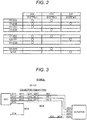
- Fig. 2 shows the matrix table.
- Fig. 3 shows the actual wiring diagram.
- Fig. 4 shows the connector diagram. Since the vehicle specification information and the wiring information for each auxiliary device have already been described, description thereof will be omitted.
- the matrix table is information created based on the vehicle specification information created for each of vehicles of various vehicle types.
- the matrix table is the information describing corresponding relationship between a number identifying a wire harness and specification required for each wire harness. As shown in Fig. 2 , in the matrix table referred to in the invention, the corresponding relationship is described by a matrix in which "wire harness numbers” (111-AAA, 111-BBB...141-III) are arranged in a vertical direction and “specification codes” (XXX, YYY and ZZZ) and are arranged in a horizontal direction.
- the number of the "wire harness numbers” and the "specification codes” is set to be larger than that of the matrix table shown in Fig. 2 . However, in the embodiment, the number thereof is reduced for easy understanding of the invention.
- Wire harnesses are divided and arranged for each space (engine room, instrument panel area, vehicle interior wall, trunk room and the like. Hereinafter these areas will be referred to as divided areas.) into which vehicle space is divided by function.
- a circuit network is formed in which electrical connection necessary for electrical components installed at various parts of the vehicle is made.
- a connection mode of connecting the wire harnesses wired in the adjacent divided areas via connectors provided at end portions of both the wire harnesses is referred to as "W to W (Wire to Wire)" in the specification.
- W to W Wire to Wire
- wire harnesses corresponds to different vehicle specification depending on the vehicle grade, the destination where the vehicle is driven, presence or absence of the electrical system that can be additionally mounted on the vehicle, or the like, a plurality of candidates for the wire harnesses that can be wired in each divided area are prepared.
- the wire harness numbers in the specification identify which candidate the wire harnesses are by a character string after "-(hyphen)".
- the wire harnesses constitute a circuit network that connects various electrical components mounted on the vehicle to construct various electrical systems. As described above, the wire harnesses are divided for each divided area, and electrical systems constructed by vehicle specification are increased or decreased. Therefore, for each wire harness, an electrical system in which the wire harness is involved in a circuit configuration is different. Therefore, a specification code is assigned to identify in which circuit configuration of the electrical system each wire harness is involved. Examples of the specification code include code for identifying the electrical system such as a headlamp system, an air bag system, an air conditioning system, an engine control system, an anti-lock brake system, a steering system and a wiper system. In the matrix table shown in Fig. 2 , three specification codes XXX, YYY and ZZZ are arranged in the horizontal direction.
- the actual wiring diagram is information created based on the wiring information for each auxiliary device and the matrix table, and is created for each of the above-described electrical systems.
- the actual wiring diagram describes and adds information on the electric wires to the circuit wires described in the wiring information for each auxiliary device, and the information on the circuit wires is sorted for each divided area.
- the actual wiring diagram describes information on a terminal or a connector that is connected to a terminal of electric component at the start point and the end point of the circuit wire.
- the actual wiring diagram describes information on each electric wire located in a divided area and information (information indicating a case where an electric wire end portion is connected by welding or abut crimping) on an auxiliary device such as a connector for connecting electric wire end portions located in respective divided areas, an Electronic Control Unit (ECU) Junction Box (JB), a Joint Connector (JC) and the like.
- ECU Electronic Control Unit
- JB Joint Connector
- JC Joint Connector
- the actual wiring diagram shown in Fig. 3 is described with respect to an electrical system "SYSTEM 1" to which the specification code XXX is assigned in the matrix table shown in Fig. 2 .
- the "SYSTEM 1" is an electrical system that mainly controls ACTUATOR located on a right side of Fig. 3 by ECU located on a left side of Fig. 3 . It is described that the ECU is provided with terminals E111, E112, E113 and E114. In addition, it is described that the ACTUATOR is provided with terminals A211, A212, A213 and A214.
- the ECU is powered from a terminal V114 to the terminal E114 via a power supply wire W114, and the ACTUATOR is powered from a terminal V214 to the terminal A214 via a power supply wire W214.
- the actual wiring diagram shown in Fig. 3 describes connectors CONNECTOR 1 and CONNECTOR 2, and a plurality of terminals S111, S112, S113, S211, S212 and S213 directly below description of "111 ⁇ 121".
- the actual wiring diagram describes and adds the information on the electric wires to the circuit wires described in the wiring information for each auxiliary device, and the information on the circuit wires is sorted for each divided area and the wire harnesses are in the W to W connection.
- the connector diagram describes the specification such as a number, a terminal accommodated in a housing, a cavity in which the terminal is accommodated, color of the housing and the like for all connectors constituting the wire harnesses.
- Fig. 4 is the connector diagram describing specification of the connector CONNECTOR 1 and the connector CONNECTOR 2 described in the actual wiring diagram of Fig. 3 .
- connector shapes are drawn as a plan view as viewed from a front side of fitting a target connector to a mating connector.
- six cavities are formed as specification of the connector CONNECTOR 1
- the terminals S111 to S113 are defined to be respectively accommodated in three cavities located at an upper stage.
- the connector CONNECTOR 2 is provided in a circuit that realizes an electrical system to which the specification code "XXX" is assigned.
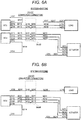
- Fig. 5A shows an actual wiring diagram of SYSTEM 2
- Fig. 5B shows an actual wiring diagram of SYSTEM 3.
- the "SYSTEM 2" is an electrical system that mainly controls LOAD located on a right side of Fig. 5A by ECU located on a left side of Fig. 5A . It is described that the ECU is provided with terminals E115, E116 and E117. In addition, it is described that the LOAD is provided with terminals L215, L216 and L217. The ECU is powered from a terminal V117 to the terminal E117 via a power supply wire W117, and the LOAD is powered from a terminal V217 to the terminal L217 via a power supply wire W217.
- the "SYSTEM 3" is an electrical system in which electric power is supplied from a terminal V118 located on a left side of Fig. 5B to a terminal L218 of LOAD located on a right side of Fig. 5B via wires W118 and W218.
- a wire harness 111-AAA includes circuit wires that realize the "SYSTEM 1" and the "SYSTEM 2”
- a wire harness 111-BBB includes circuit wires that realize the "SYSTEM 1” and the “SYSTEM 3”
- a wire harness 111-CCC includes circuit wires that realize only the "SYSTEM 1”.
- a wire harness 121-EEE includes circuit wires that realize the "SYSTEM 1" and the "SYSTEM 2”
- a wire harness 121-FFF includes circuit wires that realize the "SYSTEM 1” and the “SYSTEM 3”
- a wire harness 121-GGG includes circuit wires that realize only the "SYSTEM 1”.
- Fig. 6A shows an actual wiring diagram in which the "SYSTEM 1” and the "SYSTEM 2" are integrated
- Fig. 6B shows an actual wiring diagram in which the "SYSTEM 1” and the "SYSTEM 3” are integrated. In the actual wiring diagram in which the "SYSTEM 1" and the "SYSTEM 2" are integrated as shown in Fig.
- the terminals S111, S112, S113, S211, S212 and S213 of the "SYSTEM 1", and terminals S115, S116, S215, and S216 of the "SYSTEM 2" are in the W to W connection by the same connectors CONNECTOR 1 and CONNECTOR 2.
- the terminals S111, S112, S113, S211, S212 and S213 of the "SYSTEM 1" and terminals S118 and S218 of the "SYSTEM 3" are in the W to W connection by the same connectors CONNECTOR 1 and CONNECTOR 2.
- FIG. 7A shows a connector diagram of the SYSTEM 1
- Fig. 7B shows a connector diagram used for the "SYSTEM 1” and the "SYSTEM 2”
- Fig. 7C shows a connector diagram used for the "SYSTEM 1" and the "SYSTEM 3”.
- Fig. 7 describes the connector diagram ( Fig. 7A ) including the circuit wires that realize the "SYSTEM 1”
- the connector diagram ( Fig. 7B ) including the circuit wires that realize the "SYSTEM 1” and the "SYSTEM 2” and the connector diagram ( Fig.
- FIG. 7C including the circuit wires realize the "SYSTEM 1" and the "SYSTEM 3" as different connector diagrams.
- a specification code corresponding to the electrical system is described in association.
- the connector diagram shown in Fig. 7A describes the specification code "XXX” corresponding to the "SYSTEM 1" in association with the connectors CONNECTOR 1 and CONNECTOR 2.
- Fig. 7B and 7C in the connector diagrams when circuit wires used in a plurality of electrical systems are in the W to W connection by certain connectors, specification codes corresponding to the electrical systems are described in association.
- the connector diagram describes a terminal accommodated in a cavity for each cavity formed in the connector.
- the terminals S111, S112 and S113 are described with respect to the connector CONNECTOR 1, and the terminals S211, S212 and S213 are described with respect to the connector CONNECTOR 2.
- the terminals S111, S112, S113, S115 and S116 are described with respect to the connector CONNECTOR 1, and the terminals S211, S212, S213, S215 and S216 are described with respect to the connector CONNECTOR 2.
- the terminals S111, S112, S113 and S118 are described with respect to the connector CONNECTOR 1
- the terminals S211, S212, S213 and S218 are described with respect to the connector CONNECTOR 2.
- Fig. 8 is a flowchart showing the flow of the processing according to the wire harness conduction inspection method of the invention.
- connection part detection step in the specification a connection part of the W to W connection in the actual wiring diagram is detected.
- a part where the wire harnesses are in the W to W connection is described in the actual wiring diagram. Specifically, by detecting the character string "111 ⁇ 121" or a symbol with two consecutive marks indicating terminals as shown in Fig.3 , the connection part of the W to W connection is detected.
- each wire harness includes the electric wires constituting various electrical systems, and the circuit wires of various electrical systems may be realized across two wire harnesses at one connection part of the W to W connection as shown in Fig. 6 . Therefore, it is preferable to specify connectors that enable the W to W connection, and to perform the conduction inspection on the connector basis.
- connection part of the W to W connection is "111 ⁇ 121" in the above-described connection part detection step S801
- the wire harness wired in the divided area "111" and the wire harness wired in the divided area "121" are extracted with reference to the matrix table shown in Fig. 2 .
- wire harnesses having the numbers "111-AAA”, “111-BBB”, “111-CCC” and “111-DDD” are extracted as the wire harnesses wired in the divided area "111”.
- wire harnesses having the numbers "121-EEE”, “121-FFF” and “121-GGG” are extracted as the wire harnesses wired in the divided area "121".
- wire harness "111-BBB” wired in the divided area "111” and the wire harness “121-FFF” wired in the divided area “121” coincide with each other in the specification codes “XXX” and “ZZZ”.
- wire harness "111-CCC” wired in the divided area "111” and the wire harness "121-GGG” wired in the divided area “121” coincide with each other in the specification code "XXX”. Three pairs are specified in this way.
- connectors that performs the W to W connection on the pair of wire harnesses is specified with reference to the connector diagram (S803, referred to as a connector specification step in the specification).
- the specification codes are described in association with the connectors CONNECTOR 1 and CONNECTOR 2 in the connector diagrams.
- a specification code in which the pair coincides with each other can be specified. Therefore, when the pair including the wire harness wired in the divided area "111" and the wire harness wired in the divided area "121” is specified as described above, the connectors used for the W to W connection can be specified from the connector diagram by following the common specification code.
- the specification codes "XXX” and “ZZZ” are associated with the connectors CONNECTOR 1 and CONNECTOR 2 in the connector diagram shown in Fig. 7C .
- the connectors CONNECTOR 1 and CONNECTOR 2 shown in Fig. 7C are specified as being used for the W to W connection.
- the pair of the wire harness "111-CCC" wired in the divided area "111" and the wire harness "121-GGG" wired in the divided area "121” coincides with each other in the specification code "XXX”.
- the specification code "XXX” is associated with the connectors CONNECTOR 1 and CONNECTOR 2 as shown from Figs. 7A to 7C .
- one connector CONNECTOR 1 shown in Fig. 7A may be used for the W to W connection with each of the three connectors CONNECTOR 2 shown in Figs. 7A to 7C .
- 7B or 7C may be used for the W to W connection with each of the three connectors CONNECTOR 2 shown in Figs. 7A to 7C .
- nine patterns are specified as the connectors used for the W to W connection.
- the connectors used for the W to W connection are specified. Then, the connectors become targets of the conduction inspection by [processing of determining conduction success/failure of circuit wire] described below.
- processing of verifying conduction success/failure of a circuit wire is performed after the connectors CONNECTOR 1 and CONNECTOR 2 used for the W to W connection are fitted (S804, referred to as a conduction determination step in the specification).
- the connectors additionally include a correspondence table indicating corresponding relationship between the two fitted connectors.
- the correspondence table is used to indicate the corresponding relationship between a connector number assigned to a certain connector and a connector number assigned to another connector fitted to the connector.
- CONNECTOR 1 and CONNECTOR 2 are identifiers assigned to the connectors, and in practice the identifiers correspond to the numbers assigned to the connectors. Therefore, when it is described that the numbers of the connectors CONNECTOR 1 and CONNECTOR 2 are searched in the correspondence table described above, and the two numbers correspond to each other, it is determined that the connectors CONNECTOR 1 and CONNECTOR 2 can be fitted from a viewpoint of housing shape. When it is described that the two numbers do not correspond to each other, it is determined that one or both of the connector CONNECTOR 1 and the connector CONNECTOR 2 are erroneously described in the connector diagram.
- a specification code is assigned to each connector in the connector diagram.
- the two connectors CONNECTOR 1 and CONNECTOR 2 used for the W to W connection should coincide with each other in some or all of the specification codes. Therefore, when some of the specification codes assigned to the connectors CONNECTOR 1 and CONNECTOR 2 coincide with each other, it is determined that the connectors CONNECTOR 1 and CONNECTOR 2 can be fitted from a viewpoint of specification code. When the assigned specification codes do not coincide, it is determined that one or both of the connector CONNECTOR 1 and the connector CONNECTOR 2 are erroneously described in the connector diagram or the matrix table.
- Housing color may be described in the connector diagram. There are several reasons why the housing is color-coded in this way, and more reasons can be cited, such as for easy distinction by the operator between the two connectors to connect the two wire harnesses wired on the vehicle during the W to W connection, for easy distinction of the connectors that are relatively important and include the circuit wires of important electric systems, and the like. Therefore, when the connectors CONNECTOR 1 and CONNECTOR 2 are described in the same color, it is determined that the connectors CONNECTOR 1 and CONNECTOR 2 can be fitted from a viewpoint of housing color. When the same color is not described, it is determined that one or both of the connector CONNECTOR 1 and the connector CONNECTOR 2 are erroneously described in the connector diagram.
- Each of the connectors CONNECTOR 1 and CONNECTOR 2 used for the W to W connection must include terminals that connect the circuit wires of the electrical systems specified by the assigned specification codes. In other words, the terminals described in the actual wiring diagram of the target electrical system must be described in the connector diagram. Therefore, in the success/failure determination, it is determined whether the connector diagram is short of terminals connecting the circuit wires of the target electrical system.
- the connectors CONNECTOR 1 and CONNECTOR 2 shown in the connector diagram of Fig. 7B are specified as being used for the W to W connection will be described as an example. In the connector diagram shown in Fig.
- terminals S111, S112, S113, S115 and S116 are described with respect to the connector CONNECTOR 1
- the terminals S211, S212, S213, S215 and S216 are described with respect to the connector CONNECTOR 2.
- the terminals S111 to S116 and S211 to S216 are terminals that connect the circuit wires of the electrical systems specified by the specification codes "XXX” and "YYY". In the actual wiring diagrams of the "SYSTEM 1" and the "SYSTEM 2" respectively shown in Fig.
- the connectors CONNECTOR 1 and CONNECTOR 2 shown in the connector diagram of Fig. 7C are specified as being used for the W to W connection will be described as an example.
- the terminals S111, S112, S113 and S118 are described with respect to the connector CONNECTOR 1
- the terminals S211, S212, S213 and S218 are described with respect to the connector CONNECTOR 2.
- the terminals S111 to S113, S118, S211 to S213 and S218 are terminals that connect the circuit wires of the electrical systems specified by the specification codes "XXX" and "ZZZ".
- the connector CONNECTOR 1 shown in the connector diagram of Fig. 7A and the connector CONNECTOR 2 shown in Fig. 7B are specified as being used for W to W connection will be described as an example.
- the connectors CONNECTOR 1 (the specification code "XXX") and CONNECTOR 2 (the specification codes “XXX” and "YYY" are in the W to W connection.
- the terminals S111, S112 and S113 are described with respect to the connector CONNECTOR 1, and in the connector diagram shown in Fig.
- the terminals S211, S212, S213, S215 and S 216 are described with respect to the connector CONNECTOR 2.
- the terminals S111, S112 and S113 are described with respect to the connector CONNECTOR 1
- the terminals S211, S212 and S213 are described with respect to the connector CONNECTOR 2.
- the connector diagram describes positional relationship between a cavity provided in the housing and a terminal accommodated in the cavity.
- identifiers A to F are respectively assigned to cavities in the connector CONNECTOR 1
- identifiers A' to F' are respectively assigned to cavities in the connector CONNECTOR 2. Since the connector diagram is drawn as a plan view as viewed from the front side of fitting the target connector to the mating connector, it is to be noted that positional relationship between cavities of the connector CONNECTOR 1 and the connector CONNECTOR 2 shown in Fig. 9 are horizontally inverted.
- a pair of terminals is accommodated in each pair of cavities A-A', B-B', C-C', D-D', E-E' and F-F' facing each other when the two connectors are fitted, and it is determined whether all the pairs of terminals coincide in relationship of the W to W connection part in the actual wiring diagram.
- one pair of the pairs of terminals does not coincide with each other, or a terminal is not present in a cavity of the mating connector, it is determined that the terminals are erroneously described in the actual wiring diagram or the connector diagram.
- the conduction inspection method according to the embodiment of the invention has been described above in detail. According to the conduction inspection method according to the embodiment of the invention, with reference to the matrix table, the actual wiring diagram and the connector diagram, the conduction inspection can be performed on the connection part of the W to W connection at the intermediate stage before the connector and wiring information for each portion is created, and the actual wiring diagram and the connector diagram as the intermediate deliverables can be verified. Since the connector and wiring information for each portion is required, the conduction inspection method disclosed in JP-A-2011-137800 , JP-A-2011-170454 and JP-A-2011-180115 in related art cannot be performed at the intermediate stage before the connector and wiring information for each portion is created once.
- the conduction inspection is performed on the connection part of the W to W connection by the conduction inspection method according to the embodiment of the invention, so that the manpower for creating the connector and wiring information for each portion can be reduced by lowering the frequency of correcting the connector and wiring information for each portion that has been generated so far.
- the wirings used for the W to W connection can be specified with high accuracy.
- the wire harness may include a plurality of connectors to which the same identifier is assigned. Only by specifying a connector, the connector may be not used for the W to W connection on which the conduction inspection is desired to perform.
- the connectors used for the W to W connection are specified in the wire harness specification step S802 and the connector specification step S803. Since the connectors used for the W to W connection can be specified by following the specification codes of the matrix table in this way, the connectors used for the W to W connection can be specified by the simple processing, and the inspection accuracy can be improved in order to perform the conduction inspection on the wirings that truly requires the conduction inspection.
- the information useful for the circuit designer can be provided by presenting the failed inspection items as well as the information having erroneous descriptions (one or more matrix tables, actual wiring diagrams and connector diagrams). Accordingly, the circuit designer can see where the erroneous description is located in a short time.
- the actual wiring diagram obtained by integrating these actual wiring diagrams as shown in Figs. 6A and 6B may be used as the target of the conduction inspection of the connection part of the W to W connection. In this way, the conduction inspection can be performed on the connection part of the W to W connection even with respect to an actual wiring diagram in which the circuit configuration of the electrical system is insufficient only by the wirings described in one actual wiring diagram.
Landscapes
- Physics & Mathematics (AREA)
- General Physics & Mathematics (AREA)
- Testing Of Short-Circuits, Discontinuities, Leakage, Or Incorrect Line Connections (AREA)
Abstract
Description
- The invention relates to a wire harness conduction inspection method and a wire harness conduction inspection program that perform conduction inspection on a circuit constituting a wire harness, during circuit design of the wire harness mounted on a vehicle by a computer.
-
JP-A-2011-137800 JP-A-2011-170454 JP-A-2011-180115 - A flow of circuit design of a wire harness by a computer will be described with reference to
Fig. 10. Fig. 10 is a schematic diagram showing the flow of the circuit design of the wire harness by the computer. - As shown in
Fig. 10 , during the circuit design of the wire harness, a circuit is designed by using wiring information for each auxiliary device and a matrix table that are created from vehicle specification information, and connector and wiring information for each portion is created as a deliverable. - The vehicle specification information is information serving as a start point of the circuit design of the wire harness and defining specification of a certain vehicle. The vehicle specification information describes an electrical system mounted on the vehicle for each condition such as vehicle grade or a region where the vehicle is used, and an electrical system that can be additionally mounted on the vehicle.
- The wiring information for each auxiliary device is information created based on the vehicle specification information. The wiring information for each auxiliary device is prepared for each electrical system that is mounted on the vehicle and independently driven, such as a headlamp system, an air bag system, an air conditioning system, an engine control system and an ABS system. In order to drive the electrical system, it is necessary to connect electrical components (for example, a battery, an Electronic Control Unit (ECU) and a drive device) constituting the electrical system by a signal wire, a power supply wire and a ground wire. The wiring information for each auxiliary device includes connection information of circuit wires, for example, a start point or an end point of an electric wire among the power supply wire and the ground wire is connected to which terminal of which electrical component and to which electric wire, and auxiliary information on an auxiliary device that connects electric wires such as the signal wire, the power supply wire and the ground wire with the electrical components.
- The matrix table is information created based on the vehicle specification information created for each of vehicles of various vehicle types. The matrix table is the information describing corresponding relationship between a number identifying a wire harness and specification required for each wire harness. The corresponding relationship may be described by the matrix having "product number column" and "specification code row".
- The circuit is designed by using the above-described wiring information for each auxiliary device and the matrix table, and the connector and wiring information for each portion is created as the deliverable. The circuit design using the wiring information for each auxiliary device and the matrix table will be described in more detail.
- Since the main object of the wiring information for each auxiliary device is to represent the circuit wires of the electrical system including a plurality of electrical components, information on the electric wires constituting the wire harness is not included. The matrix table associates the specification realized by the electrical system with the wire harness. Therefore, the circuit design of the wire harness is performed while the electrical system defined in the wiring information for each auxiliary device is fitted to the specification of the wire harness described in the matrix table. In this process, an actual wiring diagram and a connector diagram are created as intermediate deliverables, and the connector and wiring information for each portion is created from the actual wiring diagram and the connector diagram.
- In the inventions disclosed in
JP-A-2011-137800 JP-A-2011-170454 JP-A-2011-180115 JP-A-2011-137800 JP-A-2011-170454 JP-A-2011-180115 Fig. 10 ). - In the conduction inspection method disclosed in
JP-A-2011-137800 JP-A-2011-170454 JP-A-2011-180115 - The present invention is made in view of the above-described circumstances, and an object thereof is to provide a wire harness conduction inspection method and a wire harness conduction inspection program capable of performing conduction inspection at the intermediate stage before connector and wiring information for each portion is created once, during circuit design of a wire harness by a computer.
- According to an aspect of the invention,
- (1) A wire harness conduction inspection method performed by a computer includes determining whether wirings included in two wire harnesses arranged in adjacent divided areas are conducted by a connector that connects the two wire harnesses, based on an actual wiring diagram that describes wirings to drive a certain electrical system mounted on a vehicle, a matrix table that describes specification for a wire harness to identify the electrical system constituting a portion of a circuit, for each wire harness mounted on the vehicle, and a connector diagram that describes a connector, a corresponding relationship between the connector and the wirings, and specification for the connector to identify the electrical system constituting the portion of the circuit.
- (2) The wire harness conduction inspection method according to (1), includes:
- detecting the connector that connects the two wire harnesses with reference to the actual wiring diagram;
- specifying a pair of wire harnesses having common specification assigned to the wire harnesses among the wire harnesses wired in each of the adjacent divided areas with reference to the matrix table;
- specifying the connector to which specification identical to the common specification of the pair of wire harnesses specified in the wire harness specification step is assigned with reference to the connector diagram; and
- a conduction determination step of determining whether the wirings included in the two wire harnesses are conducted by the connector with reference to the connector diagram that describes the connector specified by the connector specification step and the actual wiring diagram that describes the wirings of the electrical system to which the common specification is assigned.
- (3) The wire harness conduction inspection method according to (2) further includes outputting conduction success/failure determined in the conduction determination step, and
wherein the result output step presents failed inspection items as well as one or more matrix tables, actual wiring diagrams and connector diagrams having erroneous descriptions when outputting the conduction failure. - (4) A wire harness conduction inspection program causes a computer to execute each step of the conduction inspection method according to any of (1) to (3).
- According to the wire harness conduction inspection method of a configuration of (1), with reference to the matrix table, the actual wiring diagram and the connector diagram, the conduction inspection can be performed on a connection part of W to W connection at the intermediate stage before the connector and wiring information for each portion is created, and the actual wiring diagram and the connector diagram as the intermediate deliverables can be verified. Accordingly, the manpower for creating the connector and wiring information for each portion can be reduced by lowering frequency of correcting the connector and wiring information for each portion that has been generated so far.
- According to the wire harness conduction inspection method of a configuration of (2), the wirings used for the W to W connection can be specified with high accuracy. The wire harness may include a plurality of connectors to which the same identifier is assigned. Only by specifying a connector, the connector may be not used for the W to W connection on which the conduction inspection is desired to perform. According to the invention, the connector used for the W to W connection is specified from the specification described in the matrix table. Therefore, the connector used for the W to W connection can be specified by simple processing, and inspection accuracy can be improved in order to perform the conduction inspection on the wirings that truly requires the conduction inspection.
- According to the wire harness conduction inspection method of a configuration of (3), when the circuit designer is notified that the conduction inspection fails, information useful for the circuit designer can be provided by presenting the failed inspection items as well as the information having erroneous descriptions (one or more matrix tables, actual wiring diagrams and connector diagrams).
- According to the wire harness conduction inspection program of a configuration of (4), with reference to the matrix table, the actual wiring diagram and the connector diagram, the conduction inspection can be performed on the connection part of the W to W connection at the intermediate stage before the connector and wiring information for each portion is created, and the actual wiring diagram and the connector diagram as the intermediate deliverables can be verified. Accordingly, the manpower for creating the connector and wiring information for each portion can be reduced by lowering frequency of correcting the connector and wiring information for each portion that has been generated so far.
- In the wire harness conduction inspection method and the wire harness conduction inspection program of the invention, during the circuit design of the wire harness by the computer, the conduction inspection can be performed at the intermediate stage before the connector and wiring information for each portion is created once.
- The invention has been briefly described as above. Details of the invention will be further clarified by reading a mode (hereinafter referred to as "embodiment") for carrying out the invention described below with reference to attached drawings.
-
-
Fig. 1 is a schematic diagram showing a flow of circuit design of a wire harness by a computer according to a wire harness conduction inspection method and a wire harness conduction inspection program of the invention. -
Fig. 2 shows a matrix table. -
Fig. 3 shows an actual wiring diagram. -
Fig. 4 shows a connector diagram. -
Fig. 5A shows an actual wiring diagram ofSYSTEM 2, andFig. 5B shows an actual wiring diagram ofSYSTEM 3. -
Fig. 6A is an actual wiring diagram obtained by integrating "SYSTEM 1" and "SYSTEM 2", andFig. 6B is an actual wiring diagram obtained by integrating "SYSTEM 1" and "SYSTEM 3". -
Figs. 7A to 7C show connector diagrams ofSYSTEM 1,SYSTEM 2, andSYSTEM 3. -
Fig. 8 is a flowchart showing a flow of processing according to the wire harness conduction inspection method of the invention. -
Fig. 9 is a connector diagram describing cavity positions. -
Fig. 10 is a schematic diagram showing the flow of the circuit design of the wire harness by the computer. - Specific embodiments of the invention will be described below with reference to the drawings.
- The inventor has verified cause of conduction failure by the conduction inspection using the wiring information for each auxiliary device, the matrix table and the connector and wiring information for each portion in related art, and has found that the cause may be due to the erroneous descriptions occurring in the actual wiring diagram and the connector diagram created as the intermediate deliverables. In consideration of this finding, by performing the conduction inspection on the actual wiring diagram and the connector diagram created as the intermediate deliverables in the process of creating the connector and wiring information for each portion, verification is performed during creation of the connector and wiring information for each portion, whereby the invention aims to reduce the manpower required to complete the connector and wiring information for each portion.
- Therefore, features of the wire harness conduction inspection method and the wire harness conduction inspection program of the invention will be briefly described at first with reference to
Fig. 1. Fig. 1 is a schematic diagram showing a flow of circuit design of a wire harness by a computer according to a wire harness conduction inspection method and a wire harness conduction inspection program of the invention. The flow of the circuit design of the wire harness is the same as the flow described with reference toFig. 10 . In the processing as a feature of the conduction inspection method of the invention, when the circuit design of the wire harness is performed by a computer, with reference to a matrix table, an actual wiring diagram and a connector diagram (shaded information inFig. 1 ), conduction inspection is performed on a connection part of W to W connection described below at the intermediate stage before connector and wiring information for each portion is created, and the actual wiring diagram and the connector diagram as the intermediate deliverables are verified. Hereinafter, the wire harness conduction inspection method of the invention and the conduction inspection method according to the wire harness conduction inspection program of the invention will be described in detail. - First, the matrix table, the actual wiring diagram and the connector diagram will be described with reference to
Figs. 2 to 4 , and then a flow of conduction inspection processing using the matrix table, the actual wiring diagram and the connector diagram will be described.Fig. 2 shows the matrix table.Fig. 3 shows the actual wiring diagram.Fig. 4 shows the connector diagram. Since the vehicle specification information and the wiring information for each auxiliary device have already been described, description thereof will be omitted. - The matrix table is information created based on the vehicle specification information created for each of vehicles of various vehicle types. The matrix table is the information describing corresponding relationship between a number identifying a wire harness and specification required for each wire harness. As shown in
Fig. 2 , in the matrix table referred to in the invention, the corresponding relationship is described by a matrix in which "wire harness numbers" (111-AAA, 111-BBB...141-III) are arranged in a vertical direction and "specification codes" (XXX, YYY and ZZZ) and are arranged in a horizontal direction. In an actual matrix table, the number of the "wire harness numbers" and the "specification codes" is set to be larger than that of the matrix table shown inFig. 2 . However, in the embodiment, the number thereof is reduced for easy understanding of the invention. - Here, a naming rule of the wire harness numbers described in the embodiment of the invention will be described. Wire harnesses are divided and arranged for each space (engine room, instrument panel area, vehicle interior wall, trunk room and the like. Hereinafter these areas will be referred to as divided areas.) into which vehicle space is divided by function. By connecting the wire harnesses wired in adjacent divided areas via a connector, a circuit network is formed in which electrical connection necessary for electrical components installed at various parts of the vehicle is made. A connection mode of connecting the wire harnesses wired in the adjacent divided areas via connectors provided at end portions of both the wire harnesses is referred to as "W to W (Wire to Wire)" in the specification. In order to identify the wire harnesses wired in each of the divided areas, the wire harness numbers in the specification identify in which divided area the wire harnesses are wired by a character string before "-(hyphen)".
- Since the wire harnesses corresponds to different vehicle specification depending on the vehicle grade, the destination where the vehicle is driven, presence or absence of the electrical system that can be additionally mounted on the vehicle, or the like, a plurality of candidates for the wire harnesses that can be wired in each divided area are prepared. The wire harness numbers in the specification identify which candidate the wire harnesses are by a character string after "-(hyphen)".
- Next, the specification codes described in the embodiment of the invention will be described. The wire harnesses constitute a circuit network that connects various electrical components mounted on the vehicle to construct various electrical systems. As described above, the wire harnesses are divided for each divided area, and electrical systems constructed by vehicle specification are increased or decreased. Therefore, for each wire harness, an electrical system in which the wire harness is involved in a circuit configuration is different. Therefore, a specification code is assigned to identify in which circuit configuration of the electrical system each wire harness is involved. Examples of the specification code include code for identifying the electrical system such as a headlamp system, an air bag system, an air conditioning system, an engine control system, an anti-lock brake system, a steering system and a wiper system. In the matrix table shown in
Fig. 2 , three specification codes XXX, YYY and ZZZ are arranged in the horizontal direction. - In the matrix table shown in
Fig. 2 , the corresponding relationship is described by the matrix in which the "wire harness numbers" are arranged in the vertical direction and the "specification codes" are arranged in the horizontal direction. A cell to which "O" is assigned indicates that specification for realizing an electrical system identified by a "specification code" is adopted by a wire harness identified by a "wire harness number". For example, the specification for realizing electrical systems identified by "XXX" and "YYY" is adopted by a wire harness identified by "111-AAA". Such a matrix table is created based on the vehicle specification information created for each of vehicles of various vehicle types. - The actual wiring diagram is information created based on the wiring information for each auxiliary device and the matrix table, and is created for each of the above-described electrical systems. The actual wiring diagram describes and adds information on the electric wires to the circuit wires described in the wiring information for each auxiliary device, and the information on the circuit wires is sorted for each divided area. When a certain circuit wire described in the wiring information for each auxiliary device is connected to a plurality of electrical components across a plurality of divided areas in the actual wiring diagram, the actual wiring diagram describes information on a terminal or a connector that is connected to a terminal of electric component at the start point and the end point of the circuit wire. Further, the actual wiring diagram describes information on each electric wire located in a divided area and information (information indicating a case where an electric wire end portion is connected by welding or abut crimping) on an auxiliary device such as a connector for connecting electric wire end portions located in respective divided areas, an Electronic Control Unit (ECU) Junction Box (JB), a Joint Connector (JC) and the like. As described above, the actual wiring diagram describing the information of the electric wires is created for each system mounted on the vehicle. Hereinafter, the actual wiring diagram will be described with reference to
Fig. 3 . - The actual wiring diagram shown in
Fig. 3 is described with respect to an electrical system "SYSTEM 1" to which the specification code XXX is assigned in the matrix table shown inFig. 2 . The "SYSTEM 1" is an electrical system that mainly controls ACTUATOR located on a right side ofFig. 3 by ECU located on a left side ofFig. 3 . It is described that the ECU is provided with terminals E111, E112, E113 and E114. In addition, it is described that the ACTUATOR is provided with terminals A211, A212, A213 and A214. The ECU is powered from a terminal V114 to the terminal E114 via a power supply wire W114, and the ACTUATOR is powered from a terminal V214 to the terminal A214 via a power supply wire W214. - The actual wiring diagram shown in
Fig. 3 describesconnectors CONNECTOR 1 andCONNECTOR 2, and a plurality of terminals S111, S112, S113, S211, S212 and S213 directly below description of "111×121". This means that wire harnesses wired in a dividedarea 111 and a dividedarea 121 are in the W to W connection via theconnectors CONNECTOR 1 andCONNECTOR 2, and electric wires W111, W112, W113, W211, W212 and W213 that constitute the respective wire harnesses are connected via the terminals S111, S112, S113, S211, S212 and S213. As described above, the actual wiring diagram describes and adds the information on the electric wires to the circuit wires described in the wiring information for each auxiliary device, and the information on the circuit wires is sorted for each divided area and the wire harnesses are in the W to W connection. - The connector diagram describes the specification such as a number, a terminal accommodated in a housing, a cavity in which the terminal is accommodated, color of the housing and the like for all connectors constituting the wire harnesses.
Fig. 4 is the connector diagram describing specification of theconnector CONNECTOR 1 and theconnector CONNECTOR 2 described in the actual wiring diagram ofFig. 3 . In the connector diagram shown inFig. 4 , connector shapes are drawn as a plan view as viewed from a front side of fitting a target connector to a mating connector. As shown inFig. 4 , six cavities are formed as specification of theconnector CONNECTOR 1, and the terminals S111 to S113 are defined to be respectively accommodated in three cavities located at an upper stage. Similarly, six cavities are formed as specification of theconnector CONNECTOR 2, and the terminals S211 to S213 are defined to be respectively accommodated in three cavities located at an upper stage. Further, it is described that theconnectors CONNECTOR 1 andCONNECTOR 2 are provided in a circuit that realizes an electrical system to which the specification code "XXX" is assigned. - The matrix table, the actual wiring diagram and the connector diagram have been described so far. The flow of the conduction inspection processing by the computer using the matrix table, the actual wiring diagram and the connector diagram will be described from now on.
- First, for easy understanding of the invention, description will be given on the actual wiring diagram and the connector diagram when a plurality of circuit wires in the actual wiring diagram to which different specification codes are assigned are in W to W connection at the same connection part. Here, it is assumed that the
SYSTEM 2 to which the specification code "YYY" shown in the matrix table ofFig. 2 is assigned and theSYSTEM 3 to which the specification code "ZZZ" is assigned are in the W to W connection at the connection part described inSYSTEM 1 shown inFig.3 . -
Fig. 5A shows an actual wiring diagram ofSYSTEM 2, andFig. 5B shows an actual wiring diagram ofSYSTEM 3. As shown inFig. 5A , the "SYSTEM 2" is an electrical system that mainly controls LOAD located on a right side ofFig. 5A by ECU located on a left side ofFig. 5A . It is described that the ECU is provided with terminals E115, E116 and E117. In addition, it is described that the LOAD is provided with terminals L215, L216 and L217. The ECU is powered from a terminal V117 to the terminal E117 via a power supply wire W117, and the LOAD is powered from a terminal V217 to the terminal L217 via a power supply wire W217. The "SYSTEM 3" is an electrical system in which electric power is supplied from a terminal V118 located on a left side ofFig. 5B to a terminal L218 of LOAD located on a right side ofFig. 5B via wires W118 and W218. - Here, among wire harnesses wired in the divided
area 111 in the matrix table shown inFig. 2 , a wire harness 111-AAA includes circuit wires that realize the "SYSTEM 1" and the "SYSTEM 2", a wire harness 111-BBB includes circuit wires that realize the "SYSTEM 1" and the "SYSTEM 3", and a wire harness 111-CCC includes circuit wires that realize only the "SYSTEM 1". Similarly, among wire harnesses wired in the dividedarea 121, a wire harness 121-EEE includes circuit wires that realize the "SYSTEM 1" and the "SYSTEM 2", a wire harness 121-FFF includes circuit wires that realize the "SYSTEM 1" and the "SYSTEM 3", and a wire harness 121-GGG includes circuit wires that realize only the "SYSTEM 1". For reference,Fig. 6A shows an actual wiring diagram in which the "SYSTEM 1" and the "SYSTEM 2" are integrated, andFig. 6B shows an actual wiring diagram in which the "SYSTEM 1" and the "SYSTEM 3" are integrated. In the actual wiring diagram in which the "SYSTEM 1" and the "SYSTEM 2" are integrated as shown inFig. 6A , the terminals S111, S112, S113, S211, S212 and S213 of the "SYSTEM 1", and terminals S115, S116, S215, and S216 of the "SYSTEM 2" are in the W to W connection by thesame connectors CONNECTOR 1 andCONNECTOR 2. Similarly, in the actual wiring diagram in which the "SYSTEM 1" and the "SYSTEM 3" are integrated as shown inFig. 6B , the terminals S111, S112, S113, S211, S212 and S213 of the "SYSTEM 1", and terminals S118 and S218 of the "SYSTEM 3" are in the W to W connection by thesame connectors CONNECTOR 1 andCONNECTOR 2. -
CONNECTOR 1 andCONNECTOR 2 used for the W to W connection are described in connector diagrams as shown inFigs. 7A to 7C. Fig. 7A shows a connector diagram of theSYSTEM 1,Fig. 7B shows a connector diagram used for the "SYSTEM 1" and the "SYSTEM 2", andFig. 7C shows a connector diagram used for the "SYSTEM 1" and the "SYSTEM 3".Fig. 7 describes the connector diagram (Fig. 7A ) including the circuit wires that realize the "SYSTEM 1", the connector diagram (Fig. 7B ) including the circuit wires that realize the "SYSTEM 1" and the "SYSTEM 2" and the connector diagram (Fig. 7C ) including the circuit wires realize the "SYSTEM 1" and the "SYSTEM 3" as different connector diagrams. In the connector diagram as shown inFig. 7A , when circuit wires used in a certain electrical system are in the W to W connection by certain connectors, a specification code corresponding to the electrical system is described in association. Specifically, the connector diagram shown inFig. 7A describes the specification code "XXX" corresponding to the "SYSTEM 1" in association with theconnectors CONNECTOR 1 andCONNECTOR 2. As shown inFig. 7B and 7C in the connector diagrams, when circuit wires used in a plurality of electrical systems are in the W to W connection by certain connectors, specification codes corresponding to the electrical systems are described in association. Specifically, in the connector diagram shown inFig. 7B , the specification codes "XXX" and "YYY" corresponding to the "SYSTEM 1" and the "SYSTEM 2" are described in association with theconnectors CONNECTOR 1 andCONNECTOR 2. In the connector diagram shown inFig. 7C , the specification codes "XXX" and "ZZZ" corresponding to the "SYSTEM 1" and the "SYSTEM 3" are described in association with theconnectors CONNECTOR 1 andCONNECTOR 2. - In addition, the connector diagram describes a terminal accommodated in a cavity for each cavity formed in the connector. Specifically, in the connector diagram shown in
Fig. 7A , the terminals S111, S112 and S113 are described with respect to theconnector CONNECTOR 1, and the terminals S211, S212 and S213 are described with respect to theconnector CONNECTOR 2. Similarly, in the connector diagram shown inFig. 7B , the terminals S111, S112, S113, S115 and S116 are described with respect to theconnector CONNECTOR 1, and the terminals S211, S212, S213, S215 and S216 are described with respect to theconnector CONNECTOR 2. Similarly, in the connector diagram shown inFig. 7C , the terminals S111, S112, S113 and S118 are described with respect to theconnector CONNECTOR 1, and the terminals S211, S212, S213 and S218 are described with respect to theconnector CONNECTOR 2. - When the actual wiring diagram and the connector diagram are described correctly, the W to W connection should be described in accordance with description rules shown in
Figs. 5 and7 . On the contrary, when a description is made different from the description rules in the actual wiring diagram and the connector diagram, it can be said that the description is a place where the conduction inspection fails. Hereinafter, the flow of processing according to the conduction inspection method of the invention will be described with reference toFig. 8. Fig. 8 is a flowchart showing the flow of the processing according to the wire harness conduction inspection method of the invention. - First, one actual wiring diagram is selected, and a connection part of the W to W connection in the actual wiring diagram is detected (S801, referred to as a connection part detection step in the specification). As described with reference to
Fig.3 , a part where the wire harnesses are in the W to W connection is described in the actual wiring diagram. Specifically, by detecting the character string "111×121" or a symbol with two consecutive marks indicating terminals as shown inFig.3 , the connection part of the W to W connection is detected. - The wire harnesses wired in the adjacent divided areas are connected at one connection part of the W to W connection. As described above, each wire harness includes the electric wires constituting various electrical systems, and the circuit wires of various electrical systems may be realized across two wire harnesses at one connection part of the W to W connection as shown in
Fig. 6 . Therefore, it is preferable to specify connectors that enable the W to W connection, and to perform the conduction inspection on the connector basis. - Therefore, first, a method for specifying the connector having the W to W connection will be described. When it is detected that the connection part of the W to W connection is "111×121" in the above-described connection part detection step S801, the wire harness wired in the divided area "111" and the wire harness wired in the divided area "121" are extracted with reference to the matrix table shown in
Fig. 2 . As a result, wire harnesses having the numbers "111-AAA", "111-BBB", "111-CCC" and "111-DDD" are extracted as the wire harnesses wired in the divided area "111". Similarly, wire harnesses having the numbers "121-EEE", "121-FFF" and "121-GGG" are extracted as the wire harnesses wired in the divided area "121". - Specification codes assigned to the wire harnesses having the numbers are compared with the wire harnesses extracted as described above, and a pair including a wire harness wired in the divided area "111" and a wire harness wired in the divided area "121" that coincide with each other in specification code is specified (S802, referred to as a wire harness specification step in the specification). As shown in
Fig. 2 , the wire harness "111-AAA" wired in the divided area "111" and the wire harness "121-EEE" wired in the divided area "121" coincide with each other in the specification codes "XXX" and "YYY". Similarly, the wire harness "111-BBB" wired in the divided area "111" and the wire harness "121-FFF" wired in the divided area "121" coincide with each other in the specification codes "XXX" and "ZZZ". Similarly, the wire harness "111-CCC" wired in the divided area "111" and the wire harness "121-GGG" wired in the divided area "121" coincide with each other in the specification code "XXX". Three pairs are specified in this way. - When the pair including the wire harness wired in the divided area "111" and the wire harness wired in the divided area "121" is specified as described above, subsequently, connectors that performs the W to W connection on the pair of wire harnesses is specified with reference to the connector diagram (S803, referred to as a connector specification step in the specification). As shown in
Fig. 7 , the specification codes are described in association with theconnectors CONNECTOR 1 andCONNECTOR 2 in the connector diagrams. When the pair including the wire harness wired in the divided area "111" and the wire harness wired in the divided area "121" is selected, a specification code in which the pair coincides with each other can be specified. Therefore, when the pair including the wire harness wired in the divided area "111" and the wire harness wired in the divided area "121" is specified as described above, the connectors used for the W to W connection can be specified from the connector diagram by following the common specification code. - This will be described in detail with reference to
Figs. 2 and7 . As shown inFig. 2 , the pair of the wire harness "111-AAA" wired in the divided area "111" and the wire harness "121-EEE" wired in the divided area "121" coincides with each other in the specification codes "XXX" and "YYY". In the connector diagrams shown inFig. 7 , the specification codes "XXX" and "YYY" are associated with theconnectors CONNECTOR 1 andCONNECTOR 2 in the connector diagram shown inFig. 7B . In this way, in the pair of the wire harness "111-AAA" wired in the divided area "111" and the wire harness "121-EEE" wired in the divided area "121", theconnectors CONNECTOR 1 andCONNECTOR 2 shown inFig. 7B are specified as being used for the W to W connection. Similarly, the pair of the wire harness "111-BBB" wired in the divided area "111" and the wire harness "121-FFF" wired in the divided area "121" coincides with each other in the specification codes "XXX" and "ZZZ". In the connector diagrams shown inFig. 7 , the specification codes "XXX" and "ZZZ" are associated with theconnectors CONNECTOR 1 andCONNECTOR 2 in the connector diagram shown inFig. 7C . In this way, in the pair of the wire harness "1111-BBB" wired in the divided area "111" and the wire harness "121-FFF" wired in the divided area "121", theconnectors CONNECTOR 1 andCONNECTOR 2 shown inFig. 7C are specified as being used for the W to W connection. - In addition, the pair of the wire harness "111-CCC" wired in the divided area "111" and the wire harness "121-GGG" wired in the divided area "121" coincides with each other in the specification code "XXX". In the connector diagrams shown in
Fig. 7 , the specification code "XXX" is associated with theconnectors CONNECTOR 1 andCONNECTOR 2 as shown fromFigs. 7A to 7C . In this case, oneconnector CONNECTOR 1 shown inFig. 7A may be used for the W to W connection with each of the threeconnectors CONNECTOR 2 shown inFigs. 7A to 7C . Similarly, oneconnector CONNECTOR 1 shown inFig. 7B or 7C may be used for the W to W connection with each of the threeconnectors CONNECTOR 2 shown inFigs. 7A to 7C . As described above, in the pair of the wire harness "111-CCC" wired in the divided area "111" and the wire harness "121-GGG" wired in the divided area "121", nine patterns are specified as the connectors used for the W to W connection. - As described above, the connectors used for the W to W connection are specified. Then, the connectors become targets of the conduction inspection by [processing of determining conduction success/failure of circuit wire] described below. Hereinafter, it will be described below that processing of verifying conduction success/failure of a circuit wire is performed after the
connectors CONNECTOR 1 andCONNECTOR 2 used for the W to W connection are fitted (S804, referred to as a conduction determination step in the specification). - Various items are used for determining whether conduction is enabled by the fitted two
connectors CONNECTOR 1 andCONNECTOR 2. Here, each of the items will be described. - The connectors additionally include a correspondence table indicating corresponding relationship between the two fitted connectors. Specifically, the correspondence table is used to indicate the corresponding relationship between a connector number assigned to a certain connector and a connector number assigned to another connector fitted to the connector. In the embodiment,
CONNECTOR 1 andCONNECTOR 2 are identifiers assigned to the connectors, and in practice the identifiers correspond to the numbers assigned to the connectors. Therefore, when it is described that the numbers of theconnectors CONNECTOR 1 andCONNECTOR 2 are searched in the correspondence table described above, and the two numbers correspond to each other, it is determined that theconnectors CONNECTOR 1 andCONNECTOR 2 can be fitted from a viewpoint of housing shape. When it is described that the two numbers do not correspond to each other, it is determined that one or both of theconnector CONNECTOR 1 and theconnector CONNECTOR 2 are erroneously described in the connector diagram. - A specification code is assigned to each connector in the connector diagram. The two
connectors CONNECTOR 1 andCONNECTOR 2 used for the W to W connection should coincide with each other in some or all of the specification codes. Therefore, when some of the specification codes assigned to theconnectors CONNECTOR 1 andCONNECTOR 2 coincide with each other, it is determined that theconnectors CONNECTOR 1 andCONNECTOR 2 can be fitted from a viewpoint of specification code. When the assigned specification codes do not coincide, it is determined that one or both of theconnector CONNECTOR 1 and theconnector CONNECTOR 2 are erroneously described in the connector diagram or the matrix table. - Housing color may be described in the connector diagram. There are several reasons why the housing is color-coded in this way, and more reasons can be cited, such as for easy distinction by the operator between the two connectors to connect the two wire harnesses wired on the vehicle during the W to W connection, for easy distinction of the connectors that are relatively important and include the circuit wires of important electric systems, and the like. Therefore, when the
connectors CONNECTOR 1 andCONNECTOR 2 are described in the same color, it is determined that theconnectors CONNECTOR 1 andCONNECTOR 2 can be fitted from a viewpoint of housing color. When the same color is not described, it is determined that one or both of theconnector CONNECTOR 1 and theconnector CONNECTOR 2 are erroneously described in the connector diagram. - Each of the
connectors CONNECTOR 1 andCONNECTOR 2 used for the W to W connection must include terminals that connect the circuit wires of the electrical systems specified by the assigned specification codes. In other words, the terminals described in the actual wiring diagram of the target electrical system must be described in the connector diagram. Therefore, in the success/failure determination, it is determined whether the connector diagram is short of terminals connecting the circuit wires of the target electrical system. Hereinafter, a case where theconnectors CONNECTOR 1 andCONNECTOR 2 shown in the connector diagram ofFig. 7B are specified as being used for the W to W connection will be described as an example. In the connector diagram shown inFig. 7B , the terminals S111, S112, S113, S115 and S116 are described with respect to theconnector CONNECTOR 1, and the terminals S211, S212, S213, S215 and S216 are described with respect to theconnector CONNECTOR 2. The terminals S111 to S116 and S211 to S216 are terminals that connect the circuit wires of the electrical systems specified by the specification codes "XXX" and "YYY". In the actual wiring diagrams of the "SYSTEM 1" and the "SYSTEM 2" respectively shown inFig. 3 and5A , at the W to W connection part described as "111 × 121", the terminals S111, S112, S113, S115 and S116 are described with respect to theconnector CONNECTOR 1, and the terminals S211, S212, S213, S215 and S216 are described with respect to theconnector CONNECTOR 2. When the terminals described in the connector diagram shown inFig. 7B are compared with the terminals described in the actual wiring diagrams respectively shown inFigs. 3 and5A , there is no shortage in the terminals described in the connector diagram. When there is no shortage in the terminals described in the connector diagram by comparing the connector diagram and the actual wiring diagrams in this way, it is determined that the terminals located at the circuit wire end portions can be fitted when viewed from a viewpoint of specification. When there is shortage of terminals in the connector diagram, it is determined that the terminals are erroneously described in the actual wiring diagrams or the connector diagram. - Similarly, a case where the
connectors CONNECTOR 1 andCONNECTOR 2 shown in the connector diagram ofFig. 7C are specified as being used for the W to W connection will be described as an example. In the connector diagram shown inFig. 7C , the terminals S111, S112, S113 and S118 are described with respect to theconnector CONNECTOR 1, and the terminals S211, S212, S213 and S218 are described with respect to theconnector CONNECTOR 2. The terminals S111 to S113, S118, S211 to S213 and S218 are terminals that connect the circuit wires of the electrical systems specified by the specification codes "XXX" and "ZZZ". In the actual wiring diagrams of the "SYSTEM 1" and the "SYSTEM 3" respectively shown inFigs. 3 and5B , at the W to W connection part described as "111 × 121", the terminals S111, S112, S113 and S118 are described with respect to theconnector CONNECTOR 1, and the terminals S211, S212, S213 and S218 are described with respect to theconnector CONNECTOR 2. When the terminals described in the connector diagram shown inFig. 7C are compared with the terminals described in the actual wiring diagrams shown inFigs. 3 and5B , there is no shortage in the terminals described in the connector diagram. Therefore, it is determined that theconnectors CONNECTOR 1 andCONNECTOR 2 shown in the connector diagram ofFig. 7C are capable of fitting the terminals located at the circuit wire end portions when viewed from the viewpoint of specification. - Further, a case where the
connector CONNECTOR 1 shown in the connector diagram ofFig. 7A and theconnector CONNECTOR 2 shown inFig. 7B are specified as being used for W to W connection will be described as an example. In this example, in order to connect the circuit wires of the electrical system to which the specification code "XXX" is assigned, the connectors CONNECTOR 1 (the specification code "XXX") and CONNECTOR 2 (the specification codes "XXX" and "YYY") are in the W to W connection. In this case, in the connector diagram shown inFig. 7A , the terminals S111, S112 and S113 are described with respect to theconnector CONNECTOR 1, and in the connector diagram shown inFig. 7B , the terminals S211, S212, S213, S215 and S 216 are described with respect to theconnector CONNECTOR 2. In the actual wiring diagram of the "SYSTEM 1" shown inFig. 3 , at the W to W connection part described as "111 × 121", the terminals S111, S112 and S113 are described with respect to theconnector CONNECTOR 1, and the terminals S211, S212 and S213 are described with respect to theconnector CONNECTOR 2. When the terminals described in the connector diagrams shown inFigs. 7A and 7B are compared with the terminals described in the actual wiring diagram shown inFig. 3 , there is no shortage in the terminals described in the connector diagrams. Therefore, it is determined that theconnectors CONNECTOR 1 shown in the connector diagramFig. 7A andCONNECTOR 2 shown in the connector diagramFig. 7B are capable of fitting the terminals located at the circuit wire end portions when viewed from the viewpoint of specification. - The connector diagram describes positional relationship between a cavity provided in the housing and a terminal accommodated in the cavity. When it is determined that fitting is possible by the above-described [success/failure determination according to presence/absence of terminals located at circuit wire end portions] and all the terminals used for the W to W connection exist, subsequently, it is determined whether the cavity positions of the terminals provided in the
connector CONNECTOR 1 and the terminals provided in theconnector CONNECTOR 2 correspond to each other. In other words, it is determined whether a pair of terminals described as connecting in the actual wiring diagram is accommodated in a pair of cavities facing each other when theconnectors CONNECTOR 1 andCONNECTOR 2 are fitted. Specifically, in a connector diagram describing cavity positions shown inFig. 9 , identifiers A to F are respectively assigned to cavities in theconnector CONNECTOR 1, and identifiers A' to F' are respectively assigned to cavities in theconnector CONNECTOR 2. Since the connector diagram is drawn as a plan view as viewed from the front side of fitting the target connector to the mating connector, it is to be noted that positional relationship between cavities of theconnector CONNECTOR 1 and theconnector CONNECTOR 2 shown inFig. 9 are horizontally inverted. It is specified that a pair of terminals is accommodated in each pair of cavities A-A', B-B', C-C', D-D', E-E' and F-F' facing each other when the two connectors are fitted, and it is determined whether all the pairs of terminals coincide in relationship of the W to W connection part in the actual wiring diagram. When all the pairs of terminals coincide with each other, it is determined that the terminals can be fitted from a viewpoint of terminal accommodation position in cavity. When one pair of the pairs of terminals does not coincide with each other, or a terminal is not present in a cavity of the mating connector, it is determined that the terminals are erroneously described in the actual wiring diagram or the connector diagram. - When all the inspection items of the above-described [processing of determining conduction success/failure of circuit wire] are accepted, it is determined that the actual wiring diagram and the connector diagram concerning W to W targeted this time are correct, and the circuit designer is notified that the conduction inspection is successful (S805, referred to as a result output step in the specification). When any inspection item of the above-described [processing of determining conduction success/failure of circuit wire] is rejected, it is determined that there is an error in the description of the actual wiring diagram and the connector diagram concerning the W to W targeted this time, and the circuit designer is notified that the conduction inspection fails. When the circuit designer is notified that the conduction inspection fails, at the same time it is better to present failed inspection items, information having erroneous descriptions (one or more matrix tables, actual wiring diagrams and connector diagrams) and description place of the information.
- The conduction inspection method according to the embodiment of the invention has been described above in detail. According to the conduction inspection method according to the embodiment of the invention, with reference to the matrix table, the actual wiring diagram and the connector diagram, the conduction inspection can be performed on the connection part of the W to W connection at the intermediate stage before the connector and wiring information for each portion is created, and the actual wiring diagram and the connector diagram as the intermediate deliverables can be verified. Since the connector and wiring information for each portion is required, the conduction inspection method disclosed in
JP-A-2011-137800 JP-A-2011-170454 JP-A-2011-180115 - According to the conduction inspection method according to the embodiment of the invention, the wirings used for the W to W connection can be specified with high accuracy. The wire harness may include a plurality of connectors to which the same identifier is assigned. Only by specifying a connector, the connector may be not used for the W to W connection on which the conduction inspection is desired to perform. According to the invention, the connectors used for the W to W connection are specified in the wire harness specification step S802 and the connector specification step S803. Since the connectors used for the W to W connection can be specified by following the specification codes of the matrix table in this way, the connectors used for the W to W connection can be specified by the simple processing, and the inspection accuracy can be improved in order to perform the conduction inspection on the wirings that truly requires the conduction inspection.
- According to the conduction inspection method according to the embodiment of the invention, when the circuit designer is notified that the conduction inspection fails, the information useful for the circuit designer can be provided by presenting the failed inspection items as well as the information having erroneous descriptions (one or more matrix tables, actual wiring diagrams and connector diagrams). Accordingly, the circuit designer can see where the erroneous description is located in a short time.
- In the actual wiring diagram, wirings are described on one side of the divided area in description of the connection part of the W to W connection, while wirings are not described on the other side of the divided area. In other words, the circuit configuration of the electrical system is insufficient only by the wirings described in the single actual wiring diagram. Such an actual wiring diagram is generated because the wirings located on the other side are shared by the wirings used in another electrical system. In such an actual wiring diagram, since there is no information on the connector and the terminals located on the other side, the conduction inspection can be performed on the connection part of the W to W connection only with the actual wiring diagram.
- However, even if there is no description of one of the connectors used for the W to W connection in the actual wiring diagram X, when another actual wiring diagram Y has a description about one of the connectors, the actual wiring diagram obtained by integrating these actual wiring diagrams as shown in
Figs. 6A and 6B may be used as the target of the conduction inspection of the connection part of the W to W connection. In this way, the conduction inspection can be performed on the connection part of the W to W connection even with respect to an actual wiring diagram in which the circuit configuration of the electrical system is insufficient only by the wirings described in one actual wiring diagram. - Here, the features of the wire harness conduction inspection method and the wire harness conduction inspection program according to the above-described invention will be briefly summarized in the following [1] to [4] respectively.
- [1] A wire harness conduction inspection method,
wherein based on (i) an actual wiring diagram that describes wirings to drive a certain electrical system mounted on a vehicle, (ii) a matrix table that describes specification for a wire harness to identify the electrical system constituting a portion of a circuit, for each wire harness mounted on the vehicle, and (iii) a connector diagram that describes a connector, a corresponding relationship between the connector and the wirings, and specification for the connector to identify the electrical system constituting the portion of the circuit, a computer determines whether wirings included in two wire harnesses arranged in adjacent divided areas are conducted by a connector that connects the two wire harnesses. - [2] The wire harness conduction inspection method according to [1], comprising:
- a connection part detection step (S801) of detecting the connector that connects the two wire harnesses with reference to the actual wiring diagram;
- a wire harness specification step (S802) of specifying a pair of wire harnesses having common specification assigned to the wire harnesses among the wire harnesses wired in each of the adjacent divided areas with reference to the matrix table;
- a connector specification step(S803) of specifying the connector to which specification identical to the common specification of the pair of wire harnesses specified in the wire harness specification step is assigned with reference to the connector diagram; and
- a conduction determination step (S804) of determining whether the wirings included in the two wire harnesses are conducted by the connector with reference to the connector diagram that describes the connector specified by the connector specification step and the actual wiring diagram that describes the wirings of the electrical system to which the common specification is assigned.
- [3] The wire harness conduction inspection method according to [2],
wherein the wire harness conduction inspection method further includes a result output step (S805) of outputting conduction success/failure determined in the conduction determination step (S804), and
wherein the result output step (S805) presents failed inspection items as well as on or more matrix tables, actual wiring diagrams and connector diagrams having erroneous descriptions when outputting the conduction failure. - [4] A wire harness conduction inspection program,
wherein the wire harness conduction inspection program causes a computer to execute each step of the conduction inspection method according to any of [1] to [3].
Claims (4)
- A wire harness conduction inspection method performed by a computer comprising determining whether wirings included in two wire harnesses arranged in adjacent divided areas are conducted by a connector that connects the two wire harnesses, based on
an actual wiring diagram that describes wirings to drive a certain electrical system mounted on a vehicle,
a matrix table that describes specification for a wire harness to identify the electrical system constituting a portion of a circuit, for each wire harness mounted on the vehicle, and
a connector diagram that describes a connector, a corresponding relationship between the connector and the wirings, and specification for the connector to identify the electrical system constituting the portion of the circuit. - The wire harness conduction inspection method according to claim 1 further comprising:detecting the connector that connects the two wire harnesses with reference to the actual wiring diagram;specifying a pair of wire harnesses having common specification assigned to the wire harnesses among the wire harnesses wired in each of the adjacent divided areas with reference to the matrix table;specifying the connector to which specification identical to the common specification of the pair of wire harnesses specified in the wire harness specification step is assigned with reference to the connector diagram; anddetermining whether the wirings included in the two wire harnesses are conducted by the connector with reference to the connector diagram that describes the connector specified by the connector specification step and the actual wiring diagram that describes the wirings of the electrical system to which the common specification is assigned.
- The wire harness conduction inspection method according to claim 2 further comprising outputting conduction success/failure determined in the determining of the conduction of the wirings, and
wherein the result output step presents failed inspection items as well as at least one of matrix tables, actual wiring diagrams and connector diagrams having erroneous descriptions when outputting the conduction failure. - A wire harness conduction inspection program which causes a computer to execute each step of the conduction inspection method according to any of claims 1 to 3.
Applications Claiming Priority (1)
| Application Number | Priority Date | Filing Date | Title |
|---|---|---|---|
| JP2018119803A JP6793685B2 (en) | 2018-06-25 | 2018-06-25 | Wire harness continuity inspection method and wire harness continuity inspection program |
Publications (2)
| Publication Number | Publication Date |
|---|---|
| EP3594703A1 true EP3594703A1 (en) | 2020-01-15 |
| EP3594703B1 EP3594703B1 (en) | 2022-01-12 |
Family
ID=66625776
Family Applications (1)
| Application Number | Title | Priority Date | Filing Date |
|---|---|---|---|
| EP19175312.8A Not-in-force EP3594703B1 (en) | 2018-06-25 | 2019-05-20 | Wire harness conduction inspection method and wire harness conduction inspection program |
Country Status (4)
| Country | Link |
|---|---|
| US (1) | US10955452B2 (en) |
| EP (1) | EP3594703B1 (en) |
| JP (1) | JP6793685B2 (en) |
| CN (1) | CN110632446B (en) |
Families Citing this family (3)
| Publication number | Priority date | Publication date | Assignee | Title |
|---|---|---|---|---|
| JP7074726B2 (en) * | 2019-07-18 | 2022-05-24 | 矢崎総業株式会社 | Wire harness manufacturing system and wire harness manufacturing method |
| DE102020121614B4 (en) * | 2020-08-18 | 2022-05-25 | Lisa Dräxlmaier GmbH | Electrical connection arrangement for connecting freely configurable electrical components in a vehicle |
| JP7803991B2 (en) * | 2024-02-22 | 2026-01-21 | 株式会社図研 | Wire harness design support system, wire harness design support method, program, and computer-readable recording medium |
Citations (4)
| Publication number | Priority date | Publication date | Assignee | Title |
|---|---|---|---|---|
| JP2011137800A (en) | 2009-12-04 | 2011-07-14 | Yazaki Corp | Wire harness continuity inspection device, wire harness continuity inspection program, and wire harness continuity inspection method |
| JP2011170454A (en) | 2010-02-16 | 2011-09-01 | Yazaki Corp | Wire harness connnectivity inspection method and wire harness connnectivity inspection program |
| JP2011180115A (en) | 2010-02-08 | 2011-09-15 | Yazaki Corp | Wire harness connectivity inspection device, wire harness connectivity inspection program and wire harness connectivity inspection method inspection method |
| US20130061197A1 (en) * | 2010-05-28 | 2013-03-07 | Yazaki Corporation | Wire harness continuity inspection method and wire harness continuity inspection program |
Family Cites Families (6)
| Publication number | Priority date | Publication date | Assignee | Title |
|---|---|---|---|---|
| JP4008204B2 (en) * | 2001-04-12 | 2007-11-14 | 株式会社シンテックホズミ | Connection status presentation |
| JP2004200076A (en) * | 2002-12-19 | 2004-07-15 | Fujikura Ltd | Wire harness inspection device and inspection etc. processing method |
| CN1707484A (en) * | 2004-06-12 | 2005-12-14 | 鸿富锦精密工业(深圳)有限公司 | Wiring inspection system and method across cracks on motherboard |
| JP5586325B2 (en) * | 2010-05-28 | 2014-09-10 | 矢崎総業株式会社 | Wire harness continuity inspection method and wire harness continuity inspection program |
| US8547108B2 (en) * | 2010-11-24 | 2013-10-01 | Ziota Technology Inc. | Universal mate-in cable interface system |
| US9836573B2 (en) * | 2014-10-16 | 2017-12-05 | TATA TECHNOLOGIES PTE_Limited | Method and system for multilateral validation of wire harness design outputs |
-
2018
- 2018-06-25 JP JP2018119803A patent/JP6793685B2/en active Active
-
2019
- 2019-05-20 EP EP19175312.8A patent/EP3594703B1/en not_active Not-in-force
- 2019-05-21 US US16/417,773 patent/US10955452B2/en not_active Expired - Fee Related
- 2019-06-24 CN CN201910548077.5A patent/CN110632446B/en not_active Expired - Fee Related
Patent Citations (4)
| Publication number | Priority date | Publication date | Assignee | Title |
|---|---|---|---|---|
| JP2011137800A (en) | 2009-12-04 | 2011-07-14 | Yazaki Corp | Wire harness continuity inspection device, wire harness continuity inspection program, and wire harness continuity inspection method |
| JP2011180115A (en) | 2010-02-08 | 2011-09-15 | Yazaki Corp | Wire harness connectivity inspection device, wire harness connectivity inspection program and wire harness connectivity inspection method inspection method |
| JP2011170454A (en) | 2010-02-16 | 2011-09-01 | Yazaki Corp | Wire harness connnectivity inspection method and wire harness connnectivity inspection program |
| US20130061197A1 (en) * | 2010-05-28 | 2013-03-07 | Yazaki Corporation | Wire harness continuity inspection method and wire harness continuity inspection program |
Also Published As
| Publication number | Publication date |
|---|---|
| JP2020003852A (en) | 2020-01-09 |
| EP3594703B1 (en) | 2022-01-12 |
| CN110632446B (en) | 2021-09-21 |
| CN110632446A (en) | 2019-12-31 |
| US10955452B2 (en) | 2021-03-23 |
| JP6793685B2 (en) | 2020-12-02 |
| US20190391197A1 (en) | 2019-12-26 |
Similar Documents
| Publication | Publication Date | Title |
|---|---|---|
| EP3594703B1 (en) | Wire harness conduction inspection method and wire harness conduction inspection program | |
| CN111231865B (en) | Vehicle-mounted system | |
| JP5550455B2 (en) | Wire harness continuity inspection method and wire harness continuity inspection program | |
| JP5586325B2 (en) | Wire harness continuity inspection method and wire harness continuity inspection program | |
| JP2001093361A (en) | Method for manufacturing line structure having at least one cable harness | |
| CN102763106B (en) | Wire harness conduction inspection method | |
| BR102014030233A2 (en) | Vehicle inspection system and its control method | |
| US20230085351A1 (en) | Serviceable power inlet connector | |
| US9514579B2 (en) | Method and apparatus for checking vehicle specification | |
| US20190275966A1 (en) | Wire Harness Manufacturing Method and Wire Harness | |
| CN110855532A (en) | Vehicle-mounted gateway testing method, device, equipment and storage medium | |
| KR20230162358A (en) | Wiring connector for vehicle | |
| JP5557384B2 (en) | Wire harness continuity inspection method and wire harness continuity inspection program | |
| US7243326B2 (en) | Client-specific circuit board with isolated redundant systems | |
| JP7256048B2 (en) | Connection state detection method, connection state detection program, and design support device | |
| KR101950268B1 (en) | Verification apparatus for junction block circuit of vehicle and method thereof | |
| US20070049108A1 (en) | Hierarchical cable harness structure for a motor vehicle | |
| KR101040194B1 (en) | Apparatus and method for developing hardware topologies using verification-based process techniques in vehicle ECC systems | |
| CN116868544B (en) | Method for distributing electrical signals in a network | |
| JP2002357510A (en) | Electrical connection structure in automobile and method for inspecting function of internal combustion engine | |
| CN121328133A (en) | A Method for Developing Automotive Fault Diagnosis Processes Based on Design Changes | |
| KR100394670B1 (en) | Door electric field function inspection device of vehicle | |
| KR101950286B1 (en) | Apparatus for verifying wiring of vehicle and method thereof, computer program | |
| CN120540185A (en) | Modular PLC system configuration method, modular PLC system and electronic equipment | |
| CN116868544A (en) | Method for distributing electrical signals in a network |
Legal Events
| Date | Code | Title | Description |
|---|---|---|---|
| PUAI | Public reference made under article 153(3) epc to a published international application that has entered the european phase |
Free format text: ORIGINAL CODE: 0009012 |
|
| STAA | Information on the status of an ep patent application or granted ep patent |
Free format text: STATUS: REQUEST FOR EXAMINATION WAS MADE |
|
| 17P | Request for examination filed |
Effective date: 20190520 |
|
| AK | Designated contracting states |
Kind code of ref document: A1 Designated state(s): AL AT BE BG CH CY CZ DE DK EE ES FI FR GB GR HR HU IE IS IT LI LT LU LV MC MK MT NL NO PL PT RO RS SE SI SK SM TR |
|
| AX | Request for extension of the european patent |
Extension state: BA ME |
|
| REG | Reference to a national code |
Ref country code: DE Ref legal event code: R079 Ref document number: 602019010786 Country of ref document: DE Free format text: PREVIOUS MAIN CLASS: G01R0031040000 Ipc: B60R0016020000 |
|
| GRAP | Despatch of communication of intention to grant a patent |
Free format text: ORIGINAL CODE: EPIDOSNIGR1 |
|
| STAA | Information on the status of an ep patent application or granted ep patent |
Free format text: STATUS: GRANT OF PATENT IS INTENDED |
|
| RIC1 | Information provided on ipc code assigned before grant |
Ipc: G06F 113/16 20200101ALI20210915BHEP Ipc: G01R 31/69 20200101ALI20210915BHEP Ipc: B60R 16/02 20060101AFI20210915BHEP |
|
| INTG | Intention to grant announced |
Effective date: 20211014 |
|
| GRAS | Grant fee paid |
Free format text: ORIGINAL CODE: EPIDOSNIGR3 |
|
| GRAA | (expected) grant |
Free format text: ORIGINAL CODE: 0009210 |
|
| STAA | Information on the status of an ep patent application or granted ep patent |
Free format text: STATUS: THE PATENT HAS BEEN GRANTED |
|
| RIN1 | Information on inventor provided before grant (corrected) |
Inventor name: OHISHI, KOHTA |
|
| AK | Designated contracting states |
Kind code of ref document: B1 Designated state(s): AL AT BE BG CH CY CZ DE DK EE ES FI FR GB GR HR HU IE IS IT LI LT LU LV MC MK MT NL NO PL PT RO RS SE SI SK SM TR |
|
| REG | Reference to a national code |
Ref country code: GB Ref legal event code: FG4D |
|
| REG | Reference to a national code |
Ref country code: CH Ref legal event code: EP |
|
| REG | Reference to a national code |
Ref country code: DE Ref legal event code: R096 Ref document number: 602019010786 Country of ref document: DE |
|
| REG | Reference to a national code |
Ref country code: IE Ref legal event code: FG4D |
|
| REG | Reference to a national code |
Ref country code: AT Ref legal event code: REF Ref document number: 1462162 Country of ref document: AT Kind code of ref document: T Effective date: 20220215 |
|
| REG | Reference to a national code |
Ref country code: LT Ref legal event code: MG9D |
|
| REG | Reference to a national code |
Ref country code: NL Ref legal event code: MP Effective date: 20220112 |
|
| REG | Reference to a national code |
Ref country code: AT Ref legal event code: MK05 Ref document number: 1462162 Country of ref document: AT Kind code of ref document: T Effective date: 20220112 |
|
| PG25 | Lapsed in a contracting state [announced via postgrant information from national office to epo] |
Ref country code: NL Free format text: LAPSE BECAUSE OF FAILURE TO SUBMIT A TRANSLATION OF THE DESCRIPTION OR TO PAY THE FEE WITHIN THE PRESCRIBED TIME-LIMIT Effective date: 20220112 |
|
| PG25 | Lapsed in a contracting state [announced via postgrant information from national office to epo] |
Ref country code: SE Free format text: LAPSE BECAUSE OF FAILURE TO SUBMIT A TRANSLATION OF THE DESCRIPTION OR TO PAY THE FEE WITHIN THE PRESCRIBED TIME-LIMIT Effective date: 20220112 Ref country code: RS Free format text: LAPSE BECAUSE OF FAILURE TO SUBMIT A TRANSLATION OF THE DESCRIPTION OR TO PAY THE FEE WITHIN THE PRESCRIBED TIME-LIMIT Effective date: 20220112 Ref country code: PT Free format text: LAPSE BECAUSE OF FAILURE TO SUBMIT A TRANSLATION OF THE DESCRIPTION OR TO PAY THE FEE WITHIN THE PRESCRIBED TIME-LIMIT Effective date: 20220512 Ref country code: NO Free format text: LAPSE BECAUSE OF FAILURE TO SUBMIT A TRANSLATION OF THE DESCRIPTION OR TO PAY THE FEE WITHIN THE PRESCRIBED TIME-LIMIT Effective date: 20220412 Ref country code: LT Free format text: LAPSE BECAUSE OF FAILURE TO SUBMIT A TRANSLATION OF THE DESCRIPTION OR TO PAY THE FEE WITHIN THE PRESCRIBED TIME-LIMIT Effective date: 20220112 Ref country code: HR Free format text: LAPSE BECAUSE OF FAILURE TO SUBMIT A TRANSLATION OF THE DESCRIPTION OR TO PAY THE FEE WITHIN THE PRESCRIBED TIME-LIMIT Effective date: 20220112 Ref country code: ES Free format text: LAPSE BECAUSE OF FAILURE TO SUBMIT A TRANSLATION OF THE DESCRIPTION OR TO PAY THE FEE WITHIN THE PRESCRIBED TIME-LIMIT Effective date: 20220112 Ref country code: BG Free format text: LAPSE BECAUSE OF FAILURE TO SUBMIT A TRANSLATION OF THE DESCRIPTION OR TO PAY THE FEE WITHIN THE PRESCRIBED TIME-LIMIT Effective date: 20220412 |
|
| PGFP | Annual fee paid to national office [announced via postgrant information from national office to epo] |
Ref country code: DE Payment date: 20220329 Year of fee payment: 4 |
|
| PG25 | Lapsed in a contracting state [announced via postgrant information from national office to epo] |
Ref country code: PL Free format text: LAPSE BECAUSE OF FAILURE TO SUBMIT A TRANSLATION OF THE DESCRIPTION OR TO PAY THE FEE WITHIN THE PRESCRIBED TIME-LIMIT Effective date: 20220112 Ref country code: LV Free format text: LAPSE BECAUSE OF FAILURE TO SUBMIT A TRANSLATION OF THE DESCRIPTION OR TO PAY THE FEE WITHIN THE PRESCRIBED TIME-LIMIT Effective date: 20220112 Ref country code: GR Free format text: LAPSE BECAUSE OF FAILURE TO SUBMIT A TRANSLATION OF THE DESCRIPTION OR TO PAY THE FEE WITHIN THE PRESCRIBED TIME-LIMIT Effective date: 20220413 Ref country code: FI Free format text: LAPSE BECAUSE OF FAILURE TO SUBMIT A TRANSLATION OF THE DESCRIPTION OR TO PAY THE FEE WITHIN THE PRESCRIBED TIME-LIMIT Effective date: 20220112 Ref country code: AT Free format text: LAPSE BECAUSE OF FAILURE TO SUBMIT A TRANSLATION OF THE DESCRIPTION OR TO PAY THE FEE WITHIN THE PRESCRIBED TIME-LIMIT Effective date: 20220112 |
|
| PG25 | Lapsed in a contracting state [announced via postgrant information from national office to epo] |
Ref country code: IS Free format text: LAPSE BECAUSE OF FAILURE TO SUBMIT A TRANSLATION OF THE DESCRIPTION OR TO PAY THE FEE WITHIN THE PRESCRIBED TIME-LIMIT Effective date: 20220512 |
|
| REG | Reference to a national code |
Ref country code: DE Ref legal event code: R097 Ref document number: 602019010786 Country of ref document: DE |
|
| PG25 | Lapsed in a contracting state [announced via postgrant information from national office to epo] |
Ref country code: SM Free format text: LAPSE BECAUSE OF FAILURE TO SUBMIT A TRANSLATION OF THE DESCRIPTION OR TO PAY THE FEE WITHIN THE PRESCRIBED TIME-LIMIT Effective date: 20220112 Ref country code: SK Free format text: LAPSE BECAUSE OF FAILURE TO SUBMIT A TRANSLATION OF THE DESCRIPTION OR TO PAY THE FEE WITHIN THE PRESCRIBED TIME-LIMIT Effective date: 20220112 Ref country code: RO Free format text: LAPSE BECAUSE OF FAILURE TO SUBMIT A TRANSLATION OF THE DESCRIPTION OR TO PAY THE FEE WITHIN THE PRESCRIBED TIME-LIMIT Effective date: 20220112 Ref country code: EE Free format text: LAPSE BECAUSE OF FAILURE TO SUBMIT A TRANSLATION OF THE DESCRIPTION OR TO PAY THE FEE WITHIN THE PRESCRIBED TIME-LIMIT Effective date: 20220112 Ref country code: DK Free format text: LAPSE BECAUSE OF FAILURE TO SUBMIT A TRANSLATION OF THE DESCRIPTION OR TO PAY THE FEE WITHIN THE PRESCRIBED TIME-LIMIT Effective date: 20220112 Ref country code: CZ Free format text: LAPSE BECAUSE OF FAILURE TO SUBMIT A TRANSLATION OF THE DESCRIPTION OR TO PAY THE FEE WITHIN THE PRESCRIBED TIME-LIMIT Effective date: 20220112 |
|
| PLBE | No opposition filed within time limit |
Free format text: ORIGINAL CODE: 0009261 |
|
| STAA | Information on the status of an ep patent application or granted ep patent |
Free format text: STATUS: NO OPPOSITION FILED WITHIN TIME LIMIT |
|
| PG25 | Lapsed in a contracting state [announced via postgrant information from national office to epo] |
Ref country code: AL Free format text: LAPSE BECAUSE OF FAILURE TO SUBMIT A TRANSLATION OF THE DESCRIPTION OR TO PAY THE FEE WITHIN THE PRESCRIBED TIME-LIMIT Effective date: 20220112 |
|
| 26N | No opposition filed |
Effective date: 20221013 |
|
| REG | Reference to a national code |
Ref country code: CH Ref legal event code: PL |
|
| REG | Reference to a national code |
Ref country code: BE Ref legal event code: MM Effective date: 20220531 |
|
| PG25 | Lapsed in a contracting state [announced via postgrant information from national office to epo] |
Ref country code: MC Free format text: LAPSE BECAUSE OF FAILURE TO SUBMIT A TRANSLATION OF THE DESCRIPTION OR TO PAY THE FEE WITHIN THE PRESCRIBED TIME-LIMIT Effective date: 20220112 Ref country code: LU Free format text: LAPSE BECAUSE OF NON-PAYMENT OF DUE FEES Effective date: 20220520 Ref country code: LI Free format text: LAPSE BECAUSE OF NON-PAYMENT OF DUE FEES Effective date: 20220531 Ref country code: CH Free format text: LAPSE BECAUSE OF NON-PAYMENT OF DUE FEES Effective date: 20220531 |
|
| PG25 | Lapsed in a contracting state [announced via postgrant information from national office to epo] |
Ref country code: SI Free format text: LAPSE BECAUSE OF FAILURE TO SUBMIT A TRANSLATION OF THE DESCRIPTION OR TO PAY THE FEE WITHIN THE PRESCRIBED TIME-LIMIT Effective date: 20220112 |
|
| PG25 | Lapsed in a contracting state [announced via postgrant information from national office to epo] |
Ref country code: IE Free format text: LAPSE BECAUSE OF NON-PAYMENT OF DUE FEES Effective date: 20220520 Ref country code: FR Free format text: LAPSE BECAUSE OF NON-PAYMENT OF DUE FEES Effective date: 20220531 |
|
| PG25 | Lapsed in a contracting state [announced via postgrant information from national office to epo] |
Ref country code: BE Free format text: LAPSE BECAUSE OF NON-PAYMENT OF DUE FEES Effective date: 20220531 |
|
| PG25 | Lapsed in a contracting state [announced via postgrant information from national office to epo] |
Ref country code: IT Free format text: LAPSE BECAUSE OF FAILURE TO SUBMIT A TRANSLATION OF THE DESCRIPTION OR TO PAY THE FEE WITHIN THE PRESCRIBED TIME-LIMIT Effective date: 20220112 |
|
| REG | Reference to a national code |
Ref country code: DE Ref legal event code: R119 Ref document number: 602019010786 Country of ref document: DE |
|
| GBPC | Gb: european patent ceased through non-payment of renewal fee |
Effective date: 20230520 |
|
| PG25 | Lapsed in a contracting state [announced via postgrant information from national office to epo] |
Ref country code: MK Free format text: LAPSE BECAUSE OF FAILURE TO SUBMIT A TRANSLATION OF THE DESCRIPTION OR TO PAY THE FEE WITHIN THE PRESCRIBED TIME-LIMIT Effective date: 20220112 Ref country code: DE Free format text: LAPSE BECAUSE OF NON-PAYMENT OF DUE FEES Effective date: 20231201 Ref country code: CY Free format text: LAPSE BECAUSE OF FAILURE TO SUBMIT A TRANSLATION OF THE DESCRIPTION OR TO PAY THE FEE WITHIN THE PRESCRIBED TIME-LIMIT Effective date: 20220112 Ref country code: GB Free format text: LAPSE BECAUSE OF NON-PAYMENT OF DUE FEES Effective date: 20230520 |
|
| PG25 | Lapsed in a contracting state [announced via postgrant information from national office to epo] |
Ref country code: HU Free format text: LAPSE BECAUSE OF FAILURE TO SUBMIT A TRANSLATION OF THE DESCRIPTION OR TO PAY THE FEE WITHIN THE PRESCRIBED TIME-LIMIT; INVALID AB INITIO Effective date: 20190520 |
|
| PG25 | Lapsed in a contracting state [announced via postgrant information from national office to epo] |
Ref country code: MT Free format text: LAPSE BECAUSE OF FAILURE TO SUBMIT A TRANSLATION OF THE DESCRIPTION OR TO PAY THE FEE WITHIN THE PRESCRIBED TIME-LIMIT Effective date: 20220112 |
|
| PG25 | Lapsed in a contracting state [announced via postgrant information from national office to epo] |
Ref country code: TR Free format text: LAPSE BECAUSE OF FAILURE TO SUBMIT A TRANSLATION OF THE DESCRIPTION OR TO PAY THE FEE WITHIN THE PRESCRIBED TIME-LIMIT Effective date: 20220112 |