EP3594620A2 - Geolokalisierungsverfahren und system für seine umsetzung - Google Patents
Geolokalisierungsverfahren und system für seine umsetzung Download PDFInfo
- Publication number
- EP3594620A2 EP3594620A2 EP19180942.5A EP19180942A EP3594620A2 EP 3594620 A2 EP3594620 A2 EP 3594620A2 EP 19180942 A EP19180942 A EP 19180942A EP 3594620 A2 EP3594620 A2 EP 3594620A2
- Authority
- EP
- European Patent Office
- Prior art keywords
- code
- scanning device
- marker
- acquisition
- information
- Prior art date
- Legal status (The legal status is an assumption and is not a legal conclusion. Google has not performed a legal analysis and makes no representation as to the accuracy of the status listed.)
- Withdrawn
Links
Images
Classifications
-
- G—PHYSICS
- G01—MEASURING; TESTING
- G01C—MEASURING DISTANCES, LEVELS OR BEARINGS; SURVEYING; NAVIGATION; GYROSCOPIC INSTRUMENTS; PHOTOGRAMMETRY OR VIDEOGRAMMETRY
- G01C15/00—Surveying instruments or accessories not provided for in groups G01C1/00 - G01C13/00
- G01C15/02—Means for marking measuring points
-
- G—PHYSICS
- G01—MEASURING; TESTING
- G01C—MEASURING DISTANCES, LEVELS OR BEARINGS; SURVEYING; NAVIGATION; GYROSCOPIC INSTRUMENTS; PHOTOGRAMMETRY OR VIDEOGRAMMETRY
- G01C15/00—Surveying instruments or accessories not provided for in groups G01C1/00 - G01C13/00
- G01C15/002—Active optical surveying means
- G01C15/004—Reference lines, planes or sectors
-
- G—PHYSICS
- G06—COMPUTING OR CALCULATING; COUNTING
- G06K—GRAPHICAL DATA READING; PRESENTATION OF DATA; RECORD CARRIERS; HANDLING RECORD CARRIERS
- G06K19/00—Record carriers for use with machines and with at least a part designed to carry digital markings
- G06K19/06—Record carriers for use with machines and with at least a part designed to carry digital markings characterised by the kind of the digital marking, e.g. shape, nature, code
- G06K19/06009—Record carriers for use with machines and with at least a part designed to carry digital markings characterised by the kind of the digital marking, e.g. shape, nature, code with optically detectable marking
- G06K19/06018—Record carriers for use with machines and with at least a part designed to carry digital markings characterised by the kind of the digital marking, e.g. shape, nature, code with optically detectable marking one-dimensional coding
- G06K19/06028—Record carriers for use with machines and with at least a part designed to carry digital markings characterised by the kind of the digital marking, e.g. shape, nature, code with optically detectable marking one-dimensional coding using bar codes
-
- G—PHYSICS
- G06—COMPUTING OR CALCULATING; COUNTING
- G06K—GRAPHICAL DATA READING; PRESENTATION OF DATA; RECORD CARRIERS; HANDLING RECORD CARRIERS
- G06K19/00—Record carriers for use with machines and with at least a part designed to carry digital markings
- G06K19/06—Record carriers for use with machines and with at least a part designed to carry digital markings characterised by the kind of the digital marking, e.g. shape, nature, code
- G06K19/06009—Record carriers for use with machines and with at least a part designed to carry digital markings characterised by the kind of the digital marking, e.g. shape, nature, code with optically detectable marking
- G06K19/06037—Record carriers for use with machines and with at least a part designed to carry digital markings characterised by the kind of the digital marking, e.g. shape, nature, code with optically detectable marking multi-dimensional coding
-
- G—PHYSICS
- G06—COMPUTING OR CALCULATING; COUNTING
- G06T—IMAGE DATA PROCESSING OR GENERATION, IN GENERAL
- G06T17/00—Three dimensional [3D] modelling, e.g. data description of 3D objects
- G06T17/05—Geographic models
Definitions
- the present invention relates to geolocation methods and systems used in urban areas in particular, and methods for generating 3D models from surveys carried out in the environment of a terrestrial scan device.
- reception of the GPS signal can be difficult in certain dense urban or forest environments.
- Requirement WO2017 / 117667A1 describes a method for monitoring underground galleries aimed at correcting a drift in the estimated position of a mobile scanner located in the gallery over time and / or during its movement. Acquisitions of the gallery profile are taken at checkpoints by a laser scanner in the presence of an RFID chip providing a unique identifier for the acquisition, and the corresponding data are recorded in a database. These reference acquisitions can then be compared with the subsequent acquisitions made by the mobile scanner to correct the aforementioned drift problem.
- Requirement US2015 / 0170368 discloses a geolocation process based on the acquisition of images by a mobile telephone for example, and the search for a correlation between remarkable points of the images acquired by the telephone and a catalog of reference images in which these same points have been georeferenced.
- the method can include the selection on the image of the points that one seeks to geolocate. Such a method is highly dependent on the quality of image acquisition and the ability of the computer system to detect corresponding reference images.
- Said repository can be an absolute repository.
- absolute reference we mean a geodetic reference in which we can define the location of an object on earth unequivocally. Its center is for example close to the barycenter of the earth, its first two axes are in the plane of the equator and its third axis is close to the axis of rotation of the earth.
- the absolute reference system which can be used within the framework of the present invention is preferably chosen from the following: French Geodetic Network 1993 (RGF93), World Geodetic System (WGS84), International Terrestrial Rotational Service (ITRS) or European Terrestrial Reference System (ETRS).
- the code may include information on the positioning accuracy of the reference in said reference system or this information may be accessible via said database.
- the markers can be geolocated in said reference frame with an accuracy better than 40cm, better 10cm, even better 1cm.
- the landmarks can be disseminated over an area greater than 1 km 2 , and / or with a density greater than 100 per km 2 , and / or with a distance between two landmarks close to each other of between 5 and 100m.
- the code for each marker can be a bar code or a matrix code, in particular a QR code.
- the code can be protected by a glass or engraved or printed so as to resist weathering and solar radiation.
- the markers can be present on the facade of buildings, in particular on a plaque giving the building number or the name of a street.
- Each marker can include a catadioptric prism.
- terrestrial scanning device is meant any system allowing the implementation of the method according to the invention and in particular to acquire geometric information on a given environment.
- the terrestrial scanning device can rest on the ground at the time of acquisition, for example be mounted on a vehicle moving on the street, for example on the road, or carried manually by an operator.
- the terrestrial scanning device can image the facades of buildings and other infrastructures or equipment with a non-vertical line of sight from top to bottom, its line of sight during the scan being for example oblique from bottom to top or horizontal.
- the scanning device may include a memory for storing data transmitted by the topographic reference.
- the terrestrial scanning device can benefit from communication means allowing it to interrogate a database from the information read from the topographic reference.
- the image processing and localization systems can for example be the same specialized processor or the same microcomputer. At least part of the processing and calculations can be transferred to a remote server, for example integrated into a digital platform with which the scanning device is connected.
- the terrestrial scanning device may include any element known in laser scanning or photogrammetry devices.
- the scanning device can comprise at least one photo or video sensor for acquiring information in the form of 2D or 3D images or one or more static or dynamic laser scanners making it possible to acquire the information in the form of point clouds.
- the laser scanner can advantageously be associated with a photo or video sensor.
- the scanning device may include a laser rangefinder and / or a laser sighting device making it possible to point the scanning device at the geolocated reference point or at a point of interest whose position it is desired to know in said reference frame.
- the terrestrial scanning device can thus include at least one laser.
- the laser can help target a point of interest.
- the scanning device may include a lidar.
- the scanning device may include a camera to read the data present on the topography benchmark and / or to acquire an image of its immediate environment.
- the scanning device may include means for automatically scanning its environment, in particular by mechanically driving an optic.
- the terrestrial scanning device may include a telecommunications system with a remote computing platform enabling it to be provided with a identifier of the topographic marker geolocated by the scan device and to receive in return the position of the topographic marker in said reference frame.
- the terrestrial scanning device can include a tripod and an articulation making it possible to orient it in azimuth and elevation.
- the terrestrial scanning device may also include a radiofrequency system capable of reading information specific to the topographical reference, if necessary, when the latter is equipped with an RFID chip for example.
- the environment in question is preferably an outdoor urban area, comprising for example buildings such as apartment buildings or offices, individual houses, urban furniture such as street lamps, low beams, traffic signs, advertising signs, shelters or benches, among others.
- buildings such as apartment buildings or offices, individual houses, urban furniture such as street lamps, low beams, traffic signs, advertising signs, shelters or benches, among others.
- This acquisition can include a laser sighting of one or more geolocated topographical marks, from the same position of the scanning device, in order to read data carried by this mark and / or to identify it.
- the acquisition of spatial data can be carried out for example in the form of photogrammetric data, in particular from sets of images or video sequences, or in the form of lasergrammetric data.
- the acquisition can be carried out with at least one rotation of the scanning device on itself around an axis of rotation, preferably fixed during this rotation, or at using several sensors with different viewing axes.
- the acquisition may include an azimuth and elevation scan of the area whose geometry is sought to be acquired by the acquisition means.
- the acquisition can be carried out at a distance of at least 5m from at least one of said benchmarks, better still from at least 10m, or even from at least 20m.
- the acquisition can be carried out using at least one camera, equipped with a telescope for example, or with a lidar.
- the markers can be fixed on a building, a piece of equipment or a piece of pre-existing street furniture.
- the code may include a unique identifier of the marker, in particular in the form of a barcode or matrix code.
- Each marker may include a catadioptric prism, as mentioned above.
- the method of acquiring 3D data can also comprise the step consisting in interrogating a database, in particular a remote one, by supplying the identifier of the mark read by the scanning device, in order to obtain in return the position of the latter. in the given frame of reference, and preferably also obtain an indication of the positioning accuracy of the frame of reference in this frame of reference.
- the code readable by the scanning device may include the position of the marker in the given frame of reference, and preferably an indication of the positioning accuracy of the marker in this frame of reference.
- the method of acquiring 3D data can comprise the generation of a 3D model of the environment of the scanning device from at least knowledge of the position of the scanning device and an acquisition of the geometry of the environment of the scanning device.
- the acquisition by the scanning device can be carried out at a distance of at least 5m from at least one of said reference points whose code is read during said acquisition, better at least 10m, or even at least 20m.
- the 3D data acquisition process can include reading by the scanning device of the reference codes which are scattered over an area greater than 1 km 2 .
- the 3D data acquisition process may include reading by the scanning device of the reference codes disseminated with a density greater than 100 per km 2 .
- the 3D data acquisition process may include reading by the scanning device of the reference codes separated by a distance of between 5 and 100 m.
- the 3D data acquisition process may include reading by the scanning device of the reference codes positioned with a localization precision better than 0.4 m in said reference frame, better better than 0.2 m, even better better than 0 , 1 m, in particular between 1 and 10 cm.
- information is included in the code on the precision with which the position of the location intended to receive the reference point is known in said reference system.
- the topographic benchmarks are preferably geolocated in said reference frame with an accuracy better than 40cm, better 10cm, even better 1cm, the benchmarks being preferably spread over an area greater than 1 km 2 , and / or with a density greater than 100 per km 2 , and / or with a distance between two landmarks close to each other of between 5 and 100m.
- Each marker may include an optically readable code, in particular a bar code or a matrix code, in particular a QR code. This code can be protected by a window or be engraved or printed so as to resist weathering and solar radiation.
- Each marker may include a radio frequency electronic circuit adapted to communicate with the terrestrial scanning device. This can make it possible, for example, to speed up the automatic optical search for the topographic marker by the terrestrial scanning device, or to provide a unique identifier for the topographic marker if it does not include an optical code.
- At least part of the markers may be present on the facade of buildings, in particular on a plate giving the building number or the name of a street.
- the indication on the plate such as the number or the name of the street, can possibly be part of the immediate environment of the marker allowing its identification.
- the plate bearing the building number or the street name plate constitute geolocated landmarks within the meaning of the invention.
- Each marker may include a catadioptric prism, as mentioned above.
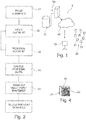
- This system comprises at least one terrestrial scan device 10 and a set 20 of topographical markers geolocated 21 by the terrestrial scan device 10.
- the system 1 can also include, as illustrated, a computer platform 30 with which the scanning device 10 can exchange data, for example via a telecommunications network 40 such as the GPRS network or the 3G or 4G network .
- a telecommunications network 40 such as the GPRS network or the 3G or 4G network .
- the topographical marks 21 can, as illustrated in the figure 4 , include a support 22 on which data is carried, for example in the form of a matrix code 23, for example of the QR code type.
- This code 23 may include the coordinates of the topographic reference point 21 in a given repository, or preferably a unique identifier of the topographic reference point, which is listed in a database 31 accessible via the computer platform 30.
- the support 22 is for example made of metal or plastic and it is for example provided for its attachment to a facade of a building.
- the topographic reference 21 can be produced in various ways and the invention is not limited to a particular type of support, nor to a way of carrying the information on the support 22.
- topographical landmarks 21 in the urban environment, which corresponds to step 51 on the figure 2 , by precisely determining their position, and using for this the conventional geolocation techniques available to topographers, for example a total station.
- the references 21 carry a unique identifier, for example a matrix code as illustrated in the figure 4
- the identifier of the reference frame is recorded in the base 31 as well as the position in said reference frame thereof. It is also possible to record in the base 31 the precision with which the position of the coordinate system is known in said reference system.
- the density of implantation of geolocated topographic benchmarks 21 is preferably large enough to allow viewing at least two of them in various locations in the urban environment where the terrestrial scanning device is likely to be arranged to carry out scouting before work or a scan of the existing.
- the area equipped with geolocated topographic landmarks can cover an entire district, and better still an entire city.
- the geolocated topographical marks Once the geolocated topographical marks have been placed, they can remain in place for a very long time, not being intended to be removed, but only replaced if necessary.
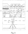
- the terrestrial scan device 10 it is possible to geolocate the terrestrial scan device 10 by coming to position it so that it can aim, or at least see, at least one of the topographic landmarks 21, as illustrated in the figure 3 , and better still at least two of said topographical references 21, which allows triangulation calculations.
- the aiming can be automatic, that is to say that the terrestrial scanning device 10 carries out a scanning of its environment and in so doing detects the presence of one or more topographical markers 21.
- the terrestrial scanning device 10 When the terrestrial scanning device 10 detects a topographic reference point 21, it can know the position of the latter in said reference frame, which corresponds to step 53 on the figure 2 .
- the terrestrial scan device 10 is able to recognize the topographic reference mark 21 by means of the code 23 that the scan device 10 can read on the topographic reference mark 21.
- This code can include the position of the topographic reference mark 21, which is encoded in a predefined manner allowing its reading by the terrestrial scan device 10, or a unique identifier of the topographic reference mark 21, in which case the terrestrial scan device can interrogate the base 31 in order to know in return the position of the topographic reference mark 21 in said reference frame .
- Steps 52 and 53 can be repeated for each of the topographical marks 21 detectable by the terrestrial scanning device 10.
- the position of the terrestrial scanning device can be determined by calculation in step 54, knowing the position of the tomographic markers 21 and the way in which they are seen from the terrestrial scanning device 10.
- the latter can be used for any type of survey or scan, in step 55.
- the data resulting from the surveys or scans carried out can be uploaded to the platform 30.
- the terrestrial scanning device 10 can be produced otherwise and the acquisition is carried out for example from a terrestrial vehicle or from a drone moving along a street.
- the optical acquisition of the topographic markers 21 can be carried out with or without laser sighting, and in one example this acquisition is carried out using one or more cameras only.
- the invention makes it possible to dispense with a satellite positioning of the scanning device, it remains possible to use a satellite positioning of the scanning device to help identify the marks 21 seen by the latter. . This is particularly interesting when the markers 21 are identified by their immediate environment. In this case, the catalog of reference images can be searched for those whose position is close to the position given by the satellite location, which can speed up the identification of the reference 21.
Landscapes
- Engineering & Computer Science (AREA)
- Physics & Mathematics (AREA)
- General Physics & Mathematics (AREA)
- Theoretical Computer Science (AREA)
- Remote Sensing (AREA)
- Software Systems (AREA)
- Geometry (AREA)
- Radar, Positioning & Navigation (AREA)
- Computer Graphics (AREA)
- Length Measuring Devices By Optical Means (AREA)
- Optical Radar Systems And Details Thereof (AREA)
- Position Fixing By Use Of Radio Waves (AREA)
- Radar Systems Or Details Thereof (AREA)
- Image Processing (AREA)
Applications Claiming Priority (1)
| Application Number | Priority Date | Filing Date | Title |
|---|---|---|---|
| FR1855329A FR3082643A1 (fr) | 2018-06-18 | 2018-06-18 | Procede de geolocalisation et systeme pour sa mise en œuvre |
Publications (2)
| Publication Number | Publication Date |
|---|---|
| EP3594620A2 true EP3594620A2 (de) | 2020-01-15 |
| EP3594620A3 EP3594620A3 (de) | 2021-03-17 |
Family
ID=63684027
Family Applications (1)
| Application Number | Title | Priority Date | Filing Date |
|---|---|---|---|
| EP19180942.5A Withdrawn EP3594620A3 (de) | 2018-06-18 | 2019-06-18 | Geolokalisierungsverfahren und system für seine umsetzung |
Country Status (5)
| Country | Link |
|---|---|
| US (1) | US11320262B2 (de) |
| EP (1) | EP3594620A3 (de) |
| AU (1) | AU2019204229A1 (de) |
| CA (1) | CA3046903A1 (de) |
| FR (1) | FR3082643A1 (de) |
Families Citing this family (2)
| Publication number | Priority date | Publication date | Assignee | Title |
|---|---|---|---|---|
| WO2018149474A1 (en) * | 2017-02-14 | 2018-08-23 | Trimble Ab | Geodetic surveying with time synchronization |
| US12175557B2 (en) | 2022-04-29 | 2024-12-24 | Trimble Inc. | Correcting position of a mobile device using a mobile reference |
Citations (4)
| Publication number | Priority date | Publication date | Assignee | Title |
|---|---|---|---|---|
| FR1993E (fr) | 1901-06-07 | 1903-11-24 | Societe Charpentier Fils Aine Et A. Neveu | Table scolaire |
| US8818076B2 (en) | 2005-09-01 | 2014-08-26 | Victor Shenkar | System and method for cost-effective, high-fidelity 3D-modeling of large-scale urban environments |
| US20150170368A1 (en) | 2009-09-14 | 2015-06-18 | Trimble Navigation Limited | Image-based georeferencing |
| WO2017117667A1 (en) | 2016-01-07 | 2017-07-13 | Peck Tech Consulting Ltd. | A method and system for georeferencing underground data |
Family Cites Families (6)
| Publication number | Priority date | Publication date | Assignee | Title |
|---|---|---|---|---|
| EP2078286A1 (de) * | 2006-10-30 | 2009-07-15 | Tele Atlas B.V. | Verfahren und vorrichtung zur erfassung von objekten unter terrestrischen mobilen kartierungsdaten |
| US9341720B2 (en) * | 2011-01-11 | 2016-05-17 | Qualcomm Incorporated | Camera-based position location and navigation based on image processing |
| US9336629B2 (en) * | 2013-01-30 | 2016-05-10 | F3 & Associates, Inc. | Coordinate geometry augmented reality process |
| US9230453B2 (en) * | 2013-05-21 | 2016-01-05 | Jan Lee Van Sickle | Open-ditch pipeline as-built process |
| GB2543749A (en) * | 2015-10-21 | 2017-05-03 | Nokia Technologies Oy | 3D scene rendering |
| US10691908B2 (en) * | 2016-09-28 | 2020-06-23 | 3M Innovative Properties Company | Hierarchichal optical element sets for machine-read articles |
-
2018
- 2018-06-18 FR FR1855329A patent/FR3082643A1/fr not_active Ceased
-
2019
- 2019-06-17 CA CA3046903A patent/CA3046903A1/fr active Pending
- 2019-06-17 AU AU2019204229A patent/AU2019204229A1/en not_active Abandoned
- 2019-06-18 EP EP19180942.5A patent/EP3594620A3/de not_active Withdrawn
- 2019-06-18 US US16/444,756 patent/US11320262B2/en active Active
Patent Citations (4)
| Publication number | Priority date | Publication date | Assignee | Title |
|---|---|---|---|---|
| FR1993E (fr) | 1901-06-07 | 1903-11-24 | Societe Charpentier Fils Aine Et A. Neveu | Table scolaire |
| US8818076B2 (en) | 2005-09-01 | 2014-08-26 | Victor Shenkar | System and method for cost-effective, high-fidelity 3D-modeling of large-scale urban environments |
| US20150170368A1 (en) | 2009-09-14 | 2015-06-18 | Trimble Navigation Limited | Image-based georeferencing |
| WO2017117667A1 (en) | 2016-01-07 | 2017-07-13 | Peck Tech Consulting Ltd. | A method and system for georeferencing underground data |
Also Published As
| Publication number | Publication date |
|---|---|
| CA3046903A1 (fr) | 2019-12-18 |
| US11320262B2 (en) | 2022-05-03 |
| AU2019204229A1 (en) | 2020-01-16 |
| US20200080842A1 (en) | 2020-03-12 |
| FR3082643A1 (fr) | 2019-12-20 |
| EP3594620A3 (de) | 2021-03-17 |
Similar Documents
| Publication | Publication Date | Title |
|---|---|---|
| US11940262B2 (en) | Surveying instrument for and surveying method of surveying reference points | |
| US9562764B2 (en) | Use of a sky polarization sensor for absolute orientation determination in position determining systems | |
| James et al. | Ultra‐rapid topographic surveying for complex environments: the hand‐held mobile laser scanner (HMLS) | |
| US9465129B1 (en) | Image-based mapping locating system | |
| CN101103248B (zh) | 用于测量至少一个目标的方法和测地装置 | |
| Revuelto et al. | Light and shadow in mapping alpine snowpack with unmanned aerial vehicles in the absence of ground control points | |
| WO2011073227A1 (fr) | Procede de geo-referencement d'une zone imagee | |
| CN109196305A (zh) | 监控方法、监控系统以及程序 | |
| Kim et al. | Accuracy evaluation of a smartphone-based technology for coastal monitoring | |
| WO2012127312A1 (fr) | Système de surveillance | |
| Elias et al. | Photogrammetric water level determination using smartphone technology | |
| Tommaselli et al. | Development and assessment of a data set containing frame images and dense airborne laser scanning point clouds | |
| EP3594620A2 (de) | Geolokalisierungsverfahren und system für seine umsetzung | |
| Kükenbrink et al. | Evaluating the potential of handheld mobile laser scanning for an operational inclusion in a national forest inventory–A Swiss case study | |
| Grejner-Brzezinska et al. | From Mobile Mapping to Telegeoinformatics | |
| Patias et al. | Evaluating horizontal positional accuracy of low-cost UAV orthomosaics over forest terrain using ground control points extracted from different sources | |
| Jeong et al. | A Comparative Assessment of the Photogrammetric Accuracy of Mapping Using UAVs with Smart Devices | |
| Rodarmel et al. | Multisensor fusion over the World Trade Center disaster site | |
| WO2021064321A1 (fr) | Système d'aide à l'orientation d'une antenne d'une balise au regard d'une position cible | |
| Parente | Development of a low-cost photogrammetric monitoring system for timely detection of slope instability | |
| CA3057919A1 (fr) | Moyen de stockage informatique | |
| NL2021199B1 (en) | Surveying instrument for and surveying method of surveying reference points | |
| Blišt'an et al. | Verification of UAS photogrammetry approach for mass movement monitoring in alpine terrain: a case study in High Tatras, Slovakia | |
| FR3126488A1 (fr) | Aide à la génération de plans | |
| He et al. | L3-ULS: development and evaluation of a light-weight, low-cost, low-altitude UAV-borne LiDAR system |
Legal Events
| Date | Code | Title | Description |
|---|---|---|---|
| PUAI | Public reference made under article 153(3) epc to a published international application that has entered the european phase |
Free format text: ORIGINAL CODE: 0009012 |
|
| STAA | Information on the status of an ep patent application or granted ep patent |
Free format text: STATUS: THE APPLICATION HAS BEEN PUBLISHED |
|
| AK | Designated contracting states |
Kind code of ref document: A2 Designated state(s): AL AT BE BG CH CY CZ DE DK EE ES FI FR GB GR HR HU IE IS IT LI LT LU LV MC MK MT NL NO PL PT RO RS SE SI SK SM TR |
|
| AX | Request for extension of the european patent |
Extension state: BA ME |
|
| PUAL | Search report despatched |
Free format text: ORIGINAL CODE: 0009013 |
|
| AK | Designated contracting states |
Kind code of ref document: A3 Designated state(s): AL AT BE BG CH CY CZ DE DK EE ES FI FR GB GR HR HU IE IS IT LI LT LU LV MC MK MT NL NO PL PT RO RS SE SI SK SM TR |
|
| AX | Request for extension of the european patent |
Extension state: BA ME |
|
| RIC1 | Information provided on ipc code assigned before grant |
Ipc: G06F 16/29 20190101ALI20210211BHEP Ipc: G06Q 50/08 20120101ALI20210211BHEP Ipc: G01C 15/02 20060101AFI20210211BHEP |
|
| STAA | Information on the status of an ep patent application or granted ep patent |
Free format text: STATUS: REQUEST FOR EXAMINATION WAS MADE |
|
| 17P | Request for examination filed |
Effective date: 20210917 |
|
| RBV | Designated contracting states (corrected) |
Designated state(s): AL AT BE BG CH CY CZ DE DK EE ES FI FR GB GR HR HU IE IS IT LI LT LU LV MC MK MT NL NO PL PT RO RS SE SI SK SM TR |
|
| RIN1 | Information on inventor provided before grant (corrected) |
Inventor name: STUBLER, JEROME Inventor name: TROCME, MAXIME Inventor name: HOVHANESSIAN, GILLES Inventor name: RABOT, YOHAN |
|
| STAA | Information on the status of an ep patent application or granted ep patent |
Free format text: STATUS: THE APPLICATION IS DEEMED TO BE WITHDRAWN |
|
| 18D | Application deemed to be withdrawn |
Effective date: 20230103 |