EP3594503A1 - Turbomachine - Google Patents
Turbomachine Download PDFInfo
- Publication number
- EP3594503A1 EP3594503A1 EP19183977.8A EP19183977A EP3594503A1 EP 3594503 A1 EP3594503 A1 EP 3594503A1 EP 19183977 A EP19183977 A EP 19183977A EP 3594503 A1 EP3594503 A1 EP 3594503A1
- Authority
- EP
- European Patent Office
- Prior art keywords
- blades
- rows
- compressor
- turbomachine
- turbomachine according
- Prior art date
- Legal status (The legal status is an assumption and is not a legal conclusion. Google has not performed a legal analysis and makes no representation as to the accuracy of the status listed.)
- Granted
Links
Images

Classifications
-
- F—MECHANICAL ENGINEERING; LIGHTING; HEATING; WEAPONS; BLASTING
- F04—POSITIVE - DISPLACEMENT MACHINES FOR LIQUIDS; PUMPS FOR LIQUIDS OR ELASTIC FLUIDS
- F04D—NON-POSITIVE-DISPLACEMENT PUMPS
- F04D29/00—Details, component parts, or accessories
- F04D29/40—Casings; Connections of working fluid
- F04D29/52—Casings; Connections of working fluid for axial pumps
- F04D29/54—Fluid-guiding means, e.g. diffusers
- F04D29/541—Specially adapted for elastic fluid pumps
- F04D29/542—Bladed diffusers
-
- F—MECHANICAL ENGINEERING; LIGHTING; HEATING; WEAPONS; BLASTING
- F01—MACHINES OR ENGINES IN GENERAL; ENGINE PLANTS IN GENERAL; STEAM ENGINES
- F01D—NON-POSITIVE DISPLACEMENT MACHINES OR ENGINES, e.g. STEAM TURBINES
- F01D1/00—Non-positive-displacement machines or engines, e.g. steam turbines
- F01D1/02—Non-positive-displacement machines or engines, e.g. steam turbines with stationary working-fluid guiding means and bladed or like rotor, e.g. multi-bladed impulse steam turbines
- F01D1/04—Non-positive-displacement machines or engines, e.g. steam turbines with stationary working-fluid guiding means and bladed or like rotor, e.g. multi-bladed impulse steam turbines traversed by the working-fluid substantially axially
-
- F—MECHANICAL ENGINEERING; LIGHTING; HEATING; WEAPONS; BLASTING
- F02—COMBUSTION ENGINES; HOT-GAS OR COMBUSTION-PRODUCT ENGINE PLANTS
- F02C—GAS-TURBINE PLANTS; AIR INTAKES FOR JET-PROPULSION PLANTS; CONTROLLING FUEL SUPPLY IN AIR-BREATHING JET-PROPULSION PLANTS
- F02C3/00—Gas-turbine plants characterised by the use of combustion products as the working fluid
- F02C3/04—Gas-turbine plants characterised by the use of combustion products as the working fluid having a turbine driving a compressor
- F02C3/06—Gas-turbine plants characterised by the use of combustion products as the working fluid having a turbine driving a compressor the compressor comprising only axial stages
-
- F—MECHANICAL ENGINEERING; LIGHTING; HEATING; WEAPONS; BLASTING
- F02—COMBUSTION ENGINES; HOT-GAS OR COMBUSTION-PRODUCT ENGINE PLANTS
- F02C—GAS-TURBINE PLANTS; AIR INTAKES FOR JET-PROPULSION PLANTS; CONTROLLING FUEL SUPPLY IN AIR-BREATHING JET-PROPULSION PLANTS
- F02C7/00—Features, components parts, details or accessories, not provided for in, or of interest apart form groups F02C1/00 - F02C6/00; Air intakes for jet-propulsion plants
- F02C7/36—Power transmission arrangements between the different shafts of the gas turbine plant, or between the gas-turbine plant and the power user
-
- F—MECHANICAL ENGINEERING; LIGHTING; HEATING; WEAPONS; BLASTING
- F02—COMBUSTION ENGINES; HOT-GAS OR COMBUSTION-PRODUCT ENGINE PLANTS
- F02C—GAS-TURBINE PLANTS; AIR INTAKES FOR JET-PROPULSION PLANTS; CONTROLLING FUEL SUPPLY IN AIR-BREATHING JET-PROPULSION PLANTS
- F02C9/00—Controlling gas-turbine plants; Controlling fuel supply in air- breathing jet-propulsion plants
- F02C9/16—Control of working fluid flow
-
- F—MECHANICAL ENGINEERING; LIGHTING; HEATING; WEAPONS; BLASTING
- F02—COMBUSTION ENGINES; HOT-GAS OR COMBUSTION-PRODUCT ENGINE PLANTS
- F02C—GAS-TURBINE PLANTS; AIR INTAKES FOR JET-PROPULSION PLANTS; CONTROLLING FUEL SUPPLY IN AIR-BREATHING JET-PROPULSION PLANTS
- F02C9/00—Controlling gas-turbine plants; Controlling fuel supply in air- breathing jet-propulsion plants
- F02C9/16—Control of working fluid flow
- F02C9/20—Control of working fluid flow by throttling; by adjusting vanes
-
- F—MECHANICAL ENGINEERING; LIGHTING; HEATING; WEAPONS; BLASTING
- F02—COMBUSTION ENGINES; HOT-GAS OR COMBUSTION-PRODUCT ENGINE PLANTS
- F02K—JET-PROPULSION PLANTS
- F02K3/00—Plants including a gas turbine driving a compressor or a ducted fan
- F02K3/02—Plants including a gas turbine driving a compressor or a ducted fan in which part of the working fluid by-passes the turbine and combustion chamber
- F02K3/04—Plants including a gas turbine driving a compressor or a ducted fan in which part of the working fluid by-passes the turbine and combustion chamber the plant including ducted fans, i.e. fans with high volume, low pressure outputs, for augmenting the jet thrust, e.g. of double-flow type
- F02K3/06—Plants including a gas turbine driving a compressor or a ducted fan in which part of the working fluid by-passes the turbine and combustion chamber the plant including ducted fans, i.e. fans with high volume, low pressure outputs, for augmenting the jet thrust, e.g. of double-flow type with front fan
-
- F—MECHANICAL ENGINEERING; LIGHTING; HEATING; WEAPONS; BLASTING
- F04—POSITIVE - DISPLACEMENT MACHINES FOR LIQUIDS; PUMPS FOR LIQUIDS OR ELASTIC FLUIDS
- F04D—NON-POSITIVE-DISPLACEMENT PUMPS
- F04D19/00—Axial-flow pumps
- F04D19/02—Multi-stage pumps
-
- F—MECHANICAL ENGINEERING; LIGHTING; HEATING; WEAPONS; BLASTING
- F04—POSITIVE - DISPLACEMENT MACHINES FOR LIQUIDS; PUMPS FOR LIQUIDS OR ELASTIC FLUIDS
- F04D—NON-POSITIVE-DISPLACEMENT PUMPS
- F04D29/00—Details, component parts, or accessories
- F04D29/40—Casings; Connections of working fluid
- F04D29/52—Casings; Connections of working fluid for axial pumps
- F04D29/54—Fluid-guiding means, e.g. diffusers
- F04D29/541—Specially adapted for elastic fluid pumps
-
- Y—GENERAL TAGGING OF NEW TECHNOLOGICAL DEVELOPMENTS; GENERAL TAGGING OF CROSS-SECTIONAL TECHNOLOGIES SPANNING OVER SEVERAL SECTIONS OF THE IPC; TECHNICAL SUBJECTS COVERED BY FORMER USPC CROSS-REFERENCE ART COLLECTIONS [XRACs] AND DIGESTS
- Y02—TECHNOLOGIES OR APPLICATIONS FOR MITIGATION OR ADAPTATION AGAINST CLIMATE CHANGE
- Y02T—CLIMATE CHANGE MITIGATION TECHNOLOGIES RELATED TO TRANSPORTATION
- Y02T50/00—Aeronautics or air transport
- Y02T50/60—Efficient propulsion technologies, e.g. for aircraft
Definitions
- the invention relates to a turbomachine, in particular an aircraft turbojet engine and in particular the structure of its low-pressure compressor.
- the invention aims to solve at least one of the problems posed by the prior art. More specifically, the invention aims to provide a low-pressure compressor for a turbomachine which is compact and light and which limits the forces on the downstream blades. The invention also aims to provide a simple, resistant, economical, reliable and high-performance solution.
- the subject of the invention is a turbomachine, in particular an aircraft turbojet engine, comprising a first casing defining a first swan neck vein, a second casing defining a second swan neck vein, and a low-pressure compressor positioned directly between the first and second swan neck veins, the compressor comprising: a rotor provided with at most four annular rows of rotor blades; a rectifier provided with at most six, and preferably at most four, annular rows of stator vanes; remarkable in that it can be defined a geometric plane upstream of which the rows of rotor and stator vanes of the compressor are interleaved, and downstream of which at least two rows of blades are provided, the blades of the compressor downstream of the plane geometrical being only statoric, in fixed orientation, and fixed to a common internal ferrule.
- a plane perpendicular to the axis of rotation of the turbomachine and positioned between two rows of blades makes it possible to delimit the compressor in two sections, an upstream section in which the rows of rotor and stator blades alternate and a downstream section in which only stator vanes are arranged.
- the geometric plane delimiting the compressor in two sections can in fact take the form of a conical inter-blade surface upstream of which rotor and stator blades are alternated, and downstream of which only stator blades are present.
- the invention may also relate to a method of compressing an air flow by means of a compressor as defined above, the method comprising driving the rotor blades at a peripheral speed greater than 340 m / s .
- each object of the invention is also applicable to the other objects of the invention.
- Each object of the invention can be combined with the other objects, and the objects of the invention are also combinable with the embodiments of the description, which in addition are combinable with one another, according to all possible technical combinations, unless the opposite is explicitly mentioned.
- the low-pressure compressor according to the invention has only 2 or 3 stages of blades.
- the fact of providing at least two rows of stator vanes makes it possible to share the efforts of straightening the flux on these stator vanes and therefore to increase the speed of rotation of the rotor. All this combined allows high efficiency without compromising the size of the compressor, its weight or the number of parts involved.
- the low ratio of the axial speed of the flow to the speed of rotation of the rotor imposes very large deviations on the stators for the rectification.
- the double row of stator blades allows to find load and deflection conditions on these blades which are similar to a compressor at lower speed and more rows of blades.
- the terms “internal” and “external” refer to a positioning relative to the axis of rotation of an axial turbomachine.
- the axial direction corresponds to the direction along the axis of rotation of the turbomachine.
- the radial direction is perpendicular to the axis of rotation. Upstream and downstream are in reference to the main flow direction of the flow in the turbomachine.
- solidarity is understood to mean solidarity in rotation
- La figure 1 is a simplified representation of an axial turbomachine. It's about in this specific case of a 2-flow turbojet engine 2.
- the turbomachine 2 has an axis of rotation 4 which can also form an axis of symmetry.
- the turbomachine 2 has an annular inlet 6 dividing into a primary stream 8 and into a secondary stream 10 thanks to a separation nozzle 12 of circular shape. These veins 8 and 10 are taken by, respectively, a primary flow 14 and a secondary flow 16, which meet at the outlet of the turbomachine.
- the primary 14 and secondary 16 flows are annular coaxial flows and fitted one inside the other. They are channeled through the internal and external walls of the turbomachine 2.
- the secondary flow 16 is accelerated by a blower 18, in particular disposed at the inlet 6, so that a thrust reaction can be generated. This can be used for the flight of an aircraft.
- Righting blades 20 can be arranged in the secondary stream 10 and be configured in order to increase the axial component of the speed of the secondary flow.
- the fan can be arranged upstream of the primary vein 8 and the secondary vein 10, in particular at an axial distance from these veins.
- the fan may be of the non-vetted type, for example with double counter-rotating rotor. It can be placed around the primary vein.
- the turbomachine 2 comprises a compression zone, a combustion chamber 22 and an expansion zone of the primary flow 14.
- the compression zone is formed by two compressors, a low-pressure compressor 24 and a high-pressure compressor 26.
- Each of the compressors comprises rotor blades and stator blades forming a rectifier.
- the high-pressure compressor 26 can be placed at the inlet of the combustion chamber 22.
- the turbomachine 2 Downstream of the combustion chamber 22, the turbomachine 2 may have a high-pressure turbine 28 coupled to a high-pressure shaft 30, then a low-pressure turbine 32 coupled to a low-pressure shaft 34. The latter may be free in rotation relative to the high-pressure shaft 30. These turbines 28, 32 can form the expansion zone of the primary flow 14.
- the latter comprise several rows of rotor blades associated with rows of stator blades.
- the rotor blades are integral or kinematically driven by the shafts 30, 34 around the axis of rotation 4 to generate an air flow and to gradually compress the latter until the inlet of the combustion chamber 22.
- the turbomachine can comprise reduction means, such as a reduction gear 36 which drives the fan 18 at a lower speed of rotation than that of the rotor blades.
- reduction means such as a reduction gear 36 which drives the fan 18 at a lower speed of rotation than that of the rotor blades.
- the low-pressure compressor 24 comprises two rows of rotor blades 40, 42 secured to the shaft 34 via a rotor 44.
- the compressor 24 includes stator vanes 39, 41 interposed between the rotor vanes 40, 42.
- the compressor 24 comprises in its downstream part two successive rows of stator vanes 43, 45.
- stator vanes 43, 45 are present, while upstream of the plane P , the stator and rotor blades are alternated.
- the set of stator vanes 39, 41, 43, 45 forms the rectifier 35 of the compressor 24.
- the stator of the turbomachine 2 may comprise several support casings, including an upstream casing 47 and a downstream casing 49 arranged on either side of the compressor 24.
- These casings 47, 49 may comprise annular sleeves forming sections of the primary stream 8. They may have substantially radial support arms (known as “struts” in English) 46, 48 crossing the vein radially 8.
- the annular sleeves may have swan neck profiles. They can mark reductions in the diameter of the primary vein 8, as can its progressive convergence.
- the upstream casing 47 and its arms 46 can support the reduction gear 36.
- stator vanes 37 can be provided upstream of the arms 46.
- the high-pressure compressor 26 Downstream of the arms 48 is the high-pressure compressor 26 provided with stator vanes 50 and rotor vanes 52. The latter being driven in rotation by means of the shaft 30.
- the two rows of stator vanes 43, 45 downstream of the plane P can be mounted on the same external ferrule 54 and / or internal 56.
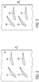
- the figures 2 and 3 show two examples of the location of the blades 43, 45 on their shell.
- a radial view of the blades 43, 45 and of the outer shell 54 is shown.
- the arrow 14 represents the general direction of the flow which is substantially axial at the outlet of the compressor.
- the rows of blades 43 and 45 do not have the same inclination with respect to the flow, in order to gradually straighten each flow and thus minimize the load or the deflection that each of the blades must ensure.
- the blades are staggered.
- the blades 45 are axially following the blades 43, the example of the figure 3 shows vanes which overlap axially. This allows a better compactness of the shell for the same flow straightening rate.
- the blades 43, 45 have an axial length, which can be identical.
- the length of the vanes 45, less inclined with respect to the flow may be the greater of the two.
- the blades overlap axially by at least 10% of the axial length of the blades 43 (identical or shorter than the blades 45).
- the overlap can be greater without however exceeding 70% of the length of the blades 43.
- the arrangement of the blades of the compressor 26 may be different from that illustrated in figure 1 .
- the compressor can comprise a row of rotor blades first, followed by a stator row, then another row of rotor blades and finally two or three rows of stator blades.
Landscapes
- Engineering & Computer Science (AREA)
- Mechanical Engineering (AREA)
- General Engineering & Computer Science (AREA)
- Chemical & Material Sciences (AREA)
- Combustion & Propulsion (AREA)
- Physics & Mathematics (AREA)
- Fluid Mechanics (AREA)
- Structures Of Non-Positive Displacement Pumps (AREA)
Abstract
Description
- L'invention concerne une turbomachine, notamment un turboréacteur d'aéronef et en particulier la structure de son compresseur basse-pression.
- Le document
US 2010/0124487 A1 décrit une turbomachine axiale avec des aubes statoriques à orientation variable (VSV pour « variable stator vane » en anglais). Dans ce document, plusieurs aubes sont fixées à une même plate-forme d'actionnement afin de simplifier le système d'actionnement des aubes à orientation variable. - Le document
US 5,911,679 A1 décrit un compresseur de turbomachine qui comprend - mis à part la toute dernière rangée d'aubes - uniquement des aubes à orientation variable. - Ces technologies ne sont pas adaptées pour des compresseurs de turbomachine à haute vitesse. En effet, la vitesse de rotation des rotors de compresseur de turbomachine impacte le rendement de la turbomachine. En minimisant le poids et le nombre d'étages du compresseur, il devient possible et souhaitable de faire tourner le compresseur à de plus hautes vitesses. Un des facteurs limitant la vitesse de rotation est la charge sur les aubes, et en particulier la charge appliquée sur les aubes du redresseur le plus aval du compresseur, c'est-à-dire celles s'étendant sur la plus courte section de la veine et où la pression est la plus forte.
- L'invention a pour objectif de résoudre au moins un des problèmes posés par l'art antérieur. Plus précisément, l'invention a pour objectif de proposer un compresseur basse-pression pour turbomachine qui soit compact et léger et qui limite les efforts sur les aubes aval. L'invention a également pour objectif de proposer une solution simple, résistante, économique, fiable, et à haut rendement.
- L'invention a pour objet une turbomachine, notamment un turboréacteur d'aéronef, comprenant premier carter définissant une première veine en col de cygne, un second carter définissant une seconde veine en col de cygne, et un compresseur basse-pression positionné directement entre la première et la seconde veine en col de cygne, le compresseur comprenant : un rotor muni d'au plus quatre rangées annulaires d'aubes rotoriques ; un redresseur muni d'au plus six, et préférentiellement au plus quatre, rangées annulaires d'aubes statoriques ; remarquable en ce qu'il peut être défini un plan géométrique en amont duquel les rangées d'aubes rotoriques et statoriques du compresseur sont entrelacées, et en aval duquel au moins deux rangées d'aubes sont prévues, les aubes du compresseur en aval du plan géométrique étant uniquement statoriques, à orientation fixe, et fixées à une virole interne commune.
- Ainsi, un plan perpendiculaire à l'axe de rotation de la turbomachine et positionné entre deux rangées d'aubes permet de délimiter le compresseur en deux sections, une section amont dans laquelle les rangées d'aubes rotoriques et statoriques alternent et une section aval dans laquelle seules des aubes statoriques sont agencées.
- Par abus de langage, il est fait mention d'un plan géométrique. En effet, selon certains modes de réalisation, lorsque la veine est très inclinée par rapport à l'axe, il est possible que les aubes de deux rangées adjacentes se chevauchent très légèrement axialement. Ainsi, le plan géométrique délimitant le compresseur en deux sections peut en fait prendre la forme d'une surface conique inter-aubes en amont de laquelle des aubes rotoriques et statoriques sont alternées, et en aval de laquelle seules des aubes statoriques sont présentes.
- L'exclusion des aubes rotoriques en amont du plan dont il s'agit ici porte uniquement sur le compresseur, les aubes d'un éventuel second compresseur en aval (haute-pression) ou les aubes de turbines n'étant pas concernées. Selon des modes avantageux de l'invention, la turbomachine peut comprendre une ou plusieurs des caractéristiques suivantes, prises isolément ou selon toutes les combinaisons techniques possibles :
- les au moins deux rangées d'aubes statoriques en aval du plan géométrique sont configurées pour redresser progressivement le flux de gaz de sorte à ce qu'il ne soit sensiblement axial qu'après avoir traversé lesdites au moins deux rangées d'aubes statoriques ;
- le compresseur comprend exactement deux rangées d'aubes rotoriques ;
- le compresseur comprend exactement trois rangées d'aubes rotoriques ;
- le compresseur comprend exactement quatre rangées d'aubes statoriques, dont au moins deux en aval du plan géométrique ;
- le compresseur comprend exactement cinq rangées d'aubes statoriques, dont au moins deux en aval du plan géométrique ;
- la première rangée d'aubes à l'amont du compresseur est une rangée d'aubes statoriques, préférentiellement à orientation variable ;
- à l'exception de la rangée d'aubes statoriques la plus amont, les aubes statoriques sont à orientation fixe ;
- les aubes statoriques des au moins deux rangées sont positionnées en quinconce sur ladite virole ;
- les aubes ont une longueur axiale et les au moins deux rangées positionnées en quinconce se chevauchent axialement deux à deux, d'au moins 10% de la longueur axiale des aubes d'une des rangées, préférentiellement d'au moins 20% ou 30% ;
- les au moins deux rangées d'aubes participent chacune partiellement au redressement du flux. Le flux en amont des au moins deux rangées et en aval des au moins deux rangées change de direction. Ce changement est pour partie dû au changement de direction infligé par chaque rangée d'aubes respectivement. Par exemple la première des au moins deux rangées redresse de au moins 40% le flux (= 40% de sa déviation totale subie entre l'amont et l'aval de ces au moins deux rangées d'aubes) et les secondes aubes ou optionnellement troisièmes aubes complémentent le redressement (c'est-à-dire au plus 60%) ;
- la longueur axiale des aubes en aval du plan géométrique est croissante d'amont en aval ;
- le compresseur est configuré pour permettre une vitesse périphérique des aubes rotoriques supérieure à 300 m/s, préférentiellement supérieure à 340 m/s ;
- la turbomachine comprend une soufflante reliée au rotor par l'intermédiaire d'un réducteur ;
- les carters comprennent des bras de supports radiaux, le flux d'air entrant dans la turbomachine rencontrant, dans cet ordre, la soufflante, les bras radiaux du premier carter, le compresseur, puis les bras radiaux du second carter ;
- le premier carter est précédé d'une rangée unique d'aubes statoriques ;
- la turbomachine comprend un bec de séparation entre un flux primaire et un flux secondaire, ladite rangée unique d'aubes statoriques étant au voisinage dudit bec ;
- la turbomachine comprend un compresseur haute-pression et en ce que le second carter relie le compresseur basse-pression au compresseur haute-pression ;
- L'invention peut également porter sur un procédé de compression d'un flux d'air au moyen d'un compresseur tel que défini ci-dessus, le procédé comprenant l'entraînement des aubes rotoriques à une vitesse périphérique supérieure à 340 m/s.
- Selon d'autres aspects de l'invention :
- le réducteur comporte un porte-satellite solidaire du stator de la turbomachine.
- le réducteur comprend un rapport de réduction compris entre 1,50 et 2,50.
- De manière générale, les modes avantageux de chaque objet de l'invention sont également applicables aux autres objets de l'invention. Chaque objet de l'invention est combinable aux autres objets, et les objets de l'invention sont également combinables aux modes de réalisation de la description, qui en plus sont combinables entre eux, selon toutes les combinaisons techniques possibles, à moins que le contraire ne soit explicitement mentionné.
- Le compresseur basse-pression selon l'invention ne comporte que 2 ou 3 étages d'aubes. Le fait de prévoir au moins deux rangées d'aubes statoriques permet de partager les efforts de redressement du flux sur ces aubes statoriques et donc d'augmenter la vitesse de rotation du rotor. Tout ceci combiné permet un haut rendement sans compromission de l'encombrement du compresseur, de son poids ou du nombre de pièces mises en jeu.
- Le faible rapport de la vitesse axiale du flux sur la vitesse de rotation du rotor impose de très fortes déviations sur les stators pour le redressement. La double rangée d'aubes statoriques permet de retrouver des conditions de charge et déviation sur ces aubes qui sont similaires à un compresseur à plus petite vitesse et plus grand nombre de rangées d'aubes.
-
- La
figure 1 représente une turbomachine axiale selon l'invention ; - La
figure 2 représente une vue radiale des aubes aval selon un premier mode de réalisation ; - La
figure 3 représente une vue radiale des aubes aval selon un second mode de réalisation. - Dans la description qui va suivre, les termes « interne » et « externe » renvoient à un positionnement par rapport à l'axe de rotation d'une turbomachine axiale. La direction axiale correspond à la direction le long de l'axe de rotation de la turbomachine. La direction radiale est perpendiculaire à l'axe de rotation. L'amont et l'aval sont en référence au sens d'écoulement principal du flux dans la turbomachine. Le terme « solidaire » est compris comme solidaire en rotation La
figure 1 représente de manière simplifiée une turbomachine axiale. Il s'agit dans ce cas précis d'un turboréacteur 2 double-flux. - La turbomachine 2 présente un axe de rotation 4 pouvant également former un axe de symétrie. La turbomachine 2 présente une entrée annulaire 6 se divisant en une veine primaire 8 et en une veine secondaire 10 grâce à un bec de séparation 12 de forme circulaire. Ces veines 8 et 10 sont empruntées par, respectivement, un flux primaire 14 et un flux secondaire 16, qui se rejoignent en sortie de la turbomachine. Les flux primaire 14 et secondaire 16 sont des flux annulaires coaxiaux et emmanchés l'un dans l'autre. Ils sont canalisés par les parois internes et externes de la turbomachine 2.
- Le flux secondaire 16 est accéléré par une soufflante 18, notamment disposée en entrée 6, si bien qu'une réaction de poussée peut être générée. Celle-ci peut être employée pour le vol d'un aéronef. Des pales de redressement 20 peuvent être disposées dans la veine secondaire 10 et être configurées afin d'augmenter la composante axiale de la vitesse du flux secondaire. La soufflante peut être disposée en amont de la veine primaire 8 et de la veine secondaire 10, notamment à distance axialement de ces veines.
- Alternativement, la soufflante peut être du type non-carénée, par exemple à double rotor contrarotatifs. Elle peut être placée autour de la veine primaire.
- La turbomachine 2 comprend une zone de compression, une chambre de combustion 22 et une zone de détente du flux primaire 14.
- La zone de compression est formée par deux compresseurs, un compresseur basse-pression 24 et un compresseur haute-pression 26. Chacun des compresseurs comprend des aubes rotoriques et des aubes statoriques formant un redresseur.
- Le compresseur haute-pression 26 peut être placé en entrée de la chambre de combustion 22.
- En aval de la chambre de combustion 22, la turbomachine 2 peut présenter une turbine haute-pression 28 couplée à un arbre haute-pression 30, puis une turbine basse-pression 32 couplée à un arbre basse-pression 34. Ce dernier peut être libre en rotation par rapport à l'arbre haute-pression 30. Ces turbines 28, 32 peuvent former la zone de détente du flux primaire 14.
- En fonctionnement, la puissance mécanique reçue des turbines 28, 32 est transmise via les arbres 30, 34 et met en mouvement les compresseurs 24, 26.
- Ces derniers comportent plusieurs rangées d'aubes de rotor associées à des rangées d'aubes de stator. Les aubes de rotor sont solidaires ou cinématiquement entraînées par les arbres 30, 34 autour de l'axe de rotation 4 pour générer un débit d'air et de comprimer progressivement ce dernier jusqu'à l'entrée de la chambre de combustion 22.
- La turbomachine peut comprendre des moyens de démultiplication, tel un réducteur 36 qui entraîne la soufflante 18 à une vitesse de rotation plus faible que celle des aubes rotoriques. Ainsi, deux turbines suffisent pour entraîner les compresseurs et la soufflante à trois vitesses de rotation différentes.
- Dans cet exemple, le compresseur basse-pression 24 comprend deux rangées d'aubes rotoriques 40, 42 solidaires de l'arbre 34 via un rotor 44.
- Le compresseur 24 comprend des aubes statoriques 39, 41 intercalées entre les aubes rotoriques 40, 42.
- Selon l'invention, le compresseur 24 comprend dans sa partie aval deux rangées successives d'aubes statoriques 43, 45. Ainsi, au-delà d'un plan P, seules des aubes statoriques sont présentes, alors qu'en amont du plan P, les aubes statoriques et rotoriques sont alternées. L'ensemble des aubes statoriques 39, 41, 43, 45 forme le redresseur 35 du compresseur 24.
- Le stator de la turbomachine 2 peut comprendre plusieurs carters support, dont un carter amont 47 et un carter aval 49 disposés de part et d'autre du compresseur 24. Ces carters 47, 49 peuvent comprendre des manches annulaires formant des tronçons de la veine primaire 8. Ils peuvent présenter des bras de support sensiblement radiaux (dits « struts » en anglais) 46, 48 traversant radialement la veine 8. Les manches annulaires peuvent présenter des profils en col de cygne. Elles peuvent marquer des réductions de diamètre de la veine primaire 8, tout comme sa convergence progressive.
- Le carter amont 47 et ses bras 46 peuvent supporter le réducteur 36.
- En amont des bras 46 peut être prévu une rangée d'aubes statoriques 37 à proximité du bec 12.
- En aval des bras 48 figure le compresseur haute-pression 26 muni d'aubes statoriques 50 et rotoriques 52. Ces dernières étant entraînées en rotation au moyen de l'arbre 30.
- Si la veine 8 peut être circonscrite entre deux surfaces formées par plusieurs viroles successives, les deux rangées d'aubes statoriques 43, 45 en aval du plan P peuvent être montées sur la même virole externe 54 et/ou interne 56.
- Les
figures 2 et 3 montrent deux exemples d'implantation des aubes 43, 45 sur leur virole. Dans cet exemple, une vue radiale des aubes 43, 45 et de la virole externe 54 est représentée. La flèche 14 représente la direction générale du flux qui est sensiblement axiale en sortie du compresseur. - Les rangées d'aubes 43 et 45 n'ont pas la même inclinaison par rapport au flux, afin de redresser chacune progressivement le flux et ainsi minimiser la charge ou la déviation que doit assurer chacune des aubes.
- Dans cet exemple, les aubes sont en quinconce.
- Si sur la
figure 2 , les aubes 45 sont axialement à la suite des aubes 43, l'exemple de lafigure 3 montre des aubes qui se superposent axialement. Ceci permet une meilleure compacité de la virole pour un même taux de redressement du flux. - Axialement, c'est-à-dire selon l'axe horizontale des
figures 2 et 3 , les aubes 43, 45 présentent une longueur axiale, qui peut être identique. Alternativement, la longueur des aubes 45, moins inclinées par rapport au flux, peut être la plus grande des deux. - Dans l'exemple de la
figure 3 , les aubes se chevauchent axialement d'au moins 10% de la longueur axiale des aubes 43 (identique ou plus courtes que les aubes 45). Le chevauchement peut être plus important sans toutefois dépasser 70% de la longueur des aubes 43. - L'arrangement des aubes du compresseur 26 peut être différent de celui illustré en
figure 1 . Notamment, le compresseur peut comprendre une rangée d'aube rotorique en premier, suivie d'une rangée statorique, puis une autre rangée rotorique et enfin deux ou trois rangées d'aubes statoriques.
Claims (15)
- Turbomachine (2), notamment turboréacteur d'aéronef, comprenant premier carter (47) définissant une première veine en col de cygne, un second carter (49) définissant une seconde veine en col de cygne, et un compresseur basse-pression (24) positionné directement entre la première et la seconde veine en col de cygne, caractérisée en ce que le compresseur comprend :- un rotor (44) muni d'au plus quatre rangées annulaires d'aubes rotoriques (40, 42) ;- un redresseur (35) muni d'au plus six, et préférentiellement d'au plus quatre, rangées annulaires d'aubes statoriques (39, 41, 43, 45) ;turbomachine dans laquelle il peut être défini un plan géométrique (P) en amont duquel les rangées d'aubes rotoriques (40, 42) et statoriques (39, 41) du compresseur (24) sont entrelacées, et en aval duquel au moins deux rangées (43, 45) d'aubes sont prévues, les aubes (43, 45) du compresseur (24) en aval du plan géométrique (P) étant uniquement statoriques, à orientation fixe, et fixées à une virole interne commune (56).
- Turbomachine selon la revendication 1, caractérisée en ce que les au moins deux rangées d'aubes statoriques (43, 45) en aval du plan géométrique (P) sont configurées pour redresser progressivement le flux (14) de gaz de sorte à ce qu'il ne soit sensiblement axial qu'après avoir traversé lesdites au moins deux rangées d'aubes statoriques (43, 45).
- Turbomachine selon l'une des revendications 1 ou 2, caractérisée en ce que les au moins deux rangées d'aubes (43, 45) participent chacune partiellement au redressement du flux (14), la première des au moins deux rangées (43, 45) déviant le flux d'au moins 40% de sa déviation totale subie entre l'amont et l'aval de ces au moins deux rangées d'aubes (43, 45).
- Turbomachine selon l'une des revendications 1 à 3, caractérisée en ce que le compresseur (24) comprend exactement deux rangées d'aubes rotoriques (40, 42).
- Turbomachine selon l'une des revendications 1 à 4, caractérisée en ce que le compresseur (24) comprend exactement quatre rangées d'aubes statoriques (39, 41, 43, 45), dont au moins deux (43, 45) en aval du plan géométrique (P).
- Turbomachine selon l'une des revendications 1 à 5, caractérisée en ce que la première rangée d'aubes à l'amont du compresseur (24) est une rangée d'aubes statoriques (39), préférentiellement à orientation variable.
- Turbomachine selon l'une des revendications 1 à 6, caractérisée en ce qu'à l'exception de la rangée d'aubes statoriques (39) la plus amont, les aubes statoriques (41, 43, 45) sont à orientation fixe.
- Turbomachine selon l'une des revendications 1 à 7, caractérisée en ce que les aubes statoriques (43, 45) des au moins deux rangées sont positionnées en quinconce sur ladite virole (54, 56).
- Turbomachine selon la revendication 8, caractérisée en ce que les aubes ont une longueur axiale et les au moins deux rangées positionnées en quinconce se chevauchent axialement deux à deux, d'au moins 10% de la longueur axiale des aubes d'une des rangées, préférentiellement d'au moins 20% ou 30%.
- Turbomachine selon l'une des revendications 1 à 9, caractérisée en ce que la longueur axiale des aubes (43, 45) en aval du plan géométrique (P) est croissante d'amont en aval.
- Turbomachine selon l'une des revendications 1 à 10, caractérisée en ce que le compresseur (24) est configuré pour permettre une vitesse périphérique des aubes rotoriques (40, 42) supérieure à 300 m/s, préférentiellement supérieure à 340 m/s.
- Turbomachine selon l'une des revendications 1 à 11, caractérisée en ce qu'elle comprend une soufflante (18) reliée au rotor (44) par l'intermédiaire d'un réducteur (36) et en ce que les carters (47, 49) comprennent des bras de supports radiaux (46, 48), le flux d'air entrant dans la turbomachine rencontrant, dans cet ordre, la soufflante (18), les bras radiaux (46) du premier carter (47), le compresseur (24), puis les bras radiaux (48) du second carter (49).
- Turbomachine selon l'une des revendications 1 à 12, caractérisée en ce que le premier carter (47) est précédé d'une rangée unique d'aubes statoriques (37).
- Turbomachine selon la revendication 13, caractérisée en ce qu'elle comprend un bec de séparation (12) entre un flux primaire (14) et un flux secondaire (16), ladite rangée unique d'aubes statoriques (37) étant au voisinage dudit bec (12).
- Turbomachine selon l'une des revendications 1 à 14, caractérisée en ce qu'elle comprend un compresseur haute-pression (26) et en ce que le second carter (49) relie le compresseur basse-pression (24) au compresseur haute-pression (26).
Applications Claiming Priority (1)
| Application Number | Priority Date | Filing Date | Title |
|---|---|---|---|
| BE20185481A BE1026455B1 (fr) | 2018-07-09 | 2018-07-09 | Compresseur de turbomachine |
Publications (2)
| Publication Number | Publication Date |
|---|---|
| EP3594503A1 true EP3594503A1 (fr) | 2020-01-15 |
| EP3594503B1 EP3594503B1 (fr) | 2021-06-30 |
Family
ID=63047080
Family Applications (1)
| Application Number | Title | Priority Date | Filing Date |
|---|---|---|---|
| EP19183977.8A Active EP3594503B1 (fr) | 2018-07-09 | 2019-07-02 | Turbomachine |
Country Status (3)
| Country | Link |
|---|---|
| EP (1) | EP3594503B1 (fr) |
| CN (1) | CN110700891A (fr) |
| BE (1) | BE1026455B1 (fr) |
Cited By (2)
| Publication number | Priority date | Publication date | Assignee | Title |
|---|---|---|---|---|
| WO2025036664A1 (fr) * | 2023-08-17 | 2025-02-20 | IFP Energies Nouvelles | Stator pour pompe comprenant des pales principales et des pales secondaires |
| US12497906B2 (en) * | 2022-04-05 | 2025-12-16 | Safran Aero Boosters | Tandem stator |
Families Citing this family (2)
| Publication number | Priority date | Publication date | Assignee | Title |
|---|---|---|---|---|
| BE1028108B1 (fr) * | 2020-02-28 | 2021-09-28 | Safran Aero Boosters | Compresseur transsonique de turbomachine |
| GB2632547A (en) * | 2023-07-07 | 2025-02-12 | Honeywell Int Inc | Gas turbine engines comprising pitched nose splitter structures and aircraft comprising the same |
Citations (5)
| Publication number | Priority date | Publication date | Assignee | Title |
|---|---|---|---|---|
| US5911679A (en) | 1996-12-31 | 1999-06-15 | General Electric Company | Variable pitch rotor assembly for a gas turbine engine inlet |
| EP1308601A1 (fr) * | 2001-10-31 | 2003-05-07 | Snecma Moteurs | Dispositif de décharge dans un turboréacteur à double flux |
| US20080098715A1 (en) * | 2006-10-31 | 2008-05-01 | Robert Joseph Orlando | Turbofan engine assembly and method of assembling same |
| US20100124487A1 (en) | 2008-11-19 | 2010-05-20 | Rolls-Royce Deutschland Ltd & Co Kg | Multi-vane variable stator unit of a fluid flow machine |
| EP2921716A1 (fr) * | 2014-03-20 | 2015-09-23 | Rolls-Royce Deutschland Ltd & Co KG | Groupe de série d'aubes |
Family Cites Families (6)
| Publication number | Priority date | Publication date | Assignee | Title |
|---|---|---|---|---|
| FR2083742A5 (fr) * | 1970-03-23 | 1971-12-17 | Cit Alcatel | |
| EP2450531B1 (fr) * | 2010-11-04 | 2013-05-15 | Siemens Aktiengesellschaft | Refroidissement d'une compresseur axial |
| US9068460B2 (en) * | 2012-03-30 | 2015-06-30 | United Technologies Corporation | Integrated inlet vane and strut |
| JP6185783B2 (ja) * | 2013-07-29 | 2017-08-23 | 三菱日立パワーシステムズ株式会社 | 軸流圧縮機、軸流圧縮機を備えたガスタービンおよび軸流圧縮機の改造方法 |
| BE1024024B1 (fr) * | 2014-10-09 | 2017-10-30 | Safran Aero Boosters S.A. | Compresseur de turbomachine axiale avec rotor contrarotatif |
| FR3046201B1 (fr) * | 2015-12-24 | 2018-01-19 | Safran Aircraft Engines | Turboreacteur avec un moyen de reprise de poussee sur le carter inter-compresseurs |
-
2018
- 2018-07-09 BE BE20185481A patent/BE1026455B1/fr active IP Right Grant
-
2019
- 2019-07-02 EP EP19183977.8A patent/EP3594503B1/fr active Active
- 2019-07-09 CN CN201910613590.8A patent/CN110700891A/zh active Pending
Patent Citations (5)
| Publication number | Priority date | Publication date | Assignee | Title |
|---|---|---|---|---|
| US5911679A (en) | 1996-12-31 | 1999-06-15 | General Electric Company | Variable pitch rotor assembly for a gas turbine engine inlet |
| EP1308601A1 (fr) * | 2001-10-31 | 2003-05-07 | Snecma Moteurs | Dispositif de décharge dans un turboréacteur à double flux |
| US20080098715A1 (en) * | 2006-10-31 | 2008-05-01 | Robert Joseph Orlando | Turbofan engine assembly and method of assembling same |
| US20100124487A1 (en) | 2008-11-19 | 2010-05-20 | Rolls-Royce Deutschland Ltd & Co Kg | Multi-vane variable stator unit of a fluid flow machine |
| EP2921716A1 (fr) * | 2014-03-20 | 2015-09-23 | Rolls-Royce Deutschland Ltd & Co KG | Groupe de série d'aubes |
Cited By (3)
| Publication number | Priority date | Publication date | Assignee | Title |
|---|---|---|---|---|
| US12497906B2 (en) * | 2022-04-05 | 2025-12-16 | Safran Aero Boosters | Tandem stator |
| WO2025036664A1 (fr) * | 2023-08-17 | 2025-02-20 | IFP Energies Nouvelles | Stator pour pompe comprenant des pales principales et des pales secondaires |
| FR3152171A1 (fr) * | 2023-08-17 | 2025-02-21 | IFP Energies Nouvelles | Stator pour pompe comprenant des pales principales et des pales secondaires |
Also Published As
| Publication number | Publication date |
|---|---|
| BE1026455B1 (fr) | 2020-02-03 |
| BE1026455A1 (fr) | 2020-01-30 |
| EP3594503B1 (fr) | 2021-06-30 |
| CN110700891A (zh) | 2020-01-17 |
Similar Documents
| Publication | Publication Date | Title |
|---|---|---|
| EP3204620B1 (fr) | Stator de turbomachine d'aéronef | |
| EP1956191B1 (fr) | Turbine à gaz à turbines HP et BP contra-rotatives | |
| EP3594503B1 (fr) | Turbomachine | |
| WO2019243558A1 (fr) | Turboréacteur à transmission hybride | |
| WO2019043330A1 (fr) | Aube de redresseur de soufflante de turbomachine, ensemble de turbomachine comprenant une telle aube et turbomachine equipee de ladite aube ou dudit ensemble | |
| EP3927945B1 (fr) | Roue de stator d'une turbomachine comprenant des aubes présentant des cordes différentes | |
| EP4073369A1 (fr) | Système propulsif aéronautique à rendement propulsif amélioré | |
| EP3412876B1 (fr) | Compresseur a géométrie variable de turbomachine axiale | |
| EP3299605B1 (fr) | Carter avec bras aspirant pour turbomachine axiale | |
| BE1028108B1 (fr) | Compresseur transsonique de turbomachine | |
| EP4077880A1 (fr) | Module pour turbomachine | |
| EP3290657B1 (fr) | Stator à aubes ajustables pour compresseur de turbomachine axiale | |
| EP3569854B1 (fr) | Architecture de turbomachine a triple compresseur | |
| FR3131600A1 (fr) | Ensemble propulsif pour un aéronef | |
| BE1027469B1 (fr) | Architecture de turbomachine avec booster accéléré | |
| WO2017187093A1 (fr) | Ensemble de redressement de flux d'air et turbomachine comprenant un tel ensemble | |
| BE1032247B1 (fr) | Ensemble statorique de turbomachine comportant des rangées d'aubes en tandem | |
| FR3104644A1 (fr) | Système propulsif aéronautique à rendement propulsif amélioré | |
| WO2024121463A1 (fr) | Ensemble propulsif pour un aéronef | |
| FR3135747A1 (fr) | Ensemble propulsif pour un aeronef | |
| EP4274949A1 (fr) | Ensemble de redressement | |
| CA3130189A1 (fr) | Redresseur de flux secondaire a tuyere integree |
Legal Events
| Date | Code | Title | Description |
|---|---|---|---|
| PUAI | Public reference made under article 153(3) epc to a published international application that has entered the european phase |
Free format text: ORIGINAL CODE: 0009012 |
|
| STAA | Information on the status of an ep patent application or granted ep patent |
Free format text: STATUS: THE APPLICATION HAS BEEN PUBLISHED |
|
| AK | Designated contracting states |
Kind code of ref document: A1 Designated state(s): AL AT BE BG CH CY CZ DE DK EE ES FI FR GB GR HR HU IE IS IT LI LT LU LV MC MK MT NL NO PL PT RO RS SE SI SK SM TR |
|
| AX | Request for extension of the european patent |
Extension state: BA ME |
|
| STAA | Information on the status of an ep patent application or granted ep patent |
Free format text: STATUS: REQUEST FOR EXAMINATION WAS MADE |
|
| 17P | Request for examination filed |
Effective date: 20200414 |
|
| RBV | Designated contracting states (corrected) |
Designated state(s): AL AT BE BG CH CY CZ DE DK EE ES FI FR GB GR HR HU IE IS IT LI LT LU LV MC MK MT NL NO PL PT RO RS SE SI SK SM TR |
|
| GRAP | Despatch of communication of intention to grant a patent |
Free format text: ORIGINAL CODE: EPIDOSNIGR1 |
|
| STAA | Information on the status of an ep patent application or granted ep patent |
Free format text: STATUS: GRANT OF PATENT IS INTENDED |
|
| INTG | Intention to grant announced |
Effective date: 20210113 |
|
| GRAS | Grant fee paid |
Free format text: ORIGINAL CODE: EPIDOSNIGR3 |
|
| GRAA | (expected) grant |
Free format text: ORIGINAL CODE: 0009210 |
|
| STAA | Information on the status of an ep patent application or granted ep patent |
Free format text: STATUS: THE PATENT HAS BEEN GRANTED |
|
| AK | Designated contracting states |
Kind code of ref document: B1 Designated state(s): AL AT BE BG CH CY CZ DE DK EE ES FI FR GB GR HR HU IE IS IT LI LT LU LV MC MK MT NL NO PL PT RO RS SE SI SK SM TR |
|
| REG | Reference to a national code |
Ref country code: CH Ref legal event code: EP |
|
| REG | Reference to a national code |
Ref country code: DE Ref legal event code: R096 Ref document number: 602019005700 Country of ref document: DE Ref country code: AT Ref legal event code: REF Ref document number: 1406594 Country of ref document: AT Kind code of ref document: T Effective date: 20210715 |
|
| REG | Reference to a national code |
Ref country code: IE Ref legal event code: FG4D Free format text: LANGUAGE OF EP DOCUMENT: FRENCH |
|
| REG | Reference to a national code |
Ref country code: LT Ref legal event code: MG9D |
|
| PG25 | Lapsed in a contracting state [announced via postgrant information from national office to epo] |
Ref country code: FI Free format text: LAPSE BECAUSE OF FAILURE TO SUBMIT A TRANSLATION OF THE DESCRIPTION OR TO PAY THE FEE WITHIN THE PRESCRIBED TIME-LIMIT Effective date: 20210630 Ref country code: HR Free format text: LAPSE BECAUSE OF FAILURE TO SUBMIT A TRANSLATION OF THE DESCRIPTION OR TO PAY THE FEE WITHIN THE PRESCRIBED TIME-LIMIT Effective date: 20210630 Ref country code: BG Free format text: LAPSE BECAUSE OF FAILURE TO SUBMIT A TRANSLATION OF THE DESCRIPTION OR TO PAY THE FEE WITHIN THE PRESCRIBED TIME-LIMIT Effective date: 20210930 |
|
| REG | Reference to a national code |
Ref country code: NL Ref legal event code: MP Effective date: 20210630 |
|
| REG | Reference to a national code |
Ref country code: AT Ref legal event code: MK05 Ref document number: 1406594 Country of ref document: AT Kind code of ref document: T Effective date: 20210630 |
|
| PG25 | Lapsed in a contracting state [announced via postgrant information from national office to epo] |
Ref country code: SE Free format text: LAPSE BECAUSE OF FAILURE TO SUBMIT A TRANSLATION OF THE DESCRIPTION OR TO PAY THE FEE WITHIN THE PRESCRIBED TIME-LIMIT Effective date: 20210630 Ref country code: RS Free format text: LAPSE BECAUSE OF FAILURE TO SUBMIT A TRANSLATION OF THE DESCRIPTION OR TO PAY THE FEE WITHIN THE PRESCRIBED TIME-LIMIT Effective date: 20210630 Ref country code: LV Free format text: LAPSE BECAUSE OF FAILURE TO SUBMIT A TRANSLATION OF THE DESCRIPTION OR TO PAY THE FEE WITHIN THE PRESCRIBED TIME-LIMIT Effective date: 20210630 Ref country code: NO Free format text: LAPSE BECAUSE OF FAILURE TO SUBMIT A TRANSLATION OF THE DESCRIPTION OR TO PAY THE FEE WITHIN THE PRESCRIBED TIME-LIMIT Effective date: 20210930 Ref country code: GR Free format text: LAPSE BECAUSE OF FAILURE TO SUBMIT A TRANSLATION OF THE DESCRIPTION OR TO PAY THE FEE WITHIN THE PRESCRIBED TIME-LIMIT Effective date: 20211001 |
|
| PG25 | Lapsed in a contracting state [announced via postgrant information from national office to epo] |
Ref country code: CZ Free format text: LAPSE BECAUSE OF FAILURE TO SUBMIT A TRANSLATION OF THE DESCRIPTION OR TO PAY THE FEE WITHIN THE PRESCRIBED TIME-LIMIT Effective date: 20210630 Ref country code: AT Free format text: LAPSE BECAUSE OF FAILURE TO SUBMIT A TRANSLATION OF THE DESCRIPTION OR TO PAY THE FEE WITHIN THE PRESCRIBED TIME-LIMIT Effective date: 20210630 Ref country code: PT Free format text: LAPSE BECAUSE OF FAILURE TO SUBMIT A TRANSLATION OF THE DESCRIPTION OR TO PAY THE FEE WITHIN THE PRESCRIBED TIME-LIMIT Effective date: 20211102 Ref country code: NL Free format text: LAPSE BECAUSE OF FAILURE TO SUBMIT A TRANSLATION OF THE DESCRIPTION OR TO PAY THE FEE WITHIN THE PRESCRIBED TIME-LIMIT Effective date: 20210630 Ref country code: RO Free format text: LAPSE BECAUSE OF FAILURE TO SUBMIT A TRANSLATION OF THE DESCRIPTION OR TO PAY THE FEE WITHIN THE PRESCRIBED TIME-LIMIT Effective date: 20210630 Ref country code: SM Free format text: LAPSE BECAUSE OF FAILURE TO SUBMIT A TRANSLATION OF THE DESCRIPTION OR TO PAY THE FEE WITHIN THE PRESCRIBED TIME-LIMIT Effective date: 20210630 Ref country code: SK Free format text: LAPSE BECAUSE OF FAILURE TO SUBMIT A TRANSLATION OF THE DESCRIPTION OR TO PAY THE FEE WITHIN THE PRESCRIBED TIME-LIMIT Effective date: 20210630 Ref country code: EE Free format text: LAPSE BECAUSE OF FAILURE TO SUBMIT A TRANSLATION OF THE DESCRIPTION OR TO PAY THE FEE WITHIN THE PRESCRIBED TIME-LIMIT Effective date: 20210630 Ref country code: ES Free format text: LAPSE BECAUSE OF FAILURE TO SUBMIT A TRANSLATION OF THE DESCRIPTION OR TO PAY THE FEE WITHIN THE PRESCRIBED TIME-LIMIT Effective date: 20210630 |
|
| PG25 | Lapsed in a contracting state [announced via postgrant information from national office to epo] |
Ref country code: PL Free format text: LAPSE BECAUSE OF FAILURE TO SUBMIT A TRANSLATION OF THE DESCRIPTION OR TO PAY THE FEE WITHIN THE PRESCRIBED TIME-LIMIT Effective date: 20210630 |
|
| REG | Reference to a national code |
Ref country code: DE Ref legal event code: R097 Ref document number: 602019005700 Country of ref document: DE |
|
| PG25 | Lapsed in a contracting state [announced via postgrant information from national office to epo] |
Ref country code: MC Free format text: LAPSE BECAUSE OF FAILURE TO SUBMIT A TRANSLATION OF THE DESCRIPTION OR TO PAY THE FEE WITHIN THE PRESCRIBED TIME-LIMIT Effective date: 20210630 |
|
| PG25 | Lapsed in a contracting state [announced via postgrant information from national office to epo] |
Ref country code: DK Free format text: LAPSE BECAUSE OF FAILURE TO SUBMIT A TRANSLATION OF THE DESCRIPTION OR TO PAY THE FEE WITHIN THE PRESCRIBED TIME-LIMIT Effective date: 20210630 |
|
| PLBE | No opposition filed within time limit |
Free format text: ORIGINAL CODE: 0009261 |
|
| STAA | Information on the status of an ep patent application or granted ep patent |
Free format text: STATUS: NO OPPOSITION FILED WITHIN TIME LIMIT |
|
| PG25 | Lapsed in a contracting state [announced via postgrant information from national office to epo] |
Ref country code: LU Free format text: LAPSE BECAUSE OF NON-PAYMENT OF DUE FEES Effective date: 20210702 Ref country code: AL Free format text: LAPSE BECAUSE OF FAILURE TO SUBMIT A TRANSLATION OF THE DESCRIPTION OR TO PAY THE FEE WITHIN THE PRESCRIBED TIME-LIMIT Effective date: 20210630 |
|
| 26N | No opposition filed |
Effective date: 20220331 |
|
| PG25 | Lapsed in a contracting state [announced via postgrant information from national office to epo] |
Ref country code: IT Free format text: LAPSE BECAUSE OF FAILURE TO SUBMIT A TRANSLATION OF THE DESCRIPTION OR TO PAY THE FEE WITHIN THE PRESCRIBED TIME-LIMIT Effective date: 20210630 Ref country code: IE Free format text: LAPSE BECAUSE OF NON-PAYMENT OF DUE FEES Effective date: 20210702 |
|
| REG | Reference to a national code |
Ref country code: CH Ref legal event code: PL |
|
| PG25 | Lapsed in a contracting state [announced via postgrant information from national office to epo] |
Ref country code: LT Free format text: LAPSE BECAUSE OF FAILURE TO SUBMIT A TRANSLATION OF THE DESCRIPTION OR TO PAY THE FEE WITHIN THE PRESCRIBED TIME-LIMIT Effective date: 20210630 Ref country code: LI Free format text: LAPSE BECAUSE OF NON-PAYMENT OF DUE FEES Effective date: 20220731 Ref country code: CH Free format text: LAPSE BECAUSE OF NON-PAYMENT OF DUE FEES Effective date: 20220731 |
|
| PG25 | Lapsed in a contracting state [announced via postgrant information from national office to epo] |
Ref country code: CY Free format text: LAPSE BECAUSE OF FAILURE TO SUBMIT A TRANSLATION OF THE DESCRIPTION OR TO PAY THE FEE WITHIN THE PRESCRIBED TIME-LIMIT Effective date: 20210630 |
|
| PG25 | Lapsed in a contracting state [announced via postgrant information from national office to epo] |
Ref country code: HU Free format text: LAPSE BECAUSE OF FAILURE TO SUBMIT A TRANSLATION OF THE DESCRIPTION OR TO PAY THE FEE WITHIN THE PRESCRIBED TIME-LIMIT; INVALID AB INITIO Effective date: 20190702 |
|
| PG25 | Lapsed in a contracting state [announced via postgrant information from national office to epo] |
Ref country code: MK Free format text: LAPSE BECAUSE OF FAILURE TO SUBMIT A TRANSLATION OF THE DESCRIPTION OR TO PAY THE FEE WITHIN THE PRESCRIBED TIME-LIMIT Effective date: 20210630 |
|
| PG25 | Lapsed in a contracting state [announced via postgrant information from national office to epo] |
Ref country code: TR Free format text: LAPSE BECAUSE OF FAILURE TO SUBMIT A TRANSLATION OF THE DESCRIPTION OR TO PAY THE FEE WITHIN THE PRESCRIBED TIME-LIMIT Effective date: 20210630 |
|
| PG25 | Lapsed in a contracting state [announced via postgrant information from national office to epo] |
Ref country code: MT Free format text: LAPSE BECAUSE OF FAILURE TO SUBMIT A TRANSLATION OF THE DESCRIPTION OR TO PAY THE FEE WITHIN THE PRESCRIBED TIME-LIMIT Effective date: 20210630 |
|
| PGFP | Annual fee paid to national office [announced via postgrant information from national office to epo] |
Ref country code: DE Payment date: 20250722 Year of fee payment: 7 |
|
| PGFP | Annual fee paid to national office [announced via postgrant information from national office to epo] |
Ref country code: BE Payment date: 20250722 Year of fee payment: 7 Ref country code: GB Payment date: 20250724 Year of fee payment: 7 |
|
| PGFP | Annual fee paid to national office [announced via postgrant information from national office to epo] |
Ref country code: FR Payment date: 20250722 Year of fee payment: 7 |