EP3594471A1 - Air intake structure for internal combustion engine - Google Patents
Air intake structure for internal combustion engine Download PDFInfo
- Publication number
- EP3594471A1 EP3594471A1 EP18763803.6A EP18763803A EP3594471A1 EP 3594471 A1 EP3594471 A1 EP 3594471A1 EP 18763803 A EP18763803 A EP 18763803A EP 3594471 A1 EP3594471 A1 EP 3594471A1
- Authority
- EP
- European Patent Office
- Prior art keywords
- intake
- passageway
- valve
- tumble
- downstream
- Prior art date
- Legal status (The legal status is an assumption and is not a legal conclusion. Google has not performed a legal analysis and makes no representation as to the accuracy of the status listed.)
- Granted
Links
- 238000002485 combustion reaction Methods 0.000 title claims abstract description 84
- 238000005192 partition Methods 0.000 claims abstract description 16
- 238000011144 upstream manufacturing Methods 0.000 claims abstract description 15
- 239000012530 fluid Substances 0.000 claims abstract description 7
- 239000000446 fuel Substances 0.000 description 13
- 230000005540 biological transmission Effects 0.000 description 6
- 239000003638 chemical reducing agent Substances 0.000 description 5
- 239000000203 mixture Substances 0.000 description 4
- 230000000694 effects Effects 0.000 description 3
- 239000002828 fuel tank Substances 0.000 description 3
- 230000004941 influx Effects 0.000 description 3
- 238000002347 injection Methods 0.000 description 3
- 239000007924 injection Substances 0.000 description 3
- 230000014509 gene expression Effects 0.000 description 1
- 230000005484 gravity Effects 0.000 description 1
- 239000012212 insulator Substances 0.000 description 1
- 230000013011 mating Effects 0.000 description 1
- 238000012986 modification Methods 0.000 description 1
- 230000004048 modification Effects 0.000 description 1
Images


Classifications
-
- F—MECHANICAL ENGINEERING; LIGHTING; HEATING; WEAPONS; BLASTING
- F02—COMBUSTION ENGINES; HOT-GAS OR COMBUSTION-PRODUCT ENGINE PLANTS
- F02B—INTERNAL-COMBUSTION PISTON ENGINES; COMBUSTION ENGINES IN GENERAL
- F02B31/00—Modifying induction systems for imparting a rotation to the charge in the cylinder
- F02B31/04—Modifying induction systems for imparting a rotation to the charge in the cylinder by means within the induction channel, e.g. deflectors
- F02B31/06—Movable means, e.g. butterfly valves
- F02B31/08—Movable means, e.g. butterfly valves having multiple air inlets, i.e. having main and auxiliary intake passages
-
- F—MECHANICAL ENGINEERING; LIGHTING; HEATING; WEAPONS; BLASTING
- F02—COMBUSTION ENGINES; HOT-GAS OR COMBUSTION-PRODUCT ENGINE PLANTS
- F02D—CONTROLLING COMBUSTION ENGINES
- F02D9/00—Controlling engines by throttling air or fuel-and-air induction conduits or exhaust conduits
- F02D9/08—Throttle valves specially adapted therefor; Arrangements of such valves in conduits
- F02D9/10—Throttle valves specially adapted therefor; Arrangements of such valves in conduits having pivotally-mounted flaps
- F02D9/1035—Details of the valve housing
- F02D9/1055—Details of the valve housing having a fluid by-pass
-
- F—MECHANICAL ENGINEERING; LIGHTING; HEATING; WEAPONS; BLASTING
- F02—COMBUSTION ENGINES; HOT-GAS OR COMBUSTION-PRODUCT ENGINE PLANTS
- F02M—SUPPLYING COMBUSTION ENGINES IN GENERAL WITH COMBUSTIBLE MIXTURES OR CONSTITUENTS THEREOF
- F02M35/00—Combustion-air cleaners, air intakes, intake silencers, or induction systems specially adapted for, or arranged on, internal-combustion engines
- F02M35/10—Air intakes; Induction systems
- F02M35/10006—Air intakes; Induction systems characterised by the position of elements of the air intake system in direction of the air intake flow, i.e. between ambient air inlet and supply to the combustion chamber
- F02M35/10078—Connections of intake systems to the engine
- F02M35/10085—Connections of intake systems to the engine having a connecting piece, e.g. a flange, between the engine and the air intake being foreseen with a throttle valve, fuel injector, mixture ducts or the like
-
- F—MECHANICAL ENGINEERING; LIGHTING; HEATING; WEAPONS; BLASTING
- F02—COMBUSTION ENGINES; HOT-GAS OR COMBUSTION-PRODUCT ENGINE PLANTS
- F02M—SUPPLYING COMBUSTION ENGINES IN GENERAL WITH COMBUSTIBLE MIXTURES OR CONSTITUENTS THEREOF
- F02M35/00—Combustion-air cleaners, air intakes, intake silencers, or induction systems specially adapted for, or arranged on, internal-combustion engines
- F02M35/10—Air intakes; Induction systems
- F02M35/10242—Devices or means connected to or integrated into air intakes; Air intakes combined with other engine or vehicle parts
- F02M35/10255—Arrangements of valves; Multi-way valves
-
- F—MECHANICAL ENGINEERING; LIGHTING; HEATING; WEAPONS; BLASTING
- F02—COMBUSTION ENGINES; HOT-GAS OR COMBUSTION-PRODUCT ENGINE PLANTS
- F02M—SUPPLYING COMBUSTION ENGINES IN GENERAL WITH COMBUSTIBLE MIXTURES OR CONSTITUENTS THEREOF
- F02M35/00—Combustion-air cleaners, air intakes, intake silencers, or induction systems specially adapted for, or arranged on, internal-combustion engines
- F02M35/10—Air intakes; Induction systems
- F02M35/10242—Devices or means connected to or integrated into air intakes; Air intakes combined with other engine or vehicle parts
- F02M35/10262—Flow guides, obstructions, deflectors or the like
-
- F—MECHANICAL ENGINEERING; LIGHTING; HEATING; WEAPONS; BLASTING
- F02—COMBUSTION ENGINES; HOT-GAS OR COMBUSTION-PRODUCT ENGINE PLANTS
- F02M—SUPPLYING COMBUSTION ENGINES IN GENERAL WITH COMBUSTIBLE MIXTURES OR CONSTITUENTS THEREOF
- F02M35/00—Combustion-air cleaners, air intakes, intake silencers, or induction systems specially adapted for, or arranged on, internal-combustion engines
- F02M35/10—Air intakes; Induction systems
- F02M35/104—Intake manifolds
- F02M35/108—Intake manifolds with primary and secondary intake passages
-
- F—MECHANICAL ENGINEERING; LIGHTING; HEATING; WEAPONS; BLASTING
- F02—COMBUSTION ENGINES; HOT-GAS OR COMBUSTION-PRODUCT ENGINE PLANTS
- F02M—SUPPLYING COMBUSTION ENGINES IN GENERAL WITH COMBUSTIBLE MIXTURES OR CONSTITUENTS THEREOF
- F02M69/00—Low-pressure fuel-injection apparatus ; Apparatus with both continuous and intermittent injection; Apparatus injecting different types of fuel
- F02M69/30—Low-pressure fuel-injection apparatus ; Apparatus with both continuous and intermittent injection; Apparatus injecting different types of fuel characterised by means for facilitating the starting-up or idling of engines or by means for enriching fuel charge, e.g. below operational temperatures or upon high power demand of engines
- F02M69/32—Low-pressure fuel-injection apparatus ; Apparatus with both continuous and intermittent injection; Apparatus injecting different types of fuel characterised by means for facilitating the starting-up or idling of engines or by means for enriching fuel charge, e.g. below operational temperatures or upon high power demand of engines with an air by-pass around the air throttle valve or with an auxiliary air passage, e.g. with a variably controlled valve therein
-
- Y—GENERAL TAGGING OF NEW TECHNOLOGICAL DEVELOPMENTS; GENERAL TAGGING OF CROSS-SECTIONAL TECHNOLOGIES SPANNING OVER SEVERAL SECTIONS OF THE IPC; TECHNICAL SUBJECTS COVERED BY FORMER USPC CROSS-REFERENCE ART COLLECTIONS [XRACs] AND DIGESTS
- Y02—TECHNOLOGIES OR APPLICATIONS FOR MITIGATION OR ADAPTATION AGAINST CLIMATE CHANGE
- Y02T—CLIMATE CHANGE MITIGATION TECHNOLOGIES RELATED TO TRANSPORTATION
- Y02T10/00—Road transport of goods or passengers
- Y02T10/10—Internal combustion engine [ICE] based vehicles
- Y02T10/12—Improving ICE efficiencies
Definitions
- the present invention relates to an intake structure for internal combustion engines which includes an idling air passageway, a throttle valve, and a tumble valve.
- Patent document 1 discloses an intake structure for internal combustion engines that has a throttle valve and a tumble control valve (TCV) disposed downstream of the throttle valve, and an intake passageway disposed downstream of the tumble control valve (hereinafter referred to simply as "tumble valve”) and including a main passageway defined in its lower side and an auxiliary passageway defined in its upper side for producing a tumbling flow, in which the tumble valve limits the rate of intake air into the main passageway thereby to produce a tumbling flow.
- TCV tumble control valve
- tumble valve intake passageway disposed downstream of the tumble control valve
- Patent document 2 discloses a structure having an intake passageway in a throttle body that includes a main passageway defined in its lower side and an auxiliary passageway defined in its upper side for producing a tumbling flow, and an idling air passageway defined in an upper side of the auxiliary passageway, in which while the internal combustion engine is idling with a throttle valve fully closed or is operating under a low load, idling air controlled by an idling air control valve (IACV) disposed in the idling air passageway flows from the idling air passageway into the auxiliary passageway and is supplied to a combustion chamber.
- IACV idling air control valve
- the intake passageway downstream of the tumble valve is divided into upper and lower regions by a partition plate in the intake structure for internal combustion engines that has the throttle valve and the tumble valve
- a fuel injection valve is generally disposed in an upper side of the intake passageway
- the upper region provide a main passageway having a larger channel cross section
- the lower region provide an auxiliary passageway for producing a tumbling flow in order to keep the fuel injection valve and the partition plate spaced apart by a distance for avoiding interference between injected fuel and the partition plate.
- the auxiliary passageway is defined in the lower side of the intake passageway and the idling air passageway with the idling air control valve disposed therein is disposed in the side of the auxiliary passageway, the idling air passageway is disposed in the lower side of the auxiliary passageway. Then, fuel whose specific gravity is larger than air tends to accumulate as a gas in the idling air passageway disposed in the lower side of the auxiliary passageway.
- the present invention has been made in view of the above conventional art. It is a task of the present invention to provide an intake structure for internal combustion engines that has a throttle valve and a tumble valve disposed downstream of the throttle valve, and an intake passageway disposed downstream of the tumble valve and including a main passageway defined in its upper side and an auxiliary passageway that serves as a tumbling flow channel defined in its lower side, in which a tumbling flow can easily be intensified even when the internal combustion engine is operating in an idling mode, etc.
- an intake structure for an internal combustion engine in which the internal combustion engine having a combustion chamber includes a cylinder block and a cylinder head, the cylinder head having an intake port and an exhaust port defined therein, an inlet pipe is connected to the intake port, defining a continuous intake passageway, a throttle body having an intake channel continuing to the intake passageway is connected to an upstream side of the inlet pipe with respect to an intake flow therein, the throttle body is provided with a throttle valve and a tumble valve disposed downstream thereof with respect to a flow direction of the intake flow in the intake channel, and the intake passageway is divided by a partition plate downstream of the tumble valve into an upper main passageway and a lower auxiliary passageway serving as a tumbling flow channel for producing a tumbling flow in the combustion chamber; in which an idling air passageway is defined in an upper side of the intake channel to provide fluid communication between a region upstream of the throttle valve and a region downstream of the throttle valve, the
- idling air flowing from the idling air passageway defined in the upper side of the intake channel in the throttle body into the intake channel is restrained by the tumble valve plate of the tumble valve from flowing into the upper main passageway in the intake passageway and is guided from the recess in the tumble valve plate to the lower auxiliary passageway as the tumbling flow channel. It is thus easy to produce a tumbling flow and intensify the tumbling flow.
- the idling air passageway is defined in the upper side of the intake channel, fuel is less likely to accumulate as a gas in the idling air passageway.
- the idling air passageway is thus disposed above the intake channel.
- the idling air passageway may have a downstream passageway leading to the downstream outlet, the downstream passageway being defined parallel to the tumble valve plate of the tumble valve when the tumble valve is closed as viewed in a horizontal direction perpendicular to the flow direction in the intake channel.
- the downstream passageway defined in the vicinity of the downstream outlet of the idling air passageway is defined parallel to the tumble valve plate and a slant angle of the tumble valve when it is closed as viewed along the horizontal direction perpendicular to the flow direction in the intake channel. Therefore, idling air flowing out of the idling air passageway is more effectively restrained from flowing into the upper main passageway by the tumble valve plate and is guided toward a lower plate of the tumble valve plate to easily flow through the recess defined in the lower plate into the lower auxiliary passageway.
- a tapered inner surface that is progressively larger in diameter toward a downstream side may be provided in the intake channel downstream of the throttle valve, the downstream outlet of the idling air passageway being defined in the tapered inner surface.
- downstream outlet of the idling air passageway is defined in the tapered inner surface, in the intake channel, which is progressively larger in diameter toward the downstream side, the downstream passageway of the idling air passageway can easily be formed parallel to the tumble valve plate of the tumble valve when it is closed as viewed along the horizontal direction perpendicular to the flow direction in the intake channel.
- the downstream outlet of the idling air passageway may be disposed in a position that is closer to a throttle valve shaft of the throttle valve than to a tumble valve shaft of the tumble valve.
- idling air flowing from the idling air passageway defined in the upper side of the intake channel in the throttle body into the intake channel is restrained by the tumble valve plate of the tumble valve from flowing into the upper main passageway in the intake passageway and is guided from the recess in the tumble valve plate to the lower auxiliary passageway as the tumbling flow channel. It is thus easy to produce a tumbling flow and intensify the tumbling flow.
- the idling air passageway is defined in the upper side of the intake channel, fuel is less likely to accumulate as a gas in the idling air passageway, the idling air passageway may be thus disposed above the intake channel.
- the intake valve is closed in the combustion chamber, the fuel and intake air are stirred and uniformized in the intake port.
- Embodiment 1 of the present invention An intake structure for internal combustion engines according to Embodiment 1 of the present invention will hereinafter be described with reference to FIGS. 1 through 6 .
- the vehicle is a small-size vehicle or, specifically, a motorcycle.
- an upper main passageway 80A and a lower auxiliary passageway 80B that are separated by a partition plate 81 will be described respectively as “upper” and “lower” sides.
- the arrow FR represents a forward direction of the vehicle, LH a leftward direction of the vehicle, RH a rightward direction of the vehicle, and UP an upward direction of the vehicle.
- FIG. 1 illustrates a right-hand side of a motorcycle 1 including a power unit 3 having an intake structure for internal combustion engines according to Embodiment 1 of the present invention.
- the motorcycle 1 is a scooter-type motorcycle having a front vehicle body portion 1A and a rear vehicle body portion 1B that are interconnected by a low floor portion 1C.
- a vehicle body frame 2 that provides a vehicle body skeleton generally includes a downtube 21 and a main pipe 22 (see FIG. 2 ).
- the downtube 21 extends downwardly from a head pipe 20 of the front vehicle body portion 1A.
- the downtube 21 is bent horizontally at its lower end and extends rearwardly below the floor portion 1C.
- the downtube 21 has a rear end coupled to a pair of left and right main pipes 22 by a joint frame 23 disposed transversely across the vehicle.
- the main pipes 22 includes slanted portions 22a that rise obliquely upwardly from the joint frame 23 and are bent progressively less obliquely and extend rearwardly.
- a storage box 11 and a fuel tank 12 are supported upwardly by the slanted portions 22a of the main pipes 22.
- the storage box 11 and the fuel tank 12 are covered with a rider's seat 13 mounted upwardly thereon.
- the storage box 11, the fuel tank 12, and a region beneath the rider's seat 12 are covered with a vehicle body cover 10.
- a handle 14 is pivotally supported on the head pipe 20, and a front fork 15 extends downwardly from the handle 14 and has a lower end on which a front wheel 16 is rotatably supported.
- FIG. 2 illustrates a right-hand side of a rear portion of the motorcycle 1 with the vehicle body cover 10 removed therefrom.
- brackets 24 project nearly from the lower ends of the slanted portions 22a of the main pipes 22.
- the power unit 3 is swingably coupled to and supported on the brackets 24 by link members 25.
- the power unit 3 has a front portion as a single-cylinder, four-stroke cycle, air-cooled internal combustion engine (hereinafter referred to simply as "internal combustion engine") 30.
- the power unit 3 includes a power unit case 50 having a front portion as a crankcase 50a in which a crankshaft 51 extending transversely across the vehicle is rotatably supported.
- the power unit 3 is kept at such a posture that a cylinder axis C is inclined largely forwardly and nearly horizontally.
- a hanger arm 52 projects forwardly from a lower end of the power unit case 50 and has an end vertically swingably coupled to the link members 25 attached to the brackets 24 of the main pipes 22.
- the power unit 3 includes a cylinder block 31, a cylinder head 32, and a cylinder head cover 33 that are stacked successively one on another and fastened together.
- the cylinder block 31, the cylinder head 32, and the cylinder head cover 33 jointly make up the internal combustion engine 30 in a manner to be inclined largely forwardly and nearly horizontally in the front portion of the power unit case 50 that serves as the crankcase 50a.
- the power unit 3 also includes a power transmitting case 55 extending integrally rearwardly on a left side from the crankcase 50a and housing a belt-type continuously variable transmission, etc.
- a rear axle 56 as the output shaft of the power unit 3 is disposed on a rear portion of the power transmitting case 55.
- a rear wheel 17 is mounted on the rear axle 56.
- the power unit 3 is a so-called swing unit, and a rear cushion, not illustrated, is interposed between the power transmitting case 55 in a rear potion of the power unit 3 and rear portions of the main pipes 22.
- an inlet pipe 6 extends from an upper portion of the cylinder head 32, which is inclined largely forwardly, of the internal combustion engine 30 and is bent rearwardly.
- the inlet pipe 6 is connected to a throttle body 7 positioned above the cylinder block 31.
- An air cleaner device 86 that is connected to the throttle body 7 by a connecting tube 85 is disposed above the power transmitting case 55.
- An exhaust pipe 38 extends downwardly from a lower portion of the cylinder head 32, is bent rearwardly, is deflected to a right side, extends rearwardly, and is connected to a muffler 39 on a right side of the rear wheel 16.
- FIG. 3 is a sectional side elevational view of the power unit 3, extracted from FIG. 2 , that is oriented in substantially the same way as with FIG. 2 .
- the power unit case 50 includes a left case half 50L having a mating surface 50b, to be mated with a right case half, not illustrated, illustrated so as to face the viewer of FIG. 3 .
- the power unit case 50 is made up of the left case half 50L and the right case half, not illustrated, that are combined together, but can be split from each other.
- the right case half serves as a right half of the crankcase 50a.
- the left case half 50L includes a front portion serving as a left half of the crankcase 50a, and extends rearwardly as the power transmitting case 55 that houses therein a transmission assembly including the elongate belt-type continuously variable transmission, not illustrated, extending rearwardly between the crankshaft 51 and the rear axle 56 for the rear wheel 17 and a speed reducer gear mechanism 57, etc.
- the speed reducer gear mechanism 57 is housed in a right-hand open face 55R of a rear portion of the power transmitting case 55, and is covered with a speed reducer case, not illustrated.
- the speed reducer gear mechanism 57 has an output shaft serving as the rear axle 56 for the rear wheel 17.
- Rotational power from the crankshaft 51 in the crankcase 50a of the internal combustion engine 30 is transmitted to the rear wheel 17 through the belt-type continuously variable transmission and the speed reducer gear mechanism 57 in the power transmitting case 55.
- the cylinder block 31 has a cylinder bore 31a defined therein.
- a piston 34 that is reciprocally movable in the cylinder bore 31a is coupled to a crankpin 51a of the crankshaft 51 in the crankcase 50a by a connecting rod 35.
- a combustion chamber 36 is defined between a top surface 34a of the piston 34 that is slidably fitted in the cylinder bore 31a in the cylinder block 31 and a combustion chamber ceiling surface 32a of the cylinder head 32 faced by the top surface 34a.
- the internal combustion engine 30 employs a single overhead camshaft (SOHC) two-valve system including a valve operating mechanism 9 disposed in the cylinder head 32.
- SOHC overhead camshaft
- the valve operating mechanism 9 is covered with the cylinder head cover 33 superposed on the cylinder head 32.
- an endless cam chain For transmitting power to the valve operating mechanism 9 in the cylinder head cover 33, an endless cam chain, not illustrated, is disposed in a cam chain compartment, not illustrated, defined in one side of the crankcase 50a, the cylinder block 31, and the cylinder head 32 along a direction of the crankshaft 51 and is trained around a camshaft 91 and the crankshaft 51.
- the endless cam chain causes the camshaft 91 to rotate at a speed that is one-half of the crankshaft 51 in synchronism therewith.
- a spark ignition plug is inserted in the cylinder head 32 into the combustion chamber 36 from the side of the cylinder head 32 opposite to the cam chain compartment, which is the other side of the crankshaft 51.
- the cylinder head 32 where the cylinder axis C is inclined largely forwardly and nearly horizontally has an intake valve opening 40 and an exhaust valve opening 41 that are open in the combustion chamber ceiling surface 32a.
- the cylinder head 32 also has an intake port 42 and an exhaust port 43 defined therein that extend respectively from the intake valve opening 40 and the exhaust valve opening 41 while being curved in directions separated vertically away from each other.
- the intake port 42 has an upstream end that is open upwardly of the cylinder head 32 and connected to the inlet pipe 6, jointly defining the intake passageway 80 continuously.
- the throttle body 7 is connected to an upstream side of the inlet pipe 6.
- the exhaust port 43 has a downstream end that is open downwardly of the cylinder head 32 and coupled to the exhaust pipe 38 (see FIG. 2 ).
- the intake port 42 in the cylinder head 32 is defined by a curved outer wall 42a in which a tubular intake valve guide 44 is integrally fitted.
- An intake valve 46 that is slidably supported in the intake valve guide 44 opens and closes the intake valve opening 40 through which the intake port 42 faces the combustion chamber 36.
- the exhaust port 43 in the cylinder head 32 is defined by a curved outer wall 43a in which a tubular exhaust valve guide 45 is integrally fitted.
- An exhaust valve 47 that is slidably supported in the exhaust valve guide 45 opens and closes the exhaust valve opening 41 through which the exhaust port 43 faces the combustion chamber 36.
- the intake valve 46 and the exhaust valve 47 have respective heads 46a and 47a normally biased to move upwardly by valve springs 48 for closing the intake valve opening 40 and the exhaust valve opening 41, respectively, that face the combustion chamber 36.
- valve springs 48 for closing the intake valve opening 40 and the exhaust valve opening 41, respectively, that face the combustion chamber 36.
- an intake rocker arm 94 and an exhaust rocker arm 95 that are swingably held against an intake cam 92 and an exhaust cam 93, respectively, of the camshaft 91 depress respective stem ends 46b and 47b of the intake valve 46 and the exhaust valve 47, the intake valve 46 and the exhaust valve 47 are opened at predetermined timings, bringing the intake port 42 and the combustion chamber 36 into fluid communication with each other and also bringing the exhaust port 43 and the combustion chamber 36 into fluid communication with each other, thereby to introduce an air-fuel mixture into the combustion chamber 36 and discharge an exhaust gas from the combustion chamber 36 at predetermined timings.
- the internal combustion engine 30 arranged above incorporates an intake structure for producing a tumbling flow T of a fuel-air mixture, i.e., imparting vertical rotation to a fuel-air mixture, in the combustion chamber 36 in order to achieve more preferable combustion in the combustion chamber 36.
- the continuous intake passageway 80 is defined by connecting the inlet pipe 6 to the upstream end of the intake port 42 of the internal combustion engine 30 with an insulator 61 interposed therebetween.
- the throttle body 7 is connected to the upstream side of the inlet pipe 6.
- the throttle body 7 has the intake channel 70 defined therein that is contiguous to the intake passageway 80 leading to the combustion chamber 36 in the internal combustion engine 30.
- the throttle body 7 has an upstream side connected to the air cleaner device 86 (see FIG. 2 ) through the connecting tube 85.
- the throttle body 7 includes a throttle valve 71 rotatably supported therein by a throttle valve shaft 71a oriented substantially horizontally perpendicularly to a flow direction F in the intake channel 70.
- the throttle valve 71 controls the passageway area of the intake channel 70 to vary for opening and closing the intake channel 70.
- the throttle body 7 also includes a tumble valve 72 disposed downstream of the throttle valve 71 with respect to the flow direction F in the intake channel 70 and rotatably supported in the throttle body 7 by a tumble valve shaft 72a extending parallel to the throttle valve shaft 71a and oriented substantially horizontally perpendicularly to the flow direction F in the intake channel 70.
- the throttle valve 71 that is disposed in an upstream region of the intake channel 70 in the throttle body 7 is of the butterfly type and has the throttle valve shaft 71a and a disk-shaped throttle valve plate 71b fastened to the throttle valve shaft 71a by bolts for rotation therewith.
- the throttle valve 71 is rotatable counterclockwise in FIGS. 3 and 4 in a valve opening direction and is normally biased by a return spring, not illustrated, to rotate clockwise in a valve closing direction into a fully closed position in which the throttle valve plate 71b is to be held against an inner surface 70a of the intake channel 70.
- the tumble valve 72 that is disposed in the intake channel 70 downstream of the throttle valve 71 with respect to the flow direction F in the intake channel 70 is of the butterfly type and has the tumble valve shaft 72a and a tumble valve plate 72b fastened to the tumble valve shaft 72a by bolts for rotation therewith.
- the tumble valve plate 72b includes a semicircular upper plate 72ba extending upwardly and a lower plate 72bb extending downwardly.
- the lower plate 72bb has a recess 72c defined therein.
- the tumble valve 72 is rotatable counterclockwise in FIGS. 3 and 4 in a valve opening direction and is normally biased by a return spring, not illustrated, to rotate clockwise in a valve closing direction into a tumble valve closed position in which the upper plate 72ba of the tumble valve plate 72b is to be held against the inner surface 70a of the intake channel 70.
- the recess 72c in the lower plate 72bb of the tumble valve plate 72b defines an opening 70b (see FIG. 4 ) upon tumble valve closure in the intake channel 70.
- the diameter of the intake channel 70 at a position where the tumble valve 72 is disposed is larger than the diameter of the intake channel 70 at a position where the throttle valve 71 is disposed, with a sloping inner surface 70c interposed therebetween, for making an intake air flow smooth and facilitating the removal of a mold at the time the throttle body 7 is cast.
- the intake passageway 80 is divided into upper and lower regions by the partition plate 81 continuously from the inlet pipe 6 to the intake port 42, i.e., separated into the lower auxiliary passageway 80B serving as a tumbling flow channel and the upper main passageway 80A exclusive of the lower auxiliary passageway 80B.
- the partition plate 81 is made up of an inlet-pipe-side partition plate 81A, an insulator-side partition plate 81B, and an intake-port-side partition plate 81C that are positioned in succession.
- the upper main passageway 80A and the lower auxiliary passageway 80B are defined as substantially semicircular cross-sectional shapes, respectively, by dividing the intake passageway 80 downstream of the tumble valve 72 into upper and lower regions with the partition plate 81 that extends longitudinally in the inlet pipe 6 and the intake port 42.
- the lower auxiliary passageway 80B in the intake passageway 80 in the inlet pipe 6 that is connected to a downstream side of the intake channel 70 in the throttle body 7 has an inlet opening 80Ba positioned downstream of the recess 72c in the tumble valve 72, i.e., downstream of the opening 70b upon tumble valve closure in the intake channel 70, when the tumble valve 72 is in a closed position indicated by the solid lines.
- the upper main passageway 80A has an inlet opening 80Aa positioned downstream of the upper plate 72ba of the tumble valve plate 72b in the intake channel 70.
- a fuel injection valve 87 is mounted on the inlet pipe 6 so as to extend into the upper main passageway 80A from above and outside and disposed so as to inject fuel toward the intake valve opening 40.
- the partition plate 81 has a downstream end 81b positioned in the intake port 42 in the cylinder head 32 and bent toward the cylinder block 31 integrally with the cylinder head 32.
- the lower auxiliary passageway 80B has a terminal end 80Bb oriented toward the combustion chamber ceiling surface 32a of the cylinder head 32.
- the tumbling flow T can easily be produced in the combustion chamber 36.
- the lower auxiliary passageway 80B serves as the tumbling flow channel for producing the tumbling flow T.
- the tumble valve 72 essentially opens and closes the upper main passageway 80A by controlling, with the upper plate 72ba of the tumble valve plate 72b, the influx of an intake flow into the upper main passageway 80A, of the pair of the upper main passageway 80A and the lower auxiliary passageway 80B that divide the intake flow in the intake passageway 80 downstream of the tumble valve plate 72b.
- the tumble valve plate 72b has the recess 72c defined in the lower plate 72bb thereof.
- the upper plate 72ba of the tumble valve plate 72b is positioned in covering relation to the inlet opening 80Aa of the upper main passageway 80A to limit the influx of the intake flow. Since the intake flow is guided from the recess 72c in the lower plate 72bb into the lower auxiliary passageway 80B by the tumble valve plate 72b, the upper main passageway 80A is essentially closed.
- the throttle valve plate 71b and the bumble valve plate 72b are positioned parallel to the flow direction F in the intake channel 70, allowing the intake flow in the intake channel 70 to flow at a sufficient rate into both the upper main passageway 80A and the lower auxiliary passageway 80B and toward the combustion chamber 36, without being impeded by the throttle valve 71 and the tumble valve 72.
- the throttle valve 71 is opened or closed when it is turned through a throttle wire, not illustrated, by the rider operating an accelerator grip 75 (see FIG. 1 ).
- An idling air passageway 100 for supplying intake air at a rate required for idling operation and minimum-load operation of the internal combustion engine 30 is defined in the throttle body 7 on an upper side of the intake channel 70 in a manner to provide fluid communication between a region upstream of the throttle valve 71 and a region downstream of the throttle valve 71.
- the idling air passageway 100 has a downstream outlet 102 defined in the tapered inner surface 70c between the throttle valve 71 and the tumble valve 72 so as to be open at an upper inner surface 70aa of the intake channel 70.
- An IACV 101 is disposed in the idling air passageway 100 for controlling a rate at which to supply idling air depending on the operation state of the internal combustion engine 30.
- idling air passes through the idling air passageway 100 and flows out of the downstream outlet 102 that is open at the upper inner surface 70aa of the intake channel 70.
- the idling air that flows out into the intake channel 70 is restrained from flowing into the upper main passageway 80A in the intake passageway 80 by the tumble valve plate 72b of the tumble valve 72, but is directed toward and through the opening 70b upon tumble valve closure defined by the recess 72c in the tumble valve plate 72b, and is guided into the lower auxiliary passageway 80B and flows toward the combustion chamber 36.
- the idling air passageway 100 is defined in the upper side of the intake channel 70, fuel is less likely to accumulate as a gas in the idling air passageway 100.
- the idling air passageway 100 is thus disposed above the intake channel 70.
- the intake air flows into the combustion chamber 36 at an increased speed, thereby intensifying the tumbling flow T (vertical vortex flow) of intake air produced in the combustion chamber 36.
- the intake flow is controlled by the tumble valve 72 to flow through only the lower auxiliary passageway 80B toward the combustion chamber 36. Therefore, the tumbling flow T of intake air produced in the combustion chamber 36 is further intensified.
- the throttle valve 71 and the tumble valve 72 are interlinked by an interlinking mechanism, not illustrated, such that the tumble valve 72 is opened in a predetermined relationship depending on the opening of the throttle valve 71.
- the throttle valve plate 71b and the tumble valve plate 72b are positioned parallel to the flow direction F in the intake channel 70, allowing the intake flow in the intake channel 70 to flow at a sufficient rate into both the upper main passageway 80A and the lower auxiliary passageway 80B and toward the combustion chamber 36, without being impeded by the throttle valve 71 and the tumble valve 72.
- the idling air passageway 100 includes a downstream passageway 103 defined in the vicinity of the downstream outlet 102 parallel to the tumble valve plate 72b of the tumble valve 72 when it is closed as viewed along a horizontal direction perpendicular to the flow direction in the intake channel 70 or as viewed in a sectional side elevation of the intake channel 70. Therefore, idling air flowing out of the idling air passageway 100 is more effectively restrained from flowing into the upper main passageway 80A by the tumble valve plate 72b and is guided toward the lower plate 72bb of the tumble valve 72 to easily flow through the recess 72c defined in the lower plate 72bb into the lower auxiliary passageway 80B.
- the downstream passageway 103 of the idling air passageway 100 can easily be formed parallel to the tumble valve plate 72b of the tumble valve 72 when it is closed as viewed along the horizontal direction perpendicular to the flow direction F in the intake channel 70.
- downstream outlet 102 of the idling air passageway 100 is defined in the tapered inner surface 70c, the downstream outlet 102 of the idling air passageway 100 is oriented toward the opening 70b upon tumble valve closure, making it easy for the intake flow in the idling air passageway 100 to flow into the lower auxiliary passageway 80B.
- the downstream outlet 102 of the idling air passageway 100 is disposed in a position that is closer to the throttle valve shaft 71a of the throttle valve 71 than to the tumble valve shaft 72a of the tumble valve 72. Accordingly, the distance between the downstream outlet 102 of the idling air passageway 100 and the recess 72c in the lower plate 72bb of the tumble valve 72 is increased to make it easy for the idling air flowing out of the idling air passageway 100 to flow from the recess 72c in the lower plate 72bb of the tumble valve plate 72b into the lower auxiliary passageway 80B.
- the intake structure for internal combustion engines according to the present invention as applied to the power unit 3 as the swing unit has been described above as Embodiment 1.
- the intake structure for internal combustion engines according to the present invention is not limited to the power unit 3 whose cylinder axis C is inclined forwardly and nearly horizontally, but is also applicable to power units of other types.
- the intake structure for internal combustion engines according to the present invention is applicable with exactly similar effects to a vehicle-mounted power unit 3' incorporating an internal combustion engine with an erected cylinder axis C as illustrated in FIG. 7 , i.e., a so-called vertical-type internal combustion engine 30'.
- Embodiment 2 The intake structure thus applied will hereinafter be described below as Embodiment 2.
- the power unit 3' according to Embodiment 2 illustrated in FIG. 7 is fixedly mounted on the vehicle body frame of a motorcycle at a posture illustrated in FIG. 7 .
- the power unit 3' includes a power unit case 50', and the internal combustion engine 30' includes a cylinder block 31, a cylinder head 32, and a cylinder head cover 33 that are successively stacked one on another, slightly inclined forwardly, and fastened to a front portion of the power unit case 50'.
- the internal combustion engine 30' has a crankshaft 51 extending transversely across the vehicle.
- a gear transmission apparatus 58' having a main shaft 58a' and a countershaft 58b' that extend parallel to the crankshaft 51 is disposed in a rear portion of the power unit case 50'.
- the countershaft 58b' serves as an output shaft.
- An exhaust port 43 is open forwardly of the cylinder head 32 and connected to an exhaust pipe 38, not illustrated.
- An intake port 42 is open rearwardly of the cylinder head 32 and connected successively to an inlet pipe 6, a throttle body 7, and a connecting tube 85 rearwardly, i.e., upstream with respect to a flow of intake air.
- the connecting tube 85 is connected to an air cleaner device, not illustrated.
- a partition plate 81 is disposed in the inlet pipe 6 and the intake port 42, and a throttle valve 71 and a tumble valve 72 are similarly disposed in a throttle body 7.
- a similar idling air passageway 100 is defined on an upper side of an intake channel 70 in a manner to provide fluid communication between a region upstream of the throttle valve 71 and a region downstream of the throttle valve 71.
- the idling air passageway 100 has a downstream outlet 102 defined in an upper inner surface 70aa of the intake channel 70 between the throttle valve 71 and the tumble valve 72, as illustrated in FIG. 5 .
- Embodiment 2 therefore, the intake structure for internal combustion engines according to the present invention which is similar to Embodiment 1 is provided as illustrated in FIG. 7 , and offers similar operation and effects.
- Embodiments 1 and 2 of the present invention have been described above, the present invention is not limited to the above embodiments. Various design changes and modifications may be made therein without departing from the scope of the invention.
- the present invention covers many various forms of vehicles, internal combustion engines, etc. within the scope of the invention.
- the intake structures according to Embodiments 1 and 2 produce a tumbling flow in a combustion chamber.
- the present invention may be applied to an intake structure for producing a swirling flow in a combustion chamber.
Abstract
wherein an idling air passageway 100 is defined in an upper side of the intake channel 70 to provide fluid communication between a region upstream of the throttle valve 71 and a region downstream of the throttle valve 71, the idling air passageway 100 has a downstream outlet 102 defined in an upper inner surface 70aa of the intake channel 70 between the throttle valve and the tumble valve, and when the throttle valve is fully closed,
idling air flowing out of the idling air passageway 100 is restrained by a tumble valve plate 72b of the tumble valve from flowing into the upper main passageway and is guided from a recess 72c in the tumble valve plate to the lower auxiliary passageway 80B. It is thus easy to intensify a tumbling flow even when the internal combustion engine is operating in an idling mode, etc.
Description
- The present invention relates to an intake structure for internal combustion engines which includes an idling air passageway, a throttle valve, and a tumble valve.
-
Patent document 1, for example, referred to hereinafter discloses an intake structure for internal combustion engines that has a throttle valve and a tumble control valve (TCV) disposed downstream of the throttle valve, and an intake passageway disposed downstream of the tumble control valve (hereinafter referred to simply as "tumble valve") and including a main passageway defined in its lower side and an auxiliary passageway defined in its upper side for producing a tumbling flow,
in which the tumble valve limits the rate of intake air into the main passageway thereby to produce a tumbling flow. -
Patent document 2, for example, referred to hereinafter discloses a structure having an intake passageway in a throttle body that includes a main passageway defined in its lower side and an auxiliary passageway defined in its upper side for producing a tumbling flow, and an idling air passageway defined in an upper side of the auxiliary passageway, in which while the internal combustion engine is idling with a throttle valve fully closed or is operating under a low load, idling air controlled by an idling air control valve (IACV) disposed in the idling air passageway flows from the idling air passageway into the auxiliary passageway and is supplied to a combustion chamber. According toPatent document 2, intake air flowing through the auxiliary passageway flows at a high speed along an intake port in a direction deflected to one side in the combustion chamber, producing a tumbling flow. - However, in a case where the intake passageway downstream of the tumble valve is divided into upper and lower regions by a partition plate in the intake structure for internal combustion engines that has the throttle valve and the tumble valve, since a fuel injection valve is generally disposed in an upper side of the intake passageway, it is preferable that the upper region provide a main passageway having a larger channel cross section and the lower region provide an auxiliary passageway for producing a tumbling flow in order to keep the fuel injection valve and the partition plate spaced apart by a distance for avoiding interference between injected fuel and the partition plate.
- If the auxiliary passageway is defined in the lower side of the intake passageway and the idling air passageway with the idling air control valve disposed therein is disposed in the side of the auxiliary passageway, the idling air passageway is disposed in the lower side of the auxiliary passageway. Then, fuel whose specific gravity is larger than air tends to accumulate as a gas in the idling air passageway disposed in the lower side of the auxiliary passageway.
-
- Patent Document 1:
JP 5925878 B FIGS. 2 ,6 through 8) - Patent Document 2:
JP 2002-221036 A FIGS. 2 through 4 ) - The present invention has been made in view of the above conventional art. It is a task of the present invention to provide an intake structure for internal combustion engines that has a throttle valve and a tumble valve disposed downstream of the throttle valve, and an intake passageway disposed downstream of the tumble valve and including a main passageway defined in its upper side and an auxiliary passageway that serves as a tumbling flow channel defined in its lower side, in which a tumbling flow can easily be intensified even when the internal combustion engine is operating in an idling mode, etc.
- In order to accomplish the task, there is provided in accordance with the present invention an intake structure for an internal combustion engine, in which the internal combustion engine having a combustion chamber includes a cylinder block and a cylinder head, the cylinder head having an intake port and an exhaust port defined therein, an inlet pipe is connected to the intake port, defining a continuous intake passageway, a throttle body having an intake channel continuing to the intake passageway is connected to an upstream side of the inlet pipe with respect to an intake flow therein, the throttle body is provided with a throttle valve and a tumble valve disposed downstream thereof with respect to a flow direction of the intake flow in the intake channel, and the intake passageway is divided by a partition plate downstream of the tumble valve into an upper main passageway and a lower auxiliary passageway serving as a tumbling flow channel for producing a tumbling flow in the combustion chamber;
in which an idling air passageway is defined in an upper side of the intake channel to provide fluid communication between a region upstream of the throttle valve and a region downstream of the throttle valve, the idling air passageway having a downstream outlet, the downstream outlet being defined in an upper inner surface of the intake channel between the throttle valve and the tumble valve, and the tumble valve has a tumble valve plate and a recess defined therein, the tumble valve being arranged such that when the throttle valve is fully closed, idling air flowing out of the idling air passageway is restrained by the tumble valve plate from flowing into the upper main passageway and is guided from the recess to the lower auxiliary passageway. - With the above arrangement, at the time the internal combustion engine is operating in an idling mode, idling air flowing from the idling air passageway defined in the upper side of the intake channel in the throttle body into the intake channel is restrained by the tumble valve plate of the tumble valve from flowing into the upper main passageway in the intake passageway and is guided from the recess in the tumble valve plate to the lower auxiliary passageway as the tumbling flow channel. It is thus easy to produce a tumbling flow and intensify the tumbling flow. Inasmuch as the idling air passageway is defined in the upper side of the intake channel, fuel is less likely to accumulate as a gas in the idling air passageway. The idling air passageway is thus disposed above the intake channel. When the intake valve is closed in the combustion chamber, the fuel and intake air are stirred and uniformized in the intake port.
- The idling air passageway may have a downstream passageway leading to the downstream outlet, the downstream passageway being defined parallel to the tumble valve plate of the tumble valve when the tumble valve is closed as viewed in a horizontal direction perpendicular to the flow direction in the intake channel.
- With this arrangement, the downstream passageway defined in the vicinity of the downstream outlet of the idling air passageway is defined parallel to the tumble valve plate and a slant angle of the tumble valve when it is closed as viewed along the horizontal direction perpendicular to the flow direction in the intake channel. Therefore, idling air flowing out of the idling air passageway is more effectively restrained from flowing into the upper main passageway by the tumble valve plate and is guided toward a lower plate of the tumble valve plate to easily flow through the recess defined in the lower plate into the lower auxiliary passageway.
- A tapered inner surface that is progressively larger in diameter toward a downstream side may be provided in the intake channel downstream of the throttle valve, the downstream outlet of the idling air passageway being defined in the tapered inner surface.
- With this arrangement, because the downstream outlet of the idling air passageway is defined in the tapered inner surface, in the intake channel, which is progressively larger in diameter toward the downstream side, the downstream passageway of the idling air passageway can easily be formed parallel to the tumble valve plate of the tumble valve when it is closed as viewed along the horizontal direction perpendicular to the flow direction in the intake channel.
- The downstream outlet of the idling air passageway may be disposed in a position that is closer to a throttle valve shaft of the throttle valve than to a tumble valve shaft of the tumble valve.
- With this arrangement, since the downstream outlet of the idling air passageway is disposed in the position that is closer to the throttle valve shaft than to the tumble valve shaft. Accordingly, the distance between the downstream outlet of the idling air passageway and the recess in the lower plate of the tumble valve is increased to make it easy for the idling air flowing out of the idling air passageway to flow from the recess in the lower plate of the tumble valve into the lower auxiliary passageway.
- With the intake structure for internal combustion engines according to the present invention, at the time the internal combustion engine is operating in an idling mode, idling air flowing from the idling air passageway defined in the upper side of the intake channel in the throttle body into the intake channel is restrained by the tumble valve plate of the tumble valve from flowing into the upper main passageway in the intake passageway and is guided from the recess in the tumble valve plate to the lower auxiliary passageway as the tumbling flow channel. It is thus easy to produce a tumbling flow and intensify the tumbling flow. Inasmuch as the idling air passageway is defined in the upper side of the intake channel, fuel is less likely to accumulate as a gas in the idling air passageway, the idling air passageway may be thus disposed above the intake channel. When the intake valve is closed in the combustion chamber, the fuel and intake air are stirred and uniformized in the intake port.
-
-
FIG. 1 is a right-hand side elevational view of a motorcycle including a power unit having an intake structure for an internal combustion engine according toEmbodiment 1 of the present invention. -
FIG. 2 is a right-hand side elevational view of a rear portion of the motorcycle illustrated inFIG. 1 with a vehicle body cover removed therefrom. -
FIG. 3 is a sectional side elevational view of the power unit that is oriented in the same way as withFIG. 2 . -
FIG. 4 is an enlarged view of a major section ofFIG. 3 . -
FIG. 5 a right-hand side elevational view of a throttle body solely extracted fromFIG. 4 . -
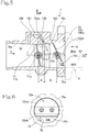
FIG. 6 is a front elevational view of a tumble valve as viewed along the arrow b inFIG. 5 . -
FIG. 7 is a right-hand side elevational view, partly in cross section, of a vehicle-mounted power unit having an intake structure for an internal combustion engine according toEmbodiment 2 of the present invention. - An intake structure for internal combustion engines according to
Embodiment 1 of the present invention will hereinafter be described with reference toFIGS. 1 through 6 . - In the description that follows and the scope of claims, forward, rearward, leftward, rightward, upward, and downward directions and other similar directional expressions will be in accord with directions of a vehicle that incorporates a power unit having an intake structure for internal combustion engines according to the present embodiment. According to the present embodiment, the vehicle is a small-size vehicle or, specifically, a motorcycle.
- Regarding an
intake channel 70 in athrottle body 7 and anintake passageway 80 illustrated inFIGS. 3 and4 , an uppermain passageway 80A and a lowerauxiliary passageway 80B that are separated by apartition plate 81 will be described respectively as "upper" and "lower" sides. - In the drawings, the arrow FR represents a forward direction of the vehicle, LH a leftward direction of the vehicle, RH a rightward direction of the vehicle, and UP an upward direction of the vehicle.
-
FIG. 1 illustrates a right-hand side of amotorcycle 1 including apower unit 3 having an intake structure for internal combustion engines according toEmbodiment 1 of the present invention. - The
motorcycle 1 according to the present embodiment is a scooter-type motorcycle having a frontvehicle body portion 1A and a rearvehicle body portion 1B that are interconnected by a low floor portion 1C. Avehicle body frame 2 that provides a vehicle body skeleton generally includes adowntube 21 and a main pipe 22 (seeFIG. 2 ). - Specifically, the
downtube 21 extends downwardly from ahead pipe 20 of the frontvehicle body portion 1A. Thedowntube 21 is bent horizontally at its lower end and extends rearwardly below the floor portion 1C. As illustrated inFIG. 2 , thedowntube 21 has a rear end coupled to a pair of left and rightmain pipes 22 by ajoint frame 23 disposed transversely across the vehicle. Themain pipes 22 includesslanted portions 22a that rise obliquely upwardly from thejoint frame 23 and are bent progressively less obliquely and extend rearwardly. - A
storage box 11 and afuel tank 12 are supported upwardly by theslanted portions 22a of themain pipes 22. Thestorage box 11 and thefuel tank 12 are covered with a rider'sseat 13 mounted upwardly thereon. Thestorage box 11, thefuel tank 12, and a region beneath the rider'sseat 12 are covered with avehicle body cover 10. - In the front
vehicle body portion 1A, ahandle 14 is pivotally supported on thehead pipe 20, and afront fork 15 extends downwardly from thehandle 14 and has a lower end on which afront wheel 16 is rotatably supported. -
FIG. 2 illustrates a right-hand side of a rear portion of themotorcycle 1 with thevehicle body cover 10 removed therefrom. As illustrated inFIG. 2 ,brackets 24 project nearly from the lower ends of theslanted portions 22a of themain pipes 22. Thepower unit 3 is swingably coupled to and supported on thebrackets 24 bylink members 25. - The
power unit 3 has a front portion as a single-cylinder, four-stroke cycle, air-cooled internal combustion engine (hereinafter referred to simply as "internal combustion engine") 30. Thepower unit 3 includes apower unit case 50 having a front portion as acrankcase 50a in which acrankshaft 51 extending transversely across the vehicle is rotatably supported. Thepower unit 3 is kept at such a posture that a cylinder axis C is inclined largely forwardly and nearly horizontally. Ahanger arm 52 projects forwardly from a lower end of thepower unit case 50 and has an end vertically swingably coupled to thelink members 25 attached to thebrackets 24 of themain pipes 22. - The
power unit 3 includes acylinder block 31, acylinder head 32, and acylinder head cover 33 that are stacked successively one on another and fastened together. Thecylinder block 31, thecylinder head 32, and thecylinder head cover 33 jointly make up theinternal combustion engine 30 in a manner to be inclined largely forwardly and nearly horizontally in the front portion of thepower unit case 50 that serves as thecrankcase 50a. Thepower unit 3 also includes apower transmitting case 55 extending integrally rearwardly on a left side from thecrankcase 50a and housing a belt-type continuously variable transmission, etc. Arear axle 56 as the output shaft of thepower unit 3 is disposed on a rear portion of thepower transmitting case 55. Arear wheel 17 is mounted on therear axle 56. - The
power unit 3 is a so-called swing unit, and a rear cushion, not illustrated, is interposed between thepower transmitting case 55 in a rear potion of thepower unit 3 and rear portions of themain pipes 22. - As illustrated in
FIG. 2 , in an upper portion of thepower unit 3, aninlet pipe 6 extends from an upper portion of thecylinder head 32, which is inclined largely forwardly, of theinternal combustion engine 30 and is bent rearwardly. Theinlet pipe 6 is connected to athrottle body 7 positioned above thecylinder block 31. Anair cleaner device 86 that is connected to thethrottle body 7 by a connectingtube 85 is disposed above thepower transmitting case 55. - An
exhaust pipe 38 extends downwardly from a lower portion of thecylinder head 32, is bent rearwardly, is deflected to a right side, extends rearwardly, and is connected to amuffler 39 on a right side of therear wheel 16. -
FIG. 3 is a sectional side elevational view of thepower unit 3, extracted fromFIG. 2 , that is oriented in substantially the same way as withFIG. 2 . - The cross-section of the lest halves of the
cylinder block 31, thecylinder head 32, and thecylinder head cover 33 of theinternal combustion engine 30 of thepower unit 3 are illustrated. Thepower unit case 50 includes a left case half 50L having amating surface 50b, to be mated with a right case half, not illustrated, illustrated so as to face the viewer ofFIG. 3 . - The
power unit case 50 is made up of theleft case half 50L and the right case half, not illustrated, that are combined together, but can be split from each other. The right case half serves as a right half of thecrankcase 50a. Theleft case half 50L includes a front portion serving as a left half of thecrankcase 50a, and extends rearwardly as thepower transmitting case 55 that houses therein a transmission assembly including the elongate belt-type continuously variable transmission, not illustrated, extending rearwardly between thecrankshaft 51 and therear axle 56 for therear wheel 17 and a speedreducer gear mechanism 57, etc. - The speed
reducer gear mechanism 57 is housed in a right-handopen face 55R of a rear portion of thepower transmitting case 55, and is covered with a speed reducer case, not illustrated. The speedreducer gear mechanism 57 has an output shaft serving as therear axle 56 for therear wheel 17. - Rotational power from the
crankshaft 51 in thecrankcase 50a of theinternal combustion engine 30 is transmitted to therear wheel 17 through the belt-type continuously variable transmission and the speedreducer gear mechanism 57 in thepower transmitting case 55. - The
cylinder block 31 has acylinder bore 31a defined therein. Apiston 34 that is reciprocally movable in thecylinder bore 31a is coupled to acrankpin 51a of thecrankshaft 51 in thecrankcase 50a by a connectingrod 35. - A
combustion chamber 36 is defined between atop surface 34a of thepiston 34 that is slidably fitted in the cylinder bore 31a in thecylinder block 31 and a combustionchamber ceiling surface 32a of thecylinder head 32 faced by thetop surface 34a. - According to the present embodiment, the
internal combustion engine 30 employs a single overhead camshaft (SOHC) two-valve system including avalve operating mechanism 9 disposed in thecylinder head 32. - The
valve operating mechanism 9 is covered with thecylinder head cover 33 superposed on thecylinder head 32. - For transmitting power to the
valve operating mechanism 9 in thecylinder head cover 33, an endless cam chain, not illustrated, is disposed in a cam chain compartment, not illustrated, defined in one side of thecrankcase 50a, thecylinder block 31, and thecylinder head 32 along a direction of thecrankshaft 51 and is trained around acamshaft 91 and thecrankshaft 51. The endless cam chain causes thecamshaft 91 to rotate at a speed that is one-half of thecrankshaft 51 in synchronism therewith. - A spark ignition plug, not illustrated, is inserted in the
cylinder head 32 into thecombustion chamber 36 from the side of thecylinder head 32 opposite to the cam chain compartment, which is the other side of thecrankshaft 51. - As illustrated in
FIG. 3 andFIG. 4 , which is an enlarged view of a major section ofFIG. 3 , thecylinder head 32 where the cylinder axis C is inclined largely forwardly and nearly horizontally has anintake valve opening 40 and an exhaust valve opening 41 that are open in the combustionchamber ceiling surface 32a. Thecylinder head 32 also has anintake port 42 and anexhaust port 43 defined therein that extend respectively from theintake valve opening 40 and the exhaust valve opening 41 while being curved in directions separated vertically away from each other. - The
intake port 42 has an upstream end that is open upwardly of thecylinder head 32 and connected to theinlet pipe 6, jointly defining theintake passageway 80 continuously. Thethrottle body 7 is connected to an upstream side of theinlet pipe 6. - The
exhaust port 43 has a downstream end that is open downwardly of thecylinder head 32 and coupled to the exhaust pipe 38 (seeFIG. 2 ). - The
intake port 42 in thecylinder head 32 is defined by a curvedouter wall 42a in which a tubularintake valve guide 44 is integrally fitted. Anintake valve 46 that is slidably supported in theintake valve guide 44 opens and closes theintake valve opening 40 through which theintake port 42 faces thecombustion chamber 36. - The
exhaust port 43 in thecylinder head 32 is defined by a curvedouter wall 43a in which a tubularexhaust valve guide 45 is integrally fitted. Anexhaust valve 47 that is slidably supported in theexhaust valve guide 45 opens and closes the exhaust valve opening 41 through which theexhaust port 43 faces thecombustion chamber 36. - The
intake valve 46 and theexhaust valve 47 haverespective heads 46a and 47a normally biased to move upwardly by valve springs 48 for closing theintake valve opening 40 and theexhaust valve opening 41, respectively, that face thecombustion chamber 36. As illustrated inFIG. 3 , when anintake rocker arm 94 and anexhaust rocker arm 95 that are swingably held against anintake cam 92 and anexhaust cam 93, respectively, of thecamshaft 91 depress respective stem ends 46b and 47b of theintake valve 46 and theexhaust valve 47, theintake valve 46 and theexhaust valve 47 are opened at predetermined timings, bringing theintake port 42 and thecombustion chamber 36 into fluid communication with each other and also bringing theexhaust port 43 and thecombustion chamber 36 into fluid communication with each other, thereby to introduce an air-fuel mixture into thecombustion chamber 36 and discharge an exhaust gas from thecombustion chamber 36 at predetermined timings. - The
internal combustion engine 30 arranged above incorporates an intake structure for producing a tumbling flow T of a fuel-air mixture, i.e., imparting vertical rotation to a fuel-air mixture, in thecombustion chamber 36 in order to achieve more preferable combustion in thecombustion chamber 36. - Specifically, the
continuous intake passageway 80 is defined by connecting theinlet pipe 6 to the upstream end of theintake port 42 of theinternal combustion engine 30 with aninsulator 61 interposed therebetween. Thethrottle body 7 is connected to the upstream side of theinlet pipe 6. - The
throttle body 7 has theintake channel 70 defined therein that is contiguous to theintake passageway 80 leading to thecombustion chamber 36 in theinternal combustion engine 30. Thethrottle body 7 has an upstream side connected to the air cleaner device 86 (seeFIG. 2 ) through the connectingtube 85. - The
throttle body 7 includes athrottle valve 71 rotatably supported therein by athrottle valve shaft 71a oriented substantially horizontally perpendicularly to a flow direction F in theintake channel 70. Thethrottle valve 71 controls the passageway area of theintake channel 70 to vary for opening and closing theintake channel 70. - The
throttle body 7 also includes atumble valve 72 disposed downstream of thethrottle valve 71 with respect to the flow direction F in theintake channel 70 and rotatably supported in thethrottle body 7 by atumble valve shaft 72a extending parallel to thethrottle valve shaft 71a and oriented substantially horizontally perpendicularly to the flow direction F in theintake channel 70. - The
throttle valve 71 that is disposed in an upstream region of theintake channel 70 in thethrottle body 7 is of the butterfly type and has thethrottle valve shaft 71a and a disk-shapedthrottle valve plate 71b fastened to thethrottle valve shaft 71a by bolts for rotation therewith. - The
throttle valve 71 is rotatable counterclockwise inFIGS. 3 and4 in a valve opening direction and is normally biased by a return spring, not illustrated, to rotate clockwise in a valve closing direction into a fully closed position in which thethrottle valve plate 71b is to be held against aninner surface 70a of theintake channel 70. - As illustrated in
FIG. 5 , thetumble valve 72 that is disposed in theintake channel 70 downstream of thethrottle valve 71 with respect to the flow direction F in theintake channel 70 is of the butterfly type and has thetumble valve shaft 72a and atumble valve plate 72b fastened to thetumble valve shaft 72a by bolts for rotation therewith. Thetumble valve plate 72b includes a semicircular upper plate 72ba extending upwardly and a lower plate 72bb extending downwardly. The lower plate 72bb has arecess 72c defined therein. - The
tumble valve 72 is rotatable counterclockwise inFIGS. 3 and4 in a valve opening direction and is normally biased by a return spring, not illustrated, to rotate clockwise in a valve closing direction into a tumble valve closed position in which the upper plate 72ba of thetumble valve plate 72b is to be held against theinner surface 70a of theintake channel 70. - In the tumble valve closed position, the
recess 72c in the lower plate 72bb of thetumble valve plate 72b defines anopening 70b (seeFIG. 4 ) upon tumble valve closure in theintake channel 70. - The diameter of the
intake channel 70 at a position where thetumble valve 72 is disposed is larger than the diameter of theintake channel 70 at a position where thethrottle valve 71 is disposed, with a slopinginner surface 70c interposed therebetween, for making an intake air flow smooth and facilitating the removal of a mold at the time thethrottle body 7 is cast. - According to the present embodiment, the
intake passageway 80 is divided into upper and lower regions by thepartition plate 81 continuously from theinlet pipe 6 to theintake port 42, i.e., separated into the lowerauxiliary passageway 80B serving as a tumbling flow channel and the uppermain passageway 80A exclusive of the lowerauxiliary passageway 80B. - The
partition plate 81 is made up of an inlet-pipe-side partition plate 81A, an insulator-side partition plate 81B, and an intake-port-side partition plate 81C that are positioned in succession. - The upper
main passageway 80A and the lowerauxiliary passageway 80B are defined as substantially semicircular cross-sectional shapes, respectively, by dividing theintake passageway 80 downstream of thetumble valve 72 into upper and lower regions with thepartition plate 81 that extends longitudinally in theinlet pipe 6 and theintake port 42. - Therefore, the lower
auxiliary passageway 80B in theintake passageway 80 in theinlet pipe 6 that is connected to a downstream side of theintake channel 70 in thethrottle body 7 has an inlet opening 80Ba positioned downstream of therecess 72c in thetumble valve 72, i.e., downstream of theopening 70b upon tumble valve closure in theintake channel 70, when thetumble valve 72 is in a closed position indicated by the solid lines. The uppermain passageway 80A has an inlet opening 80Aa positioned downstream of the upper plate 72ba of thetumble valve plate 72b in theintake channel 70. - A
fuel injection valve 87 is mounted on theinlet pipe 6 so as to extend into the uppermain passageway 80A from above and outside and disposed so as to inject fuel toward theintake valve opening 40. - As illustrated in
FIG. 4 , thepartition plate 81 has adownstream end 81b positioned in theintake port 42 in thecylinder head 32 and bent toward thecylinder block 31 integrally with thecylinder head 32. The lowerauxiliary passageway 80B has a terminal end 80Bb oriented toward the combustionchamber ceiling surface 32a of thecylinder head 32. - Consequently, inasmuch as intake air flowing through the lower
auxiliary passageway 80B can pass above thehead 46a of theintake valve 46 and flow into thecylinder bore 31a, as indicated by the small arrows inFIG. 4 , the tumbling flow T can easily be produced in thecombustion chamber 36. In other words, the lowerauxiliary passageway 80B serves as the tumbling flow channel for producing the tumbling flow T. - The
tumble valve 72 essentially opens and closes the uppermain passageway 80A by controlling, with the upper plate 72ba of thetumble valve plate 72b, the influx of an intake flow into the uppermain passageway 80A, of the pair of the uppermain passageway 80A and the lowerauxiliary passageway 80B that divide the intake flow in theintake passageway 80 downstream of thetumble valve plate 72b. Thetumble valve plate 72b has therecess 72c defined in the lower plate 72bb thereof. - Specifically, in the tumble valve closed position, the upper plate 72ba of the
tumble valve plate 72b is positioned in covering relation to the inlet opening 80Aa of the uppermain passageway 80A to limit the influx of the intake flow. Since the intake flow is guided from therecess 72c in the lower plate 72bb into the lowerauxiliary passageway 80B by thetumble valve plate 72b, the uppermain passageway 80A is essentially closed. - As the
tumble valve 72 rotates in an opening direction, the influx of the intake flows into the uppermain passageway 80A increases. When thetumble valve 72 is in a fully open position, as indicated by the two-dot-and-dash lines inFIGS. 4 and5 , thethrottle valve plate 71b and thebumble valve plate 72b are positioned parallel to the flow direction F in theintake channel 70, allowing the intake flow in theintake channel 70 to flow at a sufficient rate into both the uppermain passageway 80A and the lowerauxiliary passageway 80B and toward thecombustion chamber 36, without being impeded by thethrottle valve 71 and thetumble valve 72. - The
throttle valve 71 is opened or closed when it is turned through a throttle wire, not illustrated, by the rider operating an accelerator grip 75 (seeFIG. 1 ). - When the
accelerator grip 75 is not operated, thethrottle valve 71 is closed by the return spring. An idlingair passageway 100 for supplying intake air at a rate required for idling operation and minimum-load operation of theinternal combustion engine 30 is defined in thethrottle body 7 on an upper side of theintake channel 70 in a manner to provide fluid communication between a region upstream of thethrottle valve 71 and a region downstream of thethrottle valve 71. The idlingair passageway 100 has adownstream outlet 102 defined in the taperedinner surface 70c between thethrottle valve 71 and thetumble valve 72 so as to be open at an upper inner surface 70aa of theintake channel 70. - An
IACV 101 is disposed in the idlingair passageway 100 for controlling a rate at which to supply idling air depending on the operation state of theinternal combustion engine 30. - Consequently, when the
throttle valve 71 is in the closed position and thetumble valve 72 is in the predetermined closed position downstream of thethrottle valve 71, idling air passes through the idlingair passageway 100 and flows out of thedownstream outlet 102 that is open at the upper inner surface 70aa of theintake channel 70. The idling air that flows out into theintake channel 70 is restrained from flowing into the uppermain passageway 80A in theintake passageway 80 by thetumble valve plate 72b of thetumble valve 72, but is directed toward and through theopening 70b upon tumble valve closure defined by therecess 72c in thetumble valve plate 72b, and is guided into the lowerauxiliary passageway 80B and flows toward thecombustion chamber 36. - Inasmuch as the idling
air passageway 100 is defined in the upper side of theintake channel 70, fuel is less likely to accumulate as a gas in the idlingair passageway 100. The idlingair passageway 100 is thus disposed above theintake channel 70. - At the time the
internal combustion engine 30 is operating in an idling mode or in a low-load mode, the intake air flows into thecombustion chamber 36 at an increased speed, thereby intensifying the tumbling flow T (vertical vortex flow) of intake air produced in thecombustion chamber 36. - As the
intake passageway 80 disposed downstream of thetumble valve 72 is divided into the upper and lower regions, the intake flow is controlled by thetumble valve 72 to flow through only the lowerauxiliary passageway 80B toward thecombustion chamber 36. Therefore, the tumbling flow T of intake air produced in thecombustion chamber 36 is further intensified. - When the
intake valve 46 is closed in thecombustion chamber 36, the intake air that has passed through the lowerauxiliary passageway 80B slightly rises toward the uppermain passageway 80A above thehead 46a of theintake valve 46, so that the mixture of intake air and fuel is stirred and uniformized in theintake port 42. - The
throttle valve 71 and thetumble valve 72 are interlinked by an interlinking mechanism, not illustrated, such that thetumble valve 72 is opened in a predetermined relationship depending on the opening of thethrottle valve 71. When thethrottle valve 71 is fully opened under a high load and thetumble valve 72 is in the fully open position, as indicated by the two-dot-and-dash lines inFIG. 4 , thethrottle valve plate 71b and thetumble valve plate 72b are positioned parallel to the flow direction F in theintake channel 70, allowing the intake flow in theintake channel 70 to flow at a sufficient rate into both the uppermain passageway 80A and the lowerauxiliary passageway 80B and toward thecombustion chamber 36, without being impeded by thethrottle valve 71 and thetumble valve 72. - As illustrated in
FIG. 5 , the idlingair passageway 100 includes adownstream passageway 103 defined in the vicinity of thedownstream outlet 102 parallel to thetumble valve plate 72b of thetumble valve 72 when it is closed as viewed along a horizontal direction perpendicular to the flow direction in theintake channel 70 or as viewed in a sectional side elevation of theintake channel 70. Therefore, idling air flowing out of the idlingair passageway 100 is more effectively restrained from flowing into the uppermain passageway 80A by thetumble valve plate 72b and is guided toward the lower plate 72bb of thetumble valve 72 to easily flow through therecess 72c defined in the lower plate 72bb into the lowerauxiliary passageway 80B. - According to the present embodiment, in particular, because the tapered
inner surface 70c that is progressively larger in diameter downstream is provided in theintake channel 70 downstream of thethrottle valve 71, and thedownstream outlet 102 of the idlingair passageway 100 is defined in the taperedinner surface 70c, thedownstream passageway 103 of the idlingair passageway 100 can easily be formed parallel to thetumble valve plate 72b of thetumble valve 72 when it is closed as viewed along the horizontal direction perpendicular to the flow direction F in theintake channel 70. Furthermore, as thedownstream outlet 102 of the idlingair passageway 100 is defined in the taperedinner surface 70c, thedownstream outlet 102 of the idlingair passageway 100 is oriented toward theopening 70b upon tumble valve closure, making it easy for the intake flow in the idlingair passageway 100 to flow into the lowerauxiliary passageway 80B. - Moreover, as illustrated in
FIG. 5 , thedownstream outlet 102 of the idlingair passageway 100 is disposed in a position that is closer to thethrottle valve shaft 71a of thethrottle valve 71 than to thetumble valve shaft 72a of thetumble valve 72. Accordingly, the distance between thedownstream outlet 102 of the idlingair passageway 100 and therecess 72c in the lower plate 72bb of thetumble valve 72 is increased to make it easy for the idling air flowing out of the idlingair passageway 100 to flow from therecess 72c in the lower plate 72bb of thetumble valve plate 72b into the lowerauxiliary passageway 80B. - The intake structure for internal combustion engines according to the present invention as applied to the
power unit 3 as the swing unit has been described above asEmbodiment 1. The intake structure for internal combustion engines according to the present invention is not limited to thepower unit 3 whose cylinder axis C is inclined forwardly and nearly horizontally, but is also applicable to power units of other types. - For example, the intake structure for internal combustion engines according to the present invention is applicable with exactly similar effects to a vehicle-mounted power unit 3' incorporating an internal combustion engine with an erected cylinder axis C as illustrated in
FIG. 7 , i.e., a so-called vertical-type internal combustion engine 30'. - The intake structure thus applied will hereinafter be described below as
Embodiment 2. - The power unit 3' according to
Embodiment 2 illustrated inFIG. 7 is fixedly mounted on the vehicle body frame of a motorcycle at a posture illustrated inFIG. 7 . The power unit 3' includes a power unit case 50', and the internal combustion engine 30' includes acylinder block 31, acylinder head 32, and acylinder head cover 33 that are successively stacked one on another, slightly inclined forwardly, and fastened to a front portion of the power unit case 50'. The internal combustion engine 30' has acrankshaft 51 extending transversely across the vehicle. - A gear transmission apparatus 58' having a
main shaft 58a' and acountershaft 58b' that extend parallel to thecrankshaft 51 is disposed in a rear portion of the power unit case 50'. Thecountershaft 58b' serves as an output shaft. - An
exhaust port 43 is open forwardly of thecylinder head 32 and connected to anexhaust pipe 38, not illustrated. Anintake port 42 is open rearwardly of thecylinder head 32 and connected successively to aninlet pipe 6, athrottle body 7, and a connectingtube 85 rearwardly, i.e., upstream with respect to a flow of intake air. The connectingtube 85 is connected to an air cleaner device, not illustrated. - As with
Embodiment 1, apartition plate 81 is disposed in theinlet pipe 6 and theintake port 42, and athrottle valve 71 and atumble valve 72 are similarly disposed in athrottle body 7. A similaridling air passageway 100 is defined on an upper side of anintake channel 70 in a manner to provide fluid communication between a region upstream of thethrottle valve 71 and a region downstream of thethrottle valve 71. The idlingair passageway 100 has adownstream outlet 102 defined in an upper inner surface 70aa of theintake channel 70 between thethrottle valve 71 and thetumble valve 72, as illustrated inFIG. 5 . - According to
Embodiment 2, therefore, the intake structure for internal combustion engines according to the present invention which is similar toEmbodiment 1 is provided as illustrated inFIG. 7 , and offers similar operation and effects. - Although
Embodiments
Various design changes and modifications may be made therein without departing from the scope of the invention. The present invention covers many various forms of vehicles, internal combustion engines, etc. within the scope of the invention. - For example, the intake structures according to
Embodiments - While the embodiments with the illustrated left and right component layouts have been described above for the sake of convenience, the present invention covers different left and right component layouts within the scope thereof.
- 1···Motorcycle, 2···Vehicle body frame, 3, 3' ···Power unit, 6···Inlet pipe, 7···Throttle body, 14···Handle, 30, 30'···Internal combustion engine, 31···Cylinder block, 31a···Cylinder bore, 32···Cylinder head, 32a···Combustion chamber ceiling surface, 34···Piston, 34a···Top surface, 35···Connecting rod, 36w···Combustion chamber, 40···Intake valve opening, 41···Exhaust valve opening, 42···Intake port, 42a···Curved outer wall, 43···Exhaust port, 46··· Intake valve, 46a···Head, 47···Exhaust valve, 48···Valve spring, 50, 50'···Power unit case, 50L···Left case half, 50a···Crankcase, 51···Crankshaft, 51a···Crankpin, 55···Power transmitting case, 58'···Gear transmission apparatus, 58a'···Main shaft, 58b'···Countershaft, 70···Intake channel, 70a···Inner surface, 70aa···Upper inner surface, 70b···Opening upon tumble valve closure, 70c···Tapered inner surface, 71···Throttle valve, 71a···Throttle valve shaft, 71···Throttle valve plate, 72···Tumble valve, 72a···Tumble valve shaft, 72b···Tumble valve plate, 72ba···Upper plate, 72bb···Lower plate, 72c···Recess, 80···Intake passageway, 80A···Upper main passageway, 80Aa···Inlet opening, 80B···Lower auxiliary passageway, 80Ba···Inlet opening, 80Bb···Terminal end, 81···Partition plate, 81b···Downstream end, 100···Idling air passageway, 101···Idling air control valve, 102···Downstream outlet, 103···Downstream passageway, C···Cylinder axis, F···Flow direction (of the intake channel 70), T···Tumbling flow
Claims (4)
- An intake structure for an internal combustion engine, in which:the internal combustion engine (30, 30') having a combustion chamber (36) includes a cylinder block (31) and a cylinder head (32), the cylinder head (32) having an intake port (42) and an exhaust port (43) defined therein;an inlet pipe (6) is connected to the intake port (42), defining a continuous intake passageway (80);a throttle body (7) having an intake channel (70) continuing to the intake passageway (80) is connected to an upstream side of the inlet pipe (6) with respect to an intake flow therein;the throttle body (7) is provided with a throttle valve (71) and a tumble valve (72) disposed downstream thereof with respect to a flow direction (F) of the intake flow in the intake channel (70); andthe intake passageway (80) is divided by a partition plate (81) downstream of the tumble valve (72) into an upper main passageway (80A) and a lower auxiliary passageway (80B) serving as a tumbling flow channel for producing a tumbling flow in the combustion chamber (36),wherein an idling air passageway (100) is defined in an upper side of the intake channel (70) to provide fluid communication between a region upstream of the throttle valve (71) and a region downstream of the throttle valve (71), the idling air passageway (100) having a downstream outlet (102), the downstream outlet (102) being defined in an upper inner surface (70aa) of the intake channel (70) between the throttle valve (71) and the tumble valve (72), andthe tumble valve (72) has a tumble valve plate (72b) and a recess (72c) defined therein, the tumble valve (72) being arranged such that when the throttle valve (71) is fully closed, idling air flowing out of the idling air passageway (100) is restrained by the tumble valve plate (72b) from flowing into the upper main passageway (80A) and is guided from the recess (72c) to the lower auxiliary passageway (80B).
- The intake structure for an internal combustion engines as claimed in claim 1, wherein the idling air passageway (100) has a downstream passageway (103) leading to the downstream outlet (102), the downstream passageway (103) being defined parallel to the tumble valve plate (72b) of the tumble valve (72) when the tumble valve (72) is closed as viewed in a horizontal direction perpendicular to the flow direction (F) in the intake channel (70).
- The intake structure for an internal combustion engine as claimed in claim 2, wherein a tapered inner surface (70c) being progressively larger in diameter toward a downstream side is provided in the intake channel (70) downstream of the throttle valve (71), the downstream outlet (102) of the idling air passageway (100) being defined in the tapered inner surface (70c).
- The intake structure for an internal combustion engine as claimed in any one of claims 1 through 3, wherein the downstream outlet (102) of the idling air passageway (100) is disposed in a position closer to a throttle valve shaft (71a) of the throttle valve (71) than to a tumble valve shaft (72a) of the tumble valve (72) .
Applications Claiming Priority (2)
| Application Number | Priority Date | Filing Date | Title |
|---|---|---|---|
| JP2017045638 | 2017-03-10 | ||
| PCT/JP2018/007227 WO2018163912A1 (en) | 2017-03-10 | 2018-02-27 | Air intake structure for internal combustion engine |
Publications (3)
| Publication Number | Publication Date |
|---|---|
| EP3594471A1 true EP3594471A1 (en) | 2020-01-15 |
| EP3594471A4 EP3594471A4 (en) | 2020-03-18 |
| EP3594471B1 EP3594471B1 (en) | 2023-05-10 |
Family
ID=63448492
Family Applications (1)
| Application Number | Title | Priority Date | Filing Date |
|---|---|---|---|
| EP18763803.6A Active EP3594471B1 (en) | 2017-03-10 | 2018-02-27 | Air intake structure for internal combustion engine |
Country Status (4)
| Country | Link |
|---|---|
| EP (1) | EP3594471B1 (en) |
| JP (1) | JP6714764B2 (en) |
| BR (1) | BR112019017635B1 (en) |
| WO (1) | WO2018163912A1 (en) |
Cited By (2)
| Publication number | Priority date | Publication date | Assignee | Title |
|---|---|---|---|---|
| CN109707856A (en) * | 2019-02-02 | 2019-05-03 | 联合汽车电子有限公司 | Valve body connects system and gas recirculation system |
| EP3650679A4 (en) * | 2017-07-05 | 2020-08-19 | Honda Motor Co., Ltd. | Air intake structure for internal combustion engine |
Families Citing this family (4)
| Publication number | Priority date | Publication date | Assignee | Title |
|---|---|---|---|---|
| JP2021188588A (en) * | 2020-06-03 | 2021-12-13 | 株式会社Subaru | engine |
| WO2022176860A1 (en) * | 2021-02-18 | 2022-08-25 | 本田技研工業株式会社 | Intake structure for internal combustion engine |
| WO2023053308A1 (en) * | 2021-09-29 | 2023-04-06 | 本田技研工業株式会社 | Air intake device for internal combustion engine |
| WO2023053346A1 (en) * | 2021-09-30 | 2023-04-06 | 本田技研工業株式会社 | Air intake device for internal combustion engine |
Family Cites Families (14)
| Publication number | Priority date | Publication date | Assignee | Title |
|---|---|---|---|---|
| JPS54106719A (en) * | 1978-02-10 | 1979-08-22 | Yamaha Motor Co Ltd | Suction apparatus for multi-cylinder engine |
| JPS6056261B2 (en) * | 1978-07-14 | 1985-12-09 | ヤマハ発動機株式会社 | Fuel-injected multi-cylinder internal combustion engine |
| JPS5925878B2 (en) | 1980-02-04 | 1984-06-21 | 三洋電機株式会社 | Silencer for hermetic compressor |
| JPH0633736B2 (en) * | 1985-01-07 | 1994-05-02 | 日産自動車株式会社 | Intake path control device for internal combustion engine |
| JP3217206B2 (en) * | 1994-05-09 | 2001-10-09 | 株式会社日立製作所 | Internal combustion engine intake pipe |
| JP2002070587A (en) * | 2000-08-30 | 2002-03-08 | Mikuni Corp | Throttle body having fully closed angle zero valve |
| JP2002221036A (en) | 2001-01-26 | 2002-08-09 | Fuji Heavy Ind Ltd | Intake system for engine |
| JP2006329016A (en) * | 2005-05-24 | 2006-12-07 | Toyota Motor Corp | Intake device for internal combustion engine |
| JP2007068378A (en) * | 2005-09-02 | 2007-03-15 | Denso Corp | Motor actuator |
| JP2007071163A (en) * | 2005-09-08 | 2007-03-22 | Toyota Motor Corp | Intake port structure for internal combustion engine |
| TW201024528A (en) * | 2008-12-26 | 2010-07-01 | Kwang Yang Motor Co | Throttle valve and device thereof |
| DE102009000166A1 (en) * | 2009-01-13 | 2010-07-15 | Robert Bosch Gmbh | throttle device |
| JP2015155684A (en) * | 2014-02-21 | 2015-08-27 | トヨタ紡織株式会社 | Intake duct |
| JP6268604B2 (en) * | 2014-09-22 | 2018-01-31 | 本田技研工業株式会社 | Intake structure of internal combustion engine |
-
2018
- 2018-02-27 WO PCT/JP2018/007227 patent/WO2018163912A1/en active Application Filing
- 2018-02-27 BR BR112019017635-7A patent/BR112019017635B1/en active IP Right Grant
- 2018-02-27 EP EP18763803.6A patent/EP3594471B1/en active Active
- 2018-02-27 JP JP2019504495A patent/JP6714764B2/en active Active
Cited By (2)
| Publication number | Priority date | Publication date | Assignee | Title |
|---|---|---|---|---|
| EP3650679A4 (en) * | 2017-07-05 | 2020-08-19 | Honda Motor Co., Ltd. | Air intake structure for internal combustion engine |
| CN109707856A (en) * | 2019-02-02 | 2019-05-03 | 联合汽车电子有限公司 | Valve body connects system and gas recirculation system |
Also Published As
| Publication number | Publication date |
|---|---|
| BR112019017635A2 (en) | 2020-03-31 |
| JP6714764B2 (en) | 2020-06-24 |
| EP3594471A4 (en) | 2020-03-18 |
| BR112019017635B1 (en) | 2023-10-31 |
| EP3594471B1 (en) | 2023-05-10 |
| JPWO2018163912A1 (en) | 2020-01-16 |
| WO2018163912A1 (en) | 2018-09-13 |
Similar Documents
| Publication | Publication Date | Title |
|---|---|---|
| EP3594471B1 (en) | Air intake structure for internal combustion engine | |
| EP3428433B1 (en) | Internal combustion engine intake structure | |
| JP6262587B2 (en) | Intake structure of internal combustion engine | |
| EP3650679B1 (en) | Air intake structure for internal combustion engine | |
| EP3650671B1 (en) | Internal combustion engine intake structure | |
| JP6691564B2 (en) | Intake passage of internal combustion engine | |
| US9890703B2 (en) | Fixing structure for exhaust gas sensor of internal combustion engine | |
| WO2018163909A1 (en) | Air intake device for internal combustion engine | |
| EP4116553A1 (en) | Intake control device for saddle-type vehicle internal combustion engine | |
| WO2021181547A1 (en) | Intake device of internal combustion engine for saddle-type vehicle | |
| JP6824218B2 (en) | Sub-combustion chamber of internal combustion engine | |
| EP4123139A1 (en) | Intake structure for internal combustion engine | |
| JP2007120480A (en) | Internal combustion engine equipped with secondary air supply device and breather device | |
| US20120222650A1 (en) | Throttle body configured to provide turbulent air flow to a combustion chamber of an engine, and engine including same | |
| JP2018150817A (en) | Suction structure for internal combustion engine | |
| JP6564523B2 (en) | Intake device for internal combustion engine | |
| WO2023053308A1 (en) | Air intake device for internal combustion engine | |
| CN111608817B (en) | Saddle-ride type internal combustion engine for vehicle | |
| WO2022209880A1 (en) | Air suction device for internal combustion engine | |
| JPH05179971A (en) | Reed valve of two cycle engine | |
| JP6186299B2 (en) | Air intake structure for saddle-ride type vehicles | |
| JP2015113822A (en) | Intake system for engine | |
| JPH0814060A (en) | Engine | |
| JPH05179970A (en) | Intake passage construction for two cycle engine provided with reed valve |
Legal Events
| Date | Code | Title | Description |
|---|---|---|---|
| STAA | Information on the status of an ep patent application or granted ep patent |
Free format text: STATUS: THE INTERNATIONAL PUBLICATION HAS BEEN MADE |
|
| PUAI | Public reference made under article 153(3) epc to a published international application that has entered the european phase |
Free format text: ORIGINAL CODE: 0009012 |
|
| STAA | Information on the status of an ep patent application or granted ep patent |
Free format text: STATUS: REQUEST FOR EXAMINATION WAS MADE |
|
| 17P | Request for examination filed |
Effective date: 20190806 |
|
| AK | Designated contracting states |
Kind code of ref document: A1 Designated state(s): AL AT BE BG CH CY CZ DE DK EE ES FI FR GB GR HR HU IE IS IT LI LT LU LV MC MK MT NL NO PL PT RO RS SE SI SK SM TR |
|
| AX | Request for extension of the european patent |
Extension state: BA ME |
|
| A4 | Supplementary search report drawn up and despatched |
Effective date: 20200213 |
|
| RIC1 | Information provided on ipc code assigned before grant |
Ipc: F02M 35/108 20060101ALI20200207BHEP Ipc: F02M 3/14 20060101ALI20200207BHEP Ipc: F02B 31/06 20060101AFI20200207BHEP Ipc: F02B 31/08 20060101ALI20200207BHEP Ipc: F02M 69/32 20060101ALI20200207BHEP Ipc: F02D 9/10 20060101ALI20200207BHEP Ipc: F02B 31/04 20060101ALI20200207BHEP Ipc: F02M 35/10 20060101ALI20200207BHEP Ipc: F02M 3/12 20060101ALI20200207BHEP |
|
| DAV | Request for validation of the european patent (deleted) | ||
| DAX | Request for extension of the european patent (deleted) | ||
| STAA | Information on the status of an ep patent application or granted ep patent |
Free format text: STATUS: EXAMINATION IS IN PROGRESS |
|
| STAA | Information on the status of an ep patent application or granted ep patent |
Free format text: STATUS: EXAMINATION IS IN PROGRESS |
|
| 17Q | First examination report despatched |
Effective date: 20201117 |
|
| GRAP | Despatch of communication of intention to grant a patent |
Free format text: ORIGINAL CODE: EPIDOSNIGR1 |
|
| STAA | Information on the status of an ep patent application or granted ep patent |
Free format text: STATUS: GRANT OF PATENT IS INTENDED |
|
| INTG | Intention to grant announced |
Effective date: 20230110 |
|
| GRAS | Grant fee paid |
Free format text: ORIGINAL CODE: EPIDOSNIGR3 |
|
| GRAA | (expected) grant |
Free format text: ORIGINAL CODE: 0009210 |
|
| STAA | Information on the status of an ep patent application or granted ep patent |
Free format text: STATUS: THE PATENT HAS BEEN GRANTED |
|
| RIN1 | Information on inventor provided before grant (corrected) |
Inventor name: CHO, MASAKI Inventor name: SHOMURA, TAKAAKI Inventor name: NAKAMURA, YOHEI |
|
| AK | Designated contracting states |
Kind code of ref document: B1 Designated state(s): AL AT BE BG CH CY CZ DE DK EE ES FI FR GB GR HR HU IE IS IT LI LT LU LV MC MK MT NL NO PL PT RO RS SE SI SK SM TR |
|
| REG | Reference to a national code |
Ref country code: GB Ref legal event code: FG4D |
|
| REG | Reference to a national code |
Ref country code: AT Ref legal event code: REF Ref document number: 1566879 Country of ref document: AT Kind code of ref document: T Effective date: 20230515 Ref country code: CH Ref legal event code: EP |
|
| REG | Reference to a national code |
Ref country code: DE Ref legal event code: R096 Ref document number: 602018049656 Country of ref document: DE |
|
| REG | Reference to a national code |
Ref country code: IE Ref legal event code: FG4D |
|
| REG | Reference to a national code |
Ref country code: LT Ref legal event code: MG9D |
|
| REG | Reference to a national code |
Ref country code: NL Ref legal event code: MP Effective date: 20230510 |
|
| REG | Reference to a national code |
Ref country code: AT Ref legal event code: MK05 Ref document number: 1566879 Country of ref document: AT Kind code of ref document: T Effective date: 20230510 |
|
| PG25 | Lapsed in a contracting state [announced via postgrant information from national office to epo] |
Ref country code: SE Free format text: LAPSE BECAUSE OF FAILURE TO SUBMIT A TRANSLATION OF THE DESCRIPTION OR TO PAY THE FEE WITHIN THE PRESCRIBED TIME-LIMIT Effective date: 20230510 Ref country code: PT Free format text: LAPSE BECAUSE OF FAILURE TO SUBMIT A TRANSLATION OF THE DESCRIPTION OR TO PAY THE FEE WITHIN THE PRESCRIBED TIME-LIMIT Effective date: 20230911 Ref country code: NO Free format text: LAPSE BECAUSE OF FAILURE TO SUBMIT A TRANSLATION OF THE DESCRIPTION OR TO PAY THE FEE WITHIN THE PRESCRIBED TIME-LIMIT Effective date: 20230810 Ref country code: NL Free format text: LAPSE BECAUSE OF FAILURE TO SUBMIT A TRANSLATION OF THE DESCRIPTION OR TO PAY THE FEE WITHIN THE PRESCRIBED TIME-LIMIT Effective date: 20230510 Ref country code: ES Free format text: LAPSE BECAUSE OF FAILURE TO SUBMIT A TRANSLATION OF THE DESCRIPTION OR TO PAY THE FEE WITHIN THE PRESCRIBED TIME-LIMIT Effective date: 20230510 Ref country code: AT Free format text: LAPSE BECAUSE OF FAILURE TO SUBMIT A TRANSLATION OF THE DESCRIPTION OR TO PAY THE FEE WITHIN THE PRESCRIBED TIME-LIMIT Effective date: 20230510 |
|
| PG25 | Lapsed in a contracting state [announced via postgrant information from national office to epo] |
Ref country code: RS Free format text: LAPSE BECAUSE OF FAILURE TO SUBMIT A TRANSLATION OF THE DESCRIPTION OR TO PAY THE FEE WITHIN THE PRESCRIBED TIME-LIMIT Effective date: 20230510 Ref country code: PL Free format text: LAPSE BECAUSE OF FAILURE TO SUBMIT A TRANSLATION OF THE DESCRIPTION OR TO PAY THE FEE WITHIN THE PRESCRIBED TIME-LIMIT Effective date: 20230510 Ref country code: LV Free format text: LAPSE BECAUSE OF FAILURE TO SUBMIT A TRANSLATION OF THE DESCRIPTION OR TO PAY THE FEE WITHIN THE PRESCRIBED TIME-LIMIT Effective date: 20230510 Ref country code: LT Free format text: LAPSE BECAUSE OF FAILURE TO SUBMIT A TRANSLATION OF THE DESCRIPTION OR TO PAY THE FEE WITHIN THE PRESCRIBED TIME-LIMIT Effective date: 20230510 Ref country code: IS Free format text: LAPSE BECAUSE OF FAILURE TO SUBMIT A TRANSLATION OF THE DESCRIPTION OR TO PAY THE FEE WITHIN THE PRESCRIBED TIME-LIMIT Effective date: 20230910 Ref country code: HR Free format text: LAPSE BECAUSE OF FAILURE TO SUBMIT A TRANSLATION OF THE DESCRIPTION OR TO PAY THE FEE WITHIN THE PRESCRIBED TIME-LIMIT Effective date: 20230510 Ref country code: GR Free format text: LAPSE BECAUSE OF FAILURE TO SUBMIT A TRANSLATION OF THE DESCRIPTION OR TO PAY THE FEE WITHIN THE PRESCRIBED TIME-LIMIT Effective date: 20230811 |
|
| PG25 | Lapsed in a contracting state [announced via postgrant information from national office to epo] |
Ref country code: FI Free format text: LAPSE BECAUSE OF FAILURE TO SUBMIT A TRANSLATION OF THE DESCRIPTION OR TO PAY THE FEE WITHIN THE PRESCRIBED TIME-LIMIT Effective date: 20230510 |
|
| PG25 | Lapsed in a contracting state [announced via postgrant information from national office to epo] |
Ref country code: SK Free format text: LAPSE BECAUSE OF FAILURE TO SUBMIT A TRANSLATION OF THE DESCRIPTION OR TO PAY THE FEE WITHIN THE PRESCRIBED TIME-LIMIT Effective date: 20230510 |
|
| PG25 | Lapsed in a contracting state [announced via postgrant information from national office to epo] |
Ref country code: SM Free format text: LAPSE BECAUSE OF FAILURE TO SUBMIT A TRANSLATION OF THE DESCRIPTION OR TO PAY THE FEE WITHIN THE PRESCRIBED TIME-LIMIT Effective date: 20230510 Ref country code: SK Free format text: LAPSE BECAUSE OF FAILURE TO SUBMIT A TRANSLATION OF THE DESCRIPTION OR TO PAY THE FEE WITHIN THE PRESCRIBED TIME-LIMIT Effective date: 20230510 Ref country code: RO Free format text: LAPSE BECAUSE OF FAILURE TO SUBMIT A TRANSLATION OF THE DESCRIPTION OR TO PAY THE FEE WITHIN THE PRESCRIBED TIME-LIMIT Effective date: 20230510 Ref country code: EE Free format text: LAPSE BECAUSE OF FAILURE TO SUBMIT A TRANSLATION OF THE DESCRIPTION OR TO PAY THE FEE WITHIN THE PRESCRIBED TIME-LIMIT Effective date: 20230510 Ref country code: DK Free format text: LAPSE BECAUSE OF FAILURE TO SUBMIT A TRANSLATION OF THE DESCRIPTION OR TO PAY THE FEE WITHIN THE PRESCRIBED TIME-LIMIT Effective date: 20230510 Ref country code: CZ Free format text: LAPSE BECAUSE OF FAILURE TO SUBMIT A TRANSLATION OF THE DESCRIPTION OR TO PAY THE FEE WITHIN THE PRESCRIBED TIME-LIMIT Effective date: 20230510 |
|
| REG | Reference to a national code |
Ref country code: DE Ref legal event code: R097 Ref document number: 602018049656 Country of ref document: DE |
|
| PLBE | No opposition filed within time limit |
Free format text: ORIGINAL CODE: 0009261 |
|
| STAA | Information on the status of an ep patent application or granted ep patent |
Free format text: STATUS: NO OPPOSITION FILED WITHIN TIME LIMIT |
|
| 26N | No opposition filed |
Effective date: 20240213 |