EP3594046A1 - Power system of electric vehicle,control method and electric vehicle - Google Patents
Power system of electric vehicle,control method and electric vehicle Download PDFInfo
- Publication number
- EP3594046A1 EP3594046A1 EP19184135.2A EP19184135A EP3594046A1 EP 3594046 A1 EP3594046 A1 EP 3594046A1 EP 19184135 A EP19184135 A EP 19184135A EP 3594046 A1 EP3594046 A1 EP 3594046A1
- Authority
- EP
- European Patent Office
- Prior art keywords
- drive motor
- low voltage
- electronic controller
- auxiliary drive
- high voltage
- Prior art date
- Legal status (The legal status is an assumption and is not a legal conclusion. Google has not performed a legal analysis and makes no representation as to the accuracy of the status listed.)
- Granted
Links
Images



Classifications
-
- B—PERFORMING OPERATIONS; TRANSPORTING
- B60—VEHICLES IN GENERAL
- B60L—PROPULSION OF ELECTRICALLY-PROPELLED VEHICLES; SUPPLYING ELECTRIC POWER FOR AUXILIARY EQUIPMENT OF ELECTRICALLY-PROPELLED VEHICLES; ELECTRODYNAMIC BRAKE SYSTEMS FOR VEHICLES IN GENERAL; MAGNETIC SUSPENSION OR LEVITATION FOR VEHICLES; MONITORING OPERATING VARIABLES OF ELECTRICALLY-PROPELLED VEHICLES; ELECTRIC SAFETY DEVICES FOR ELECTRICALLY-PROPELLED VEHICLES
- B60L3/00—Electric devices on electrically-propelled vehicles for safety purposes; Monitoring operating variables, e.g. speed, deceleration or energy consumption
- B60L3/0023—Detecting, eliminating, remedying or compensating for drive train abnormalities, e.g. failures within the drive train
- B60L3/0046—Detecting, eliminating, remedying or compensating for drive train abnormalities, e.g. failures within the drive train relating to electric energy storage systems, e.g. batteries or capacitors
-
- B—PERFORMING OPERATIONS; TRANSPORTING
- B60—VEHICLES IN GENERAL
- B60L—PROPULSION OF ELECTRICALLY-PROPELLED VEHICLES; SUPPLYING ELECTRIC POWER FOR AUXILIARY EQUIPMENT OF ELECTRICALLY-PROPELLED VEHICLES; ELECTRODYNAMIC BRAKE SYSTEMS FOR VEHICLES IN GENERAL; MAGNETIC SUSPENSION OR LEVITATION FOR VEHICLES; MONITORING OPERATING VARIABLES OF ELECTRICALLY-PROPELLED VEHICLES; ELECTRIC SAFETY DEVICES FOR ELECTRICALLY-PROPELLED VEHICLES
- B60L1/00—Supplying electric power to auxiliary equipment of vehicles
- B60L1/003—Supplying electric power to auxiliary equipment of vehicles to auxiliary motors, e.g. for pumps, compressors
-
- B—PERFORMING OPERATIONS; TRANSPORTING
- B60—VEHICLES IN GENERAL
- B60L—PROPULSION OF ELECTRICALLY-PROPELLED VEHICLES; SUPPLYING ELECTRIC POWER FOR AUXILIARY EQUIPMENT OF ELECTRICALLY-PROPELLED VEHICLES; ELECTRODYNAMIC BRAKE SYSTEMS FOR VEHICLES IN GENERAL; MAGNETIC SUSPENSION OR LEVITATION FOR VEHICLES; MONITORING OPERATING VARIABLES OF ELECTRICALLY-PROPELLED VEHICLES; ELECTRIC SAFETY DEVICES FOR ELECTRICALLY-PROPELLED VEHICLES
- B60L15/00—Methods, circuits, or devices for controlling the traction-motor speed of electrically-propelled vehicles
- B60L15/007—Physical arrangements or structures of drive train converters specially adapted for the propulsion motors of electric vehicles
-
- B—PERFORMING OPERATIONS; TRANSPORTING
- B60—VEHICLES IN GENERAL
- B60L—PROPULSION OF ELECTRICALLY-PROPELLED VEHICLES; SUPPLYING ELECTRIC POWER FOR AUXILIARY EQUIPMENT OF ELECTRICALLY-PROPELLED VEHICLES; ELECTRODYNAMIC BRAKE SYSTEMS FOR VEHICLES IN GENERAL; MAGNETIC SUSPENSION OR LEVITATION FOR VEHICLES; MONITORING OPERATING VARIABLES OF ELECTRICALLY-PROPELLED VEHICLES; ELECTRIC SAFETY DEVICES FOR ELECTRICALLY-PROPELLED VEHICLES
- B60L15/00—Methods, circuits, or devices for controlling the traction-motor speed of electrically-propelled vehicles
- B60L15/20—Methods, circuits, or devices for controlling the traction-motor speed of electrically-propelled vehicles for control of the vehicle or its driving motor to achieve a desired performance, e.g. speed, torque, programmed variation of speed
-
- B—PERFORMING OPERATIONS; TRANSPORTING
- B60—VEHICLES IN GENERAL
- B60L—PROPULSION OF ELECTRICALLY-PROPELLED VEHICLES; SUPPLYING ELECTRIC POWER FOR AUXILIARY EQUIPMENT OF ELECTRICALLY-PROPELLED VEHICLES; ELECTRODYNAMIC BRAKE SYSTEMS FOR VEHICLES IN GENERAL; MAGNETIC SUSPENSION OR LEVITATION FOR VEHICLES; MONITORING OPERATING VARIABLES OF ELECTRICALLY-PROPELLED VEHICLES; ELECTRIC SAFETY DEVICES FOR ELECTRICALLY-PROPELLED VEHICLES
- B60L15/00—Methods, circuits, or devices for controlling the traction-motor speed of electrically-propelled vehicles
- B60L15/32—Control or regulation of multiple-unit electrically-propelled vehicles
- B60L15/38—Control or regulation of multiple-unit electrically-propelled vehicles with automatic control
-
- B—PERFORMING OPERATIONS; TRANSPORTING
- B60—VEHICLES IN GENERAL
- B60L—PROPULSION OF ELECTRICALLY-PROPELLED VEHICLES; SUPPLYING ELECTRIC POWER FOR AUXILIARY EQUIPMENT OF ELECTRICALLY-PROPELLED VEHICLES; ELECTRODYNAMIC BRAKE SYSTEMS FOR VEHICLES IN GENERAL; MAGNETIC SUSPENSION OR LEVITATION FOR VEHICLES; MONITORING OPERATING VARIABLES OF ELECTRICALLY-PROPELLED VEHICLES; ELECTRIC SAFETY DEVICES FOR ELECTRICALLY-PROPELLED VEHICLES
- B60L3/00—Electric devices on electrically-propelled vehicles for safety purposes; Monitoring operating variables, e.g. speed, deceleration or energy consumption
- B60L3/0007—Measures or means for preventing or attenuating collisions
-
- B—PERFORMING OPERATIONS; TRANSPORTING
- B60—VEHICLES IN GENERAL
- B60L—PROPULSION OF ELECTRICALLY-PROPELLED VEHICLES; SUPPLYING ELECTRIC POWER FOR AUXILIARY EQUIPMENT OF ELECTRICALLY-PROPELLED VEHICLES; ELECTRODYNAMIC BRAKE SYSTEMS FOR VEHICLES IN GENERAL; MAGNETIC SUSPENSION OR LEVITATION FOR VEHICLES; MONITORING OPERATING VARIABLES OF ELECTRICALLY-PROPELLED VEHICLES; ELECTRIC SAFETY DEVICES FOR ELECTRICALLY-PROPELLED VEHICLES
- B60L50/00—Electric propulsion with power supplied within the vehicle
- B60L50/50—Electric propulsion with power supplied within the vehicle using propulsion power supplied by batteries or fuel cells
- B60L50/60—Electric propulsion with power supplied within the vehicle using propulsion power supplied by batteries or fuel cells using power supplied by batteries
-
- B—PERFORMING OPERATIONS; TRANSPORTING
- B60—VEHICLES IN GENERAL
- B60L—PROPULSION OF ELECTRICALLY-PROPELLED VEHICLES; SUPPLYING ELECTRIC POWER FOR AUXILIARY EQUIPMENT OF ELECTRICALLY-PROPELLED VEHICLES; ELECTRODYNAMIC BRAKE SYSTEMS FOR VEHICLES IN GENERAL; MAGNETIC SUSPENSION OR LEVITATION FOR VEHICLES; MONITORING OPERATING VARIABLES OF ELECTRICALLY-PROPELLED VEHICLES; ELECTRIC SAFETY DEVICES FOR ELECTRICALLY-PROPELLED VEHICLES
- B60L58/00—Methods or circuit arrangements for monitoring or controlling batteries or fuel cells, specially adapted for electric vehicles
- B60L58/10—Methods or circuit arrangements for monitoring or controlling batteries or fuel cells, specially adapted for electric vehicles for monitoring or controlling batteries
- B60L58/12—Methods or circuit arrangements for monitoring or controlling batteries or fuel cells, specially adapted for electric vehicles for monitoring or controlling batteries responding to state of charge [SoC]
-
- B—PERFORMING OPERATIONS; TRANSPORTING
- B60—VEHICLES IN GENERAL
- B60L—PROPULSION OF ELECTRICALLY-PROPELLED VEHICLES; SUPPLYING ELECTRIC POWER FOR AUXILIARY EQUIPMENT OF ELECTRICALLY-PROPELLED VEHICLES; ELECTRODYNAMIC BRAKE SYSTEMS FOR VEHICLES IN GENERAL; MAGNETIC SUSPENSION OR LEVITATION FOR VEHICLES; MONITORING OPERATING VARIABLES OF ELECTRICALLY-PROPELLED VEHICLES; ELECTRIC SAFETY DEVICES FOR ELECTRICALLY-PROPELLED VEHICLES
- B60L58/00—Methods or circuit arrangements for monitoring or controlling batteries or fuel cells, specially adapted for electric vehicles
- B60L58/10—Methods or circuit arrangements for monitoring or controlling batteries or fuel cells, specially adapted for electric vehicles for monitoring or controlling batteries
- B60L58/18—Methods or circuit arrangements for monitoring or controlling batteries or fuel cells, specially adapted for electric vehicles for monitoring or controlling batteries of two or more battery modules
- B60L58/20—Methods or circuit arrangements for monitoring or controlling batteries or fuel cells, specially adapted for electric vehicles for monitoring or controlling batteries of two or more battery modules having different nominal voltages
-
- H—ELECTRICITY
- H02—GENERATION; CONVERSION OR DISTRIBUTION OF ELECTRIC POWER
- H02P—CONTROL OR REGULATION OF ELECTRIC MOTORS, ELECTRIC GENERATORS OR DYNAMO-ELECTRIC CONVERTERS; CONTROLLING TRANSFORMERS, REACTORS OR CHOKE COILS
- H02P5/00—Arrangements specially adapted for regulating or controlling the speed or torque of two or more electric motors
- H02P5/74—Arrangements specially adapted for regulating or controlling the speed or torque of two or more electric motors controlling two or more AC dynamo-electric motors
-
- B—PERFORMING OPERATIONS; TRANSPORTING
- B60—VEHICLES IN GENERAL
- B60L—PROPULSION OF ELECTRICALLY-PROPELLED VEHICLES; SUPPLYING ELECTRIC POWER FOR AUXILIARY EQUIPMENT OF ELECTRICALLY-PROPELLED VEHICLES; ELECTRODYNAMIC BRAKE SYSTEMS FOR VEHICLES IN GENERAL; MAGNETIC SUSPENSION OR LEVITATION FOR VEHICLES; MONITORING OPERATING VARIABLES OF ELECTRICALLY-PROPELLED VEHICLES; ELECTRIC SAFETY DEVICES FOR ELECTRICALLY-PROPELLED VEHICLES
- B60L2220/00—Electrical machine types; Structures or applications thereof
- B60L2220/50—Structural details of electrical machines
- B60L2220/54—Windings for different functions
-
- B—PERFORMING OPERATIONS; TRANSPORTING
- B60—VEHICLES IN GENERAL
- B60L—PROPULSION OF ELECTRICALLY-PROPELLED VEHICLES; SUPPLYING ELECTRIC POWER FOR AUXILIARY EQUIPMENT OF ELECTRICALLY-PROPELLED VEHICLES; ELECTRODYNAMIC BRAKE SYSTEMS FOR VEHICLES IN GENERAL; MAGNETIC SUSPENSION OR LEVITATION FOR VEHICLES; MONITORING OPERATING VARIABLES OF ELECTRICALLY-PROPELLED VEHICLES; ELECTRIC SAFETY DEVICES FOR ELECTRICALLY-PROPELLED VEHICLES
- B60L2220/00—Electrical machine types; Structures or applications thereof
- B60L2220/50—Structural details of electrical machines
- B60L2220/58—Structural details of electrical machines with more than three phases
-
- B—PERFORMING OPERATIONS; TRANSPORTING
- B60—VEHICLES IN GENERAL
- B60L—PROPULSION OF ELECTRICALLY-PROPELLED VEHICLES; SUPPLYING ELECTRIC POWER FOR AUXILIARY EQUIPMENT OF ELECTRICALLY-PROPELLED VEHICLES; ELECTRODYNAMIC BRAKE SYSTEMS FOR VEHICLES IN GENERAL; MAGNETIC SUSPENSION OR LEVITATION FOR VEHICLES; MONITORING OPERATING VARIABLES OF ELECTRICALLY-PROPELLED VEHICLES; ELECTRIC SAFETY DEVICES FOR ELECTRICALLY-PROPELLED VEHICLES
- B60L2240/00—Control parameters of input or output; Target parameters
- B60L2240/40—Drive Train control parameters
- B60L2240/54—Drive Train control parameters related to batteries
- B60L2240/547—Voltage
-
- B—PERFORMING OPERATIONS; TRANSPORTING
- B60—VEHICLES IN GENERAL
- B60Y—INDEXING SCHEME RELATING TO ASPECTS CROSS-CUTTING VEHICLE TECHNOLOGY
- B60Y2200/00—Type of vehicle
- B60Y2200/90—Vehicles comprising electric prime movers
- B60Y2200/91—Electric vehicles
-
- Y—GENERAL TAGGING OF NEW TECHNOLOGICAL DEVELOPMENTS; GENERAL TAGGING OF CROSS-SECTIONAL TECHNOLOGIES SPANNING OVER SEVERAL SECTIONS OF THE IPC; TECHNICAL SUBJECTS COVERED BY FORMER USPC CROSS-REFERENCE ART COLLECTIONS [XRACs] AND DIGESTS
- Y02—TECHNOLOGIES OR APPLICATIONS FOR MITIGATION OR ADAPTATION AGAINST CLIMATE CHANGE
- Y02T—CLIMATE CHANGE MITIGATION TECHNOLOGIES RELATED TO TRANSPORTATION
- Y02T10/00—Road transport of goods or passengers
- Y02T10/60—Other road transportation technologies with climate change mitigation effect
- Y02T10/64—Electric machine technologies in electromobility
-
- Y—GENERAL TAGGING OF NEW TECHNOLOGICAL DEVELOPMENTS; GENERAL TAGGING OF CROSS-SECTIONAL TECHNOLOGIES SPANNING OVER SEVERAL SECTIONS OF THE IPC; TECHNICAL SUBJECTS COVERED BY FORMER USPC CROSS-REFERENCE ART COLLECTIONS [XRACs] AND DIGESTS
- Y02—TECHNOLOGIES OR APPLICATIONS FOR MITIGATION OR ADAPTATION AGAINST CLIMATE CHANGE
- Y02T—CLIMATE CHANGE MITIGATION TECHNOLOGIES RELATED TO TRANSPORTATION
- Y02T10/00—Road transport of goods or passengers
- Y02T10/60—Other road transportation technologies with climate change mitigation effect
- Y02T10/70—Energy storage systems for electromobility, e.g. batteries
-
- Y—GENERAL TAGGING OF NEW TECHNOLOGICAL DEVELOPMENTS; GENERAL TAGGING OF CROSS-SECTIONAL TECHNOLOGIES SPANNING OVER SEVERAL SECTIONS OF THE IPC; TECHNICAL SUBJECTS COVERED BY FORMER USPC CROSS-REFERENCE ART COLLECTIONS [XRACs] AND DIGESTS
- Y02—TECHNOLOGIES OR APPLICATIONS FOR MITIGATION OR ADAPTATION AGAINST CLIMATE CHANGE
- Y02T—CLIMATE CHANGE MITIGATION TECHNOLOGIES RELATED TO TRANSPORTATION
- Y02T10/00—Road transport of goods or passengers
- Y02T10/60—Other road transportation technologies with climate change mitigation effect
- Y02T10/72—Electric energy management in electromobility
Definitions
- the present disclosure relates to the field of electric vehicle technology, particularly to a power system of an electric vehicle, a control method, and an electric vehicle.
- conventional electric vehicle power system mainly includes a high voltage battery 1, a main drive motor and an electronic controller for the main drive motor 2, an auxiliary drive motor and an electronic controller for the auxiliary drive motor 3.
- the electronic controller is a motor drive and control system that is connected between a battery and a motor.
- the main drive motor and electronic controller for the main drive motor refers to the main drive motor and the electronic controller that matches the main drive motor
- the auxiliary drive motor and electronic control refers to the auxiliary drive motor and the electronic controller that matches the auxiliary drive motor.
- the main drive motor and the electronic controller therefor, and the auxiliary drive motor and the electronic controller therefor are both powered by the high voltage battery 1.
- the whole vehicle also includes a low voltage storage battery 4 to supply power to low voltage loads, and the high voltage battery 1 charges the low voltage storage battery 4 through a DC/DC converter 5.
- auxiliary drive motor and electronic controller therefor 3 will stop running instantly, resulting in a great safety risk.
- auxiliary drive motors and electronic controllers therefor including an oil pump motor and an electronic controller for the oil pump motor, and an air pump motor and electronic controller for the air pump motor as an example, it may cause a difficulty in vehicle steering in a case that the oil pump motor and/or the electronic controller therefor stop running, and it may cause a vehicle brake failure in a case that the air pump motor and/or electronic controller therefor stop running. This is a great threat to personal safety of passengers and drivers on the vehicle.
- a power system of an electric vehicle, a control method, and an electric vehicle are provided according to the present disclosure to improve the topological structure illustrated in Figure 1 , so as to avoid an instantaneous stopping of an auxiliary drive motor and an electronic controller for the auxiliary drive motor when a high voltage battery fails.
- a power system of an electric vehicle includes a high voltage battery, a low voltage storage battery, a main drive motor and electronic controller for the main drive motor, and an auxiliary drive motor and electronic controller for the auxiliary drive motor, where, the main drive motor and electronic controller for the main drive motor is powered by the high voltage battery;
- the auxiliary drive motor includes a high voltage winding and a low voltage winding
- the electronic controller of the auxiliary drive motor includes a high voltage electronic controller and a low voltage electronic controller
- the high voltage battery and the high voltage winding of the auxiliary drive motor are connected via the high voltage electronic controller of the auxiliary drive motor
- the low voltage storage battery and the low voltage winding of the auxiliary drive motor are connected via the low voltage electronic controller of the auxiliary drive motor;
- the low voltage electronic controller of the auxiliary drive motor is configured to; operate in a rotation speed closed loop mode in response to determining that the high voltage battery fails, and operate in a torque control mode to charge the low voltage storage battery in response to determining that the high voltage battery is normal and state of charge
- the low voltage electronic controller of the auxiliary drive motor may further be configured to stop the torque control mode in response to determining that the high voltage battery is normal and the state of charge of the low voltage storage battery is not lower than the first preset value.
- the low voltage electronic controller of the auxiliary drive motor may further be configured to stop the torque control mode in response to determining that the high voltage battery is normal and the state of charge of the low voltage is higher than a second preset value, where the second preset value is greater than the first preset value.
- the low voltage electronic controller of the auxiliary drive motor may be configured to determine that the high voltage battery fails in response to determining that an output voltage of the high voltage battery is out of a preset range.
- the power system of the electric vehicle may include two sets of the auxiliary drive motors and the electronic controller for the auxiliary drive motors, including a set of oil pump motor and electronic controller for the oil pump motor and a set of air pump motor and electronic controller for the air pump motor, where the two sets of the auxiliary drive motors and the electronic controllers for the auxiliary drive motors operate independently.
- An electric vehicle includes any one of the power systems of the electric vehicle described above.
- a method for controlling a power system of an electric vehicle where the power system of the electric vehicle includes a high voltage battery, a low voltage storage battery, a main drive motor and an electronic controller for the main drive motor, and an auxiliary drive motor and an electronic controller for the auxiliary drive motor, where the main drive motor and the electronic controller for the main drive motor is powered by the high voltage battery;
- the auxiliary drive motor includes a high voltage winding and a low voltage winding;
- the electronic controller of the auxiliary drive motor includes a high voltage electronic controller and a low voltage electronic controller, where the high voltage battery and the high voltage winding of the auxiliary drive motor are connected via the high voltage electronic controller of the auxiliary drive motor, and the low voltage storage battery and the low voltage winding of the auxiliary drive motor are connected via the low voltage electronic controller of the auxiliary drive motor; the method includes:
- control method may further include: stopping the torque control mode in response to determining that the state of charge of the low voltage storage battery is not lower than the first preset value.
- the determining whether the high voltage battery fails or not may include: determining whether an output voltage of the high voltage battery is out of a preset range, and determining that the high voltage battery fails in case of a positive determination.
- the power system of the electric vehicle may include two sets of the auxiliary drive motors and the electronic controllers for the auxiliary drive motors, including a set of oil pump motor and electronic controller for the oil pump motor and a set of air pump motor and electronic controller for the air pump motor, where the two sets of the auxiliary drive motors and the electronic controllers for the auxiliary drive motors operate independently.
- the low voltage winding of the auxiliary drive motor and the low voltage electronic controller that matches the low voltage winding are added, while omitting a DC/DC converter when compared with the topological structure as shown in Figure 1 .
- the low voltage winding and the low voltage electronic controller are powered by the low voltage storage battery.
- the low voltage electronic controller has two control modes, one is the rotation speed closed loop mode which ensures the auxiliary drive motor to operate constantly by rotating at a constant speed when the high voltage battery fails; the other is the torque control mode in which the low voltage storage battery is charged when the high voltage battery is normal.
- a main drive motor and electronic controller therefor and an auxiliary drive motor and electronic controller therefor are both powered by a high voltage battery 1. It can be known that both the main drive motor and the auxiliary drive motor in Figure 1 only have high voltage windings, and the electronic controllers of the two motors are high voltage electronic controllers that match the high voltage windings respectively.
- a novel power system of an electric vehicle whose topological structure illustrated in Figure 2 is provided on the basis of the topological structure illustrated in Figure 1 .
- a low voltage winding of an auxiliary drive motor and an electronic controller that matches the low voltage winding are added and the DC/DC converter 5 is omitted in the topological structure of Figure 2 .
- the topological structure includes a high voltage battery 1, a low voltage storage battery 4, a main drive motor and an electronic controller for the main drive motor 2, and an auxiliary drive motor and an electronic controller for the auxiliary drive motor 6 after improvement.
- the main drive motor and the electronic controller therefor 2 is powered by the high voltage battery 1, which means that the main drive motor in the main drive motor and the electronic controller therefor 2 only has a high voltage winding.
- the electronic controller of the main drive motor connects the high voltage battery 1 and the high voltage winding of the main drive motor;
- the auxiliary drive motor includes a high voltage winding and a low voltage winding
- the electronic controller for the auxiliary drive motor includes a high voltage electronic controller and a low voltage electronic controller.
- the high voltage electronic controller of the auxiliary drive motor is an electronic controller for connecting the high voltage battery 1 and the high voltage winding of the auxiliary drive motor
- the low voltage electronic controller of the auxiliary drive motor is an electronic controller for connecting the low voltage storage battery 2 and the low voltage winding of the auxiliary drive motor.
- the low voltage electronic controller of the auxiliary drive motor is configured to operate in a rotation speed closed loop mode when determining that the high voltage battery 1 fails, and to operate in a torque control mode to charge the low voltage storage battery 4 when the high voltage battery 1 is normal and state of charge, SOC, of the low voltage storage battery 4 is lower than a first preset value.
- a power supply manner and a control mode of the main drive motor and the electronic controller 2 are the same with those of the topological structure illustrated in Figure 1 , which are not repeated herein.
- the high voltage winding and low voltage winding of the auxiliary drive motor are respectively oriented in different rotating coordinate systems, each of which is independently controlled by a set of electronic controller.
- the high voltage winding is controlled by the high voltage electronic controller, and the low voltage winding is controlled by the low voltage electronic controller.
- a power supply manner and a control mode of the high voltage winding of the auxiliary drive motor are the same as those of the topological structure illustrated in Figure 1 .
- the high voltage winding of the auxiliary drive motor is powered by the high voltage battery 1, and the high voltage electronic controller operated in the rotation speed closed loop mode.
- the low voltage winding of the auxiliary drive motor is powered by the low voltage storage battery 4, and the low voltage electronic controller has two control modes described below.
- One control mode is the rotation speed closed loop mode, said rotation speed closed loop mode is adopted only when the high voltage battery 1 fails. Specifically, when the high voltage battery 1 fails, both the high voltage electronic controller of the auxiliary drive motor and the electronic controller of the main drive motor stop operating.
- the auxiliary drive motor runs in an electric motoring state under the rotation speed closed loop control of the low voltage electronic controller (that is, the low voltage electric controller is configured to convert electric energy of the low voltage storage battery 4 into mechanical energy of the auxiliary drive motor), such that the auxiliary drive motor can still operate constantly by rotating at a constant speed to avoid a safety risk when the high voltage battery 1 fails.
- the other control mode is the torque control mode, said torque control mode is adopted only when the high voltage battery 1 is normal and the state of charge of the low voltage storage battery 4 is lower than the first preset value.
- the auxiliary drive motor operates constantly by rotating at a constant speed under the rotation speed closed loop control of the high voltage electronic controller, which means that the high voltage electronic controller is configured to convert the electric energy of the high voltage storage battery 4 into the mechanical energy of the auxiliary drive motor.
- the low voltage controller operates in the torque control mode, and a torque value of the low voltage controller is obtained by dividing a charging power required by the low voltage storage battery 4 by a current rotation speed of the auxiliary drive motor and then multiplying by a coefficient.
- the torque value is a negative value.
- the torque value is for power generation.
- the low voltage electronic controller can convert the mechanical energy of the auxiliary drive motor into a direct current to charge the low voltage storage battery 4, such that the state of charge of the low voltage storage battery 4 can always be kept in a reasonable range.
- the low voltage electronic controller no longer operates in the torque control mode when the state of charge of the low voltage storage battery 4 is charged to be not lower than the first preset value (for example, the low voltage storage battery is fully charged), so as to avoid overcharging the low voltage storage battery 4. In such case, the low voltage electronic controller does not operate in any one of the two control modes.
- a hysteresis range is set when determining whether the state of charge of the low voltage storage battery 4 satisfies the requirement.
- the low voltage electronic controller operates in the torque control mode, and when the low voltage storage battery is charged until the state of charge of the low voltage storage battery 4 is higher than a second preset value, the low voltage electronic controller exits the torque control mode, where the second preset value is greater than the first preset value.
- the failure of the high voltage battery 1 includes a disconnection of an output circuit of the high voltage battery 1 due to an internal fault or other fault of the high voltage battery 1.
- the determining whether the high voltage battery 1 fails or not may be performed by, for example, determining whether an output voltage of the high voltage battery 1 is lower than a third preset value.
- the high voltage battery 1 is determined to have a fault in case of a positive determination, and otherwise, the high voltage battery 1 is determined to be normal.
- the high voltage electronic controller of the auxiliary drive motor, the low voltage electronic controller of the auxiliary drive motor, and the electronic controller of the main drive motor communicate with each other to transmit corresponding data information.
- the electronic controller of the main drive motor transmits the output voltage of the high voltage battery 1 to the low voltage electronic controller of the auxiliary drive motor.
- the communication mode includes, but not limited to, CAN bus communication. In Figure 3 , the CAN bus communication is used as an example.
- the power system of the electric vehicle includes two sets of auxiliary drive motors and electronic controllers for the auxiliary drive motors 6, where one set includes an oil pump motor and an electronic controller for oil pump motor, and the other set includes an air pump motor and an electronic controller for the air pump motor.
- the two sets of auxiliary drive motors and the electronic controllers therefor operate independently, such that a vehicle brake and a power-assisted steering system can continue working in a case that the high voltage battery 1 fails, and the vehicle can be decelerated and parked at roadside to ensure personal safety.
- the low voltage winding of the auxiliary drive motor and the low voltage electronic controller that matches the low voltage winding are added, while omitting a DC/DC converter when compared with the topological structure as shown in Figure 1 .
- the low voltage winding and the low voltage electronic controller are powered by the low voltage storage battery.
- the low voltage electronic controller has two control modes, one is the rotation speed closed loop mode which ensures the auxiliary drive motor to operate constantly by rotating at a constant speed when the high voltage battery fails; the other is the torque control mode in which the low voltage storage battery is charged when the high voltage battery is normal..
- an electronic vehicle including any one of the power systems of the electronic vehicle described earlier is provided, so as to avoid an instantaneous stopping of the auxiliary drive motor and the electronic controller therefor when the high voltage battery fails.
- the power system of the electric vehicle includes a high voltage battery 1, a low voltage storage battery 4, a main drive motor and an electronic controller for the main drive motor 2, and an auxiliary drive motor and an electronic controller for the auxiliary drive motor 6.
- the main drive motor and the electronic controller therefor 2 is powered by the high voltage battery 1.
- the auxiliary drive motor and the electronic controller therefor 6 the auxiliary drive motor includes a high voltage winding and a low voltage winding, and the electronic controller of the auxiliary drive motor includes a high voltage electronic controller and a low voltage electronic controller.
- the high voltage electronic controller of the auxiliary drive motor is an electronic controller for connecting the high voltage battery 1 and the high voltage winding of the auxiliary drive motor
- the low voltage electronic controller of the auxiliary drive motor is an electronic controller for connecting the low voltage storage battery 2 and the low voltage winding of the auxiliary drive motor.
- the power system of the electric vehicle includes two sets of auxiliary drive motors and electronic controllers for the auxiliary drive motors, where one set includes an oil pump motor and an electronic controller for the oil pump motor, and the other set includes an air pump motor and an electronic controller for the air pump motor.
- the two sets of auxiliary drive motors and the electronic controllers for the auxiliary drive motors operate independently.
- the method is applied to the low voltage electronic controller of the auxiliary drive motor. As illustrated in Figure 4 , the method includes steps S01 to S04.
- step S01 whether the high voltage battery fails or not is determined. If the high voltage battery is determined to be faulty, step S02 is performed; otherwise, if the high voltage battery is determined to be normal, step S03 is performed.
- the determining whether the high voltage battery 1 fails or not may include determining whether an output voltage of the high voltage battery 1 is out of a preset range.
- the high voltage battery 1 is determined to have a fault in case of a positive determination, and otherwise, the high voltage battery 1 is determined to be normal.
- step S02 the low voltage electronic controller of the auxiliary electronic controller operates in a rotation speed closed loop mode.
- the method returns to step S01 to start a next round of determination.
- step S03 whether the state of charge of the low voltage storage battery 4 is lower than a first preset value is determined. If the state of charge of the low voltage storage battery 4 is lower than the first preset value, step S04 is performed; otherwise, the method returns to step S01 to start a next round of determination.
- step S04 the low voltage electronic controller of the auxiliary electronic controller operates in a torque control mode to charge the low voltage storage battery 4.
- the method returns to step S01 to start a next round of determination.
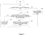
- step S11 whether the high voltage battery fails or not is determined. If the high voltage battery is determined to be faulty, step S12 is performed; otherwise, if the high voltage battery is determined to be normal, step S13 is performed.
- step S12 the low voltage electronic controller of the auxiliary electronic controller operates in the rotation speed closed loop mode. And then the method returns to step S11 to start a next round of determination.
- step S13 whether the state of charge of the low voltage storage battery 4 is lower than the first preset value is determined. If the state of charge of the low voltage storage battery 4 is lower than the first preset value, step S14 is performed; otherwise, if the state of charge of the low voltage storage battery 4 is not lower than the first preset value, step S15 is performed.
- step S14 the low voltage electronic controller of the auxiliary electronic controller operates in the torque control mode to charge the low voltage storage battery 4. And then the method returns to step S11 to start a next round of determination.
- step S15 the low voltage electronic controller of the auxiliary electronic controller exits the torque control mode, and then the method returns to step S11 to start the next round of determination.
- the low voltage of the auxiliary electronic controller stops running in the torque control mode, such that the low voltage storage battery 4 can avoid being overcharged.
- a still further control method based on any one of the above method embodiments is provided.
- a hysteresis range is set for the step of determining whether the state of charge of the low voltage storage battery 4 satisfies a requirement.
- the control method includes steps S1 to S6.
- step S1 whether the high voltage battery fails or not is determined. If the high voltage battery is determined to be faulty, step S2 is performed; otherwise, if the high voltage battery is determined to be normal, step S3 is performed.
- step S2 the low voltage electronic controller of the auxiliary electronic controller operates in the rotation speed closed loop mode. And then the control method returns to step S1 to start a next round of determination.
- step S3 whether the state of charge of the low voltage storage battery 4 is lower than a first preset value is determined. If the state of charge of the low voltage storage battery 4 is lower than the first preset value, step S4 is performed, otherwise, step S5 is performed.
- step S4 the low voltage electronic controller of the auxiliary electronic controller operates in the torque control mode to charge the low voltage storage battery 4. And then the control method returns to step S1 to start a next round of determination.
- step S5 whether the state of charge of the low voltage storage battery 4 is higher than a second preset value is determined.
- Step S6 is performed in case of a positive determination, otherwise, the control method returns to step S1.
- step S6 the low voltage electronic controller of the auxiliary electronic controller exits the torque control mode, and then the control method returns to step S11 to start a next round of determination.
- the low voltage winding of the auxiliary drive motor and the low voltage electronic controller that matches the low voltage winding are added, while omitting a DC/DC converter when compared with the topological structure as shown in Figure 1 .
- the low voltage winding and the low voltage electronic controller are powered by the low voltage storage battery.
- the low voltage electronic controller has two control modes, one is the rotation speed closed loop mode which ensures the auxiliary drive motor to operate constantly by rotating at a constant speed when the high voltage battery fails; the other is the torque control mode in which the low voltage storage battery is charged when the high voltage battery is normal.
- control system descripted above are only for illustrative purposes, the units described as separate parts may or may not be physically separate, and elements described as units may or may not be physical units, said elements may be located in one position, or may be distributed on a plurality of network units. Some or all of the units may be selected according to actual requirements to achieve the objectives of the solutions of the embodiments. Those skilled in the art can understand and perform the above technical solution without any creative work.
Landscapes
- Engineering & Computer Science (AREA)
- Power Engineering (AREA)
- Transportation (AREA)
- Mechanical Engineering (AREA)
- Life Sciences & Earth Sciences (AREA)
- Sustainable Development (AREA)
- Sustainable Energy (AREA)
- Electric Propulsion And Braking For Vehicles (AREA)
Abstract
Description
- The present disclosure relates to the field of electric vehicle technology, particularly to a power system of an electric vehicle, a control method, and an electric vehicle.
- As illustrated in
Figure 1 , conventional electric vehicle power system mainly includes ahigh voltage battery 1, a main drive motor and an electronic controller for themain drive motor 2, an auxiliary drive motor and an electronic controller for theauxiliary drive motor 3. The electronic controller is a motor drive and control system that is connected between a battery and a motor. The main drive motor and electronic controller for the main drive motor refers to the main drive motor and the electronic controller that matches the main drive motor, and the auxiliary drive motor and electronic control refers to the auxiliary drive motor and the electronic controller that matches the auxiliary drive motor. The main drive motor and the electronic controller therefor, and the auxiliary drive motor and the electronic controller therefor are both powered by thehigh voltage battery 1. In addition, the whole vehicle also includes a lowvoltage storage battery 4 to supply power to low voltage loads, and thehigh voltage battery 1 charges the lowvoltage storage battery 4 through a DC/DC converter 5. - In the topological structure illustrated in
Figure 1 , once thehigh voltage battery 1 fails, the auxiliary drive motor and electronic controller therefor 3 will stop running instantly, resulting in a great safety risk. Taking two sets of auxiliary drive motors and electronic controllers therefor, including an oil pump motor and an electronic controller for the oil pump motor, and an air pump motor and electronic controller for the air pump motor as an example, it may cause a difficulty in vehicle steering in a case that the oil pump motor and/or the electronic controller therefor stop running, and it may cause a vehicle brake failure in a case that the air pump motor and/or electronic controller therefor stop running. This is a great threat to personal safety of passengers and drivers on the vehicle. - In view of above, a power system of an electric vehicle, a control method, and an electric vehicle are provided according to the present disclosure to improve the topological structure illustrated in
Figure 1 , so as to avoid an instantaneous stopping of an auxiliary drive motor and an electronic controller for the auxiliary drive motor when a high voltage battery fails. - A power system of an electric vehicle includes a high voltage battery, a low voltage storage battery, a main drive motor and electronic controller for the main drive motor, and an auxiliary drive motor and electronic controller for the auxiliary drive motor, where,
the main drive motor and electronic controller for the main drive motor is powered by the high voltage battery;
the auxiliary drive motor includes a high voltage winding and a low voltage winding, the electronic controller of the auxiliary drive motor includes a high voltage electronic controller and a low voltage electronic controller, the high voltage battery and the high voltage winding of the auxiliary drive motor are connected via the high voltage electronic controller of the auxiliary drive motor, and the low voltage storage battery and the low voltage winding of the auxiliary drive motor are connected via the low voltage electronic controller of the auxiliary drive motor; and
the low voltage electronic controller of the auxiliary drive motor is configured to;
operate in a rotation speed closed loop mode in response to determining that the high voltage battery fails, and
operate in a torque control mode to charge the low voltage storage battery in response to determining that the high voltage battery is normal and state of charge of the low voltage storage battery is lower than a first preset value. - Optionally, the low voltage electronic controller of the auxiliary drive motor may further be configured to stop the torque control mode in response to determining that the high voltage battery is normal and the state of charge of the low voltage storage battery is not lower than the first preset value.
- Optionally, the low voltage electronic controller of the auxiliary drive motor may further be configured to stop the torque control mode in response to determining that the high voltage battery is normal and the state of charge of the low voltage is higher than a second preset value, where the second preset value is greater than the first preset value.
- Optionally, the low voltage electronic controller of the auxiliary drive motor may be configured to determine that the high voltage battery fails in response to determining that an output voltage of the high voltage battery is out of a preset range.
- Optionally, the power system of the electric vehicle may include two sets of the auxiliary drive motors and the electronic controller for the auxiliary drive motors, including a set of oil pump motor and electronic controller for the oil pump motor and a set of air pump motor and electronic controller for the air pump motor, where the two sets of the auxiliary drive motors and the electronic controllers for the auxiliary drive motors operate independently.
- An electric vehicle includes any one of the power systems of the electric vehicle described above.
- A method for controlling a power system of an electric vehicle, where the power system of the electric vehicle includes a high voltage battery, a low voltage storage battery, a main drive motor and an electronic controller for the main drive motor, and an auxiliary drive motor and an electronic controller for the auxiliary drive motor, where the main drive motor and the electronic controller for the main drive motor is powered by the high voltage battery; the auxiliary drive motor includes a high voltage winding and a low voltage winding; where the electronic controller of the auxiliary drive motor includes a high voltage electronic controller and a low voltage electronic controller, where the high voltage battery and the high voltage winding of the auxiliary drive motor are connected via the high voltage electronic controller of the auxiliary drive motor, and the low voltage storage battery and the low voltage winding of the auxiliary drive motor are connected via the low voltage electronic controller of the auxiliary drive motor;
the method includes: - determining whether the high voltage battery fails or not;
- controlling the low voltage controller of the auxiliary drive motor to operate in a rotation speed closed loop mode in response to determining that the high voltage battery fails;
- determining whether state of charge of the low voltage storage battery is lower than a first preset value in response to determining that the high voltage battery is normal; and
- controlling the low voltage controller of the auxiliary drive motor to operate in a torque control mode to charge the low voltage storage battery in response to determining that the state of charge battery of the low voltage storage battery is lower than the first preset value.
- Optionally, after the determining whether the state of charge of the low voltage storage battery is lower than the first preset value, the control method may further include:
stopping the torque control mode in response to determining that the state of charge of the low voltage storage battery is not lower than the first preset value. - Optionally, the determining whether the high voltage battery fails or not may include:
determining whether an output voltage of the high voltage battery is out of a preset range, and determining that the high voltage battery fails in case of a positive determination. - Optionally, the power system of the electric vehicle may include two sets of the auxiliary drive motors and the electronic controllers for the auxiliary drive motors, including a set of oil pump motor and electronic controller for the oil pump motor and a set of air pump motor and electronic controller for the air pump motor, where the two sets of the auxiliary drive motors and the electronic controllers for the auxiliary drive motors operate independently.
- According to the above technical solution of the present disclosure, the low voltage winding of the auxiliary drive motor and the low voltage electronic controller that matches the low voltage winding are added, while omitting a DC/DC converter when compared with the topological structure as shown in
Figure 1 . The low voltage winding and the low voltage electronic controller are powered by the low voltage storage battery. The low voltage electronic controller has two control modes, one is the rotation speed closed loop mode which ensures the auxiliary drive motor to operate constantly by rotating at a constant speed when the high voltage battery fails; the other is the torque control mode in which the low voltage storage battery is charged when the high voltage battery is normal. - The above description is merely a brief description of the technical solution according to the present disclosure. For the purpose of a clear description of the above and other objectives, features and advantages of this disclosure and a clear understanding of the technical means of the present disclosure, embodiments of the present disclosure are described hereinafter, such that the solution can be implemented in accordance with the contents of the specification.
- According to the description of the embodiments, various advantages and technical effects will become apparent to those skilled in the art. The drawings are only for the purpose of illustrating the embodiments and are not intended to limit this disclosure. Throughout the drawings, the same reference numerals refer to the same elements.
-
Figure 1 is a structural schematic diagram of a related power system of an electric vehicle; -
Figure 2 is a structural schematic diagram of a power system of an electric vehicle according to an embodiment of the present disclosure; -
Figure 3 is a schematic diagram of a controller area network, CAN, bus adapted to the power system of the electric vehicle inFigure 2 ; -
Figure 4 is a flow chart of a method for controlling a power system of an electric vehicle according to an embodiment of the present disclosure; -
Figure 5 is another flow chart of a control method for a power system of an electric vehicle according to an embodiment of the present disclosure; and -
Figure 6 is still another flow chart of a control method for a power system of an electric vehicle according to an embodiment of the present disclosure. - Hereinafter, the technical solution according to embodiments of the present disclosure will be described clearly and fully in conjunction with the drawings. Apparently, the described embodiments are only some rather than all embodiments according to the present disclosure. Various embodiments can be obtained by those skilled in the art based on the embodiments in the present disclosure without any creative work.
- In a topological structure illustrated in
Figure 1 , a main drive motor and electronic controller therefor and an auxiliary drive motor and electronic controller therefor are both powered by ahigh voltage battery 1. It can be known that both the main drive motor and the auxiliary drive motor inFigure 1 only have high voltage windings, and the electronic controllers of the two motors are high voltage electronic controllers that match the high voltage windings respectively. According to an embodiment of the present disclosure, a novel power system of an electric vehicle whose topological structure illustrated inFigure 2 is provided on the basis of the topological structure illustrated inFigure 1 . Compared with the topological structure ofFigure 1 , a low voltage winding of an auxiliary drive motor and an electronic controller that matches the low voltage winding are added and the DC/DC converter 5 is omitted in the topological structure ofFigure 2 . - As shown in
Figure 2 , the topological structure includes ahigh voltage battery 1, a lowvoltage storage battery 4, a main drive motor and an electronic controller for themain drive motor 2, and an auxiliary drive motor and an electronic controller for theauxiliary drive motor 6 after improvement. - The main drive motor and the electronic controller therefor 2 is powered by the
high voltage battery 1, which means that the main drive motor in the main drive motor and the electronic controller therefor 2 only has a high voltage winding. The electronic controller of the main drive motor connects thehigh voltage battery 1 and the high voltage winding of the main drive motor; - In the auxiliary drive motor and the electronic controller therefor 6, the auxiliary drive motor includes a high voltage winding and a low voltage winding, and the electronic controller for the auxiliary drive motor includes a high voltage electronic controller and a low voltage electronic controller. The high voltage electronic controller of the auxiliary drive motor is an electronic controller for connecting the
high voltage battery 1 and the high voltage winding of the auxiliary drive motor, and the low voltage electronic controller of the auxiliary drive motor is an electronic controller for connecting the lowvoltage storage battery 2 and the low voltage winding of the auxiliary drive motor. - The low voltage electronic controller of the auxiliary drive motor is configured to operate in a rotation speed closed loop mode when determining that the
high voltage battery 1 fails, and to operate in a torque control mode to charge the lowvoltage storage battery 4 when thehigh voltage battery 1 is normal and state of charge, SOC, of the lowvoltage storage battery 4 is lower than a first preset value. - The working principle of the topological structure in
Figure 2 is described hereinafter. - A power supply manner and a control mode of the main drive motor and the
electronic controller 2 are the same with those of the topological structure illustrated inFigure 1 , which are not repeated herein. - The high voltage winding and low voltage winding of the auxiliary drive motor are respectively oriented in different rotating coordinate systems, each of which is independently controlled by a set of electronic controller. The high voltage winding is controlled by the high voltage electronic controller, and the low voltage winding is controlled by the low voltage electronic controller. A power supply manner and a control mode of the high voltage winding of the auxiliary drive motor are the same as those of the topological structure illustrated in
Figure 1 . The high voltage winding of the auxiliary drive motor is powered by thehigh voltage battery 1, and the high voltage electronic controller operated in the rotation speed closed loop mode. The low voltage winding of the auxiliary drive motor is powered by the lowvoltage storage battery 4, and the low voltage electronic controller has two control modes described below. - One control mode is the rotation speed closed loop mode, said rotation speed closed loop mode is adopted only when the
high voltage battery 1 fails. Specifically, when thehigh voltage battery 1 fails, both the high voltage electronic controller of the auxiliary drive motor and the electronic controller of the main drive motor stop operating. The auxiliary drive motor runs in an electric motoring state under the rotation speed closed loop control of the low voltage electronic controller (that is, the low voltage electric controller is configured to convert electric energy of the lowvoltage storage battery 4 into mechanical energy of the auxiliary drive motor), such that the auxiliary drive motor can still operate constantly by rotating at a constant speed to avoid a safety risk when thehigh voltage battery 1 fails. - The other control mode is the torque control mode, said torque control mode is adopted only when the
high voltage battery 1 is normal and the state of charge of the lowvoltage storage battery 4 is lower than the first preset value. Specifically, when thehigh voltage battery 1 is normal and the lowvoltage storage battery 4 needs to be charged, the auxiliary drive motor operates constantly by rotating at a constant speed under the rotation speed closed loop control of the high voltage electronic controller, which means that the high voltage electronic controller is configured to convert the electric energy of the highvoltage storage battery 4 into the mechanical energy of the auxiliary drive motor. Meanwhile, the low voltage controller operates in the torque control mode, and a torque value of the low voltage controller is obtained by dividing a charging power required by the lowvoltage storage battery 4 by a current rotation speed of the auxiliary drive motor and then multiplying by a coefficient. The torque value is a negative value. For the low voltage electronic controller and the low voltage winding of the auxiliary drive motor, the torque value is for power generation. The low voltage electronic controller can convert the mechanical energy of the auxiliary drive motor into a direct current to charge the lowvoltage storage battery 4, such that the state of charge of the lowvoltage storage battery 4 can always be kept in a reasonable range. - Optionally, the low voltage electronic controller no longer operates in the torque control mode when the state of charge of the low
voltage storage battery 4 is charged to be not lower than the first preset value (for example, the low voltage storage battery is fully charged), so as to avoid overcharging the lowvoltage storage battery 4. In such case, the low voltage electronic controller does not operate in any one of the two control modes. - Optionally, in order to avoid the low voltage electronic controller from frequently entering and exiting the torque control mode due to a frequent fluctuation of the state of charge of the low
voltage storage battery 4 near the first preset value, according to an embodiment of the present disclosure, a hysteresis range is set when determining whether the state of charge of the lowvoltage storage battery 4 satisfies the requirement. When the state of charge of the lowvoltage storage battery 4 is lower than the first preset value, the low voltage electronic controller operates in the torque control mode, and when the low voltage storage battery is charged until the state of charge of the lowvoltage storage battery 4 is higher than a second preset value, the low voltage electronic controller exits the torque control mode, where the second preset value is greater than the first preset value. - The failure of the
high voltage battery 1 according to the embodiment includes a disconnection of an output circuit of thehigh voltage battery 1 due to an internal fault or other fault of thehigh voltage battery 1. The determining whether thehigh voltage battery 1 fails or not may be performed by, for example, determining whether an output voltage of thehigh voltage battery 1 is lower than a third preset value. Thehigh voltage battery 1 is determined to have a fault in case of a positive determination, and otherwise, thehigh voltage battery 1 is determined to be normal. - The high voltage electronic controller of the auxiliary drive motor, the low voltage electronic controller of the auxiliary drive motor, and the electronic controller of the main drive motor communicate with each other to transmit corresponding data information. For example, the electronic controller of the main drive motor transmits the output voltage of the
high voltage battery 1 to the low voltage electronic controller of the auxiliary drive motor. The communication mode includes, but not limited to, CAN bus communication. InFigure 3 , the CAN bus communication is used as an example. - Generally, the power system of the electric vehicle includes two sets of auxiliary drive motors and electronic controllers for the
auxiliary drive motors 6, where one set includes an oil pump motor and an electronic controller for oil pump motor, and the other set includes an air pump motor and an electronic controller for the air pump motor. The two sets of auxiliary drive motors and the electronic controllers therefor operate independently, such that a vehicle brake and a power-assisted steering system can continue working in a case that thehigh voltage battery 1 fails, and the vehicle can be decelerated and parked at roadside to ensure personal safety. - In view of above, according to the above technical solution of the present disclosure, the low voltage winding of the auxiliary drive motor and the low voltage electronic controller that matches the low voltage winding are added, while omitting a DC/DC converter when compared with the topological structure as shown in
Figure 1 . The low voltage winding and the low voltage electronic controller are powered by the low voltage storage battery. The low voltage electronic controller has two control modes, one is the rotation speed closed loop mode which ensures the auxiliary drive motor to operate constantly by rotating at a constant speed when the high voltage battery fails; the other is the torque control mode in which the low voltage storage battery is charged when the high voltage battery is normal.. - In addition, according to an embodiment of the present disclosure, an electronic vehicle including any one of the power systems of the electronic vehicle described earlier is provided, so as to avoid an instantaneous stopping of the auxiliary drive motor and the electronic controller therefor when the high voltage battery fails.
- According an embodiment of the present disclosure, a method for controlling a power system of an electric vehicle is provided. As illustrated in
Figure 2 , the power system of the electric vehicle includes ahigh voltage battery 1, a lowvoltage storage battery 4, a main drive motor and an electronic controller for themain drive motor 2, and an auxiliary drive motor and an electronic controller for theauxiliary drive motor 6. The main drive motor and the electronic controller therefor 2 is powered by thehigh voltage battery 1. n the auxiliary drive motor and the electronic controller therefor 6, the auxiliary drive motor includes a high voltage winding and a low voltage winding, and the electronic controller of the auxiliary drive motor includes a high voltage electronic controller and a low voltage electronic controller. The high voltage electronic controller of the auxiliary drive motor is an electronic controller for connecting thehigh voltage battery 1 and the high voltage winding of the auxiliary drive motor, and the low voltage electronic controller of the auxiliary drive motor is an electronic controller for connecting the lowvoltage storage battery 2 and the low voltage winding of the auxiliary drive motor. Generally, the power system of the electric vehicle includes two sets of auxiliary drive motors and electronic controllers for the auxiliary drive motors, where one set includes an oil pump motor and an electronic controller for the oil pump motor, and the other set includes an air pump motor and an electronic controller for the air pump motor. The two sets of auxiliary drive motors and the electronic controllers for the auxiliary drive motors operate independently. - The method is applied to the low voltage electronic controller of the auxiliary drive motor. As illustrated in
Figure 4 , the method includes steps S01 to S04. - In step S01, whether the high voltage battery fails or not is determined. If the high voltage battery is determined to be faulty, step S02 is performed; otherwise, if the high voltage battery is determined to be normal, step S03 is performed.
- The determining whether the
high voltage battery 1 fails or not may include determining whether an output voltage of thehigh voltage battery 1 is out of a preset range. Thehigh voltage battery 1 is determined to have a fault in case of a positive determination, and otherwise, thehigh voltage battery 1 is determined to be normal. - In step S02, the low voltage electronic controller of the auxiliary electronic controller operates in a rotation speed closed loop mode. When operating in this mode, the method returns to step S01 to start a next round of determination.
- In step S03, whether the state of charge of the low
voltage storage battery 4 is lower than a first preset value is determined. If the state of charge of the lowvoltage storage battery 4 is lower than the first preset value, step S04 is performed; otherwise, the method returns to step S01 to start a next round of determination. - In step S04, the low voltage electronic controller of the auxiliary electronic controller operates in a torque control mode to charge the low
voltage storage battery 4. When operating in this mode, the method returns to step S01 to start a next round of determination. - In addition, according to an embodiment of the present disclosure, a control method including steps S11 to S15 as illustrated in
Figure 5 is further provided. - In step S11, whether the high voltage battery fails or not is determined. If the high voltage battery is determined to be faulty, step S12 is performed; otherwise, if the high voltage battery is determined to be normal, step S13 is performed.
- In step S12, the low voltage electronic controller of the auxiliary electronic controller operates in the rotation speed closed loop mode. And then the method returns to step S11 to start a next round of determination.
- In step S13, whether the state of charge of the low
voltage storage battery 4 is lower than the first preset value is determined. If the state of charge of the lowvoltage storage battery 4 is lower than the first preset value, step S14 is performed; otherwise, if the state of charge of the lowvoltage storage battery 4 is not lower than the first preset value, step S15 is performed. - In step S14, the low voltage electronic controller of the auxiliary electronic controller operates in the torque control mode to charge the low
voltage storage battery 4. And then the method returns to step S11 to start a next round of determination. - In step S15, the low voltage electronic controller of the auxiliary electronic controller exits the torque control mode, and then the method returns to step S11 to start the next round of determination.
- Compared with the technical solution illustrated in
Figure 4 , in the technical solution illustrated inFigure 5 , when the state of charge of the lowvoltage storage battery 4 is determined to be not lower than the first preset value, the low voltage of the auxiliary electronic controller stops running in the torque control mode, such that the lowvoltage storage battery 4 can avoid being overcharged. - Optionally, according to an embodiment of the present disclosure, in order to avoid the low voltage electronic controller from frequently entering and exiting the torque control mode due to a frequent fluctuation of the state of charge of the low
voltage storage battery 4 in vicinity of the first preset value, a still further control method based on any one of the above method embodiments is provided. In the control method, a hysteresis range is set for the step of determining whether the state of charge of the lowvoltage storage battery 4 satisfies a requirement. Correspondingly, as illustrated inFigure 6 , the control method includes steps S1 to S6. - In step S1, whether the high voltage battery fails or not is determined. If the high voltage battery is determined to be faulty, step S2 is performed; otherwise, if the high voltage battery is determined to be normal, step S3 is performed.
- In step S2, the low voltage electronic controller of the auxiliary electronic controller operates in the rotation speed closed loop mode. And then the control method returns to step S1 to start a next round of determination.
- In step S3, whether the state of charge of the low
voltage storage battery 4 is lower than a first preset value is determined. If the state of charge of the lowvoltage storage battery 4 is lower than the first preset value, step S4 is performed, otherwise, step S5 is performed. - In step S4, the low voltage electronic controller of the auxiliary electronic controller operates in the torque control mode to charge the low
voltage storage battery 4. And then the control method returns to step S1 to start a next round of determination. - In step S5, whether the state of charge of the low
voltage storage battery 4 is higher than a second preset value is determined. Step S6 is performed in case of a positive determination, otherwise, the control method returns to step S1. - In step S6, the low voltage electronic controller of the auxiliary electronic controller exits the torque control mode, and then the control method returns to step S11 to start a next round of determination.
- In view of above, according to the above technical solution of the present disclosure, the low voltage winding of the auxiliary drive motor and the low voltage electronic controller that matches the low voltage winding are added, while omitting a DC/DC converter when compared with the topological structure as shown in
Figure 1 . The low voltage winding and the low voltage electronic controller are powered by the low voltage storage battery. The low voltage electronic controller has two control modes, one is the rotation speed closed loop mode which ensures the auxiliary drive motor to operate constantly by rotating at a constant speed when the high voltage battery fails; the other is the torque control mode in which the low voltage storage battery is charged when the high voltage battery is normal. - It should be noted that the embodiments in this specification are all described in a progressive manner. Description of each of the embodiments focuses on differences from other embodiments, and reference may be made to each other for the same or similar parts among respective embodiments. The method embodiments are substantially similar to the apparatus embodiments and therefore are only briefly described, and reference may be made to the description of the power system of the electric vehicle for the associated part.
- The embodiments of the control system descripted above are only for illustrative purposes, the units described as separate parts may or may not be physically separate, and elements described as units may or may not be physical units, said elements may be located in one position, or may be distributed on a plurality of network units. Some or all of the units may be selected according to actual requirements to achieve the objectives of the solutions of the embodiments. Those skilled in the art can understand and perform the above technical solution without any creative work.
- It should be further noted that the relationship terminologies such as "first", "second" and the like are only used herein to distinguish one entity or operation from another, rather than to necessitate or imply that the actual relationship or order exists between the entities or operations. Furthermore, terms of "include", "comprise" or any other variants are intended to be non-exclusive. Therefore, a process, method, article or device including a plurality of elements includes not only the elements defined therein but also other elements that are not enumerated, or in addition, includes elements inherent for the process, method, article or device. Unless expressively limited otherwise, the statement "comprising (including) one..." does not exclude the case that other similar elements may be included in the process, method, article or device.
- The above description of examples according to the present disclosure is only intended to help those skilled in the art to implement and use the present disclosure. Various modifications and improvements that can be made to the embodiments of the present disclosure are obvious to those skilled in the art.
Claims (11)
- A power system of an electric vehicle, comprising:a high voltage battery (1),a low voltage storage battery (4),a main drive motor and an electronic controller for the main drive motor (2), andan auxiliary drive motor and an electronic controller for the auxiliary drive motor (6),wherein the main drive motor and the electronic controller for the main drive motor (2) is powered by the high voltage battery (1);wherein the auxiliary drive motor comprises a high voltage winding and a low voltage winding;wherein the electronic controller of the auxiliary drive motor comprises a high voltage electronic controller and a low voltage electronic controller, wherein the high voltage battery (1) and the high voltage winding of the auxiliary drive motor are connected via the high voltage electronic controller of the auxiliary drive motor, and the low voltage storage battery (4) and the low voltage winding of the auxiliary drive motor are connected via the low voltage electronic controller of the auxiliary drive motor; andwherein the low voltage electronic controller of the auxiliary drive motor is configured to:operate in a rotation speed closed loop mode in response to determining that the high voltage battery fails, andoperate in a torque control mode to charge the low voltage storage battery (4) in response to determining that the high voltage battery is normal and a state of charge of the low voltage storage battery (4) is lower than a first preset value.
- The power system of the electric vehicle according to claim 1, wherein the low voltage electronic controller of the auxiliary drive motor is further configured to stop the torque control mode in response to determining that the high voltage battery is normal and the state of charge of the low voltage storage battery (4) is not lower than the first preset value.
- The power system of the electric vehicle according to claim 1, wherein the low voltage electronic controller of the auxiliary drive motor is further configured to stop the torque control mode in response to determining that the high voltage battery is normal and the state of charge of the low voltage is higher than a second preset value, wherein the second preset value is greater than the first preset value.
- The power system of the electric vehicle according to any one of claims 1 to 3, wherein the low voltage electronic controller of the auxiliary drive motor is configured to determine that the high voltage battery fails in response to determining that an output voltage of the high voltage battery is out of a preset range.
- The power system of the electric vehicle according to any one of claims 1 to 4, wherein the power system of the electric vehicle comprises two sets of the auxiliary drive motors and the electronic controllers for the auxiliary drive motors (6), including a set of oil pump motor and electronic controller for the oil pump motor and a set of air pump motor and electronic controller for the air pump motor, wherein the two sets of the auxiliary drive motors and electronic controllers for the auxiliary drive motors (6) operate independently.
- An electric vehicle, comprising the power system of the electric vehicle according to any one of claims 1 to 5.
- A method for controlling a power system of an electric vehicle, wherein the power system of the electric vehicle comprises a high voltage battery (1), a low voltage storage battery (4), a main drive motor and an electronic controller for the main drive motor (2), and an auxiliary drive motor and an electronic controller for the auxiliary drive motor (6), wherein the main drive motor and the electronic controller for the main drive motor (2) is powered by the high voltage battery (1); wherein the auxiliary drive motor comprises a high voltage winding and a low voltage winding; wherein the electronic controller of the auxiliary drive motor comprises a high voltage electronic controller and a low voltage electronic controller, wherein the high voltage battery (1) and the high voltage winding of the auxiliary drive motor are connected via the high voltage electronic controller of the auxiliary drive motor, and the low voltage storage battery (4) and the low voltage winding of the auxiliary drive motor are connected via the low voltage electronic controller of the auxiliary drive motor;
the method comprises:determining (S01, S11, S1) whether the high voltage battery (1) fails or not;controlling (S02, S12, S2) the low voltage controller of the auxiliary drive motor to operate in a rotation speed closed loop mode in response to determining that the high voltage battery (1) fails;determining (S03, S13, S3) whether state of charge of the low voltage storage battery (4) is lower than a first preset value in response to determining that the high voltage battery (1) is normal; andcontrolling (S04, S14, S4) the low voltage controller of the auxiliary drive motor to operate in a torque control mode to charge the low voltage storage battery (4) in response to determining that the state of charge battery of the low voltage storage battery (4) is lower than the first preset value. - The method according to claim 7, wherein after the determining whether the state of charge of the low voltage storage battery (4) is lower than the first preset value, the method further comprises:
stopping (S15) the torque control mode in response to determining that the state of charge of the low voltage storage battery (4) is not lower than the first preset value. - The method according to claim 7, wherein after the determining whether the state of charge of the low voltage storage battery (4) is lower than the first preset value, the method further comprises:
stopping (6) the torque control mode in response to determining that the high voltage battery (1) is normal and the state of charge of the low voltage is higher than a second preset value, wherein the second preset value is greater than the first preset value. - The method according to any one of claims 7 to 9, wherein the determining whether the high voltage battery (1) fails or not comprises:determining whether an output voltage of the high voltage battery (1) is out of a preset range, anddetermining that the high voltage battery (1) fails in case of a positive determination.
- The method according to any one of claims 7 to 10, wherein the power system of the electric vehicle comprises two sets of the auxiliary drive motors and the electronic controllers for the auxiliary drive motors (6), including a set of oil pump motor and electronic controller for the oil pump motor and a set of air pump motor and electronic controller for the air pump motor, wherein the two sets of the auxiliary drive motors and the electronic controllers for the auxiliary drive motors (6) operate independently.
Applications Claiming Priority (1)
| Application Number | Priority Date | Filing Date | Title |
|---|---|---|---|
| CN201810757814.8A CN108859768B (en) | 2018-07-11 | 2018-07-11 | Electric automobile power system, control method and electric automobile |
Publications (3)
| Publication Number | Publication Date |
|---|---|
| EP3594046A1 true EP3594046A1 (en) | 2020-01-15 |
| EP3594046C0 EP3594046C0 (en) | 2023-08-16 |
| EP3594046B1 EP3594046B1 (en) | 2023-08-16 |
Family
ID=64301012
Family Applications (1)
| Application Number | Title | Priority Date | Filing Date |
|---|---|---|---|
| EP19184135.2A Active EP3594046B1 (en) | 2018-07-11 | 2019-07-03 | Power system of electric vehicle,control method and electric vehicle |
Country Status (3)
| Country | Link |
|---|---|
| US (1) | US10974600B2 (en) |
| EP (1) | EP3594046B1 (en) |
| CN (1) | CN108859768B (en) |
Cited By (2)
| Publication number | Priority date | Publication date | Assignee | Title |
|---|---|---|---|---|
| CN112224022A (en) * | 2020-09-09 | 2021-01-15 | 东风汽车集团有限公司 | Storage battery power supplementing method and system and readable storage medium |
| DE102023110856A1 (en) | 2023-04-27 | 2024-10-31 | Bayerische Motoren Werke Aktiengesellschaft | METHOD FOR OPERATING AN ELECTRIC VEHICLE AND ELECTRIC VEHICLE |
Families Citing this family (5)
| Publication number | Priority date | Publication date | Assignee | Title |
|---|---|---|---|---|
| CN110239366A (en) * | 2019-06-24 | 2019-09-17 | 黑龙江工程学院 | Energy control method for power system of extended-range electric vehicle |
| CN113335132A (en) * | 2020-03-03 | 2021-09-03 | 北京新能源汽车股份有限公司 | Control method, control device and control equipment for electric automobile |
| CN113085879B (en) * | 2021-04-02 | 2022-09-13 | 北京车和家信息技术有限公司 | Vehicle control method, device, storage medium, electronic device, and vehicle |
| CN117360611A (en) * | 2023-11-22 | 2024-01-09 | 一汽解放汽车有限公司 | A control method and control system for a new energy dual-source steering oil pump |
| CN118833062A (en) * | 2024-07-23 | 2024-10-25 | 东风商用车有限公司 | Air compressor redundancy system based on functional safety and air compressor control method |
Citations (4)
| Publication number | Priority date | Publication date | Assignee | Title |
|---|---|---|---|---|
| EP1947759A2 (en) * | 2005-10-10 | 2008-07-23 | Lei He | An starting and generating multiplying control system, and a method for using the system, and an electromotion mixed dynamic vehicle which uses the system and the method |
| US20090033253A1 (en) * | 2007-07-30 | 2009-02-05 | Gm Global Technology Operations, Inc. | Electric traction system for a vehicle having a dual winding ac traction motor |
| US20100006360A1 (en) * | 2008-07-11 | 2010-01-14 | Toyota Jidosha Kabushiki Kaisha | Control system and method for hybrid vehicle |
| EP2873551A2 (en) * | 2013-11-15 | 2015-05-20 | LG Electronics Inc. | Driving apparatus for electric vehicle |
Family Cites Families (7)
| Publication number | Priority date | Publication date | Assignee | Title |
|---|---|---|---|---|
| JP3094745B2 (en) * | 1993-09-24 | 2000-10-03 | トヨタ自動車株式会社 | Hybrid vehicle power generation control device |
| CN105584520B (en) | 2014-11-17 | 2018-09-11 | 比亚迪股份有限公司 | The steering power system and its control method of electric vehicle |
| JP6237665B2 (en) * | 2015-02-10 | 2017-11-29 | トヨタ自動車株式会社 | Hybrid car |
| CN106965701B (en) * | 2017-04-28 | 2024-07-12 | 南京颐创科技发展有限公司 | Emergency starting system and electric automobile emergency starting device |
| CN107472030B (en) * | 2017-06-09 | 2020-07-24 | 北汽福田汽车股份有限公司 | Control method and system of electric automobile and vehicle |
| CN107618565B (en) * | 2017-09-22 | 2020-01-10 | 厦门金龙联合汽车工业有限公司 | Switching control method of dual-source emergency electric power steering system |
| CN108099636B (en) * | 2017-11-23 | 2021-04-06 | 朱颖 | Device and method for balancing and protecting battery pack |
-
2018
- 2018-07-11 CN CN201810757814.8A patent/CN108859768B/en active Active
-
2019
- 2019-07-03 EP EP19184135.2A patent/EP3594046B1/en active Active
- 2019-07-09 US US16/506,691 patent/US10974600B2/en active Active
Patent Citations (4)
| Publication number | Priority date | Publication date | Assignee | Title |
|---|---|---|---|---|
| EP1947759A2 (en) * | 2005-10-10 | 2008-07-23 | Lei He | An starting and generating multiplying control system, and a method for using the system, and an electromotion mixed dynamic vehicle which uses the system and the method |
| US20090033253A1 (en) * | 2007-07-30 | 2009-02-05 | Gm Global Technology Operations, Inc. | Electric traction system for a vehicle having a dual winding ac traction motor |
| US20100006360A1 (en) * | 2008-07-11 | 2010-01-14 | Toyota Jidosha Kabushiki Kaisha | Control system and method for hybrid vehicle |
| EP2873551A2 (en) * | 2013-11-15 | 2015-05-20 | LG Electronics Inc. | Driving apparatus for electric vehicle |
Cited By (3)
| Publication number | Priority date | Publication date | Assignee | Title |
|---|---|---|---|---|
| CN112224022A (en) * | 2020-09-09 | 2021-01-15 | 东风汽车集团有限公司 | Storage battery power supplementing method and system and readable storage medium |
| DE102023110856A1 (en) | 2023-04-27 | 2024-10-31 | Bayerische Motoren Werke Aktiengesellschaft | METHOD FOR OPERATING AN ELECTRIC VEHICLE AND ELECTRIC VEHICLE |
| WO2024223152A1 (en) | 2023-04-27 | 2024-10-31 | Bayerische Motoren Werke Aktiengesellschaft | Method for operating an electric vehicle, and electric vehicle |
Also Published As
| Publication number | Publication date |
|---|---|
| EP3594046C0 (en) | 2023-08-16 |
| EP3594046B1 (en) | 2023-08-16 |
| US20200016982A1 (en) | 2020-01-16 |
| CN108859768A (en) | 2018-11-23 |
| US10974600B2 (en) | 2021-04-13 |
| CN108859768B (en) | 2020-08-28 |
Similar Documents
| Publication | Publication Date | Title |
|---|---|---|
| EP3594046B1 (en) | Power system of electric vehicle,control method and electric vehicle | |
| EP2802891B1 (en) | System and method for high voltage cable detection in hybrid vehicles | |
| CN111319467B (en) | Vehicle Power System | |
| CN110606074B (en) | Limping control method of 48V hybrid vehicle | |
| EP3612847B1 (en) | Vehicle and control method thereof and system | |
| EP2817645B1 (en) | High voltage cable detection using rotating machine in hybrid vehicles | |
| KR101551086B1 (en) | Emergency Power supply system using fuelcell | |
| JP2016510706A (en) | Operation method and arrangement of hybrid electric vehicle | |
| JP2019088141A (en) | Electric power system for vehicle | |
| JP6673046B2 (en) | Power supply system for electric vehicles | |
| KR20150008378A (en) | Isolation contactor transition polarity control | |
| KR102400606B1 (en) | Energy regeneration system and method for ship | |
| JP2018027733A (en) | Charge controller of hybrid vehicle | |
| KR101854017B1 (en) | Power supplying device of motor-generator for mild hybrid vehicle and controlling method thferof | |
| KR102522606B1 (en) | Apparatus and method for protecting inverter in hybrid vehicle from overvoltage | |
| US20250135922A1 (en) | Multi-input charging device and method | |
| US20260112899A1 (en) | Power supply system | |
| JP2005137107A (en) | Hybrid vehicle start-up control apparatus and method | |
| JP7679799B2 (en) | Vehicle control device | |
| CN114256946B (en) | Power supply management system and power supply management method | |
| CN111660812B (en) | Power supply system of extended range vehicle and control method thereof | |
| US20260034889A1 (en) | Control device for battery electric vehicle | |
| JP2017100661A (en) | Electric-vehicular control apparatus | |
| KR101823076B1 (en) | Integrated starter generator system and controlling method thereof | |
| WO2023073975A1 (en) | Battery power source circuit |
Legal Events
| Date | Code | Title | Description |
|---|---|---|---|
| PUAI | Public reference made under article 153(3) epc to a published international application that has entered the european phase |
Free format text: ORIGINAL CODE: 0009012 |
|
| STAA | Information on the status of an ep patent application or granted ep patent |
Free format text: STATUS: THE APPLICATION HAS BEEN PUBLISHED |
|
| AK | Designated contracting states |
Kind code of ref document: A1 Designated state(s): AL AT BE BG CH CY CZ DE DK EE ES FI FR GB GR HR HU IE IS IT LI LT LU LV MC MK MT NL NO PL PT RO RS SE SI SK SM TR |
|
| AX | Request for extension of the european patent |
Extension state: BA ME |
|
| STAA | Information on the status of an ep patent application or granted ep patent |
Free format text: STATUS: REQUEST FOR EXAMINATION WAS MADE |
|
| 17P | Request for examination filed |
Effective date: 20200715 |
|
| RBV | Designated contracting states (corrected) |
Designated state(s): AL AT BE BG CH CY CZ DE DK EE ES FI FR GB GR HR HU IE IS IT LI LT LU LV MC MK MT NL NO PL PT RO RS SE SI SK SM TR |
|
| STAA | Information on the status of an ep patent application or granted ep patent |
Free format text: STATUS: EXAMINATION IS IN PROGRESS |
|
| 17Q | First examination report despatched |
Effective date: 20210720 |
|
| GRAP | Despatch of communication of intention to grant a patent |
Free format text: ORIGINAL CODE: EPIDOSNIGR1 |
|
| STAA | Information on the status of an ep patent application or granted ep patent |
Free format text: STATUS: GRANT OF PATENT IS INTENDED |
|
| INTG | Intention to grant announced |
Effective date: 20230301 |
|
| GRAS | Grant fee paid |
Free format text: ORIGINAL CODE: EPIDOSNIGR3 |
|
| GRAA | (expected) grant |
Free format text: ORIGINAL CODE: 0009210 |
|
| STAA | Information on the status of an ep patent application or granted ep patent |
Free format text: STATUS: THE PATENT HAS BEEN GRANTED |
|
| AK | Designated contracting states |
Kind code of ref document: B1 Designated state(s): AL AT BE BG CH CY CZ DE DK EE ES FI FR GB GR HR HU IE IS IT LI LT LU LV MC MK MT NL NO PL PT RO RS SE SI SK SM TR |
|
| REG | Reference to a national code |
Ref country code: CH Ref legal event code: EP |
|
| REG | Reference to a national code |
Ref country code: DE Ref legal event code: R096 Ref document number: 602019034966 Country of ref document: DE |
|
| REG | Reference to a national code |
Ref country code: IE Ref legal event code: FG4D |
|
| U01 | Request for unitary effect filed |
Effective date: 20230823 |
|
| U07 | Unitary effect registered |
Designated state(s): AT BE BG DE DK EE FI FR IT LT LU LV MT NL PT SE SI Effective date: 20230830 |
|
| PG25 | Lapsed in a contracting state [announced via postgrant information from national office to epo] |
Ref country code: GR Free format text: LAPSE BECAUSE OF FAILURE TO SUBMIT A TRANSLATION OF THE DESCRIPTION OR TO PAY THE FEE WITHIN THE PRESCRIBED TIME-LIMIT Effective date: 20231117 |
|
| PG25 | Lapsed in a contracting state [announced via postgrant information from national office to epo] |
Ref country code: IS Free format text: LAPSE BECAUSE OF FAILURE TO SUBMIT A TRANSLATION OF THE DESCRIPTION OR TO PAY THE FEE WITHIN THE PRESCRIBED TIME-LIMIT Effective date: 20231216 |
|
| PG25 | Lapsed in a contracting state [announced via postgrant information from national office to epo] |
Ref country code: RS Free format text: LAPSE BECAUSE OF FAILURE TO SUBMIT A TRANSLATION OF THE DESCRIPTION OR TO PAY THE FEE WITHIN THE PRESCRIBED TIME-LIMIT Effective date: 20230816 Ref country code: NO Free format text: LAPSE BECAUSE OF FAILURE TO SUBMIT A TRANSLATION OF THE DESCRIPTION OR TO PAY THE FEE WITHIN THE PRESCRIBED TIME-LIMIT Effective date: 20231116 Ref country code: IS Free format text: LAPSE BECAUSE OF FAILURE TO SUBMIT A TRANSLATION OF THE DESCRIPTION OR TO PAY THE FEE WITHIN THE PRESCRIBED TIME-LIMIT Effective date: 20231216 Ref country code: HR Free format text: LAPSE BECAUSE OF FAILURE TO SUBMIT A TRANSLATION OF THE DESCRIPTION OR TO PAY THE FEE WITHIN THE PRESCRIBED TIME-LIMIT Effective date: 20230816 Ref country code: GR Free format text: LAPSE BECAUSE OF FAILURE TO SUBMIT A TRANSLATION OF THE DESCRIPTION OR TO PAY THE FEE WITHIN THE PRESCRIBED TIME-LIMIT Effective date: 20231117 |
|
| PG25 | Lapsed in a contracting state [announced via postgrant information from national office to epo] |
Ref country code: PL Free format text: LAPSE BECAUSE OF FAILURE TO SUBMIT A TRANSLATION OF THE DESCRIPTION OR TO PAY THE FEE WITHIN THE PRESCRIBED TIME-LIMIT Effective date: 20230816 |
|
| PG25 | Lapsed in a contracting state [announced via postgrant information from national office to epo] |
Ref country code: ES Free format text: LAPSE BECAUSE OF FAILURE TO SUBMIT A TRANSLATION OF THE DESCRIPTION OR TO PAY THE FEE WITHIN THE PRESCRIBED TIME-LIMIT Effective date: 20230816 |
|
| PG25 | Lapsed in a contracting state [announced via postgrant information from national office to epo] |
Ref country code: SM Free format text: LAPSE BECAUSE OF FAILURE TO SUBMIT A TRANSLATION OF THE DESCRIPTION OR TO PAY THE FEE WITHIN THE PRESCRIBED TIME-LIMIT Effective date: 20230816 Ref country code: RO Free format text: LAPSE BECAUSE OF FAILURE TO SUBMIT A TRANSLATION OF THE DESCRIPTION OR TO PAY THE FEE WITHIN THE PRESCRIBED TIME-LIMIT Effective date: 20230816 Ref country code: ES Free format text: LAPSE BECAUSE OF FAILURE TO SUBMIT A TRANSLATION OF THE DESCRIPTION OR TO PAY THE FEE WITHIN THE PRESCRIBED TIME-LIMIT Effective date: 20230816 Ref country code: CZ Free format text: LAPSE BECAUSE OF FAILURE TO SUBMIT A TRANSLATION OF THE DESCRIPTION OR TO PAY THE FEE WITHIN THE PRESCRIBED TIME-LIMIT Effective date: 20230816 Ref country code: SK Free format text: LAPSE BECAUSE OF FAILURE TO SUBMIT A TRANSLATION OF THE DESCRIPTION OR TO PAY THE FEE WITHIN THE PRESCRIBED TIME-LIMIT Effective date: 20230816 |
|
| REG | Reference to a national code |
Ref country code: DE Ref legal event code: R097 Ref document number: 602019034966 Country of ref document: DE |
|
| PLBE | No opposition filed within time limit |
Free format text: ORIGINAL CODE: 0009261 |
|
| STAA | Information on the status of an ep patent application or granted ep patent |
Free format text: STATUS: NO OPPOSITION FILED WITHIN TIME LIMIT |
|
| 26N | No opposition filed |
Effective date: 20240517 |
|
| U20 | Renewal fee for the european patent with unitary effect paid |
Year of fee payment: 6 Effective date: 20240726 |
|
| PG25 | Lapsed in a contracting state [announced via postgrant information from national office to epo] |
Ref country code: MC Free format text: LAPSE BECAUSE OF FAILURE TO SUBMIT A TRANSLATION OF THE DESCRIPTION OR TO PAY THE FEE WITHIN THE PRESCRIBED TIME-LIMIT Effective date: 20230816 |
|
| REG | Reference to a national code |
Ref country code: CH Ref legal event code: PL |
|
| GBPC | Gb: european patent ceased through non-payment of renewal fee |
Effective date: 20240703 |
|
| PG25 | Lapsed in a contracting state [announced via postgrant information from national office to epo] |
Ref country code: CH Free format text: LAPSE BECAUSE OF NON-PAYMENT OF DUE FEES Effective date: 20240731 |
|
| PG25 | Lapsed in a contracting state [announced via postgrant information from national office to epo] |
Ref country code: GB Free format text: LAPSE BECAUSE OF NON-PAYMENT OF DUE FEES Effective date: 20240703 |
|
| PG25 | Lapsed in a contracting state [announced via postgrant information from national office to epo] |
Ref country code: IE Free format text: LAPSE BECAUSE OF NON-PAYMENT OF DUE FEES Effective date: 20240703 |
|
| U20 | Renewal fee for the european patent with unitary effect paid |
Year of fee payment: 7 Effective date: 20250721 |
|
| PG25 | Lapsed in a contracting state [announced via postgrant information from national office to epo] |
Ref country code: CY Free format text: LAPSE BECAUSE OF FAILURE TO SUBMIT A TRANSLATION OF THE DESCRIPTION OR TO PAY THE FEE WITHIN THE PRESCRIBED TIME-LIMIT; INVALID AB INITIO Effective date: 20190703 |
|
| PG25 | Lapsed in a contracting state [announced via postgrant information from national office to epo] |
Ref country code: HU Free format text: LAPSE BECAUSE OF FAILURE TO SUBMIT A TRANSLATION OF THE DESCRIPTION OR TO PAY THE FEE WITHIN THE PRESCRIBED TIME-LIMIT; INVALID AB INITIO Effective date: 20190703 |