EP3594025B1 - Pneumatic tire - Google Patents
Pneumatic tire Download PDFInfo
- Publication number
- EP3594025B1 EP3594025B1 EP19185307.6A EP19185307A EP3594025B1 EP 3594025 B1 EP3594025 B1 EP 3594025B1 EP 19185307 A EP19185307 A EP 19185307A EP 3594025 B1 EP3594025 B1 EP 3594025B1
- Authority
- EP
- European Patent Office
- Prior art keywords
- tire
- flange
- rim
- carcass
- clinch
- Prior art date
- Legal status (The legal status is an assumption and is not a legal conclusion. Google has not performed a legal analysis and makes no representation as to the accuracy of the status listed.)
- Active
Links
Images




Classifications
-
- B—PERFORMING OPERATIONS; TRANSPORTING
- B60—VEHICLES IN GENERAL
- B60C—VEHICLE TYRES; TYRE INFLATION; TYRE CHANGING; CONNECTING VALVES TO INFLATABLE ELASTIC BODIES IN GENERAL; DEVICES OR ARRANGEMENTS RELATED TO TYRES
- B60C13/00—Tyre sidewalls; Protecting, decorating, marking, or the like, thereof
-
- B—PERFORMING OPERATIONS; TRANSPORTING
- B60—VEHICLES IN GENERAL
- B60C—VEHICLE TYRES; TYRE INFLATION; TYRE CHANGING; CONNECTING VALVES TO INFLATABLE ELASTIC BODIES IN GENERAL; DEVICES OR ARRANGEMENTS RELATED TO TYRES
- B60C15/00—Tyre beads, e.g. ply turn-up or overlap
- B60C15/02—Seating or securing beads on rims
- B60C15/024—Bead contour, e.g. lips, grooves, or ribs
- B60C15/0242—Bead contour, e.g. lips, grooves, or ribs with bead extensions located radially outside the rim flange position, e.g. rim flange protectors
-
- B—PERFORMING OPERATIONS; TRANSPORTING
- B60—VEHICLES IN GENERAL
- B60C—VEHICLE TYRES; TYRE INFLATION; TYRE CHANGING; CONNECTING VALVES TO INFLATABLE ELASTIC BODIES IN GENERAL; DEVICES OR ARRANGEMENTS RELATED TO TYRES
- B60C15/00—Tyre beads, e.g. ply turn-up or overlap
- B60C15/0009—Tyre beads, e.g. ply turn-up or overlap features of the carcass terminal portion
- B60C15/0072—Tyre beads, e.g. ply turn-up or overlap features of the carcass terminal portion with ply reverse folding, i.e. carcass layer folded around the bead core from the outside to the inside
-
- B—PERFORMING OPERATIONS; TRANSPORTING
- B60—VEHICLES IN GENERAL
- B60C—VEHICLE TYRES; TYRE INFLATION; TYRE CHANGING; CONNECTING VALVES TO INFLATABLE ELASTIC BODIES IN GENERAL; DEVICES OR ARRANGEMENTS RELATED TO TYRES
- B60C15/00—Tyre beads, e.g. ply turn-up or overlap
- B60C15/0009—Tyre beads, e.g. ply turn-up or overlap features of the carcass terminal portion
-
- B—PERFORMING OPERATIONS; TRANSPORTING
- B60—VEHICLES IN GENERAL
- B60C—VEHICLE TYRES; TYRE INFLATION; TYRE CHANGING; CONNECTING VALVES TO INFLATABLE ELASTIC BODIES IN GENERAL; DEVICES OR ARRANGEMENTS RELATED TO TYRES
- B60C15/00—Tyre beads, e.g. ply turn-up or overlap
- B60C15/0009—Tyre beads, e.g. ply turn-up or overlap features of the carcass terminal portion
- B60C15/0036—Tyre beads, e.g. ply turn-up or overlap features of the carcass terminal portion with high ply turn-up, i.e. folded around the bead core and terminating radially above the point of maximum section width
- B60C15/0045—Tyre beads, e.g. ply turn-up or overlap features of the carcass terminal portion with high ply turn-up, i.e. folded around the bead core and terminating radially above the point of maximum section width with ply turn-up up to the belt edges, i.e. folded around the bead core and extending to the belt edges
-
- B—PERFORMING OPERATIONS; TRANSPORTING
- B60—VEHICLES IN GENERAL
- B60C—VEHICLE TYRES; TYRE INFLATION; TYRE CHANGING; CONNECTING VALVES TO INFLATABLE ELASTIC BODIES IN GENERAL; DEVICES OR ARRANGEMENTS RELATED TO TYRES
- B60C15/00—Tyre beads, e.g. ply turn-up or overlap
- B60C15/02—Seating or securing beads on rims
-
- B—PERFORMING OPERATIONS; TRANSPORTING
- B60—VEHICLES IN GENERAL
- B60C—VEHICLE TYRES; TYRE INFLATION; TYRE CHANGING; CONNECTING VALVES TO INFLATABLE ELASTIC BODIES IN GENERAL; DEVICES OR ARRANGEMENTS RELATED TO TYRES
- B60C15/00—Tyre beads, e.g. ply turn-up or overlap
- B60C15/02—Seating or securing beads on rims
- B60C15/024—Bead contour, e.g. lips, grooves, or ribs
-
- B—PERFORMING OPERATIONS; TRANSPORTING
- B60—VEHICLES IN GENERAL
- B60C—VEHICLE TYRES; TYRE INFLATION; TYRE CHANGING; CONNECTING VALVES TO INFLATABLE ELASTIC BODIES IN GENERAL; DEVICES OR ARRANGEMENTS RELATED TO TYRES
- B60C15/00—Tyre beads, e.g. ply turn-up or overlap
- B60C15/06—Flipper strips, fillers, or chafing strips and reinforcing layers for the construction of the bead
-
- B—PERFORMING OPERATIONS; TRANSPORTING
- B60—VEHICLES IN GENERAL
- B60C—VEHICLE TYRES; TYRE INFLATION; TYRE CHANGING; CONNECTING VALVES TO INFLATABLE ELASTIC BODIES IN GENERAL; DEVICES OR ARRANGEMENTS RELATED TO TYRES
- B60C15/00—Tyre beads, e.g. ply turn-up or overlap
- B60C15/06—Flipper strips, fillers, or chafing strips and reinforcing layers for the construction of the bead
- B60C15/0603—Flipper strips, fillers, or chafing strips and reinforcing layers for the construction of the bead characterised by features of the bead filler or apex
-
- B—PERFORMING OPERATIONS; TRANSPORTING
- B60—VEHICLES IN GENERAL
- B60C—VEHICLE TYRES; TYRE INFLATION; TYRE CHANGING; CONNECTING VALVES TO INFLATABLE ELASTIC BODIES IN GENERAL; DEVICES OR ARRANGEMENTS RELATED TO TYRES
- B60C15/00—Tyre beads, e.g. ply turn-up or overlap
- B60C15/06—Flipper strips, fillers, or chafing strips and reinforcing layers for the construction of the bead
- B60C15/0628—Flipper strips, fillers, or chafing strips and reinforcing layers for the construction of the bead comprising a bead reinforcing layer
-
- B—PERFORMING OPERATIONS; TRANSPORTING
- B60—VEHICLES IN GENERAL
- B60C—VEHICLE TYRES; TYRE INFLATION; TYRE CHANGING; CONNECTING VALVES TO INFLATABLE ELASTIC BODIES IN GENERAL; DEVICES OR ARRANGEMENTS RELATED TO TYRES
- B60C17/00—Tyres characterised by means enabling restricted operation in damaged or deflated condition; Accessories therefor
-
- B—PERFORMING OPERATIONS; TRANSPORTING
- B60—VEHICLES IN GENERAL
- B60C—VEHICLE TYRES; TYRE INFLATION; TYRE CHANGING; CONNECTING VALVES TO INFLATABLE ELASTIC BODIES IN GENERAL; DEVICES OR ARRANGEMENTS RELATED TO TYRES
- B60C17/00—Tyres characterised by means enabling restricted operation in damaged or deflated condition; Accessories therefor
- B60C17/0009—Tyres characterised by means enabling restricted operation in damaged or deflated condition; Accessories therefor comprising sidewall rubber inserts, e.g. crescent shaped inserts
-
- B—PERFORMING OPERATIONS; TRANSPORTING
- B60—VEHICLES IN GENERAL
- B60C—VEHICLE TYRES; TYRE INFLATION; TYRE CHANGING; CONNECTING VALVES TO INFLATABLE ELASTIC BODIES IN GENERAL; DEVICES OR ARRANGEMENTS RELATED TO TYRES
- B60C9/00—Reinforcements or ply arrangement of pneumatic tyres
- B60C9/02—Carcasses
- B60C9/04—Carcasses the reinforcing cords of each carcass ply arranged in a substantially parallel relationship
- B60C9/08—Carcasses the reinforcing cords of each carcass ply arranged in a substantially parallel relationship the cords extend transversely from bead to bead, i.e. radial ply
-
- B—PERFORMING OPERATIONS; TRANSPORTING
- B60—VEHICLES IN GENERAL
- B60C—VEHICLE TYRES; TYRE INFLATION; TYRE CHANGING; CONNECTING VALVES TO INFLATABLE ELASTIC BODIES IN GENERAL; DEVICES OR ARRANGEMENTS RELATED TO TYRES
- B60C15/00—Tyre beads, e.g. ply turn-up or overlap
- B60C15/0009—Tyre beads, e.g. ply turn-up or overlap features of the carcass terminal portion
- B60C2015/009—Height of the carcass terminal portion defined in terms of a numerical value or ratio in proportion to section height
-
- B—PERFORMING OPERATIONS; TRANSPORTING
- B60—VEHICLES IN GENERAL
- B60C—VEHICLE TYRES; TYRE INFLATION; TYRE CHANGING; CONNECTING VALVES TO INFLATABLE ELASTIC BODIES IN GENERAL; DEVICES OR ARRANGEMENTS RELATED TO TYRES
- B60C15/00—Tyre beads, e.g. ply turn-up or overlap
- B60C15/06—Flipper strips, fillers, or chafing strips and reinforcing layers for the construction of the bead
- B60C2015/0614—Flipper strips, fillers, or chafing strips and reinforcing layers for the construction of the bead characterised by features of the chafer or clinch portion, i.e. the part of the bead contacting the rim
Definitions
- the present invention relates to pneumatic tires such as disclosed for instance in US 2017/225522 A1 , EP 2 072 289 A1 , EP 3 315 327 A1 , US 2016/001608 A1 , EP 3 505 371 A1 or WO 2019/115055 A1 . More specifically, the present invention relates to side-reinforcing type run flat tires.
- a pneumatic tire as a run flat tire has side reinforcing layers formed inward of sidewalls.
- the side reinforcing layers are formed from a crosslinked rubber. In a state where the internal pressure is reduced due to puncture, i.e., in a punctured state, the side reinforcing layers support a load.
- a high impact force acts on the tire.
- the tire is pressed between the road surface and a flange of a rim, and a portion of the tire from the sidewall to a clinch is greatly deformed.
- a high tensile force acts on cords included in a carcass, and, depending on the degree of the tensile force, the cords may be broken. Such damage accompanied with breakage of the cords is called pinch cut.
- FIG. 5 shows a tire 2 in a deformed state in the case of the tire 2 being pressed between a road surface D and a flange F of a rim R.
- a carcass 8 is curved at a side reinforcing layer 4 portion and a bead 6 portion. At the side reinforcing layer 4 portion, the carcass 8 has a shape projecting outward, and, at the bead 6 portion, the carcass 8 has a shape projecting inward.
- a filler is provided between a side reinforcing layer and a carcass in a portion axially inward of the apex, thereby reducing a tensile force acting on the cords.
- Durability during running in a punctured state i.e., run-flat running
- Durability during running in a punctured state has been improved, so that it is possible to run over a sufficient distance with the tire in a punctured state. Accordingly, it is required to establish technology that can prevent occurrence of pinch cut while inhibiting deterioration in ride comfort and increase in the weight, on the premise that necessary durability is ensured though durability in run-flat running is sacrificed to a certain extent.
- the present invention has been made in view of the above circumstances, and an object of the present invention is to provide a pneumatic tire that enables inhibition of occurrence of pinch cut.
- a pneumatic tire according to the present invention includes: a pair of beads each including a core extending in a circumferential direction; a carcass extending on and between one of the beads and the other of the beads; and a pair of side reinforcing layers each located axially inward of the carcass.
- the tire has an outer surface including a tread surface configured to be in contact with a road surface; seat contact surfaces each of which is configured to be in contact with a seat of a rim on which the tire is to be mounted; and side surfaces extending on and between the tread surface and the seat contact surfaces.
- Each side surface includes a flange contact surface which is to be in contact with a flange of the rim when the tire is mounted on the rim, and a flange opposed surface which is located radially outward of the flange contact surface and is to be opposed to the flange.
- the flange opposed surface is formed to be a surface having a diameter increasing outward in an axial direction.
- a shape of the flange opposed surface is represented by a circular arc in a cross-section of the tire as taken along a plane including a rotation axis of the tire, and a radius of the circular arc is not less than 12.0 mm and not greater than 18.0 mm.
- the pneumatic tire further includes rim guards which are located radially outward of the rim in a state where the tire is mounted on the rim, and project outward in the axial direction.
- Each rim guard has a shape expanding from a top portion thereof so as to be tapered in the cross-section of the tire, and a surface, on a bead side, of the rim guard forms the flange opposed surface.
- a distance in a radial direction from a bead base line to an inner end of the flange opposed surface is not less than 11.0 mm and not greater than 20.0 mm. More preferably, in the pneumatic tire, a distance in the radial direction from the bead base line to the inner end of the flange opposed surface is not less than 12.0 mm and not greater than 18.0 mm.
- an interval between the flange opposed surface and the flange is not less than 2.6 mm and not greater than 6.0 mm, the interval being measured along a line that is normal to the flange opposed surface and passes through a position, on the flange, corresponding to 90% of a distance in a radial direction from a bead base line to a radially outer end of the flange of the rim.
- the pneumatic tire further includes: a tread having the tread surface; a pair of sidewalls extending radially inward from ends of the tread along the carcass, on an axially outer side of the carcass; and a pair of clinches located radially inward of the sidewalls, and each rim guard is formed by a part of a corresponding one of the sidewalls and a part of a corresponding one of the clinches.
- each clinch includes: an inner clinch which is located between the flange and the carcass in a state where the tire is mounted on the rim; and an outer clinch which is located radially outward of the inner clinch.
- a ratio of a complex elastic modulus of the outer clinch relative to a complex elastic modulus of the inner clinch is not less than 0.5 and not greater than 0.9.
- a distance in a radial direction from a bead base line to a radially outer end of the inner clinch is not less than 12.0 mm and not greater than 15.0 mm.
- a boundary between the inner clinch and the outer clinch extends in the axial direction, or is tilted relative to the axial direction such that an inner end of the boundary is located radially inward of an outer end of the boundary.
- An angle of the boundary relative to the axial direction is not greater than 30°.
- each bead includes an apex located radially outward of the core.
- a width of a contact surface of the apex with the core is not less than 7.0 mm and not greater than 9.0 mm.
- a width of the apex at a position distant from a bead base line by 17.5 mm in a radially outward direction is not less than 4.5 mm and not greater than 6.0 mm.
- the carcass includes a first carcass ply and a second carcass ply located outward of the first carcass ply.
- Each of the first carcass ply and the second carcass ply is turned up around each core from an inner side toward an outer side in the axial direction.
- Ends of the second carcass ply are located radially inward of ends of the first carcass ply.
- a distance in a radial direction from a bead base line to each end of the first carcass ply is not less than 40% of a cross-sectional height and not greater than 80% of the cross-sectional height.
- a state where a tire is mounted on a normal rim, the internal pressure of the tire is adjusted to a normal internal pressure, and no load is applied to the tire is referred to as normal state.
- the dimensions and angles of the tire and each member of the tire are measured in the normal state.
- the normal rim means a rim specified in a standard on which the tire is based.
- the "standard rim” in the JATMA standard, the "Design Rim” in the TRA standard, and the “Measuring Rim” in the ETRTO standard are normal rims.
- the normal internal pressure means an internal pressure specified in the standard on which the tire is based.
- the "highest air pressure” in the JATMA standard, the “maximum value” recited in “TIRE LOAD LIMITS AT VARIOUS COLD INFLATION PRESSURES" in the TRA standard, and the “INFLATION PRESSURE” in the ETRTO standard are normal internal pressures.
- the normal internal pressure is 180 kPa.
- a normal load means a load specified in the standard on which the tire is based.
- the "maximum load capacity" in the JATMA standard, the “maximum value” recited in the “TIRE LOAD LIMITS AT VARIOUS COLD INFLATION PRESSURES" in the TRA standard, and the “LOAD CAPACITY” in the ETRTO standard are normal loads.
- FIG. 1 shows a part of a pneumatic tire 12 according to an embodiment of the present invention.
- the tire 12 is mounted to a passenger car.
- FIG. 1 shows a part of a cross-section of the tire 12 along a plane including the rotation axis of the tire 12.
- the right-left direction is the axial direction of the tire 12
- the up-down direction is the radial direction of the tire 12.
- the direction perpendicular to the surface of the sheet of FIG. 1 is the circumferential direction of the tire 12.
- an alternate long and short dash line CL represents the equator plane of the tire 12.
- the tire 12 is mounted on a rim R.
- the rim R is a normal rim.
- the interior of the tire 12 is filled with air, and the internal pressure of the tire 12 is adjusted to a normal internal pressure. No load is applied to the tire 12.
- a solid line BBL extending in the axial direction is a bead base line.
- the bead base line BBL is a line that defines the rim diameter (see JATMA or the like) of the rim R (normal rim).
- the tire 12 includes a tread 14, a pair of sidewalls 16, a pair of clinches 18, a pair of beads 20, a carcass 22, a belt 24, a band 26, a pair of side reinforcing layers 28, an inner liner 30, and a pair of chafers 32.
- the outer surface of the tread 14 comes into contact with a road surface.
- the tread 14 has a tread surface 34 to be in contact with the road surface.
- the tread 14 includes a base portion 36 and a cap portion 38 located radially outward of the base portion 36.
- the cap portion 38 includes the tread surface 34.
- the base portion 36 is formed from a crosslinked rubber for which adhesion is taken into consideration.
- the cap portion 38 is formed from a crosslinked rubber for which abrasion resistance and grip performance are taken into consideration.
- a double-headed arrow TT represents the thickness of the tread 14 on the equator plane CL.
- the thickness TT of the tread 14 is not less than 5 mm and not greater than 15 mm.
- Each sidewall 16 is located axially outward of the carcass 22.
- the sidewall 16 extends radially inward from the end of the tread 14 along the carcass 22.
- the sidewall 16 is formed from a crosslinked rubber for which cut resistance is taken into consideration.
- a wing 40 is disposed between the sidewall 16 and the tread 14.
- an alternate long and two short dashes line LS represents a virtual outer surface of the tire 12 obtained on the assumption that decorations such as dimples or projections are not formed.
- Reference character PS represents a position which is specified on the basis of the virtual outer surface and at which the tire 12 has the maximum width in the axial direction.
- a double-headed arrow TS represents the width (thickness), in the axial direction, of the sidewall 16 at the position PS. In the tire 12, the width TS in the axial direction is not less than 2 mm and not greater than 9 mm.
- Each clinch 18 is located radially inward of the sidewall 16. As shown in FIG. 1 , at least a part of the clinch 18 comes into contact with a flange F of the rim R.
- the clinch 18 is formed from a crosslinked rubber.
- the clinch 18 is obtained by vulcanizing a single rubber composition.
- a complex elastic modulus E*c of the clinch 18 is not less than 30 MPa and not greater than 60 MPa.
- the complex elastic modulus E*c of the clinch 18 is measured according to the standards of JIS-K 6394 using a viscoelasticity spectrometer under the following conditions.
- Each bead 20 is located axially inward of the clinch 18.
- Each bead 20 includes a core 42 and an apex 44 located radially outward of the core 42.
- the core 42 extends in the circumferential direction. As shown in FIG. 1 , the core 42 has a rectangular cross-sectional shape.
- the apex 44 extends radially outward from the core 42. In the cross-section of the tire 12 shown in FIG. 1 , the apex 44 is tapered outward in the radial direction.
- reference character PM represents the center of the width, in the axial direction, of a contact surface 46 of the apex 44 with the core 42.
- a double-headed arrow LA represents the shortest distance between the width center PM and an outer end 48 of the apex 44.
- the shortest distance LA i.e., the length LA of the apex 44, is not less than 25 mm and not greater than 50 mm.
- the apex 44 is formed from a crosslinked rubber.
- the complex elastic modulus E*a of the apex 44 is not less than 50 MPa and not greater than 100 MPa.
- the apex 44 has high stiffness.
- the complex elastic modulus E*a of the apex 44 is measured in the same manner as the complex elastic modulus E*c of the clinch 18 described above.
- the carcass 22 is located inward of the tread 14, the sidewalls 16, and the clinches 18.
- the carcass 22 extends on and between one bead 20 and the other bead 20.
- the carcass 22 includes at least one carcass ply 50.
- the carcass 22 is formed from one carcass ply 50.
- the carcass ply 50 includes multiple carcass cords aligned with each other, which are not shown.
- the carcass cords are covered with a topping rubber.
- Each carcass cord intersects the equator plane CL.
- the angle of each carcass cord relative to the equator plane CL is not less than 70° and not greater than 90°.
- the carcass 22 of the tire 12 has a radial structure.
- a cord formed from an organic fiber is used as the carcass cord.
- the carcass ply 50 is turned up around each core 42.
- the carcass ply 50 includes: a main body portion 50a that extends on and between one core 42 and the other core 42; and a pair of turned-up portions 50b that are connected to the main body portion 50a and turned up around the respective cores 42 from the inner side toward the outer side in the axial direction.
- an end 52 of each turned-up portion 50b is located between the main body portion 50a and the belt 24.
- the belt 24 is layered over the carcass 22 in a portion radially inward of the tread 14.
- the belt 24 includes two belt plies 54.
- Each belt ply 54 includes multiple belt cords aligned with each other, which are not shown.
- the belt cords are covered with a topping rubber.
- Each belt cord is tilted relative to the equator plane CL.
- the angle of each belt cord relative to the equator plane CL is not less than 10° and not greater than 35°.
- the material of the belt cords is steel.
- the band 26 is located between the tread 14 and the belt 24 in the radial direction.
- the band 26 includes a full band 26f and a pair of edge bands 26e.
- the full band 26f covers the entirety of the belt 24.
- the full band 26f has a jointless structure.
- the full band 26f includes a helically wound full band cord, which is not shown. A cord formed from an organic fiber is used as the full band cord.
- Each edge band 26e covers an end portion of the belt 24, from the outer side of the full band 26f in the radial direction.
- the edge band 26e has a jointless structure.
- the edge band 26e includes a helically wound edge band cord, which is not shown. A cord formed from an organic fiber is used as the edge band cord.
- the side reinforcing layer 28 is located axially inward of the sidewall 16. Further, the side reinforcing layer 28 is located axially inward of the carcass 22. As shown in FIG. 1 , the side reinforcing layer 28 has a crescent-like cross-sectional shape.
- the side reinforcing layer 28 is formed from a crosslinked rubber. In a state where the internal pressure is reduced due to puncture, i.e., in a punctured state, the side reinforcing layer 28 supports a load. Therefore, a vehicle to which the tire 12 is mounted can run over a certain distance in a punctured state.
- the tire 12 is a side-reinforcing type run flat tire.
- the complex elastic modulus E*r of the side reinforcing layer 28 is preferably not less than 9 MPa. From the standpoint of ride comfort, the complex elastic modulus E*r of the side reinforcing layer 28 is preferably not greater than 14 MPa. The complex elastic modulus E*r of the side reinforcing layer 28 is measured in the same manner as the complex elastic modulus E*c of the clinch 18 described above.
- a double-headed arrow TR represents the width (thickness), in the axial direction, of the side reinforcing layer 28 at the position PS where the tire 12 has the maximum width in the axial direction.
- the width TR in the axial direction is not less than 3 mm and not greater than 15 mm.
- the inner liner 30 is located inward of the carcass 22 and the side reinforcing layer 28.
- the inner liner 30 forms the inner surface of the tire 12.
- the inner liner 30 is formed from a crosslinked rubber that has an excellent air blocking property.
- the inner liner 30 maintains the internal pressure of the tire 12.
- Each chafer 32 is located radially inward of the bead 20. As shown in FIG. 1 , at least a part of the chafer 32 comes into contact with a seat S of the rim R. In the tire 12, the chafer 32 includes a fabric and a rubber with which the fabric is impregnated.
- the tread 14, the sidewalls 16, the clinches 18, and the chafers 32 form an outer surface 56 of the tire 12.
- a portion to be in contact with a road surface is the tread surface 34
- a portion to be in contact with the seat S of the rim R is a seat contact surface 58
- a portion between the tread surface 34 and the seat contact surface 58 is a side surface 60.
- the outer surface 56 includes the tread surface 34, the seat contact surfaces 58, and the side surfaces 60 extending on and between the tread surface 34 and the seat contact surfaces 58.
- FIG. 2 shows a part of the cross-section of the tire 12 shown in FIG. 1 .
- a portion of the tire 12 from the sidewall 16 to the bead 20 is shown.
- the right-left direction is the axial direction of the tire 12
- the up-down direction is the radial direction of the tire 12.
- the direction perpendicular to the surface of the sheet of FIG. 2 is the circumferential direction of the tire 12.
- the tire 12 is mounted on the rim R.
- the seat contact surface 58 comes into contact with the seat S of the rim R.
- a part of the side surface 60 comes into contact with the flange F of the rim R.
- a portion, of the side surface 60, which comes into contact with the flange F when the tire 12 is mounted on the rim R is a flange contact surface 62.
- a portion, of the side surface 60, which is located radially outward of the flange contact surface 62 is opposed to the flange F but is not in contact with the flange F, in the normal state.
- the portion that is located radially outward of the flange contact surface 62 and that is opposed to the flange F but is not in contact with the flange F in the normal state is a flange opposed surface 64. That is, the side surface 60 includes the flange contact surface 62, and the flange opposed surface 64 located radially outward of the flange contact surface 62 and opposed to the flange F.
- the flange opposed surface 64 is formed to be a surface having a diameter increasing outward in the axial direction.
- the shape of the flange opposed surface 64 is represented by a circular arc on the cross-section of the tire 12 as taken along a plane including the rotation axis of the tire 12.
- an arrow denoted by reference character R represents the radius of the circular arc.
- the radius R of the circular arc is not less than 12.0 mm and not greater than 18.0 mm.
- reference character PF represents a radially outer end of the flange F.
- Reference character PB represents a position, on the flange F, which corresponds to 90% of the distance in the radial direction from the bead base line BBL to the outer end PF.
- a double-headed arrow T represents the interval between the flange opposed surface 64 and the flange F. The interval T is measured along a line that passes through the position PB on the flange F and is normal to the flange opposed surface 64.
- the interval T between the tire 12 and the flange F of the rim R is sufficiently ensured, as shown in FIG. 2 . More specifically, the interval T in the conventional tire is 2.3 mm, whereas the interval T in the tire 12 is not less than 2.6 mm and not greater than 6.0 mm. In the tire 12, since the interval T between the tire 12 and the flange F of the rim R is sufficiently ensured, the bead 20 portion is readily bent in its entirety.
- the interval T between the tire 12 and the flange F of the rim R is sufficiently ensured. Therefore, in the tire 12, the volume of the bead 20 portion is smaller as compared to the conventional tire in which the interval T is small. In the tire 12, the side surface 60 including the flange opposed surface 64 contributes to weight reduction of the tire 12.
- the bead 20 portion is readily bent in its entirety. Therefore, it cannot be denied that durability during running in a punctured state, i.e., run-flat running, may be reduced.
- the side surface 60 is formed such that the flange opposed surface 64 has a predetermined radius R, and the stiffness of the bead 20 portion is appropriately maintained. - Therefore, necessary durability is ensured though durability in run-flat running is sacrificed to a certain extent. In the tire 12, occurrence of pinch cut is inhibited while necessary run-flat durability is ensured.
- the radius R of the circular arc representing the shape of the flange opposed surface 64 is not less than 12.0 mm and not greater than 18.0 mm. From the standpoint that the interval T between the flange opposed surface 64 and the flange F is more sufficiently ensured and occurrence of pinch cut is effectively inhibited, the radius R is preferably not less than 12.0 mm. From the standpoint that the stiffness is appropriately maintained and necessary run-flat durability is ensured, the radius R is preferably not greater than 18.0 mm.
- the tire 12 includes rim guards 68 projecting axially outward. As shown in FIG. 1 , each rim guard 68 is formed by a part of the sidewall 16 and a part of the clinch 18. In the tire 12, the rim guard 68 may be formed by only a part of the sidewall 16. The rim guard 68 may be formed by only a part of the clinch 18.
- the rim guard 68 is located radially outward of the rim R in a state where the tire 12 is mounted on the rim R, more specifically, in the normal state. Although not shown, the rim guard 68 continuously extends in the circumferential direction.
- the rim guard 68 prevents damage to the flange F of the rim R on which the tire 12 is mounted. As shown in FIG. 2 , in the cross-section of the tire 12, the rim guard 68 has a shape that expands inward from a top portion 70 so as to be tapered. From the standpoint of prevention of damage to the flange F, the rim guard 68 is preferably formed such that the top portion 70 of the rim guard 68 is located axially outward of the flange F in the normal state.
- an outer surface 72 of the rim guard 68 has a surface 74, on the bead 20 side, which extends radially inward from an inner end 70a of the top portion 70, and a surface 76, on the tread 14 side, which extends radially outward from an outer end 70b of the top portion 70.
- the outer surface 72 of the rim guard 68 is a part of the side surface 60
- the surface 74, on the bead 20 side, of the outer surface 72 of the rim guard 68 is the flange opposed surface 64.
- the rim guard 68 portion has a greater volume as compared to the other portions. Therefore, in the tire 12, the rim guard 68 portion has high stiffness.
- the tire 12 is formed such that the surface 74, on the bead 20 side, of the outer surface 72 of the rim guard 68 is the flange opposed surface 64, and, thus, the interval T between the tire 12 and the flange F of the rim R is sufficiently ensured in the normal state.
- the bead 20 portion is readily bent in its entirety though the rim guard 68 is provided.
- the surface 74, on the bead 20 side, of the rim guard 68 is preferably the flange opposed surface 64 described above.
- the surface 76, on the tread 14 side, of the rim guard 68 is formed to be a surface having a diameter increasing inward in the axial direction from the outer end 70b of the top portion 70 of the rim guard 68.
- the tire 12 is formed such that the shape of the surface 76 on the tread 14 side is represented by a circular arc on the cross-section of the tire 12 as taken along a plane including the rotation axis thereof.
- the size of the circular arc is determined as appropriate in consideration of the outer surface shape of a radially outer portion of the surface 76 on the tread 14 side.
- reference character PR represents an inner end of the flange opposed surface 64.
- the inner end PR corresponds to the boundary between the flange opposed surface 64 and the flange contact surface 62.
- a double-headed arrow Lr represents a distance in the radial direction from the bead base line BBL to the inner end PR of the flange opposed surface 64.
- the distance Lr in the radial direction from the bead base line BBL to the inner end PR of the flange opposed surface 64 is preferably not less than 11.0 mm, and preferably not greater than 20.0 mm.
- the distance Lr is set to be not less than 11.0 mm, the interval T is ensured.
- the bead 20 portion is readily bent in its entirety, so that concentration of stress on the carcass 22 extending along the inner surface 66 of the bead 20 is inhibited.
- occurrence of pinch cut is inhibited.
- the distance Lr is more preferably not less than 12.0 mm.
- the distance Lr is set to be not greater than 20.0 mm, the stiffness is appropriately maintained, so that necessary run-flat durability is ensured. From this standpoint, the distance Lr is more preferably not greater than 18.0 mm.
- a double-headed arrow B1 represents the width of the contact surface 46 of the apex 44 with the core 42.
- the width B1 is measured along a virtual line (not shown) passing through the width center PM and extending in the axial direction.
- reference character PA represents a specific position on an outer side surface of the apex 44, and the distance in the radial direction from the bead base line BBL to the position PA is 17.5 mm.
- a double-headed arrow B2 represents the width of the apex 44 at the position PA.
- the width of the apex 44 represented by the double-headed arrow B2 is the width of the apex 44 at a position that is distant from the bead base line BBL by 17.5 mm in the radially outward direction.
- the width B2 of the apex 44 is measured along a line that passes through the position PA and is normal to the inner surface 66 of the bead 20 (more specifically, apex 44) in the cross-section shown in FIG. 2 .
- the width B1 of the contact surface 46 of the apex 44 with the core 42 is preferably not less than 7.0 mm, and preferably not greater than 9.0 mm.
- the width B1 of the contact surface 46 is set to be not less than 7.0 mm, the stiffness is appropriately maintained, so that necessary run-flat durability is ensured.
- the width B1 of the contact surface 46 is set to be not greater than 9.0 mm, the bead 20 portion is readily bent in its entirety, so that concentration of stress on the carcass 22 extending along the inner surface 66 of the bead 20 is inhibited. In the tire 12, occurrence of pinch cut is inhibited.
- the width B2 of the apex 44 at the position that is distant from the bead base line BBL by 17.5 mm in the radially outward direction is preferably not less than 4.5 mm, and preferably not greater than 6.0 mm.
- the width B2 of the apex 44 is set to be not less than 4.5 mm, the stiffness is appropriately maintained, so that necessary run-flat durability is ensured.
- the width B2 of the apex 44 is set to be not greater than 6.0 mm, the bead 20 portion is readily bent in its entirety, so that concentration of stress on the carcass 22 extending along the inner surface 66 of the bead 20 is inhibited. In the tire 12, occurrence of pinch cut is inhibited.
- a double-headed arrow HA represents the distance in the radial direction from the bead base line BBL to the equator of the tire 12.
- the distance HA in the radial direction is the cross-sectional height (see JATMA or the like) of the tire 12.
- a double-headed arrow HF represents the distance in the radial direction from the bead base line BBL to the end 52 of the turned-up portion 50b of the carcass ply 50.
- the carcass 22 of the tire 12 is formed from one carcass ply 50.
- the ratio of the distance HF in the radial direction relative to the cross-sectional height HA is preferably not less than 40%, and more preferably not less than 50%, from the standpoint that the stiffness is maintained and necessary run-flat durability is ensured. From the standpoint of weight reduction of the tire 12, the ratio is preferably not greater than 85%.
- the end 52 of the turned-up portion 50b is located between the main body portion 50a and the belt 24. That is, in the tire 12, the carcass 22 is formed such that the end 52 of the turned-up portion 50b is disposed between the main body portion 50a and the belt 24. In the tire 12, the turned-up portion 50b, together with the side reinforcing layer 28, inhibits deformation of the tire 12 in a punctured state. The turned-up portion 50b contributes to support of a load in a punctured state.
- the carcass 22 is preferably formed such that the end 52 of the turned-up portion 50b is disposed between the carcass 22 and the belt 24.
- the carcass 22 when the ratio of the distance HF in the radial direction relative to the cross-sectional height HA described above is not less than 80%, the carcass 22 is in such a state that the end 52 of the turned-up portion 50b is disposed between the carcass 22 and the belt 24.
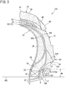
- FIG. 3 shows a part of a pneumatic tire 102 according to another embodiment of the present invention.
- FIG. 3 shows a part of a cross-section of the tire 102 along a plane including the rotation axis of the tire 102.
- the right-left direction is the axial direction of the tire 102
- the up-down direction is the radial direction of the tire 102.
- the direction perpendicular to the surface of the sheet of FIG. 3 is the circumferential direction of the tire 102.
- the tire 102 has the same structure as the structure of the tire 12 shown in FIG. 1 , except for a clinch 104. Therefore, in FIG. 3 , members that are the same as the members of the tire 12 in FIG. 1 are denoted by the same reference characters and the description thereof is omitted.
- the side surface 60 has the flange opposed surface 64 opposed to the flange F of the rim R.
- the flange opposed surface 64 is formed to be a surface having a diameter increasing outward in the axial direction.
- the shape of the flange opposed surface 64 is represented by a circular arc, and the radius of the circular arc is not less than 12.0 mm and not greater than 18.0 mm.
- the clinch 104 includes an inner clinch 106 and an outer clinch 108.
- the inner clinch 106 is located between the flange F and the carcass 22 in a state where the tire 102 is mounted on the rim R.
- the outer clinch 108 is located radially outward of the inner clinch 106.
- the inner clinch 106 and the outer clinch 108 are each formed from a crosslinked rubber.
- a complex elastic modulus E*s of the outer clinch 108 is less than a complex elastic modulus E*u of the inner clinch 106.
- the ratio of the complex elastic modulus E*s of the outer clinch 108 relative to the complex elastic modulus E*u of the inner clinch 106 is preferably not less than 0.5, and preferably not greater than 0.9.
- the complex elastic modulus E*u of the inner clinch 106 and the complex elastic modulus E*s of the outer clinch 108 are measured in the same manner as the complex elastic modulus E*c of the clinch 18 of the tire 12 shown in FIG. 1 .
- the ratio of the complex elastic modulus E*s of the outer clinch 108 relative to the complex elastic modulus E*u of the inner clinch 106 is set to be not less than 0.5, the stiffness is appropriately maintained and necessary run-flat durability is ensured. From this standpoint, the ratio is more preferably not less than 0.50.
- the ratio of the complex elastic modulus E*s of the outer clinch 108 relative to the complex elastic modulus E*u of the inner clinch 106 is set to be not greater than 0.9, the bead 20 portion is readily bent in its entirety, so that concentration of stress on the carcass 22 extending along the inner surface 66 of the bead 20 is inhibited. In the tire 102, occurrence of pinch cut is inhibited. From this standpoint, the ratio is more preferably not greater than 0.90, and even more preferably not greater than 0.85.
- the complex elastic modulus E*u of the inner clinch 106 is not less than 50 MPa and not greater than 60 MPa. In the tire 102, more preferably, the complex elastic modulus E*u of the inner clinch 106 is not less than 50 MPa and not greater than 60 MPa, and the ratio of the complex elastic modulus E*s of the outer clinch 108 relative to the complex elastic modulus E*u of the inner clinch 106 is not less than 0.5 and not greater than 0.9.
- reference character PC represents a radially outer end of the inner clinch 106.
- a double-headed arrow Hb represents the distance in the radial direction from the bead base line BBL to the radially outer end PC of the inner clinch 106.
- reference character PD represents a radially inner end of the outer clinch 108. In the tire 102, the radially inner end PD of the outer clinch 108 is located radially inward of the radially outer end PC of the inner clinch 106.
- the distance Hb in the radial direction from the bead base line BBL to the radially outer end PC of the inner clinch 106 is preferably not less than 12.0 mm, and preferably not greater than 15.0 mm.
- the distance Hb is set to be not less than 12.0 mm, the stiffness is appropriately maintained and necessary run-flat durability is ensured.
- the distance Hb is set to be not greater than 15.0 mm, the bead 20 portion is readily bent in its entirety, so that concentration of stress on the carcass 22 extending along the inner surface 66 of the bead 20 is inhibited. In the tire 102, occurrence of pinch cut is inhibited.
- a boundary 110 between the inner clinch 106 and the outer clinch 108 is tilted relative to the axial direction, and an axially outer end 110a of the boundary 110 is located radially outward of an axially inner end 110b of the boundary 110.
- the boundary 110 may be formed to extend in the axial direction.
- the boundary 110 may be formed such that the boundary 110 is tilted relative to the axial direction and the axially outer end 110a of the boundary 110 is located radially inward of the axially inner end 110b of the boundary 110.
- the axially outer end 110a of the boundary 110 is the radially outer end PC of the inner clinch 106
- the axially inner end 110b of the boundary 110 is the radially inner end PD of the outer clinch 108.
- reference character ⁇ represents the angle of the boundary 110 between the inner clinch 106 and the outer clinch 108 relative to the axial direction.
- the angle ⁇ is the tilt angle of the boundary 110.
- the tilt angle ⁇ is represented as a positive value.
- the tilt angle ⁇ is represented as a negative value.
- the boundary 110 between the inner clinch 106 and the outer clinch 108 preferably extends in the axial direction, or the boundary 110 is preferably tilted relative to the axial direction such that the axially inner end 110b of the boundary 110 is located radially inward of the axially outer end 110a.
- the tilt angle ⁇ of the boundary 110 is preferably not less than 0°, and preferably not greater than 30°.
- FIG. 4 shows a part of a pneumatic tire 122 according to still another embodiment of the present invention.
- FIG. 4 shows a part of a cross-section of the tire 122 along a plane including the rotation axis of the tire 122.
- the right-left direction is the axial direction of the tire 122
- the up-down direction is the radial direction of the tire 122.
- the direction perpendicular to the surface of the sheet of FIG. 4 is the circumferential direction of the tire 122.
- the tire 122 has the same structure as the structure of the tire 12 shown in FIG. 1 , except for a carcass 124. Therefore, in FIG. 4 , members that are the same as the members of the tire 12 in FIG. 1 are denoted by the same reference characters and the description thereof is omitted.
- the side surface 60 has the flange opposed surface 64 opposed to the flange F of the rim R.
- the flange opposed surface 64 is formed to be a surface having a diameter increasing outward in the axial direction.
- the shape of the flange opposed surface 64 is represented by a circular arc, and the radius of the circular arc is not less than 12.0 mm and not greater than 18.0 mm.
- the carcass 124 includes two carcass plies 126. Of the two carcass plies 126 of the carcass 124, the carcass ply 126 located on the inner side is a first carcass ply 128, and the carcass ply 126 located on the outer side is a second carcass ply 130.
- each carcass ply 126 includes multiple carcass cords aligned with each other, which are not shown.
- the carcass cords are covered with a topping rubber.
- Each carcass cord intersects the equator plane CL.
- the angle of each carcass cord relative to the equator plane CL is not less than 70° and not greater than 90°.
- the carcass 124 of the tire 122 has a radial structure.
- a cord formed from an organic fiber is used as the carcass cord.
- the first carcass ply 128 is turned up around each core 42.
- the first carcass ply 128 includes: a first main body portion 128a that extends on and between one core 42 and the other core 42; and a pair of first turned-up portions 128b that are connected to the first main body portion 128a and turned up around the respective cores 42 from the inner side toward the outer side in the axial direction.
- the second carcass ply 130 is turned up around each core 42.
- the second carcass ply 130 includes: a second main body portion 130a that extends on and between one core 42 and the other core 42; and a pair of second turned-up portions 130b that are connected to the second main body portion 130a and turned up around the respective cores 42 from the inner side toward the outer side in the axial direction.
- an end 132 of the second turned-up portion 130b is located radially inward of an end 134 of the first turned-up portion 128b.
- the end 132 of the second turned-up portion 130b is covered with the first turned-up portion 128b from the outer side in the axial direction.
- a double-headed arrow HA represents the cross-sectional height (see JATMA or the like) of the tire 122.
- a double-headed arrow H1 represents the distance in the radial direction from the bead base line BBL to the end 134 of the first turned-up portion 128b.
- a double-headed arrow H2 represents the distance in the radial direction from the bead base line BBL to the end 132 of the second turned-up portion 130b.
- the distance H1 in the radial direction from the bead base line BBL to the end 134 of the first turned-up portion 128b is preferably not less than 40% of the cross-sectional height HA, and preferably not greater than 80% of the cross-sectional height HA.
- the distance H1 is set to be not less than 40% of the cross-sectional height HA, the stiffness is appropriately maintained and necessary run-flat durability is ensured.
- the distance H1 is set to be not greater than 80% of the cross-sectional height HA, the bead 20 portion is readily bent in its entirety, so that concentration of stress on the carcass 124 extending along the inner surface 66 of the bead 20 is inhibited. In the tire 122, occurrence of pinch cut is inhibited.
- the distance H2 in the radial direction from the bead base line BBL to the end 132 of the second turned-up portion 130b is preferably not less than 20% of the cross-sectional height HA, and preferably not greater than 40% of the cross-sectional height HA.
- the distance H2 is set to be not less than 20% of the cross-sectional height HA, the stiffness is appropriately maintained and necessary run-flat durability is ensured.
- the distance H2 is set to be not greater than 40% of the cross-sectional height HA, the bead 20 portion is readily bent in its entirety, so that concentration of stress on the carcass 124 extending along the inner surface 66 of the bead 20 is inhibited. In the tire 122, occurrence of pinch cut is inhibited.
- the end 134 of the first turned-up portion 128b is located between the second main body portion 130a and the belt 24. That is, in the tire 122, the carcass 124 is formed such that the end 134 of the first turned-up portion 128b is disposed between the second main body portion 130a and the belt 24. In the tire 122, the first turned-up portion 128b, together with the side reinforcing layer 28, inhibits deformation of the tire 122 in a punctured state. The first turned-up portion 128b contributes to support of a load in a punctured state.
- the carcass 124 may be formed such that the end 134 of the first turned-up portion 128b is disposed between the second main body portion 130a and the belt 24, so as to support a load in a punctured state.
- the carcass 124 in the case where the above-described ratio of the distance H1 in the radial direction relative to the cross-sectional height HA is not less than 80%, the carcass 124 is in such a state that the end 134 of the first turned-up portion 128b is disposed between the second main body portion 130a and the belt 24.
- the clinch 104 of the tire 102 shown in FIG. 3 may be applied to the clinch 18.
- occurrence of pinch cut is further effectively inhibited.
- a pneumatic tire (tire size 245/40RF19) having the basic structure shown in FIG. 1 and having the specifications indicated in Table 1 below was obtained.
- Example 1 the radius R of the circular arc representing the shape of the flange opposed surface was set to 15.0 mm.
- the distance Lr in the radial direction from the bead base line to the inner end of the flange opposed surface was 15.0 mm.
- the interval T between the flange opposed surface and the flange of the rim was 4.7 mm.
- Example 1 the number of carcass plies of the carcass, i.e., the number of plies was one.
- the width (thickness) TS, in the axial direction, of each sidewall at the maximum width position was 3 mm.
- a tire of Comparative Example 1 was obtained in the same manner as in Example 1 except that the radius R and the distance Lr were changed to set the interval T as indicated in Table 1 below.
- the tire of Comparative Example 1 is a conventional tire.
- a tire of Comparative Example 2 was obtained in the same manner as in Example 1 except that the radius R and the distance Lr were changed to set the interval T as indicated in Table 1 below, and the number of plies was as indicated in Table 1.
- the tire of Comparative Example 2 is a conventional tire.
- the end of the first carcass ply was disposed between the second main body portion of the second carcass ply and the belt.
- the end of the second carcass ply was covered with the first turned-up portion of the first carcass ply, on the side radially inward of the outer end of the apex.
- a tire of Comparative Example 3 was obtained in the same manner as in Example 1 except that the radius R and the distance Lr were changed to set the interval T as indicated in Table 1 below, and the thickness TS was as indicated in Table 1.
- the tire of Comparative Example 3 is a conventional tire.
- Tires of Examples 2 to 10 were obtained in the same manner as in Example 1 except that the radius R and the distance Lr were changed to set the interval T as indicated in Tables 1 and 2 below.
- the tire was mounted to the right front wheel of a test vehicle.
- a test road was prepared, and the test road included a steel projection having a rectangular cross-sectional shape with a height of 110 mm, a width of 100 mm, and a length of 1500 mm.
- a valve core was removed so that the inside of the tire communicated with the atmosphere, and thus a punctured state was produced in the tire.
- the vehicle was caused to progress at an angle of 15° relative to the length direction of the projection, and rode over the projection.
- the tires were mounted to all the wheels of a test vehicle (one person got into the vehicle), and the vehicle was caused to run on a test course having a dry asphalt road surface.
- the driver made evaluation (sensory evaluation) for ride comfort at that time.
- the results are indicated as indexes in the cell for "Ride comfort" in Tables 1 and 2 below. The greater the value is, the more excellent the ride comfort is.
- each sample tire underwent run-flat running under the following conditions, and the running distance until abnormal sound was generated from the tire was measured.
- the results are indicated as indexes in the cell for "RF durability" in Tables 1 and 2 below. The greater the value is, the more excellent the run-flat durability is.
- the examples are highly rated, as compared to the comparative examples.
- occurrence of pinch cut is inhibited, and well-balanced properties are obtained in terms of the weight, the ride comfort, and the run-flat durability. From the evaluation results, advantages of the present invention are clear.
- a pneumatic tire (tire size 245/40RF19) having the basic structure shown in FIG. 1 and having the specifications indicated in Table 3 below was obtained.
- Example 11 the width B1 of the contact surface of each apex with the core was 9.0 mm.
- Example 11 the radius R of the circular arc representing the shape of the flange opposed surface was set to 15.0 mm.
- the distance Lr in the radial direction from the bead base line to the inner end of the flange opposed surface was 15.0 mm.
- the interval T between the flange opposed surface and the flange of the rim was 4.7 mm.
- the number of carcass plies of the carcass, i.e., the number of plies was one.
- the width (thickness) TS, in the axial direction, of each sidewall at the maximum width position was 3 mm.
- a tire of Comparative Example 4 was obtained in the same manner as in Example 11 except that the radius R and the distance Lr were changed to set the interval T as indicated in Table 3 below.
- the tire of Comparative Example 4 is a conventional tire.
- Tires of Examples 12 to 15 were each obtained in the same manner as in Example 11 except that the width B2 was as indicated in Table 3 below.
- Tires of Examples 16 to 21 were each obtained in the same manner as in Example 11 except that the width B1 and the width B2 were as indicated in Table 4 below.
- the examples are highly rated, as compared to the comparative example.
- occurrence of pinch cut is inhibited, and well-balanced properties are obtained in terms of the weight and the run-flat durability. From the evaluation results, advantages of the present invention are clear.
- a pneumatic tire (tire size 245/40RF19) having the basic structure shown in FIG. 3 and having the specifications indicated in Table 5 below was obtained.
- Example 22 the complex elastic modulus E*u of each inner clinch was 60 MPa.
- the complex elastic modulus E*s of each outer clinch was 30 MPa.
- the ratio (E*s/E*u) of the complex elastic modulus E*s of the outer clinch relative to the complex elastic modulus E*u of the inner clinch was 0.50.
- the distance Hb in the radial direction from the bead base line to the radially outer end PC of the inner clinch was 12 mm.
- the tilt angle ⁇ of the boundary between the inner clinch and the outer clinch was 30°.
- the radius R of the circular arc representing the shape of the flange opposed surface was set to 15.0 mm.
- the distance Lr in the radial direction from the bead base line to the inner end of the flange opposed surface was 15.0 mm.
- the interval T between the flange opposed surface and the flange of the rim was 4.7 mm.
- the number of carcass plies of the carcass, i.e., the number of plies was one.
- the width (thickness) TS, in the axial direction, of each sidewall at the maximum width position was 3 mm.
- a tire of Comparative Example 5 was obtained in the same manner as in Example 22 except that the radius R and the distance Lr were changed to set the interval T as indicated in Table 5 below, and each clinch was formed of a single rubber composition.
- the tire of Comparative Example 5 is a conventional tire.
- the complex elastic modulus E*c of the clinch was 60 MPa.
- Example 23 A tire of Example 23 was obtained in the same manner as in Example 22 except that the tilt angle ⁇ was as indicated in Table 5 below.
- Example 24 A tire of Example 24 was obtained in the same manner as in Example 22 except that the distance Hb and the tilt angle ⁇ were as indicated in Table 5 below.
- a tire of Example 25 was obtained in the same manner as in Example 22 except that the radius R and the distance Lr were changed to set the interval T as indicated in Table 5 below.
- Example 26 A tire of Example 26 was obtained in the same manner as in Example 22 except that the complex elastic modulus E*s was changed to set the ratio (E*s/E*u) as indicated in Table 5 below, and the distance Hb and the tilt angle ⁇ were as indicated in Table 5 below.
- Example 27 A tire of Example 27 was obtained in the same manner as in Example 22 except that the distance Hb and the tilt angle ⁇ were as indicated in Table 5 below.
- Tires of Examples 28 to 33 were obtained in the same manner as in Example 22 except that the complex elastic modulus E*s was changed to set the ratio (E*s/E*u) as indicated in Table 6 below, and the tilt angle ⁇ was as indicated in Table 6 below.
- the weight of each sample tire was measured. The results are indicated as indexes in the cell for "Weight" in Tables 5 and 6 below. The less the value is, the less the weight is.
- the examples are highly rated, as compared to the comparative example.
- occurrence of pinch cut is inhibited, and well-balanced properties are obtained in terms of the weight, the ride comfort, and the run-flat durability. From the evaluation results, advantages of the present invention are clear.
Landscapes
- Engineering & Computer Science (AREA)
- Mechanical Engineering (AREA)
- Tires In General (AREA)
Description
- The present application is based upon and claims the benefit of priority to Japanese Patent Application No.
2018-132269, filed July 12, 2018 - The present invention relates to pneumatic tires such as disclosed for instance in
US 2017/225522 A1 ,EP 2 072 289 A1EP 3 315 327 A1 ,US 2016/001608 A1 ,EP 3 505 371 A1 orWO 2019/115055 A1 . More specifically, the present invention relates to side-reinforcing type run flat tires. - A pneumatic tire as a run flat tire has side reinforcing layers formed inward of sidewalls. The side reinforcing layers are formed from a crosslinked rubber. In a state where the internal pressure is reduced due to puncture, i.e., in a punctured state, the side reinforcing layers support a load.
- When a tire passes on a stepped portion such as a pothole in a road surface, a high impact force acts on the tire. The tire is pressed between the road surface and a flange of a rim, and a portion of the tire from the sidewall to a clinch is greatly deformed. A high tensile force acts on cords included in a carcass, and, depending on the degree of the tensile force, the cords may be broken. Such damage accompanied with breakage of the cords is called pinch cut.
-
FIG. 5 shows atire 2 in a deformed state in the case of thetire 2 being pressed between a road surface D and a flange F of a rim R. As shown inFIG. 5 , acarcass 8 is curved at aside reinforcing layer 4 portion and abead 6 portion. At theside reinforcing layer 4 portion, thecarcass 8 has a shape projecting outward, and, at thebead 6 portion, thecarcass 8 has a shape projecting inward. - By analysis using a finite element method (FEM), it has been confirmed that, in the case of a run flat tire, a high tensile force acts on the carcass 8 (more specifically, cords included in the carcass 8) extending along an
inner surface 10 of thebead 6. That is, in the case of a run flat tire, there is a possibility that pinch cut may occur in thecarcass 8 extending along theinner surface 10 of thebead 6. - In order to prevent occurrence of pinch cut in a run flat tire, studies are made for controlling the stiffness of an apex portion to reduce a tensile force acting on the cords (for example, Japanese Laid-Open Patent Publication No.
2015-199473 - In Japanese Laid-Open Patent Publication No.
2015-199473 - In order to prevent occurrence of pinch cut, in addition to a filler being provided as in Japanese Laid-Open Patent Publication No.
2015-199473 - However, in each of the above methods, the stiffness is increased, and thus ride comfort may be degraded. Also, due to increase in the weight, the rolling resistance may be increased. Furthermore, such approaches in which the stiffness is increased have not successfully provided great effects as expected.
- Durability during running in a punctured state, i.e., run-flat running, has been improved, so that it is possible to run over a sufficient distance with the tire in a punctured state. Accordingly, it is required to establish technology that can prevent occurrence of pinch cut while inhibiting deterioration in ride comfort and increase in the weight, on the premise that necessary durability is ensured though durability in run-flat running is sacrificed to a certain extent.
- The present invention has been made in view of the above circumstances, and an object of the present invention is to provide a pneumatic tire that enables inhibition of occurrence of pinch cut.
- As a result of a thorough study on technology for inhibiting occurrence of pinch cut, the present inventors have found that, in a state where a tire is mounted on a rim, when a distance is ensured between the tire and a flange of the rim and the bead portion is readily bent, tensile force acts on the entire carcass and stress concentrating on the apex portion is reduced, leading to completion of the present invention.
- A pneumatic tire according to the present invention includes: a pair of beads each including a core extending in a circumferential direction; a carcass extending on and between one of the beads and the other of the beads; and a pair of side reinforcing layers each located axially inward of the carcass. The tire has an outer surface including a tread surface configured to be in contact with a road surface; seat contact surfaces each of which is configured to be in contact with a seat of a rim on which the tire is to be mounted; and side surfaces extending on and between the tread surface and the seat contact surfaces. Each side surface includes a flange contact surface which is to be in contact with a flange of the rim when the tire is mounted on the rim, and a flange opposed surface which is located radially outward of the flange contact surface and is to be opposed to the flange. The flange opposed surface is formed to be a surface having a diameter increasing outward in an axial direction. A shape of the flange opposed surface is represented by a circular arc in a cross-section of the tire as taken along a plane including a rotation axis of the tire, and a radius of the circular arc is not less than 12.0 mm and not greater than 18.0 mm.
- Preferably, the pneumatic tire further includes rim guards which are located radially outward of the rim in a state where the tire is mounted on the rim, and project outward in the axial direction. Each rim guard has a shape expanding from a top portion thereof so as to be tapered in the cross-section of the tire, and a surface, on a bead side, of the rim guard forms the flange opposed surface.
- Preferably, in the pneumatic tire, a distance in a radial direction from a bead base line to an inner end of the flange opposed surface is not less than 11.0 mm and not greater than 20.0 mm. More preferably, in the pneumatic tire, a distance in the radial direction from the bead base line to the inner end of the flange opposed surface is not less than 12.0 mm and not greater than 18.0 mm.
- Preferably, in an assembly of the pneumatic tire and a rim, in a state where the tire is mounted on the rim, an interval between the flange opposed surface and the flange is not less than 2.6 mm and not greater than 6.0 mm, the interval being measured along a line that is normal to the flange opposed surface and passes through a position, on the flange, corresponding to 90% of a distance in a radial direction from a bead base line to a radially outer end of the flange of the rim.
- Preferably, the pneumatic tire further includes: a tread having the tread surface; a pair of sidewalls extending radially inward from ends of the tread along the carcass, on an axially outer side of the carcass; and a pair of clinches located radially inward of the sidewalls, and each rim guard is formed by a part of a corresponding one of the sidewalls and a part of a corresponding one of the clinches.
- Preferably, in the pneumatic tire, each clinch includes: an inner clinch which is located between the flange and the carcass in a state where the tire is mounted on the rim; and an outer clinch which is located radially outward of the inner clinch. A ratio of a complex elastic modulus of the outer clinch relative to a complex elastic modulus of the inner clinch is not less than 0.5 and not greater than 0.9.
- Preferably, in the pneumatic tire, a distance in a radial direction from a bead base line to a radially outer end of the inner clinch is not less than 12.0 mm and not greater than 15.0 mm.
- Preferably, in the pneumatic tire, in the cross-section of the tire, a boundary between the inner clinch and the outer clinch extends in the axial direction, or is tilted relative to the axial direction such that an inner end of the boundary is located radially inward of an outer end of the boundary. An angle of the boundary relative to the axial direction is not greater than 30°.
- Preferably, in the pneumatic tire, each bead includes an apex located radially outward of the core. In the cross-section of the tire, a width of a contact surface of the apex with the core is not less than 7.0 mm and not greater than 9.0 mm. A width of the apex at a position distant from a bead base line by 17.5 mm in a radially outward direction is not less than 4.5 mm and not greater than 6.0 mm.
- Preferably, in the pneumatic tire, the carcass includes a first carcass ply and a second carcass ply located outward of the first carcass ply. Each of the first carcass ply and the second carcass ply is turned up around each core from an inner side toward an outer side in the axial direction. Ends of the second carcass ply are located radially inward of ends of the first carcass ply. A distance in a radial direction from a bead base line to each end of the first carcass ply is not less than 40% of a cross-sectional height and not greater than 80% of the cross-sectional height.
- According to the present invention, a pneumatic tire that enables inhibition of occurrence of pinch cut is obtained.
-
-
FIG. 1 is a cross-sectional view of a part of a pneumatic tire according to an embodiment of the present invention. -
FIG. 2 is a cross-sectional view of a part of the tire inFIG. 1 . -
FIG. 3 is a cross-sectional view of a part of a pneumatic tire according to another embodiment of the present invention. -
FIG. 4 is a cross-sectional view of a part of a pneumatic tire according to still another embodiment of the present invention. -
FIG. 5 illustrates occurrence of pinch cut. - The following will describe in detail the present invention based on preferred embodiments with appropriate reference to the drawings.
- In the present invention, a state where a tire is mounted on a normal rim, the internal pressure of the tire is adjusted to a normal internal pressure, and no load is applied to the tire, is referred to as normal state. In the present invention, unless otherwise specified, the dimensions and angles of the tire and each member of the tire are measured in the normal state.
- In the present specification, the normal rim means a rim specified in a standard on which the tire is based. The "standard rim" in the JATMA standard, the "Design Rim" in the TRA standard, and the "Measuring Rim" in the ETRTO standard are normal rims.
- In the present specification, the normal internal pressure means an internal pressure specified in the standard on which the tire is based. The "highest air pressure" in the JATMA standard, the "maximum value" recited in "TIRE LOAD LIMITS AT VARIOUS COLD INFLATION PRESSURES" in the TRA standard, and the "INFLATION PRESSURE" in the ETRTO standard are normal internal pressures. In the case where the
tire 12 is designed for a passenger car, unless otherwise specified, the normal internal pressure is 180 kPa. - In the present specification, a normal load means a load specified in the standard on which the tire is based. The "maximum load capacity" in the JATMA standard, the "maximum value" recited in the "TIRE LOAD LIMITS AT VARIOUS COLD INFLATION PRESSURES" in the TRA standard, and the "LOAD CAPACITY" in the ETRTO standard are normal loads.
-
FIG. 1 shows a part of apneumatic tire 12 according to an embodiment of the present invention. Thetire 12 is mounted to a passenger car. -
FIG. 1 shows a part of a cross-section of thetire 12 along a plane including the rotation axis of thetire 12. InFIG. 1 , the right-left direction is the axial direction of thetire 12, and the up-down direction is the radial direction of thetire 12. The direction perpendicular to the surface of the sheet ofFIG. 1 is the circumferential direction of thetire 12. InFIG. 1 , an alternate long and short dash line CL represents the equator plane of thetire 12. - In
FIG. 1 , thetire 12 is mounted on a rim R. The rim R is a normal rim. The interior of thetire 12 is filled with air, and the internal pressure of thetire 12 is adjusted to a normal internal pressure. No load is applied to thetire 12. - In
FIG. 1 , a solid line BBL extending in the axial direction is a bead base line. The bead base line BBL is a line that defines the rim diameter (see JATMA or the like) of the rim R (normal rim). - The
tire 12 includes atread 14, a pair ofsidewalls 16, a pair ofclinches 18, a pair ofbeads 20, acarcass 22, abelt 24, aband 26, a pair ofside reinforcing layers 28, aninner liner 30, and a pair ofchafers 32. - The outer surface of the
tread 14 comes into contact with a road surface. Thetread 14 has atread surface 34 to be in contact with the road surface. In thetire 12, thetread 14 includes abase portion 36 and acap portion 38 located radially outward of thebase portion 36. In thetire 12, thecap portion 38 includes thetread surface 34. In thetire 12, thebase portion 36 is formed from a crosslinked rubber for which adhesion is taken into consideration. Thecap portion 38 is formed from a crosslinked rubber for which abrasion resistance and grip performance are taken into consideration. - In
FIG. 1 , a double-headed arrow TT represents the thickness of thetread 14 on the equator plane CL. In thetire 12, the thickness TT of thetread 14 is not less than 5 mm and not greater than 15 mm. - Each
sidewall 16 is located axially outward of thecarcass 22. Thesidewall 16 extends radially inward from the end of thetread 14 along thecarcass 22. In thetire 12, thesidewall 16 is formed from a crosslinked rubber for which cut resistance is taken into consideration. In thetire 12, awing 40 is disposed between thesidewall 16 and thetread 14. - In
FIG. 1 , an alternate long and two short dashes line LS represents a virtual outer surface of thetire 12 obtained on the assumption that decorations such as dimples or projections are not formed. Reference character PS represents a position which is specified on the basis of the virtual outer surface and at which thetire 12 has the maximum width in the axial direction. A double-headed arrow TS represents the width (thickness), in the axial direction, of thesidewall 16 at the position PS. In thetire 12, the width TS in the axial direction is not less than 2 mm and not greater than 9 mm. - Each
clinch 18 is located radially inward of thesidewall 16. As shown inFIG. 1 , at least a part of theclinch 18 comes into contact with a flange F of the rim R. - The
clinch 18 is formed from a crosslinked rubber. In thetire 12, theclinch 18 is obtained by vulcanizing a single rubber composition. In thetire 12, a complex elastic modulus E*c of theclinch 18 is not less than 30 MPa and not greater than 60 MPa. - In the present invention, the complex elastic modulus E*c of the
clinch 18 is measured according to the standards of JIS-K 6394 using a viscoelasticity spectrometer under the following conditions. - Initial strain: 10%
- Amplitude: ±2%
- Frequency: 10 Hz
- Deformation mode: tension
- Measurement temperature: 70°C
- Each
bead 20 is located axially inward of theclinch 18. Eachbead 20 includes acore 42 and an apex 44 located radially outward of thecore 42. Thecore 42 extends in the circumferential direction. As shown inFIG. 1 , thecore 42 has a rectangular cross-sectional shape. The apex 44 extends radially outward from thecore 42. In the cross-section of thetire 12 shown inFIG. 1 , the apex 44 is tapered outward in the radial direction. - In
FIG. 1 , reference character PM represents the center of the width, in the axial direction, of acontact surface 46 of the apex 44 with thecore 42. A double-headed arrow LA represents the shortest distance between the width center PM and anouter end 48 of the apex 44. In thetire 12, the shortest distance LA, i.e., the length LA of the apex 44, is not less than 25 mm and not greater than 50 mm. - In the
tire 12, the apex 44 is formed from a crosslinked rubber. In thetire 12, the complex elastic modulus E*a of the apex 44 is not less than 50 MPa and not greater than 100 MPa. The apex 44 has high stiffness. The complex elastic modulus E*a of the apex 44 is measured in the same manner as the complex elastic modulus E*c of theclinch 18 described above. - The
carcass 22 is located inward of thetread 14, thesidewalls 16, and theclinches 18. Thecarcass 22 extends on and between onebead 20 and theother bead 20. Thecarcass 22 includes at least onecarcass ply 50. In thetire 12, thecarcass 22 is formed from onecarcass ply 50. - The carcass ply 50 includes multiple carcass cords aligned with each other, which are not shown. The carcass cords are covered with a topping rubber. Each carcass cord intersects the equator plane CL. In the
tire 12, the angle of each carcass cord relative to the equator plane CL is not less than 70° and not greater than 90°. Thecarcass 22 of thetire 12 has a radial structure. In thetire 12, a cord formed from an organic fiber is used as the carcass cord. - In the
tire 12, the carcass ply 50 is turned up around eachcore 42. The carcass ply 50 includes: amain body portion 50a that extends on and between onecore 42 and theother core 42; and a pair of turned-upportions 50b that are connected to themain body portion 50a and turned up around therespective cores 42 from the inner side toward the outer side in the axial direction. As shown inFIG. 1 , in thetire 12, anend 52 of each turned-upportion 50b is located between themain body portion 50a and thebelt 24. - The
belt 24 is layered over thecarcass 22 in a portion radially inward of thetread 14. In thetire 12, thebelt 24 includes two belt plies 54. - Each belt ply 54 includes multiple belt cords aligned with each other, which are not shown. The belt cords are covered with a topping rubber. Each belt cord is tilted relative to the equator plane CL. The angle of each belt cord relative to the equator plane CL is not less than 10° and not greater than 35°. In the
tire 12, the material of the belt cords is steel. - The
band 26 is located between thetread 14 and thebelt 24 in the radial direction. In thetire 12, theband 26 includes afull band 26f and a pair ofedge bands 26e. - The
full band 26f covers the entirety of thebelt 24. Thefull band 26f has a jointless structure. Thefull band 26f includes a helically wound full band cord, which is not shown. A cord formed from an organic fiber is used as the full band cord. - Each
edge band 26e covers an end portion of thebelt 24, from the outer side of thefull band 26f in the radial direction. Theedge band 26e has a jointless structure. Theedge band 26e includes a helically wound edge band cord, which is not shown. A cord formed from an organic fiber is used as the edge band cord. - The
side reinforcing layer 28 is located axially inward of thesidewall 16. Further, theside reinforcing layer 28 is located axially inward of thecarcass 22. As shown inFIG. 1 , theside reinforcing layer 28 has a crescent-like cross-sectional shape. - The
side reinforcing layer 28 is formed from a crosslinked rubber. In a state where the internal pressure is reduced due to puncture, i.e., in a punctured state, theside reinforcing layer 28 supports a load. Therefore, a vehicle to which thetire 12 is mounted can run over a certain distance in a punctured state. Thetire 12 is a side-reinforcing type run flat tire. - In the
tire 12, from the standpoint of supporting a load, the complex elastic modulus E*r of theside reinforcing layer 28 is preferably not less than 9 MPa. From the standpoint of ride comfort, the complex elastic modulus E*r of theside reinforcing layer 28 is preferably not greater than 14 MPa. The complex elastic modulus E*r of theside reinforcing layer 28 is measured in the same manner as the complex elastic modulus E*c of theclinch 18 described above. - In
FIG. 1 , a double-headed arrow TR represents the width (thickness), in the axial direction, of theside reinforcing layer 28 at the position PS where thetire 12 has the maximum width in the axial direction. In thetire 12, the width TR in the axial direction is not less than 3 mm and not greater than 15 mm. - The
inner liner 30 is located inward of thecarcass 22 and theside reinforcing layer 28. Theinner liner 30 forms the inner surface of thetire 12. Theinner liner 30 is formed from a crosslinked rubber that has an excellent air blocking property. Theinner liner 30 maintains the internal pressure of thetire 12. - Each
chafer 32 is located radially inward of thebead 20. As shown inFIG. 1 , at least a part of thechafer 32 comes into contact with a seat S of the rim R. In thetire 12, thechafer 32 includes a fabric and a rubber with which the fabric is impregnated. - In the
tire 12, thetread 14, thesidewalls 16, theclinches 18, and thechafers 32 form anouter surface 56 of thetire 12. Of theouter surface 56, a portion to be in contact with a road surface is thetread surface 34, a portion to be in contact with the seat S of the rim R is aseat contact surface 58, and a portion between thetread surface 34 and theseat contact surface 58 is aside surface 60. Theouter surface 56 includes thetread surface 34, the seat contact surfaces 58, and the side surfaces 60 extending on and between thetread surface 34 and the seat contact surfaces 58. -
FIG. 2 shows a part of the cross-section of thetire 12 shown inFIG. 1 . InFIG. 2 , a portion of thetire 12 from thesidewall 16 to thebead 20 is shown. InFIG. 2 , the right-left direction is the axial direction of thetire 12, and the up-down direction is the radial direction of thetire 12. The direction perpendicular to the surface of the sheet ofFIG. 2 is the circumferential direction of thetire 12. - As described above, the
tire 12 is mounted on the rim R. Thus, as shown inFIG. 2 , theseat contact surface 58 comes into contact with the seat S of the rim R. Further, a part of theside surface 60 comes into contact with the flange F of the rim R. In thetire 12, a portion, of theside surface 60, which comes into contact with the flange F when thetire 12 is mounted on the rim R is aflange contact surface 62. - In the
tire 12, a portion, of theside surface 60, which is located radially outward of theflange contact surface 62 is opposed to the flange F but is not in contact with the flange F, in the normal state. In thetire 12, the portion that is located radially outward of theflange contact surface 62 and that is opposed to the flange F but is not in contact with the flange F in the normal state, is a flange opposedsurface 64. That is, theside surface 60 includes theflange contact surface 62, and the flange opposedsurface 64 located radially outward of theflange contact surface 62 and opposed to the flange F. - As shown in
FIG. 2 , the flange opposedsurface 64 is formed to be a surface having a diameter increasing outward in the axial direction. In particular, the shape of the flange opposedsurface 64 is represented by a circular arc on the cross-section of thetire 12 as taken along a plane including the rotation axis of thetire 12. InFIG. 2 , an arrow denoted by reference character R represents the radius of the circular arc. In thetire 12, the radius R of the circular arc is not less than 12.0 mm and not greater than 18.0 mm. - In
FIG. 2 , reference character PF represents a radially outer end of the flange F. Reference character PB represents a position, on the flange F, which corresponds to 90% of the distance in the radial direction from the bead base line BBL to the outer end PF. A double-headed arrow T represents the interval between the flange opposedsurface 64 and the flange F. The interval T is measured along a line that passes through the position PB on the flange F and is normal to the flange opposedsurface 64. - In a state where the
tire 12 is mounted on the rim R, more specifically, in the normal state, the interval T between thetire 12 and the flange F of the rim R is sufficiently ensured, as shown inFIG. 2 . More specifically, the interval T in the conventional tire is 2.3 mm, whereas the interval T in thetire 12 is not less than 2.6 mm and not greater than 6.0 mm. In thetire 12, since the interval T between thetire 12 and the flange F of the rim R is sufficiently ensured, thebead 20 portion is readily bent in its entirety. At the time of passing on a stepped portion, in a case where a portion of thetire 12 from thesidewall 16 to theclinch 18 is greatly deformed by being pressed between the road surface and the flange F of the rim R, tensile force acts on the entirety of thecarcass 22. In the conventional tire, there is a possibility that pinch cut may occur in the carcass extending along an inner surface of the bead. In contrast, in thetire 12, stress acting on thecarcass 22 is reduced. In thetire 12, occurrence of pinch cut is inhibited. - In the
tire 12, addition of a filler or the like as in the conventional tire is not needed in order to inhibit occurrence of pinch cut. In thetire 12, increase in the weight is inhibited. In addition, since the stiffness of thebead 20 portion is appropriately maintained, reduction in ride comfort is inhibited. - As described above, in the
tire 12, the interval T between thetire 12 and the flange F of the rim R is sufficiently ensured. Therefore, in thetire 12, the volume of thebead 20 portion is smaller as compared to the conventional tire in which the interval T is small. In thetire 12, theside surface 60 including the flange opposedsurface 64 contributes to weight reduction of thetire 12. - In the
tire 12, thebead 20 portion is readily bent in its entirety. Therefore, it cannot be denied that durability during running in a punctured state, i.e., run-flat running, may be reduced. However, theside surface 60 is formed such that the flange opposedsurface 64 has a predetermined radius R, and the stiffness of thebead 20 portion is appropriately maintained. - Therefore, necessary durability is ensured though durability in run-flat running is sacrificed to a certain extent. In thetire 12, occurrence of pinch cut is inhibited while necessary run-flat durability is ensured. - As described above, in the
tire 12, the radius R of the circular arc representing the shape of the flange opposedsurface 64 is not less than 12.0 mm and not greater than 18.0 mm. From the standpoint that the interval T between the flange opposedsurface 64 and the flange F is more sufficiently ensured and occurrence of pinch cut is effectively inhibited, the radius R is preferably not less than 12.0 mm. From the standpoint that the stiffness is appropriately maintained and necessary run-flat durability is ensured, the radius R is preferably not greater than 18.0 mm. - The
tire 12 includes rim guards 68 projecting axially outward. As shown inFIG. 1 , eachrim guard 68 is formed by a part of thesidewall 16 and a part of theclinch 18. In thetire 12, therim guard 68 may be formed by only a part of thesidewall 16. Therim guard 68 may be formed by only a part of theclinch 18. - The
rim guard 68 is located radially outward of the rim R in a state where thetire 12 is mounted on the rim R, more specifically, in the normal state. Although not shown, therim guard 68 continuously extends in the circumferential direction. - The
rim guard 68 prevents damage to the flange F of the rim R on which thetire 12 is mounted. As shown inFIG. 2 , in the cross-section of thetire 12, therim guard 68 has a shape that expands inward from atop portion 70 so as to be tapered. From the standpoint of prevention of damage to the flange F, therim guard 68 is preferably formed such that thetop portion 70 of therim guard 68 is located axially outward of the flange F in the normal state. - In the
tire 12, anouter surface 72 of therim guard 68 has asurface 74, on thebead 20 side, which extends radially inward from aninner end 70a of thetop portion 70, and asurface 76, on thetread 14 side, which extends radially outward from anouter end 70b of thetop portion 70. In thetire 12, theouter surface 72 of therim guard 68 is a part of theside surface 60, and thesurface 74, on thebead 20 side, of theouter surface 72 of therim guard 68 is the flange opposedsurface 64. - In the
tire 12, therim guard 68 portion has a greater volume as compared to the other portions. Therefore, in thetire 12, therim guard 68 portion has high stiffness. However, thetire 12 is formed such that thesurface 74, on thebead 20 side, of theouter surface 72 of therim guard 68 is the flange opposedsurface 64, and, thus, the interval T between thetire 12 and the flange F of the rim R is sufficiently ensured in the normal state. In thetire 12, thebead 20 portion is readily bent in its entirety though therim guard 68 is provided. In thetire 12, at the time of passing on a stepped portion, even when the portion of thetire 12 from thesidewall 16 to theclinch 18 is greatly deformed by being pressed between a road surface and the flange F of the rim R, stress acting on thecarcass 22 extending along theinner surface 66 of thebead 20 is reduced. In thetire 12, occurrence of pinch cut is inhibited. - From this standpoint, in the case where the
tire 12 includes therim guard 68 located radially outward of the rim R and projecting axially outward in a state where thetire 12 is mounted on the rim R, and therim guard 68 has a shape expanding from thetop portion 70 so as to be tapered in the cross-section of thetire 12, thesurface 74, on thebead 20 side, of therim guard 68 is preferably the flange opposedsurface 64 described above. - In the
tire 12, thesurface 76, on thetread 14 side, of therim guard 68 is formed to be a surface having a diameter increasing inward in the axial direction from theouter end 70b of thetop portion 70 of therim guard 68. Thetire 12 is formed such that the shape of thesurface 76 on thetread 14 side is represented by a circular arc on the cross-section of thetire 12 as taken along a plane including the rotation axis thereof. In thetire 12, the size of the circular arc is determined as appropriate in consideration of the outer surface shape of a radially outer portion of thesurface 76 on thetread 14 side. - In
FIG. 2 , reference character PR represents an inner end of the flange opposedsurface 64. In thetire 12, the inner end PR corresponds to the boundary between the flange opposedsurface 64 and theflange contact surface 62. InFIG. 2 , a double-headed arrow Lr represents a distance in the radial direction from the bead base line BBL to the inner end PR of the flange opposedsurface 64. - In the
tire 12, the distance Lr in the radial direction from the bead base line BBL to the inner end PR of the flange opposedsurface 64 is preferably not less than 11.0 mm, and preferably not greater than 20.0 mm. When the distance Lr is set to be not less than 11.0 mm, the interval T is ensured. In thetire 12, thebead 20 portion is readily bent in its entirety, so that concentration of stress on thecarcass 22 extending along theinner surface 66 of thebead 20 is inhibited. In thetire 12, occurrence of pinch cut is inhibited. From this standpoint, the distance Lr is more preferably not less than 12.0 mm. When the distance Lr is set to be not greater than 20.0 mm, the stiffness is appropriately maintained, so that necessary run-flat durability is ensured. From this standpoint, the distance Lr is more preferably not greater than 18.0 mm. - In
FIG. 2 , a double-headed arrow B1 represents the width of thecontact surface 46 of the apex 44 with thecore 42. The width B1 is measured along a virtual line (not shown) passing through the width center PM and extending in the axial direction. InFIG. 2 , reference character PA represents a specific position on an outer side surface of the apex 44, and the distance in the radial direction from the bead base line BBL to the position PA is 17.5 mm. InFIG. 2 , a double-headed arrow B2 represents the width of the apex 44 at the position PA. That is, the width of the apex 44 represented by the double-headed arrow B2 is the width of the apex 44 at a position that is distant from the bead base line BBL by 17.5 mm in the radially outward direction. The width B2 of the apex 44 is measured along a line that passes through the position PA and is normal to theinner surface 66 of the bead 20 (more specifically, apex 44) in the cross-section shown inFIG. 2 . - In the cross-section of the
tire 12 shown inFIG. 2 , the width B1 of thecontact surface 46 of the apex 44 with thecore 42 is preferably not less than 7.0 mm, and preferably not greater than 9.0 mm. When the width B1 of thecontact surface 46 is set to be not less than 7.0 mm, the stiffness is appropriately maintained, so that necessary run-flat durability is ensured. When the width B1 of thecontact surface 46 is set to be not greater than 9.0 mm, thebead 20 portion is readily bent in its entirety, so that concentration of stress on thecarcass 22 extending along theinner surface 66 of thebead 20 is inhibited. In thetire 12, occurrence of pinch cut is inhibited. - In the cross-section of the
tire 12 shown inFIG. 2 , the width B2 of the apex 44 at the position that is distant from the bead base line BBL by 17.5 mm in the radially outward direction is preferably not less than 4.5 mm, and preferably not greater than 6.0 mm. In thetire 12, when the width B2 of the apex 44 is set to be not less than 4.5 mm, the stiffness is appropriately maintained, so that necessary run-flat durability is ensured. When the width B2 of the apex 44 is set to be not greater than 6.0 mm, thebead 20 portion is readily bent in its entirety, so that concentration of stress on thecarcass 22 extending along theinner surface 66 of thebead 20 is inhibited. In thetire 12, occurrence of pinch cut is inhibited. - In
FIG. 1 , a double-headed arrow HA represents the distance in the radial direction from the bead base line BBL to the equator of thetire 12. The distance HA in the radial direction is the cross-sectional height (see JATMA or the like) of thetire 12. A double-headed arrow HF represents the distance in the radial direction from the bead base line BBL to theend 52 of the turned-upportion 50b of thecarcass ply 50. - As described above, the
carcass 22 of thetire 12 is formed from onecarcass ply 50. In thetire 12, in the case where thecarcass 22 is formed from onecarcass ply 50, the ratio of the distance HF in the radial direction relative to the cross-sectional height HA is preferably not less than 40%, and more preferably not less than 50%, from the standpoint that the stiffness is maintained and necessary run-flat durability is ensured. From the standpoint of weight reduction of thetire 12, the ratio is preferably not greater than 85%. - As described above, in the
tire 12 shown inFIG. 1 , theend 52 of the turned-upportion 50b is located between themain body portion 50a and thebelt 24. That is, in thetire 12, thecarcass 22 is formed such that theend 52 of the turned-upportion 50b is disposed between themain body portion 50a and thebelt 24. In thetire 12, the turned-upportion 50b, together with theside reinforcing layer 28, inhibits deformation of thetire 12 in a punctured state. The turned-upportion 50b contributes to support of a load in a punctured state. From this standpoint, in the case where thecarcass 22 is formed from onecarcass ply 50, thecarcass 22 is preferably formed such that theend 52 of the turned-upportion 50b is disposed between thecarcass 22 and thebelt 24. In thetire 12, when the ratio of the distance HF in the radial direction relative to the cross-sectional height HA described above is not less than 80%, thecarcass 22 is in such a state that theend 52 of the turned-upportion 50b is disposed between thecarcass 22 and thebelt 24. -
FIG. 3 shows a part of apneumatic tire 102 according to another embodiment of the present invention.FIG. 3 shows a part of a cross-section of thetire 102 along a plane including the rotation axis of thetire 102. InFIG. 3 , the right-left direction is the axial direction of thetire 102, and the up-down direction is the radial direction of thetire 102. The direction perpendicular to the surface of the sheet ofFIG. 3 is the circumferential direction of thetire 102. - The
tire 102 has the same structure as the structure of thetire 12 shown inFIG. 1 , except for aclinch 104. Therefore, inFIG. 3 , members that are the same as the members of thetire 12 inFIG. 1 are denoted by the same reference characters and the description thereof is omitted. - Also in the
tire 102, similar to thetire 12 shown inFIG. 1 , theside surface 60 has the flange opposedsurface 64 opposed to the flange F of the rim R. The flange opposedsurface 64 is formed to be a surface having a diameter increasing outward in the axial direction. In the cross-section of thetire 102 as taken along a plane including the rotation axis of thetire 102, the shape of the flange opposedsurface 64 is represented by a circular arc, and the radius of the circular arc is not less than 12.0 mm and not greater than 18.0 mm. - In a state where the
tire 102 is mounted on the rim R, the interval between thetire 102 and the flange F of the rim R is sufficiently ensured. In thetire 102, thebead 20 portion is readily bent in its entirety. At the time of passing on a stepped portion, when a portion of thetire 102 from thesidewall 16 to theclinch 104 is greatly deformed by being pressed between the road surface and the flange F of the rim R, tensile force acts on the entirety of thecarcass 22. In the conventional tire, there is a possibility that pinch cut may occur in thecarcass 22 extending along theinner surface 66 of thebead 20. In contrast, in thetire 102, stress acting on thecarcass 22 is reduced. In thetire 102, occurrence of pinch cut is inhibited. - Further, in the
tire 102, theclinch 104 includes aninner clinch 106 and anouter clinch 108. As shown inFIG. 3 , theinner clinch 106 is located between the flange F and thecarcass 22 in a state where thetire 102 is mounted on the rim R. Theouter clinch 108 is located radially outward of theinner clinch 106. - In the
tire 102, theinner clinch 106 and theouter clinch 108 are each formed from a crosslinked rubber. In particular, in thetire 102, a complex elastic modulus E*s of theouter clinch 108 is less than a complex elastic modulus E*u of theinner clinch 106. Specifically, the ratio of the complex elastic modulus E*s of theouter clinch 108 relative to the complex elastic modulus E*u of theinner clinch 106 is preferably not less than 0.5, and preferably not greater than 0.9. The complex elastic modulus E*u of theinner clinch 106 and the complex elastic modulus E*s of theouter clinch 108 are measured in the same manner as the complex elastic modulus E*c of theclinch 18 of thetire 12 shown inFIG. 1 . - In the
tire 102, when the ratio of the complex elastic modulus E*s of theouter clinch 108 relative to the complex elastic modulus E*u of theinner clinch 106 is set to be not less than 0.5, the stiffness is appropriately maintained and necessary run-flat durability is ensured. From this standpoint, the ratio is more preferably not less than 0.50. - In the
tire 102, when the ratio of the complex elastic modulus E*s of theouter clinch 108 relative to the complex elastic modulus E*u of theinner clinch 106 is set to be not greater than 0.9, thebead 20 portion is readily bent in its entirety, so that concentration of stress on thecarcass 22 extending along theinner surface 66 of thebead 20 is inhibited. In thetire 102, occurrence of pinch cut is inhibited. From this standpoint, the ratio is more preferably not greater than 0.90, and even more preferably not greater than 0.85. - In the
tire 102, from the standpoint that necessary run-flat durability is ensured, and occurrence of pinch cut is effectively inhibited, preferably, the complex elastic modulus E*u of theinner clinch 106 is not less than 50 MPa and not greater than 60 MPa. In thetire 102, more preferably, the complex elastic modulus E*u of theinner clinch 106 is not less than 50 MPa and not greater than 60 MPa, and the ratio of the complex elastic modulus E*s of theouter clinch 108 relative to the complex elastic modulus E*u of theinner clinch 106 is not less than 0.5 and not greater than 0.9. - In
FIG. 3 , reference character PC represents a radially outer end of theinner clinch 106. A double-headed arrow Hb represents the distance in the radial direction from the bead base line BBL to the radially outer end PC of theinner clinch 106. InFIG. 3 , reference character PD represents a radially inner end of theouter clinch 108. In thetire 102, the radially inner end PD of theouter clinch 108 is located radially inward of the radially outer end PC of theinner clinch 106. - In the
tire 102, the distance Hb in the radial direction from the bead base line BBL to the radially outer end PC of theinner clinch 106 is preferably not less than 12.0 mm, and preferably not greater than 15.0 mm. When the distance Hb is set to be not less than 12.0 mm, the stiffness is appropriately maintained and necessary run-flat durability is ensured. When the distance Hb is set to be not greater than 15.0 mm, thebead 20 portion is readily bent in its entirety, so that concentration of stress on thecarcass 22 extending along theinner surface 66 of thebead 20 is inhibited. In thetire 102, occurrence of pinch cut is inhibited. - As shown in
FIG. 3 , aboundary 110 between theinner clinch 106 and theouter clinch 108 is tilted relative to the axial direction, and an axiallyouter end 110a of theboundary 110 is located radially outward of an axiallyinner end 110b of theboundary 110. In thetire 102, theboundary 110 may be formed to extend in the axial direction. Theboundary 110 may be formed such that theboundary 110 is tilted relative to the axial direction and the axiallyouter end 110a of theboundary 110 is located radially inward of the axiallyinner end 110b of theboundary 110. In thetire 102 shown inFIG. 3 , the axiallyouter end 110a of theboundary 110 is the radially outer end PC of theinner clinch 106, and the axiallyinner end 110b of theboundary 110 is the radially inner end PD of theouter clinch 108. - In
FIG. 3 , reference character α represents the angle of theboundary 110 between theinner clinch 106 and theouter clinch 108 relative to the axial direction. The angle α is the tilt angle of theboundary 110. In the present invention, as shown inFIG. 3 , in the case where theboundary 110 is tilted relative to the axial direction such that the axiallyinner end 110b of theboundary 110 is located radially inward of the axiallyouter end 110a thereof, the tilt angle α is represented as a positive value. In the case where theboundary 110 is tilted relative to the axial direction such that the axiallyinner end 110b of theboundary 110 is located radially outward of the axiallyouter end 110a thereof, the tilt angle α is represented as a negative value. - In the
tire 102, from the standpoint that necessary run-flat durability is ensured and occurrence of pinch cut is effectively inhibited, in the cross-section of thetire 102 as taken along a plane including the rotation axis of thetire 102, theboundary 110 between theinner clinch 106 and theouter clinch 108 preferably extends in the axial direction, or theboundary 110 is preferably tilted relative to the axial direction such that the axiallyinner end 110b of theboundary 110 is located radially inward of the axiallyouter end 110a. Specifically, the tilt angle α of theboundary 110 is preferably not less than 0°, and preferably not greater than 30°. -
FIG. 4 shows a part of apneumatic tire 122 according to still another embodiment of the present invention.FIG. 4 shows a part of a cross-section of thetire 122 along a plane including the rotation axis of thetire 122. InFIG. 4 , the right-left direction is the axial direction of thetire 122, and the up-down direction is the radial direction of thetire 122. The direction perpendicular to the surface of the sheet ofFIG. 4 is the circumferential direction of thetire 122. - The
tire 122 has the same structure as the structure of thetire 12 shown inFIG. 1 , except for acarcass 124. Therefore, inFIG. 4 , members that are the same as the members of thetire 12 inFIG. 1 are denoted by the same reference characters and the description thereof is omitted. - Also in the
tire 122, similar to thetire 12 shown inFIG. 1 , theside surface 60 has the flange opposedsurface 64 opposed to the flange F of the rim R. The flange opposedsurface 64 is formed to be a surface having a diameter increasing outward in the axial direction. In the cross-section of thetire 122 as taken along a plane including the rotation axis of thetire 122, the shape of the flange opposedsurface 64 is represented by a circular arc, and the radius of the circular arc is not less than 12.0 mm and not greater than 18.0 mm. - In a state where the
tire 122 is mounted on the rim R, the interval between thetire 122 and the flange F of the rim R is sufficiently ensured. In thetire 122, thebead 20 portion is readily bent in its entirety. At the time of passing on a stepped portion, when a portion of thetire 122 from thesidewall 16 to theclinch 18 is greatly deformed by being pressed between the road surface and the flange F of the rim R, tensile force acts on the entirety of thecarcass 124. In the conventional tire, there is a possibility that pinch cut may occur in the carcass extending along the inner surface of the bead. In contrast, in thetire 122, stress acting on thecarcass 124 is reduced. In thetire 122, occurrence of pinch cut is inhibited. - Further, in the
tire 122, thecarcass 124 includes two carcass plies 126. Of the two carcass plies 126 of thecarcass 124, the carcass ply 126 located on the inner side is afirst carcass ply 128, and the carcass ply 126 located on the outer side is asecond carcass ply 130. - Similar to the carcass ply 50 of the
tire 12 shown inFIG. 1 , each carcass ply 126 includes multiple carcass cords aligned with each other, which are not shown. The carcass cords are covered with a topping rubber. Each carcass cord intersects the equator plane CL. In thetire 122, the angle of each carcass cord relative to the equator plane CL is not less than 70° and not greater than 90°. Thecarcass 124 of thetire 122 has a radial structure. In thetire 122, a cord formed from an organic fiber is used as the carcass cord. - In the
tire 122, thefirst carcass ply 128 is turned up around eachcore 42. Thefirst carcass ply 128 includes: a firstmain body portion 128a that extends on and between onecore 42 and theother core 42; and a pair of first turned-upportions 128b that are connected to the firstmain body portion 128a and turned up around therespective cores 42 from the inner side toward the outer side in the axial direction. - In the
tire 122, thesecond carcass ply 130 is turned up around eachcore 42. Thesecond carcass ply 130 includes: a secondmain body portion 130a that extends on and between onecore 42 and theother core 42; and a pair of second turned-upportions 130b that are connected to the secondmain body portion 130a and turned up around therespective cores 42 from the inner side toward the outer side in the axial direction. As shown inFIG. 4 , in thetire 122, anend 132 of the second turned-upportion 130b is located radially inward of anend 134 of the first turned-upportion 128b. Theend 132 of the second turned-upportion 130b is covered with the first turned-upportion 128b from the outer side in the axial direction. - In
FIG. 4 , a double-headed arrow HA represents the cross-sectional height (see JATMA or the like) of thetire 122. A double-headed arrow H1 represents the distance in the radial direction from the bead base line BBL to theend 134 of the first turned-upportion 128b. A double-headed arrow H2 represents the distance in the radial direction from the bead base line BBL to theend 132 of the second turned-upportion 130b. - In the
tire 122, the distance H1 in the radial direction from the bead base line BBL to theend 134 of the first turned-upportion 128b is preferably not less than 40% of the cross-sectional height HA, and preferably not greater than 80% of the cross-sectional height HA. When the distance H1 is set to be not less than 40% of the cross-sectional height HA, the stiffness is appropriately maintained and necessary run-flat durability is ensured. When the distance H1 is set to be not greater than 80% of the cross-sectional height HA, thebead 20 portion is readily bent in its entirety, so that concentration of stress on thecarcass 124 extending along theinner surface 66 of thebead 20 is inhibited. In thetire 122, occurrence of pinch cut is inhibited. - In the
tire 122, the distance H2 in the radial direction from the bead base line BBL to theend 132 of the second turned-upportion 130b is preferably not less than 20% of the cross-sectional height HA, and preferably not greater than 40% of the cross-sectional height HA. When the distance H2 is set to be not less than 20% of the cross-sectional height HA, the stiffness is appropriately maintained and necessary run-flat durability is ensured. When the distance H2 is set to be not greater than 40% of the cross-sectional height HA, thebead 20 portion is readily bent in its entirety, so that concentration of stress on thecarcass 124 extending along theinner surface 66 of thebead 20 is inhibited. In thetire 122, occurrence of pinch cut is inhibited. - As shown in
FIG. 4 , in thetire 122, theend 134 of the first turned-upportion 128b is located between the secondmain body portion 130a and thebelt 24. That is, in thetire 122, thecarcass 124 is formed such that theend 134 of the first turned-upportion 128b is disposed between the secondmain body portion 130a and thebelt 24. In thetire 122, the first turned-upportion 128b, together with theside reinforcing layer 28, inhibits deformation of thetire 122 in a punctured state. The first turned-upportion 128b contributes to support of a load in a punctured state. From this standpoint, in the case where thecarcass 124 includes two carcass plies 126, thecarcass 124 may be formed such that theend 134 of the first turned-upportion 128b is disposed between the secondmain body portion 130a and thebelt 24, so as to support a load in a punctured state. In thetire 122, in the case where the above-described ratio of the distance H1 in the radial direction relative to the cross-sectional height HA is not less than 80%, thecarcass 124 is in such a state that theend 134 of the first turned-upportion 128b is disposed between the secondmain body portion 130a and thebelt 24. - In the
tire 122, theclinch 104 of thetire 102 shown inFIG. 3 may be applied to theclinch 18. In thetire 122, while necessary run-flat durability is ensured, occurrence of pinch cut is further effectively inhibited. - As is obvious from the above description, according to the present invention, a pneumatic tire that enables inhibition of occurrence of pinch cut is obtained.
- The embodiments disclosed above are merely illustrative in all aspects and are not restrictive. The technical scope of the present invention is not limited to the above-described embodiments, and all changes which come within the range of equivalency of the configurations recited in the claims are therefore intended to be included therein.
- The following will describe the present invention in further detail by means of examples, etc., but the present invention is not limited to these examples.
- A pneumatic tire (tire size = 245/40RF19) having the basic structure shown in
FIG. 1 and having the specifications indicated in Table 1 below was obtained. - In Example 1, the radius R of the circular arc representing the shape of the flange opposed surface was set to 15.0 mm. The distance Lr in the radial direction from the bead base line to the inner end of the flange opposed surface was 15.0 mm. The interval T between the flange opposed surface and the flange of the rim was 4.7 mm.
- In Example 1, the number of carcass plies of the carcass, i.e., the number of plies was one. The width (thickness) TS, in the axial direction, of each sidewall at the maximum width position was 3 mm.
- A tire of Comparative Example 1 was obtained in the same manner as in Example 1 except that the radius R and the distance Lr were changed to set the interval T as indicated in Table 1 below. The tire of Comparative Example 1 is a conventional tire.
- A tire of Comparative Example 2 was obtained in the same manner as in Example 1 except that the radius R and the distance Lr were changed to set the interval T as indicated in Table 1 below, and the number of plies was as indicated in Table 1. The tire of Comparative Example 2 is a conventional tire. In the carcass of Comparative Example 2, the end of the first carcass ply was disposed between the second main body portion of the second carcass ply and the belt. The end of the second carcass ply was covered with the first turned-up portion of the first carcass ply, on the side radially inward of the outer end of the apex.
- A tire of Comparative Example 3 was obtained in the same manner as in Example 1 except that the radius R and the distance Lr were changed to set the interval T as indicated in Table 1 below, and the thickness TS was as indicated in Table 1. The tire of Comparative Example 3 is a conventional tire.
- Tires of Examples 2 to 10 were obtained in the same manner as in Example 1 except that the radius R and the distance Lr were changed to set the interval T as indicated in Tables 1 and 2 below.
- The weight of each sample tire was measured. The results are indicated as indexes in the cell for "Weight" in Tables 1 and 2 below. The less the value is, the less the weight is.
- Each sample tire was fitted onto a rim (size = 8.5J), and was inflated with air to adjust the internal pressure of the tire to 230 kPa. The tire was mounted to the right front wheel of a test vehicle. On the lateral side, a test road was prepared, and the test road included a steel projection having a rectangular cross-sectional shape with a height of 110 mm, a width of 100 mm, and a length of 1500 mm. A valve core was removed so that the inside of the tire communicated with the atmosphere, and thus a punctured state was produced in the tire. The vehicle was caused to progress at an angle of 15° relative to the length direction of the projection, and rode over the projection. The speed at which the vehicle progressed was sequentially increased from 15 km/h at increments of 3 km/h, and the speed when pinch cut occurred was obtained. The results are indicated as indexes in the cell for "Pinch cut" in Tables 1 and 2 below. The greater the value is, the more excellent the pinch cut resistance is and the more effectively occurrence of pinch cut is inhibited.
- Each sample tire was fitted onto a rim (size = 8.5J), and was inflated with air to adjust the internal pressure of the tire to 230 kPa. The tires were mounted to all the wheels of a test vehicle (one person got into the vehicle), and the vehicle was caused to run on a test course having a dry asphalt road surface. The driver made evaluation (sensory evaluation) for ride comfort at that time. The results are indicated as indexes in the cell for "Ride comfort" in Tables 1 and 2 below. The greater the value is, the more excellent the ride comfort is.
- Using a drum testing machine, each sample tire underwent run-flat running under the following conditions, and the running distance until abnormal sound was generated from the tire was measured. The results are indicated as indexes in the cell for "RF durability" in Tables 1 and 2 below. The greater the value is, the more excellent the run-flat durability is.
- Rim: 8.5 J, Internal pressure: 0 kPa (valve core was removed)
- Load: 4.3 kN
- Speed: 80 km/h
- A difference from Comparative Example 1 serving as a reference was calculated for each evaluation item, and the sum of the calculated differences was obtained. The results are indicated in the cell for "Comprehensive performance" in Tables 1 and 2 below. The greater the value is, the higher the evaluation is. Regarding the weight, the less the value is, the higher the evaluation is. Therefore, the index therefor in each example was subtracted from the index in Comparative Example 1, to calculate the difference from Comparative Example 1. Regarding the pinch cut, the ride comfort, and the run-flat durability, the greater the value is, the higher the evaluation is. Therefore, the index therefor in Comparative Example 1 was subtracted from the index in each example, to calculate the difference from Comparative Example 1.
[Table 1] Comparative Example 1 Comparative Example 2 Comparative Example 3 Example 2 Example 3 Example 1 Example 4 R [mm] 10.0 10.0 10.0 11.0 12.0 15.0 18.0 Lr [mm] 10.0 10.0 10.0 15.0 15.0 15.0 15.0 T [mm] 2.3 2.3 2.3 2.6 3.2 4.7 4.9 Number of plies 1 2 1 1 1 1 1 TS [mm] 3 3 5 3 3 3 3 Weight 100 150 130 99 99 99 98 Pinch cut 100 115 120 118 130 140 145 Ride comfort 100 70 80 99 99 98 98 RF durability 100 120 102 99 99 98 90 Comprehensive performance - -45 -28 17 29 37 35 [Table 2] Example 5 Example 6 Example 7 Example 8 Example 9 Example 10 R [mm] 20.0 20.0 15.0 15.0 15.0 15.0 Lr [mm] 15.0 20.0 20.0 18.0 12.0 11.0 T [mm] 5.3 6 5.5 5.1 3.5 2.8 Number of plies 1 1 1 1 1 1 TS [mm] 3 3 3 3 3 3 Weight 97 97 97 98 99 99 Pinch cut 145 150 145 145 130 120 Ride comfort 96 95 96 98 99 99 RF durability 80 70 80 90 99 99 Comprehensive performance 24 18 24 35 29 19 - As indicated in Table 1 and Table 2, the examples are highly rated, as compared to the comparative examples. In particular, in the examples, occurrence of pinch cut is inhibited, and well-balanced properties are obtained in terms of the weight, the ride comfort, and the run-flat durability. From the evaluation results, advantages of the present invention are clear.
- A pneumatic tire (tire size = 245/40RF19) having the basic structure shown in
FIG. 1 and having the specifications indicated in Table 3 below was obtained. - In Example 11, the width B1 of the contact surface of each apex with the core was 9.0 mm. The width B2 of the apex at a position distant from the bead base line by 17.5 mm in the radially outward direction was 5.5 mm.
- In Example 11, the radius R of the circular arc representing the shape of the flange opposed surface was set to 15.0 mm. The distance Lr in the radial direction from the bead base line to the inner end of the flange opposed surface was 15.0 mm. The interval T between the flange opposed surface and the flange of the rim was 4.7 mm. The number of carcass plies of the carcass, i.e., the number of plies was one. The width (thickness) TS, in the axial direction, of each sidewall at the maximum width position was 3 mm.
- A tire of Comparative Example 4 was obtained in the same manner as in Example 11 except that the radius R and the distance Lr were changed to set the interval T as indicated in Table 3 below. The tire of Comparative Example 4 is a conventional tire.
- Tires of Examples 12 to 15 were each obtained in the same manner as in Example 11 except that the width B2 was as indicated in Table 3 below.
- Tires of Examples 16 to 21 were each obtained in the same manner as in Example 11 except that the width B1 and the width B2 were as indicated in Table 4 below.
- The weight of each sample tire was measured. The results are indicated as indexes in the cell for "Weight" in Tables 3 and 4 below. The less the value is, the less the weight is.
- Indexes regarding pinch cut properties were obtained in the same manner as in Experiment 1 described above. The results are indicated in the cell for "Pinch cut" in Tables 3 and 4 below. The greater the value is, the more excellent the pinch cut resistance is and the more effectively occurrence of pinch cut is inhibited.
- Indexes regarding run-flat durability were obtained in the same manner as in Experiment 1 described above. The results are indicated in the cell for "RF durability" in Tables 3 and 4 below. The greater the value is, the more excellent the run-flat durability is.
- A difference from Comparative Example 4 serving as a reference was calculated for each evaluation item, and the sum of the calculated differences was obtained. The results are indicated in the cell for "Comprehensive performance" in Tables 3 and 4 below. The greater the value is, the higher the evaluation is. Regarding the weight, the less the value is, the higher the evaluation is. Therefore, the index therefor in each example was subtracted from the index in Comparative Example 4, to calculate the difference from Comparative Example 4. Regarding the pinch cut and the run-flat durability, the greater the value is, the higher the evaluation is. Therefore, the index therefor in Comparative Example 4 was subtracted from the index in each example, to calculate the difference from Comparative Example 4.
[Table 3] Comparative Example 4 Example 12 Example 13 Example 11 Example 14 Example 15 R [mm] 10.0 15.0 15.0 15.0 15.0 15.0 Lr [mm] 10.0 15.0 15.0 15.0 15.0 15.0 T [mm] 2.3 4.7 4.7 4.7 4.7 4.7 Number of plies 1 1 1 1 1 1 TS [mm] 3 3 3 3 3 3 B1 [mm] 9.0 9.0 9.0 9.0 9.0 9.0 B2 [mm] 5.5 3.5 4.5 5.5 6.0 6.5 Weight 100 89 89 99 105 110 Pinch cut 100 145 140 130 115 105 RF durability 100 60 85 98 110 115 Comprehensive performance - 16 36 29 20 10 [Table 4] Example 16 Example 17 Example 18 Example 19 Example 20 Example 21 R [mm] 15.0 15.0 15.0 15.0 15.0 15.0 Lr [mm] 15.0 15.0 15.0 15.0 15.0 15.0 T [mm] 4.7 4.7 4.7 4.7 4.7 4.7 Number of plies 1 1 1 1 1 1 TS [mm] 3 3 3 3 3 3 B1 [mm] 6.0 7.0 7.0 7.0 7.0 7.0 B2 [mm] 4.5 3.5 4.5 5.5 6.0 6.5 Weight 79 79 84 89 99 104 Pinch cut 150 150 145 140 130 115 RF durability 45 45 80 85 90 95 Comprehensive performance 16 16 41 36 21 6 - As indicated in Table 3 and Table 4, the examples are highly rated, as compared to the comparative example. In particular, in the examples, occurrence of pinch cut is inhibited, and well-balanced properties are obtained in terms of the weight and the run-flat durability. From the evaluation results, advantages of the present invention are clear.
- A pneumatic tire (tire size = 245/40RF19) having the basic structure shown in
FIG. 3 and having the specifications indicated in Table 5 below was obtained. - In Example 22, the complex elastic modulus E*u of each inner clinch was 60 MPa. The complex elastic modulus E*s of each outer clinch was 30 MPa. The ratio (E*s/E*u) of the complex elastic modulus E*s of the outer clinch relative to the complex elastic modulus E*u of the inner clinch was 0.50. The distance Hb in the radial direction from the bead base line to the radially outer end PC of the inner clinch was 12 mm. The tilt angle α of the boundary between the inner clinch and the outer clinch was 30°.
- In Example 22, the radius R of the circular arc representing the shape of the flange opposed surface was set to 15.0 mm. The distance Lr in the radial direction from the bead base line to the inner end of the flange opposed surface was 15.0 mm. The interval T between the flange opposed surface and the flange of the rim was 4.7 mm. The number of carcass plies of the carcass, i.e., the number of plies was one. The width (thickness) TS, in the axial direction, of each sidewall at the maximum width position was 3 mm.
- A tire of Comparative Example 5 was obtained in the same manner as in Example 22 except that the radius R and the distance Lr were changed to set the interval T as indicated in Table 5 below, and each clinch was formed of a single rubber composition. The tire of Comparative Example 5 is a conventional tire. In Comparative Example 5, the complex elastic modulus E*c of the clinch was 60 MPa.
- A tire of Example 23 was obtained in the same manner as in Example 22 except that the tilt angle α was as indicated in Table 5 below.
- A tire of Example 24 was obtained in the same manner as in Example 22 except that the distance Hb and the tilt angle α were as indicated in Table 5 below.
- A tire of Example 25 was obtained in the same manner as in Example 22 except that the radius R and the distance Lr were changed to set the interval T as indicated in Table 5 below.
- A tire of Example 26 was obtained in the same manner as in Example 22 except that the complex elastic modulus E*s was changed to set the ratio (E*s/E*u) as indicated in Table 5 below, and the distance Hb and the tilt angle α were as indicated in Table 5 below.
- A tire of Example 27 was obtained in the same manner as in Example 22 except that the distance Hb and the tilt angle α were as indicated in Table 5 below.
- Tires of Examples 28 to 33 were obtained in the same manner as in Example 22 except that the complex elastic modulus E*s was changed to set the ratio (E*s/E*u) as indicated in Table 6 below, and the tilt angle α was as indicated in Table 6 below.
- The weight of each sample tire was measured. The results are indicated as indexes in the cell for "Weight" in Tables 5 and 6 below. The less the value is, the less the weight is.
- Indexes regarding pinch cut properties were obtained in the same manner as in Experiment 1 described above. The results are indicated in the cell for "Pinch cut" in Tables 5 and 6 below. The greater the value is, the more excellent the pinch cut resistance is and the more effectively occurrence of pinch cut is inhibited.
- Indexes regarding ride comfort were obtained in the same manner as in Experiment 1 described above. The results are indicated as indexes in the cell for "Ride comfort" in Tables 5 and 6 below. The greater the value is, the more excellent the ride comfort is.
- Indexes regarding run-flat durability were obtained in the same manner as in Experiment 1 described above. The results are indicated in the cell for "RF durability" in Tables 5 and 6 below. The greater the value is, the more excellent the run-flat durability is.
- A difference from Comparative Example 5 serving as a reference was calculated for each evaluation item, and the sum of the calculated differences was obtained. The results are indicated in the cell for "Comprehensive performance" in Tables 5 and 6 below. The greater the value is, the higher the evaluation is. Regarding the weight, the less the value is, the higher the evaluation is. Therefore, the index therefor in each example was subtracted from the index in Comparative Example 5, to calculate the difference from Comparative Example 5. Regarding the pinch cut, ride comfort, and the run-flat durability, the greater the value is, the higher the evaluation is. Therefore, the index therefor in Comparative Example 5 was subtracted from the index in each example, to calculate the difference from Comparative Example 5.
[Table 5] Comparative Example 5 Example 23 Example 24 Example 22 Example 25 Example 26 Example 27 R [mm] 10.0 15.0 15.0 15.0 11.0 15.0 15.0 Lr [mm] 10.0 15.0 15.0 15.0 11.0 15.0 15.0 T [mm] 2.3 4.7 4.7 4.7 2.3 4.7 4.7 Hb [mm] - 12 15 12 12 5 20 E*u [MPa] 60 60 60 60 60 60 60 E*s [MPa] 60 30 30 30 30 50 30 E*s/E*u [-] 1 0.50 0.50 0.50 0.50 0.83 0.50 Angle α [°] - 0 0 30 30 0 0 Number of plies 1 1 1 1 1 1 1 TS [mm] 3 3 3 3 3 3 3 Weight 100 99 99 99 100 99 99 Pinch cut 100 150 145 155 120 150 125 Ride comfort 100 97 98 99 99 88 99 RF durability 100 95 97 93 98 85 99 Comprehensive performance - 43 41 48 17 24 24 [Table 6] Example 28 Example 29 Example 30 Example 31 Example 32 Example 33 R [mm] 15.0 15.0 15.0 15.0 15.0 15.0 Lr [mm] 15.0 15.0 15.0 15.0 15.0 15.0 T [mm] 4.7 4.7 4.7 4.7 4.7 4.7 Hb [mm] 15 12 12 12 12 15 E*u [MPa] 60 60 60 60 60 60 E*s [MPa] 20 50 55 50 50 50 E*s/E*u [-] 0.33 0.83 0.92 0.83 0.83 0.83 Angle α [°] 0 0 0 40 30 -10 Number of plies 1 1 1 1 1 1 TS [mm] 3 3 3 3 3 3 Weight 99 99 99 99 99 99 Pinch cut 145 140 125 150 145 120 Ride comfort 90 99 99 99 99 95 RF durability 90 98 99 80 98 98 Comprehensive performance 26 38 24 30 43 14 - As indicated in Table 5 and Table 6, the examples are highly rated, as compared to the comparative example. In particular, in the examples, occurrence of pinch cut is inhibited, and well-balanced properties are obtained in terms of the weight, the ride comfort, and the run-flat durability. From the evaluation results, advantages of the present invention are clear.
- The above-described technology for inhibiting occurrence of pinch cut can also be applied to various tires.
Claims (11)
- A pneumatic tire (12, 102, 122) comprising:a pair of beads (20) each including a core (42) extending in a circumferential direction;a carcass (22, 124) extending on and between one of the beads (20) and the other of the beads (20); anda pair of side reinforcing layers (28) each located axially inward of the carcass (22, 124),
whereinthe tire (12, 102, 122) has an outer surface comprising a tread surface (34) configured to be in contact with a road surface; seat contact surfaces (58) each of which is configured to be in contact with a seat (S) of a rim (R) on which the tire (12, 102, 122) is to be mounted; and side surfaces (60) extending on and between the tread surface (34) and the seat contact surfaces (58),each side surface (60) includes a flange contact surface (62) which is to be in contact with a flange (F) of the rim (R) when the tire (12, 102, 122) is mounted on the rim (R), and a flange opposed surface (64) which is located radially outward of the flange contact surface (62) and is to be opposed to the flange (F),the flange opposed surface (64) is formed to be a surface having a diameter increasing outward in an axial direction, anda shape of the flange opposed surface (64) is represented by a circular arc in a cross-section of the tire (12, 102, 122) as taken along a plane including a rotation axis of the tire (12, 102, 122),
characterized in thata radius of the circular arc is not less than 12.0 mm and not greater than 18.0 mm. - The pneumatic tire (12, 102, 122) according to claim 1, further comprising rim guards (68) which are located radially outward of the rim (R) in a state where the tire (12, 102, 122) is mounted on the rim (R), and project outward in the axial direction, wherein
each rim guard (68) has a shape expanding from a top portion (70) thereof so as to be tapered in the cross-section of the tire (12, 102, 122), and
a surface, on a bead side, of the rim guard (68) forms the flange opposed surface (64). - The pneumatic tire (12, 102, 122) according to claim 1 or 2, wherein
a distance (Lr) in a radial direction from a bead base line (BBL) to an inner end (PR) of the flange opposed surface (64) is not less than 11.0 mm and not greater than 20.0 mm. - The pneumatic tire (12, 102, 122) according to claim 3, wherein
a distance (Lr) in the radial direction from the bead base line (BBL) to the inner end (PR) of the flange opposed surface (64) is not less than 12.0 mm and not greater than 18.0 mm. - The pneumatic tire (12, 102, 122) according to any one of claims 1 to 4, further comprising:a tread (14) having the tread surface (34);a pair of sidewalls (16) extending radially inward from ends of the tread (14) along the carcass (22, 124), on an axially outer side of the carcass (22, 124); anda pair of clinches (18, 104, 106, 108) located radially inward of the sidewalls (16), whereineach clinch (18, 104, 106, 108) includes: an inner clinch (106) which is located between the flange (F) and the carcass (22, 124) in a state where the tire (12, 102, 122) is mounted on the rim (R); and an outer clinch (108) which is located radially outward of the inner clinch (106), anda ratio of a complex elastic modulus (E*s) of the outer clinch (108) relative to a complex elastic modulus (E*u) of the inner clinch (106) is not less than 0.5 and not greater than 0.9.
- The pneumatic tire (12, 102, 122) according to claim 5, wherein
a distance (Hb) in a radial direction from a bead base line (BBL) to a radially outer end (PC) of the inner clinch (106) is not less than 12.0 mm and not greater than 15.0 mm. - The pneumatic tire (12, 102, 122) according to claim 5 or 6, wherein
each rim guard (68) is formed by a part of a corresponding one of the sidewalls (16) and a part of a corresponding one of the clinches (18, 104, 106, 108). - The pneumatic tire (12, 102, 122) according to any one of claims 5 to 7, wherein
in the cross-section of the tire (12, 102, 122), a boundary (110) between the inner clinch (106) and the outer clinch (108) extends in the axial direction, or is tilted relative to the axial direction such that an inner end of the boundary (110) is located radially inward of an outer end of the boundary (110), and
an angle (α) of the boundary (110) relative to the axial direction is not greater than 30°. - The pneumatic tire (12, 102, 122) according to any one of claims 1 to 8, wherein
each bead (20) includes an apex (44) located radially outward of the core (42),
in the cross-section of the tire (12, 102, 122), a width (B1) of a contact surface (46) of the apex (44) with the core (42) is not less than 7.0 mm and not greater than 9.0 mm, and
a width (B2) of the apex (44) at a position (PA) distant from a bead base line (BBL) by 17.5 mm in a radially outward direction is not less than 4.5 mm and not greater than 6.0 mm. - The pneumatic tire (12, 102, 122) according to claims 1 to 9, wherein
the carcass (22, 124) includes a first carcass ply (126, 128) and a second carcass ply (126, 130) located outward of the first carcass ply (126, 128),
each of the first carcass ply (126, 128) and the second carcass ply (126, 130) is turned up around each core (42) from an inner side toward an outer side in the axial direction,
ends (132) of the second carcass ply (126, 130) are located radially inward of ends (134) of the first carcass ply (126, 128), and
a distance (H1) in a radial direction from a bead base line (BBL) to each end (134) of the first carcass ply (126, 128) is not less than 40% of a cross-sectional height (HA) and not greater than 80% of the cross-sectional height (HA). - Assembly of the pneumatic tire (12, 102, 122) according to any one of claims 1 to 10 and a rim (R) with a flange (F), wherein
in a state where the tire (12, 102, 122) is mounted on the rim (R), an interval (T) between the flange opposed surface (64) and the flange (F) is not less than 2.6 mm and not greater than 6.0 mm, the interval (T) being measured along a line that is normal to the flange opposed surface (64) and passes through a position (PB), on the flange (F), corresponding to 90% of a distance in a radial direction from a bead base line (BBL) to a radially outer end of the flange (F) of the rim (R).
Applications Claiming Priority (1)
| Application Number | Priority Date | Filing Date | Title |
|---|---|---|---|
| JP2018132269 | 2018-07-12 |
Publications (2)
| Publication Number | Publication Date |
|---|---|
| EP3594025A1 EP3594025A1 (en) | 2020-01-15 |
| EP3594025B1 true EP3594025B1 (en) | 2021-02-24 |
Family
ID=67226049
Family Applications (1)
| Application Number | Title | Priority Date | Filing Date |
|---|---|---|---|
| EP19185307.6A Active EP3594025B1 (en) | 2018-07-12 | 2019-07-09 | Pneumatic tire |
Country Status (4)
| Country | Link |
|---|---|
| US (1) | US11964517B2 (en) |
| EP (1) | EP3594025B1 (en) |
| JP (1) | JP7400229B2 (en) |
| CN (1) | CN110712478B (en) |
Cited By (1)
| Publication number | Priority date | Publication date | Assignee | Title |
|---|---|---|---|---|
| US20240262137A1 (en) * | 2021-07-20 | 2024-08-08 | The Yokohama Rubber Co., Ltd | Tire |
Families Citing this family (4)
| Publication number | Priority date | Publication date | Assignee | Title |
|---|---|---|---|---|
| JP2022100772A (en) * | 2020-12-24 | 2022-07-06 | 住友ゴム工業株式会社 | tire |
| JP7701605B2 (en) * | 2021-07-20 | 2025-07-02 | 横浜ゴム株式会社 | tire |
| JP7667437B2 (en) * | 2021-07-20 | 2025-04-23 | 横浜ゴム株式会社 | tire |
| JP2025160602A (en) * | 2024-04-10 | 2025-10-23 | 住友ゴム工業株式会社 | tire |
Family Cites Families (31)
| Publication number | Priority date | Publication date | Assignee | Title |
|---|---|---|---|---|
| JPH0253614A (en) * | 1988-08-18 | 1990-02-22 | Bridgestone Corp | Large vehicle tire |
| JP3971831B2 (en) * | 1997-11-26 | 2007-09-05 | 株式会社ブリヂストン | Pneumatic tire |
| JP3983357B2 (en) | 1997-11-28 | 2007-09-26 | 株式会社ブリヂストン | Pneumatic tire |
| JP3839581B2 (en) * | 1998-03-24 | 2006-11-01 | 住友ゴム工業株式会社 | Pneumatic tire |
| JPH11310015A (en) * | 1998-04-28 | 1999-11-09 | Bridgestone Corp | Pneumatic tire |
| JP2000198333A (en) * | 1998-12-28 | 2000-07-18 | Sumitomo Rubber Ind Ltd | Pneumatic tire |
| US6929046B1 (en) * | 1999-12-16 | 2005-08-16 | The Goodyear Tire & Rubber Company | Tire in with cavities in bead region |
| JP2005238916A (en) * | 2004-02-25 | 2005-09-08 | Yokohama Rubber Co Ltd:The | Tire/wheel assembly |
| JP4445289B2 (en) * | 2004-03-01 | 2010-04-07 | 住友ゴム工業株式会社 | Run flat tire |
| JP2006137252A (en) * | 2004-11-10 | 2006-06-01 | Bridgestone Corp | High performance low-profile tire for passenger four-wheeled car and installation method of tire |
| JP4592391B2 (en) * | 2004-11-10 | 2010-12-01 | 株式会社ブリヂストン | Pneumatic tire |
| JP5248037B2 (en) * | 2007-05-14 | 2013-07-31 | 東洋ゴム工業株式会社 | Pneumatic tire |
| JP4523634B2 (en) * | 2007-12-17 | 2010-08-11 | 住友ゴム工業株式会社 | Run flat tire |
| JP2010083318A (en) * | 2008-09-30 | 2010-04-15 | Sumitomo Rubber Ind Ltd | Run-flat tire |
| JP5550039B2 (en) * | 2009-09-29 | 2014-07-16 | 住友ゴム工業株式会社 | Pneumatic tire |
| EP2671725B1 (en) | 2011-02-04 | 2015-09-30 | Bridgestone Corporation | Pneumatic tire rim |
| EP2810790B1 (en) * | 2011-08-26 | 2017-05-17 | Bridgestone Corporation | Automobile pneumatic radial tire and method of using same |
| JP2015157579A (en) * | 2014-02-25 | 2015-09-03 | 住友ゴム工業株式会社 | Pneumatic tire |
| JP6397640B2 (en) * | 2014-03-14 | 2018-09-26 | 住友ゴム工業株式会社 | Pneumatic tire |
| JP6336808B2 (en) | 2014-04-10 | 2018-06-06 | 住友ゴム工業株式会社 | Pneumatic tire |
| EP3138700B1 (en) * | 2014-04-28 | 2019-10-23 | Sumitomo Rubber Industries, Ltd. | Pneumatic tire |
| JP6383174B2 (en) * | 2014-05-02 | 2018-08-29 | 住友ゴム工業株式会社 | Pneumatic tire |
| EP3164272A1 (en) | 2014-07-03 | 2017-05-10 | Bridgestone Americas Tire Operations, LLC | Sidewall decoration on rim guard |
| JP6610149B2 (en) * | 2015-10-09 | 2019-11-27 | 住友ゴム工業株式会社 | Pneumatic tire |
| EP3210800B1 (en) * | 2016-02-04 | 2019-04-24 | Sumitomo Rubber Industries, Ltd. | Pneumatic tire |
| JP6805499B2 (en) * | 2016-02-04 | 2020-12-23 | 住友ゴム工業株式会社 | Pneumatic tires |
| JP2017137007A (en) * | 2016-02-05 | 2017-08-10 | 住友ゴム工業株式会社 | Pneumatic tire |
| JP6790720B2 (en) | 2016-10-26 | 2020-11-25 | 住友ゴム工業株式会社 | Pneumatic tires |
| JP6883186B2 (en) | 2017-02-16 | 2021-06-09 | 国立大学法人佐賀大学 | Heat pump system |
| DE102017222890A1 (en) | 2017-12-15 | 2019-06-19 | Continental Reifen Deutschland Gmbh | Vehicle tires |
| JP7043839B2 (en) | 2017-12-28 | 2022-03-30 | 住友ゴム工業株式会社 | Pneumatic tires, tire molds and tire manufacturing methods |
-
2019
- 2019-06-26 CN CN201910560284.2A patent/CN110712478B/en active Active
- 2019-07-05 US US16/503,856 patent/US11964517B2/en active Active
- 2019-07-09 EP EP19185307.6A patent/EP3594025B1/en active Active
- 2019-07-10 JP JP2019128226A patent/JP7400229B2/en active Active
Non-Patent Citations (1)
| Title |
|---|
| None * |
Cited By (1)
| Publication number | Priority date | Publication date | Assignee | Title |
|---|---|---|---|---|
| US20240262137A1 (en) * | 2021-07-20 | 2024-08-08 | The Yokohama Rubber Co., Ltd | Tire |
Also Published As
| Publication number | Publication date |
|---|---|
| US11964517B2 (en) | 2024-04-23 |
| CN110712478A (en) | 2020-01-21 |
| CN110712478B (en) | 2022-11-04 |
| EP3594025A1 (en) | 2020-01-15 |
| JP7400229B2 (en) | 2023-12-19 |
| US20200016941A1 (en) | 2020-01-16 |
| JP2020015495A (en) | 2020-01-30 |
Similar Documents
| Publication | Publication Date | Title |
|---|---|---|
| EP3594025B1 (en) | Pneumatic tire | |
| EP3315327B1 (en) | Pneumatic tire | |
| EP2628612B1 (en) | Pneumatic tire | |
| EP3599108B1 (en) | Pneumatic tire | |
| EP2676808B1 (en) | Pneumatic tire | |
| EP3587144B1 (en) | Pneumatic tire | |
| EP3210800B1 (en) | Pneumatic tire | |
| EP4019279B1 (en) | Tire | |
| EP2735455B1 (en) | Run-flat tire and mounting method thereof | |
| EP3045327B1 (en) | Tire | |
| EP3321107B1 (en) | Pneumatic tire | |
| EP3189987B1 (en) | Pneumatic tire | |
| EP3135506B1 (en) | Pneumatic tire | |
| EP4116112B1 (en) | Heavy duty tire | |
| EP3202599B1 (en) | Pneumatic tire | |
| EP4140766B1 (en) | Heavy duty pneumatic tire | |
| EP3769974B1 (en) | Heavy duty pneumatic tire | |
| JP7187882B2 (en) | run flat tires | |
| EP3189988B1 (en) | Pneumatic tire | |
| EP3228476B1 (en) | Pneumatic tire | |
| EP4257372B1 (en) | Tire | |
| EP4711155A1 (en) | Heavy duty tire | |
| EP3395589A1 (en) | Tire for two-wheeled automotive vehicle | |
| EP3078510B1 (en) | Pneumatic tire for two-wheeled vehicle | |
| JP2000118210A (en) | Pneumatic tire for passenger car excellent in rim assembling performance |
Legal Events
| Date | Code | Title | Description |
|---|---|---|---|
| PUAI | Public reference made under article 153(3) epc to a published international application that has entered the european phase |
Free format text: ORIGINAL CODE: 0009012 |
|
| STAA | Information on the status of an ep patent application or granted ep patent |
Free format text: STATUS: THE APPLICATION HAS BEEN PUBLISHED |
|
| AK | Designated contracting states |
Kind code of ref document: A1 Designated state(s): AL AT BE BG CH CY CZ DE DK EE ES FI FR GB GR HR HU IE IS IT LI LT LU LV MC MK MT NL NO PL PT RO RS SE SI SK SM TR |
|
| AX | Request for extension of the european patent |
Extension state: BA ME |
|
| STAA | Information on the status of an ep patent application or granted ep patent |
Free format text: STATUS: REQUEST FOR EXAMINATION WAS MADE |
|
| 17P | Request for examination filed |
Effective date: 20200318 |
|
| RBV | Designated contracting states (corrected) |
Designated state(s): AL AT BE BG CH CY CZ DE DK EE ES FI FR GB GR HR HU IE IS IT LI LT LU LV MC MK MT NL NO PL PT RO RS SE SI SK SM TR |
|
| STAA | Information on the status of an ep patent application or granted ep patent |
Free format text: STATUS: EXAMINATION IS IN PROGRESS |
|
| 17Q | First examination report despatched |
Effective date: 20200810 |
|
| GRAP | Despatch of communication of intention to grant a patent |
Free format text: ORIGINAL CODE: EPIDOSNIGR1 |
|
| STAA | Information on the status of an ep patent application or granted ep patent |
Free format text: STATUS: GRANT OF PATENT IS INTENDED |
|
| INTG | Intention to grant announced |
Effective date: 20201110 |
|
| GRAS | Grant fee paid |
Free format text: ORIGINAL CODE: EPIDOSNIGR3 |
|
| GRAA | (expected) grant |
Free format text: ORIGINAL CODE: 0009210 |
|
| STAA | Information on the status of an ep patent application or granted ep patent |
Free format text: STATUS: THE PATENT HAS BEEN GRANTED |
|
| AK | Designated contracting states |
Kind code of ref document: B1 Designated state(s): AL AT BE BG CH CY CZ DE DK EE ES FI FR GB GR HR HU IE IS IT LI LT LU LV MC MK MT NL NO PL PT RO RS SE SI SK SM TR |
|
| REG | Reference to a national code |
Ref country code: CH Ref legal event code: EP |
|
| REG | Reference to a national code |
Ref country code: AT Ref legal event code: REF Ref document number: 1363988 Country of ref document: AT Kind code of ref document: T Effective date: 20210315 |
|
| REG | Reference to a national code |
Ref country code: IE Ref legal event code: FG4D |
|
| REG | Reference to a national code |
Ref country code: DE Ref legal event code: R096 Ref document number: 602019002743 Country of ref document: DE |
|
| REG | Reference to a national code |
Ref country code: LT Ref legal event code: MG9D |
|
| REG | Reference to a national code |
Ref country code: NL Ref legal event code: MP Effective date: 20210224 |
|
| PG25 | Lapsed in a contracting state [announced via postgrant information from national office to epo] |
Ref country code: BG Free format text: LAPSE BECAUSE OF FAILURE TO SUBMIT A TRANSLATION OF THE DESCRIPTION OR TO PAY THE FEE WITHIN THE PRESCRIBED TIME-LIMIT Effective date: 20210524 Ref country code: HR Free format text: LAPSE BECAUSE OF FAILURE TO SUBMIT A TRANSLATION OF THE DESCRIPTION OR TO PAY THE FEE WITHIN THE PRESCRIBED TIME-LIMIT Effective date: 20210224 Ref country code: FI Free format text: LAPSE BECAUSE OF FAILURE TO SUBMIT A TRANSLATION OF THE DESCRIPTION OR TO PAY THE FEE WITHIN THE PRESCRIBED TIME-LIMIT Effective date: 20210224 Ref country code: GR Free format text: LAPSE BECAUSE OF FAILURE TO SUBMIT A TRANSLATION OF THE DESCRIPTION OR TO PAY THE FEE WITHIN THE PRESCRIBED TIME-LIMIT Effective date: 20210525 Ref country code: NO Free format text: LAPSE BECAUSE OF FAILURE TO SUBMIT A TRANSLATION OF THE DESCRIPTION OR TO PAY THE FEE WITHIN THE PRESCRIBED TIME-LIMIT Effective date: 20210524 Ref country code: PT Free format text: LAPSE BECAUSE OF FAILURE TO SUBMIT A TRANSLATION OF THE DESCRIPTION OR TO PAY THE FEE WITHIN THE PRESCRIBED TIME-LIMIT Effective date: 20210624 Ref country code: LT Free format text: LAPSE BECAUSE OF FAILURE TO SUBMIT A TRANSLATION OF THE DESCRIPTION OR TO PAY THE FEE WITHIN THE PRESCRIBED TIME-LIMIT Effective date: 20210224 |
|
| REG | Reference to a national code |
Ref country code: AT Ref legal event code: MK05 Ref document number: 1363988 Country of ref document: AT Kind code of ref document: T Effective date: 20210224 |
|
| PG25 | Lapsed in a contracting state [announced via postgrant information from national office to epo] |
Ref country code: NL Free format text: LAPSE BECAUSE OF FAILURE TO SUBMIT A TRANSLATION OF THE DESCRIPTION OR TO PAY THE FEE WITHIN THE PRESCRIBED TIME-LIMIT Effective date: 20210224 Ref country code: LV Free format text: LAPSE BECAUSE OF FAILURE TO SUBMIT A TRANSLATION OF THE DESCRIPTION OR TO PAY THE FEE WITHIN THE PRESCRIBED TIME-LIMIT Effective date: 20210224 Ref country code: PL Free format text: LAPSE BECAUSE OF FAILURE TO SUBMIT A TRANSLATION OF THE DESCRIPTION OR TO PAY THE FEE WITHIN THE PRESCRIBED TIME-LIMIT Effective date: 20210224 Ref country code: RS Free format text: LAPSE BECAUSE OF FAILURE TO SUBMIT A TRANSLATION OF THE DESCRIPTION OR TO PAY THE FEE WITHIN THE PRESCRIBED TIME-LIMIT Effective date: 20210224 Ref country code: SE Free format text: LAPSE BECAUSE OF FAILURE TO SUBMIT A TRANSLATION OF THE DESCRIPTION OR TO PAY THE FEE WITHIN THE PRESCRIBED TIME-LIMIT Effective date: 20210224 |
|
| PG25 | Lapsed in a contracting state [announced via postgrant information from national office to epo] |
Ref country code: IS Free format text: LAPSE BECAUSE OF FAILURE TO SUBMIT A TRANSLATION OF THE DESCRIPTION OR TO PAY THE FEE WITHIN THE PRESCRIBED TIME-LIMIT Effective date: 20210624 |
|
| PG25 | Lapsed in a contracting state [announced via postgrant information from national office to epo] |
Ref country code: EE Free format text: LAPSE BECAUSE OF FAILURE TO SUBMIT A TRANSLATION OF THE DESCRIPTION OR TO PAY THE FEE WITHIN THE PRESCRIBED TIME-LIMIT Effective date: 20210224 Ref country code: CZ Free format text: LAPSE BECAUSE OF FAILURE TO SUBMIT A TRANSLATION OF THE DESCRIPTION OR TO PAY THE FEE WITHIN THE PRESCRIBED TIME-LIMIT Effective date: 20210224 Ref country code: AT Free format text: LAPSE BECAUSE OF FAILURE TO SUBMIT A TRANSLATION OF THE DESCRIPTION OR TO PAY THE FEE WITHIN THE PRESCRIBED TIME-LIMIT Effective date: 20210224 Ref country code: SM Free format text: LAPSE BECAUSE OF FAILURE TO SUBMIT A TRANSLATION OF THE DESCRIPTION OR TO PAY THE FEE WITHIN THE PRESCRIBED TIME-LIMIT Effective date: 20210224 |
|
| REG | Reference to a national code |
Ref country code: DE Ref legal event code: R097 Ref document number: 602019002743 Country of ref document: DE |
|
| PG25 | Lapsed in a contracting state [announced via postgrant information from national office to epo] |
Ref country code: DK Free format text: LAPSE BECAUSE OF FAILURE TO SUBMIT A TRANSLATION OF THE DESCRIPTION OR TO PAY THE FEE WITHIN THE PRESCRIBED TIME-LIMIT Effective date: 20210224 Ref country code: SK Free format text: LAPSE BECAUSE OF FAILURE TO SUBMIT A TRANSLATION OF THE DESCRIPTION OR TO PAY THE FEE WITHIN THE PRESCRIBED TIME-LIMIT Effective date: 20210224 Ref country code: RO Free format text: LAPSE BECAUSE OF FAILURE TO SUBMIT A TRANSLATION OF THE DESCRIPTION OR TO PAY THE FEE WITHIN THE PRESCRIBED TIME-LIMIT Effective date: 20210224 |
|
| PLBE | No opposition filed within time limit |
Free format text: ORIGINAL CODE: 0009261 |
|
| STAA | Information on the status of an ep patent application or granted ep patent |
Free format text: STATUS: NO OPPOSITION FILED WITHIN TIME LIMIT |
|
| PG25 | Lapsed in a contracting state [announced via postgrant information from national office to epo] |
Ref country code: AL Free format text: LAPSE BECAUSE OF FAILURE TO SUBMIT A TRANSLATION OF THE DESCRIPTION OR TO PAY THE FEE WITHIN THE PRESCRIBED TIME-LIMIT Effective date: 20210224 Ref country code: ES Free format text: LAPSE BECAUSE OF FAILURE TO SUBMIT A TRANSLATION OF THE DESCRIPTION OR TO PAY THE FEE WITHIN THE PRESCRIBED TIME-LIMIT Effective date: 20210224 |
|
| 26N | No opposition filed |
Effective date: 20211125 |
|
| PG25 | Lapsed in a contracting state [announced via postgrant information from national office to epo] |
Ref country code: SI Free format text: LAPSE BECAUSE OF FAILURE TO SUBMIT A TRANSLATION OF THE DESCRIPTION OR TO PAY THE FEE WITHIN THE PRESCRIBED TIME-LIMIT Effective date: 20210224 |
|
| PG25 | Lapsed in a contracting state [announced via postgrant information from national office to epo] |
Ref country code: MC Free format text: LAPSE BECAUSE OF FAILURE TO SUBMIT A TRANSLATION OF THE DESCRIPTION OR TO PAY THE FEE WITHIN THE PRESCRIBED TIME-LIMIT Effective date: 20210224 |
|
| REG | Reference to a national code |
Ref country code: BE Ref legal event code: MM Effective date: 20210731 |
|
| PG25 | Lapsed in a contracting state [announced via postgrant information from national office to epo] |
Ref country code: IT Free format text: LAPSE BECAUSE OF FAILURE TO SUBMIT A TRANSLATION OF THE DESCRIPTION OR TO PAY THE FEE WITHIN THE PRESCRIBED TIME-LIMIT Effective date: 20210224 |
|
| PG25 | Lapsed in a contracting state [announced via postgrant information from national office to epo] |
Ref country code: IS Free format text: LAPSE BECAUSE OF FAILURE TO SUBMIT A TRANSLATION OF THE DESCRIPTION OR TO PAY THE FEE WITHIN THE PRESCRIBED TIME-LIMIT Effective date: 20210624 Ref country code: LU Free format text: LAPSE BECAUSE OF NON-PAYMENT OF DUE FEES Effective date: 20210709 |
|
| PG25 | Lapsed in a contracting state [announced via postgrant information from national office to epo] |
Ref country code: IE Free format text: LAPSE BECAUSE OF NON-PAYMENT OF DUE FEES Effective date: 20210709 Ref country code: BE Free format text: LAPSE BECAUSE OF NON-PAYMENT OF DUE FEES Effective date: 20210731 |
|
| REG | Reference to a national code |
Ref country code: CH Ref legal event code: PL |
|
| PG25 | Lapsed in a contracting state [announced via postgrant information from national office to epo] |
Ref country code: LI Free format text: LAPSE BECAUSE OF NON-PAYMENT OF DUE FEES Effective date: 20220731 Ref country code: CH Free format text: LAPSE BECAUSE OF NON-PAYMENT OF DUE FEES Effective date: 20220731 |
|
| P01 | Opt-out of the competence of the unified patent court (upc) registered |
Effective date: 20230510 |
|
| PG25 | Lapsed in a contracting state [announced via postgrant information from national office to epo] |
Ref country code: CY Free format text: LAPSE BECAUSE OF FAILURE TO SUBMIT A TRANSLATION OF THE DESCRIPTION OR TO PAY THE FEE WITHIN THE PRESCRIBED TIME-LIMIT Effective date: 20210224 |
|
| PG25 | Lapsed in a contracting state [announced via postgrant information from national office to epo] |
Ref country code: HU Free format text: LAPSE BECAUSE OF FAILURE TO SUBMIT A TRANSLATION OF THE DESCRIPTION OR TO PAY THE FEE WITHIN THE PRESCRIBED TIME-LIMIT; INVALID AB INITIO Effective date: 20190709 |
|
| GBPC | Gb: european patent ceased through non-payment of renewal fee |
Effective date: 20230709 |
|
| PG25 | Lapsed in a contracting state [announced via postgrant information from national office to epo] |
Ref country code: MK Free format text: LAPSE BECAUSE OF FAILURE TO SUBMIT A TRANSLATION OF THE DESCRIPTION OR TO PAY THE FEE WITHIN THE PRESCRIBED TIME-LIMIT Effective date: 20210224 Ref country code: GB Free format text: LAPSE BECAUSE OF NON-PAYMENT OF DUE FEES Effective date: 20230709 |
|
| PG25 | Lapsed in a contracting state [announced via postgrant information from national office to epo] |
Ref country code: TR Free format text: LAPSE BECAUSE OF FAILURE TO SUBMIT A TRANSLATION OF THE DESCRIPTION OR TO PAY THE FEE WITHIN THE PRESCRIBED TIME-LIMIT Effective date: 20210224 |
|
| PG25 | Lapsed in a contracting state [announced via postgrant information from national office to epo] |
Ref country code: MT Free format text: LAPSE BECAUSE OF FAILURE TO SUBMIT A TRANSLATION OF THE DESCRIPTION OR TO PAY THE FEE WITHIN THE PRESCRIBED TIME-LIMIT Effective date: 20210224 |
|
| PGFP | Annual fee paid to national office [announced via postgrant information from national office to epo] |
Ref country code: FR Payment date: 20250610 Year of fee payment: 7 |
|
| PGFP | Annual fee paid to national office [announced via postgrant information from national office to epo] |
Ref country code: DE Payment date: 20250528 Year of fee payment: 7 |