EP3594024B1 - Tire - Google Patents
Tire Download PDFInfo
- Publication number
- EP3594024B1 EP3594024B1 EP19182862.3A EP19182862A EP3594024B1 EP 3594024 B1 EP3594024 B1 EP 3594024B1 EP 19182862 A EP19182862 A EP 19182862A EP 3594024 B1 EP3594024 B1 EP 3594024B1
- Authority
- EP
- European Patent Office
- Prior art keywords
- tire
- ridge
- decorative pattern
- ridges
- gap
- Prior art date
- Legal status (The legal status is an assumption and is not a legal conclusion. Google has not performed a legal analysis and makes no representation as to the accuracy of the status listed.)
- Active
Links
Images


Classifications
-
- B—PERFORMING OPERATIONS; TRANSPORTING
- B60—VEHICLES IN GENERAL
- B60C—VEHICLE TYRES; TYRE INFLATION; TYRE CHANGING; CONNECTING VALVES TO INFLATABLE ELASTIC BODIES IN GENERAL; DEVICES OR ARRANGEMENTS RELATED TO TYRES
- B60C13/00—Tyre sidewalls; Protecting, decorating, marking, or the like, thereof
-
- B—PERFORMING OPERATIONS; TRANSPORTING
- B60—VEHICLES IN GENERAL
- B60C—VEHICLE TYRES; TYRE INFLATION; TYRE CHANGING; CONNECTING VALVES TO INFLATABLE ELASTIC BODIES IN GENERAL; DEVICES OR ARRANGEMENTS RELATED TO TYRES
- B60C13/00—Tyre sidewalls; Protecting, decorating, marking, or the like, thereof
- B60C13/001—Decorating, marking or the like
-
- B—PERFORMING OPERATIONS; TRANSPORTING
- B29—WORKING OF PLASTICS; WORKING OF SUBSTANCES IN A PLASTIC STATE IN GENERAL
- B29D—PRODUCING PARTICULAR ARTICLES FROM PLASTICS OR FROM SUBSTANCES IN A PLASTIC STATE
- B29D30/00—Producing pneumatic or solid tyres or parts thereof
- B29D30/06—Pneumatic tyres or parts thereof (e.g. produced by casting, moulding, compression moulding, injection moulding, centrifugal casting)
- B29D30/0601—Vulcanising tyres; Vulcanising presses for tyres
- B29D30/0606—Vulcanising moulds not integral with vulcanising presses
-
- B—PERFORMING OPERATIONS; TRANSPORTING
- B29—WORKING OF PLASTICS; WORKING OF SUBSTANCES IN A PLASTIC STATE IN GENERAL
- B29D—PRODUCING PARTICULAR ARTICLES FROM PLASTICS OR FROM SUBSTANCES IN A PLASTIC STATE
- B29D30/00—Producing pneumatic or solid tyres or parts thereof
- B29D30/06—Pneumatic tyres or parts thereof (e.g. produced by casting, moulding, compression moulding, injection moulding, centrifugal casting)
- B29D30/72—Side-walls
-
- B—PERFORMING OPERATIONS; TRANSPORTING
- B60—VEHICLES IN GENERAL
- B60C—VEHICLE TYRES; TYRE INFLATION; TYRE CHANGING; CONNECTING VALVES TO INFLATABLE ELASTIC BODIES IN GENERAL; DEVICES OR ARRANGEMENTS RELATED TO TYRES
- B60C13/00—Tyre sidewalls; Protecting, decorating, marking, or the like, thereof
- B60C13/02—Arrangement of grooves or ribs
-
- B—PERFORMING OPERATIONS; TRANSPORTING
- B29—WORKING OF PLASTICS; WORKING OF SUBSTANCES IN A PLASTIC STATE IN GENERAL
- B29D—PRODUCING PARTICULAR ARTICLES FROM PLASTICS OR FROM SUBSTANCES IN A PLASTIC STATE
- B29D30/00—Producing pneumatic or solid tyres or parts thereof
- B29D30/06—Pneumatic tyres or parts thereof (e.g. produced by casting, moulding, compression moulding, injection moulding, centrifugal casting)
- B29D30/0601—Vulcanising tyres; Vulcanising presses for tyres
- B29D30/0606—Vulcanising moulds not integral with vulcanising presses
- B29D2030/0607—Constructional features of the moulds
- B29D2030/0612—Means for forming recesses or protrusions in the tyres, e.g. grooves or ribs, to create the tread or sidewalls patterns
-
- B—PERFORMING OPERATIONS; TRANSPORTING
- B29—WORKING OF PLASTICS; WORKING OF SUBSTANCES IN A PLASTIC STATE IN GENERAL
- B29D—PRODUCING PARTICULAR ARTICLES FROM PLASTICS OR FROM SUBSTANCES IN A PLASTIC STATE
- B29D30/00—Producing pneumatic or solid tyres or parts thereof
- B29D30/06—Pneumatic tyres or parts thereof (e.g. produced by casting, moulding, compression moulding, injection moulding, centrifugal casting)
- B29D30/0601—Vulcanising tyres; Vulcanising presses for tyres
- B29D30/0606—Vulcanising moulds not integral with vulcanising presses
- B29D2030/0607—Constructional features of the moulds
- B29D2030/0616—Surface structure of the mould, e.g. roughness, arrangement of slits, grooves or channels
-
- B—PERFORMING OPERATIONS; TRANSPORTING
- B29—WORKING OF PLASTICS; WORKING OF SUBSTANCES IN A PLASTIC STATE IN GENERAL
- B29D—PRODUCING PARTICULAR ARTICLES FROM PLASTICS OR FROM SUBSTANCES IN A PLASTIC STATE
- B29D30/00—Producing pneumatic or solid tyres or parts thereof
- B29D30/06—Pneumatic tyres or parts thereof (e.g. produced by casting, moulding, compression moulding, injection moulding, centrifugal casting)
- B29D30/72—Side-walls
- B29D2030/726—Decorating or marking the sidewalls before tyre vulcanization
Definitions
- the present invention relates to a tire having a decorative pattern formed on a surface of a sidewall portion.
- a sidewall portion of a tire has thin rubber, and, therefore, recesses and projections called dents and bulges become conspicuous due to, for example, residual air and a joint portion of a carcass that is an internal structure. Such recesses and projections deteriorate outer appearance of the tire.
- Japanese Laid-Open Patent Publication No. 7-164831 suggests a tire which has a strip-like design in which multiple ridges are disposed on a surface of a sidewall at a predetermined pitch such that the recesses and projections are unlikely to become conspicuous.
- a strip-like design is formed by groove portions (reversed pattern of the ridges) formed in a molding surface of a vulcanization mold for the tire.
- a tire in accordance with the preamble of claim 1 is known from document JP 2017 001438 A .
- the present invention is made in view of the aforementioned circumstance, and a main object of the present invention is to provide a tire that allows improvement of both outer appearance of the tire and efficiency for cleaning a vulcanization mold.
- the decorative pattern is formed on the surface of the sidewall portion.
- the decorative pattern is formed such that a plurality of ridges that extend in the tire radial direction are aligned in the tire circumferential direction so as to form the gaps.
- the decorative pattern having such a structure can prevent recesses and projections on the sidewall portion from becoming conspicuous, and can improve outer appearance of the tire.
- the transverse cross-section of the ridge is tapered so as to gradually reduce the length along the surface such that the greater the distance from the surface is, the less the length along the surface is.
- the decorative pattern is structured so as to satisfy expressions (E1) and (E2). 20 ⁇ A ⁇ 40 0.15 ⁇ C ⁇ 0.25 wherein A represents the taper angle (degree) of the ridge, and C represents the minimum length (mm), of the gap, measured along the surface.
- the decorative pattern is formed such that the taper angle A of the ridge is not greater than 40 degrees. Therefore, an incident angle and a reflection angle of light that is incident so as to be perpendicular to the surface can be reduced at the side surface of the ridge. Thus, the decorative pattern allows reflection from the side surface toward the outside of the tire to be weakened. Furthermore, the decorative pattern is formed such that the minimum length C of the gap is not greater than 0.25 mm, and thus allows reflection from the surface toward the outside of the tire to be weakened. Thus, the decorative pattern allows the gap to be viewed as being darker (black) and allows contrast of light between the ridge and the gap to be clarified. Thus, the recesses and projections can be further inhibited from becoming conspicuous.
- the decorative pattern is formed such that taper angle A is not less than 20 degrees, and, thus, the wall surface of the groove portion (reversed pattern of the ridge), of the vulcanization mold, for forming the ridge can be appropriately expanded. Therefore, laser, particles, and the like can be easily applied into the groove portions when the mold is cleaned. Furthermore, the decorative pattern is formed such that the minimum length C of the gap is not less than 0.15 mm, and, thus, the number of the ridges in the tire circumferential direction is prevented from excessively increasing. Thus, in the present invention, the proportion of the groove portions is reduced, and efficiency for cleaning the vulcanization mold can be improved while the recesses and projections are inhibited from becoming conspicuous.
- FIG. 1 is a partial side view of an example of a tire.
- a tire 1 of the present embodiment includes: a tread portion 2; a pair of sidewall portions 3 that extend from both side ends of the tread portion 2 in the radially inward direction of the tire; and bead portions 4 that are continuous with inner portions of the sidewall portions 3 in the tire radial direction.
- the tire 1 for a passenger car is described as an example.
- the tire 1 is not limited to such a tire, and may be, for example, a two-wheeled automotive vehicle tire or a heavy duty tire.
- dimensions and the like of components of the tire 1 represent values measured in a state (normal state) in which the tire 1 is mounted on a normal rim (not shown) and is inflated to a normal internal pressure, and no load is applied to the tire.
- the "normal rim” represents a rim that is defined by a standard, in a standard system including the standard with which the tire complies, for each tire, and is, for example, the "standard rim” in the JATMA standard, the "Design Rim” in the TRA standard, or the “Measuring Rim” in the ETRTO standard.
- the "normal internal pressure” represents an air pressure that is defined by the standard for each tire, and is the “maximum air pressure” in the JATMA standard, the maximum value recited in the table "TIRE LOAD LIMITS AT VARIOUS COLD INFLATION PRESSURES" in the TRA standard, or the "INFLATION PRESSURE” in the ETRTO standard.
- the normal internal pressure is 180 kPa.
- the tire 1 of the present embodiment has a decorative pattern 7 formed on a surface 5 of the sidewall portion 3.
- the decorative pattern 7 is formed so as to be annular as viewed from the side surface of the tire 1.
- the decorative pattern 7 is not limited to such a mode.
- the decorative pattern 7 may be, for example, formed in a strip-like shape in which both ends in the tire circumferential direction are disconnected, or the decorative patterns 7 may be disposed at intervals in the tire circumferential direction.
- characters (not shown) representing a logo mark, a brand name, or the like of the tire 1 may be formed on the decorative pattern 7 so as to be, for example, relief.
- a length L1 of the decorative pattern 7 in the tire radial direction is not particularly limited. In the present embodiment, the length L1 is preferably about 5 to 30% of the tire cross-sectional height.
- FIG 2 is a cross-sectional view taken along a line A-A in FIG. 1 .
- FIG 3 is a partial cross-sectional view of an example of a pattern forming portion 24 in a vulcanization mold 21.
- the decorative pattern 7 is formed such that a plurality of ridges 11 that extend in the tire radial direction are aligned in the tire circumferential direction so as to form gaps 12 therebetween.
- the decorative pattern 7 having such a structure is formed by groove portions (reversed patterns of the ridges 11) 25 of the pattern forming portions 24 in a molding surface 23 of the vulcanization mold 21, shown in FIG. 3 , for the tire as in a conventional art.
- each ridge 11 is formed as a raised-line-like projection that projects from the surface 5 of the sidewall portion 3 and extends in the tire radial direction.
- the transverse cross-section of the ridge 11 is tapered so as to gradually reduce a length L2 along the surface 5 such that the greater the distance from the surface 5 of the sidewall portion 3 is, the less the length L2 along the surface 5 is.
- the transverse cross-section of the ridge 11 has a top-side shorter base 15 that extends along the surface 5, at a position that is farthest from the surface 5.
- the transverse cross-section of the ridge 11 is formed in a trapezoidal shape which has the top-side shorter base 15 and a pair of side surfaces 16,16 that extend from the top-side shorter base 15 to the surface 5.
- corner portions 17 of the ridge 11 are illustrated as sharp edges.
- examples of the "trapezoidal shape" include a shape in which the corner portion 17 has a chamfered portion having a small curvature radius, in consideration of the size of the ridge 11 and a rubber molding technique.
- the decorative pattern 7 having such a structure allows the gap 12 between the adjacent ridges 11 and 11 to be viewed as being dark (black), and allows contrast of light between the ridges 11 and the gaps 12 to be clarified.
- the decorative pattern 7 can function to hide the recesses and projections (dents and bulges) caused by, for example, residual air and a joint portion of a carcass (not shown) which is an internal structure of the tire 1, so as to inhibit the recesses and projections (dents and bulges) from becoming conspicuous, whereby the decorative pattern 7 contributes to improvement of outer appearance of the tire 1.
- the decorative pattern 7 (shown in FIG. 2 ) of the present embodiment is structured so as to satisfy the following expressions (E1) and (E2). 20 ⁇ A ⁇ 40 0.15 ⁇ C ⁇ 0.25 wherein A represents a taper angle (degree) of the ridge 11, and C represents a minimum length (mm), of the gap 12, measured along the surface 5.
- the taper angle A of the ridge 11 is set to be not greater than 40 degrees.
- the outer appearance as viewed from the front thereof is particularly important in order to improve the outer appearance of the sidewall portion 3 of the tire 1.
- the taper angle A of the ridge 11 is not greater than 40 degrees, and, thus, an incident angle ⁇ 1 and a reflection angle ⁇ 2 of light 30 (indicated by an alternate long and two short dashes line in FIG. 2 ) which is incident so as to be perpendicular (along the tire axial direction) to the surface 5 of the sidewall portion 3 can be reduced at the side surface 16 of the ridge 11. Therefore, at the decorative pattern 7, reflection from the side surface 16 of the ridge 11 toward the outside of the tire 1 can be weakened.
- the minimum length C of the gap 12 is set to be not greater than 0.25 mm.
- the decorative pattern 7 of the present embodiment allows reflection from the surface 5 of the sidewall portion 3 toward the outside of the tire 1 to be weakened. Therefore, the decorative pattern 7 of the present embodiment allows the gap 12 to be viewed as being darker (black), and allows contrast of light between the ridge 11 and the gap 12 to be clarified. Accordingly, the decorative pattern 7 allows the outer appearance of the tire 1 to be improved since the recesses and projections (not shown) formed in the sidewall portion 3 are made less conspicuous.
- the taper angle A is set to be not less than 20 degrees.
- at least one (in the present embodiment, both) of the wall surfaces 28 and 28 of the groove portion 25, of the vulcanization mold 21, for forming the ridge 11 can be appropriately expanded in the tire circumferential direction. Therefore, in the present embodiment, when the mold is cleaned, laser, particles, and the like can be easily applied into the groove portion 25 of the vulcanization mold 21.
- the minimum length C of the gap 12 is set to be not less than 0.15 mm.
- the number of the ridges 11 can be prevented from being excessively increased in the tire circumferential direction. Therefore, in the present embodiment, the proportion of the groove portions 25 of the vulcanization mold 21 can be reduced, thereby improving efficiency for the cleaning.
- the decorative pattern 7 satisfies expressions (E1) and (E2), whereby both the outer appearance of the tire 1 and efficiency for cleaning the vulcanization mold 21 can be improved.
- the taper angle A is greater than 40 degrees, the incident angle ⁇ 1 and the reflection angle ⁇ 2 of the light 30 described above are increased at the side surface 16 of the ridge 11. Therefore, reflection from the side surface 16 toward the outside of the tire 1 may not be weakened. Furthermore, on the wall surfaces 28, 28 of the groove portion 25, of the vulcanization mold 21, for forming the ridge 11 as shown in FIG. 3 , the incident angles and the reflection angles of laser and particles used for cleaning the vulcanization mold 21 may be increased, and dirt attached to the grove portion 25 may not be efficiently removed.
- the taper angle A is less than 20 degrees, the wall surfaces 28, 28 of the groove portion 25 cannot be expanded, and efficiency for the cleaning may be reduced in the case of the mold being cleaned. Furthermore, the wall surfaces 28, 28 of the groove portion 25 contact with a bottom surface 27 for forming the top-side shorter base 15 of the ridge 11, at large angles. Therefore, processability for the groove portion 25 may be reduced, and cost for processing the pattern forming portion 24 may be increased. From such a viewpoint, the taper angle A is preferably not less than 25 degrees and preferably not greater than 35 degrees.
- the minimum length C of the gap 12 is greater than 0.25 mm, reflection from the surface 5 of the sidewall portion 3 toward the outside of the tire 1 is increased. Therefore, contrast of light between the ridge 11 and the gap 12 cannot be clarified, and the outer appearance of the tire 1 may be deteriorated. Meanwhile, when the minimum length C of the gap 12 is less than 0.15 mm, the proportion of the groove portions 25 of the vulcanization mold 21 shown in FIG. 3 is increased, and efficiency for the cleaning may be reduced in the case of the mold being cleaned. Furthermore, when the width of the molding surface 23 between the adjacent groove portions 25 and 25 is reduced, cost for processing the pattern forming portion 24 may be increased, and the molding surface 23 may be worn early due to the cleaning. From such a viewpoint, the minimum length C of the gap 12 is preferably not less than 0.18 mm and preferably not greater than 0.22 mm.
- the decorative pattern 7 of the present embodiment is structured so as to satisfy expressions (E1) and (E2) described above, and to satisfy the following expression (E3), 0.2 ⁇ C / D ⁇ 0.4 and is preferably structured so as to further satisfy the following expression (E4), 1 ⁇ B / C ⁇ 3 wherein B represents a length, of the top-side shorter base 15, measured along the surface 5, and D represents an arrangement pitch at which the ridges 11 are arranged in the tire circumferential direction.
- a ratio C/D of the minimum length C of the gap 12 to the arrangement pitch D for the ridges 11 as shown in FIG. 2 is set to be not greater than 0.4.
- the minimum length C of the gap 12 can be formed so as to be sufficiently small relative to the arrangement pitch D for the ridges 11, and reflection from the surface 5 of the sidewall portion 3 toward the outside of the tire 1 can be further weakened.
- a ratio B/C of the length B of the top-side shorter base 15 to the minimum length C of the gap 12 is set to be not greater than 3.
- the top-side shorter base 15 can be prevented from being excessively great relative to the gap 12 (surface 5). Therefore, in the decorative pattern 7, the top-side shorter base 15 which is viewed as being bright (white) and the gap 12 which is viewed as being dark (black) are formed in a well-balanced manner.
- contrast of light between the ridge 11 and the gap 12 can be further enhanced, and the outer appearance of the tire 1 can be further improved.
- the ratio C/D of the minimum length C of the gap 12 to the arrangement pitch D for the ridges 11 is set to be not less than 0.2.
- the ratio B/C of the length B of the top-side shorter base 15 to the minimum length C of the gap 12 is set to be not less than 1.
- the length of the bottom surface 27 of the groove portion 25 of the vulcanization mold 21 can be increased in the tire circumferential direction. Therefore, in the present embodiment, laser, particles, and the like can be more easily applied into the groove portions 25 when the mold is cleaned.
- the decorative pattern 7 of the present embodiment satisfies expressions (E1) and (E2) and further satisfies expressions (E3) and (E4), whereby both the outer appearance of the tire 1 and efficiency for cleaning the vulcanization mold 21 can be improved at a higher level.
- the ratio C/D of the minimum length C of the gap 12 to the arrangement pitch D for the ridges 11 is greater than 0.4, the minimum length C of the gap 12 is increased relative to the arrangement pitch D for the ridges 11. Therefore, reflection from the surface 5 of the sidewall portion 3 toward the outside of the tire 1 may not be sufficiently weakened. Meanwhile, when the ratio C/D is less than 0.2, the width of the molding surface 23 between the adjacent groove portions 25 and 25 is reduced, and cost for processing the pattern forming portion 24 may not be sufficiently prevented from increasing and the molding surface 23 may not be sufficiently prevented from being worn early due to the cleaning. From such a viewpoint, the ratio C/D is preferably not less than 0.25 and preferably not greater than 0.35.
- the ratio B/C of the length B of the top-side shorter base 15 to the minimum length C of the gap 12 is greater than 3
- the top-side shorter base 15 is large in the tire circumferential direction relative to the gap 12 shown in FIG. 2 , and contrast of light between the ridge 11 and the gap 12 may not be sufficiently enhanced.
- the ratio B/C is less than 1, the bottom surface 27 of the groove portion 25 of the vulcanization mold 21 shown in FIG.3 is small, and laser, particles, and the like may not be easily applied into the groove portions 25.
- cost for processing the pattern forming portion 24 may be increased. From such a viewpoint, the ratio B/C is preferably not less than 1.5 and preferably not greater than 2.5.
- the arrangement pitch D for the ridges 11 is set as appropriate when expression (E3) is satisfied.
- the arrangement pitch D for the ridges 11 is preferably set to be 0.13 to 2.1 mm.
- the arrangement pitch D is set to be not less than 0.13 mm, the number of the ridges 11 can be prevented from increasing, and the proportion of the groove portions 25 of the vulcanization mold 21 can be reduced. Therefore, efficiency for the cleaning can be further improved when the mold is cleaned.
- the arrangement pitch D is set to be not greater than 2.1 mm, at least one of the top-side shorter base 15 and the gap 12 shown in FIG. 2 can be prevented from being large, so that contrast between the ridge 11 and the gap 12 can be further enhanced.
- the arrangement pitch D is more preferably not less than 0.3 mm and more preferably not greater than 1.9 mm.
- the length B of the top-side shorter base 15 can be set as appropriate when expression (E4) is satisfied. However, the length B of the top-side shorter base 15 is preferably set to be 0.05 to 0.40 mm. When the length B of the top-side shorter base 15 is not less than 0.05 mm, the bottom surface 27 of the groove portions 25 of the vulcanization mold 21 shown in FIG 3 can be made large, and efficiency for the cleaning can be further improved when the mold is cleaned.
- the length B of the top-side shorter base 15 is not greater than 0.40 mm, the top-side shorter base 15 and the gap 12 shown in FIG. 2 are formed in a well-balanced manner. Therefore, contrast of light between the ridge 11 and the gap 12 can be further enhanced. From such a viewpoint, the length B of the top-side shorter base 15 is more preferably not less than 0.10 mm and more preferably not greater than 0.35 mm.
- a height E of the ridge 11 from the surface 5 of the sidewall portion 3 can be set as appropriate.
- the height E of the ridge 11 is preferably set to be 0.1 to 0.5 mm.
- the gap 12 can be viewed as being darker (black).
- the height E of the ridge 11 is not greater than 0.5 mm, the groove portions 25 of the vulcanization mold 21 shown in FIG. 3 can be prevented from being deepened. Therefore, efficiency for the cleaning can be further improved.
- the height E is more preferably not less than 0.15 mm and more preferably not greater than 0.45 mm.
- FIG. 4 is a cross-sectional view of an example of the decorative pattern 7 according to another embodiment of the present invention.
- FIG. 5 is a partial cross-sectional view of an example of the pattern forming portion 24 according to another embodiment of the present invention.
- the same components as in the above-described embodiment are denoted by the same reference numerals, and the description thereof may be omitted.
- the transverse cross-section of the ridge 11 is formed in a triangular shape having a vertex 35 at a position farthest from the surface 5 of the sidewall portion 3. Furthermore, the transverse cross-section of the ridge 11 has a pair of side surfaces 16, 16 that extend from the vertex 35 to the surface 5. Examples of the triangular shape include a shape in which a part of the vertex 35 of the triangular shape has a small chamfered portion, in consideration of the size of the ridge 11 and a rubber forming technique.
- the decorative pattern 7 of the present embodiment can function to hide recesses and projections (not shown) formed in the sidewall portion 3 so as to inhibit the recesses and projections from becoming conspicuous, similarly to the decorative pattern 7 of the above-described embodiment. Furthermore, in the decorative pattern 7 of the present embodiment, the ridge 11 has a triangular transverse cross-section, and, thus, the vertex 35 of each ridge 11 can be formed so as to be sharp and have a good appearance. Therefore, the decorative pattern 7 contributes to improvement of the outer appearance of the tire 1.
- the decorative pattern 7 of the present embodiment is structured such that the taper angle A of the ridge 11 and the minimum length C of the gap 12 satisfy expressions (E1) and (E2) described above.
- the decorative pattern 7 of the present embodiment allows improvement of both the outer appearance of the tire 1 and efficiency for cleaning the vulcanization mold 21 shown in FIG. 5 , similarly to the decorative pattern 7 of the above-described embodiment.
- Preferable ranges of the taper angle A and the minimum length C are the same as the preferable ranges of the taper angle A and the minimum length C in the above-described embodiment.
- the decorative pattern 7 of the present embodiment is structured so as to satisfy expressions (E1) and (E2) described above, and to satisfy the expression (E3). 0.2 ⁇ C / D ⁇ 0.4 wherein D represents an arrangement pitch at which the ridges 11 are arranged in the tire circumferential direction.
- Expression (E3) defines a range of the ratio C/D of the minimum length C of the gap 12 to the arrangement pitch D for the ridges 11, similarly to expression (E3) of the above-described embodiment.
- laser, particles, and the like can be more easily applied into the groove portions 25 while contrast of light between the ridge 11 and the gap 12 is further enhanced.
- both the outer appearance of the tire 1 and efficiency for cleaning the vulcanization mold 21 can be improved at a higher level.
- Preferable ranges of the ratio C/D of the minimum length C of the gap 12 to the arrangement pitch D for the ridges 11, and the arrangement pitch D for the ridges 11 are the same as the preferable ranges of the ratio C/D and the arrangement pitch D, respectively, of the above-described embodiment.
- one side surface 16a of the paired side surfaces 16a and 16b may be orthogonal to the surface 5 of the sidewall portion 3.
- the transverse cross-section of the ridge 11 of the present embodiment is shaped into a right triangle.
- the ridge 11 having such a structure allows an incident angle (not shown) and a reflection angle (not shown) of the light 30 (indicated by an alternate long and two short dashes line in FIG 4 ) described above to be almost zero at the one side surface 16a.
- the decorative pattern 7 allows reflection from the one side surface 16a toward the outside of the tire 1 to be effectively weakened.
- an incident angle ⁇ 1 and a reflection angle ⁇ 2 of the light 30 can be slightly increased at the other side surface 16b which is not orthogonal to the surface 5, as compared to the above-described embodiment.
- the decorative pattern 7 allows reflection from the other side surface 16b toward the outside of the tire 1 to be slightly enhanced. Therefore, the decorative pattern 7 of the present embodiment allows the intensity of the reflection to be made different among the side surfaces 16a and 16b, and the surface 5, to diversify contrast of light. Therefore, the outer appearance of the tire can be improved.
- the decorative pattern 7 structured such that the ridge 11 has the trapezoidal transverse cross-section (shown in FIG. 2 ) and the decorative pattern 7 structured such that the ridge 11 has the triangular transverse cross-section (shown in FIG 4 ) are illustrated for these embodiments.
- the decorative pattern 7 may be structured by, for example, the ridge 11 having a trapezoidal transverse cross-section and the ridge 11 having a triangular transverse cross-section being used in combination.
- the decorative pattern 7 allows diversity of contrast of light to be further improved, thereby further improving the outer appearance of the tire 1.
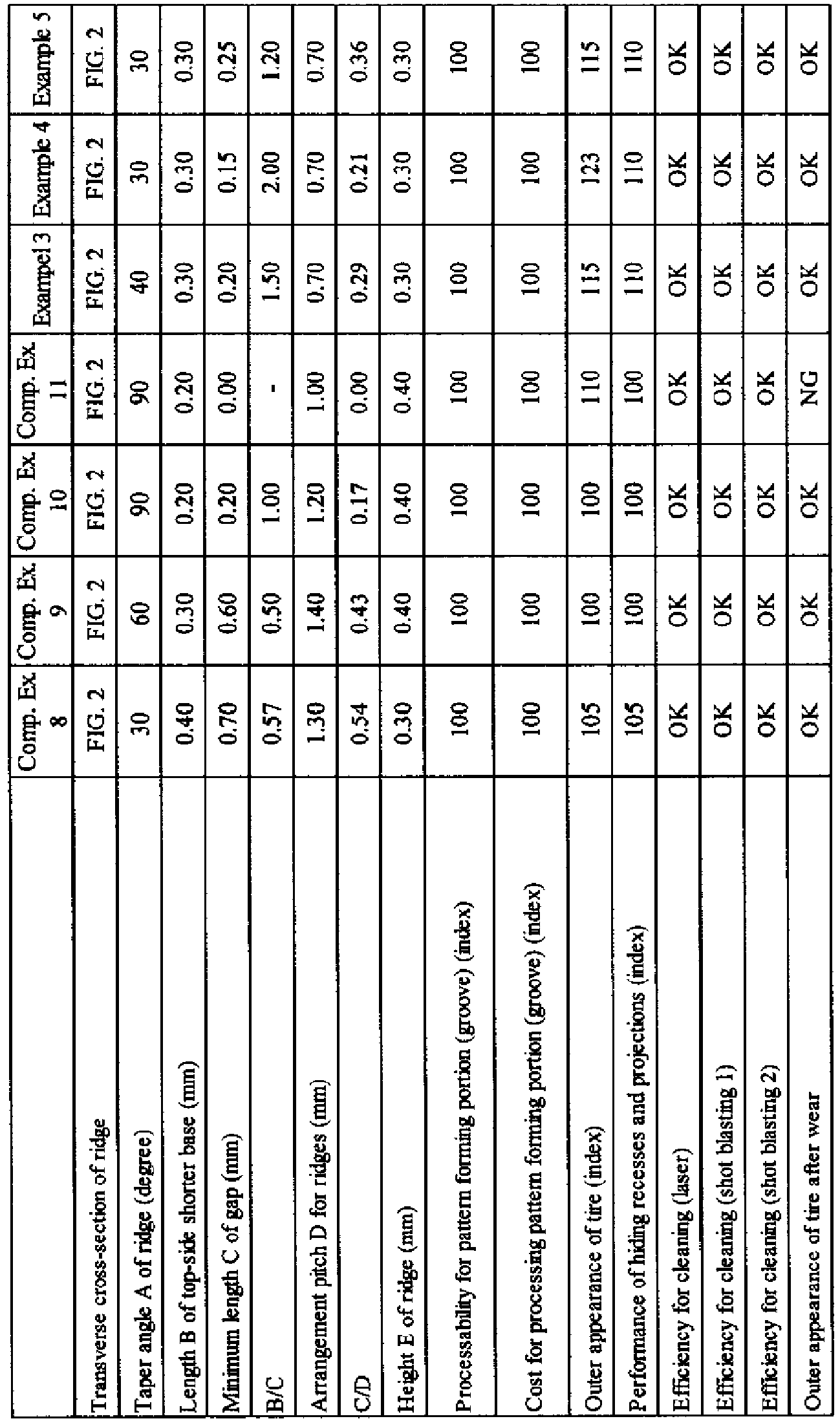
- Tires (size: 195/65R15) were produced as sample tires according to specifications indicated in Table 1 such that the decorative patterns were formed on surfaces of the sidewall portions (examples 1 to 8 and comparative examples 1 to 12).
- the tires of examples and comparative examples were each evaluated for processability for the pattern forming portion (groove) of the vulcanization mold, cost for processing the pattern forming portion of the vulcanization mold, outer appearance of the tire, performance of hiding recesses and projections, efficiency for cleaning the vulcanization mold, and outer appearance of the tire after the pattern forming portion of the vulcanization mold was worn.
- the evaluation methods are as follows.
- the evaluation is indicated as an index with the index of example 2 being 100. The greater the value of the index is, the better the evaluation is.
- Clarity of contrast of light at the decorative pattern was evaluated through visual inspection by a tester when the tire was viewed from the side surface in a state where each tire was inflated to an internal pressure of 200 kPa.
- the evaluation is indicated as an index with the index of comparative example 10 being 100. The greater the value of the index is, the better the evaluation is.
- Inconspicuousness of recesses and projections formed in the sidewall portion was evaluated through visual inspection by a tester in a state where each tire was inflated to an internal pressure of 200 kPa.
- the evaluation is indicated as an index with the index of comparative example 10 being 100. The greater the value of the index is, the better the evaluation is.
- Easiness of cleaning the pattern forming portion (groove) of the vulcanization mold was evaluated by using a laser cleaning device and shot blasting devices 1, 2 after each tire was vulcanized and molded.
- "OK” represents a case where the cleaning was able to be performed
- "NG” represents a case where the cleaning was difficult.
- Particles and particle diameters in the shot blasting devices 1, 2 are as follows.
Landscapes
- Engineering & Computer Science (AREA)
- Mechanical Engineering (AREA)
- Tires In General (AREA)
- Moulds For Moulding Plastics Or The Like (AREA)
Description
- The present invention relates to a tire having a decorative pattern formed on a surface of a sidewall portion.
- In general, a sidewall portion of a tire has thin rubber, and, therefore, recesses and projections called dents and bulges become conspicuous due to, for example, residual air and a joint portion of a carcass that is an internal structure. Such recesses and projections deteriorate outer appearance of the tire.
- Japanese Laid-Open Patent Publication No.
7-164831 - A tire in accordance with the preamble of
claim 1 is known from documentJP 2017 001438 A - In order to make the recesses and projections less conspicuous, it is important to form a gap between the adjacent ridges so as to make the gap small, form the gap portion so as to be viewed as being dark (black), and clarify contrast of light on the strip-like design.
- However, when the gap formed between adjacent ridges is made small, multiple ridges are formed in the tire circumferential direction. According thereto, a proportion of groove portions formed in a molding surface of a vulcanization mold is also increased. Laser, particles, or the like used for cleaning the molding surface are unlikely to be easily applied into the groove portions. Therefore, a problem arises that efficiency for cleaning the vulcanization mold is reduced. Accordingly, there is room for further improvement in that both outer appearance of the tire and efficiency for cleaning the vulcanization mold are to be improved.
- The present invention is made in view of the aforementioned circumstance, and a main object of the present invention is to provide a tire that allows improvement of both outer appearance of the tire and efficiency for cleaning a vulcanization mold.
- This object is solved by a tire having the features of
claim 1. - Subclaims are directed to preferred embodiments.
- In the tire of the present invention, the decorative pattern is formed on the surface of the sidewall portion. The decorative pattern is formed such that a plurality of ridges that extend in the tire radial direction are aligned in the tire circumferential direction so as to form the gaps. The decorative pattern having such a structure can prevent recesses and projections on the sidewall portion from becoming conspicuous, and can improve outer appearance of the tire.
- The transverse cross-section of the ridge is tapered so as to gradually reduce the length along the surface such that the greater the distance from the surface is, the less the length along the surface is. The decorative pattern is structured so as to satisfy expressions (E1) and (E2).


- The decorative pattern is formed such that the taper angle A of the ridge is not greater than 40 degrees. Therefore, an incident angle and a reflection angle of light that is incident so as to be perpendicular to the surface can be reduced at the side surface of the ridge. Thus, the decorative pattern allows reflection from the side surface toward the outside of the tire to be weakened. Furthermore, the decorative pattern is formed such that the minimum length C of the gap is not greater than 0.25 mm, and thus allows reflection from the surface toward the outside of the tire to be weakened. Thus, the decorative pattern allows the gap to be viewed as being darker (black) and allows contrast of light between the ridge and the gap to be clarified. Thus, the recesses and projections can be further inhibited from becoming conspicuous.
- Meanwhile, the decorative pattern is formed such that taper angle A is not less than 20 degrees, and, thus, the wall surface of the groove portion (reversed pattern of the ridge), of the vulcanization mold, for forming the ridge can be appropriately expanded. Therefore, laser, particles, and the like can be easily applied into the groove portions when the mold is cleaned. Furthermore, the decorative pattern is formed such that the minimum length C of the gap is not less than 0.15 mm, and, thus, the number of the ridges in the tire circumferential direction is prevented from excessively increasing. Thus, in the present invention, the proportion of the groove portions is reduced, and efficiency for cleaning the vulcanization mold can be improved while the recesses and projections are inhibited from becoming conspicuous.
-
-
FIG. 1 is a partial side view of an example of a tire; -
FIG 2 is a cross-sectional view taken along a line A-A inFIG 1 ; -
FIG 3 is a partial cross-sectional view of examples of a vulcanization mold and a green tire in a vulcanization step; -
FIG. 4 is a cross-sectional view of an example of a decorative pattern according to another embodiment of the present invention; and -
FIG. 5 is a partial cross-sectional view of examples of a vulcanization mold and a green tire in a vulcanization step, according to another embodiment of the present invention. - Hereinafter, an embodiment of the present invention will be described with reference to the drawings.
-
FIG. 1 is a partial side view of an example of a tire. Atire 1 of the present embodiment includes: atread portion 2; a pair ofsidewall portions 3 that extend from both side ends of thetread portion 2 in the radially inward direction of the tire; and beadportions 4 that are continuous with inner portions of thesidewall portions 3 in the tire radial direction. In the present embodiment, thetire 1 for a passenger car is described as an example. However, thetire 1 is not limited to such a tire, and may be, for example, a two-wheeled automotive vehicle tire or a heavy duty tire. - In the description herein, unless otherwise specified, dimensions and the like of components of the
tire 1 represent values measured in a state (normal state) in which thetire 1 is mounted on a normal rim (not shown) and is inflated to a normal internal pressure, and no load is applied to the tire. - The "normal rim" represents a rim that is defined by a standard, in a standard system including the standard with which the tire complies, for each tire, and is, for example, the "standard rim" in the JATMA standard, the "Design Rim" in the TRA standard, or the "Measuring Rim" in the ETRTO standard.
- The "normal internal pressure" represents an air pressure that is defined by the standard for each tire, and is the "maximum air pressure" in the JATMA standard, the maximum value recited in the table "TIRE LOAD LIMITS AT VARIOUS COLD INFLATION PRESSURES" in the TRA standard, or the "INFLATION PRESSURE" in the ETRTO standard. In the case of a tire for a passenger car, the normal internal pressure is 180 kPa.
- The
tire 1 of the present embodiment has adecorative pattern 7 formed on asurface 5 of thesidewall portion 3. In the present embodiment, thedecorative pattern 7 is formed so as to be annular as viewed from the side surface of thetire 1. However, thedecorative pattern 7 is not limited to such a mode. Thedecorative pattern 7 may be, for example, formed in a strip-like shape in which both ends in the tire circumferential direction are disconnected, or thedecorative patterns 7 may be disposed at intervals in the tire circumferential direction. Furthermore, for example, characters (not shown) representing a logo mark, a brand name, or the like of thetire 1 may be formed on thedecorative pattern 7 so as to be, for example, relief. A length L1 of thedecorative pattern 7 in the tire radial direction is not particularly limited. In the present embodiment, the length L1 is preferably about 5 to 30% of the tire cross-sectional height. -
FIG 2 is a cross-sectional view taken along a line A-A inFIG. 1 .FIG 3 is a partial cross-sectional view of an example of apattern forming portion 24 in avulcanization mold 21. As shown inFIG. 2 , thedecorative pattern 7 is formed such that a plurality ofridges 11 that extend in the tire radial direction are aligned in the tire circumferential direction so as to formgaps 12 therebetween. Thedecorative pattern 7 having such a structure is formed by groove portions (reversed patterns of the ridges 11) 25 of thepattern forming portions 24 in amolding surface 23 of thevulcanization mold 21, shown inFIG. 3 , for the tire as in a conventional art. - As shown in
FIG. 1 andFIG. 2 , eachridge 11 is formed as a raised-line-like projection that projects from thesurface 5 of thesidewall portion 3 and extends in the tire radial direction. As shown inFIG. 2 , the transverse cross-section of theridge 11 is tapered so as to gradually reduce a length L2 along thesurface 5 such that the greater the distance from thesurface 5 of thesidewall portion 3 is, the less the length L2 along thesurface 5 is. - In the present embodiment, the transverse cross-section of the
ridge 11 has a top-sideshorter base 15 that extends along thesurface 5, at a position that is farthest from thesurface 5. Thus, the transverse cross-section of theridge 11 is formed in a trapezoidal shape which has the top-sideshorter base 15 and a pair ofside surfaces shorter base 15 to thesurface 5. In the drawings,corner portions 17 of theridge 11 are illustrated as sharp edges. However, examples of the "trapezoidal shape" include a shape in which thecorner portion 17 has a chamfered portion having a small curvature radius, in consideration of the size of theridge 11 and a rubber molding technique. - The
decorative pattern 7 having such a structure allows thegap 12 between theadjacent ridges ridges 11 and thegaps 12 to be clarified. Thus, thedecorative pattern 7 can function to hide the recesses and projections (dents and bulges) caused by, for example, residual air and a joint portion of a carcass (not shown) which is an internal structure of thetire 1, so as to inhibit the recesses and projections (dents and bulges) from becoming conspicuous, whereby thedecorative pattern 7 contributes to improvement of outer appearance of thetire 1. - The decorative pattern 7 (shown in
FIG. 2 ) of the present embodiment is structured so as to satisfy the following expressions (E1) and (E2).

ridge 11, and C represents a minimum length (mm), of thegap 12, measured along thesurface 5. - According to expression (E1), the taper angle A of the
ridge 11 is set to be not greater than 40 degrees. In general, the outer appearance as viewed from the front thereof is particularly important in order to improve the outer appearance of thesidewall portion 3 of thetire 1. In the decorative pattern of the present embodiment, the taper angle A of theridge 11 is not greater than 40 degrees, and, thus, an incident angle θ1 and a reflection angle θ2 of light 30 (indicated by an alternate long and two short dashes line inFIG. 2 ) which is incident so as to be perpendicular (along the tire axial direction) to thesurface 5 of thesidewall portion 3 can be reduced at theside surface 16 of theridge 11. Therefore, at thedecorative pattern 7, reflection from theside surface 16 of theridge 11 toward the outside of thetire 1 can be weakened. - Furthermore, on wall surfaces (that is, side surface forming portions for forming the side surfaces 16 of the ridge 11) 28, 28 of the
groove portion 25, of thevulcanization mold 21, for forming theridge 11 as shown inFIG. 3 , incident angles and reflection angles of laser and particles used for cleaning thevulcanization mold 21 can be reduced. Thus, diffuse reflection of laser and particles can be caused in thegroove portion 25, whereby dirt attached to thegroove portion 25 can be efficiently removed. - According to expression (E2), the minimum length C of the
gap 12 is set to be not greater than 0.25 mm. Thus, thedecorative pattern 7 of the present embodiment allows reflection from thesurface 5 of thesidewall portion 3 toward the outside of thetire 1 to be weakened. Therefore, thedecorative pattern 7 of the present embodiment allows thegap 12 to be viewed as being darker (black), and allows contrast of light between theridge 11 and thegap 12 to be clarified. Accordingly, thedecorative pattern 7 allows the outer appearance of thetire 1 to be improved since the recesses and projections (not shown) formed in thesidewall portion 3 are made less conspicuous. - Meanwhile, when the taper angle A of the
ridge 11 and the minimum length C of thegap 12 are reduced,multiple ridges 11 are formed in the tire circumferential direction. According thereto, a proportion (the number) of thegroove portions 25 formed in themolding surface 23 of thevulcanization mold 21 shown inFIG. 3 is also increased. Laser, particles, and the like used for cleaning themolding surface 23 are not easily applied into thegroove portions 25, so that efficiency for cleaning the vulcanization mold is reduced. - In the present embodiment, according to expression (E1), the taper angle A is set to be not less than 20 degrees. Thus, as shown in
FIG. 3 , in the present embodiment, at least one (in the present embodiment, both) of the wall surfaces 28 and 28 of thegroove portion 25, of thevulcanization mold 21, for forming theridge 11 can be appropriately expanded in the tire circumferential direction. Therefore, in the present embodiment, when the mold is cleaned, laser, particles, and the like can be easily applied into thegroove portion 25 of thevulcanization mold 21. - Furthermore, according to expression (E2), the minimum length C of the
gap 12 is set to be not less than 0.15 mm. Thus, in thedecorative pattern 7 of the present embodiment, the number of theridges 11 can be prevented from being excessively increased in the tire circumferential direction. Therefore, in the present embodiment, the proportion of thegroove portions 25 of thevulcanization mold 21 can be reduced, thereby improving efficiency for the cleaning. - Thus, in the
tire 1 of the present embodiment, thedecorative pattern 7 satisfies expressions (E1) and (E2), whereby both the outer appearance of thetire 1 and efficiency for cleaning thevulcanization mold 21 can be improved. - When the taper angle A is greater than 40 degrees, the incident angle θ1 and the reflection angle θ2 of the light 30 described above are increased at the
side surface 16 of theridge 11. Therefore, reflection from theside surface 16 toward the outside of thetire 1 may not be weakened. Furthermore, on the wall surfaces 28, 28 of thegroove portion 25, of thevulcanization mold 21, for forming theridge 11 as shown inFIG. 3 , the incident angles and the reflection angles of laser and particles used for cleaning thevulcanization mold 21 may be increased, and dirt attached to thegrove portion 25 may not be efficiently removed. - Meanwhile, when the taper angle A is less than 20 degrees, the wall surfaces 28, 28 of the
groove portion 25 cannot be expanded, and efficiency for the cleaning may be reduced in the case of the mold being cleaned. Furthermore, the wall surfaces 28, 28 of thegroove portion 25 contact with abottom surface 27 for forming the top-sideshorter base 15 of theridge 11, at large angles. Therefore, processability for thegroove portion 25 may be reduced, and cost for processing thepattern forming portion 24 may be increased. From such a viewpoint, the taper angle A is preferably not less than 25 degrees and preferably not greater than 35 degrees. - When the minimum length C of the
gap 12 is greater than 0.25 mm, reflection from thesurface 5 of thesidewall portion 3 toward the outside of thetire 1 is increased. Therefore, contrast of light between theridge 11 and thegap 12 cannot be clarified, and the outer appearance of thetire 1 may be deteriorated. Meanwhile, when the minimum length C of thegap 12 is less than 0.15 mm, the proportion of thegroove portions 25 of thevulcanization mold 21 shown inFIG. 3 is increased, and efficiency for the cleaning may be reduced in the case of the mold being cleaned. Furthermore, when the width of themolding surface 23 between theadjacent groove portions pattern forming portion 24 may be increased, and themolding surface 23 may be worn early due to the cleaning. From such a viewpoint, the minimum length C of thegap 12 is preferably not less than 0.18 mm and preferably not greater than 0.22 mm. - In order to further facilitate application of laser, particles, and the like into the
groove portions 25 while contrast of light between theridge 11 and thegap 12 is enhanced, thedecorative pattern 7 of the present embodiment is structured so as to satisfy expressions (E1) and (E2) described above, and to satisfy the following expression (E3),

shorter base 15, measured along thesurface 5, and D represents an arrangement pitch at which theridges 11 are arranged in the tire circumferential direction. - According to expression (E3), a ratio C/D of the minimum length C of the
gap 12 to the arrangement pitch D for theridges 11 as shown inFIG. 2 is set to be not greater than 0.4. Thus, the minimum length C of thegap 12 can be formed so as to be sufficiently small relative to the arrangement pitch D for theridges 11, and reflection from thesurface 5 of thesidewall portion 3 toward the outside of thetire 1 can be further weakened. - According to expression (E4), a ratio B/C of the length B of the top-side
shorter base 15 to the minimum length C of thegap 12 is set to be not greater than 3. Thus, the top-sideshorter base 15 can be prevented from being excessively great relative to the gap 12 (surface 5). Therefore, in thedecorative pattern 7, the top-sideshorter base 15 which is viewed as being bright (white) and thegap 12 which is viewed as being dark (black) are formed in a well-balanced manner. Thus, contrast of light between theridge 11 and thegap 12 can be further enhanced, and the outer appearance of thetire 1 can be further improved. - According to expression (E3), the ratio C/D of the minimum length C of the
gap 12 to the arrangement pitch D for theridges 11 is set to be not less than 0.2. Thus, the width of themolding surface 23 between theadjacent groove portions pattern forming portion 24 can be effectively prevented from increasing, and themolding surface 23 can be effectively prevented from being worn early due to the cleaning. - According to expression (E4), the ratio B/C of the length B of the top-side
shorter base 15 to the minimum length C of thegap 12 is set to be not less than 1. Thus, in the present embodiment, the length of thebottom surface 27 of thegroove portion 25 of thevulcanization mold 21 can be increased in the tire circumferential direction. Therefore, in the present embodiment, laser, particles, and the like can be more easily applied into thegroove portions 25 when the mold is cleaned. - Thus, the
decorative pattern 7 of the present embodiment satisfies expressions (E1) and (E2) and further satisfies expressions (E3) and (E4), whereby both the outer appearance of thetire 1 and efficiency for cleaning thevulcanization mold 21 can be improved at a higher level. - When the ratio C/D of the minimum length C of the
gap 12 to the arrangement pitch D for theridges 11 is greater than 0.4, the minimum length C of thegap 12 is increased relative to the arrangement pitch D for theridges 11. Therefore, reflection from thesurface 5 of thesidewall portion 3 toward the outside of thetire 1 may not be sufficiently weakened. Meanwhile, when the ratio C/D is less than 0.2, the width of themolding surface 23 between theadjacent groove portions pattern forming portion 24 may not be sufficiently prevented from increasing and themolding surface 23 may not be sufficiently prevented from being worn early due to the cleaning. From such a viewpoint, the ratio C/D is preferably not less than 0.25 and preferably not greater than 0.35. - When the ratio B/C of the length B of the top-side
shorter base 15 to the minimum length C of thegap 12 is greater than 3, the top-sideshorter base 15 is large in the tire circumferential direction relative to thegap 12 shown inFIG. 2 , and contrast of light between theridge 11 and thegap 12 may not be sufficiently enhanced. Meanwhile, when the ratio B/C is less than 1, thebottom surface 27 of thegroove portion 25 of thevulcanization mold 21 shown inFIG.3 is small, and laser, particles, and the like may not be easily applied into thegroove portions 25. Furthermore, cost for processing thepattern forming portion 24 may be increased. From such a viewpoint, the ratio B/C is preferably not less than 1.5 and preferably not greater than 2.5. - The arrangement pitch D for the
ridges 11 is set as appropriate when expression (E3) is satisfied. However, the arrangement pitch D for theridges 11 is preferably set to be 0.13 to 2.1 mm. When the arrangement pitch D is set to be not less than 0.13 mm, the number of theridges 11 can be prevented from increasing, and the proportion of thegroove portions 25 of thevulcanization mold 21 can be reduced. Therefore, efficiency for the cleaning can be further improved when the mold is cleaned. - When the arrangement pitch D is set to be not greater than 2.1 mm, at least one of the top-side
shorter base 15 and thegap 12 shown inFIG. 2 can be prevented from being large, so that contrast between theridge 11 and thegap 12 can be further enhanced. From such a viewpoint, the arrangement pitch D is more preferably not less than 0.3 mm and more preferably not greater than 1.9 mm. - The length B of the top-side
shorter base 15 can be set as appropriate when expression (E4) is satisfied. However, the length B of the top-sideshorter base 15 is preferably set to be 0.05 to 0.40 mm. When the length B of the top-sideshorter base 15 is not less than 0.05 mm, thebottom surface 27 of thegroove portions 25 of thevulcanization mold 21 shown inFIG 3 can be made large, and efficiency for the cleaning can be further improved when the mold is cleaned. - When the length B of the top-side
shorter base 15 is not greater than 0.40 mm, the top-sideshorter base 15 and thegap 12 shown inFIG. 2 are formed in a well-balanced manner. Therefore, contrast of light between theridge 11 and thegap 12 can be further enhanced. From such a viewpoint, the length B of the top-sideshorter base 15 is more preferably not less than 0.10 mm and more preferably not greater than 0.35 mm. - A height E of the
ridge 11 from thesurface 5 of thesidewall portion 3 can be set as appropriate. However, the height E of theridge 11 is preferably set to be 0.1 to 0.5 mm. When the height E of theridge 11 is not less than 0.1 mm, thegap 12 can be viewed as being darker (black). When the height E of theridge 11 is not greater than 0.5 mm, thegroove portions 25 of thevulcanization mold 21 shown inFIG. 3 can be prevented from being deepened. Therefore, efficiency for the cleaning can be further improved. From such a viewpoint, the height E is more preferably not less than 0.15 mm and more preferably not greater than 0.45 mm. - A case where the transverse cross-section of the
ridge 11 has a trapezoidal shape having the top-sideshorter base 15 is described as an example in the above-described embodiment. However, the present invention is not limited to such an example.FIG. 4 is a cross-sectional view of an example of thedecorative pattern 7 according to another embodiment of the present invention.FIG. 5 is a partial cross-sectional view of an example of thepattern forming portion 24 according to another embodiment of the present invention. In the present embodiment, the same components as in the above-described embodiment are denoted by the same reference numerals, and the description thereof may be omitted. - In the present embodiment, the transverse cross-section of the
ridge 11 is formed in a triangular shape having avertex 35 at a position farthest from thesurface 5 of thesidewall portion 3. Furthermore, the transverse cross-section of theridge 11 has a pair of side surfaces 16, 16 that extend from thevertex 35 to thesurface 5. Examples of the triangular shape include a shape in which a part of thevertex 35 of the triangular shape has a small chamfered portion, in consideration of the size of theridge 11 and a rubber forming technique. - The
decorative pattern 7 of the present embodiment can function to hide recesses and projections (not shown) formed in thesidewall portion 3 so as to inhibit the recesses and projections from becoming conspicuous, similarly to thedecorative pattern 7 of the above-described embodiment. Furthermore, in thedecorative pattern 7 of the present embodiment, theridge 11 has a triangular transverse cross-section, and, thus, thevertex 35 of eachridge 11 can be formed so as to be sharp and have a good appearance. Therefore, thedecorative pattern 7 contributes to improvement of the outer appearance of thetire 1. - The
decorative pattern 7 of the present embodiment is structured such that the taper angle A of theridge 11 and the minimum length C of thegap 12 satisfy expressions (E1) and (E2) described above. Thus, thedecorative pattern 7 of the present embodiment allows improvement of both the outer appearance of thetire 1 and efficiency for cleaning thevulcanization mold 21 shown inFIG. 5 , similarly to thedecorative pattern 7 of the above-described embodiment. Preferable ranges of the taper angle A and the minimum length C are the same as the preferable ranges of the taper angle A and the minimum length C in the above-described embodiment. - Furthermore, the
decorative pattern 7 of the present embodiment is structured so as to satisfy expressions (E1) and (E2) described above, and to satisfy the expression (E3).
ridges 11 are arranged in the tire circumferential direction. - Expression (E3) defines a range of the ratio C/D of the minimum length C of the
gap 12 to the arrangement pitch D for theridges 11, similarly to expression (E3) of the above-described embodiment. Thus, laser, particles, and the like can be more easily applied into thegroove portions 25 while contrast of light between theridge 11 and thegap 12 is further enhanced. - Thus, when the
decorative pattern 7 of the present embodiment satisfies expressions (E1) and (E2) described above, and further satisfies expression (E3), both the outer appearance of thetire 1 and efficiency for cleaning thevulcanization mold 21 can be improved at a higher level. Preferable ranges of the ratio C/D of the minimum length C of thegap 12 to the arrangement pitch D for theridges 11, and the arrangement pitch D for theridges 11 are the same as the preferable ranges of the ratio C/D and the arrangement pitch D, respectively, of the above-described embodiment. - As shown in
FIG. 4 , in theridge 11, oneside surface 16a of the pairedside surfaces surface 5 of thesidewall portion 3. Thus, the transverse cross-section of theridge 11 of the present embodiment is shaped into a right triangle. - The
ridge 11 having such a structure allows an incident angle (not shown) and a reflection angle (not shown) of the light 30 (indicated by an alternate long and two short dashes line inFIG 4 ) described above to be almost zero at the oneside surface 16a. Thus, thedecorative pattern 7 allows reflection from the oneside surface 16a toward the outside of thetire 1 to be effectively weakened. Meanwhile, an incident angle θ1 and a reflection angle θ2 of the light 30 can be slightly increased at theother side surface 16b which is not orthogonal to thesurface 5, as compared to the above-described embodiment. Thus, thedecorative pattern 7 allows reflection from theother side surface 16b toward the outside of thetire 1 to be slightly enhanced. Therefore, thedecorative pattern 7 of the present embodiment allows the intensity of the reflection to be made different among the side surfaces 16a and 16b, and thesurface 5, to diversify contrast of light. Therefore, the outer appearance of the tire can be improved. - The
decorative pattern 7 structured such that theridge 11 has the trapezoidal transverse cross-section (shown inFIG. 2 ) and thedecorative pattern 7 structured such that theridge 11 has the triangular transverse cross-section (shown inFIG 4 ) are illustrated for these embodiments. However, the present invention is not limited thereto. Thedecorative pattern 7 may be structured by, for example, theridge 11 having a trapezoidal transverse cross-section and theridge 11 having a triangular transverse cross-section being used in combination. Thus, thedecorative pattern 7 allows diversity of contrast of light to be further improved, thereby further improving the outer appearance of thetire 1. - Although the preferred embodiments of the present invention have been described in detail above, the present invention is not limited to the above-described embodiments shown in the drawings, and various modifications can be made to practice the present invention.
- Tires (size: 195/65R15) were produced as sample tires according to specifications indicated in Table 1 such that the decorative patterns were formed on surfaces of the sidewall portions (examples 1 to 8 and comparative examples 1 to 12). The tires of examples and comparative examples were each evaluated for processability for the pattern forming portion (groove) of the vulcanization mold, cost for processing the pattern forming portion of the vulcanization mold, outer appearance of the tire, performance of hiding recesses and projections, efficiency for cleaning the vulcanization mold, and outer appearance of the tire after the pattern forming portion of the vulcanization mold was worn. The evaluation methods are as follows.
- A time and cost required for processing the pattern forming portion (groove) of the vulcanization mold, in the molding surface of the vulcanization mold, were obtained. The evaluation is indicated as an index with the index of example 2 being 100. The greater the value of the index is, the better the evaluation is.
- Clarity of contrast of light at the decorative pattern was evaluated through visual inspection by a tester when the tire was viewed from the side surface in a state where each tire was inflated to an internal pressure of 200 kPa. The evaluation is indicated as an index with the index of comparative example 10 being 100. The greater the value of the index is, the better the evaluation is.
- Inconspicuousness of recesses and projections formed in the sidewall portion was evaluated through visual inspection by a tester in a state where each tire was inflated to an internal pressure of 200 kPa. The evaluation is indicated as an index with the index of comparative example 10 being 100. The greater the value of the index is, the better the evaluation is.
- Easiness of cleaning the pattern forming portion (groove) of the vulcanization mold was evaluated by using a laser cleaning device and shot
blasting devices shot blasting devices - Shot blasting device 1: particle: steel, particle diameter: 0.044 to 0.1 mm
- Shot blasting device 2: particle: plastic, particle diameter: 0.17 to 0.5 mm
- After particles for three years were applied to the pattern forming portion (groove) of the vulcanization mold by using the
shot blasting device 1, each tire was produced by using the vulcanization mold. Clarity of contrast of light at the decorative pattern was evaluated through visual inspection by a tester when each tire was viewed from the side surface in a state where the tire was inflated to an internal pressure of 200 kPa. In the evaluation, "OK" represents a case where almost no change occurred between a state where the pattern forming portion was worn and a state where the pattern forming portion was not worn, and "NG" represents a case where change was great therebetween. The results of the test are indicated in Table 1.



Claims (9)
- A tire (1) comprising
a decorative pattern (7) formed on a surface (5) of a sidewall portion (3), wherein
the decorative pattern (7) is formed such that a plurality of ridges (11) that extend in a tire radial direction are aligned in a tire circumferential direction so as to form gaps (12),
a transverse cross-section of each ridge (11) is tapered so as to gradually reduce a length (L2) parallel to the surface (5) such that the greater a distance from the surface (5) is, the less the length (L2) 2. parallel to the surface (5) is, and
the decorative pattern (7) is structured so as to satisfy expression (E1),
characterized in that
the decorative pattern (7) is structured so as to further satisfy expressions (E2) and (E3),

- The tire (1) according to claim 1, wherein
the transverse cross-section of the ridge (11) has a top-side shorter base (15) that extends parallel to the surface, at a position that is farthest from the surface (5), and
the decorative pattern (7) is structured so as to further satisfy expression (E4),
- The tire (1) according to claim 2, wherein the arrangement pitch D for the ridges (11) is 0.13 to 2.1 mm.
- The tire (1) according to claim 2 or 3, wherein the length B of the top-side shorter base (15) is 0.05 to 0.4 mm.
- The tire (1) according to claim 1, wherein
the transverse cross-section of the ridge (11) has a triangular shape having a vertex (35) at a position that is farthest from the surface (5). - The tire (1) according to claim 5, wherein one of paired side surfaces (16a, 16b) that extend from the vertex (35) to the surface (5) is orthogonal to the surface.
- The tire (1) according to any one of claims 1 to 6, wherein a height (E) of the ridge (11) from the surface is 0.1 to 0.5 mm.
- The tire (1) according to claim 5, wherein
the triangular shape is a right triangle. - The tire (1) according to claim 1, wherein
the decorative pattern (7) is structured by ridges (11) having a trapezoidal transverse cross-section and ridges (11) having a triangular transverse cross-section being used in combination.
Applications Claiming Priority (1)
| Application Number | Priority Date | Filing Date | Title |
|---|---|---|---|
| JP2018130911A JP7151226B2 (en) | 2018-07-10 | 2018-07-10 | tire |
Publications (3)
| Publication Number | Publication Date |
|---|---|
| EP3594024A1 EP3594024A1 (en) | 2020-01-15 |
| EP3594024B1 true EP3594024B1 (en) | 2021-03-24 |
| EP3594024B9 EP3594024B9 (en) | 2021-08-18 |
Family
ID=67105865
Family Applications (1)
| Application Number | Title | Priority Date | Filing Date |
|---|---|---|---|
| EP19182862.3A Active EP3594024B9 (en) | 2018-07-10 | 2019-06-27 | Tire |
Country Status (4)
| Country | Link |
|---|---|
| US (1) | US11518197B2 (en) |
| EP (1) | EP3594024B9 (en) |
| JP (1) | JP7151226B2 (en) |
| CN (1) | CN110696563B (en) |
Families Citing this family (12)
| Publication number | Priority date | Publication date | Assignee | Title |
|---|---|---|---|---|
| JP7230731B2 (en) * | 2019-08-05 | 2023-03-01 | 横浜ゴム株式会社 | pneumatic tire |
| JP7207224B2 (en) * | 2019-08-05 | 2023-01-18 | 横浜ゴム株式会社 | pneumatic tire |
| DE112020007427B4 (en) * | 2019-08-05 | 2024-08-08 | The Yokohama Rubber Co., Ltd. | tire |
| JP7124807B2 (en) * | 2019-08-05 | 2022-08-24 | 横浜ゴム株式会社 | pneumatic tire |
| JP7650759B2 (en) * | 2021-08-27 | 2025-03-25 | Toyo Tire株式会社 | Pneumatic tires |
| JP7650755B2 (en) * | 2021-08-27 | 2025-03-25 | Toyo Tire株式会社 | Pneumatic tires |
| EP4140781B1 (en) * | 2021-08-27 | 2024-04-03 | Toyo Tire Corporation | Pneumatic tire |
| JP7650754B2 (en) * | 2021-08-27 | 2025-03-25 | Toyo Tire株式会社 | Pneumatic tires |
| CN115257242A (en) * | 2022-07-28 | 2022-11-01 | 山东玲珑轮胎股份有限公司 | Tire with side wall provided with texture decorative patterns |
| JP2024031179A (en) * | 2022-08-26 | 2024-03-07 | 住友ゴム工業株式会社 | tire |
| JP2024082400A (en) * | 2022-12-08 | 2024-06-20 | 横浜ゴム株式会社 | Tires and tire moulds |
| JP7671890B1 (en) * | 2024-02-21 | 2025-05-02 | Toyo Tire株式会社 | Pneumatic tire and mold for molding pneumatic tire |
Family Cites Families (23)
| Publication number | Priority date | Publication date | Assignee | Title |
|---|---|---|---|---|
| JP3436401B2 (en) * | 1993-12-10 | 2003-08-11 | 株式会社ブリヂストン | Pneumatic tire with band design |
| JPH08282218A (en) * | 1995-04-11 | 1996-10-29 | Bridgestone Corp | Flat pneumatic tire having rim guard |
| JP3667818B2 (en) * | 1995-05-26 | 2005-07-06 | 株式会社ブリヂストン | Pneumatic tire with a decorative body consisting of many ridges |
| JP3007825B2 (en) * | 1995-09-28 | 2000-02-07 | 住友ゴム工業株式会社 | Pneumatic tire |
| US6253815B1 (en) * | 1998-08-14 | 2001-07-03 | Michelin Recherche Et Techniques S.A. | Design pattern for a tire |
| JP4315515B2 (en) * | 1999-03-30 | 2009-08-19 | 株式会社ブリヂストン | Pneumatic tire |
| FR2892336B1 (en) * | 2005-10-21 | 2009-10-09 | Michelin Soc Tech | MARKING PROVIDES IMPROVED VISIBILITY AND MARKING METHOD. |
| JP5193593B2 (en) * | 2007-12-28 | 2013-05-08 | 株式会社ブリヂストン | Pneumatic tire |
| WO2009084634A1 (en) * | 2007-12-28 | 2009-07-09 | Bridgestone Corporation | Pneumatic tire |
| JP2010285106A (en) * | 2009-06-12 | 2010-12-24 | Sumitomo Rubber Ind Ltd | Pneumatic tire and manufacturing method thereof |
| JP5445092B2 (en) | 2009-12-11 | 2014-03-19 | 横浜ゴム株式会社 | Pneumatic tire |
| JP5785530B2 (en) * | 2012-09-21 | 2015-09-30 | 住友ゴム工業株式会社 | Pneumatic tire |
| JP5519812B1 (en) * | 2013-01-09 | 2014-06-11 | 株式会社ブリヂストン | Pneumatic tire |
| JP5793159B2 (en) * | 2013-03-19 | 2015-10-14 | 住友ゴム工業株式会社 | Pneumatic tire |
| JP5756490B2 (en) * | 2013-03-26 | 2015-07-29 | 住友ゴム工業株式会社 | Pneumatic tire |
| EP3016809B1 (en) * | 2013-07-01 | 2019-08-21 | Bridgestone Americas Tire Operations, LLC | Methods and apparatuses for creating a visual effect on a rubber article |
| JP5782481B2 (en) * | 2013-07-05 | 2015-09-24 | 住友ゴム工業株式会社 | Pneumatic tire |
| FR3022851B1 (en) * | 2014-06-30 | 2018-05-11 | Compagnie Generale Des Etablissements Michelin | PNEUMATIC COMPRISING A HIGH CONTRAST MARKING |
| JP6034837B2 (en) * | 2014-09-17 | 2016-11-30 | 住友ゴム工業株式会社 | Pneumatic tire |
| JP6549412B2 (en) * | 2015-05-14 | 2019-07-24 | 株式会社ブリヂストン | tire |
| JP6441170B2 (en) | 2015-06-05 | 2018-12-19 | 株式会社ブリヂストン | tire |
| JP6694282B2 (en) * | 2016-01-27 | 2020-05-13 | 株式会社ブリヂストン | tire |
| JP6759903B2 (en) * | 2016-09-09 | 2020-09-23 | 住友ゴム工業株式会社 | Heavy load tires |
-
2018
- 2018-07-10 JP JP2018130911A patent/JP7151226B2/en active Active
-
2019
- 2019-05-07 CN CN201910374701.4A patent/CN110696563B/en active Active
- 2019-06-21 US US16/448,216 patent/US11518197B2/en active Active
- 2019-06-27 EP EP19182862.3A patent/EP3594024B9/en active Active
Non-Patent Citations (1)
| Title |
|---|
| None * |
Also Published As
| Publication number | Publication date |
|---|---|
| CN110696563B (en) | 2023-06-06 |
| EP3594024A1 (en) | 2020-01-15 |
| US20200016938A1 (en) | 2020-01-16 |
| EP3594024B9 (en) | 2021-08-18 |
| US11518197B2 (en) | 2022-12-06 |
| CN110696563A (en) | 2020-01-17 |
| JP7151226B2 (en) | 2022-10-12 |
| JP2020006863A (en) | 2020-01-16 |
Similar Documents
| Publication | Publication Date | Title |
|---|---|---|
| EP3594024B9 (en) | Tire | |
| US11325427B2 (en) | Tire | |
| US10675918B2 (en) | Pneumatic tire | |
| EP3275698B1 (en) | Pneumatic tire | |
| US20080128063A1 (en) | Pneumatic Tire | |
| US11628691B2 (en) | Tire | |
| KR101972174B1 (en) | Pneumatic tire | |
| JP6867115B2 (en) | Pneumatic tires | |
| JP5756490B2 (en) | Pneumatic tire | |
| KR102364115B1 (en) | Tire | |
| EP2813377A1 (en) | Pneumatic bias tire and manufacturing method for the same | |
| JP5802236B2 (en) | Pneumatic tire | |
| EP2468536A2 (en) | Pneumatic tire | |
| JP6111792B2 (en) | Pneumatic tire | |
| JP2013129233A (en) | Pneumatic tire and method for manufacturing the same | |
| US6681823B2 (en) | Heavy load pneumatic radial tire | |
| JP4973020B2 (en) | Pneumatic tire | |
| CN100464997C (en) | Pneumatic tire | |
| US20220339970A1 (en) | Pneumatic tire | |
| CN108146153B (en) | Pneumatic tire | |
| WO2024122234A1 (en) | Tire and tire mold | |
| JP2005138609A (en) | Pneumatic tire | |
| JP3124635U (en) | Pneumatic tire | |
| JP2013233854A (en) | Pneumatic tire | |
| JP2024082400A (en) | Tires and tire moulds |
Legal Events
| Date | Code | Title | Description |
|---|---|---|---|
| PUAI | Public reference made under article 153(3) epc to a published international application that has entered the european phase |
Free format text: ORIGINAL CODE: 0009012 |
|
| STAA | Information on the status of an ep patent application or granted ep patent |
Free format text: STATUS: THE APPLICATION HAS BEEN PUBLISHED |
|
| AK | Designated contracting states |
Kind code of ref document: A1 Designated state(s): AL AT BE BG CH CY CZ DE DK EE ES FI FR GB GR HR HU IE IS IT LI LT LU LV MC MK MT NL NO PL PT RO RS SE SI SK SM TR |
|
| AX | Request for extension of the european patent |
Extension state: BA ME |
|
| STAA | Information on the status of an ep patent application or granted ep patent |
Free format text: STATUS: REQUEST FOR EXAMINATION WAS MADE |
|
| 17P | Request for examination filed |
Effective date: 20200706 |
|
| RBV | Designated contracting states (corrected) |
Designated state(s): AL AT BE BG CH CY CZ DE DK EE ES FI FR GB GR HR HU IE IS IT LI LT LU LV MC MK MT NL NO PL PT RO RS SE SI SK SM TR |
|
| GRAP | Despatch of communication of intention to grant a patent |
Free format text: ORIGINAL CODE: EPIDOSNIGR1 |
|
| STAA | Information on the status of an ep patent application or granted ep patent |
Free format text: STATUS: GRANT OF PATENT IS INTENDED |
|
| INTG | Intention to grant announced |
Effective date: 20201104 |
|
| GRAS | Grant fee paid |
Free format text: ORIGINAL CODE: EPIDOSNIGR3 |
|
| GRAA | (expected) grant |
Free format text: ORIGINAL CODE: 0009210 |
|
| STAA | Information on the status of an ep patent application or granted ep patent |
Free format text: STATUS: THE PATENT HAS BEEN GRANTED |
|
| AK | Designated contracting states |
Kind code of ref document: B1 Designated state(s): AL AT BE BG CH CY CZ DE DK EE ES FI FR GB GR HR HU IE IS IT LI LT LU LV MC MK MT NL NO PL PT RO RS SE SI SK SM TR |
|
| REG | Reference to a national code |
Ref country code: GB Ref legal event code: FG4D |
|
| REG | Reference to a national code |
Ref country code: CH Ref legal event code: EP |
|
| REG | Reference to a national code |
Ref country code: IE Ref legal event code: FG4D |
|
| REG | Reference to a national code |
Ref country code: DE Ref legal event code: R096 Ref document number: 602019003381 Country of ref document: DE Ref country code: AT Ref legal event code: REF Ref document number: 1374118 Country of ref document: AT Kind code of ref document: T Effective date: 20210415 |
|
| REG | Reference to a national code |
Ref country code: LT Ref legal event code: MG9D |
|
| PG25 | Lapsed in a contracting state [announced via postgrant information from national office to epo] |
Ref country code: BG Free format text: LAPSE BECAUSE OF FAILURE TO SUBMIT A TRANSLATION OF THE DESCRIPTION OR TO PAY THE FEE WITHIN THE PRESCRIBED TIME-LIMIT Effective date: 20210624 Ref country code: HR Free format text: LAPSE BECAUSE OF FAILURE TO SUBMIT A TRANSLATION OF THE DESCRIPTION OR TO PAY THE FEE WITHIN THE PRESCRIBED TIME-LIMIT Effective date: 20210324 Ref country code: GR Free format text: LAPSE BECAUSE OF FAILURE TO SUBMIT A TRANSLATION OF THE DESCRIPTION OR TO PAY THE FEE WITHIN THE PRESCRIBED TIME-LIMIT Effective date: 20210625 Ref country code: FI Free format text: LAPSE BECAUSE OF FAILURE TO SUBMIT A TRANSLATION OF THE DESCRIPTION OR TO PAY THE FEE WITHIN THE PRESCRIBED TIME-LIMIT Effective date: 20210324 Ref country code: NO Free format text: LAPSE BECAUSE OF FAILURE TO SUBMIT A TRANSLATION OF THE DESCRIPTION OR TO PAY THE FEE WITHIN THE PRESCRIBED TIME-LIMIT Effective date: 20210624 |
|
| REG | Reference to a national code |
Ref country code: CH Ref legal event code: PK Free format text: BERICHTIGUNG B9 |
|
| PG25 | Lapsed in a contracting state [announced via postgrant information from national office to epo] |
Ref country code: LV Free format text: LAPSE BECAUSE OF FAILURE TO SUBMIT A TRANSLATION OF THE DESCRIPTION OR TO PAY THE FEE WITHIN THE PRESCRIBED TIME-LIMIT Effective date: 20210324 Ref country code: RS Free format text: LAPSE BECAUSE OF FAILURE TO SUBMIT A TRANSLATION OF THE DESCRIPTION OR TO PAY THE FEE WITHIN THE PRESCRIBED TIME-LIMIT Effective date: 20210324 Ref country code: SE Free format text: LAPSE BECAUSE OF FAILURE TO SUBMIT A TRANSLATION OF THE DESCRIPTION OR TO PAY THE FEE WITHIN THE PRESCRIBED TIME-LIMIT Effective date: 20210324 |
|
| REG | Reference to a national code |
Ref country code: NL Ref legal event code: MP Effective date: 20210324 |
|
| REG | Reference to a national code |
Ref country code: AT Ref legal event code: MK05 Ref document number: 1374118 Country of ref document: AT Kind code of ref document: T Effective date: 20210324 |
|
| PG25 | Lapsed in a contracting state [announced via postgrant information from national office to epo] |
Ref country code: NL Free format text: LAPSE BECAUSE OF FAILURE TO SUBMIT A TRANSLATION OF THE DESCRIPTION OR TO PAY THE FEE WITHIN THE PRESCRIBED TIME-LIMIT Effective date: 20210324 |
|
| PG25 | Lapsed in a contracting state [announced via postgrant information from national office to epo] |
Ref country code: LT Free format text: LAPSE BECAUSE OF FAILURE TO SUBMIT A TRANSLATION OF THE DESCRIPTION OR TO PAY THE FEE WITHIN THE PRESCRIBED TIME-LIMIT Effective date: 20210324 Ref country code: CZ Free format text: LAPSE BECAUSE OF FAILURE TO SUBMIT A TRANSLATION OF THE DESCRIPTION OR TO PAY THE FEE WITHIN THE PRESCRIBED TIME-LIMIT Effective date: 20210324 Ref country code: EE Free format text: LAPSE BECAUSE OF FAILURE TO SUBMIT A TRANSLATION OF THE DESCRIPTION OR TO PAY THE FEE WITHIN THE PRESCRIBED TIME-LIMIT Effective date: 20210324 Ref country code: SM Free format text: LAPSE BECAUSE OF FAILURE TO SUBMIT A TRANSLATION OF THE DESCRIPTION OR TO PAY THE FEE WITHIN THE PRESCRIBED TIME-LIMIT Effective date: 20210324 Ref country code: AT Free format text: LAPSE BECAUSE OF FAILURE TO SUBMIT A TRANSLATION OF THE DESCRIPTION OR TO PAY THE FEE WITHIN THE PRESCRIBED TIME-LIMIT Effective date: 20210324 |
|
| PG25 | Lapsed in a contracting state [announced via postgrant information from national office to epo] |
Ref country code: IS Free format text: LAPSE BECAUSE OF FAILURE TO SUBMIT A TRANSLATION OF THE DESCRIPTION OR TO PAY THE FEE WITHIN THE PRESCRIBED TIME-LIMIT Effective date: 20210724 Ref country code: PL Free format text: LAPSE BECAUSE OF FAILURE TO SUBMIT A TRANSLATION OF THE DESCRIPTION OR TO PAY THE FEE WITHIN THE PRESCRIBED TIME-LIMIT Effective date: 20210324 Ref country code: SK Free format text: LAPSE BECAUSE OF FAILURE TO SUBMIT A TRANSLATION OF THE DESCRIPTION OR TO PAY THE FEE WITHIN THE PRESCRIBED TIME-LIMIT Effective date: 20210324 Ref country code: RO Free format text: LAPSE BECAUSE OF FAILURE TO SUBMIT A TRANSLATION OF THE DESCRIPTION OR TO PAY THE FEE WITHIN THE PRESCRIBED TIME-LIMIT Effective date: 20210324 Ref country code: PT Free format text: LAPSE BECAUSE OF FAILURE TO SUBMIT A TRANSLATION OF THE DESCRIPTION OR TO PAY THE FEE WITHIN THE PRESCRIBED TIME-LIMIT Effective date: 20210726 |
|
| REG | Reference to a national code |
Ref country code: DE Ref legal event code: R097 Ref document number: 602019003381 Country of ref document: DE |
|
| PG25 | Lapsed in a contracting state [announced via postgrant information from national office to epo] |
Ref country code: ES Free format text: LAPSE BECAUSE OF FAILURE TO SUBMIT A TRANSLATION OF THE DESCRIPTION OR TO PAY THE FEE WITHIN THE PRESCRIBED TIME-LIMIT Effective date: 20210324 Ref country code: DK Free format text: LAPSE BECAUSE OF FAILURE TO SUBMIT A TRANSLATION OF THE DESCRIPTION OR TO PAY THE FEE WITHIN THE PRESCRIBED TIME-LIMIT Effective date: 20210324 Ref country code: AL Free format text: LAPSE BECAUSE OF FAILURE TO SUBMIT A TRANSLATION OF THE DESCRIPTION OR TO PAY THE FEE WITHIN THE PRESCRIBED TIME-LIMIT Effective date: 20210324 Ref country code: MC Free format text: LAPSE BECAUSE OF FAILURE TO SUBMIT A TRANSLATION OF THE DESCRIPTION OR TO PAY THE FEE WITHIN THE PRESCRIBED TIME-LIMIT Effective date: 20210324 |
|
| PLBE | No opposition filed within time limit |
Free format text: ORIGINAL CODE: 0009261 |
|
| STAA | Information on the status of an ep patent application or granted ep patent |
Free format text: STATUS: NO OPPOSITION FILED WITHIN TIME LIMIT |
|
| PG25 | Lapsed in a contracting state [announced via postgrant information from national office to epo] |
Ref country code: SI Free format text: LAPSE BECAUSE OF FAILURE TO SUBMIT A TRANSLATION OF THE DESCRIPTION OR TO PAY THE FEE WITHIN THE PRESCRIBED TIME-LIMIT Effective date: 20210324 |
|
| 26N | No opposition filed |
Effective date: 20220104 |
|
| REG | Reference to a national code |
Ref country code: BE Ref legal event code: MM Effective date: 20210630 |
|
| PG25 | Lapsed in a contracting state [announced via postgrant information from national office to epo] |
Ref country code: LU Free format text: LAPSE BECAUSE OF NON-PAYMENT OF DUE FEES Effective date: 20210627 |
|
| PG25 | Lapsed in a contracting state [announced via postgrant information from national office to epo] |
Ref country code: IE Free format text: LAPSE BECAUSE OF NON-PAYMENT OF DUE FEES Effective date: 20210627 |
|
| PG25 | Lapsed in a contracting state [announced via postgrant information from national office to epo] |
Ref country code: IS Free format text: LAPSE BECAUSE OF FAILURE TO SUBMIT A TRANSLATION OF THE DESCRIPTION OR TO PAY THE FEE WITHIN THE PRESCRIBED TIME-LIMIT Effective date: 20210724 |
|
| PG25 | Lapsed in a contracting state [announced via postgrant information from national office to epo] |
Ref country code: BE Free format text: LAPSE BECAUSE OF NON-PAYMENT OF DUE FEES Effective date: 20210630 |
|
| PG25 | Lapsed in a contracting state [announced via postgrant information from national office to epo] |
Ref country code: IT Free format text: LAPSE BECAUSE OF FAILURE TO SUBMIT A TRANSLATION OF THE DESCRIPTION OR TO PAY THE FEE WITHIN THE PRESCRIBED TIME-LIMIT Effective date: 20210324 |
|
| REG | Reference to a national code |
Ref country code: CH Ref legal event code: PL |
|
| PG25 | Lapsed in a contracting state [announced via postgrant information from national office to epo] |
Ref country code: LI Free format text: LAPSE BECAUSE OF NON-PAYMENT OF DUE FEES Effective date: 20220630 Ref country code: CH Free format text: LAPSE BECAUSE OF NON-PAYMENT OF DUE FEES Effective date: 20220630 |
|
| P01 | Opt-out of the competence of the unified patent court (upc) registered |
Effective date: 20230510 |
|
| PG25 | Lapsed in a contracting state [announced via postgrant information from national office to epo] |
Ref country code: CY Free format text: LAPSE BECAUSE OF FAILURE TO SUBMIT A TRANSLATION OF THE DESCRIPTION OR TO PAY THE FEE WITHIN THE PRESCRIBED TIME-LIMIT Effective date: 20210324 |
|
| PG25 | Lapsed in a contracting state [announced via postgrant information from national office to epo] |
Ref country code: HU Free format text: LAPSE BECAUSE OF FAILURE TO SUBMIT A TRANSLATION OF THE DESCRIPTION OR TO PAY THE FEE WITHIN THE PRESCRIBED TIME-LIMIT; INVALID AB INITIO Effective date: 20190627 |
|
| GBPC | Gb: european patent ceased through non-payment of renewal fee |
Effective date: 20230627 |
|
| PG25 | Lapsed in a contracting state [announced via postgrant information from national office to epo] |
Ref country code: MK Free format text: LAPSE BECAUSE OF FAILURE TO SUBMIT A TRANSLATION OF THE DESCRIPTION OR TO PAY THE FEE WITHIN THE PRESCRIBED TIME-LIMIT Effective date: 20210324 Ref country code: GB Free format text: LAPSE BECAUSE OF NON-PAYMENT OF DUE FEES Effective date: 20230627 |
|
| PG25 | Lapsed in a contracting state [announced via postgrant information from national office to epo] |
Ref country code: MT Free format text: LAPSE BECAUSE OF FAILURE TO SUBMIT A TRANSLATION OF THE DESCRIPTION OR TO PAY THE FEE WITHIN THE PRESCRIBED TIME-LIMIT Effective date: 20210324 |
|
| PGFP | Annual fee paid to national office [announced via postgrant information from national office to epo] |
Ref country code: DE Payment date: 20250429 Year of fee payment: 7 |
|
| PGFP | Annual fee paid to national office [announced via postgrant information from national office to epo] |
Ref country code: FR Payment date: 20250508 Year of fee payment: 7 |
|
| PG25 | Lapsed in a contracting state [announced via postgrant information from national office to epo] |
Ref country code: TR Free format text: LAPSE BECAUSE OF FAILURE TO SUBMIT A TRANSLATION OF THE DESCRIPTION OR TO PAY THE FEE WITHIN THE PRESCRIBED TIME-LIMIT Effective date: 20210324 |