EP3594022A1 - Tire - Google Patents
Tire Download PDFInfo
- Publication number
- EP3594022A1 EP3594022A1 EP19185308.4A EP19185308A EP3594022A1 EP 3594022 A1 EP3594022 A1 EP 3594022A1 EP 19185308 A EP19185308 A EP 19185308A EP 3594022 A1 EP3594022 A1 EP 3594022A1
- Authority
- EP
- European Patent Office
- Prior art keywords
- tire
- outer shoulder
- crown
- sipe
- main groove
- Prior art date
- Legal status (The legal status is an assumption and is not a legal conclusion. Google has not performed a legal analysis and makes no representation as to the accuracy of the status listed.)
- Granted
Links
- 230000007423 decrease Effects 0.000 claims description 5
- 230000004043 responsiveness Effects 0.000 description 9
- 238000012360 testing method Methods 0.000 description 8
- 230000000052 comparative effect Effects 0.000 description 6
- 238000006073 displacement reaction Methods 0.000 description 3
- 238000011161 development Methods 0.000 description 2
- 238000013461 design Methods 0.000 description 1
- 238000011156 evaluation Methods 0.000 description 1
- 238000012986 modification Methods 0.000 description 1
- 230000004048 modification Effects 0.000 description 1
- 230000001953 sensory effect Effects 0.000 description 1
- 238000010998 test method Methods 0.000 description 1
- XLYOFNOQVPJJNP-UHFFFAOYSA-N water Substances O XLYOFNOQVPJJNP-UHFFFAOYSA-N 0.000 description 1
Images


Classifications
-
- B—PERFORMING OPERATIONS; TRANSPORTING
- B60—VEHICLES IN GENERAL
- B60C—VEHICLE TYRES; TYRE INFLATION; TYRE CHANGING; CONNECTING VALVES TO INFLATABLE ELASTIC BODIES IN GENERAL; DEVICES OR ARRANGEMENTS RELATED TO TYRES
- B60C11/00—Tyre tread bands; Tread patterns; Anti-skid inserts
- B60C11/03—Tread patterns
- B60C11/12—Tread patterns characterised by the use of narrow slits or incisions, e.g. sipes
- B60C11/1236—Tread patterns characterised by the use of narrow slits or incisions, e.g. sipes with special arrangements in the tread pattern
-
- B—PERFORMING OPERATIONS; TRANSPORTING
- B60—VEHICLES IN GENERAL
- B60C—VEHICLE TYRES; TYRE INFLATION; TYRE CHANGING; CONNECTING VALVES TO INFLATABLE ELASTIC BODIES IN GENERAL; DEVICES OR ARRANGEMENTS RELATED TO TYRES
- B60C11/00—Tyre tread bands; Tread patterns; Anti-skid inserts
- B60C11/03—Tread patterns
- B60C11/0304—Asymmetric patterns
-
- B—PERFORMING OPERATIONS; TRANSPORTING
- B60—VEHICLES IN GENERAL
- B60C—VEHICLE TYRES; TYRE INFLATION; TYRE CHANGING; CONNECTING VALVES TO INFLATABLE ELASTIC BODIES IN GENERAL; DEVICES OR ARRANGEMENTS RELATED TO TYRES
- B60C11/00—Tyre tread bands; Tread patterns; Anti-skid inserts
- B60C11/03—Tread patterns
- B60C11/0327—Tread patterns characterised by special properties of the tread pattern
-
- B—PERFORMING OPERATIONS; TRANSPORTING
- B60—VEHICLES IN GENERAL
- B60C—VEHICLE TYRES; TYRE INFLATION; TYRE CHANGING; CONNECTING VALVES TO INFLATABLE ELASTIC BODIES IN GENERAL; DEVICES OR ARRANGEMENTS RELATED TO TYRES
- B60C11/00—Tyre tread bands; Tread patterns; Anti-skid inserts
- B60C11/03—Tread patterns
- B60C11/12—Tread patterns characterised by the use of narrow slits or incisions, e.g. sipes
- B60C11/1259—Depth of the sipe
- B60C11/1263—Depth of the sipe different within the same sipe
-
- B—PERFORMING OPERATIONS; TRANSPORTING
- B60—VEHICLES IN GENERAL
- B60C—VEHICLE TYRES; TYRE INFLATION; TYRE CHANGING; CONNECTING VALVES TO INFLATABLE ELASTIC BODIES IN GENERAL; DEVICES OR ARRANGEMENTS RELATED TO TYRES
- B60C11/00—Tyre tread bands; Tread patterns; Anti-skid inserts
- B60C11/03—Tread patterns
- B60C11/12—Tread patterns characterised by the use of narrow slits or incisions, e.g. sipes
- B60C11/1272—Width of the sipe
- B60C11/1281—Width of the sipe different within the same sipe, i.e. enlarged width portion at sipe bottom or along its length
-
- B—PERFORMING OPERATIONS; TRANSPORTING
- B60—VEHICLES IN GENERAL
- B60C—VEHICLE TYRES; TYRE INFLATION; TYRE CHANGING; CONNECTING VALVES TO INFLATABLE ELASTIC BODIES IN GENERAL; DEVICES OR ARRANGEMENTS RELATED TO TYRES
- B60C11/00—Tyre tread bands; Tread patterns; Anti-skid inserts
- B60C11/03—Tread patterns
- B60C11/0306—Patterns comprising block rows or discontinuous ribs
-
- B—PERFORMING OPERATIONS; TRANSPORTING
- B60—VEHICLES IN GENERAL
- B60C—VEHICLE TYRES; TYRE INFLATION; TYRE CHANGING; CONNECTING VALVES TO INFLATABLE ELASTIC BODIES IN GENERAL; DEVICES OR ARRANGEMENTS RELATED TO TYRES
- B60C11/00—Tyre tread bands; Tread patterns; Anti-skid inserts
- B60C11/03—Tread patterns
- B60C11/0327—Tread patterns characterised by special properties of the tread pattern
- B60C11/033—Tread patterns characterised by special properties of the tread pattern by the void or net-to-gross ratios of the patterns
-
- B—PERFORMING OPERATIONS; TRANSPORTING
- B60—VEHICLES IN GENERAL
- B60C—VEHICLE TYRES; TYRE INFLATION; TYRE CHANGING; CONNECTING VALVES TO INFLATABLE ELASTIC BODIES IN GENERAL; DEVICES OR ARRANGEMENTS RELATED TO TYRES
- B60C11/00—Tyre tread bands; Tread patterns; Anti-skid inserts
- B60C11/03—Tread patterns
- B60C2011/0337—Tread patterns characterised by particular design features of the pattern
- B60C2011/0339—Grooves
- B60C2011/0341—Circumferential grooves
-
- B—PERFORMING OPERATIONS; TRANSPORTING
- B60—VEHICLES IN GENERAL
- B60C—VEHICLE TYRES; TYRE INFLATION; TYRE CHANGING; CONNECTING VALVES TO INFLATABLE ELASTIC BODIES IN GENERAL; DEVICES OR ARRANGEMENTS RELATED TO TYRES
- B60C11/00—Tyre tread bands; Tread patterns; Anti-skid inserts
- B60C11/03—Tread patterns
- B60C2011/0337—Tread patterns characterised by particular design features of the pattern
- B60C2011/0339—Grooves
- B60C2011/0358—Lateral grooves, i.e. having an angle of 45 to 90 degees to the equatorial plane
- B60C2011/0367—Lateral grooves, i.e. having an angle of 45 to 90 degees to the equatorial plane characterised by depth
- B60C2011/0369—Lateral grooves, i.e. having an angle of 45 to 90 degees to the equatorial plane characterised by depth with varying depth of the groove
-
- B—PERFORMING OPERATIONS; TRANSPORTING
- B60—VEHICLES IN GENERAL
- B60C—VEHICLE TYRES; TYRE INFLATION; TYRE CHANGING; CONNECTING VALVES TO INFLATABLE ELASTIC BODIES IN GENERAL; DEVICES OR ARRANGEMENTS RELATED TO TYRES
- B60C11/00—Tyre tread bands; Tread patterns; Anti-skid inserts
- B60C11/03—Tread patterns
- B60C2011/0337—Tread patterns characterised by particular design features of the pattern
- B60C2011/0339—Grooves
- B60C2011/0358—Lateral grooves, i.e. having an angle of 45 to 90 degees to the equatorial plane
- B60C2011/0372—Lateral grooves, i.e. having an angle of 45 to 90 degees to the equatorial plane with particular inclination angles
-
- B—PERFORMING OPERATIONS; TRANSPORTING
- B60—VEHICLES IN GENERAL
- B60C—VEHICLE TYRES; TYRE INFLATION; TYRE CHANGING; CONNECTING VALVES TO INFLATABLE ELASTIC BODIES IN GENERAL; DEVICES OR ARRANGEMENTS RELATED TO TYRES
- B60C11/00—Tyre tread bands; Tread patterns; Anti-skid inserts
- B60C11/03—Tread patterns
- B60C2011/0337—Tread patterns characterised by particular design features of the pattern
- B60C2011/0339—Grooves
- B60C2011/0381—Blind or isolated grooves
-
- B—PERFORMING OPERATIONS; TRANSPORTING
- B60—VEHICLES IN GENERAL
- B60C—VEHICLE TYRES; TYRE INFLATION; TYRE CHANGING; CONNECTING VALVES TO INFLATABLE ELASTIC BODIES IN GENERAL; DEVICES OR ARRANGEMENTS RELATED TO TYRES
- B60C11/00—Tyre tread bands; Tread patterns; Anti-skid inserts
- B60C11/03—Tread patterns
- B60C2011/0337—Tread patterns characterised by particular design features of the pattern
- B60C2011/0386—Continuous ribs
- B60C2011/039—Continuous ribs provided at the shoulder portion
-
- B—PERFORMING OPERATIONS; TRANSPORTING
- B60—VEHICLES IN GENERAL
- B60C—VEHICLE TYRES; TYRE INFLATION; TYRE CHANGING; CONNECTING VALVES TO INFLATABLE ELASTIC BODIES IN GENERAL; DEVICES OR ARRANGEMENTS RELATED TO TYRES
- B60C11/00—Tyre tread bands; Tread patterns; Anti-skid inserts
- B60C11/03—Tread patterns
- B60C2011/0337—Tread patterns characterised by particular design features of the pattern
- B60C2011/0386—Continuous ribs
- B60C2011/0393—Narrow ribs, i.e. having a rib width of less than 8 mm
- B60C2011/0395—Narrow ribs, i.e. having a rib width of less than 8 mm for linking shoulder blocks
-
- B—PERFORMING OPERATIONS; TRANSPORTING
- B60—VEHICLES IN GENERAL
- B60C—VEHICLE TYRES; TYRE INFLATION; TYRE CHANGING; CONNECTING VALVES TO INFLATABLE ELASTIC BODIES IN GENERAL; DEVICES OR ARRANGEMENTS RELATED TO TYRES
- B60C11/00—Tyre tread bands; Tread patterns; Anti-skid inserts
- B60C11/03—Tread patterns
- B60C11/12—Tread patterns characterised by the use of narrow slits or incisions, e.g. sipes
- B60C11/1236—Tread patterns characterised by the use of narrow slits or incisions, e.g. sipes with special arrangements in the tread pattern
- B60C2011/1254—Tread patterns characterised by the use of narrow slits or incisions, e.g. sipes with special arrangements in the tread pattern with closed sipe, i.e. not extending to a groove
-
- Y—GENERAL TAGGING OF NEW TECHNOLOGICAL DEVELOPMENTS; GENERAL TAGGING OF CROSS-SECTIONAL TECHNOLOGIES SPANNING OVER SEVERAL SECTIONS OF THE IPC; TECHNICAL SUBJECTS COVERED BY FORMER USPC CROSS-REFERENCE ART COLLECTIONS [XRACs] AND DIGESTS
- Y02—TECHNOLOGIES OR APPLICATIONS FOR MITIGATION OR ADAPTATION AGAINST CLIMATE CHANGE
- Y02T—CLIMATE CHANGE MITIGATION TECHNOLOGIES RELATED TO TRANSPORTATION
- Y02T10/00—Road transport of goods or passengers
- Y02T10/80—Technologies aiming to reduce greenhouse gasses emissions common to all road transportation technologies
- Y02T10/86—Optimisation of rolling resistance, e.g. weight reduction
Abstract
Description
- The present invention relates to a tire and specifically relates to a tire for which how the tire is to be oriented when mounted to a vehicle is specified.
- Japanese Laid-Open Patent Publication No.
2015-024797 2015-024797 - For the pneumatic tire disclosed in Japanese Laid-Open Patent Publication No.
2015-024797 2015-024797 - The present invention has been made in view of the above circumstances, and a main object of the present invention is to provide a tire that can exhibit good steering stability.
- The present invention is directed to a tire for which how the tire is to be oriented when mounted to a vehicle is specified, the tire including a tread portion, wherein: the tread portion has an outer tread edge located at an outer side of the vehicle when the tire is mounted on the vehicle, an inner tread edge located at an inner side of the vehicle when the tire is mounted on the vehicle, a first crown main groove extending continuously in a tire circumferential direction between the outer tread edge and a tire equator, a second crown main groove extending continuously in the tire circumferential direction at the inner tread edge side with respect to the first crown main groove, and three land portions demarcated by the first crown main groove and the second crown main groove; the land portions include an outer shoulder land portion demarcated between the outer tread edge and the first crown main groove; the outer shoulder land portion has a largest width in a tire axial direction among the three land portions; and the outer shoulder land portion has an outer shoulder lateral groove that extends from the outer tread edge and that terminates within the outer shoulder land portion, and an outer shoulder sipe that extends from the first crown main groove and that terminates within the outer shoulder land portion.
- In the tire according to the present invention, preferably, each of the outer shoulder lateral groove and the outer shoulder sipe has a terminal end within the outer shoulder land portion, and the terminal end of the outer shoulder sipe is located outward of the terminal end of the outer shoulder lateral groove in the tire axial direction.
- In the tire according to the present invention, preferably, the outer shoulder lateral groove includes an inner portion at the first crown main groove side with respect to the terminal end of the outer shoulder sipe, and a depth of the inner portion gradually decreases toward an inner side in the tire axial direction.
- In the tire according to the present invention, the outer shoulder sipe preferably has a shallow portion having a depth smaller than a maximum depth of the outer shoulder sipe.
- In the tire according to the present invention, preferably, the outer shoulder lateral groove has a terminal end within the outer shoulder land portion, and a length in the tire axial direction of the shallow portion of the outer shoulder sipe is larger than a distance in the tire axial direction from a groove edge of the first crown main groove to the terminal end of the outer shoulder lateral groove.
- In the tire according to the present invention, the outer shoulder sipe preferably includes a body portion and a wide portion that is disposed outward of the body portion in a tire radial direction and that has a larger width than the body portion, in a transverse cross-section orthogonal to a longitudinal direction of the outer shoulder sipe.
- In the tire according to the present invention, preferably, the tread portion includes an outer tread portion located between the tire equator and the outer tread edge and an inner tread portion located between the tire equator and the inner tread edge, and a land ratio of the outer tread portion is greater than a land ratio of the inner tread portion.
- The tread portion of the tire according to the present invention has three land portions demarcated by the first crown main groove and the second crown main groove. The land portions include an outer shoulder land portion demarcated between the outer tread edge and the first crown main groove. The outer shoulder land portion has the largest width in the tire axial direction among the three land portions.
- The outer shoulder land portion according to the present invention has an outer shoulder lateral groove that extends from the outer tread edge and that terminates within the outer shoulder land portion, and an outer shoulder sipe that extends from the first crown main groove and that terminates within the outer shoulder land portion.
- The outer shoulder lateral groove is easily opened at the outer tread edge side and is unlikely to be opened at the terminal end side within the outer shoulder land portion. In addition, the outer shoulder sipe is easily opened at the first crown main groove side and is unlikely to be opened at the terminal end side within the outer shoulder land portion. Thus, the outer shoulder land portion, which has the outer shoulder lateral groove and the outer shoulder sipe, easily causes torsional deformation in a ground-contact surface thereof when a slip angle is given. Therefore, in the tire according to the present invention, when a slip angle is given, the ground-contact surface of the outer shoulder land portion immediately causes torsional deformation so as to follow a road surface, and further generates cornering force without delay. In particular, since the outer shoulder land portion has the largest width in the tire axial direction among the three land portions, the outer shoulder land portion can be expected to generate greater cornering force. Thus, the tire according to the present invention has high initial responsiveness at the time of turning and exhibits good steering stability.
-
-
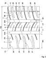
FIG. 1 is a development of a tread portion of a tire according to an embodiment of the present invention; -
FIG. 2 is an enlarged view of an outer shoulder land portion inFIG. 1 ; -
FIG. 3 is a cross-sectional view taken along a line A-A inFIG. 2 ; -
FIG. 4(A) is a cross-sectional view taken along a line B-B inFIG. 2 ; -
FIG. 4(B) is a cross-sectional view taken along a line C-C inFIG. 2 ; -
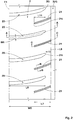
FIG. 5 is an enlarged view of a crown land portion inFIG. 1 ; -
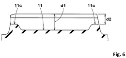
FIG. 6 is a cross-sectional view taken along a line D-D inFIG. 5 ; -
FIG. 7(A) is a cross-sectional view taken along a line E-E inFIG. 5 ; -
FIG. 7(B) is a cross-sectional view taken along a line F-F inFIG. 5 ; -
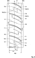
FIG. 8 is an enlarged view of an inner shoulder land portion inFIG. 1 ; -
FIG. 9 is a cross-sectional view taken along a line G-G inFIG. 8 ; and -
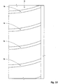
FIG. 10 is an enlarged view of an outer shoulder land portion of a comparative example. - Hereinafter, an embodiment of the present invention will be described with reference to the drawings.
-
FIG. 1 shows a development of atread portion 2 of a tire 1 according to the present embodiment. The tire 1 according to the present embodiment is formed, for example, as a pneumatic tire for a passenger car. However, the present invention is not limited to such an example. - As shown in
FIG. 1 , for the tire 1 according to the present embodiment, how the tire 1 is to be oriented when mounted to a vehicle is specified. How the tire 1 is to be oriented when mounted to a vehicle is indicated on a sidewall portion (not shown) of the tire 1, for example, by characters or a pictogram. When the tire 1 is mounted to a vehicle, the right side inFIG. 1 corresponds to the inner side of the vehicle, and the left side inFIG. 1 corresponds to the outer side of the vehicle. - Since how the tire 1 is to be oriented when mounted to a vehicle is specified, an outer tread edge T1 located at the outer side of the vehicle when the tire 1 is mounted on a vehicle and an inner tread edge T2 located at the inner side of the vehicle when the tire 1 is mounted on the vehicle are defined in the
tread portion 2. Accordingly, thetread portion 2 includes: anouter tread portion 2A located between a tire equator C and the outer tread edge T1; and aninner tread portion 2B located between the tire equator C and the inner tread edge T2. - In the case of a pneumatic tire, each of the outer tread edge T1 and the inner tread edge T2 is a ground contact position at the outermost side in the tire axial direction when a normal load is applied to the tire 1 in a normal state and the tire 1 is brought into contact with a plane at a camber angle of 0°. The normal state is a state where the tire is mounted to a normal rim and inflated to a normal internal pressure and no load is applied to the tire. In the present specification, unless otherwise specified, dimensions of components of the tire and the like are values measured in the normal state.
- The "normal rim" is a rim that is defined, in a standard system including a standard on which the tire is based, by the standard for each tire, and is, for example, the "standard rim" in the JATMA standard, the "Design Rim" in the TRA standard, or the "Measuring Rim" in the ETRTO standard.
- The "normal internal pressure" is an air pressure that is defined, in a standard system including a standard on which the tire is based, by the standard for each tire, and is the "maximum air pressure" in the JATMA standard, the maximum value indicated in the table "TIRE LOAD LIMITS AT VARIOUS COLD INFLATION PRESSURES" in the TRA standard, or the "INFLATION PRESSURE" in the ETRTO standard.
- The "normal load" is a load that is defined, in a standard system including a standard on which the tire is based, by the standard for each tire, and is the "maximum load capacity" in the JATMA standard, the maximum value indicated in the table "TIRE LOAD LIMITS AT VARIOUS COLD INFLATION PRESSURES" in the TRA standard, or the "LOAD CAPACITY" in the ETRTO standard.
- The
tread portion 2 includesmain grooves 3 that continuously extend in the tire circumferential direction. Eachmain groove 3 extends continuously in the tire circumferential direction so as to have relatively large width and depth such that water on a road surface is drained rearward of the tire. In a preferred embodiment, eachmain groove 3 has a groove width and depth of 5 mm or greater and more preferably 6 mm or greater. In addition, the groove width W1 of themain groove 3 is, for example, 5.0% to 9.0% of a tread width TW. The depth of themain groove 3 is, for example, 5 to 12 mm. The tread width TW is the distance in the tire axial direction from the outer tread edge T1 to the inner tread edge T2 in the normal state. In the present embodiment, each main groove extends straight along the tire circumferential direction. In another embodiment, each main groove may extend non-linearly such as in a zigzag manner or in a wavy manner. - The
main grooves 3 include a first crownmain groove 4 and a second crownmain groove 5 that are provided such that the tire equator C is located therebetween. The first crownmain groove 4 is provided between the tire equator C and the outer tread edge T1. The second crownmain groove 5 is provided between the tire equator C and the inner tread edge T2. - The distance L1 in the tire axial direction from the tire equator C to the groove center line of the first crown
main groove 4 and the distance L2 in the tire axial direction from the tire equator C to the groove center line of the second crownmain groove 5 are, for example, preferably 0.08 to 0.20 times the tread width TW. In addition, in the present embodiment, the distance L1 is smaller than the distance L2. - Due to the presence of the
main grooves 3, thetread portion 2 has acrown land portion 6, an outershoulder land portion 7, and an innershoulder land portion 8. Thecrown land portion 6 is demarcated between the first crownmain groove 4 and the second crownmain groove 5. The outershoulder land portion 7 is demarcated between the first crownmain groove 4 and the outer tread edge T1. The innershoulder land portion 8 is demarcated between the second crownmain groove 5 and the inner tread edge T2. - The outer
shoulder land portion 7 has the largest width in the tire axial direction among the three land portions. Such an outershoulder land portion 7 has high stiffness, and allows steering stability to be improved while good uneven wear resistance is exhibited. The width W5 in the tire axial direction of the outershoulder land portion 7 is preferably, for example, 0.30 to 0.45 times the tread width TW. -
FIG. 2 shows an enlarged view of the outershoulder land portion 7. As shown inFIG. 2 , the outershoulder land portion 7 has outershoulder lateral grooves 20 andouter shoulder sipes 21. Each outer shoulderlateral groove 20 extends from the outer tread edge T1 and terminates within the outershoulder land portion 7. Eachouter shoulder sipe 21 extends from the first crownmain groove 4 and terminates within the outershoulder land portion 7. In the present specification, the term "sipe" is defined as a narrow cut having a body portion with a width less than 2.0 mm. The width of the main portion of the sipe is preferably less than 1.5 mm and more preferably 0.4 to 1.0 mm. The opening width of the sipe on a road surface may be, for example, 1.5 to 2.5 mm. - The outer
shoulder lateral grooves 20 are easily opened at the outer tread edge T1 side and are unlikely to be opened at the terminal end side within the outershoulder land portion 7. In addition, theouter shoulder sipes 21 are easily opened at the first crownmain groove 4 side and are unlikely to be opened at the terminal end side within the outershoulder land portion 7. Thus, the outershoulder land portion 7, which has the outershoulder lateral grooves 20 and theouter shoulder sipes 21, easily causes torsional deformation in a ground-contact surface thereof when a slip angle is given. Therefore, in the tire 1 according to the present invention, when a slip angle is given, the ground-contact surface of the outershoulder land portion 7 immediately causes torsional deformation so as to follow a road surface, and further generates cornering force without delay. In particular, since the outershoulder land portion 7 has the largest width in the tire axial direction among the three land portions, the outershoulder land portion 7 can be expected to generate greater cornering force. Thus, the tire 1 according to the present invention has high initial responsiveness at the time of turning and exhibits good steering stability. - Each of the outer
shoulder lateral grooves 20 and theouter shoulder sipes 21 has a terminal end within the outershoulder land portion 7. In the present embodiment, the terminal ends 21i of theouter shoulder sipes 21 are located outward of the terminal ends 20i of the outershoulder lateral grooves 20 in the tire axial direction. Accordingly, torsional deformation easily occurs in the outershoulder land portion 7, and initial responsiveness can be further increased. - The distance L11 in the tire axial direction from the
terminal end 20i of the outer shoulderlateral groove 20 to theterminal end 21i of theouter shoulder sipe 21 is, for example, 0.20 to 0.35 times the width W5 in the tire axial direction of the outershoulder land portion 7. Accordingly, good initial responsiveness is exhibited while desired ride comfort is maintained. - Each outer shoulder
lateral groove 20 is, for example, smoothly curved. For example, the angle of the outer shoulderlateral groove 20 relative to the tire axial direction preferably gradually increases from the outer tread edge T1 toward the first crownmain groove 4 side. The angle of the outer shoulderlateral groove 20 relative to the tire axial direction is preferably, for example, 0 to 20°. - The length L6 in the tire axial direction of the outer shoulder
lateral groove 20 is preferably, for example, 0.70 to 0.92 times the width W5 in the tire axial direction of the outershoulder land portion 7. In addition, the groove width W6 of the outer shoulderlateral groove 20 is preferably 0.25 to 0.45 times the groove width W1 of themain groove 3. -
FIG. 3 shows a cross-sectional view of the outer shoulderlateral groove 20 taken along a line A-A inFIG. 2 . As shown inFIG. 3 , the outer shoulderlateral groove 20 includes aninner portion 23 at the first crownmain groove 4 side with respect to theterminal end 21i of the outer shoulder sipe 21 (shown inFIG. 2 ). For example, the depth of theinner portion 23 preferably gradually decreases toward the inner side in the tire axial direction. The outer shoulderlateral groove 20 having such aninner portion 23 allows ride comfort and steering stability to be improved in a balanced manner. - As shown in
FIG. 2 , eachouter shoulder sipe 21 is, for example, curved so as to be convex in the same direction as the outer shoulderlateral groove 20. The angle of theouter shoulder sipe 21 relative to the tire axial direction is preferably within the same range as for the outershoulder lateral grooves 20. The radius of curvature of theouter shoulder sipe 21 is preferably, for example, 100 to 150 mm. - The length L7 in the tire axial direction of the
outer shoulder sipe 21 is preferably, for example, 0.30 to 0.70 times the width W5 in the tire axial direction of the outershoulder land portion 7. -
FIG. 4(A) shows a cross-sectional view of theouter shoulder sipe 21 taken along a line B-B inFIG. 2 .FIG. 4(A) shows a transverse cross-section orthogonal to the longitudinal direction of theouter shoulder sipe 21. As shown inFIG. 4(A) , theouter shoulder sipe 21 includes abody portion 21a and awide portion 21b that is disposed outward of thebody portion 21a in the tire radial direction and that has a larger width than thebody portion 21a. The width W3 of thebody portion 21a is preferably, for example, 0.4 to 0.8 mm. The width W4 of thewide portion 21b is preferably, for example, 1.0 to 2.0 mm. The width W4 of thewide portion 21b is more preferably 1.5 to 4.0 times the width W3 of thebody portion 21a. Such anouter shoulder sipe 21 sufficiently reduces the stiffness of the outershoulder land portion 7 and allows good ride comfort to be exhibited. -
FIG. 4(B) shows a cross-sectional view of theouter shoulder sipe 21 taken along a line C-C inFIG. 2 . As shown inFIG. 4(B) , theouter shoulder sipe 21 has ashallow portion 21c having a depth smaller than the maximum depth of theouter shoulder sipe 21. In the present embodiment, for example, theouter shoulder sipe 21 has ashallow portion 21c at an end portion thereof at the inner side in the tire axial direction. Theshallow portion 21c serves to inhibit the sipe from being excessively opened and improve steering stability. - The depth d8 of the
shallow portion 21c is preferably 0.15 to 0.50 times the depth of themain groove 3. In addition, the depth d8 of theshallow portion 21c is, for example, 0.60 to 0.75 times the maximum depth d7 of theouter shoulder sipe 21. - The length L9 in the tire axial direction of the
shallow portion 21c is preferably, for example, larger than the distance L8 (shown inFIG. 2 ) in the tire axial direction from a groove edge of the first crownmain groove 4 to theterminal end 20i of the outer shoulderlateral groove 20. Such ashallow portion 21c can sufficiently inhibit theouter shoulder sipe 21 from being opened and allows steering stability and uneven wear resistance to be improved. -
FIG. 5 shows an enlarged view of thecrown land portion 6. As shown inFIG. 5 , the width W2 of thecrown land portion 6 is preferably, for example, 0.15 to 0.25 times the tread width TW (shown inFIG. 1 , and the same applies below). In addition, the center in the tire axial direction of thecrown land portion 6 is located at the second crownmain groove 5 side with respect to the tire equator C. Accordingly, in the present embodiment, the width of thecrown land portion 6 included in theinner tread portion 2B is increased, and good steering stability is exhibited. - A displacement amount Lc by which the center of the
crown land portion 6 is displaced is preferably, for example, 0.05 to 0.10 times the width W2 in the tire axial direction of thecrown land portion 6. The displacement amount Lc is the distance in the tire axial direction from the tire equator C to thecenter 6c in the tire axial direction of thecrown land portion 6. - The
crown land portion 6 has a plurality ofcrown sipes 10. The crown sipes 10 includefirst crown sipes 11,second crown sipes 12, andthird crown sipes 13. Eachfirst crown sipe 11 connects the first crownmain groove 4 to the second crownmain groove 5. Eachsecond crown sipe 12 extends from the first crownmain groove 4 and terminates within thecrown land portion 6. Eachthird crown sipe 13 extends from the second crownmain groove 5 and terminates within thecrown land portion 6. - Each of
such crown sipes 10 appropriately reduces the stiffness of thecrown land portion 6 and allows ride comfort to be improved while desired steering stability is maintained. In addition, eachcrown sipe 10 also serves to make the stiffness distribution of thecrown land portion 6 uniform and inhibit uneven wear of thecrown land portion 6. - The
second crown sipes 12 and thethird crown sipes 13, which terminate within thecrown land portion 6, make torsional deformation easily occur in the ground-contact surface of thecrown land portion 6 and allow further increase in initial responsiveness at the time of turning. - Each
first crown sipe 11 is preferably, for example, curved so as to be convex at one side in the tire circumferential direction. The radius of curvature of thefirst crown sipe 11 is, for example, 45 to 65 mm. The radius of curvature of thefirst crown sipe 11 is preferably, for example, smaller than the radius of curvature of theouter shoulder sipe 21. In addition, in the present embodiment, the angle of thefirst crown sipe 11 relative to the tire axial direction gradually increases from the first crownmain groove 4 side toward the second crownmain groove 5. The angle of thefirst crown sipe 11 relative to the tire axial direction is preferably, for example, 5 to 30°. Such afirst crown sipe 11 can provide frictional force in multiple directions by the edges thereof. - The
first crown sipe 11 preferably has the same cross-sectional shape as theouter shoulder sipe 21, in a transverse cross-section orthogonal to the longitudinal direction of thefirst crown sipe 11. That is, thefirst crown sipe 11 includes a body portion and a wide portion that is disposed outward of the body portion in the tire radial direction and that has a larger width than the body portion (not shown). Such afirst crown sipe 11 serves to improve ride comfort. -
FIG. 6 shows a cross-sectional view of thefirst crown sipe 11 taken along a line D-D inFIG. 5 . As shown inFIG. 6 , thefirst crown sipe 11 has ashallow portion 11c having a depth smaller than the maximum depth of thefirst crown sipe 11. In the present embodiment, thefirst crown sipe 11 has, for example,shallow portions 11c at both end portions thereof in the tire axial direction. Such afirst crown sipe 11 can prevent thecrown land portion 6 from being excessively opened when contact pressure is applied to thecrown land portion 6, and allows good steering stability and uneven wear resistance to be exhibited. - The maximum depth d1 of the
first crown sipe 11 is, for example, 0.60 to 1.00 times the depth of themain groove 3. The depth d2 of theshallow portion 11c of thefirst crown sipe 11 is, for example, 0.40 to 0.85 times the maximum depth d1. - As shown in
FIG. 5 , eachsecond crown sipe 12 and eachthird crown sipe 13 are provided between twofirst crown sipes 11 adjacent to each other in the tire circumferential direction. The length L3 in the tire axial direction of thesecond crown sipe 12 and the length L4 in the tire axial direction of thethird crown sipe 13 are, for example, 0.50 to 0.80 times the width W2 of thecrown land portion 6. - Each of the
second crown sipes 12 and thethird crown sipes 13 has an inner end at which the crown sipe terminates within thecrown land portion 6. In the present embodiment, the inner ends 13i of thethird crown sipes 13 are located at the first crownmain groove 4 side with respect to the inner ends 12i of thesecond crown sipes 12. A sipe overlapping length L5 that is the distance in the tire axial direction from theinner end 12i of thesecond crown sipe 12 to theinner end 13i of thethird crown sipe 13 is preferably, for example, not less than 0.25 times and more preferably not less than 0.30 times, and is preferably not greater than 0.45 times and more preferably not greater than 0.40 times the width W2 of thecrown land portion 6. Such arrangement of thesecond crown sipes 12 and thethird crown sipes 13 serves to make torsional deformation of thecrown land portion 6 easily occur and increase initial responsiveness. - Each of the
second crown sipes 12 and thethird crown sipes 13 is curved so as to be convex in the same direction as thefirst crown sipe 11. Accordingly, the angle of each of thesecond crown sipes 12 and thethird crown sipes 13 relative to the tire axial direction gradually increases from the first crownmain groove 4 side toward the second crownmain groove 5 side. The angles of thesecond crown sipes 12 and thethird crown sipes 13 relative to the tire axial direction and the radii of curvature of thesecond crown sipes 12 and thethird crown sipes 13 are preferably within the same ranges as for thefirst crown sipes 11. - Each of the
second crown sipes 12 and thethird crown sipes 13 preferably, for example, extends from a tread surface of the land portion to a bottom portion so as to have a width of 0.4 to 0.8 mm. Accordingly, on the outer surface of thetread portion 2, the opening width of thefirst crown sipe 11 is larger than the opening width of thesecond crown sipe 12 and the opening width of thethird crown sipe 13. Accordingly, the uneven wear resistance around thesecond crown sipe 12 and thethird crown sipe 13 is improved. -
FIG. 7(A) shows a cross-sectional view of thesecond crown sipe 12 taken along a line E-E inFIG. 5 , andFIG. 7(B) shows a cross-sectional view of thethird crown sipe 13 taken along a line F-F inFIG. 5 . As shown inFIGS. 7(A) and 7(B) , the maximum depth d3 of thesecond crown sipe 12 and the maximum depth d5 of thethird crown sipe 13 are each preferably smaller than the maximum depth d1 of thefirst crown sipe 11 and specifically 0.40 to 0.90 times the depth d1. Such asecond crown sipe 12 and such athird crown sipe 13 serve to inhibit excessive decrease of the stiffness of thecrown land portion 6 and improve steering stability. - The maximum depth d3 of the
second crown sipe 12 is preferably larger than the maximum depth d5 of thethird crown sipe 13. - In order to further increase initial responsiveness, the maximum depth d5 of the
third crown sipe 13 is preferably larger than the depth d2 of theshallow portion 11c of thefirst crown sipe 11. - Each
second crown sipe 12 preferably has ashallow portion 12c having a depth smaller than the maximum depth of thesecond crown sipe 12. Similarly, eachthird crown sipe 13 preferably has ashallow portion 13c having a depth smaller than the maximum depth of thethird crown sipe 13. In the present embodiment, eachshallow portion main groove 3 side. Such ashallow portion - The depth d4 of the
shallow portion 12c of thesecond crown sipe 12 and the depth d6 of theshallow portion 13c of thethird crown sipe 13 are, for example, 0.15 to 0.30 times the depth of themain groove 3. In a preferred embodiment, the depth d4 of theshallow portion 12c of thesecond crown sipe 12 and the depth d6 of theshallow portion 13c of thethird crown sipe 13 are each smaller than the depth d2 of theshallow portion 11c of thefirst crown sipe 11. Accordingly, the stiffness around thesecond crown sipe 12 and thethird crown sipe 13 is improved, and the uneven wear resistance improves. -
FIG. 8 shows an enlarged view of the innershoulder land portion 8. As shown inFIG. 8 , the width W7 in the tire axial direction of the innershoulder land portion 8 is preferably, for example, 0.25 to 0.35 times the tread width TW. - The inner
shoulder land portion 8 has a longitudinalnarrow groove 25. The longitudinalnarrow groove 25 has a groove width and a groove depth that are less than 5 mm, and is distinguished from the abovemain groove 3. In the present embodiment, the groove width W8 of the longitudinalnarrow groove 25 is, for example, 0.20 to 0.30 times the groove width W1 of themain groove 3. The innershoulder land portion 8 includes: afirst portion 26 demarcated between the second crownmain groove 5 and the longitudinalnarrow groove 25; and asecond portion 27 demarcated between the longitudinalnarrow groove 25 and the inner tread edge T2. - The width W9 in the tire axial direction of the
first portion 26 is preferably, for example, 0.55 to 0.65 times the width W7 of the innershoulder land portion 8. The width W10 in the tire axial direction of thesecond portion 27 is preferably, for example, 0.30 to 0.40 times the width W7 of the innershoulder land portion 8. - The inner
shoulder land portion 8 has inner shoulderlateral grooves 28 andinner shoulder sipes 29. Each inner shoulderlateral groove 28 extends from the inner tread edge T2 and terminates within the innershoulder land portion 8. Eachinner shoulder sipe 29 extends from the second crownmain groove 5 to the inner tread edge T2. - The inner shoulder
lateral groove 28, for example, crosses the longitudinalnarrow groove 25 and terminates within thefirst portion 26 of the innershoulder land portion 8. The length L10 in the tire axial direction of the inner shoulderlateral groove 28 is preferably, for example, 0.80 to 0.90 times the width W7 in the tire axial direction of the innershoulder land portion 8. - The depth of the inner shoulder
lateral groove 28 preferably, for example, gradually decreases toward the inner side in the tire axial direction, between the longitudinalnarrow groove 25 and the second crownmain groove 5. Such an inner shoulderlateral groove 28 serves to improve ride comfort and steering stability in a balanced manner. - The
inner shoulder sipe 29 is, for example, curved so as to be convex at one side in the tire circumferential direction. The radius of curvature of theinner shoulder sipe 29 is preferably, for example, larger than the radius of curvature of thefirst crown sipe 11. Specifically, the radius of curvature of theinner shoulder sipe 29 is 120 to 150 mm. - The
inner shoulder sipe 29 preferably has the same cross-sectional shape as thefirst crown sipe 11, in a transverse cross-section orthogonal to the longitudinal direction of theinner shoulder sipe 29. That is, theinner shoulder sipe 29 includes a body portion and a wide portion that is disposed outward of the body portion in the tire radial direction and that has a larger width than the body portion (not shown). Such aninner shoulder sipe 29 serves to improve ride comfort. -
FIG. 9 shows a cross-sectional view of theinner shoulder sipe 29 taken along a line G-G inFIG. 8 . As shown inFIG. 9 , theinner shoulder sipe 29 has ashallow portion 29c having a depth smaller than the maximum depth of theinner shoulder sipe 29. In the present embodiment, theinner shoulder sipe 29 has, for example, ashallow portion 29c at an end portion thereof at the inner side in the tire axial direction. Theshallow portion 29c serves to inhibit theinner shoulder sipe 29 from being excessively opened and improve steering stability and uneven wear resistance. - In the present embodiment, the width in the tire axial direction of the
shallow portion 29c provided in theinner shoulder sipe 29 is larger than the width in the tire axial direction of the shallow portion of eachcrown sipe 10. Such aninner shoulder sipe 29 serves to inhibit uneven wear of the innershoulder land portion 8. - As shown in
FIG. 1 , a land ratio of theouter tread portion 2A is preferably greater than a land ratio of theinner tread portion 2B. Accordingly, theouter tread portion 2A exerts great cornering force and allows good steering stability to be exhibited. In the present specification, the term "land ratio" is a ratio Sb/Sa of an actual total contact area Sb to a whole area Sa of a virtual ground-contact surface obtained by filling each groove and each sipe. - Although the tire according to the embodiment of the present invention has been described in detail above, the present invention is not limited to the above specific embodiments, and various modifications can be made to implement the present invention.
- Pneumatic tires with a size of 195/65R15 having the basic tread pattern in
FIG. 1 were produced as test tires on the basis of specifications in Table 1. As a comparative example, a tire including an outer shoulder land portion a provided with lateral grooves b extending from an outer tread edge to an outer crown main groove as shown inFIG. 10 was produced as a test tire. The pattern of the tire of the comparative example is the same as shown inFIG. 1 , except for the above structure. Each test tire was tested for steering stability and uneven wear resistance. The common specifications and the test methods for all the test tires are as follows. - Rim: 15×6.0
- Tire internal pressure: 200 kPa
- Test vehicle: a front-wheel-drive car having an engine displacement of 2000 cc
- Tire mounted position: all wheels
- Sensory evaluation was made by a driver for steering stability (including initial responsiveness at the time of turning) when the test vehicle ran on a paved road in a dry state. The results are indicated as scores with the score of the comparative example being 100. The greater the value is, the better the steering stability is.
- The wear energy of each outer shoulder land portion was measured using a wear energy measuring device. The results are indicated as indexes with the wear energy of the comparative example being 100. The smaller the value is, the lower the wear energy is and the better the uneven wear resistance is.
- The results of the tests are shown in Table 1.
[Table 1] Comparative Example Example 1 Example 2 Example 3 Example 4 Example 5 Example 6 Example 7 Example 8 Example 9 Drawing showing outer shoulder land portion FIG. 10 FIG. 2 FIG. 2 FIG. 2 FIG. 2 FIG. 2 FIG. 2 FIG. 2 FIG. 2 FIG. 2 Length L6 of outer shoulder lateral groove /width W5 of outer shoulder land portion 1.00 0.88 0.70 0.80 0.92 0.96 0.88 0.88 0.88 0.88 Length L7 of outer shoulder sipe /width W5 of outer shoulder land portion - 0.40 0.40 0.40 0.40 0.40 0.30 0.50 0.60 0.70 Steering stability (score) 100 106 104 106 105 104 105 106 107 107 Uneven wear resistance (index) 100 97 97 97 98 99 97 97 98 99 - As a result of the tests, it can be confirmed that the tires of the examples exhibit good steering stability. In addition, it can be confirmed that the tires of the examples also have improved uneven wear resistance.
Claims (7)
- A tire (1) for which how the tire (1) is to be oriented when mounted to a vehicle is specified, the tire (1) comprising a tread portion (2), wherein
the tread portion (2) hasan outer tread edge (T1) located at an outer side of the vehicle when the tire (1) is mounted on the vehicle,an inner tread edge (T2) located at an inner side of the vehicle when the tire (1) is mounted on the vehicle,a first crown main groove (4) extending continuously in a tire circumferential direction between the outer tread edge (T1) and a tire equator (C),a second crown main groove (5) extending continuously in the tire circumferential direction at the inner tread edge (T2) side with respect to the first crown main groove (4), andthree land portions (6, 7, 8) demarcated by the first crown main groove (4) and the second crown main groove (5),the land portions (6, 7, 8) include an outer shoulder land portion (7) demarcated between the outer tread edge (T1) and the first crown main groove (4),
the outer shoulder land portion (7) has a largest width (W5) in a tire axial direction among the three land portions (6, 7, 8), and
the outer shoulder land portion (7) has an outer shoulder lateral groove (20) that extends from the outer tread edge (T1) and that terminates within the outer shoulder land portion (7), and an outer shoulder sipe (21) that extends from the first crown main groove (4) and that terminates within the outer shoulder land portion (7). - The tire (1) according to claim 1, wherein
each of the outer shoulder lateral groove (20) and the outer shoulder sipe (21) has a terminal end (20i, 21i) within the outer shoulder land portion (7), and
the terminal end (21i) of the outer shoulder sipe (21) is located outward of the terminal end (20i) of the outer shoulder lateral groove (20) in the tire axial direction. - The tire (1) according to claim 2, wherein
the outer shoulder lateral groove (20) includes an inner portion (23) at the first crown main groove (4) side with respect to the terminal end (21i) of the outer shoulder sipe (21), and
a depth of the inner portion (23) gradually decreases toward an inner side in the tire axial direction. - The tire (1) according to any one of claims 1 to 3, wherein the outer shoulder sipe (21) has a shallow portion (21c) having a depth (d8) smaller than a maximum depth (d7) of the outer shoulder sipe (21).
- The tire (1) according to claim 4, wherein
the outer shoulder lateral groove (20) has a terminal end (20i) within the outer shoulder land portion (7), and
a length L9 in the tire axial direction of the shallow portion (21c) of the outer shoulder sipe (21) is larger than a distance (L8) in the tire axial direction from a groove edge of the first crown main groove (4) to the terminal end (20i) of the outer shoulder lateral groove (20). - The tire (1) according to any one of claims 1 to 5, wherein the outer shoulder sipe (21) includes a body portion (21a) and a wide portion (21b) that is disposed outward of the body portion (21a) in a tire radial direction and that has a larger width (W4) than the body portion (21a), in a transverse cross-section orthogonal to a longitudinal direction of the outer shoulder sipe (21).
- The tire (1) according to any one of claims 1 to 6, wherein
the tread portion (2) includes an outer tread portion (2A) located between the tire equator (C) and the outer tread edge (T1) and an inner tread portion (2B) located between the tire equator (C) and the inner tread edge (T2), and
a land ratio of the outer tread portion (2A) is greater than a land ratio of the inner tread portion (2B).
Applications Claiming Priority (1)
| Application Number | Priority Date | Filing Date | Title |
|---|---|---|---|
| JP2018132543A JP7070180B2 (en) | 2018-07-12 | 2018-07-12 | tire |
Publications (2)
| Publication Number | Publication Date |
|---|---|
| EP3594022A1 true EP3594022A1 (en) | 2020-01-15 |
| EP3594022B1 EP3594022B1 (en) | 2020-12-23 |
Family
ID=67226050
Family Applications (1)
| Application Number | Title | Priority Date | Filing Date |
|---|---|---|---|
| EP19185308.4A Active EP3594022B1 (en) | 2018-07-12 | 2019-07-09 | Tire |
Country Status (4)
| Country | Link |
|---|---|
| US (1) | US11772430B2 (en) |
| EP (1) | EP3594022B1 (en) |
| JP (1) | JP7070180B2 (en) |
| CN (1) | CN110712480B (en) |
Cited By (1)
| Publication number | Priority date | Publication date | Assignee | Title |
|---|---|---|---|---|
| EP3718787A1 (en) * | 2019-04-03 | 2020-10-07 | Sumitomo Rubber Industries, Ltd. | Tire |
Families Citing this family (1)
| Publication number | Priority date | Publication date | Assignee | Title |
|---|---|---|---|---|
| US20220242170A1 (en) * | 2019-07-01 | 2022-08-04 | The Yokohama Rubber Co., Ltd. | Pneumatic tire |
Citations (6)
| Publication number | Priority date | Publication date | Assignee | Title |
|---|---|---|---|---|
| JP2013139166A (en) * | 2011-12-28 | 2013-07-18 | Sumitomo Rubber Ind Ltd | Pneumatic tire |
| EP2664464A1 (en) * | 2012-05-15 | 2013-11-20 | Sumitomo Rubber Industries, Ltd. | Pneumatic tire |
| JP2015024797A (en) | 2013-07-29 | 2015-02-05 | 住友ゴム工業株式会社 | Pneumatic tire |
| EP3081393A1 (en) * | 2013-12-27 | 2016-10-19 | Sumitomo Rubber Industries, Ltd. | Pneumatic tire |
| EP3213931A1 (en) * | 2016-03-04 | 2017-09-06 | Sumitomo Rubber Industries, Ltd. | Pneumatic tire |
| EP3549794A1 (en) * | 2018-04-06 | 2019-10-09 | Sumitomo Rubber Industries Limited | Tyre |
Family Cites Families (26)
| Publication number | Priority date | Publication date | Assignee | Title |
|---|---|---|---|---|
| JPH01314609A (en) * | 1988-06-15 | 1989-12-19 | Yokohama Rubber Co Ltd:The | Pneumatic tire |
| EP1021306B1 (en) * | 1997-10-03 | 2002-03-20 | The Goodyear Tire & Rubber Company | Tread for a pneumatic tire |
| US6439284B1 (en) * | 1997-10-03 | 2002-08-27 | The Goodyear Tire & Rubber Company | Tread for a pneumatic tire including aquachannel |
| JP2002225511A (en) | 2001-01-31 | 2002-08-14 | Yokohama Rubber Co Ltd:The | Tread pattern of pneumatic tire for automobile |
| CN1310777C (en) * | 2001-12-26 | 2007-04-18 | 株式会社普利司通 | Pneumatic radial tire |
| JP4348321B2 (en) * | 2005-06-30 | 2009-10-21 | 住友ゴム工業株式会社 | Pneumatic tire |
| JP4217267B1 (en) * | 2007-09-13 | 2009-01-28 | 住友ゴム工業株式会社 | Pneumatic tire |
| JP2011143795A (en) | 2010-01-13 | 2011-07-28 | Bridgestone Corp | Pneumatic tire |
| JP5395786B2 (en) | 2010-12-29 | 2014-01-22 | 住友ゴム工業株式会社 | Pneumatic tire |
| JP5146564B2 (en) | 2011-05-10 | 2013-02-20 | 横浜ゴム株式会社 | Pneumatic tire |
| JP5480875B2 (en) * | 2011-11-25 | 2014-04-23 | 住友ゴム工業株式会社 | Pneumatic tire |
| JP5629283B2 (en) * | 2012-03-15 | 2014-11-19 | 住友ゴム工業株式会社 | Pneumatic tire |
| JP5658728B2 (en) * | 2012-11-20 | 2015-01-28 | 住友ゴム工業株式会社 | Pneumatic tire |
| JP5957405B2 (en) | 2013-03-19 | 2016-07-27 | 住友ゴム工業株式会社 | Pneumatic tire |
| JP6231974B2 (en) * | 2014-11-27 | 2017-11-15 | 住友ゴム工業株式会社 | Pneumatic tire |
| JP6417226B2 (en) * | 2015-01-26 | 2018-10-31 | 住友ゴム工業株式会社 | Pneumatic tire |
| JP6374819B2 (en) * | 2015-03-27 | 2018-08-15 | 住友ゴム工業株式会社 | Pneumatic tire |
| JP6467309B2 (en) * | 2015-07-16 | 2019-02-13 | 住友ゴム工業株式会社 | Pneumatic tire |
| JP6786794B2 (en) * | 2015-12-10 | 2020-11-18 | 住友ゴム工業株式会社 | Pneumatic tires |
| JP6784066B2 (en) * | 2016-06-08 | 2020-11-11 | 住友ゴム工業株式会社 | Pneumatic tires |
| JP6711169B2 (en) * | 2016-06-24 | 2020-06-17 | 住友ゴム工業株式会社 | tire |
| JP6790496B2 (en) * | 2016-06-24 | 2020-11-25 | 住友ゴム工業株式会社 | Pneumatic tires |
| JP6750358B2 (en) * | 2016-07-11 | 2020-09-02 | 住友ゴム工業株式会社 | Pneumatic tire |
| JP6790663B2 (en) | 2016-09-26 | 2020-11-25 | 住友ゴム工業株式会社 | tire |
| JP6674414B2 (en) * | 2017-07-04 | 2020-04-01 | 住友ゴム工業株式会社 | Pneumatic tire |
| JP7091897B2 (en) * | 2018-07-12 | 2022-06-28 | 住友ゴム工業株式会社 | tire |
-
2018
- 2018-07-12 JP JP2018132543A patent/JP7070180B2/en active Active
-
2019
- 2019-07-01 CN CN201910584776.5A patent/CN110712480B/en active Active
- 2019-07-09 EP EP19185308.4A patent/EP3594022B1/en active Active
- 2019-07-11 US US16/508,664 patent/US11772430B2/en active Active
Patent Citations (6)
| Publication number | Priority date | Publication date | Assignee | Title |
|---|---|---|---|---|
| JP2013139166A (en) * | 2011-12-28 | 2013-07-18 | Sumitomo Rubber Ind Ltd | Pneumatic tire |
| EP2664464A1 (en) * | 2012-05-15 | 2013-11-20 | Sumitomo Rubber Industries, Ltd. | Pneumatic tire |
| JP2015024797A (en) | 2013-07-29 | 2015-02-05 | 住友ゴム工業株式会社 | Pneumatic tire |
| EP3081393A1 (en) * | 2013-12-27 | 2016-10-19 | Sumitomo Rubber Industries, Ltd. | Pneumatic tire |
| EP3213931A1 (en) * | 2016-03-04 | 2017-09-06 | Sumitomo Rubber Industries, Ltd. | Pneumatic tire |
| EP3549794A1 (en) * | 2018-04-06 | 2019-10-09 | Sumitomo Rubber Industries Limited | Tyre |
Cited By (1)
| Publication number | Priority date | Publication date | Assignee | Title |
|---|---|---|---|---|
| EP3718787A1 (en) * | 2019-04-03 | 2020-10-07 | Sumitomo Rubber Industries, Ltd. | Tire |
Also Published As
| Publication number | Publication date |
|---|---|
| JP7070180B2 (en) | 2022-05-18 |
| US11772430B2 (en) | 2023-10-03 |
| CN110712480A (en) | 2020-01-21 |
| CN110712480B (en) | 2023-06-20 |
| JP2020006925A (en) | 2020-01-16 |
| EP3594022B1 (en) | 2020-12-23 |
| US20200016937A1 (en) | 2020-01-16 |
Similar Documents
| Publication | Publication Date | Title |
|---|---|---|
| EP3296127B1 (en) | Pneumatic tire | |
| EP3260308B1 (en) | Tire | |
| EP2664464B1 (en) | Pneumatic tire | |
| EP3539798B1 (en) | Tyre | |
| EP3388255B1 (en) | Pneumatic tire | |
| EP3318421B1 (en) | Tire | |
| EP3564047B1 (en) | Tyre | |
| EP3689642B1 (en) | Tire | |
| EP3572243B1 (en) | Tire | |
| US20220001698A1 (en) | Tyre | |
| EP3530488B1 (en) | Tyre for winter | |
| EP3489038A1 (en) | Tyre | |
| EP3594022B1 (en) | Tire | |
| EP3647077A1 (en) | Tire | |
| EP3594021B1 (en) | Tyre | |
| JP7103001B2 (en) | tire | |
| EP4201709A1 (en) | Tire | |
| EP4105041B1 (en) | Tire | |
| EP3835087B1 (en) | Tire | |
| EP3747672B1 (en) | Tire tread | |
| EP4105040B1 (en) | Tire | |
| EP4070970B1 (en) | Tire | |
| EP3785939B1 (en) | Tyre |
Legal Events
| Date | Code | Title | Description |
|---|---|---|---|
| PUAI | Public reference made under article 153(3) epc to a published international application that has entered the european phase |
Free format text: ORIGINAL CODE: 0009012 |
|
| STAA | Information on the status of an ep patent application or granted ep patent |
Free format text: STATUS: THE APPLICATION HAS BEEN PUBLISHED |
|
| AK | Designated contracting states |
Kind code of ref document: A1 Designated state(s): AL AT BE BG CH CY CZ DE DK EE ES FI FR GB GR HR HU IE IS IT LI LT LU LV MC MK MT NL NO PL PT RO RS SE SI SK SM TR |
|
| AX | Request for extension of the european patent |
Extension state: BA ME |
|
| STAA | Information on the status of an ep patent application or granted ep patent |
Free format text: STATUS: REQUEST FOR EXAMINATION WAS MADE |
|
| 17P | Request for examination filed |
Effective date: 20200319 |
|
| RBV | Designated contracting states (corrected) |
Designated state(s): AL AT BE BG CH CY CZ DE DK EE ES FI FR GB GR HR HU IE IS IT LI LT LU LV MC MK MT NL NO PL PT RO RS SE SI SK SM TR |
|
| STAA | Information on the status of an ep patent application or granted ep patent |
Free format text: STATUS: EXAMINATION IS IN PROGRESS |
|
| 17Q | First examination report despatched |
Effective date: 20200508 |
|
| GRAP | Despatch of communication of intention to grant a patent |
Free format text: ORIGINAL CODE: EPIDOSNIGR1 |
|
| STAA | Information on the status of an ep patent application or granted ep patent |
Free format text: STATUS: GRANT OF PATENT IS INTENDED |
|
| INTG | Intention to grant announced |
Effective date: 20201014 |
|
| GRAS | Grant fee paid |
Free format text: ORIGINAL CODE: EPIDOSNIGR3 |
|
| GRAA | (expected) grant |
Free format text: ORIGINAL CODE: 0009210 |
|
| STAA | Information on the status of an ep patent application or granted ep patent |
Free format text: STATUS: THE PATENT HAS BEEN GRANTED |
|
| AK | Designated contracting states |
Kind code of ref document: B1 Designated state(s): AL AT BE BG CH CY CZ DE DK EE ES FI FR GB GR HR HU IE IS IT LI LT LU LV MC MK MT NL NO PL PT RO RS SE SI SK SM TR |
|
| REG | Reference to a national code |
Ref country code: GB Ref legal event code: FG4D |
|
| REG | Reference to a national code |
Ref country code: DE Ref legal event code: R096 Ref document number: 602019001871 Country of ref document: DE |
|
| REG | Reference to a national code |
Ref country code: AT Ref legal event code: REF Ref document number: 1347372 Country of ref document: AT Kind code of ref document: T Effective date: 20210115 |
|
| REG | Reference to a national code |
Ref country code: IE Ref legal event code: FG4D |
|
| PG25 | Lapsed in a contracting state [announced via postgrant information from national office to epo] |
Ref country code: GR Free format text: LAPSE BECAUSE OF FAILURE TO SUBMIT A TRANSLATION OF THE DESCRIPTION OR TO PAY THE FEE WITHIN THE PRESCRIBED TIME-LIMIT Effective date: 20210324 Ref country code: NO Free format text: LAPSE BECAUSE OF FAILURE TO SUBMIT A TRANSLATION OF THE DESCRIPTION OR TO PAY THE FEE WITHIN THE PRESCRIBED TIME-LIMIT Effective date: 20210323 Ref country code: RS Free format text: LAPSE BECAUSE OF FAILURE TO SUBMIT A TRANSLATION OF THE DESCRIPTION OR TO PAY THE FEE WITHIN THE PRESCRIBED TIME-LIMIT Effective date: 20201223 Ref country code: FI Free format text: LAPSE BECAUSE OF FAILURE TO SUBMIT A TRANSLATION OF THE DESCRIPTION OR TO PAY THE FEE WITHIN THE PRESCRIBED TIME-LIMIT Effective date: 20201223 |
|
| REG | Reference to a national code |
Ref country code: AT Ref legal event code: MK05 Ref document number: 1347372 Country of ref document: AT Kind code of ref document: T Effective date: 20201223 |
|
| REG | Reference to a national code |
Ref country code: NL Ref legal event code: MP Effective date: 20201223 |
|
| PG25 | Lapsed in a contracting state [announced via postgrant information from national office to epo] |
Ref country code: LV Free format text: LAPSE BECAUSE OF FAILURE TO SUBMIT A TRANSLATION OF THE DESCRIPTION OR TO PAY THE FEE WITHIN THE PRESCRIBED TIME-LIMIT Effective date: 20201223 Ref country code: SE Free format text: LAPSE BECAUSE OF FAILURE TO SUBMIT A TRANSLATION OF THE DESCRIPTION OR TO PAY THE FEE WITHIN THE PRESCRIBED TIME-LIMIT Effective date: 20201223 Ref country code: BG Free format text: LAPSE BECAUSE OF FAILURE TO SUBMIT A TRANSLATION OF THE DESCRIPTION OR TO PAY THE FEE WITHIN THE PRESCRIBED TIME-LIMIT Effective date: 20210323 |
|
| PG25 | Lapsed in a contracting state [announced via postgrant information from national office to epo] |
Ref country code: NL Free format text: LAPSE BECAUSE OF FAILURE TO SUBMIT A TRANSLATION OF THE DESCRIPTION OR TO PAY THE FEE WITHIN THE PRESCRIBED TIME-LIMIT Effective date: 20201223 Ref country code: HR Free format text: LAPSE BECAUSE OF FAILURE TO SUBMIT A TRANSLATION OF THE DESCRIPTION OR TO PAY THE FEE WITHIN THE PRESCRIBED TIME-LIMIT Effective date: 20201223 |
|
| REG | Reference to a national code |
Ref country code: LT Ref legal event code: MG9D |
|
| PG25 | Lapsed in a contracting state [announced via postgrant information from national office to epo] |
Ref country code: LT Free format text: LAPSE BECAUSE OF FAILURE TO SUBMIT A TRANSLATION OF THE DESCRIPTION OR TO PAY THE FEE WITHIN THE PRESCRIBED TIME-LIMIT Effective date: 20201223 Ref country code: RO Free format text: LAPSE BECAUSE OF FAILURE TO SUBMIT A TRANSLATION OF THE DESCRIPTION OR TO PAY THE FEE WITHIN THE PRESCRIBED TIME-LIMIT Effective date: 20201223 Ref country code: PT Free format text: LAPSE BECAUSE OF FAILURE TO SUBMIT A TRANSLATION OF THE DESCRIPTION OR TO PAY THE FEE WITHIN THE PRESCRIBED TIME-LIMIT Effective date: 20210423 Ref country code: EE Free format text: LAPSE BECAUSE OF FAILURE TO SUBMIT A TRANSLATION OF THE DESCRIPTION OR TO PAY THE FEE WITHIN THE PRESCRIBED TIME-LIMIT Effective date: 20201223 Ref country code: SM Free format text: LAPSE BECAUSE OF FAILURE TO SUBMIT A TRANSLATION OF THE DESCRIPTION OR TO PAY THE FEE WITHIN THE PRESCRIBED TIME-LIMIT Effective date: 20201223 Ref country code: SK Free format text: LAPSE BECAUSE OF FAILURE TO SUBMIT A TRANSLATION OF THE DESCRIPTION OR TO PAY THE FEE WITHIN THE PRESCRIBED TIME-LIMIT Effective date: 20201223 Ref country code: CZ Free format text: LAPSE BECAUSE OF FAILURE TO SUBMIT A TRANSLATION OF THE DESCRIPTION OR TO PAY THE FEE WITHIN THE PRESCRIBED TIME-LIMIT Effective date: 20201223 |
|
| PG25 | Lapsed in a contracting state [announced via postgrant information from national office to epo] |
Ref country code: AT Free format text: LAPSE BECAUSE OF FAILURE TO SUBMIT A TRANSLATION OF THE DESCRIPTION OR TO PAY THE FEE WITHIN THE PRESCRIBED TIME-LIMIT Effective date: 20201223 Ref country code: PL Free format text: LAPSE BECAUSE OF FAILURE TO SUBMIT A TRANSLATION OF THE DESCRIPTION OR TO PAY THE FEE WITHIN THE PRESCRIBED TIME-LIMIT Effective date: 20201223 |
|
| REG | Reference to a national code |
Ref country code: DE Ref legal event code: R097 Ref document number: 602019001871 Country of ref document: DE |
|
| PG25 | Lapsed in a contracting state [announced via postgrant information from national office to epo] |
Ref country code: IS Free format text: LAPSE BECAUSE OF FAILURE TO SUBMIT A TRANSLATION OF THE DESCRIPTION OR TO PAY THE FEE WITHIN THE PRESCRIBED TIME-LIMIT Effective date: 20210423 |
|
| PG25 | Lapsed in a contracting state [announced via postgrant information from national office to epo] |
Ref country code: IT Free format text: LAPSE BECAUSE OF FAILURE TO SUBMIT A TRANSLATION OF THE DESCRIPTION OR TO PAY THE FEE WITHIN THE PRESCRIBED TIME-LIMIT Effective date: 20201223 Ref country code: AL Free format text: LAPSE BECAUSE OF FAILURE TO SUBMIT A TRANSLATION OF THE DESCRIPTION OR TO PAY THE FEE WITHIN THE PRESCRIBED TIME-LIMIT Effective date: 20201223 |
|
| PLBE | No opposition filed within time limit |
Free format text: ORIGINAL CODE: 0009261 |
|
| STAA | Information on the status of an ep patent application or granted ep patent |
Free format text: STATUS: NO OPPOSITION FILED WITHIN TIME LIMIT |
|
| PG25 | Lapsed in a contracting state [announced via postgrant information from national office to epo] |
Ref country code: DK Free format text: LAPSE BECAUSE OF FAILURE TO SUBMIT A TRANSLATION OF THE DESCRIPTION OR TO PAY THE FEE WITHIN THE PRESCRIBED TIME-LIMIT Effective date: 20201223 |
|
| 26N | No opposition filed |
Effective date: 20210924 |
|
| PG25 | Lapsed in a contracting state [announced via postgrant information from national office to epo] |
Ref country code: ES Free format text: LAPSE BECAUSE OF FAILURE TO SUBMIT A TRANSLATION OF THE DESCRIPTION OR TO PAY THE FEE WITHIN THE PRESCRIBED TIME-LIMIT Effective date: 20201223 |
|
| PG25 | Lapsed in a contracting state [announced via postgrant information from national office to epo] |
Ref country code: SI Free format text: LAPSE BECAUSE OF FAILURE TO SUBMIT A TRANSLATION OF THE DESCRIPTION OR TO PAY THE FEE WITHIN THE PRESCRIBED TIME-LIMIT Effective date: 20201223 |
|
| PG25 | Lapsed in a contracting state [announced via postgrant information from national office to epo] |
Ref country code: MC Free format text: LAPSE BECAUSE OF FAILURE TO SUBMIT A TRANSLATION OF THE DESCRIPTION OR TO PAY THE FEE WITHIN THE PRESCRIBED TIME-LIMIT Effective date: 20201223 |
|
| REG | Reference to a national code |
Ref country code: BE Ref legal event code: MM Effective date: 20210731 |
|
| PG25 | Lapsed in a contracting state [announced via postgrant information from national office to epo] |
Ref country code: IS Free format text: LAPSE BECAUSE OF FAILURE TO SUBMIT A TRANSLATION OF THE DESCRIPTION OR TO PAY THE FEE WITHIN THE PRESCRIBED TIME-LIMIT Effective date: 20210423 Ref country code: LU Free format text: LAPSE BECAUSE OF NON-PAYMENT OF DUE FEES Effective date: 20210709 |
|
| PG25 | Lapsed in a contracting state [announced via postgrant information from national office to epo] |
Ref country code: IE Free format text: LAPSE BECAUSE OF NON-PAYMENT OF DUE FEES Effective date: 20210709 Ref country code: BE Free format text: LAPSE BECAUSE OF NON-PAYMENT OF DUE FEES Effective date: 20210731 |
|
| REG | Reference to a national code |
Ref country code: CH Ref legal event code: PL |
|
| PG25 | Lapsed in a contracting state [announced via postgrant information from national office to epo] |
Ref country code: LI Free format text: LAPSE BECAUSE OF NON-PAYMENT OF DUE FEES Effective date: 20220731 Ref country code: CH Free format text: LAPSE BECAUSE OF NON-PAYMENT OF DUE FEES Effective date: 20220731 |
|
| P01 | Opt-out of the competence of the unified patent court (upc) registered |
Effective date: 20230510 |
|
| PG25 | Lapsed in a contracting state [announced via postgrant information from national office to epo] |
Ref country code: CY Free format text: LAPSE BECAUSE OF FAILURE TO SUBMIT A TRANSLATION OF THE DESCRIPTION OR TO PAY THE FEE WITHIN THE PRESCRIBED TIME-LIMIT Effective date: 20201223 |
|
| PG25 | Lapsed in a contracting state [announced via postgrant information from national office to epo] |
Ref country code: HU Free format text: LAPSE BECAUSE OF FAILURE TO SUBMIT A TRANSLATION OF THE DESCRIPTION OR TO PAY THE FEE WITHIN THE PRESCRIBED TIME-LIMIT; INVALID AB INITIO Effective date: 20190709 |
|
| PGFP | Annual fee paid to national office [announced via postgrant information from national office to epo] |
Ref country code: FR Payment date: 20230620 Year of fee payment: 5 |
|
| PGFP | Annual fee paid to national office [announced via postgrant information from national office to epo] |
Ref country code: DE Payment date: 20230531 Year of fee payment: 5 |
|
| GBPC | Gb: european patent ceased through non-payment of renewal fee |
Effective date: 20230709 |
|
| PG25 | Lapsed in a contracting state [announced via postgrant information from national office to epo] |
Ref country code: MK Free format text: LAPSE BECAUSE OF FAILURE TO SUBMIT A TRANSLATION OF THE DESCRIPTION OR TO PAY THE FEE WITHIN THE PRESCRIBED TIME-LIMIT Effective date: 20201223 Ref country code: GB Free format text: LAPSE BECAUSE OF NON-PAYMENT OF DUE FEES Effective date: 20230709 |