EP3593963A1 - Razor connectors - Google Patents
Razor connectors Download PDFInfo
- Publication number
- EP3593963A1 EP3593963A1 EP18183236.1A EP18183236A EP3593963A1 EP 3593963 A1 EP3593963 A1 EP 3593963A1 EP 18183236 A EP18183236 A EP 18183236A EP 3593963 A1 EP3593963 A1 EP 3593963A1
- Authority
- EP
- European Patent Office
- Prior art keywords
- razor
- connector
- cartridge
- handle
- attached
- Prior art date
- Legal status (The legal status is an assumption and is not a legal conclusion. Google has not performed a legal analysis and makes no representation as to the accuracy of the status listed.)
- Granted
Links
Images

Classifications
-
- B—PERFORMING OPERATIONS; TRANSPORTING
- B26—HAND CUTTING TOOLS; CUTTING; SEVERING
- B26B—HAND-HELD CUTTING TOOLS NOT OTHERWISE PROVIDED FOR
- B26B21/00—Razors of the open or knife type; Safety razors or other shaving implements of the planing type; Hair-trimming devices involving a razor-blade; Equipment therefor
- B26B21/08—Razors of the open or knife type; Safety razors or other shaving implements of the planing type; Hair-trimming devices involving a razor-blade; Equipment therefor involving changeable blades
- B26B21/14—Safety razors with one or more blades arranged transversely to the handle
- B26B21/22—Safety razors with one or more blades arranged transversely to the handle involving several blades to be used simultaneously
- B26B21/222—Safety razors with one or more blades arranged transversely to the handle involving several blades to be used simultaneously with the blades moulded into, or attached to, a changeable unit
- B26B21/225—Safety razors with one or more blades arranged transversely to the handle involving several blades to be used simultaneously with the blades moulded into, or attached to, a changeable unit the changeable unit being resiliently mounted on the handle
-
- B—PERFORMING OPERATIONS; TRANSPORTING
- B26—HAND CUTTING TOOLS; CUTTING; SEVERING
- B26B—HAND-HELD CUTTING TOOLS NOT OTHERWISE PROVIDED FOR
- B26B21/00—Razors of the open or knife type; Safety razors or other shaving implements of the planing type; Hair-trimming devices involving a razor-blade; Equipment therefor
- B26B21/40—Details or accessories
- B26B21/52—Handles, e.g. tiltable, flexible
- B26B21/521—Connection details, e.g. connection to razor heads
Definitions
- the present disclosure concerns to razor connectors for connecting a razor cartridge to a razor handle.
- the present disclosure in particular relates to non-motorized razors comprising a razor cartridge and a razor handle connected to each other by such razor connectors.
- Non-motorized razors comprise a rigid handle and a razor cartridge connected to it.
- the razor is non-disposable, i.e. configured to be re-usable, the razor cartridge can be detached from the handle such that it can be replaced by a new razor cartridge.
- US6223442B1 discloses a non-motorized razor having a rigid handle, a thin resilient leaf spring of flat cross section supported at a first end on the handle having a free end portion extending outwardly therefrom, and a generally rectangular blade-carrying razor head attached transversely at its approximate center on the free end portion of the spring in a plane approximately tangent to the plane of the spring with its lateral ends extending laterally outwardly.
- the spring free end portion is resiliently flexible in vertical and horizontal planes and capable of twisting along its central longitudinal axis.
- known razors comprise a rather complex attachment structure for attaching the razor cartridge to the handle. This increases manufacturing costs and deteriorates the reliability of the attachment structures.
- a razor connector for connecting a razor cartridge to a razor handle.
- the connector comprises a resilient element configured to connect a razor cartridge with a razor handle and to resiliently suspend the cartridge when attached to the handle.
- the resilient element has a main body configured to be attached to the razor handle. Further, the main body has a substantially flat portion and peripheral ends bent towards the flat portion.
- the provision of the peripheral bent ends towards the flat portion provides a more versatile razor connector.
- the peripheral bent ends allow a resilient movement of the cartridge with respect to the handle. This occurs due to the resiliency of the bent ends.
- a razor comprising a razor cartridge comprising one or more blades and a razor handle connected to each other through the razor connector substantially as hereinbefore described.
- the resilient element may be formed such that it achieves two functions: a removable attachment of the razor cartridge to the razor handle, and a resilient suspension of the razor cartridge in its attached state, i.e. when the razor cartridge is attached to the razor handle by the razor connector.
- a simple bent leaf may be used to achieve two different functions in the razor. In this way manufacturing costs can be reduced, as a simplified structure of the razor connector is used.
- the reliability of the razor connector is enhanced. For example, since the razor connector does not comprise several components that need to be connected to each other e.g. by any joints or any other means, the risk that the razor connector breaks into such different components is avoided or at least reduced.
- the peripheral ends may be U-shaped.
- the formed leaf may have a bent cross section (in particular in a view directed from the proximal end to the distal end of the razor connector) such that the formed leaf defines a volume.
- the resilient element may form a relatively bulky or voluminous object compared to the (originally flat) leaf of which the resilient element is formed.
- the resilient element may be easily manufactured from an originally flat resilient leaf (or sheet) and may have different forms.
- the resilient element may be formed such that it allows a secure attachment of the razor cartridge to the handle.
- the razor connector may consist of a leaf spring element.
- the razor connector may further comprise an upper portion configured to be attached to the razor cartridge, the upper portion being adjacent to the flat portion of the main body.
- the upper portion and the main body may be integrally formed.
- the razor connector may be pivotable about at least a first axis which is parallel to the extension of the razor cartridge and may be in a section of the razor connector between the proximal and the distal end.
- the upper portion of the razor connector may extend outwardly from the razor handle.
- the main body may be configured to be non-removably attached to the razor handle.
- the main body may be configured to be located within a proximal end of the razor handle such that the upper portion of the leaf spring connector extends outwardly of the proximal end of the razor handle.
- the razor connector can be reliably secured to the razor handle.
- the main body may comprise a bent cross section such that the main body encloses a volume and fits into an opening within the proximal end of the razor handle.
- the main body can fill the space within the opening of the razor handle to provide a reliable fitting or attachment of the razor connector to the handle.
- the upper portion may be formed as a clip, for example configured to removably attach the razor connector to the razor cartridge.
- the upper portion may be formed as a fork having a plurality of tines, for example configured to be removably attached to the razor cartridge.
- the tines may be configured to be inserted into the razor cartridge, e.g. into openings of the razor cartridge, in order to provide a reliable attachment.
- the upper portion may be formed of the single resilient leaf which may be formed, e.g. cut, to constitute the fork form.
- the plurality of tines may be formed such that at least one tine is offset with regards to the others (these other tines) defining a two-dimensional area. In other words, a the at least one tine is offset to the two dimensional area defined by the other tines.
- the plurality of tines may be formed such at least one tine is offset with regard to the others.
- the tines may define a two dimensional area.
- the tines i.e. at least three tines
- the tines may be offset to each other in such a way that they are arranged in at least two different planes, or in still other words, such that the tines border a three-dimension space.
- a three-dimensional connection of the razor connector to the razor cartridge may be achieved which ameliorates the fixation of the razor connector to the cartridge. This is in particular useful when the razor cartridge is pivoted around several orthogonal axis.
- At least one tine includes an opening configured to be coupled with a protrusion of the razor cartridge.
- the razor connector may be configured to extend from a proximal end where the razor handle is attached to a distal end where the razor cartridge is attached, and in a cross sectional view directed from the proximal end to the distal end of the razor connector, the peripheral ends may be bent towards each other forming facing U-shaped ends.
- the left and right ends of the resilient leaf forming the main body may be bent each to form a U-form.
- Said two U-forms may face each other. In other words they may be arranged symmetrically.
- such a configuration of the main body allows pivoting the razor cartridge around a second axis Z which is perpendicular to the razor handle and perpendicular to the extension of the razor cartridge and particularly perpendicular to the first axis X.
- the resilient ends having facing U-forms may namely be deformed when the cartridge is rotated about the axis Z. For example, during pivoting, one of the two U-forms (depending on the direction of rotation) is deformed towards the direction of rotation while the other is deformed in a direction opposite to the direction of rotation.
- the resilient leaf spring element may be bent and a blank and/or cut metal leaf. Accordingly, the leaf spring element may be simply manufactured what reduces the manufacturing costs of the razor connector.
- the present disclosure further relates to a razor comprising the razor connector as described above, a razor cartridge, and a razor handle.
- the razor handle may be connected to the razor cartridge through the razor connector.
- the razor handle may extend into a first direction and the razor cartridge may extend into a second, perpendicular direction.
- the handle may be releasably connected to the razor cartridge by the razor connector. In this way the handle may be reused by exchanging the razor cartridges.
- the razor cartridge may comprise an interconnecting member configured to be coupled to the razor connector such that the handle is releasably connected to the razor cartridge.
- the razor connector may be directly connected to the cartridge through the interconnecting member, in case the handle is non removably attached to the cartridge
- the razor connector may be fixedly attached to the razor cartridge.
- Fig. 1 shows a schematic representation of a front view of a razor connector 1 attached to a razor cartridge 2 according to examples of the present disclosure.
- the razor connector consists of a single resilient leaf which is formed, e.g. cut and bent.
- the razor connector thus comprises a resilient element made from the single resilient leaf.
- the resilient leaf is thus formed to a resilient element that it provides two functions at the same time: a removable attachment of the razor cartridge 2 to the handle (not shown in fig. 1 , cf. e.g. fig. 3B ), and a resilient suspension of the cartridge 2 in its attached state.
- Fig. 2A shows a schematic representation of a first perspective view (from a lower back side) of the razor connector 1 according to examples of the present disclosure.
- Fig. 2B shows a schematic representation of a second perspective view (from a lateral side) of the razor connector 1 of fig. 2A.
- Fig. 2C shows a schematic representation of a third perspective view (from a lower front side) of the razor connector 1 of fig. 2A and 2B .
- the razor connector 1 extends from a proximal end 4 (in fig. 2A-C on a lower side) to a distal end 5 (along axis Z in fig. 1 ).
- the razor connector 1 comprises a main body 20 at its proximal end 4, the main body 20 being configured to be attached to the razor handle, and an upper portion 10 at its distal end 5 (in fig. 2A-C on a upper side), the upper portion 10 being configured to be removably attached to the razor cartridge 2.
- the formed leaf has a bent cross section in a plane x', y', or in other words, in a view directed from the proximal end 4 to the distal end 5 of the razor connector 1.
- the resulting razor connector fills a volume x', y', z', compared to the (originally flat) leaf from which the resilient element is formed thereby forming a bulky razor connector.
- At least the section of the razor connector (cf. e.g. the region where axis X" is indicated in fig. 2A ) between the main body 20 and the upper portion 10 is configured to function as a resilient spring element in the razor connector 1. Accordingly, the razor connector 1 may be pivotable about at least a first axis X" (cf. also fig. 2A ) which may be parallel to the extension of the razor cartridge and substantially parallel to the blades and may be in a section of the razor connector between the proximal and the distal end.
- the main body 20 comprises a bent cross section defining a volume (cf. e.g. fig. 2B ) that in use, i.e. when the razor cartridge and the razor handle are put together by the razor connector, fits into an opening within the proximal end of the razor handle 3 (cf. e.g. fig. 3C .
- the main body 20 is further comprised of a central portion 23 having a flat shape and of peripheral ends (i.e. in its lateral left and right portions in the example of fig. 2A ) bent towards each other forming facing U-shaped ends 21, 22.
- the main body 20 comprises peripheral ends bent to form facing U-shaped ends 21, 22.
- the upper portion 10 is formed as a clip configured to removably attach the razor connector 1 to the razor cartridge 2.
- the clip may be also regarded as a fork having a plurality of tines 11-13 configured to be removably attached to the razor cartridge 2.
- the plurality of tines 11-13 may be formed such at least one tine is offset with regard to the others (cf. in particular fig. 2B ). In this way the tines 11-13 are arranged in at least two different planes. E.g. as illustrated in the example of figure 2C , the central tine 12 may be in a first plane and the peripheral tines 11 and 13 in a second plane, e.g. closer to the main body 20.
- the central tine 12 includes an opening 14 configured to engage with a protrusion of the razor cartridge.
- the central tine 12 may be slightly longer that the razor cartridge such that when mated, the central tine 12 protrudes out of an insertion opening 14 of the razor cartridge (cf. e.g. fig. 3A ).
- the opening 14 engages with the respective protrusion of the razor cartridge 2 keeping the cartridge in its position and ready to use. Only when the central tine 12 is slightly bended in an appropriate manner in an operation state of the razor, the protrusion of the cartridge and the opening 14 of the razor connector 1 can be disengaged, such that the razor cartridge 2 can be removed from the razor connector and thus from the handle.
- the connector 1 allows a secure connection of the cartridge 2 to the handle 3.
- the cartridge may be non-removably attached to the handle.
- the upper portion 10 comprising the tines 11-13 and the opening 14 is fixedly attached to the razor cartridge, for example by ultrasonic welding, laser welding, gluing or by any other suitable means.
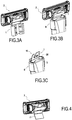
- Fig. 3A shows a schematic representation of a first perspective view (from a back side) of the razor connector 1 attached to a razor cartridge 2 according to examples of the present disclosure.
- the razor cartridge 2 comprises one or several openings (or slots) which are configured to receive the tines 11-13 and similarly as explained in connection with figures 2A-2C the razor connector and the razor cartridge may comprise an opening-protrusion assembly such that the razor connector 1 is securely connected to the cartridge 2.
- Fig. 3B shows a schematic representation of a second perspective view (from a lateral side) of the razor connector 1 of fig. 2A connected to a razor cartridge 1 and to a razor handle 3 according to examples of the present disclosure.
- Fig. 3C shows a schematic representation of a third perspective view (from a lateral side) of the razor connector 1 of fig. 3A and 3B connected only to a razor handle 3 according to examples of the present disclosure.
- the main body 20 is configured to be housed within a proximal end of the razor handle 3 (in view of axis Z in fig. 1 ) such that the upper portion 10 of the razor connector 1 extends outwardly or protrudes from the proximal end 6 of the razor handle 3.
- the main body 20 is formed such that it fills the space within an opening of the razor handle 3 to provide a reliable fitting or attachment of the razor connector 1 to the handle 3.
- the outer (3D) shape of the main body 20 may be adapted to the opening of the razor handle 3.Such a configuration of the main body allows pivoting of the razor cartridge 1 around an axis Z (cf. fig. 1 ) which is substantially perpendicular to a razor handle central axis and/or preferably substantially perpendicular to first axis X. First axis X and second axis z may intersect each other.
- the U-shaped ends 21 and 22 substantially as herein disclosed may thus be deformed when the razor cartridge 1 is rotated about the second axis Z. For example, during pivoting, one of the two U-shaped ends (depending on the direction of rotation) may be deformed towards the direction of rotation while the other may be deformed in a direction opposite to the direction of rotation thereby softening movement of the razor cartridge.
- the main body 20 may be configured to be non-removably attached to the razor handle 3, e.g. it may be glued to the handle 3.
- Fig. 4 shows a schematic representation of a perspective view (from a back side) of a razor connector 1 attached to a razor cartridge 2 according to an alternative example of the present disclosure.
- the upper portion 10 of the razor connector 1' has substantially the same structure as described above.
- the main body 20 of the razor connector 1' has the shape of the central portion 23 having the flat leaf or sheet shape, i.e. without the peripheral U-shaped ends. Accordingly, the manufacturing process may be slightly simplified (cf. to the embodiments described above). With this configuration of the razor connector, the razor cartridge is only capable of pivoting about the first axis X.
Landscapes
- Life Sciences & Earth Sciences (AREA)
- Forests & Forestry (AREA)
- Engineering & Computer Science (AREA)
- Mechanical Engineering (AREA)
- Knives (AREA)
- Packaging Of Annular Or Rod-Shaped Articles, Wearing Apparel, Cassettes, Or The Like (AREA)
- Dry Shavers And Clippers (AREA)
Abstract
Description
- The present disclosure concerns to razor connectors for connecting a razor cartridge to a razor handle. The present disclosure in particular relates to non-motorized razors comprising a razor cartridge and a razor handle connected to each other by such razor connectors.
- Known non-motorized razors comprise a rigid handle and a razor cartridge connected to it. In case the razor is non-disposable, i.e. configured to be re-usable, the razor cartridge can be detached from the handle such that it can be replaced by a new razor cartridge.
- It is further known to resiliently connect the razor cartridge to the razor handle, such that the razor cartridge is pivotable with respect to the handle. In this way shaving can be facilitated. For example,
US6223442B1 discloses a non-motorized razor having a rigid handle, a thin resilient leaf spring of flat cross section supported at a first end on the handle having a free end portion extending outwardly therefrom, and a generally rectangular blade-carrying razor head attached transversely at its approximate center on the free end portion of the spring in a plane approximately tangent to the plane of the spring with its lateral ends extending laterally outwardly. The spring free end portion is resiliently flexible in vertical and horizontal planes and capable of twisting along its central longitudinal axis. - Further razors with resiliently suspended or pivotable razor cartridges, in particular replaceable razor cartridges, are known from e.g.
US6311400B1 ,EP1671761B1 andUS20030079348A1 . - However, known razors comprise a rather complex attachment structure for attaching the razor cartridge to the handle. This increases manufacturing costs and deteriorates the reliability of the attachment structures.
- It thus remains desirable to provide improved razor connectors for connecting a razor cartridge to a razor handle.
- In a first aspect, a razor connector for connecting a razor cartridge to a razor handle is provided. The connector comprises a resilient element configured to connect a razor cartridge with a razor handle and to resiliently suspend the cartridge when attached to the handle. The resilient element has a main body configured to be attached to the razor handle. Further, the main body has a substantially flat portion and peripheral ends bent towards the flat portion.
- According to this aspect, the provision of the peripheral bent ends towards the flat portion provides a more versatile razor connector. For example, in a razor, when the cartridge and the handle are mounted to herein disclosed connector, the peripheral bent ends allow a resilient movement of the cartridge with respect to the handle. This occurs due to the resiliency of the bent ends.
- Another aspect provides for a razor comprising a razor cartridge comprising one or more blades and a razor handle connected to each other through the razor connector substantially as hereinbefore described.
- For example, the resilient element may be formed such that it achieves two functions: a removable attachment of the razor cartridge to the razor handle, and a resilient suspension of the razor cartridge in its attached state, i.e. when the razor cartridge is attached to the razor handle by the razor connector. In other words, a simple bent leaf may be used to achieve two different functions in the razor. In this way manufacturing costs can be reduced, as a simplified structure of the razor connector is used. At the same, due to this simple structure comprised of a sole component (i.e. the respectively formed leaf), the reliability of the razor connector is enhanced. For example, since the razor connector does not comprise several components that need to be connected to each other e.g. by any joints or any other means, the risk that the razor connector breaks into such different components is avoided or at least reduced.
- The peripheral ends may be U-shaped.
- For example, the formed leaf may have a bent cross section (in particular in a view directed from the proximal end to the distal end of the razor connector) such that the formed leaf defines a volume.
- In this way, in particular due to the bent ends, the resilient element may form a relatively bulky or voluminous object compared to the (originally flat) leaf of which the resilient element is formed. Hence, the resilient element may be easily manufactured from an originally flat resilient leaf (or sheet) and may have different forms. In examples, the resilient element may be formed such that it allows a secure attachment of the razor cartridge to the handle.
- The razor connector may consist of a leaf spring element.
- The razor connector may further comprise an upper portion configured to be attached to the razor cartridge, the upper portion being adjacent to the flat portion of the main body.
- The upper portion and the main body may be integrally formed.
- For example, at least a section of the razor connector between the proximal and the distal end (and/or between the main body and the upper portion) may be formed by the resilient leaf spring element. Accordingly, the razor connector may be pivotable about at least a first axis which is parallel to the extension of the razor cartridge and may be in a section of the razor connector between the proximal and the distal end.
- When the main body is attached to the razor handle, the upper portion of the razor connector may extend outwardly from the razor handle.
- In an example, the main body may be configured to be non-removably attached to the razor handle.
- In a further example, the main body may be configured to be located within a proximal end of the razor handle such that the upper portion of the leaf spring connector extends outwardly of the proximal end of the razor handle.
- Accordingly, the razor connector can be reliably secured to the razor handle.
- In still a further example, the main body may comprise a bent cross section such that the main body encloses a volume and fits into an opening within the proximal end of the razor handle.
- Accordingly, due to the bent form of the main body (in particular in a view directed from the proximal end to the distal end of the razor connector) the main body can fill the space within the opening of the razor handle to provide a reliable fitting or attachment of the razor connector to the handle.
- The upper portion may be formed as a clip, for example configured to removably attach the razor connector to the razor cartridge.
- In this manner, or as an alternative thereto, the upper portion may be formed as a fork having a plurality of tines, for example configured to be removably attached to the razor cartridge.
- Accordingly, the tines may be configured to be inserted into the razor cartridge, e.g. into openings of the razor cartridge, in order to provide a reliable attachment. At the same time the upper portion may be formed of the single resilient leaf which may be formed, e.g. cut, to constitute the fork form.
- The plurality of tines may be formed such that at least one tine is offset with regards to the others (these other tines) defining a two-dimensional area. In other words, a the at least one tine is offset to the two dimensional area defined by the other tines.
- For example, the plurality of tines may be formed such at least one tine is offset with regard to the others. In this way in a cross sectional view directed from the proximal end to the distal end of the razor connector the tines may define a two dimensional area.
- In other words, the tines (i.e. at least three tines) may be offset to each other in such a way that they are arranged in at least two different planes, or in still other words, such that the tines border a three-dimension space. In this way a three-dimensional connection of the razor connector to the razor cartridge may be achieved which ameliorates the fixation of the razor connector to the cartridge. This is in particular useful when the razor cartridge is pivoted around several orthogonal axis.
- At least one tine includes an opening configured to be coupled with a protrusion of the razor cartridge.
- The razor connector may be configured to extend from a proximal end where the razor handle is attached to a distal end where the razor cartridge is attached, and in a cross sectional view directed from the proximal end to the distal end of the razor connector, the peripheral ends may be bent towards each other forming facing U-shaped ends.
- In other words, when viewed from the proximal side toward the distal side of the razor connector, in a cross section of the main body the left and right ends of the resilient leaf forming the main body may be bent each to form a U-form. Said two U-forms may face each other. In other words they may be arranged symmetrically.
- Furthermore, such a configuration of the main body allows pivoting the razor cartridge around a second axis Z which is perpendicular to the razor handle and perpendicular to the extension of the razor cartridge and particularly perpendicular to the first axis X. The resilient ends having facing U-forms may namely be deformed when the cartridge is rotated about the axis Z. For example, during pivoting, one of the two U-forms (depending on the direction of rotation) is deformed towards the direction of rotation while the other is deformed in a direction opposite to the direction of rotation.
- The resilient leaf spring element may be bent and a blank and/or cut metal leaf. Accordingly, the leaf spring element may be simply manufactured what reduces the manufacturing costs of the razor connector.
- The present disclosure further relates to a razor comprising the razor connector as described above, a razor cartridge, and a razor handle. The razor handle may be connected to the razor cartridge through the razor connector.
- For example, the razor handle may extend into a first direction and the razor cartridge may extend into a second, perpendicular direction.
- In a further example, the handle may be releasably connected to the razor cartridge by the razor connector. In this way the handle may be reused by exchanging the razor cartridges.
- The razor cartridge may comprise an interconnecting member configured to be coupled to the razor connector such that the handle is releasably connected to the razor cartridge.
- For example, the razor connector may be directly connected to the cartridge through the interconnecting member, in case the handle is non removably attached to the cartridge
- The razor connector may be fixedly attached to the razor cartridge.
- It is intended that combinations of the above-described elements and those within the specification may be made, except where otherwise contradictory.
- It is to be understood that both the foregoing general description and the following detailed description are exemplary and explanatory only and are not restrictive of the disclosure, as claimed.
- The accompanying drawings, which are incorporated in and constitute a part of this specification, illustrate embodiments of the disclosure and together with the description, and serve to explain the principles thereof.
- Non-limiting examples of the present disclosure will be described in the following, with reference to the appended drawings, in which:
-
Fig. 1 shows a schematic representation of a front view of the razor connector attached to a razor cartridge according to embodiments of the present disclosure; -
Fig. 2A shows a schematic representation of a first perspective view (from a lower back side) of the razor connector according to embodiments of the present disclosure; -
Fig. 2B shows a schematic representation of a second perspective view (from a lateral side) of the razor connector offig. 2A ; -
Fig. 2C shows a schematic representation of a third perspective view (from a lower front side) of the razor connector offig. 2A and 2B ; -
Fig. 3A shows a schematic representation of a first perspective view (from a back side) of the razor connector attached to a razor cartridge according to embodiments of the present disclosure; -
Fig. 3B shows a schematic representation of a second perspective view (from a lateral side) of the razor connector offig. 2A connected to a razor cartridge and to a razor handle according to embodiments of the present disclosure; -
Fig. 3C shows a schematic representation of a third perspective view (from a lateral side) of the razor connector offig. 3A and RB connected only to a razor handle according to embodiments of the present disclosure; and -
Fig. 4 shows a schematic representation of a perspective view (from a back side) of a razor connector attached to a razor cartridge according to an alternative embodiment of the present disclosure. - Wherever possible, the same reference numbers will be used throughout the drawings to refer to the same or like parts.
- As used in this disclosure and in the appended claims, the singular forms "a", "an", and "the" include plural referents unless the content clearly dictates otherwise. As used in this disclosure and in the appended claims, the term "or" is generally employed in its sense including "and/or" unless the content clearly dictates otherwise.
- The detailed description and the drawings, which are not necessarily to scale, depict illustrative aspects and are not intended to limit the scope of the present disclosure. The illustrative aspects depicted are intended only as exemplary. Other alternatives, modifications, uses and/or equivalents thereof are possible. Furthermore, all possible combinations of the described examples are also covered.
-
Fig. 1 shows a schematic representation of a front view of arazor connector 1 attached to arazor cartridge 2 according to examples of the present disclosure. - The razor connector consists of a single resilient leaf which is formed, e.g. cut and bent. The razor connector thus comprises a resilient element made from the single resilient leaf. The resilient leaf is thus formed to a resilient element that it provides two functions at the same time: a removable attachment of the
razor cartridge 2 to the handle (not shown infig. 1 , cf. e.g.fig. 3B ), and a resilient suspension of thecartridge 2 in its attached state. -
Fig. 2A shows a schematic representation of a first perspective view (from a lower back side) of therazor connector 1 according to examples of the present disclosure.Fig. 2B shows a schematic representation of a second perspective view (from a lateral side) of therazor connector 1 offig. 2A. Fig. 2C shows a schematic representation of a third perspective view (from a lower front side) of therazor connector 1 offig. 2A and 2B . - The
razor connector 1 extends from a proximal end 4 (infig. 2A-C on a lower side) to a distal end 5 (along axis Z infig. 1 ). Therazor connector 1 comprises amain body 20 at itsproximal end 4, themain body 20 being configured to be attached to the razor handle, and anupper portion 10 at its distal end 5 (infig. 2A-C on a upper side), theupper portion 10 being configured to be removably attached to therazor cartridge 2. - As shown in particular in
fig. 2B or 2C , the formed leaf (razor connector 1) has a bent cross section in a plane x', y', or in other words, in a view directed from theproximal end 4 to thedistal end 5 of therazor connector 1. In this way the resulting razor connector fills a volume x', y', z', compared to the (originally flat) leaf from which the resilient element is formed thereby forming a bulky razor connector. - At least the section of the razor connector (cf. e.g. the region where axis X" is indicated in
fig. 2A ) between themain body 20 and theupper portion 10 is configured to function as a resilient spring element in therazor connector 1. Accordingly, therazor connector 1 may be pivotable about at least a first axis X" (cf. alsofig. 2A ) which may be parallel to the extension of the razor cartridge and substantially parallel to the blades and may be in a section of the razor connector between the proximal and the distal end. - Further in these examples, the
main body 20 comprises a bent cross section defining a volume (cf. e.g.fig. 2B ) that in use, i.e. when the razor cartridge and the razor handle are put together by the razor connector, fits into an opening within the proximal end of the razor handle 3 (cf. e.g.fig. 3C . Accordingly, due to the bent shape of themain body 20, themain body 20 is further comprised of acentral portion 23 having a flat shape and of peripheral ends (i.e. in its lateral left and right portions in the example offig. 2A ) bent towards each other forming facing U-shaped ends 21, 22. Hence, in a z'-direction (cf.fig. 2B ), i.e. in a cross sectional view directed from the proximal end to the distal end of the razor connector, themain body 20 comprises peripheral ends bent to form facing U-shaped ends 21, 22. - In some examples, the
upper portion 10 is formed as a clip configured to removably attach therazor connector 1 to therazor cartridge 2. In more examples, the clip may be also regarded as a fork having a plurality of tines 11-13 configured to be removably attached to therazor cartridge 2. - In examples, in order to form a clip the plurality of tines 11-13 may be formed such at least one tine is offset with regard to the others (cf. in particular
fig. 2B ). In this way the tines 11-13 are arranged in at least two different planes. E.g. as illustrated in the example offigure 2C , thecentral tine 12 may be in a first plane and theperipheral tines main body 20. - In some examples as further shown in
figures 2A-2C , thecentral tine 12 includes anopening 14 configured to engage with a protrusion of the razor cartridge. Furthermore, thecentral tine 12 may be slightly longer that the razor cartridge such that when mated, thecentral tine 12 protrudes out of aninsertion opening 14 of the razor cartridge (cf. e.g.fig. 3A ). In this way theopening 14 engages with the respective protrusion of therazor cartridge 2 keeping the cartridge in its position and ready to use. Only when thecentral tine 12 is slightly bended in an appropriate manner in an operation state of the razor, the protrusion of the cartridge and theopening 14 of therazor connector 1 can be disengaged, such that therazor cartridge 2 can be removed from the razor connector and thus from the handle. Hence, theconnector 1 allows a secure connection of thecartridge 2 to thehandle 3. - In one example the cartridge may be non-removably attached to the handle. In this case, the
upper portion 10 comprising the tines 11-13 and theopening 14, is fixedly attached to the razor cartridge, for example by ultrasonic welding, laser welding, gluing or by any other suitable means. -
Fig. 3A shows a schematic representation of a first perspective view (from a back side) of therazor connector 1 attached to arazor cartridge 2 according to examples of the present disclosure. As shown in this figure, therazor cartridge 2 comprises one or several openings (or slots) which are configured to receive the tines 11-13 and similarly as explained in connection withfigures 2A-2C the razor connector and the razor cartridge may comprise an opening-protrusion assembly such that therazor connector 1 is securely connected to thecartridge 2. -
Fig. 3B shows a schematic representation of a second perspective view (from a lateral side) of therazor connector 1 offig. 2A connected to arazor cartridge 1 and to arazor handle 3 according to examples of the present disclosure.Fig. 3C shows a schematic representation of a third perspective view (from a lateral side) of therazor connector 1 offig. 3A and 3B connected only to arazor handle 3 according to examples of the present disclosure. - As shown, in particular in
fig. 3C , themain body 20 is configured to be housed within a proximal end of the razor handle 3 (in view of axis Z infig. 1 ) such that theupper portion 10 of therazor connector 1 extends outwardly or protrudes from theproximal end 6 of therazor handle 3. - In examples, the
main body 20 is formed such that it fills the space within an opening of the razor handle 3 to provide a reliable fitting or attachment of therazor connector 1 to thehandle 3. In other words, the outer (3D) shape of themain body 20 may be adapted to the opening of the razor handle 3.Such a configuration of the main body allows pivoting of therazor cartridge 1 around an axis Z (cf.fig. 1 ) which is substantially perpendicular to a razor handle central axis and/or preferably substantially perpendicular to first axis X. First axis X and second axis z may intersect each other. The U-shaped ends 21 and 22 substantially as herein disclosed may thus be deformed when therazor cartridge 1 is rotated about the second axis Z. For example, during pivoting, one of the two U-shaped ends (depending on the direction of rotation) may be deformed towards the direction of rotation while the other may be deformed in a direction opposite to the direction of rotation thereby softening movement of the razor cartridge. - In some examples, the
main body 20 may be configured to be non-removably attached to therazor handle 3, e.g. it may be glued to thehandle 3. -
Fig. 4 shows a schematic representation of a perspective view (from a back side) of arazor connector 1 attached to arazor cartridge 2 according to an alternative example of the present disclosure. - In this example, the
upper portion 10 of the razor connector 1' has substantially the same structure as described above. However, themain body 20 of the razor connector 1' has the shape of thecentral portion 23 having the flat leaf or sheet shape, i.e. without the peripheral U-shaped ends. Accordingly, the manufacturing process may be slightly simplified (cf. to the embodiments described above). With this configuration of the razor connector, the razor cartridge is only capable of pivoting about the first axis X. - Throughout the description, including the claims, the term "comprising a" should be understood as being synonymous with "comprising at least one" unless otherwise stated. In addition, any range set forth in the description, including the claims should be understood as including its end value(s) unless otherwise stated. Specific values for described elements should be understood to be within accepted manufacturing or industry tolerances known to one of skill in the art, and any use of the terms "substantially" and/or "approximately" and/or "generally" should be understood to mean falling within such accepted tolerances.
- Although the present disclosure herein has been described with reference to particular examples, it is to be understood that these examples are merely illustrative of the principles and applications of the present disclosure.
- It is intended that the specification and examples be considered as exemplary only, with a true scope of the disclosure being indicated by the following claims.
Claims (15)
- A razor connector for a razor, the connector comprising:a resilient element configured to connect a razor cartridge with a razor handle and to resiliently suspend the cartridge when attached to the handle,wherein the resilient element has a main body configured to be attached to the razor handle, the main body having a substantially flat portion and peripheral ends bent towards the flat portion.
- The razor connector according to claim 1, wherein
the peripheral ends are U-shaped. - The razor connector according to claim 1 or 2, wherein
the razor connector consists of a leaf spring element. - The razor connector according to any of claims 1 to 3,
further comprising an upper portion configured to be attached to the razor cartridge, the upper portion being adjacent to the flat portion of the main body. - The razor connector according to claim 4 wherein
the upper portion and the main body are integrally formed. - The razor connector according to claim 4 or 5, wherein
when the main body is attached to the razor handle, the upper portion of the razor connector extends outwardly from the razor handle. - The razor connector according to any of claims 4 to 6, wherein
the upper portion is formed as a clip. - The razor connector according to any of claims 4 to 7, wherein
the upper portion is formed as a fork having a plurality of tines. - The razor connector according to claim 8, wherein
the plurality of tines is formed such that at least one tine is offset with regards to the others defining a two-dimensional area. - The razor connector according to claim 8 or 9, wherein
at least one tine includes an opening configured to be coupled with a protrusion of the razor cartridge. - The razor connector according to any one of the preceding claims,
wherein the razor connector extends from a proximal end configured to be attached to the razor handle to a distal end configured to be attached to the razor cartridge, and
in a cross sectional view directed from the proximal end to the distal end of the razor connector, the peripheral ends are bent towards each other forming facing U-shaped ends. - The razor connector according to any one of the preceding claims,
wherein
the resilient element is a bent blank and/or cut metal leaf. - A razor comprising:a razor connector according to any one of the preceding claims,a razor cartridge comprising one or more blades, anda razor handle connected to the razor cartridge through the razor connector.
- The razor according to claim 13, wherein
the razor cartridge comprises an interconnecting member configured to be coupled to the razor connector such that the handle is releasably connected to the razor cartridge. - The razor according to claim 13 or 14 wherein
the razor connector is fixedly attached to the razor cartridge.
Priority Applications (7)
| Application Number | Priority Date | Filing Date | Title |
|---|---|---|---|
| EP18183236.1A EP3593963B1 (en) | 2018-07-12 | 2018-07-12 | Razor connectors |
| CN201980039687.0A CN112262029B (en) | 2018-07-12 | 2019-07-12 | Razor connector |
| BR112020025780-0A BR112020025780B1 (en) | 2018-07-12 | 2019-07-12 | KNIFE CONNECTORS |
| PCT/EP2019/068791 WO2020011963A1 (en) | 2018-07-12 | 2019-07-12 | Razor connectors |
| US17/251,075 US11759964B2 (en) | 2018-07-12 | 2019-07-12 | Razor connectors |
| MX2020013873A MX2020013873A (en) | 2018-07-12 | 2019-07-12 | Razor connectors. |
| KR1020207035521A KR102883026B1 (en) | 2018-07-12 | 2019-07-12 | Razor connector |
Applications Claiming Priority (1)
| Application Number | Priority Date | Filing Date | Title |
|---|---|---|---|
| EP18183236.1A EP3593963B1 (en) | 2018-07-12 | 2018-07-12 | Razor connectors |
Publications (2)
| Publication Number | Publication Date |
|---|---|
| EP3593963A1 true EP3593963A1 (en) | 2020-01-15 |
| EP3593963B1 EP3593963B1 (en) | 2022-08-31 |
Family
ID=62948050
Family Applications (1)
| Application Number | Title | Priority Date | Filing Date |
|---|---|---|---|
| EP18183236.1A Active EP3593963B1 (en) | 2018-07-12 | 2018-07-12 | Razor connectors |
Country Status (6)
| Country | Link |
|---|---|
| US (1) | US11759964B2 (en) |
| EP (1) | EP3593963B1 (en) |
| KR (1) | KR102883026B1 (en) |
| CN (1) | CN112262029B (en) |
| MX (1) | MX2020013873A (en) |
| WO (1) | WO2020011963A1 (en) |
Families Citing this family (8)
| Publication number | Priority date | Publication date | Assignee | Title |
|---|---|---|---|---|
| EP3717186B1 (en) * | 2017-11-28 | 2022-01-05 | Edgewell Personal Care Brands, LLC | Razor handle |
| EP3774220A1 (en) | 2018-03-30 | 2021-02-17 | The Gillette Company LLC | Shaving razor system including skin interconnect member |
| JP2021516125A (en) * | 2018-03-30 | 2021-07-01 | ザ ジレット カンパニー リミテッド ライアビリティ カンパニーThe Gillette Company Llc | Shaving razor system including skin interconnect members |
| EP3771530B1 (en) * | 2019-07-31 | 2024-08-28 | BIC Violex Single Member S.A. | Mechanical assembly of a skin care device, skin care device and process for manufacturing thereof |
| EP3842196B1 (en) * | 2019-12-23 | 2023-09-13 | BIC Violex Single Member S.A. | Coupling mechanism |
| CN216658034U (en) * | 2021-11-03 | 2022-06-03 | 深圳诺泰科电子有限公司 | Shaver |
| EP4385687B1 (en) * | 2022-12-14 | 2026-06-17 | BIC Violex Single Member S.A. | Shaving device |
| WO2025065749A1 (en) * | 2023-09-29 | 2025-04-03 | Edgewell Personal Care Brands, Llc | Shaving razor and related assembly |
Citations (7)
| Publication number | Priority date | Publication date | Assignee | Title |
|---|---|---|---|---|
| US4128937A (en) * | 1976-08-06 | 1978-12-12 | Adorney Charles S | Safety razor with serpentine handle |
| EP0429174A2 (en) * | 1989-11-17 | 1991-05-29 | Warner-Lambert Company | Pivoting safety razor assembly |
| WO1998023417A1 (en) * | 1996-11-22 | 1998-06-04 | Societe Bic, S.A. | Razor and razor head |
| US6223442B1 (en) | 1999-08-19 | 2001-05-01 | William Alvarez Pina | Non-motorized razor with spring-supported head |
| US6311400B1 (en) | 1997-07-22 | 2001-11-06 | The Gillette Company | Safety razor |
| US20030079348A1 (en) | 2001-11-01 | 2003-05-01 | Follo Thomas A. | Razor assembly with replaceable cartridge |
| EP1671761B1 (en) | 2004-12-17 | 2008-03-05 | Feintechnik GmbH Eisfeld | Shaving razor for supporting a detachable shaving unit |
Family Cites Families (31)
| Publication number | Priority date | Publication date | Assignee | Title |
|---|---|---|---|---|
| GB1460732A (en) * | 1973-03-01 | 1977-01-06 | Gillette Co | Safety razor |
| US4152828A (en) * | 1978-03-29 | 1979-05-08 | Lund Lloyd W | Razor having variable angle and tilt of its blade |
| JPS596675B2 (en) * | 1980-10-20 | 1984-02-14 | 株式会社貝印刃物開発センター | safety razor |
| US4780959A (en) | 1987-01-27 | 1988-11-01 | Sinka Laslo B | Razor adaptor |
| US4791724A (en) * | 1987-06-04 | 1988-12-20 | Jack Dumas | Wedge shaped razor apparatus |
| US5050301A (en) * | 1990-09-19 | 1991-09-24 | The Gillette Company | Razor assembly |
| GB9208098D0 (en) * | 1992-04-13 | 1992-05-27 | Gillette Co | Razor with movable cartridge |
| US5560106A (en) * | 1993-11-09 | 1996-10-01 | Armbruster; Joseph M. | Resilient floating head razor |
| US5600887A (en) * | 1995-05-26 | 1997-02-11 | Olson; Brad | Flexible easy-rinsing razor |
| US5953825A (en) * | 1996-01-16 | 1999-09-21 | The Gillette Company | Safety razors |
| US6122826A (en) * | 1998-04-22 | 2000-09-26 | Warner-Lambert Company | Disposable cartridge holder for single direction pivoting cartridge |
| US6615498B1 (en) * | 2000-03-13 | 2003-09-09 | Warner-Lambert Company | Flexible member for a shaving razor |
| US20040177519A1 (en) * | 2003-03-14 | 2004-09-16 | Louis D. Tomassetti | Flexible razor and dispenser with pivoting head |
| US8033023B2 (en) | 2004-10-20 | 2011-10-11 | The Gillette Company | Shaving razors and cartridges |
| US7681320B2 (en) | 2004-12-15 | 2010-03-23 | The Gillette Company | Shaving razors and razor cartridges |
| EP1899119A1 (en) * | 2005-05-20 | 2008-03-19 | Eveready Battery Company, Inc. | Razor cartridge having a decoupled guard bar |
| PL1907174T3 (en) * | 2005-06-20 | 2010-10-29 | Eveready Battery Inc | Shaving implement having a cap forward pivot |
| US7770294B2 (en) * | 2007-08-30 | 2010-08-10 | The Gillette Company | Razor with blade unit biasing member |
| US8671577B2 (en) * | 2008-12-03 | 2014-03-18 | Thomas A. Brown | Razor with independent suspension |
| RU2548351C2 (en) * | 2009-11-12 | 2015-04-20 | Конинклейке Филипс Электроникс Н.В. | Hair clipping device with turning mechanism |
| CN201645522U (en) | 2010-03-03 | 2010-11-24 | 任向荣 | Shaver handle and shaver employing same |
| US8898909B2 (en) * | 2010-08-25 | 2014-12-02 | Spectrum Brands, Inc. | Electric shaver |
| WO2014039264A1 (en) * | 2012-09-10 | 2014-03-13 | Eveready Battery Company, Inc | Safety razor |
| DE102013213874A1 (en) * | 2013-07-16 | 2015-02-19 | Beiersdorf Ag | Razor with spring-loaded holder |
| ES2660443T3 (en) | 2014-01-31 | 2018-03-22 | Feintechnik Gmbh Eisfeld | Razor with a handle and a rotating cutting unit |
| US20170165853A1 (en) * | 2015-12-15 | 2017-06-15 | Yvonne Chee On Li | Razor with mirror |
| EP3571025B1 (en) * | 2017-01-17 | 2021-08-11 | BIC-Violex S.A. | A connector adapted for wet shaving cartridges pivotable about two axes |
| KR101894213B1 (en) * | 2017-11-21 | 2018-09-04 | 주식회사 도루코 | Razor assembly |
| EP3513919B1 (en) * | 2018-01-17 | 2020-11-18 | BIC Violex S.A. | Shaving blade assembly |
| EP3863818B1 (en) * | 2018-10-12 | 2023-11-08 | The Gillette Company LLC | Razor |
| KR102323315B1 (en) * | 2019-12-18 | 2021-11-08 | 주식회사 도루코 | Razor |
-
2018
- 2018-07-12 EP EP18183236.1A patent/EP3593963B1/en active Active
-
2019
- 2019-07-12 CN CN201980039687.0A patent/CN112262029B/en active Active
- 2019-07-12 US US17/251,075 patent/US11759964B2/en active Active
- 2019-07-12 MX MX2020013873A patent/MX2020013873A/en unknown
- 2019-07-12 KR KR1020207035521A patent/KR102883026B1/en active Active
- 2019-07-12 WO PCT/EP2019/068791 patent/WO2020011963A1/en not_active Ceased
Patent Citations (7)
| Publication number | Priority date | Publication date | Assignee | Title |
|---|---|---|---|---|
| US4128937A (en) * | 1976-08-06 | 1978-12-12 | Adorney Charles S | Safety razor with serpentine handle |
| EP0429174A2 (en) * | 1989-11-17 | 1991-05-29 | Warner-Lambert Company | Pivoting safety razor assembly |
| WO1998023417A1 (en) * | 1996-11-22 | 1998-06-04 | Societe Bic, S.A. | Razor and razor head |
| US6311400B1 (en) | 1997-07-22 | 2001-11-06 | The Gillette Company | Safety razor |
| US6223442B1 (en) | 1999-08-19 | 2001-05-01 | William Alvarez Pina | Non-motorized razor with spring-supported head |
| US20030079348A1 (en) | 2001-11-01 | 2003-05-01 | Follo Thomas A. | Razor assembly with replaceable cartridge |
| EP1671761B1 (en) | 2004-12-17 | 2008-03-05 | Feintechnik GmbH Eisfeld | Shaving razor for supporting a detachable shaving unit |
Also Published As
| Publication number | Publication date |
|---|---|
| EP3593963B1 (en) | 2022-08-31 |
| US20210122072A1 (en) | 2021-04-29 |
| US11759964B2 (en) | 2023-09-19 |
| CN112262029A (en) | 2021-01-22 |
| WO2020011963A1 (en) | 2020-01-16 |
| CN112262029B (en) | 2022-11-11 |
| MX2020013873A (en) | 2021-05-27 |
| KR102883026B1 (en) | 2025-11-06 |
| BR112020025780A2 (en) | 2021-03-16 |
| KR20210030269A (en) | 2021-03-17 |
Similar Documents
| Publication | Publication Date | Title |
|---|---|---|
| EP3593963B1 (en) | Razor connectors | |
| US10543610B2 (en) | Shaving blade cartridge, a shaver comprising such shaving blade cartridge and a method of manufacturing such a shaving blade cartridge | |
| US10751894B2 (en) | Shaving blade cartridge | |
| EP3083163B1 (en) | A shaving blade cartridge | |
| ES2610136T3 (en) | Razor handle with rotatable part | |
| JP6499294B2 (en) | Shaving blade cartridge and shaver equipped with the shaving blade cartridge | |
| EP1188526A2 (en) | Razor blade system | |
| EP3481607B1 (en) | Razor system | |
| EP0293683B1 (en) | Improvement in or relating to safety razors | |
| JP4676003B2 (en) | Safety razor | |
| CN109834739B (en) | Razor blade holder and razor blade holder assembly | |
| EP0240357A1 (en) | Pivot joint | |
| KR102494626B1 (en) | Hybrid Windshield Wiper Blades | |
| EP3378612A1 (en) | Razor cartridge | |
| AU1841699A (en) | Disposable cartridge holder for single direction pivoting cartridge | |
| CN108025446B (en) | Double-edged blade capable of being broken | |
| EP3496915B1 (en) | Handle for a razor | |
| EP3072757A1 (en) | Connector element for connecting together windscreen wiper blades and their operating arms | |
| JPH07263046A (en) | Board lock clip | |
| BR112020025780B1 (en) | KNIFE CONNECTORS | |
| KR102473133B1 (en) | Razor Cartridge | |
| JP6917209B2 (en) | Wiper blade | |
| JPS5850756B2 (en) | Replaceable blade razor holder | |
| EP0073853A2 (en) | Shaving implement | |
| PL161544B1 (en) | The razor |
Legal Events
| Date | Code | Title | Description |
|---|---|---|---|
| PUAI | Public reference made under article 153(3) epc to a published international application that has entered the european phase |
Free format text: ORIGINAL CODE: 0009012 |
|
| STAA | Information on the status of an ep patent application or granted ep patent |
Free format text: STATUS: THE APPLICATION HAS BEEN PUBLISHED |
|
| AK | Designated contracting states |
Kind code of ref document: A1 Designated state(s): AL AT BE BG CH CY CZ DE DK EE ES FI FR GB GR HR HU IE IS IT LI LT LU LV MC MK MT NL NO PL PT RO RS SE SI SK SM TR |
|
| AX | Request for extension of the european patent |
Extension state: BA ME |
|
| STAA | Information on the status of an ep patent application or granted ep patent |
Free format text: STATUS: REQUEST FOR EXAMINATION WAS MADE |
|
| 17P | Request for examination filed |
Effective date: 20200710 |
|
| RBV | Designated contracting states (corrected) |
Designated state(s): AL AT BE BG CH CY CZ DE DK EE ES FI FR GB GR HR HU IE IS IT LI LT LU LV MC MK MT NL NO PL PT RO RS SE SI SK SM TR |
|
| GRAP | Despatch of communication of intention to grant a patent |
Free format text: ORIGINAL CODE: EPIDOSNIGR1 |
|
| STAA | Information on the status of an ep patent application or granted ep patent |
Free format text: STATUS: GRANT OF PATENT IS INTENDED |
|
| RIC1 | Information provided on ipc code assigned before grant |
Ipc: B26B 21/52 20060101ALI20220222BHEP Ipc: B26B 21/22 20060101AFI20220222BHEP |
|
| INTG | Intention to grant announced |
Effective date: 20220310 |
|
| RAP3 | Party data changed (applicant data changed or rights of an application transferred) |
Owner name: BIC VIOLEX SINGLE MEMBER S.A. |
|
| GRAS | Grant fee paid |
Free format text: ORIGINAL CODE: EPIDOSNIGR3 |
|
| GRAA | (expected) grant |
Free format text: ORIGINAL CODE: 0009210 |
|
| STAA | Information on the status of an ep patent application or granted ep patent |
Free format text: STATUS: THE PATENT HAS BEEN GRANTED |
|
| AK | Designated contracting states |
Kind code of ref document: B1 Designated state(s): AL AT BE BG CH CY CZ DE DK EE ES FI FR GB GR HR HU IE IS IT LI LT LU LV MC MK MT NL NO PL PT RO RS SE SI SK SM TR |
|
| REG | Reference to a national code |
Ref country code: CH Ref legal event code: EP Ref country code: GB Ref legal event code: FG4D |
|
| REG | Reference to a national code |
Ref country code: AT Ref legal event code: REF Ref document number: 1514989 Country of ref document: AT Kind code of ref document: T Effective date: 20220915 Ref country code: DE Ref legal event code: R096 Ref document number: 602018039926 Country of ref document: DE |
|
| REG | Reference to a national code |
Ref country code: IE Ref legal event code: FG4D |
|
| REG | Reference to a national code |
Ref country code: LT Ref legal event code: MG9D |
|
| REG | Reference to a national code |
Ref country code: NL Ref legal event code: MP Effective date: 20220831 |
|
| PG25 | Lapsed in a contracting state [announced via postgrant information from national office to epo] |
Ref country code: SE Free format text: LAPSE BECAUSE OF FAILURE TO SUBMIT A TRANSLATION OF THE DESCRIPTION OR TO PAY THE FEE WITHIN THE PRESCRIBED TIME-LIMIT Effective date: 20220831 Ref country code: RS Free format text: LAPSE BECAUSE OF FAILURE TO SUBMIT A TRANSLATION OF THE DESCRIPTION OR TO PAY THE FEE WITHIN THE PRESCRIBED TIME-LIMIT Effective date: 20220831 Ref country code: NO Free format text: LAPSE BECAUSE OF FAILURE TO SUBMIT A TRANSLATION OF THE DESCRIPTION OR TO PAY THE FEE WITHIN THE PRESCRIBED TIME-LIMIT Effective date: 20221130 Ref country code: LV Free format text: LAPSE BECAUSE OF FAILURE TO SUBMIT A TRANSLATION OF THE DESCRIPTION OR TO PAY THE FEE WITHIN THE PRESCRIBED TIME-LIMIT Effective date: 20220831 Ref country code: LT Free format text: LAPSE BECAUSE OF FAILURE TO SUBMIT A TRANSLATION OF THE DESCRIPTION OR TO PAY THE FEE WITHIN THE PRESCRIBED TIME-LIMIT Effective date: 20220831 Ref country code: FI Free format text: LAPSE BECAUSE OF FAILURE TO SUBMIT A TRANSLATION OF THE DESCRIPTION OR TO PAY THE FEE WITHIN THE PRESCRIBED TIME-LIMIT Effective date: 20220831 |
|
| REG | Reference to a national code |
Ref country code: AT Ref legal event code: MK05 Ref document number: 1514989 Country of ref document: AT Kind code of ref document: T Effective date: 20220831 |
|
| PG25 | Lapsed in a contracting state [announced via postgrant information from national office to epo] |
Ref country code: PL Free format text: LAPSE BECAUSE OF FAILURE TO SUBMIT A TRANSLATION OF THE DESCRIPTION OR TO PAY THE FEE WITHIN THE PRESCRIBED TIME-LIMIT Effective date: 20220831 Ref country code: IS Free format text: LAPSE BECAUSE OF FAILURE TO SUBMIT A TRANSLATION OF THE DESCRIPTION OR TO PAY THE FEE WITHIN THE PRESCRIBED TIME-LIMIT Effective date: 20221231 Ref country code: HR Free format text: LAPSE BECAUSE OF FAILURE TO SUBMIT A TRANSLATION OF THE DESCRIPTION OR TO PAY THE FEE WITHIN THE PRESCRIBED TIME-LIMIT Effective date: 20220831 Ref country code: GR Free format text: LAPSE BECAUSE OF FAILURE TO SUBMIT A TRANSLATION OF THE DESCRIPTION OR TO PAY THE FEE WITHIN THE PRESCRIBED TIME-LIMIT Effective date: 20221201 |
|
| PG25 | Lapsed in a contracting state [announced via postgrant information from national office to epo] |
Ref country code: SM Free format text: LAPSE BECAUSE OF FAILURE TO SUBMIT A TRANSLATION OF THE DESCRIPTION OR TO PAY THE FEE WITHIN THE PRESCRIBED TIME-LIMIT Effective date: 20220831 Ref country code: RO Free format text: LAPSE BECAUSE OF FAILURE TO SUBMIT A TRANSLATION OF THE DESCRIPTION OR TO PAY THE FEE WITHIN THE PRESCRIBED TIME-LIMIT Effective date: 20220831 Ref country code: PT Free format text: LAPSE BECAUSE OF FAILURE TO SUBMIT A TRANSLATION OF THE DESCRIPTION OR TO PAY THE FEE WITHIN THE PRESCRIBED TIME-LIMIT Effective date: 20230102 Ref country code: ES Free format text: LAPSE BECAUSE OF FAILURE TO SUBMIT A TRANSLATION OF THE DESCRIPTION OR TO PAY THE FEE WITHIN THE PRESCRIBED TIME-LIMIT Effective date: 20220831 Ref country code: DK Free format text: LAPSE BECAUSE OF FAILURE TO SUBMIT A TRANSLATION OF THE DESCRIPTION OR TO PAY THE FEE WITHIN THE PRESCRIBED TIME-LIMIT Effective date: 20220831 Ref country code: CZ Free format text: LAPSE BECAUSE OF FAILURE TO SUBMIT A TRANSLATION OF THE DESCRIPTION OR TO PAY THE FEE WITHIN THE PRESCRIBED TIME-LIMIT Effective date: 20220831 Ref country code: AT Free format text: LAPSE BECAUSE OF FAILURE TO SUBMIT A TRANSLATION OF THE DESCRIPTION OR TO PAY THE FEE WITHIN THE PRESCRIBED TIME-LIMIT Effective date: 20220831 |
|
| PG25 | Lapsed in a contracting state [announced via postgrant information from national office to epo] |
Ref country code: SK Free format text: LAPSE BECAUSE OF FAILURE TO SUBMIT A TRANSLATION OF THE DESCRIPTION OR TO PAY THE FEE WITHIN THE PRESCRIBED TIME-LIMIT Effective date: 20220831 Ref country code: EE Free format text: LAPSE BECAUSE OF FAILURE TO SUBMIT A TRANSLATION OF THE DESCRIPTION OR TO PAY THE FEE WITHIN THE PRESCRIBED TIME-LIMIT Effective date: 20220831 |
|
| REG | Reference to a national code |
Ref country code: DE Ref legal event code: R097 Ref document number: 602018039926 Country of ref document: DE |
|
| PG25 | Lapsed in a contracting state [announced via postgrant information from national office to epo] |
Ref country code: NL Free format text: LAPSE BECAUSE OF FAILURE TO SUBMIT A TRANSLATION OF THE DESCRIPTION OR TO PAY THE FEE WITHIN THE PRESCRIBED TIME-LIMIT Effective date: 20220831 Ref country code: AL Free format text: LAPSE BECAUSE OF FAILURE TO SUBMIT A TRANSLATION OF THE DESCRIPTION OR TO PAY THE FEE WITHIN THE PRESCRIBED TIME-LIMIT Effective date: 20220831 |
|
| PLBE | No opposition filed within time limit |
Free format text: ORIGINAL CODE: 0009261 |
|
| STAA | Information on the status of an ep patent application or granted ep patent |
Free format text: STATUS: NO OPPOSITION FILED WITHIN TIME LIMIT |
|
| 26N | No opposition filed |
Effective date: 20230601 |
|
| PG25 | Lapsed in a contracting state [announced via postgrant information from national office to epo] |
Ref country code: SI Free format text: LAPSE BECAUSE OF FAILURE TO SUBMIT A TRANSLATION OF THE DESCRIPTION OR TO PAY THE FEE WITHIN THE PRESCRIBED TIME-LIMIT Effective date: 20220831 |
|
| PG25 | Lapsed in a contracting state [announced via postgrant information from national office to epo] |
Ref country code: MC Free format text: LAPSE BECAUSE OF FAILURE TO SUBMIT A TRANSLATION OF THE DESCRIPTION OR TO PAY THE FEE WITHIN THE PRESCRIBED TIME-LIMIT Effective date: 20220831 |
|
| PG25 | Lapsed in a contracting state [announced via postgrant information from national office to epo] |
Ref country code: MC Free format text: LAPSE BECAUSE OF FAILURE TO SUBMIT A TRANSLATION OF THE DESCRIPTION OR TO PAY THE FEE WITHIN THE PRESCRIBED TIME-LIMIT Effective date: 20220831 |
|
| REG | Reference to a national code |
Ref country code: CH Ref legal event code: PL |
|
| REG | Reference to a national code |
Ref country code: BE Ref legal event code: MM Effective date: 20230731 |
|
| PG25 | Lapsed in a contracting state [announced via postgrant information from national office to epo] |
Ref country code: LU Free format text: LAPSE BECAUSE OF NON-PAYMENT OF DUE FEES Effective date: 20230712 |
|
| PG25 | Lapsed in a contracting state [announced via postgrant information from national office to epo] |
Ref country code: LU Free format text: LAPSE BECAUSE OF NON-PAYMENT OF DUE FEES Effective date: 20230712 |
|
| REG | Reference to a national code |
Ref country code: IE Ref legal event code: MM4A |
|
| PG25 | Lapsed in a contracting state [announced via postgrant information from national office to epo] |
Ref country code: CH Free format text: LAPSE BECAUSE OF NON-PAYMENT OF DUE FEES Effective date: 20230731 |
|
| PG25 | Lapsed in a contracting state [announced via postgrant information from national office to epo] |
Ref country code: IT Free format text: LAPSE BECAUSE OF FAILURE TO SUBMIT A TRANSLATION OF THE DESCRIPTION OR TO PAY THE FEE WITHIN THE PRESCRIBED TIME-LIMIT Effective date: 20220831 Ref country code: BE Free format text: LAPSE BECAUSE OF NON-PAYMENT OF DUE FEES Effective date: 20230731 |
|
| PG25 | Lapsed in a contracting state [announced via postgrant information from national office to epo] |
Ref country code: IE Free format text: LAPSE BECAUSE OF NON-PAYMENT OF DUE FEES Effective date: 20230712 |
|
| PG25 | Lapsed in a contracting state [announced via postgrant information from national office to epo] |
Ref country code: IE Free format text: LAPSE BECAUSE OF NON-PAYMENT OF DUE FEES Effective date: 20230712 |
|
| PG25 | Lapsed in a contracting state [announced via postgrant information from national office to epo] |
Ref country code: BG Free format text: LAPSE BECAUSE OF FAILURE TO SUBMIT A TRANSLATION OF THE DESCRIPTION OR TO PAY THE FEE WITHIN THE PRESCRIBED TIME-LIMIT Effective date: 20220831 |
|
| PG25 | Lapsed in a contracting state [announced via postgrant information from national office to epo] |
Ref country code: BG Free format text: LAPSE BECAUSE OF FAILURE TO SUBMIT A TRANSLATION OF THE DESCRIPTION OR TO PAY THE FEE WITHIN THE PRESCRIBED TIME-LIMIT Effective date: 20220831 |
|
| PG25 | Lapsed in a contracting state [announced via postgrant information from national office to epo] |
Ref country code: CY Free format text: LAPSE BECAUSE OF FAILURE TO SUBMIT A TRANSLATION OF THE DESCRIPTION OR TO PAY THE FEE WITHIN THE PRESCRIBED TIME-LIMIT; INVALID AB INITIO Effective date: 20180712 |
|
| PG25 | Lapsed in a contracting state [announced via postgrant information from national office to epo] |
Ref country code: HU Free format text: LAPSE BECAUSE OF FAILURE TO SUBMIT A TRANSLATION OF THE DESCRIPTION OR TO PAY THE FEE WITHIN THE PRESCRIBED TIME-LIMIT; INVALID AB INITIO Effective date: 20180712 |
|
| PGFP | Annual fee paid to national office [announced via postgrant information from national office to epo] |
Ref country code: DE Payment date: 20250722 Year of fee payment: 8 |
|
| PGFP | Annual fee paid to national office [announced via postgrant information from national office to epo] |
Ref country code: GB Payment date: 20250724 Year of fee payment: 8 |
|
| PGFP | Annual fee paid to national office [announced via postgrant information from national office to epo] |
Ref country code: FR Payment date: 20250723 Year of fee payment: 8 |
|
| PG25 | Lapsed in a contracting state [announced via postgrant information from national office to epo] |
Ref country code: TR Free format text: LAPSE BECAUSE OF FAILURE TO SUBMIT A TRANSLATION OF THE DESCRIPTION OR TO PAY THE FEE WITHIN THE PRESCRIBED TIME-LIMIT Effective date: 20220831 |