EP3863818B1 - Razor - Google Patents
Razor Download PDFInfo
- Publication number
- EP3863818B1 EP3863818B1 EP19794812.8A EP19794812A EP3863818B1 EP 3863818 B1 EP3863818 B1 EP 3863818B1 EP 19794812 A EP19794812 A EP 19794812A EP 3863818 B1 EP3863818 B1 EP 3863818B1
- Authority
- EP
- European Patent Office
- Prior art keywords
- razor
- projections
- central core
- movement member
- shaving razor
- Prior art date
- Legal status (The legal status is an assumption and is not a legal conclusion. Google has not performed a legal analysis and makes no representation as to the accuracy of the status listed.)
- Active
Links
- 230000007246 mechanism Effects 0.000 claims description 9
- 238000010998 test method Methods 0.000 claims description 2
- 239000000463 material Substances 0.000 description 12
- 230000001050 lubricating effect Effects 0.000 description 9
- 238000000034 method Methods 0.000 description 8
- 239000000523 sample Substances 0.000 description 7
- 238000004519 manufacturing process Methods 0.000 description 5
- 239000000203 mixture Substances 0.000 description 4
- 229910052751 metal Inorganic materials 0.000 description 3
- 239000002184 metal Substances 0.000 description 3
- YMHOBZXQZVXHBM-UHFFFAOYSA-N 2,5-dimethoxy-4-bromophenethylamine Chemical compound COC1=CC(CCN)=C(OC)C=C1Br YMHOBZXQZVXHBM-UHFFFAOYSA-N 0.000 description 2
- 239000004743 Polypropylene Substances 0.000 description 2
- 241000545067 Venus Species 0.000 description 2
- 238000005452 bending Methods 0.000 description 2
- 230000004927 fusion Effects 0.000 description 2
- -1 polypropylene Polymers 0.000 description 2
- 229920001155 polypropylene Polymers 0.000 description 2
- 229910001369 Brass Inorganic materials 0.000 description 1
- OKTJSMMVPCPJKN-UHFFFAOYSA-N Carbon Chemical compound [C] OKTJSMMVPCPJKN-UHFFFAOYSA-N 0.000 description 1
- 239000004793 Polystyrene Substances 0.000 description 1
- 229910000831 Steel Inorganic materials 0.000 description 1
- RTAQQCXQSZGOHL-UHFFFAOYSA-N Titanium Chemical compound [Ti] RTAQQCXQSZGOHL-UHFFFAOYSA-N 0.000 description 1
- HCHKCACWOHOZIP-UHFFFAOYSA-N Zinc Chemical compound [Zn] HCHKCACWOHOZIP-UHFFFAOYSA-N 0.000 description 1
- XECAHXYUAAWDEL-UHFFFAOYSA-N acrylonitrile butadiene styrene Chemical compound C=CC=C.C=CC#N.C=CC1=CC=CC=C1 XECAHXYUAAWDEL-UHFFFAOYSA-N 0.000 description 1
- 229920000122 acrylonitrile butadiene styrene Polymers 0.000 description 1
- 239000004676 acrylonitrile butadiene styrene Substances 0.000 description 1
- 239000000654 additive Substances 0.000 description 1
- 230000000996 additive effect Effects 0.000 description 1
- 239000000853 adhesive Substances 0.000 description 1
- 230000001070 adhesive effect Effects 0.000 description 1
- 229910045601 alloy Inorganic materials 0.000 description 1
- 239000000956 alloy Substances 0.000 description 1
- 239000004411 aluminium Substances 0.000 description 1
- 229910052782 aluminium Inorganic materials 0.000 description 1
- XAGFODPZIPBFFR-UHFFFAOYSA-N aluminium Chemical compound [Al] XAGFODPZIPBFFR-UHFFFAOYSA-N 0.000 description 1
- 239000010951 brass Substances 0.000 description 1
- 229910052799 carbon Inorganic materials 0.000 description 1
- 238000004512 die casting Methods 0.000 description 1
- 238000005516 engineering process Methods 0.000 description 1
- 230000001815 facial effect Effects 0.000 description 1
- 239000000835 fiber Substances 0.000 description 1
- 229920005669 high impact polystyrene Polymers 0.000 description 1
- 239000004797 high-impact polystyrene Substances 0.000 description 1
- 238000001746 injection moulding Methods 0.000 description 1
- 230000007794 irritation Effects 0.000 description 1
- 150000002739 metals Chemical class 0.000 description 1
- 239000004033 plastic Substances 0.000 description 1
- 229920003023 plastic Polymers 0.000 description 1
- 229920000515 polycarbonate Polymers 0.000 description 1
- 239000004417 polycarbonate Substances 0.000 description 1
- 229920001955 polyphenylene ether Polymers 0.000 description 1
- 229920002223 polystyrene Polymers 0.000 description 1
- 239000012858 resilient material Substances 0.000 description 1
- 239000007921 spray Substances 0.000 description 1
- 239000010935 stainless steel Substances 0.000 description 1
- 229910001220 stainless steel Inorganic materials 0.000 description 1
- 230000003068 static effect Effects 0.000 description 1
- 239000010959 steel Substances 0.000 description 1
- 239000000126 substance Substances 0.000 description 1
- 229920001169 thermoplastic Polymers 0.000 description 1
- 239000004416 thermosoftening plastic Substances 0.000 description 1
- 239000010936 titanium Substances 0.000 description 1
- 229910052719 titanium Inorganic materials 0.000 description 1
- 229910052725 zinc Inorganic materials 0.000 description 1
- 239000011701 zinc Substances 0.000 description 1
Images


Classifications
-
- B—PERFORMING OPERATIONS; TRANSPORTING
- B26—HAND CUTTING TOOLS; CUTTING; SEVERING
- B26B—HAND-HELD CUTTING TOOLS NOT OTHERWISE PROVIDED FOR
- B26B21/00—Razors of the open or knife type; Safety razors or other shaving implements of the planing type; Hair-trimming devices involving a razor-blade; Equipment therefor
- B26B21/40—Details or accessories
- B26B21/52—Handles, e.g. tiltable, flexible
- B26B21/522—Ergonomic details, e.g. shape, ribs or rubber parts
-
- B—PERFORMING OPERATIONS; TRANSPORTING
- B26—HAND CUTTING TOOLS; CUTTING; SEVERING
- B26B—HAND-HELD CUTTING TOOLS NOT OTHERWISE PROVIDED FOR
- B26B21/00—Razors of the open or knife type; Safety razors or other shaving implements of the planing type; Hair-trimming devices involving a razor-blade; Equipment therefor
- B26B21/08—Razors of the open or knife type; Safety razors or other shaving implements of the planing type; Hair-trimming devices involving a razor-blade; Equipment therefor involving changeable blades
- B26B21/14—Safety razors with one or more blades arranged transversely to the handle
- B26B21/22—Safety razors with one or more blades arranged transversely to the handle involving several blades to be used simultaneously
- B26B21/222—Safety razors with one or more blades arranged transversely to the handle involving several blades to be used simultaneously with the blades moulded into, or attached to, a changeable unit
- B26B21/225—Safety razors with one or more blades arranged transversely to the handle involving several blades to be used simultaneously with the blades moulded into, or attached to, a changeable unit the changeable unit being resiliently mounted on the handle
-
- B—PERFORMING OPERATIONS; TRANSPORTING
- B26—HAND CUTTING TOOLS; CUTTING; SEVERING
- B26B—HAND-HELD CUTTING TOOLS NOT OTHERWISE PROVIDED FOR
- B26B21/00—Razors of the open or knife type; Safety razors or other shaving implements of the planing type; Hair-trimming devices involving a razor-blade; Equipment therefor
- B26B21/08—Razors of the open or knife type; Safety razors or other shaving implements of the planing type; Hair-trimming devices involving a razor-blade; Equipment therefor involving changeable blades
- B26B21/14—Safety razors with one or more blades arranged transversely to the handle
- B26B21/22—Safety razors with one or more blades arranged transversely to the handle involving several blades to be used simultaneously
Definitions
- the invention relates to a razor having a handle which provides both consumer desirable ergonomics in terms of design and functionality particularly with regard to improved skin contact, whilst utilizing a cost-effective mechanism suitable for the disposable razor market.
- the shaving razor market consists of razor systems where a cartridge is regularly replaced on a handle which may be used for many years and disposable razors which are usually discarded after one or a few uses.
- the disposable market has seen limited consumer improvements primarily due to cost restraints. Nevertheless, there is still a need to provide disposable razor users with an improved shaving experience whilst ensuring that such products remain cost effective.
- the razor system market provides several technologies to improve the ability of the razor cartridge to follow the contours of the skin.
- Gillette's Flexball TM and Venus Swirl TM products provide for movement of the cartridge as described in US 8745883 and US8978258 .
- Alternative mechanisms are described in WO97/22446 , US 6973730 , US 5560106 , EP2440375 and EP2511057 .
- Razors of the state of the art are also known for example from US 5046249 and FR 2805197 .
- the disposable razor market however prevents the use of such complex mechanism from a cost perspective due to their short lifecycle.
- the invention relates to a shaving razor comprising a handle having an elongated body having a proximal end and an opposing distal end.
- the proximal end comprising a cartridge connection mechanism for connecting to a razor cartridge.
- a razor cartridge connected to the connection mechanism.
- the elongated body comprises a first section nearest the proximal end and a second section nearest the distal end and a movement member connecting the first section to the second section.
- the movement member comprises a unitary member having a central core extending along a longitudinal axis.
- a plurality of spaced apart projections extending outward from the central core and perpendicular to the longitudinal axis of the central core. Adjacent projections being spaced apart from one another to form open slots between adjacent projections.
- the shaving razor further comprises a slot separator between adjacent projections.
- the shaving razor (90) comprises a handle (100) having an elongated body (102) having a proximal end (103) and an opposing distal end (104).
- the proximal end (103) comprises a cartridge connection mechanism (106) for connecting to a razor cartridge (110).
- the elongated body (102) comprises a first section (113) nearest the proximal end and a second section (114) nearest the distal end and a movement member (116) connecting the first section to the second section.
- the movement member (116) comprises a unitary member having a central core (120) extending along a longitudinal axis (L-L).
- a plurality of spaced apart projections (122) extend outward from the central core. Adjacent projections (122) are spaced apart from one another to form open slots (130) between adjacent projections.
- the elongated body (102) may be provided in any shape or form and is preferably ergonomic to allow easy handling by the consumer.
- the elongated body may be symmetrical or asymmetrical and is preferably symmetrical in form. In one embodiment, the elongated has a curved shape.
- the elongated body (102) of the handle has an outer surface (105) and an interior body (107).
- the spaced apart projections (122) extend in a direction perpendicular to the longitudinal axis L-L of the central core (120).
- Each projection (122) has a thickness dimension (132). In the embodiment shown in Fig. 2 each projection (122) has the same thickness dimension. In addition, each projection (122) has the same shape.
- Each projection (122) has an outer surface (124) remote from the central core (120). The projections (122) have a thickness dimension from 0.1 mm to 5 mm.
- the projections (122) have a circular shape when viewed along longitudinal axis L-L.
- the projections may have other shapes such as square, oval, rectangular and polygon.
- projections (122) have the same thickness dimension (132).
- Projections (222) have the same thickness dimension (232).
- Thickness dimension (132) is greater than and different from thickness dimension (232).
- each projection (122) has the same shape.
- the thickness dimensions (132, 232) of projections (122, 222), respectively, are substantially uniform throughout the respective projection from central core (220) to their outer surfaces (124, 224).
- projections (322) have a non-uniform thickness dimension (332). Near and adjacent the central core (320) the projection has its largest thickness dimension and at the outer surface (324) the projection has its smallest thickness dimension.
- projections (422) and (472) extend outward from central core (420). Projections (422) have a different shape from projections (472).
- the movement member (116) has three slots (130) between projections (122).
- the movement member (116) may include any number of slots (130) depending on the movement desired.
- the size of each slot (130) may be selected to achieve the desired movement of the connections member (116) during shaving.
- FIG. 6 there is shown the movement member (116) of Fig. 2 .
- movement member (116) is part of a razor, not shown.
- a force is applied to the razor cartridge which translates to a force (F) being applied to one end of the movement member (116).
- force (F) is applied to one end of the movement member (116) the central core (120) bends in response.
- the end surfaces (124) of projections (122) positioned away from the force (F) move closer to one another and the end surfaces (124) of the projections (122) positioned with the force (F) move away from one another.
- the amount of movement of central core (120) is limited by the adjacent projections coming into contact with one another preventing further movement of the central core. With larger slots (130) between adjacent projections (122) more movement can be experienced by the movement member.
- each slot (130) extends from the outer surface of handle body into the interior body of the handle toward the central core (120).
- the central core (120) is therefore defined by the slots (130).
- Having the outer surfaces (124) of projections (122) generally aligned with the outer surface of the handle allows the user to rest part of the user's hand on the movement member during shaving. This is believed to be desirable as the user can then feel the movement of the movement member (116) during shaving.
- the ability for the user to have tactile contact with the movement member (116) during shaving movement increases the overall confidence of the user with the shaving experience.
- the slots (130) reduce the cross-sectional area and or volume of the movement member (116).
- the size, shape, volume and material for the movement member can be selected to obtain the desired movement of the movement member under typical shaving conditions.
- Movement member (116) comprises projections (122) and a central core (120).
- the movement member (116) also comprises slot separators (150). Slot separators (150) restrict the movement of the central core (120).
- the force F1 is applied to the movement member (116) the movement of the central core (120) is restricted to a first amount by the slot separators (150).
- the force F2 is applied to the movement member (116) the movement of the central core is restricted to a second amount by the slot separators (150).
- the force F1 is perpendicular to the force F2.
- the first amount of restricted movement when force F1 is applied is less than the second amount of restricted movement when force F2 is applied.
- the movement member (116) may move by a greater amount than when force F2 is applied to the movement member (116).
- Such slot separators (150) are desirable when designing the movement member to have predetermined movements amounts or limitations in a certain direction. The number, orientation, shape and dimension of the slot separators control the amount of movement for the movement member in any particular direction.
- each slot (130) may all be the same or different.
- Each slot (130) may independently have a uniform cross section or may increase or decrease as they extend from the outer surface of the handle to the central core. In one preferred embodiment the slots decrease in cross section towards the central core. In some embodiments all slots have substantially identical dimensions. In some embodiments each slot has a different dimension from the next. The dimensions of the slots in addition to the number of pairs of slots and the materials of the movement member will determine the movement thereof and are selected accordingly.
- each slot is also determined by the outer surface contour of the handle, the shape of the projections and the shape of the central core.
- the slot may for example have a substantially rectangular cross-section when viewed from the side.
- the slot may have other shapes depending on the adjacent structures forming the slot.
- Each slot may independently have a width (136) of from 0.1mm to 2mm, preferably 0.5mm to 1.5mm, more preferably from 0.75 to 1.25mm and a depth (138) of from 0.5 mm to 5.0 mm.
- each of the slot separators (150) may be the same or different.
- the slot separators slots may have a width (152) of from 0.1 mm to 2 mm, preferably 0.5 mm to 1.5 mm, more preferably from 0.75mm to 1.25 mm.
- the slot width is substantially the same as a slot separator width.
- the resilient movement member has a central core which extends through substantially the center of the resilient flexible portion.
- a cross-section of movement member (116) Central core (120) has a rectangular cross-sectional shape.
- the central core has a width dimension (140) and a height dimension (142).
- the width dimension (140) is from 0.5 mm to 4.0 mm, preferably 1.0 mm to 3.0 mm, more preferably from 2.0 mm to 2.5 mm.
- the height dimension (142) is from 0.5 mm to 4.0 mm, preferably 1.0 mm to 3.0 mm, more preferably from 2.0 mm to 2.5 mm.
- Fig. 9 there is shown other cross-sectional shapes for the central core (120).
- the central core may have a cross-sectional shape that is triangular, square, oval, circular or other shape.
- Handle body (102) and the movement member (116) may be formed from any suitable material known in the field, preferably the entire handle body (102) is formed of resilient material.
- Preferred materials include thermoplastics such as polypropylene, acrylonitrile butadiene styrene, high impact polystyrene, polycarbonate, polyphenylene ether/polystyrene blend; metals, or alloys such as zinc, aluminium, steel, titanium, stainless steel, brass; carbon fibre, and/ or mixtures thereof.
- the handle body (102) and movement member (116) may be formed from same material or from different material.
- the handle body (102) and the connections member (116) are formed from the same material, preferably polypropylene.
- the movement member allows the handle to flex during shaving.
- the flexing during shaving allows the razor cartridge to maintain contact with the user's skin during shaving providing for an improved shave as opposed to a razor having a handle that does not flex during shaving.
- Movement member (116) comprises projections (122) and central core (120). Movement member (116) also comprises slot separators (150). The projections (122) and slot separators may have the dimensions and shapes of those disclosed in the above-mentioned embodiments.
- the central core (120) is hollow having a central bore (160). The presence of the central bore (160) in the hollow central core (120) allows for increased flexibility and/or movement of the movement member (116).
- the central core (120) also comprises openings (162) extending from the exterior (164) of the central core (120) to the central bore (160).
- a shaving razor handle and or body thereof may be manufactured using any method known in the art. Suitable methods include injection moulding and die casting and optionally 'additive or subtractive manufacturing' techniques may be used.
- the first section, second section and movement member may be moulded as a single unitary structure of the same material.
- the first section, second section and movement member may all be moulded individually as separate unitary structures and then secured together. When moulded individually the first section, second section and movement member may be moulded of the same or different materials.
- the razor (90) is provided with a razor cartridge (110).
- the razor cartridge (110) may be pivotally connected to the cartridge connecting structure (106) of the handle.
- the razor cartridge (110) typically comprises one or more elongated blades usually positioned between a first and second end, the one or more elongated blades comprising a tip or sharpened end extending towards the first end.
- the razor cartridge can include and number of blades.
- U.S. Patent 7,168,173 generally describes a Fusion ® razor that is commercially available from The Gillette Company LLC and which includes a razor cartridge with multiple blades.
- the razor cartridge may include a guard as well as a skin engaging member.
- a variety of razor cartridges can be used in accordance with the present invention.
- Non-limiting examples of suitable razor cartridges, with and without fins, guards, and/or shave aids include those marketed by The Gillette Company LLC under the Fusion ® , Venus ® product lines as well as those disclosed in U.S. Patent Nos. 7,197,825 , 6,449,849 , 6,442,839 , 6,301,785 , 6,298,558 ; 6,161,288 , and U.S.2008/060201 .
- the lubricating member can be used with any currently marketed system or disposable razor, including those having 2, 3, 4 or 5 blades.
- At least one lubricating member is located on the portion of the cartridge that contacts skin during the hair removal process, forward and/or aft of the blades.
- a feature "forward" of the one or more elongated edges for example, is positioned so that the surface to be treated with by the hair removal device encounters the feature before it encounters the elongated edges.
- a feature "aft" of the elongated edge is positioned so that the surface to be treated by the hair removal device encounters the feature after it encounters the elongated edges.
- more than one lubricating member is provided on the hair removal device, they can be the same (identical) or different, in terms of physical shape/structure and/or chemical composition, and one or more of them may comprise the spray coated particulate.
- a plurality e.g. 2, a first and second
- lubricating members may be provided on the hair removal head, with the first skin engaging member comprising the same composition or different.
- These lubricating members may be placed collectively (for example adjacent to one another) ahead of or behind the elongated edges (e.g. blades on a razor cartridge), including side by side, or separately with one ahead of the elongated edges and the other behind.
- the lubricating member may be free standing utilizing a suitable attachment means such as adhesive or may be contained at least partially within a container.
- the razor cartridge comprises a guard comprising at least one elongated flexible protrusion to engage a user's skin.
- the at least one flexible protrusion may comprise flexible fins generally parallel to said one or more elongated edges.
- the at least one flexible protrusion may additionally or alternatively comprise flexible fins comprising at least one portion which is not generally parallel to said one or more elongated edges.
- suitable guards include those used in current razor blades and include those disclosed in U.S. Patent Nos.
- the lubricating member is positioned on the cartridge aft of the guard and forward of the elongated edge. In another embodiment, the lubricating member is positioned on the cartridge forward of the guard. This embodiment can be particularly useful to deliver the lubricating member prior to contact with the guard.
- Fixture (500) to clamp the razor (501) such that the distal end of the handle is held statically up to the mid-point of the second section of the handle.
- Fixture (500) should be made of suitable uncompressible material to support razor without deflection (at intended test loads) this includes metal, MDF or plastic.
- a flat plate (503) that extends at least the full width of the test product is used.
- the bending Stiffness equipment is an Instron 5564 using a Static Load Cell rated to 10N.
- the stiffness of the movement member according to the above method is from 0.4N/mm-3.0N/mm.
Description
- The invention relates to a razor having a handle which provides both consumer desirable ergonomics in terms of design and functionality particularly with regard to improved skin contact, whilst utilizing a cost-effective mechanism suitable for the disposable razor market.
- The shaving razor market consists of razor systems where a cartridge is regularly replaced on a handle which may be used for many years and disposable razors which are usually discarded after one or a few uses. In contrast to the razor system market, the disposable market has seen limited consumer improvements primarily due to cost restraints. Nevertheless, there is still a need to provide disposable razor users with an improved shaving experience whilst ensuring that such products remain cost effective.
- One current unmet need for disposable razor users is the provision of a more efficient shave which conforms to the facial contours whilst reducing any associated irritation.
- The razor system market provides several technologies to improve the ability of the razor cartridge to follow the contours of the skin. For example Gillette's Flexball ™ and Venus Swirl ™ products provide for movement of the cartridge as described in
US 8745883 andUS8978258 . Alternative mechanisms are described inWO97/22446 US 6973730 ,US 5560106 ,EP2440375 andEP2511057 . Razors of the state of the art are also known for example fromUS 5046249 andFR 2805197 - However, these mechanisms require a high degree of engineering, separate components to provide discrete bearing surfaces and metal return springs to provide consistence performance and fatigue resistance. This results in relatively high manufacturing cost, in terms of materials and manufacturing methods and assembly. For razor systems this cost is justified by the lifetime of the handle and the number of cartridge replacements.
- The disposable razor market however prevents the use of such complex mechanism from a cost perspective due to their short lifecycle.
- Thus, is thus a need to provide a disposable razor with improved skin conforming motion which is simple to manufacture, has few moving parts, and requires low cost materials.
- The invention relates to a shaving razor comprising a handle having an elongated body having a proximal end and an opposing distal end. The proximal end comprising a cartridge connection mechanism for connecting to a razor cartridge. A razor cartridge connected to the connection mechanism. The elongated body comprises a first section nearest the proximal end and a second section nearest the distal end and a movement member connecting the first section to the second section. The movement member comprises a unitary member having a central core extending along a longitudinal axis. A plurality of spaced apart projections extending outward from the central core and perpendicular to the longitudinal axis of the central core. Adjacent projections being spaced apart from one another to form open slots between adjacent projections.
- The shaving razor further comprises a slot separator between adjacent projections.
-
-
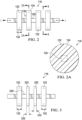
Fig. 1 shows a perspective view of a first embodiment of the invention. -
Fig. 2 shows a top view of a first embodiment of the movement member invention. -
Fig. 2A shows a section of the movement member taken alongsection lines 2A-2A ofFig. 2 -
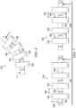
Fig. 3 shows a top view of another embodiment of the movement member. -
Fig. 4 shows a top view of another embodiment of the movement member. -
Fig. 5 shows a top view of another embodiment of the movement member. -
Fig. 6 shows a top view of the movement member ofFig. 2 . -
Fig. 7 shows another embodiment of the movement member. -
Fig. 8 is a section of the movement member taken along section line 8-8 ofFig. 2 . -
Fig. 9 is a view of other central cores of the movement member of the present invention. -
Fig. 10 is a side view of a test apparatus. -
Fig. 11 is a side view of a test apparatus. -
Fig. 12 shows another embodiment of the movement member. - Referring now to
Figs. 1-2 there is a shown a shaving razor (90) of the present invention. The shaving razor (90) comprises a handle (100) having an elongated body (102) having a proximal end (103) and an opposing distal end (104). The proximal end (103) comprises a cartridge connection mechanism (106) for connecting to a razor cartridge (110). The elongated body (102) comprises a first section (113) nearest the proximal end and a second section (114) nearest the distal end and a movement member (116) connecting the first section to the second section. The movement member (116) comprises a unitary member having a central core (120) extending along a longitudinal axis (L-L). A plurality of spaced apart projections (122) extend outward from the central core. Adjacent projections (122) are spaced apart from one another to form open slots (130) between adjacent projections. - The elongated body (102) may be provided in any shape or form and is preferably ergonomic to allow easy handling by the consumer. The elongated body may be symmetrical or asymmetrical and is preferably symmetrical in form. In one embodiment, the elongated has a curved shape. The elongated body (102) of the handle has an outer surface (105) and an interior body (107).
- The spaced apart projections (122) extend in a direction perpendicular to the longitudinal axis L-L of the central core (120). Each projection (122) has a thickness dimension (132). In the embodiment shown in
Fig. 2 each projection (122) has the same thickness dimension. In addition, each projection (122) has the same shape. Each projection (122) has an outer surface (124) remote from the central core (120). The projections (122) have a thickness dimension from 0.1 mm to 5 mm. - Referring to
Fig. 2A , the projections (122) have a circular shape when viewed along longitudinal axis L-L. The projections may have other shapes such as square, oval, rectangular and polygon. - In the embodiment of movement member (116) shown in
Fig. 3 projections (122) have the same thickness dimension (132). Projections (222) have the same thickness dimension (232). Thickness dimension (132) is greater than and different from thickness dimension (232). In addition, each projection (122) has the same shape. The thickness dimensions (132, 232) of projections (122, 222), respectively, are substantially uniform throughout the respective projection from central core (220) to their outer surfaces (124, 224). - In the embodiment of movement member (116) shown in
Fig. 4 projections (322) have a non-uniform thickness dimension (332). Near and adjacent the central core (320) the projection has its largest thickness dimension and at the outer surface (324) the projection has its smallest thickness dimension. - In the embodiment shown in
Fig. 5 , projections (422) and (472) extend outward from central core (420). Projections (422) have a different shape from projections (472). - Referring now to
Fig. 2 , the movement member (116) has three slots (130) between projections (122). The movement member (116) may include any number of slots (130) depending on the movement desired. The size of each slot (130) may be selected to achieve the desired movement of the connections member (116) during shaving. - Referring now to
Fig. 6 , there is shown the movement member (116) ofFig. 2 . Here movement member (116) is part of a razor, not shown. As the user shaves a portion of the handle is held in the user's hand represented by (H). During shaving a force is applied to the razor cartridge which translates to a force (F) being applied to one end of the movement member (116). As force (F) is applied to one end of the movement member (116) the central core (120) bends in response. During bending of the central core (120), the end surfaces (124) of projections (122) positioned away from the force (F) move closer to one another and the end surfaces (124) of the projections (122) positioned with the force (F) move away from one another. The amount of movement of central core (120) is limited by the adjacent projections coming into contact with one another preventing further movement of the central core. With larger slots (130) between adjacent projections (122) more movement can be experienced by the movement member. - Whilst not being bound by any theory it is believed that the provision of slots between projections as described herein in the movement member of the handle enables movement of the handle in at least one plane to improve skin contact of the razor cartridge with the skin.
- According to the invention, each slot (130) extends from the outer surface of handle body into the interior body of the handle toward the central core (120). The central core (120) is therefore defined by the slots (130). Having the outer surfaces (124) of projections (122) generally aligned with the outer surface of the handle allows the user to rest part of the user's hand on the movement member during shaving. This is believed to be desirable as the user can then feel the movement of the movement member (116) during shaving. The ability for the user to have tactile contact with the movement member (116) during shaving movement increases the overall confidence of the user with the shaving experience.
- In a preferred embodiment the slots (130) reduce the cross-sectional area and or volume of the movement member (116). The size, shape, volume and material for the movement member can be selected to obtain the desired movement of the movement member under typical shaving conditions.
- Referring now to
Fig. 7 , there is shown a top and side view of a movement member (116). Movement member (116) comprises projections (122) and a central core (120). According to the invention the movement member (116) also comprises slot separators (150). Slot separators (150) restrict the movement of the central core (120). As the force F1 is applied to the movement member (116) the movement of the central core (120) is restricted to a first amount by the slot separators (150). As the force F2 is applied to the movement member (116) the movement of the central core is restricted to a second amount by the slot separators (150). The force F1 is perpendicular to the force F2. The first amount of restricted movement when force F1 is applied is less than the second amount of restricted movement when force F2 is applied. Thus, when force F1 is applied the movement member (116) may move by a greater amount than when force F2 is applied to the movement member (116). Such slot separators (150) are desirable when designing the movement member to have predetermined movements amounts or limitations in a certain direction. The number, orientation, shape and dimension of the slot separators control the amount of movement for the movement member in any particular direction. - The dimensions of each slot (130), may all be the same or different. Each slot (130) may independently have a uniform cross section or may increase or decrease as they extend from the outer surface of the handle to the central core. In one preferred embodiment the slots decrease in cross section towards the central core. In some embodiments all slots have substantially identical dimensions. In some embodiments each slot has a different dimension from the next. The dimensions of the slots in addition to the number of pairs of slots and the materials of the movement member will determine the movement thereof and are selected accordingly.
- The overall shape of each slot is also determined by the outer surface contour of the handle, the shape of the projections and the shape of the central core. The slot may for example have a substantially rectangular cross-section when viewed from the side. The slot may have other shapes depending on the adjacent structures forming the slot.
- Each slot may independently have a width (136) of from 0.1mm to 2mm, preferably 0.5mm to 1.5mm, more preferably from 0.75 to 1.25mm and a depth (138) of from 0.5 mm to 5.0 mm.
- The dimensions of each of the slot separators (150) may be the same or different. The slot separators slots may have a width (152) of from 0.1 mm to 2 mm, preferably 0.5 mm to 1.5 mm, more preferably from 0.75mm to 1.25 mm.
- In one embodiment the slot width is substantially the same as a slot separator width.
- As described above the resilient movement member has a central core which extends through substantially the center of the resilient flexible portion. Referring now to
Fig. 8 , there is a shown a cross-section of movement member (116). Central core (120) has a rectangular cross-sectional shape. The central core has a width dimension (140) and a height dimension (142). The width dimension (140) is from 0.5 mm to 4.0 mm, preferably 1.0 mm to 3.0 mm, more preferably from 2.0 mm to 2.5 mm. The height dimension (142) is from 0.5 mm to 4.0 mm, preferably 1.0 mm to 3.0 mm, more preferably from 2.0 mm to 2.5 mm. Referring now toFig. 9 there is shown other cross-sectional shapes for the central core (120). The central core may have a cross-sectional shape that is triangular, square, oval, circular or other shape. - Handle body (102) and the movement member (116) may be formed from any suitable material known in the field, preferably the entire handle body (102) is formed of resilient material. Preferred materials include thermoplastics such as polypropylene, acrylonitrile butadiene styrene, high impact polystyrene, polycarbonate, polyphenylene ether/polystyrene blend; metals, or alloys such as zinc, aluminium, steel, titanium, stainless steel, brass; carbon fibre, and/ or mixtures thereof.
- The handle body (102) and movement member (116) may be formed from same material or from different material. In one embodiment the handle body (102) and the connections member (116) are formed from the same material, preferably polypropylene.
- The movement member allows the handle to flex during shaving. The flexing during shaving allows the razor cartridge to maintain contact with the user's skin during shaving providing for an improved shave as opposed to a razor having a handle that does not flex during shaving.
- Referring now to
Fig. 12 , there is shown a top and sectioned view of a movement member (116). Movement member (116) comprises projections (122) and central core (120). Movement member (116) also comprises slot separators (150). The projections (122) and slot separators may have the dimensions and shapes of those disclosed in the above-mentioned embodiments. The central core (120) is hollow having a central bore (160). The presence of the central bore (160) in the hollow central core (120) allows for increased flexibility and/or movement of the movement member (116). The central core (120) also comprises openings (162) extending from the exterior (164) of the central core (120) to the central bore (160). - A shaving razor handle and or body thereof may be manufactured using any method known in the art. Suitable methods include injection moulding and die casting and optionally 'additive or subtractive manufacturing' techniques may be used. The first section, second section and movement member may be moulded as a single unitary structure of the same material. The first section, second section and movement member may all be moulded individually as separate unitary structures and then secured together. When moulded individually the first section, second section and movement member may be moulded of the same or different materials.
- According to the invention, the razor (90) is provided with a razor cartridge (110). The razor cartridge (110) may be pivotally connected to the cartridge connecting structure (106) of the handle. The razor cartridge (110) typically comprises one or more elongated blades usually positioned between a first and second end, the one or more elongated blades comprising a tip or sharpened end extending towards the first end. The razor cartridge can include and number of blades. For example,
U.S. Patent 7,168,173 generally describes a Fusion® razor that is commercially available from The Gillette Company LLC and which includes a razor cartridge with multiple blades. Additionally, the razor cartridge may include a guard as well as a skin engaging member. A variety of razor cartridges can be used in accordance with the present invention. Non-limiting examples of suitable razor cartridges, with and without fins, guards, and/or shave aids, include those marketed by The Gillette Company LLC under the Fusion®, Venus® product lines as well as those disclosed inU.S. Patent Nos. 7,197,825 ,6,449,849 ,6,442,839 ,6,301,785 ,6,298,558 ;6,161,288 , andU.S.2008/060201 . Those of skill in the art will understand that the lubricating member can be used with any currently marketed system or disposable razor, including those having 2, 3, 4 or 5 blades. - In some embodiments, at least one lubricating member is located on the portion of the cartridge that contacts skin during the hair removal process, forward and/or aft of the blades. A feature "forward" of the one or more elongated edges, for example, is positioned so that the surface to be treated with by the hair removal device encounters the feature before it encounters the elongated edges. A feature "aft" of the elongated edge is positioned so that the surface to be treated by the hair removal device encounters the feature after it encounters the elongated edges. Where more than one lubricating member is provided on the hair removal device, they can be the same (identical) or different, in terms of physical shape/structure and/or chemical composition, and one or more of them may comprise the spray coated particulate.
- In some embodiments, a plurality (e.g. 2, a first and second) of lubricating members may be provided on the hair removal head, with the first skin engaging member comprising the same composition or different. These lubricating members may be placed collectively (for example adjacent to one another) ahead of or behind the elongated edges (e.g. blades on a razor cartridge), including side by side, or separately with one ahead of the elongated edges and the other behind.
- The lubricating member may be free standing utilizing a suitable attachment means such as adhesive or may be contained at least partially within a container.
- In some embodiments, the razor cartridge comprises a guard comprising at least one elongated flexible protrusion to engage a user's skin. The at least one flexible protrusion may comprise flexible fins generally parallel to said one or more elongated edges. The at least one flexible protrusion may additionally or alternatively comprise flexible fins comprising at least one portion which is not generally parallel to said one or more elongated edges. Non-limiting examples of suitable guards include those used in current razor blades and include those disclosed in
U.S. Patent Nos. 7,607,230 and7,024,776 ; (disclosing elastomeric / flexible fin bars);2008/0034590 (disclosing curved guard fins);2009/0049695A1 (disclosing an elastomeric guard having guard forming at least one passage extending between an upper surface and a lower surface). In some embodiments, the lubricating member is positioned on the cartridge aft of the guard and forward of the elongated edge. In another embodiment, the lubricating member is positioned on the cartridge forward of the guard. This embodiment can be particularly useful to deliver the lubricating member prior to contact with the guard. - Referring now to
Figs. 10-11 , a fixture (500) to clamp the razor (501) such that the distal end of the handle is held statically up to the mid-point of the second section of the handle. Fixture (500) should be made of suitable uncompressible material to support razor without deflection (at intended test loads) this includes metal, MDF or plastic. - A flat plate (503) that extends at least the full width of the test product is used.
- The bending Stiffness equipment is an Instron 5564 using a Static Load Cell rated to 10N.
-
- 1. Allow all test products to equilibrate at standard temperature and pressure (20°C and 1 Atm) for 1hr.
- 2. Check Load Cell is rated at 10N and in calibration. Set up control software to run a compressive test - such that the equipment will run and record the test by feeding the probe vertically downward at a rate of 3.0 mm/sec.
- 3. Determine the maximum length (L) and midpoint of the device as shown in Fig. XX. Mark the test product across it's midpoint of the second section on both front and back surfaces.
- 4. Mount the flat plate to the load cell.
- 5. Securely fix the fixture to the Instron platen.
- 6. Place the test product into the fixture such that it is clamped up to the mid-point of the test product. The fixture should orient the test product such that the slots are vertically aligned to the probe's axial axis and the probe is aligned to the razor cartridge. The mid plane of the probe should correspond to the mid plane of the razor cartridge.
- 7. Zero load readouts. Slowly lower the probe until the load readout reaches a maximum of 5gf: indicating contact. Check that the center of the probe is correctly aligned with the midpoint of the razor. Zero both load and deflection readouts.
- 8. Start the test. Record vertical deflection (mm) incrementally up to 500 grams force. Record the mean stiffness between 0.3 mm and maximum deflection.
- 9. Retract probe to the zero position.
- 10. Remove the razor from the support blocks.
- 11. Repeat steps 6-9 3 times and record the mean (and standard deviation) over these repeats.
- 12. Depending on the test product slot configuration rotate the test product through 90 degrees to measure the stiffness in all the directions of intended movement. Place the test product in the support blocks as shown in
Fig. 11 such that 50% of the test products' maximum length is unsupported, and the remainder is supported by the support blocks and allow to stabilize. - Repeat steps 6-12 until all the directions of intended movement have been measured. The stiffness of the movement member according to the above method is from 0.4N/mm-3.0N/mm.
- The dimensions and values disclosed herein are not to be understood as being strictly limited to the exact numerical values recited. Instead, unless otherwise specified, each such dimension is intended to mean both the recited value and a functionally equivalent range surrounding that value. For example, a dimension disclosed as "40 mm" is intended to mean "about 40 mm."
Claims (9)
- A shaving razor (90) comprising a handle (100) having an elongated body (102) having a proximal end (103) and an opposing distal end (104), the proximal end (103) comprising a cartridge connection mechanism (106), a razor cartridge (110) connected to the connection mechanism (106), the elongated body (102) comprising a first section (113) nearest the proximal end and a second section (114) nearest the distal end and a movement member (116) connecting the first section (113) to the second section (114), the movement member (116) comprising a unitary member having a central core (120) extending along a longitudinal axis (L-L), a plurality of spaced apart projections (122) extend outward from the central core (120) and perpendicular to the longitudinal axis (l-L) of the central core (120), adjacent projections (122) being spaced apart from one another to form open slots (130) between adjacent projections (122), characterized in that the shaving razor (90) further comprises a slot separator (150) between adjacent projections.
- The shave razor (90) of claim 1, wherein each projection (122) has a thickness dimension.
- The shaving razor (90) of claim 2, wherein the projections (122) have different thickness dimensions from one another.
- The shaving razor (90) of any one of the preceding claims, wherein each slot (130) has a slot width from 0.1 mm to 2.0 mm.
- The shaving razor (90) of any one of the preceding claims, wherein the movement member (116) has a stiffness from 0.4N/mm-3.0N/mm according to the deflection test method as defined in the patent specification.
- The shaving razor (90) of any one of the preceding claims, wherein the projections (122) have the same shape.
- The shaving razor (90) of any one of claims 1-5, wherein the projections (122) have different shapes.
- The shaving razor (90) of any one of the preceding claims, wherein the central core (120) is hollow.
- The shaving razor (90) of any one of the preceding claims, wherein the central core (120) has openings.
Applications Claiming Priority (2)
| Application Number | Priority Date | Filing Date | Title |
|---|---|---|---|
| US201862744809P | 2018-10-12 | 2018-10-12 | |
| PCT/US2019/055286 WO2020076883A1 (en) | 2018-10-12 | 2019-10-09 | Razor |
Publications (2)
| Publication Number | Publication Date |
|---|---|
| EP3863818A1 EP3863818A1 (en) | 2021-08-18 |
| EP3863818B1 true EP3863818B1 (en) | 2023-11-08 |
Family
ID=68345054
Family Applications (1)
| Application Number | Title | Priority Date | Filing Date |
|---|---|---|---|
| EP19794812.8A Active EP3863818B1 (en) | 2018-10-12 | 2019-10-09 | Razor |
Country Status (3)
| Country | Link |
|---|---|
| US (1) | US20200114535A1 (en) |
| EP (1) | EP3863818B1 (en) |
| WO (1) | WO2020076883A1 (en) |
Families Citing this family (6)
| Publication number | Priority date | Publication date | Assignee | Title |
|---|---|---|---|---|
| USD897600S1 (en) * | 2018-05-28 | 2020-09-29 | Dorco Co., Ltd. | Razor handle |
| EP3593963B1 (en) * | 2018-07-12 | 2022-08-31 | BIC Violex Single Member S.A. | Razor connectors |
| USD905343S1 (en) * | 2019-03-19 | 2020-12-15 | The Gillette Company Llc | Razor handle |
| USD905342S1 (en) * | 2019-03-19 | 2020-12-15 | The Gillette Company Llc | Razor handle |
| USD905338S1 (en) * | 2019-03-19 | 2020-12-15 | The Gillette Company Llc | Razor handle |
| USD931535S1 (en) | 2019-07-30 | 2021-09-21 | The Gillette Company Llc | Razor handle |
Family Cites Families (22)
| Publication number | Priority date | Publication date | Assignee | Title |
|---|---|---|---|---|
| JP2714462B2 (en) * | 1989-08-19 | 1998-02-16 | 松下電工株式会社 | Vibrating razor |
| US6161288A (en) | 1993-02-22 | 2000-12-19 | Andrews; Edward A. | Four blade bi-directional razor structure with flexible guard system |
| US5560106A (en) | 1993-11-09 | 1996-10-01 | Armbruster; Joseph M. | Resilient floating head razor |
| US6298558B1 (en) | 1994-10-31 | 2001-10-09 | The Gillette Company | Skin engaging member |
| US5678316A (en) | 1995-12-15 | 1997-10-21 | Warner-Lambert Company | Disposable razor |
| US5956848A (en) | 1997-02-27 | 1999-09-28 | The Gillette Company | Shaving system |
| US6301785B1 (en) | 2000-02-18 | 2001-10-16 | The Gillette Company | Shaving aid strip for razor cartridge |
| FR2805197B1 (en) * | 2000-02-22 | 2002-07-05 | Bic Soc | RAZOR HEAD COMPRISING A MOBILE BLADE HOLDER ASSEMBLY, AND RAZOR COMPRISING SUCH A HEAD |
| US6449849B1 (en) | 2000-06-29 | 2002-09-17 | Willard Hackerman | Shaving razor |
| US20040020053A1 (en) | 2000-10-16 | 2004-02-05 | The Gillette Company | Safety razors |
| US20040177519A1 (en) | 2003-03-14 | 2004-09-16 | Louis D. Tomassetti | Flexible razor and dispenser with pivoting head |
| US7272991B2 (en) | 2004-02-09 | 2007-09-25 | The Gillette Company | Shaving razors, and blade subassemblies therefor and methods of manufacture |
| US20050188539A1 (en) | 2004-02-26 | 2005-09-01 | Prudden John Jr. | Shaving blade unit |
| US7197825B2 (en) | 2004-03-11 | 2007-04-03 | The Gillette Company | Razors and shaving cartridges with guard |
| US7168173B2 (en) | 2004-03-11 | 2007-01-30 | The Gillette Company | Shaving system |
| DE202006013187U1 (en) * | 2006-08-28 | 2006-11-23 | Synpart Ag | Handle for body care appliance or cosmetic applicator has folding area with zig zag or wavy folds connected to one another at apex of folding angle |
| US20080060201A1 (en) | 2006-09-13 | 2008-03-13 | The Gillette Company | Wet shaving system including a mineral oil coated shaving aid |
| US8438736B2 (en) | 2007-08-24 | 2013-05-14 | The Gillette Company | Safety razor with improved guard |
| US20100313426A1 (en) | 2009-06-12 | 2010-12-16 | Terence Gordon Royle | Safety razor with pivot and rotation |
| US8745883B2 (en) | 2010-09-29 | 2014-06-10 | The Gillette Company | Razor handle with a rotatable portion |
| EP2508309B1 (en) | 2011-04-05 | 2016-08-03 | The Gillette Company | Razor handle with a rotatable portion |
| PL2511057T3 (en) | 2011-04-15 | 2014-08-29 | Gillette Co | Hand held device having a rotational axis |
-
2019
- 2019-10-09 EP EP19794812.8A patent/EP3863818B1/en active Active
- 2019-10-09 WO PCT/US2019/055286 patent/WO2020076883A1/en unknown
- 2019-10-14 US US16/600,955 patent/US20200114535A1/en not_active Abandoned
Also Published As
| Publication number | Publication date |
|---|---|
| US20200114535A1 (en) | 2020-04-16 |
| EP3863818A1 (en) | 2021-08-18 |
| WO2020076883A1 (en) | 2020-04-16 |
Similar Documents
| Publication | Publication Date | Title |
|---|---|---|
| EP3863818B1 (en) | Razor | |
| EP3549728B1 (en) | Shaving razor handle | |
| EP2219831B1 (en) | Razor with rearwardly secured shaving blade member | |
| EP1722944B1 (en) | Razors and shaving cartridges with guard | |
| EP1722938B1 (en) | Shaving system | |
| EP1722939B1 (en) | Shaving cartridges and razors | |
| EP4177019A1 (en) | Shaving razor cartridge | |
| EP1722937B1 (en) | Shaving razors and shaving cartridges | |
| EP3513921B1 (en) | Razor cartridge | |
| US8984756B2 (en) | Shaving system | |
| US8024863B2 (en) | Conforming wet shaving razor | |
| WO2015142663A1 (en) | Metal spring return | |
| WO2016153798A1 (en) | Shaving razor cartridge | |
| EP2823941A1 (en) | Razor cartridges | |
| WO2009057071A1 (en) | Conforming wet shaving razor | |
| EP2219832B1 (en) | Razor with floatably secured shaving blade member | |
| JP2024510214A (en) | razor cartridge |
Legal Events
| Date | Code | Title | Description |
|---|---|---|---|
| STAA | Information on the status of an ep patent application or granted ep patent |
Free format text: STATUS: UNKNOWN |
|
| STAA | Information on the status of an ep patent application or granted ep patent |
Free format text: STATUS: THE INTERNATIONAL PUBLICATION HAS BEEN MADE |
|
| PUAI | Public reference made under article 153(3) epc to a published international application that has entered the european phase |
Free format text: ORIGINAL CODE: 0009012 |
|
| STAA | Information on the status of an ep patent application or granted ep patent |
Free format text: STATUS: REQUEST FOR EXAMINATION WAS MADE |
|
| 17P | Request for examination filed |
Effective date: 20210322 |
|
| AK | Designated contracting states |
Kind code of ref document: A1 Designated state(s): AL AT BE BG CH CY CZ DE DK EE ES FI FR GB GR HR HU IE IS IT LI LT LU LV MC MK MT NL NO PL PT RO RS SE SI SK SM TR |
|
| DAV | Request for validation of the european patent (deleted) | ||
| DAX | Request for extension of the european patent (deleted) | ||
| GRAP | Despatch of communication of intention to grant a patent |
Free format text: ORIGINAL CODE: EPIDOSNIGR1 |
|
| STAA | Information on the status of an ep patent application or granted ep patent |
Free format text: STATUS: GRANT OF PATENT IS INTENDED |
|
| P01 | Opt-out of the competence of the unified patent court (upc) registered |
Effective date: 20230430 |
|
| INTG | Intention to grant announced |
Effective date: 20230612 |
|
| GRAS | Grant fee paid |
Free format text: ORIGINAL CODE: EPIDOSNIGR3 |
|
| GRAA | (expected) grant |
Free format text: ORIGINAL CODE: 0009210 |
|
| STAA | Information on the status of an ep patent application or granted ep patent |
Free format text: STATUS: THE PATENT HAS BEEN GRANTED |
|
| AK | Designated contracting states |
Kind code of ref document: B1 Designated state(s): AL AT BE BG CH CY CZ DE DK EE ES FI FR GB GR HR HU IE IS IT LI LT LU LV MC MK MT NL NO PL PT RO RS SE SI SK SM TR |
|
| REG | Reference to a national code |
Ref country code: GB Ref legal event code: FG4D |
|
| REG | Reference to a national code |
Ref country code: CH Ref legal event code: EP |
|
| REG | Reference to a national code |
Ref country code: DE Ref legal event code: R096 Ref document number: 602019041148 Country of ref document: DE |
|
| REG | Reference to a national code |
Ref country code: IE Ref legal event code: FG4D |
|
| REG | Reference to a national code |
Ref country code: LT Ref legal event code: MG9D |
|
| REG | Reference to a national code |
Ref country code: NL Ref legal event code: MP Effective date: 20231108 |
|
| PG25 | Lapsed in a contracting state [announced via postgrant information from national office to epo] |
Ref country code: GR Free format text: LAPSE BECAUSE OF FAILURE TO SUBMIT A TRANSLATION OF THE DESCRIPTION OR TO PAY THE FEE WITHIN THE PRESCRIBED TIME-LIMIT Effective date: 20240209 |
|
| PG25 | Lapsed in a contracting state [announced via postgrant information from national office to epo] |
Ref country code: IS Free format text: LAPSE BECAUSE OF FAILURE TO SUBMIT A TRANSLATION OF THE DESCRIPTION OR TO PAY THE FEE WITHIN THE PRESCRIBED TIME-LIMIT Effective date: 20240308 |