EP3593581B1 - Configuration à faible latence à haute fiabilité pour systèmes de communication sans fil - Google Patents
Configuration à faible latence à haute fiabilité pour systèmes de communication sans fil Download PDFInfo
- Publication number
- EP3593581B1 EP3593581B1 EP18714407.6A EP18714407A EP3593581B1 EP 3593581 B1 EP3593581 B1 EP 3593581B1 EP 18714407 A EP18714407 A EP 18714407A EP 3593581 B1 EP3593581 B1 EP 3593581B1
- Authority
- EP
- European Patent Office
- Prior art keywords
- wireless service
- wireless
- message
- resources
- error rate
- Prior art date
- Legal status (The legal status is an assumption and is not a legal conclusion. Google has not performed a legal analysis and makes no representation as to the accuracy of the status listed.)
- Active
Links
- 238000004891 communication Methods 0.000 title claims description 172
- 230000006854 communication Effects 0.000 title claims description 172
- 238000000034 method Methods 0.000 claims description 77
- 230000005540 biological transmission Effects 0.000 claims description 71
- 230000011664 signaling Effects 0.000 claims description 30
- 238000004590 computer program Methods 0.000 claims description 3
- 208000037918 transfusion-transmitted disease Diseases 0.000 claims 12
- 101000741965 Homo sapiens Inactive tyrosine-protein kinase PRAG1 Proteins 0.000 claims 2
- 102100038659 Inactive tyrosine-protein kinase PRAG1 Human genes 0.000 claims 2
- 230000002776 aggregation Effects 0.000 description 37
- 238000004220 aggregation Methods 0.000 description 37
- 230000006870 function Effects 0.000 description 29
- 238000010586 diagram Methods 0.000 description 15
- 238000005516 engineering process Methods 0.000 description 15
- 239000000969 carrier Substances 0.000 description 9
- 230000008569 process Effects 0.000 description 7
- 238000013468 resource allocation Methods 0.000 description 7
- 230000002093 peripheral effect Effects 0.000 description 4
- 230000004044 response Effects 0.000 description 4
- 230000001360 synchronised effect Effects 0.000 description 4
- 230000008713 feedback mechanism Effects 0.000 description 3
- 230000003287 optical effect Effects 0.000 description 3
- 238000001228 spectrum Methods 0.000 description 3
- 230000003044 adaptive effect Effects 0.000 description 2
- 230000008901 benefit Effects 0.000 description 2
- 238000012937 correction Methods 0.000 description 2
- 125000004122 cyclic group Chemical group 0.000 description 2
- 230000001934 delay Effects 0.000 description 2
- 239000000835 fiber Substances 0.000 description 2
- 230000003993 interaction Effects 0.000 description 2
- 230000008520 organization Effects 0.000 description 2
- 239000002245 particle Substances 0.000 description 2
- 238000012545 processing Methods 0.000 description 2
- 230000002441 reversible effect Effects 0.000 description 2
- 238000012546 transfer Methods 0.000 description 2
- 241001071864 Lethrinus laticaudis Species 0.000 description 1
- 241000700159 Rattus Species 0.000 description 1
- 238000013475 authorization Methods 0.000 description 1
- 230000007175 bidirectional communication Effects 0.000 description 1
- 230000001413 cellular effect Effects 0.000 description 1
- 230000008859 change Effects 0.000 description 1
- 239000003795 chemical substances by application Substances 0.000 description 1
- 230000000295 complement effect Effects 0.000 description 1
- 230000001419 dependent effect Effects 0.000 description 1
- 238000001514 detection method Methods 0.000 description 1
- 230000004069 differentiation Effects 0.000 description 1
- 230000006872 improvement Effects 0.000 description 1
- 230000007774 longterm Effects 0.000 description 1
- 238000012423 maintenance Methods 0.000 description 1
- 239000011159 matrix material Substances 0.000 description 1
- 238000005259 measurement Methods 0.000 description 1
- 230000000116 mitigating effect Effects 0.000 description 1
- 238000010295 mobile communication Methods 0.000 description 1
- 238000012544 monitoring process Methods 0.000 description 1
- 238000012913 prioritisation Methods 0.000 description 1
- 230000011218 segmentation Effects 0.000 description 1
- 230000003595 spectral effect Effects 0.000 description 1
- 230000008685 targeting Effects 0.000 description 1
- 230000001960 triggered effect Effects 0.000 description 1
Images


Classifications
-
- H—ELECTRICITY
- H04—ELECTRIC COMMUNICATION TECHNIQUE
- H04L—TRANSMISSION OF DIGITAL INFORMATION, e.g. TELEGRAPHIC COMMUNICATION
- H04L41/00—Arrangements for maintenance, administration or management of data switching networks, e.g. of packet switching networks
- H04L41/08—Configuration management of networks or network elements
- H04L41/0803—Configuration setting
- H04L41/0823—Configuration setting characterised by the purposes of a change of settings, e.g. optimising configuration for enhancing reliability
- H04L41/0836—Configuration setting characterised by the purposes of a change of settings, e.g. optimising configuration for enhancing reliability to enhance reliability, e.g. reduce downtime
-
- H—ELECTRICITY
- H04—ELECTRIC COMMUNICATION TECHNIQUE
- H04L—TRANSMISSION OF DIGITAL INFORMATION, e.g. TELEGRAPHIC COMMUNICATION
- H04L1/00—Arrangements for detecting or preventing errors in the information received
- H04L1/0001—Systems modifying transmission characteristics according to link quality, e.g. power backoff
- H04L1/0023—Systems modifying transmission characteristics according to link quality, e.g. power backoff characterised by the signalling
- H04L1/0026—Transmission of channel quality indication
-
- H—ELECTRICITY
- H04—ELECTRIC COMMUNICATION TECHNIQUE
- H04L—TRANSMISSION OF DIGITAL INFORMATION, e.g. TELEGRAPHIC COMMUNICATION
- H04L1/00—Arrangements for detecting or preventing errors in the information received
- H04L1/0001—Systems modifying transmission characteristics according to link quality, e.g. power backoff
- H04L1/0023—Systems modifying transmission characteristics according to link quality, e.g. power backoff characterised by the signalling
- H04L1/0028—Formatting
- H04L1/0031—Multiple signaling transmission
-
- H—ELECTRICITY
- H04—ELECTRIC COMMUNICATION TECHNIQUE
- H04L—TRANSMISSION OF DIGITAL INFORMATION, e.g. TELEGRAPHIC COMMUNICATION
- H04L1/00—Arrangements for detecting or preventing errors in the information received
- H04L1/12—Arrangements for detecting or preventing errors in the information received by using return channel
- H04L1/16—Arrangements for detecting or preventing errors in the information received by using return channel in which the return channel carries supervisory signals, e.g. repetition request signals
- H04L1/18—Automatic repetition systems, e.g. Van Duuren systems
- H04L1/1812—Hybrid protocols; Hybrid automatic repeat request [HARQ]
-
- H—ELECTRICITY
- H04—ELECTRIC COMMUNICATION TECHNIQUE
- H04L—TRANSMISSION OF DIGITAL INFORMATION, e.g. TELEGRAPHIC COMMUNICATION
- H04L5/00—Arrangements affording multiple use of the transmission path
- H04L5/003—Arrangements for allocating sub-channels of the transmission path
- H04L5/0053—Allocation of signaling, i.e. of overhead other than pilot signals
- H04L5/0055—Physical resource allocation for ACK/NACK
-
- H—ELECTRICITY
- H04—ELECTRIC COMMUNICATION TECHNIQUE
- H04W—WIRELESS COMMUNICATION NETWORKS
- H04W24/00—Supervisory, monitoring or testing arrangements
- H04W24/02—Arrangements for optimising operational condition
-
- H—ELECTRICITY
- H04—ELECTRIC COMMUNICATION TECHNIQUE
- H04W—WIRELESS COMMUNICATION NETWORKS
- H04W52/00—Power management, e.g. TPC [Transmission Power Control], power saving or power classes
- H04W52/04—TPC
- H04W52/18—TPC being performed according to specific parameters
-
- H—ELECTRICITY
- H04—ELECTRIC COMMUNICATION TECHNIQUE
- H04W—WIRELESS COMMUNICATION NETWORKS
- H04W72/00—Local resource management
- H04W72/04—Wireless resource allocation
- H04W72/044—Wireless resource allocation based on the type of the allocated resource
-
- H—ELECTRICITY
- H04—ELECTRIC COMMUNICATION TECHNIQUE
- H04W—WIRELESS COMMUNICATION NETWORKS
- H04W72/00—Local resource management
- H04W72/12—Wireless traffic scheduling
-
- H—ELECTRICITY
- H04—ELECTRIC COMMUNICATION TECHNIQUE
- H04W—WIRELESS COMMUNICATION NETWORKS
- H04W72/00—Local resource management
- H04W72/20—Control channels or signalling for resource management
-
- H—ELECTRICITY
- H04—ELECTRIC COMMUNICATION TECHNIQUE
- H04W—WIRELESS COMMUNICATION NETWORKS
- H04W72/00—Local resource management
- H04W72/50—Allocation or scheduling criteria for wireless resources
- H04W72/54—Allocation or scheduling criteria for wireless resources based on quality criteria
-
- H—ELECTRICITY
- H04—ELECTRIC COMMUNICATION TECHNIQUE
- H04W—WIRELESS COMMUNICATION NETWORKS
- H04W76/00—Connection management
- H04W76/20—Manipulation of established connections
- H04W76/27—Transitions between radio resource control [RRC] states
-
- H—ELECTRICITY
- H04—ELECTRIC COMMUNICATION TECHNIQUE
- H04L—TRANSMISSION OF DIGITAL INFORMATION, e.g. TELEGRAPHIC COMMUNICATION
- H04L5/00—Arrangements affording multiple use of the transmission path
- H04L5/003—Arrangements for allocating sub-channels of the transmission path
- H04L5/0044—Arrangements for allocating sub-channels of the transmission path allocation of payload
-
- H—ELECTRICITY
- H04—ELECTRIC COMMUNICATION TECHNIQUE
- H04W—WIRELESS COMMUNICATION NETWORKS
- H04W52/00—Power management, e.g. TPC [Transmission Power Control], power saving or power classes
- H04W52/04—TPC
- H04W52/06—TPC algorithms
- H04W52/08—Closed loop power control
-
- H—ELECTRICITY
- H04—ELECTRIC COMMUNICATION TECHNIQUE
- H04W—WIRELESS COMMUNICATION NETWORKS
- H04W52/00—Power management, e.g. TPC [Transmission Power Control], power saving or power classes
- H04W52/04—TPC
- H04W52/06—TPC algorithms
- H04W52/10—Open loop power control
Definitions
- the present disclosure for example, relates to wireless communication systems and more particularly to high reliability low latency configuration for wireless communications systems.
- LTE Long Term Evolution
- SC-FDMA single-carrier frequency division multiple access
- MIMO multiple-input multiple-output
- a wireless multiple-access communication system may include a number of base stations, each simultaneously supporting communication for multiple communication devices, otherwise known as user equipment (UEs).
- UEs user equipment
- a set of one or more base stations may define an eNodeB (eNB).
- eNB eNodeB
- a wireless multiple access communication system may include a number of smart radio heads (RHs) in communication with a number of access node controllers (ANCs), where a set of one or more RHs, in communication with an ANC, defines a base station (e.g., an eNB or gNB).
- RHs smart radio heads
- ANCs access node controllers
- a base station may communicate with a set of UEs on downlink (DL) channels (e.g., for transmissions from a base station to a UE) and uplink (UL) channels (e.g., for transmissions from a UE to a base station).
- DL downlink
- UL uplink
- EP 2 244 433 A1 relates to the definition of a structure of a sub-frame for transmission from a Node B to at least one relay node in a communication system. Furthermore, it relates to the operation of Node B and relay node regarding the generation, transmission and reception of such special sub-frame format and is inter alia applicable to a 3GPP LTE-A system as standardized by the 3 rd Generation Partnership Project (3GPP). It further suggests a new structure for a sub-frame that is capable of conveying control information for a relay node to the relay node essentially independent from propagation delays.
- the structure of the sub-frame takes into account propagation delays of the radio signal from Node B to relay node, in that control information for a relay node is transmitted from the Node B on OFDM symbols that can be expected to be received by the relay node.
- WO 2016/143968 A1 relates to a method and a device for reducing a transmission resource of a control channel in a short TTI in a wireless communication system. Specifically, a plurality of first downlink channels which are received during an sTTI and are included in a subframe corresponding to one TTI, and a second downlink channel received during a TTI are received. Further, information on a resource block used for the plurality of first downlink channels is obtained by using a resource block indicator transmitted to a downlink control channel of a control region comprising the first symbol of a subframe. The plurality of first downlink channels are demodulated by using the information, and the second downlink channel is demodulated by using the downlink control channel.
- Different UEs within a multiple-access communications system may have varying standards from one another based on particular applications or deployments. Systems may therefore need to support multiple wireless communication services. But because of the mobile nature of some UEs and the dynamic character of mobile originated and mobile terminated data, the system may need to dynamically change the wireless communication service for a given UE. Reliance and resource configurations or legacy feedback mechanisms, for example, may limit the system's ability to meet such needs.
- Some wireless communication systems may be operable to support several wireless communications service types using various enhancements to resource configurations, feedback mechanisms, and the like.
- a system may, for example, support a service type associated with communications having high reliability and low latency.
- HRLLCs high reliability, low latency communications
- HRLLCs may be configured to coexist with other service types with different (e.g., more relaxed) latency and reliability constraints.
- Considerations for such systems may include configuration of HRLLC, DL control enhancements, UL control enhancements, channel state information (CSI) enhancements, physical uplink shared channel (PUSCH) enhancements, UL power control enhancements, and backhaul handling.
- CSI channel state information
- PUSCH physical uplink shared channel
- UL power control enhancements UL power control enhancements
- backhaul handling Various methods, systems, and apparatuses are described herein that support high reliability, low latency configurations.
- Wireless communications systems as described herein may be configured to support a plurality of service types with different latency, reliability, or throughput rates or standards.
- One such service type may be referred to herein as high reliability, low latency communication (HRLLC).
- HRLLC high reliability, low latency communication
- Various techniques described may be employed to improve HRLLC performance while supporting coexistence with legacy service types or other service types that may be supported by the wireless communications system.
- the described techniques may be employed for HRLLC enhancements, downlink and uplink control enhancements, channel state information (CSI) feedback enhancements, physical uplink shared channel (PUSCH) enhancements, and UL power control enhancements.
- CSI channel state information
- PUSCH physical uplink shared channel
- a base station in some LTE or NR deployments may transmit to one or more UEs using reduced scheduling timing to meet various latency and reliability standards.
- a base station may allocate transmission resources to a UE that may include time resources and frequency resources.
- reliability for low latency services may be enhanced through feedback mechanisms that may provide for retransmission of unsuccessfully received transmissions, such as according to hybrid acknowledgment repeat request (HARQ) feedback techniques, for example.
- HARQ hybrid acknowledgment repeat request
- the various enhancements described herein may increase the efficiency and reliability of a wireless communications system.
- FIG. 1 illustrates an example of a wireless communications system 100 in accordance with various aspects of the disclosure.
- the wireless communications system 100 includes base stations 105, user equipment (UEs) 115, and a core network 130.
- System 100 may be configured to provide multiple wireless communication services, including, for example high reliability low latency communications.
- the core network 130 may provide user authentication, access authorization, tracking, Internet Protocol (IP) connectivity, and other access, routing, or mobility functions.
- the base stations 105 interface with the core network 130 through backhaul links 132 (e.g., S1, etc.) and may perform radio configuration and scheduling for communication with the UEs 115, or may operate under the control of a base station controller.
- the base stations 105 may communicate, either directly or indirectly (e.g., through core network 130), with each other over backhaul links 134 (e.g., X1, etc.), which may be wired or wireless communication links.
- the base stations 105 may wirelessly communicate with the UEs 115 via one or more base station antennas. Each of the base station 105 sites may provide communication coverage for a respective geographic coverage area 110.
- base stations 105 may be referred to as a base transceiver station, a radio base station, an access point, a radio transceiver, a NodeB, evolved NodeB (eNB), Home NodeB, a Home eNodeB, a next generation nodeB (gNB), or some other suitable terminology.
- the geographic coverage area 110 for a base station 105 may be divided into sectors making up only a portion of the coverage area.
- the wireless communications system 100 may include base stations 105 of different types (e.g., macro and/or small cell base stations). There may be overlapping geographic coverage areas 110 for different technologies.
- Base station 105 may support multiple wireless communication services on one or more cells. Base stations 105 may, for example, be configured for high reliability, low latency communications in addition to other mobile broadband, broadcast, and or other services
- the communication networks may be packet-based networks that operate according to a layered protocol stack.
- communications at the bearer or Packet Data Convergence Protocol (PDCP) layer may be IP-based.
- a Radio Link Control (RLC) layer may perform packet segmentation and reassembly to communicate over logical channels.
- RLC Radio Link Control
- a Medium Access Control (MAC) layer may perform priority handling and multiplexing of logical channels into transport channels.
- the MAC layer may also use Hybrid Automatic Repeat Request (HARQ) to provide retransmission at the MAC layer to improve link efficiency.
- HARQ enables the overhead of error correction to be adapted dynamically depending on the channel quality.
- FEC forward error correction
- HARQ is a method of ensuring that data is received correctly over a wireless communication link 125.
- HARQ may include a combination of error detection (e.g., using a cyclic redundancy check (CRC)), FEC, and retransmission (e.g., automatic repeat request (ARQ)) and may improve throughput at the MAC layer in poor radio conditions.
- CRC cyclic redundancy check
- ARQ automatic repeat request
- Incremental Redundancy HARQ incorrectly received data may be stored in a buffer and combined with subsequent transmissions to improve the overall likelihood of successfully decoding the data.
- redundancy bits are added to each message prior to transmission. This may be useful in poor conditions.
- redundancy bits are not added to each transmission, but are retransmitted after the transmitter of the original message receives a negative acknowledgement (NACK) indicating a failed attempt to decode the information.
- NACK negative acknowledgement
- the chain of transmission, response and retransmission may be referred to as a HARQ process.
- a limited number of HARQ processes may be used for a given communication link 125
- the Radio Resource Control (RRC) protocol layer may provide establishment, configuration, and maintenance of an RRC connection between a UE 115 and the base stations 105 or core network 130 supporting radio bearers for the user plane data.
- RRC Radio Resource Control
- the transport channels may be mapped to physical channels.
- Different wireless communication services may be configured or activated by RRC or PHY layer signaling in various examples.
- a UE 115 may be configured for URLLC using RRC signaling, and the UE 115 may be assigned time-frequency resources for URLLC using PHY layer control signaling.
- the UEs 115 are dispersed throughout the wireless communications system 100, and each UE 115 may be stationary or mobile.
- a LTE 115 may also include or be referred to by those skilled in the art as a mobile station, a subscriber station, a mobile unit, a subscriber unit, a wireless unit, a remote unit, a mobile device, a wireless device, a wireless communications device, a remote device, a mobile subscriber station, an access terminal, a mobile terminal, a wireless terminal, a remote terminal, a handset, a user agent, a mobile client, a client, or some other suitable terminology.
- a UE 115 may be a cellular phone, a personal digital assistant (PDA), a wireless modem, a wireless communication device, a handheld device, a tablet computer, a laptop computer, a cordless phone, a wireless local loop (WLL) station, or the like.
- PDA personal digital assistant
- a UE 115 may be able to communicate with various types of base stations 105 and network equipment including macro eNBs, small cell eNBs, relay base stations, and the like.
- the communication links 125 shown in wireless communications system 100 may include uplink (UL) transmissions from a UE 115 to a base station 105, and/or downlink (DL) transmissions, from a base station 105 to a UE 115.
- the downlink transmissions may also be called forward link transmissions while the uplink transmissions may also be called reverse link transmissions.
- Each communication link 125 may include one or more carriers, where each carrier may be a signal made up of multiple sub-carriers (e.g., waveform signals of different frequencies) modulated according to the various radio technologies described above. Each modulated signal may be sent on a different sub-carrier and may carry control information (e.g., reference signals, control channels, etc.), overhead information, user data, etc.
- Communication links 125 may represent various wireless communication services, such as URLLC.
- the communication links 125 may transmit bidirectional communications using frequency division duplexing (FDD) (e.g., using paired spectrum resources) or time division duplexing (TDD) operation (e.g., using unpaired spectrum resources).
- FDD frequency division duplexing
- TDD time division duplexing
- base stations 105 and/or UEs 115 may include multiple antennas for employing antenna diversity schemes to improve communication quality and reliability between base stations 105 and UEs 115. Additionally or alternatively, base stations 105 and/or UEs 115 may employ multiple-input, multiple-output (MIMO) techniques that may take advantage of multi-path environments to transmit multiple spatial layers carrying the same or different coded data.
- MIMO multiple-input, multiple-output
- Wireless communications system 100 may support operation on multiple cells or carriers, a feature which may be referred to as carrier aggregation (CA) or multi-carrier operation.
- a carrier may also be referred to as a component carrier (CC), a layer, a channel, etc.
- CC component carrier
- the terms “carrier,” “component carrier,” “cell,” and “channel” may be used interchangeably herein.
- a UE 115 may be configured with multiple downlink CCs and one or more uplink CCs for carrier aggregation.
- Carrier aggregation may be used with both FDD and TDD component carriers.
- wireless communication system 100 may support communications with high reliability and low latency.
- ultra-reliable, low latency communication URLLC
- URLLCs may target a reliability of 10 ⁇ -5 within a 1-ms transmission time interval (TTI).
- TTI transmission time interval
- the reliability may refer to a bit error rate or some other suitable metric (e.g., such that the probability that a given bit may be decoded correctly is 1 - 10 ⁇ -5).
- Such communications may be associated with an ultra-reliable low-latency communication channel (URLCC).
- URLCC ultra-reliable low-latency communication channel
- URLCC may be enabled for both 1-ms TTIs and shortened TTIs (sTTIs). That is, some systems (e.g., which may be referred to as legacy systems) may support only 1-ms based TTIs with at least 4-ms HARQ/scheduling timing. Such scheduling timing may be referred to in aspects of the present disclosure as 'n+4' timing. However, some such systems may be modified to introduce sTTIs (e.g., to reduce latency) along with modified 1-ms TTIs (e.g., with reduced timing).
- sTTIs e.g., to reduce latency
- some such systems may support a 1-ms TTI with 3-ms HARQ/scheduling timing (e.g., which may be referred to as 'n+3' timing herein), 2-symbol sTTI for FDD (e.g., for FS type 1), 1-slot sTTI for FDD and TDD (e.g., for FS type 2), and other duration TTIs no sTTIs for FS type 3.
- 2-symbol sTTI for FDD e.g., for FS type 1
- 1-slot sTTI for FDD and TDD e.g., for FS type 2
- the 1-ms based TTI may be further enhanced (e.g., to support high reliability, low latency communications (HRLLC)).
- HRLLCs may be examples of URLLCs.
- HRLLCs may have relaxed latency and/or reliability standards compared to URLLCs, though both may offer improved latency and reliability compared to other (e.g., conventional) communications.
- the enhancements may enable a base station 105 to have some flexibility in targeting the performance metrics. That is, the base station 105 may manage the desired reliability under a certain delay constraint.
- UEs 115 operating in a connected mode or RRC connected mode (e.g., RRC_CONNECTED UEs 115), though UEs 115 operating in an idle mode or RRC idle mode UEs 115 (e.g., RRC_IDLE UEs 115) are also considered, and those skilled in the art will recognize the applicability to both RRC_CONNECTED and RRC_IDLE UEs 115.
- Techniques described herein consider configuration of HRLLC, DL control enhancements, UL control enhancements, channel state information (CSI) enhancements, physical uplink shared channel (PUSCH) enhancements, UL power control enhancements, and backhaul handling.
- CSI channel state information
- PUSCH physical uplink shared channel
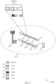
- FIG. 2 illustrates an example of a wireless communications system 200 that supports high reliability low latency configuration in accordance with various aspects of the present disclosure.
- Wireless communications system 200 includes base station 105-a and UE 115-a, which may be examples of aspects of the corresponding devices as described above with reference to FIG. 1 .
- the wireless communications system 200 may operate according to a radio access technology (RAT) such as a LTE, 5G, or NR RAT, although techniques described herein may be applied to any RAT and to systems that may concurrently use two or more different RATs.
- RAT radio access technology
- Base station 105-a may communicate with UE 115-a over an uplink carrier 205 and a downlink carrier 215.
- base station 105-a may allocate resources for communication with UEs over uplink carrier 205 and downlink carrier 215.
- base station 105-a may allocate uplink subframes 210 in uplink carrier 205 for uplink transmissions from UE 115-a, and one or more uplink subframes 210 may correspond to a legacy LTE TTI of 1 ms.
- uplink subframes 210 may include a first uplink subframe 210-a, a second uplink subframe 210-b, and a third uplink subframe 210-c.
- Each of the uplink subframes 210 may include two slots, in which each slot may have seven OFDM symbols for a normal cyclic prefix.
- a first slot (slot 0) 225 and a second slot (slot 1) 230 may be included in the first subframe 210-a.
- Shortened TTIs may be included or coincide with a slot; sTTIs may include several sTTIs, like sTTI-0 235, sTTI-1 240..., sTTI- n 245.
- TTI lengths may be used for transmissions over uplink carrier 205 and/or downlink carrier 215.
- two-symbol sTTI and 1-slot sTTI durations may be supported for physical uplink control channel (PUCCH) and physical uplink shared channel (PUSCH) transmissions (or shortened PUCCH (sPUCCH) and shortened PUSCH (sPUSCH) transmissions).
- PUCCH physical uplink control channel
- PUSCH physical uplink shared channel
- sPUSCH shortened PUCCH
- sPUSCH shortened PUSCH
- UE 115-a may be semi-statically configured (e.g., and/or dynamically triggered) with HRLLC while still maintaining legacy 1-ms TTI based communications.
- the possible combinations of 1-ms based TTI for a UE 115 may include 1-ms TTI with n+4 timing, 1-ms TTI with n+4 timing and n+3 timing without HRLLC, 1-ms TTI with n+4 timing and n+3 timing with HRLLC, and 1-ms TTI with n+4 timing and n+3 timing with and without HRLLC.
- Such timing may be referred to as scheduling timing, as discussed above, and may relate to the number of TTIs or sTTIs between a downlink transmission (e.g., PDCCH, PUSCH, etc.) and a responsive uplink transmission (e.g., PUCCH, PUSCH, etc.). Or the timing may relate to an uplink transmission and a responsive downlink transmission (e.g., PDSCH, retransmission, etc.).
- a downlink transmission e.g., PDCCH, PUSCH, etc.
- a responsive uplink transmission e.g., PUCCH, PUSCH, etc.
- the timing may relate to an uplink transmission and a responsive downlink transmission (e.g., PDSCH, retransmission, etc.).
- the differentiation of HRLLC as compared to regular communications may be explicitly indicated.
- a different radio network temporary identifier (RNTI) may be used for HRLLC, different downlink control information (DCI) formats, different control decoding candidates (which may also be called search candidates), some indication (e.g., implicit or explicit) in DCI, semi-static configuration (e.g., via RRC signaling), etc.
- RNTI radio network temporary identifier
- DCI downlink control information
- search candidates which may also be called search candidates
- some indication e.g., implicit or explicit
- semi-static configuration e.g., via RRC signaling
- TTI configurations and HARQ timing may be configured to provide for an initial transmission and a retransmission of the initial transmission within a low latency timing interval (e.g., 1-ms).
- a low latency timing interval e.g., 1-ms
- FIG. 3 illustrates an example of uplink and downlink TTIs 300 in accordance with various aspects of the present disclosure.
- Uplink and downlink TTIs 300 may be used for communications between a UE 115 and a base station 105 such as discussed above with reference to FIGs. 1 and 2 .
- downlink TTIs 305 may be used for downlink transmissions from a base station 105 to a UE 115.
- uplink TTIs 310 may be used for uplink transmissions from a UE 115 to a base station 105.
- Uplink and downlink TTIs 300 illustrate aspects of n+4 timing and n+3 timing, as described above. As illustrated, uplink and downlink TTIs 300 each contain two slots.
- a first downlink TTI 320 may be transmitted to a UE 115, and the UE 115 may attempt to demodulate and decode the transmission and generate an ACK/NACK indication 325 that may be transmitted in uplink TTI 330, which may be a first uplink TTI that starts at or after n + 3 TTIs after the first downlink TTI 320.
- the base station may format a rescheduling and retransmission 335 to the UE, which may be transmitted in a first downlink TTI that starts at or after n+3 TTIs after the ACK/NACK indication 325, which in this example is downlink TTI-6 355.
- ACK/NACK feedback for downlink TTI-1 may be transmitted in uplink TTI-4 345
- ACK/NACK feedback for downlink TTI-2 may be transmitted in uplink TTI-5, and so on.
- a first downlink TTI 320 may be transmitted to a UE 115, and the UE 115 may attempt to demodulate and decode the transmission and generate an ACK/NACK indication 340 that may be transmitted in uplink TTI-4 345, which may be a first uplink TTI that starts at or after n + 4 TTIs after the first downlink TTI 320.
- the base station may format a rescheduling and retransmission 350 to the UE, which may be transmitted in a first downlink TTI that starts at or after n+4 TTIs after the ACK/NACK indication 340, which in this example is downlink TTI-8 360.
- ACK/NACK feedback for downlink TTI-1 may be transmitted in uplink TTI-5
- ACK/NACK feedback for downlink TTI-2 may be transmitted in uplink TTI-6, and so on.
- HARQ feedback timing may be reduced when using n+3 timing relative to n+4 timing.
- HARQ feedback using an n +4 timing may not provide targeted reliability and latency.
- the configuration of the HRLLC may only be applicable to n+3 timing.
- the applicability of the configuration may depend on the maximum timing advance (TA) 315 and/or transport block size (TBS) limitations for n+3 communications.
- TA 315 may refer to the amount of time that a UE 115 begins transmitting its uplink frames before the arrival of the corresponding downlink frames. In some examples, TA 315 may vary between n+3 timing and n+4 timing.
- HRLLC configuration may additionally or alternatively be applicable for n+4 timing.
- HRLLC configuration may additionally or alternatively be applicable for n+4 timing.
- FIG. 4 illustrates an example control channel configuration 400 in accordance with various aspects of the present disclosure.
- Control configuration 400 may support enhanced physical downlink control channel (PDCCH) operation with various aggregation levels.
- PDCCH physical downlink control channel
- higher aggregation levels for DL control channels when HRLLC is configured e.g., semi-statically
- UESS UE-specific search space
- some systems e.g., legacy systems
- CCEs control channel elements
- the supported aggregation levels for one or both of these channels may be extended to include higher aggregation levels (e.g., 16, 32, etc.). Higher aggregation levels may provide for more reliable control channel information, e.g., which may be important for HRLLC.
- Control channel configuration 400 may be divided into CCEs 405, each of which may span a plurality of REGs. As illustrated in FIG. 4 , control channel configuration 400 contains 48 CCEs 405 (i.e., 24 in a respective time periods 410, 415). In some examples, the number of time periods may be dynamically indicated by the physical control format indicator channel (PCFICH). In some cases, time period 410 may represent a first OFDM symbol period and time period 415 may represent a second OFDM symbol period. It is to be understood that the illustrations are for example purposes only, and that aggregation configuration 400 may contain any suitable number of CCEs 405.
- PCFICH physical control format indicator channel
- legacy systems may support one, two, four, or eight CCEs 405 being aggregated to form a search candidate 420, 425, 430, or 435, respectively (e.g., for PDCCH or ePDCCH).
- PDCCH and/or ePDCCH may be configured to support higher aggregation levels.
- aggregation configuration 400 may additionally support one or more search candidates 440 containing 16 CCEs 405. Even higher aggregation (e.g., 32 CCEs 405) may be achievable in accordance with techniques described herein.
- each CCE may contain e.g., nine resource element groups (REGs).
- REGs resource element groups
- these REGs may be logically continuous, but may be mapped in a distributed manner within the aggregation configuration 400.
- the 9 REGs may not span tones 0 through 35; rather, a given CCE might be on tones 0, 1, 2, 3, 32, 33, 34, 35, 60, 61, 62, 63, etc. That is, the tones may not be contiguous.
- the aggregation configuration 400 may have 6/6/2/2 decoding candidates for aggregation levels 1/2/4/8, respectively. That is, a UE 115 may attempt blind decodes for six search candidates 420, six search candidates 425, two search candidates 430, and two search candidates 435 in search of PDCCH. In some cases, one or more of these various search candidates may overlap (e.g., may share CCEs 405). In aspects of the present disclosure, if HRLLC is configured, the UESS may be appropriately segmented to support higher aggregation levels while maintaining the same (e.g., or a similar) maximum number of maximum blind decodes.
- the UESS may have 4/4/2/2/2/2 decoding candidates for aggregation levels 1/2/4/8/16/32, respectively. It should be noted that these numbers are used for illustrative purposes only and that other possible configurations of the UESS are also considered. In some examples, the higher aggregation levels may be done for all DCI formats monitored by a UE 115 or a subset thereof.
- DCI format 1A is not enabled for HRLLC but DCI format 2D is enabled
- 6/6/2/2 decoding candidates for 1/2/4/8 aggregation levels may be used for DCI format 1A
- 4/4/2/2/2/2 decoding candidates for 1/2/4/8/16/32 aggregation levels may be used for DCI format 2D.
- a base station 105 may be operable to dynamically (e.g., or semi-statically) configure the aggregation levels supported in a given search space based on system communication parameters (e.g., a service type, an amount of traffic, signal quality, etc.).
- system communication parameters e.g., a service type, an amount of traffic, signal quality, etc.
- the aggregation configuration 400 for one service type may support higher aggregation levels while the aggregation configuration 400 for another service type (e.g., non-HRLLC) may support lower aggregation levels.
- one service type e.g., HRLLC
- another service type e.g., non-HRLLC
- the maximum number of physical resource blocks (PRBs) for an ePDCCH resource set is eight.
- aggregation configuration 400 may be comprised of an ePDCCH resource set (e.g., such that the number of PRBs in the resource set may determine characteristics of the aggregation configuration 400). That is, the various CCEs 405 may be distributed across the PRBs in a given resource set. In some examples, eight PRBs in a given resource set may not be enough to support aggregation level 32 (e.g., because some resource elements (REs) may be taken over by other signals).
- REs resource elements
- an ePDCCH with this number of PRBs in a resource set may not have enough search candidates for higher aggregation levels, especially when cross-carrier scheduling is enabled (e.g., when a single CC is used to transmit control information for multiple CCs). Accordingly, aspects of the present disclosure consider extending the monitoring to higher aggregation levels (e.g., as described above) and extending the ePDCCH resource set configuration to include a larger number of PRBs (e.g., such that the ePDCCH may support resource sets comprising 16 PRBs).
- a UE 115 may be configured with multiple ePDCCH resource sets (e.g., one set for HRLLC, another set for non-HRLLC, etc.).
- the configuration may be achieved semi-statically (e.g., through RRC signaling) or dynamically.
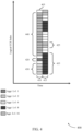
- FIG. 5 illustrates an example resource allocation 500 that supports physical HARQ indicator channel (PHICH) enhancements in accordance with various aspects of the present disclosure.
- PHICH may carry HARQ indicators from a base station 105 to a UE 115.
- a base station 105 may transmit each HARQ indicator in the downlink control region using a set of three REGs 520 (e.g., 12 REs 525 total) that is collectively known as a PHICH group 525.
- three PHICH groups 515-a, 515-b, 515-c are illustrated.
- PHICH groups 515-a, 515-b are contained within a first time interval 505 while PHICH group 515-c is contained in a second time interval 510, though it is possible that a PHICH group 515 may span multiple time intervals.
- the number of PHICH groups 515 may depend on the cell bandwidth as well as one or more configurable parameters.
- Each PHICH group 515 may be mapped to REGs 520 that have not already been assigned to the PCFICH.
- the REs 525 within a given REG 520 may not be contiguous.
- four PHICH REs 525-b may be separated by one or more occupied REs 525-a (e.g., which may be assigned to PCFICH).
- these PHICH groups 515 may not be dedicated to a single UE 115; instead each PHICH group 515 may be shared by multiple (e.g., up to eight) UEs 115 (e.g., by assigning each UE 115 a different orthogonal sequence index).
- each PHICH group may include 12 REs 525, which may be multiplexed with multiple PHICHs each associated with a given UE 115 (e.g., in a code division multiplexing (CDM) manner).
- CDM code division multiplexing
- a UE 115 may retransmit the data with the same parameters (e.g., bandwidth, coding rate, etc.) that it used for the first transmission.
- two or more PHICH REs 525-b may be bundled for a single PHICH transmission for an HRLLC-configured UE 115.
- the bundled PHICH REs 525-b can come from different PHICH groups 515 (e.g., different frequency and/or time resources) instead of two or more sequences being used within the same PHICH group 515.
- the bundling rules may be defined explicitly or implicitly.
- the bundling can be done to additionally use sequence n +1 in PHICH group m +1 (e.g., PHICH group 515-b).
- FIG. 6 illustrates an example transmission scheme 600 that supports UL control enhancements in accordance with various aspects of the present disclosure.
- Transmission scheme 600 includes UE 115-c and base station 105-c, each of which may be an example of the corresponding device described with reference to FIGs. 1 and 2 .
- increased reliability e.g., for HRLLC
- UE 115-c may send HARQ acknowledgements of downlink transmissions received from a base station 105 using physical uplink control channel (PUCCH) resources.
- PUCCH may additionally carry other uplink control information (e.g., CSI feedback), as described below.
- CSI feedback e.g., CSI feedback
- HARQ acknowledgements may be sent using n+3 timing and/or n+4 timing.
- the uplink coverage e.g., the distance away from a base station over which uplink communications 605 may still be received within geographic coverage area 110-c
- resource bundling e.g., time, frequency, spatial, etc.
- the improvement in coverage e.g., by time-domain bundling
- UE 115-c may be configured with multiple CCs, and over each CC, one or two TBs can be sent in a MIMO fashion. Without spatial multiplexing, for each CC, an ACK/NAK bit may be needed. But as disclosed herein, instead of sending two bits in the UL, the bits may be bundled and one bit may be sent as HARQ feedback for multiple CCs. This may be referred to as spatial bundling or referred to as spatial multiplexing and may increase the reliability of successful decoding of the control information 610.
- Time-domain bundling may include bundling ACK/NAK bits associated with TBs sent over different subframes.
- Frequency-domain bundling may include bundling ACK/NAK bits associated with TBs send on the DL over different CCs.
- DL CC 605-a may include TBs sent during subframes 610-a and 610-b.
- HARQ feedback for TBs sent during subframes 610-a and 610-b which may include bundled ACK/NAK bits, may be sent on UL CC 605-b in UCI sent during TTI 615. This may be referred to as time-domain bundling or time bundling.
- DL CC 605-a may include a TB send during subframe 610-a and DL CC 605-c may include a TB send during subframe 610-c.
- HARQ feedback for TBs sent during subframes 610-a and 610-c may be sent on UL CC 605-b in UCI sent during TTI 615. This may be referred to as frequency-domain bundling or frequency bundling. In some cases, these bundling techniques may be used in various combinations.
- uplink control information 610 may carry ACK/NACK information for multiple TTIs and/or codewords (e.g., which may be referred to as block ACK/NACK). In some cases, ACK/NACK bits may be sent repeatedly over multiple TTIs.
- UE 115-c may be configured to drop the CSI in favor of ACK/NACK for HRLLC services. For example, if UCI element 625-b is allocated to carry CSI, UE 115-c may be configured to assign some or all of the resources of UCI element 625-b to carry ACK/NACK for HRLLC services.
- the CSI may be dropped completely or otherwise have its payload limited (e.g., only rank indicator (RI), precoding matrix indicator (PMI), and precoding type indicator (PTI) without channel quality indicator (CQI)).
- scheduling request (SR) transmissions may also be associated with improved performance (e.g., higher reliability and/or lower latency) when UL HRLLC services are configured. For example, SR transmissions may be combined with HARQ-ACK.
- uplink control information 610-a, 610-b on respective uplink carriers 605-a, 605-b may carry respective CSI feedback.
- one set of CSI feedback e.g., for uplink control information 610-a
- regular services e.g., assuming 10% block error rate (BLER) after initial transmission
- Another set of CSI feedback e.g., for uplink control information 610-b
- HRLLC services e.g., assuming 1% BLER after initial transmission.
- further considerations may include introduction of two or more interference hypotheses.
- One such hypothesis may correspond to no or minimal inter-cell HRLLC interference while another hypothesis may correspond to other (e.g., typical) inter-cell HRLLC interference.
- Such a multi-hypothesis scheme may be realized by two sets of interference measurement resources (IMRs) for CSI feedback, where each set of IMRs may have different inter-cell HRLLC interference characteristics.
- IMRs interference measurement resources
- UE 115-c may be configured to transmit both sets or only one set (e.g., such that the HRLLC CSI feedback of uplink control information 610-b may be prioritized in high interference scenarios).
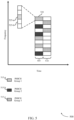
- FIG. 7 illustrates an example of a resource allocation 700 that supports PUSCH enhancements in accordance with various aspects of the present disclosure.
- higher layer-configured offset(s) 715 may be used to determine the amount of resources for CQI/PMI, RI/PTI, and ACK/NACK separately.
- the amount of resources for UCI may further depend on the PUSCH parameters (e.g., modulation and coding scheme (MCS), bandwidth, etc.).
- MCS modulation and coding scheme
- a separate set of parameters for determining the amount of resources for UCI may be introduced. For example, a first set of offsets 715-a may be used if the UCI is not for HRLLC, and a second set of offsets 715-b (e.g., which may be associated with a wider bandwidth) may be used if the UCI is for HRLLC services.
- a first set of offsets 715-a may be used if the UCI is not for HRLLC
- a second set of offsets 715-b e.g., which may be associated with a wider bandwidth
- two or more offsets 715-a, 715-b, 715-c may be configured such that a UE 115 may determine (e.g., dynamically) which offset 715 is to be used for a given UCI transmission on PUSCH resources 705.
- a dynamic scheme may enable additional flexibility for a base station 105.
- the determination may be done based on a determination of HRLLC compared to HRLLC PDSCH transmissions (i.e., the ACK/NACK corresponding to the PDSCH transmissions), an indicator in a DCI grant, etc.
- ACK/NACK resources e.g., offset 715-b
- a second RRC-configured offset e.g., offset 715-a
- FIG. 8 illustrates a wireless communication system 800 that supports UL power control enhancements in accordance with various aspects of the present disclosure.
- Wireless communication system 800 includes base station 105-d and UE 115-d, each of which may be an example of the corresponding device as described with reference to FIGs. 1 , 2 , and 6 .
- different open loop power control parameters may be used for HRLLC communications 810 compared to non-HRLLC communications 805, which may include communications according to earlier releases of the LTE standard, MBB communications, broadcast communications, or the like.
- HRLLC-specific power control parameters e.g., alpha for partial/full path loss compensation, P_0_PUSCH or P_0_PUCCH, etc.
- HRLLC-specific power control parameters may be separately indicated for HRLLC communications 810 and non-HRLLC communications 805.
- UE-specific power control parameters may be separately configured for HRLLC communications 810 and non-HRLLC communications 805.
- the determination of which set to use may be based on aspects of the HRLLC communications 810 and non-HRLLC communications 805 (e.g., an amount of data to be transmitted).
- the different control parameters may allow for independent control of transmission power for HRLLC communications 810 and non-HRLLC communications 805 (e.g., such that UE 115-d may transmit HRLLC communication 810-a at a lower power initially before increasing the transmission power of HRLLC communication 810-b without necessarily altering the transmission power of non-HRLLC communication 805).
- the total transmission power for UE 115-d may be limited (e.g., due to interference, battery constraints, etc.) such that the increase in transmission power from HRLLC communication 810-a to HRLLC communication 810-b may be at least partially offset by a complementary decrease in transmission power for non-HRLLC communication 805.
- Analogous enhancements for closed/inner-loop power control are also considered. However, in some cases there may not be a strong need to introduce separate closed/inner loop power control for HRLLC communications 810 and non-HRLLC communications 805 (e.g., such that both may use the same closed loop power control). Similarly, there may not be a strong need to have backhaul-related enhancements (e.g., because the current backhaul framework may be sufficient to support the enhancements described herein).
- FIG. 9 illustrates a process flow 900 that supports high reliability low latency configuration for wireless communications systems in accordance with various aspects of the present disclosure.
- Process flow 900 includes UE 115-e and base station 105-e, each of which may be an example of the corresponding device described with reference to FIG. 1 .
- base station 105-e may establish a connection with UE 115-e.
- the connection established at 905 may be an example of a communication link 125 as described with reference to FIG. 1 .
- the wireless communications system within which UE 115-e and base station 105-e establish the connection at 905 may support a first wireless service having a first target decoding error rate and a first target latency value and a second wireless service having a second target decoding error rate that is higher than the first target decoding error rate or a second target latency that is higher than the first target latency value.
- the first wireless service may be for HRLLC.
- the second wireless service may have both the second target decoding error rate and the second target latency value.
- the second wireless service may have the second target decoding error rate and a third target latency value that is lower than the first target latency value. In some examples, the second wireless service may have a third target decoding error rate that is lower than the first target decoding error rate and the second target latency value.
- base station 105-e may identify time-frequency resources for assignment to UE 115-e for the first wireless service, wherein the first wireless service and the second wireless service have TTIs of a same duration. In some cases, the TTIs are 1 ms. In various examples, the resources identified at 910 may depend on aspects of the wireless communication system such as a supported traffic load, processing capability of UE 115-e, an amount of a given type of traffic to be transmitted, etc. In some examples, the resources identified at 910 may depend on the first target decoding error rate.
- base station 105-e may optionally transmit RRC signaling to UE 115-e to configure UE 115-e for the first wireless service.
- base station 105-e may transmit a control message that assigns the resources identified at 910 for the first wireless service to UE 115-e during one of the TTIs.
- the control message at 920 is transmitted based at least in part on configuring the UE 115-e for the first wireless service (e.g., using RRC signaling at 915).
- the control message comprises at least one of a radio network temporary identifier (RNTI), a DCI format, a DCI indication, a set of control candidates, a semi-static configuration, or any combination thereof that indicates that the assigned resources are associated with the first wireless service.
- RNTI radio network temporary identifier
- base station 105-e may optionally transmit DCI associated with the first wireless service using a first set of candidates for the wireless service.
- the first set of candidates for the wireless service may be identified in the control signaling at 920.
- the number of aggregation levels for the first set of candidates may be different from a number of aggregation levels associated with a second set of candidates for the second wireless service.
- base station 105-e may optionally transmit power control parameters to UE 115-a.
- base station 105-e may transmit power control parameters associated with the first wireless service (e.g., HRLCC power control parameters) or with the second wireless service (e.g., non-HRLCC power control parameters).
- base station 105-e may optionally transmit an indication of a first set of offsets to UE 115-a to be used for piggy-backing UCI with a PUSCH message associated with the first wireless service, and/or an indication of a second set of offsets to be used for piggy-backing UCI with a PUSCH message associated with the second wireless service.
- the indication of the set of offsets is transmitted via either the DCI (e.g., at 925) or RRC signaling (e.g., at 915).
- base station 105-e may optionally receive, from UE 115-e, a data message of the first wireless service on the assigned resources for the first wireless service (e.g., the resources identified at 910).
- base station 105-e may optionally transmit an uplink feedback message that comprises HARQ feedback using spatial, time-domain, or frequency-domain bundling from UE 115-e in response to the data message.
- uplink feedback refers to feedback for an uplink transmission rather than indicating that the feedback is transmitted in the uplink direction.
- a set of time-frequency resources for one of the two or more sets of feedback resources is different from a set of time-frequency resources for another of the two or more sets of feedback resources.
- base station 105-e may optionally receive a downlink feedback message that comprises a bundle of one or more ACK messages or one or more NACK messages from UE 115-e.
- the downlink feedback e.g., HARQ feedback sent from a UE to base station 105-e in response to a downlink transmission
- the downlink feedback message includes no CSI feedback.
- the downlink feedback message includes CSI feedback without a CQI.
- an amount of CQI information included in the CSI feedback associated with the first wireless service is different than an amount of CQI information included in the CSI feedback associated with the second wireless service.
- base station 105-e may optionally receive UCI for the first wireless service concurrently with a PUSCH message from UE 115-e.
- UCI for the first wireless service may be piggy-backed with a PUSCH message.
- UCI may be piggy-based with a PUSCH message in accordance with the first set of offsets received at 935.
- the UCI for the first wireless service comprises a different set of parameters than UCI for the second wireless service.
- FIG. 10 illustrates a process flow 1000 that supports high reliability low latency configuration for wireless communications systems in accordance with various aspects of the present disclosure.
- Process flow 1000 includes UE 115-f and base station 105-f, each of which may be an example of the corresponding device described with reference to FIG. 1 .
- base station 105-f may establish a connection with UE 115-f.
- the connection established at 1005 may be an example of a communication link 125 as described with reference to FIG. 1 .
- the wireless communications system within which UE 115-f and base station 105-f establish the connection at 1005 may support a first wireless service having a first target decoding error rate and a first target latency value and a second wireless service having a second target decoding error rate that is higher than the first target decoding error rate or a second target latency value that is higher than the first target latency value.
- the first wireless service may be for HRLLC.
- the second wireless service may have the second target decoding error rate and the second target latency rate.
- the second wireless service may have the second target decoding error rate and a third target latency value that is lower than the first target latency value. In some examples, the second wireless service may have a third target decoding error rate that is lower than the first target decoding error rate and the second target latency value.
- UE 115-f may optionally receive RRC signaling from base station 105-f that configures UE 115-f to monitor for resource assignments for the first wireless service.
- the UE 115-f may receive RRC signaling (e.g., at 1010 or at some other time) that configures the UE 115-f to monitor for resource assignments for the second wireless service.
- the second wireless service may be associated with a latency that is less than a latency associated with the first wireless service (e.g., such that the first wireless service may be associated with a higher reliability and a higher latency).
- the configuration of UE 115-f may be based at least in part on a TA for UE 115-f and/or a transport block size (TBS) limitation.
- TBS transport block size
- UE 115-f may receive, during a first TTI, a control message from base station 105-f.
- the first and second wireless services may have a same TTI duration.
- the UE 115-f may receive the control message based at least in part on receiving the RRC signaling at 1010.
- the first TTI comprises a LTE subframe.
- the control message comprises at least one of a RNTI, a DCI format, a DCI indication, a set of control candidates, a semi-static configuration, or any combination thereof that indicates that the assigned resources are associated with the first wireless service.
- UE 115-f may optionally determine a first set of decoding candidates within a UESS based at least in part on the control message received at 1015.
- UE 115-f may receive, from base station 105-f, DCI using the first set of decoding candidates determined at 1020.
- UE 115-f may optionally receive a first set of UE-specific power control parameters, wherein the first set of power control parameters is associated with the first wireless service, and may receive a second set of UE-specific power control parameters, wherein the second set of power control parameters is associated with the second wireless service.
- UE 115-f may optionally receive a first indication of a first set of offsets to be used for piggy-backing UCI with a PUSCH message, wherein the PUSCH message is associated with the first wireless service.
- UE 115-f may optionally receive a first indication of a first offset to be used for piggy-backing UCI with a first PUSCH message, wherein the first PUSCH message is associated with the first wireless service, and may optionally receive a second indication of a second offset to be used for piggy-backing UCI with a second PUSCH message, wherein the second PUSCH message is associated with the second wireless service.
- the first indication is received via either DCI (e.g., at 1025) or RRC signaling (e.g., at 1010).
- UE 115-f may determine resources assigned for the first wireless service based at least in part on the control message received at 1015. In some cases, the resources may be determined based at least in part on the DCI received at 1025.
- UE 115-f may receive data during the first TTI or transmit data during a second TTI using the resources assigned for the first wireless service. In some cases, UE 115-f may transmit UCI piggybacked with a PUSCH message. In some cases, the UCI is piggy-backed with the PUSCH message in accordance with the first set of offsets received at 1035. In some cases, the UCI for the first wireless service comprises a different set of parameters than UCI for the second wireless service.
- UE 115-f may optionally transmit a feedback message responsive to at least the control message and based at least in part on a success of receiving data for the first wireless service during the first TTI.
- the feedback message comprises HARQ feedback transmitted using spatial bundling, time-domain bundling, or frequency-domain bundling, as described herein. Bundling for the first wireless service may be different from bundling for the second wireless service.
- transmitting the feedback message comprises transmitting at least one of an ACK or NACK within a predetermined time period following the first TTI. In some cases, the predetermined time period comprises at least three TTIs.
- the feedback message includes no CSI feedback. In some cases, the feedback message includes CSI feedback without a CQI.
- UE 115-f may optionally transmit a first set of CSI feedback associated with the first wireless service, and transmit a second set of feedback associated with the second wireless service.
- the first set of CSI feedback and the second set of CSI feedback differ in an amount of CQI information included in each of the first set of CSI feedback and the second set of CSI feedback.
- UE-115-f may optionally determine whether to use the first offset or the second offset for piggy-backing the UCI with a PUSCH message. In some cases, the determination may be based at least in part on the control message received at 1015.
- UE-115-f may optionally transmit UCI.
- the UCI may be piggy-backed with a PUSCH message in accordance with the first set of offsets.
- the UCI in accordance with a determination at 1060 to use the first offset, may be piggy-backed with a PUSCH message in accordance with the first offset
- FIG. 11 shows a block diagram 1100 of a wireless device 1105 that supports high reliability low latency configuration for wireless communications systems in accordance with aspects of the present disclosure.
- Wireless device 1105 may be an example of aspects of a base station 105 as described with reference to FIG. 1 .
- Wireless device 1105 may include receiver 1110, base station service manager 1115, and transmitter 1120.
- Wireless device 1105 may also include a processor. Each of these components may be in communication with one another (e.g., via one or more buses).
- Receiver 1110 may receive information such as packets, user data, or control information associated with various information channels (e.g., control channels, data channels, and information related to high reliability low latency configuration for wireless communications systems, etc.). Information may be passed on to other components of the device.
- the receiver 1110 may be an example of aspects of the transceiver 1435 described with reference to FIG. 14 .
- the receiver 1110 may utilize a single antenna or a set of antennas.
- Base station service manager 1115 may be an example of aspects of the base station service manager 1415 described with reference to FIG. 14 .
- Base station service manager 1115 may identify resources for assignment to a user equipment UE for the first wireless service, where the first wireless service and the second wireless service have TTIs of a same duration.
- Base station service manager 1115 or at least some of its various sub-components may be implemented in hardware, software executed by a processor, firmware, or any combination thereof.
- the functions of the base station service manager 1115 or at least some of its various sub-components may be executed by a general-purpose processor, a digital signal processor (DSP), an application-specific integrated circuit (ASIC), an field-programmable gate array (FPGA) or other programmable logic device, discrete gate or transistor logic, discrete hardware components, or any combination thereof designed to perform the functions described in the present disclosure.
- DSP digital signal processor
- ASIC application-specific integrated circuit
- FPGA field-programmable gate array
- the base station service manager 1115 and/or at least some of its various sub-components may be physically located at various positions, including being distributed such that portions of functions are implemented at different physical locations by one or more physical devices.
- base station service manager 1115 or at least some of its various sub-components may be a separate and distinct component in accordance with various aspects of the present disclosure.
- base station service manager 1115 or at least some of its various sub-components may be combined with one or more other hardware components, including but not limited to an I/O component, a transceiver, a network server, another computing device, one or more other components described in the present disclosure, or a combination thereof in accordance with various aspects of the present disclosure.
- Transmitter 1120 may transmit signals generated by other components of the device. Transmitter 1120 may transmit a control message that assigns the resources for the first wireless service to the UE during one of the TTIs. In some examples, the transmitter 1120 may be collocated with a receiver 1110 in a transceiver module. For example, the transmitter 1120 may be an example of aspects of the transceiver 1435 described with reference to FIG. 14 . The transmitter 1120 may utilize a single antenna or a set of antennas.
- FIG. 12 shows a block diagram 1200 of a wireless device 1205 that supports high reliability low latency configuration for wireless communications systems in accordance with aspects of the present disclosure.
- Wireless device 1205 may be an example of aspects of a wireless device 1105 or a base station 105 as described with reference to FIGs. 1 and 11 .
- Wireless device 1205 may include receiver 1210, base station service manager 1215, and transmitter 1220.
- Wireless device 1205 may also include a processor. Each of these components may be in communication with one another (e.g., via one or more buses).
- Receiver 1210 may receive information such as packets, user data, or control information associated with various information channels (e.g., control channels, data channels, and information related to high reliability low latency configuration for wireless communications systems, etc.). Information may be passed on to other components of the device.
- the receiver 1210 may be an example of aspects of the transceiver 1435 described with reference to FIG. 14 .
- the receiver 1210 may utilize a single antenna or a set of antennas.
- Base station service manager 1215 may be an example of aspects of the base station service manager 1415 described with reference to FIG. 14 .
- Base station service manager 1215 may also include resource component 1225 and message transmitter 1230.
- Resource component 1225 may identify resources for assignment to a UE for the first wireless service, where the first wireless service and the second wireless service have TTIs of a same duration.
- the second wireless service has a second target latency value that is higher than the first target latency value.
- the second wireless service has a third target latency value that is lower than the first target latency value.
- Message transmitter 1230 may, in combination with transmitter 1220, generate and transmit a control message that assigns the resources for the first wireless service to the UE during one of the TTIs.
- Message transmitter 1230 may be a sequence generator, for example.
- the control message includes at least one of a RNTI, a DCI format, a DCI indication, a set of control candidates, a semi-static configuration, or any combination thereof that indicates that the assigned resources are associated with the first wireless service.
- Transmitter 1220 may transmit signals generated by other components of the device.
- the transmitter 1220 may be collocated with a receiver 1210 in a transceiver module.
- the transmitter 1220 may be an example of aspects of the transceiver 1435 described with reference to FIG. 14 .
- the transmitter 1220 may utilize a single antenna or a set of antennas.
- FIG. 13 shows a block diagram 1300 of a base station service manager 1315 that supports high reliability low latency configuration for wireless communications systems in accordance with aspects of the present disclosure.
- the base station service manager 1315 may be an example of aspects of a base station service manager 1115, a base station service manager 1215, or a base station service manager 1415 described with reference to FIGs. 11 , 12 , and 14 .
- the base station service manager 1315 may include resource component 1320, message transmitter 1325, RRC component 1330, downlink control transmitter 1335, data component 1340, feedback component 1345, and uplink control component 1350. Each of these modules may communicate, directly or indirectly, with one another (e.g., via one or more buses).
- Resource component 1320 may identify resources for assignment to a UE for the first wireless service, where the first wireless service and the second wireless service have TTIs of a same duration. In some cases, the first wireless service has a first target latency value and the second wireless service has a second target latency value that is higher than the first target latency value. In some cases, the first wireless service has a first target latency value and the second wireless service has a third target latency value that is lower than the first target latency value. Resource component 1320 may optionally identify second resources for assignment to a UE for the second wireless service. In some cases, resource component 1320 identifies the resources by selecting resources based at least in part on the first target decoding error rate or the first target latency value of the first wireless service. In some cases, resource component 1320 identifies the second resources by selecting second resources based at least in part on the second target decoding rate or the second target latency value of the second wireless service.
- Message transmitter 1325 may, in combination with a transmitter or transceiver, generate and transmit a control message that assigns the resources for the first wireless service to the UE during one of the TTIs.
- the control message includes at least one of a first RNTI, a first DCI format, a first DCI indication, a first set of control candidates, a first semi-static configuration, or any combination thereof that indicates that the assigned resources are associated with the first wireless service.
- Message transmitter 1325 may optionally, in combination with a transmitter or transceiver, generate and transmit a second control message that assigns the resources for the second wireless service to the UE during one of the TTIs.
- the second control message includes at least one of a second RNTI, a second DCI format, a second DCI indication, a second set of control candidates, a second semi-static configuration, or any combination thereof that indicates that the assigned resources are associated with the second wireless service.
- RRC component 1330 may, in combination with a transmitter or transceiver, generate and transmit, to the UE, RRC signaling that configures the UE for the first wireless service, where the control message is transmitted based on configuring the UE for the first wireless service.
- Downlink control transmitter 1335 may, in combination with a transmitter or transceiver, generate and transmit downlink control information associated with the first wireless service using a first set of decoding candidates for the first wireless service. In some cases, a number of aggregation levels for the first set of decoding candidates is different from a number of aggregation levels associated with a second set of decoding candidates for the second wireless service.
- downlink control transmitter 1335 may transmit, to the UE, a first indication of a first set of offsets to be used for piggy-backing uplink control information with a PUSCH message associated with the first wireless service, and transmit, to the UE, a second indication of a second set of offsets to be used for piggy-backing uplink control information with a second PUSCH message associated with the second wireless service.
- downlink control transmitter 1335 may transmit, to the UE, a first set of power control parameters associated with the first wireless service, and a second set of power control parameters associated with the second wireless service.
- Data component 1340 may, in combination with a receiver or transceiver, receive, from the UE, a data message of the first wireless service on the assigned resources for the first wireless service.
- Feedback component 1345 may, in combination with a transmitter or transceiver, generated and transmit a feedback message to the UE that includes ACK/NAK bundling (e.g., spatial bundling, time-domain bundling, or frequency-domain bundling) in response to the data message and receive, from the UE, a feedback message responsive to the control message that is transmitted using spatial bundling, time-domain bundling, or frequency-domain bundling, as described herein.
- Bundling for the first wireless service may be different from bundling for the second wireless service.
- the feedback message from the UE includes a scheduling request.
- the feedback message from the UE does not include channel state information (CSI) feedback.
- CSI channel state information
- the feedback message from the UE includes CSI feedback without a channel quality indicator (CQI).
- feedback component 1345 may receive, from the UE, a first set of channel state information (CSI) feedback associated with the first wireless service, and a second set of CSI feedback associated with the second wireless service.
- CSI channel state information
- the first set of CSI feedback and the second set of CSI feedback differ in the amount of channel quality indicator (CQI) information that is included in the first and second sets of CSI feedback.
- the first set of CSI feedback is associated with a first set of interference hypotheses and the second set of CSI feedback is associated with a second set of interference hypotheses.
- Uplink control component 1350 may, in combination with a receiver or transceiver, receive, from the UE, uplink control information for the first wireless service concurrently or piggybacked with a PUSCH message.
- the uplink control information for the first wireless service includes a different set of parameters than uplink control information for the second wireless service.
- FIG. 14 shows a diagram of a system 1400 including a device 1405 that supports high reliability low latency configuration for wireless communications systems in accordance with aspects of the present disclosure.
- Device 1405 may be an example of or include the components of wireless device 1105, wireless device 1205, or a base station 105 as described above, e.g., with reference to FIGs. 1 , 11 and 12 .
- Device 1405 may include components for bi-directional voice and data communications including components for transmitting and receiving communications, including base station service manager 1415, processor 1420, memory 1425, software 1430, transceiver 1435, antenna 1440, network communications manager 1445, and base station communications manager 1450. These components may be in electronic communication via one or more busses (e.g., bus 1410).
- Device 1405 may communicate wirelessly with one or more UEs 115.
- Processor 1420 may include an intelligent hardware device, (e.g., a general-purpose processor, a DSP, a central processing unit (CPU), a microcontroller, an ASIC, an FPGA, a programmable logic device, a discrete gate or transistor logic component, a discrete hardware component, or any combination thereof).
- processor 1420 may be configured to operate a memory array using a memory controller.
- a memory controller may be integrated into processor 1420.
- Processor 1420 may be configured to execute computer-readable instructions stored in a memory to perform various functions (e.g., functions or tasks supporting high reliability low latency configuration for wireless communications systems).
- Memory 1425 may include random access memory (RAM) and read only memory (ROM).
- the memory 1425 may store computer-readable, computer-executable software 1430 including instructions that, when executed, cause the processor to perform various functions described herein.
- the memory 1425 may contain, among other things, a basic input/output system (BIOS) which may control basic hardware and/or software operation such as the interaction with peripheral components or devices.
- BIOS basic input/output system
- Software 1430 may include code to implement aspects of the present disclosure, including code to support high reliability low latency configuration for wireless communications systems.
- Software 1430 may be stored in a non-transitory computer-readable medium such as system memory or other memory. In some cases, the software 1430 may not be directly executable by the processor but may cause a computer (e.g., when compiled and executed) to perform functions described herein.
- Transceiver 1435 may communicate bi-directionally, via one or more antennas, wired, or wireless links as described above.
- the transceiver 1435 may represent a wireless transceiver and may communicate bi-directionally with another wireless transceiver.
- the transceiver 1435 may also include a modem to modulate the packets and provide the modulated packets to the antennas for transmission, and to demodulate packets received from the antennas.
- the wireless device may include a single antenna 1440. However, in some cases the device may have more than one antenna 1440, which may be capable of concurrently transmitting or receiving multiple wireless transmissions.
- Network communications manager 1445 may manage communications with the core network (e.g., via one or more wired backhaul links). For example, the network communications manager 1445 may manage the transfer of data communications for client devices, such as one or more UEs 115.
- Base station communications manager 1450 may manage communications with other base station 105, and may include a controller or scheduler for controlling communications with UEs 115 in cooperation with other base stations 105. For example, the base station communications manager 1450 may coordinate scheduling for transmissions to UEs 115 for various interference mitigation techniques such as beamforming or joint transmission. In some examples, base station communications manager 1450 may provide an X2 interface within an LTE/LTE-A wireless communication network technology to provide communication between base stations 105.
- FIG. 15 shows a block diagram 1500 of a wireless device 1505 that supports high reliability low latency configuration for wireless communications systems in accordance with aspects of the present disclosure.
- Wireless device 1505 may be an example of aspects of a UE 115 as described with reference to FIG. 1 .
- Wireless device 1505 may include receiver 1510, UE service manager 1515, and transmitter 1520.
- Wireless device 1505 may also include a processor. Each of these components may be in communication with one another (e.g., via one or more buses).
- Receiver 1510 may receive information such as packets, user data, or control information associated with various information channels (e.g., control channels, data channels, and information related to high reliability low latency configuration for wireless communications systems, etc.). Receiver 1510 may receive, at a UE and during a first TTI, a control message from a base station, where the first wireless service and the second wireless service have TTIs of a same duration. Receiver 1510 may also receive data during the first TTI. Information may be passed on to other components of the device. Receiver 1510 may be an example of aspects of the transceiver 1835 described with reference to FIG. 18 . The receiver 1510 may utilize a single antenna or a set of antennas.
- various information channels e.g., control channels, data channels, and information related to high reliability low latency configuration for wireless communications systems, etc.
- Receiver 1510 may receive, at a UE and during a first TTI, a control message from a base station, where the first wireless service and the second wireless service have TTIs
- UE service manager 1515 may be an example of aspects of the UE service manager 1815 described with reference to FIG. 18 .
- UE service manager 1515 may determine resources assigned for the first wireless service based on the control message.
- UE service manager 1515 or at least some of its various sub-components may be implemented in hardware, software executed by a processor, firmware, or any combination thereof. If implemented in software executed by a processor, the functions of the UE service manager 1515 or at least some of its various sub-components may be executed by a general-purpose processor, a DSP, an ASIC, an FPGA or other programmable logic device, discrete gate or transistor logic, discrete hardware components, or any combination thereof designed to perform the functions described in the present disclosure.
- the UE service manager 1515 or at least some of its various sub-components may be physically located at various positions, including being distributed such that portions of functions are implemented at different physical locations by one or more physical devices.
- UE service manager 1515 or at least some of its various sub-components may be a separate and distinct component in accordance with various aspects of the present disclosure.
- UE service manager 1515 or at least some of its various sub-components may be combined with one or more other hardware components, including but not limited to an I/O component, a transceiver, a network server, another computing device, one or more other components described in the present disclosure, or a combination thereof in accordance with various aspects of the present disclosure.
- Transmitter 1520 may transmit signals generated by other components of the device. Transmitter 1520 may transmit data during a second TTI using the resources assigned for the first wireless service. In some examples, the transmitter 1520 may be collocated with a receiver 1510 in a transceiver module. For example, the transmitter 1520 may be an example of aspects of the transceiver 1835 described with reference to FIG. 18 . The transmitter 1520 may utilize a single antenna or a set of antennas.
- FIG. 16 shows a block diagram 1600 of a wireless device 1605 that supports high reliability low latency configuration for wireless communications systems in accordance with aspects of the present disclosure.
- Wireless device 1605 may be an example of aspects of a wireless device 1505 or a UE 115 as described with reference to FIGs. 1 and 15 .
- Wireless device 1605 may include receiver 1610, UE service manager 1615, and transmitter 1620.
- Wireless device 1605 may also include a processor. Each of these components may be in communication with one another (e.g., via one or more buses).
- Receiver 1610 may receive information such as packets, user data, or control information associated with various information channels (e.g., control channels, data channels, and information related to high reliability low latency configuration for wireless communications systems, etc.). Information may be passed on to other components of the device.
- the receiver 1610 may be an example of aspects of the transceiver 1835 described with reference to FIG. 18 .
- the receiver 1610 may utilize a single antenna or a set of antennas.
- UE service manager 1615 may be an example of aspects of the UE service manager 1815 described with reference to FIG. 18 .
- UE service manager 1615 may also include control message component 1625, resource component 1630, and data component 1635.
- Control message component 1625 may, in combination with receiver 1610, receive, at a UE and during a first TTI, a control message from a base station, where the first wireless service and the second wireless service have TTIs of a same duration.
- the control message includes at least one of a RNTI, a DCI format, a DCI indication, a set of control candidates, a semi-static configuration, or any combination thereof that indicates that the assigned resources are associated with the first wireless service.
- Control message component 1625 may optionally receive, at the UE and during a third TTI, a second control message from the base station.
- the second control message includes at least one of a second RNTI, a second DCI format, a second DCI indication, a second set of control candidates, a second semi-static configuration, or any combination thereof that indicates that the assigned resources are associated with the second wireless service.
- Resource component 1630 may determine resources assigned for the first wireless service based on the control message.
- the first wireless service has a first target latency value and the second wireless service has a second target latency value that is higher than the first target latency value.
- Data component 1635 may, in combination with receiver 1610, receive data during the first TTI or third TTI or, in combination with transmitter 1620, transmit data during a second TTI or fourth TTI using the resources assigned for the first wireless service or second wireless service, respectively.
- the first TTI includes a LTE subframe.
- Transmitter 1620 may transmit signals generated by other components of the device.
- the transmitter 1620 may be collocated with a receiver 1610 in a transceiver module.
- the transmitter 1620 may be an example of aspects of the transceiver 1835 described with reference to FIG. 18 .
- the transmitter 1620 may utilize a single antenna or a set of antennas.
- FIG. 17 shows a block diagram 1700 of a UE service manager 1715 that supports high reliability low latency configuration for wireless communications systems in accordance with aspects of the present disclosure.
- the UE service manager 1715 may be an example of aspects of a UE service manager 1815 described with reference to FIGs. 15 , 16 , and 18 .
- the UE service manager 1715 may include control message component 1720, resource component 1725, data component 1730, RRC signaling component 1735, feedback component 1740, candidate component 1745, downlink control transmitter 1750, and uplink transmitter 1755. Each of these modules may communicate, directly or indirectly, with one another (e.g., via one or more buses).
- Control message component 1720 may, in combination with a receiver or transceiver, receive, at a UE and during a first TTI, a control message from a base station, where the first wireless service and the second wireless service have TTIs of a same duration.
- the control message includes at least one of a RNTI, a DCI format, a DCI indication, a set of control candidates, a semi-static configuration, or any combination thereof that indicates that the assigned resources are associated with the first wireless service.
- Control message component 1720 may optionally, in combination with a receiver or transceiver, receive, at a UE and during a third TTI, a second control message from the base station, where the second control message includes at least one of a second RNTI, a second DCI format, a second DCI indication, a second set of control candidates, a second semi-static configuration, or any combination thereof that indicates that the assigned resources are associated with the second wireless service.
- Control message component 1720 may optionally receive a first set of UE-specific power control parameters associated with the first wireless service and a second set of UE-specific power control parameters associated with the second wireless service.
- Resource component 1725 may determine resources assigned for the first wireless service based on the control message.
- the first wireless service has a first target latency value and the second wireless service has a second target latency value that is higher than the first target latency value.
- the first wireless service has a first target latency value and the second wireless service has a third target latency value that is lower than the first target latency value.
- Data component 1730 may, in combination with a receiver or transceiver, receive data during the first or third TTI or transmitting data during a second or fourth TTI using the resources assigned for the first wireless service or second wireless service, respectively.
- the first TTI includes a LTE subframe.
- RRC signaling component 1735 may, in combination with a receiver or transceiver, receive RRC signaling that configures the UE to monitor for resource assignments for the first wireless service, where the control message is received based on receiving the RRC signaling.
- RRC signaling component 1735 may optionally receive RRC signaling that configures the UE to monitor for resource assignments for the second wireless service.
- the second wireless service has a second target latency value that is higher than the first target latency value of the first wireless service.
- the second wireless service has a third target latency value that is lower than the first target latency value of the first wireless service.
- the configuration of the UE is based on a timing advance for the UE or a TBS limitation.
- RRC signaling component 1735 may optionally receive, via RRC signaling, a first indication of a first set of offsets to be used for piggybacking the UCI with a PUSCH message associated with the first wireless service.
- Feedback component 1740 may, in combination with a transmitter or transceiver, transmit a feedback message responsive to the control message based on a success of receiving data for the first wireless service during the first TTI.
- the feedback message comprises HARQ feedback transmitted using spatial bundling, time-domain bundling, or frequency-domain bundling, as described herein. Bundling for the first wireless service may be different from bundling for the second wireless service.
- the feedback message includes no CSI feedback.
- the feedback message includes CSI feedback without a CQI.
- Feedback component 1740 may optionally transmit a first set of CSI feedback associated with the first wireless service and a second set of CSI feedback associated with the second wireless service. In some cases, the first set of CSI feedback and the second set of CSI feedback differ in an amount of CQI information that is included in the first set and the second set.
- transmitting the feedback message includes transmitting at least one of an ACK message or a NACK within a predetermined time period following the first TTI.
- the predetermined time period includes at least three TTIs.
- Candidate component 1745 may determine a first set of decoding candidates within a UE-specific search space based on the control message.
- Downlink control component 1750 may, in combination with a receiver or transceiver, receive, from the base station, DCI using the first set of decoding candidates, where determining resources assigned for the first wireless service is based on the DCI. Downlink control component 1750 may optionally receive, via DCI, a first indication of a first set of offsets to be used for piggybacking the UCI with a PUSCH message associated with the first wireless service.
- Uplink transmitter 1755 may, in combination with a transmitter or transceiver, transmit uplink control information (UCI) piggybacked with a PUSCH message.
- UCI uplink control information
- the uplink control information for the first wireless service includes a different set of parameters than uplink control information for the second wireless service.
- the UCI is piggybacked with the PUSCH message in accordance with the first set of offsets.
- FIG. 18 shows a diagram of a system 1800 including a device 1805 that supports high reliability low latency configuration for wireless communications systems in accordance with aspects of the present disclosure.
- Device 1805 may be an example of or include the components of UE 115 as described above, e.g., with reference to FIG. 1 .
- Device 1805 may include components for bi-directional voice and data communications including components for transmitting and receiving communications, including UE service manager 1815, processor 1820, memory 1825, software 1830, transceiver 1835, antenna 1840, and I/O controller 1845. These components may be in electronic communication via one or more busses (e.g., bus 1810).
- Device 1805 may communicate wirelessly with one or more base stations 105.
- Processor 1820 may include an intelligent hardware device, (e.g., a general-purpose processor, a DSP, a CPU, a microcontroller, an ASIC, an FPGA, a programmable logic device, a discrete gate or transistor logic component, a discrete hardware component, or any combination thereof).
- processor 1820 may be configured to operate a memory array using a memory controller.
- a memory controller may be integrated into processor 1820.
- Processor 1820 may be configured to execute computer-readable instructions stored in a memory to perform various functions (e.g., functions or tasks supporting high reliability low latency configuration for wireless communications systems).
- Memory 1825 may include RAM and ROM.
- the memory 1825 may store computer-readable, computer-executable software 1830 including instructions that, when executed, cause the processor to perform various functions described herein.
- the memory 1825 may contain, among other things, a BIOS which may control basic hardware and/or software operation such as the interaction with peripheral components or devices.
- Software 1830 may include code to implement aspects of the present disclosure, including code to support high reliability low latency configuration for wireless communications systems.
- Software 1830 may be stored in a non-transitory computer-readable medium such as system memory or other memory. In some cases, the software 1830 may not be directly executable by the processor but may cause a computer (e.g., when compiled and executed) to perform functions described herein.
- Transceiver 1835 may communicate bi-directionally, via one or more antennas, wired, or wireless links as described above.
- the transceiver 1835 may represent a wireless transceiver and may communicate bi-directionally with another wireless transceiver.
- the transceiver 1835 may also include a modem to modulate the packets and provide the modulated packets to the antennas for transmission, and to demodulate packets received from the antennas.
- the wireless device may include a single antenna 1840. However, in some cases the device may have more than one antenna 1840, which may be capable of concurrently transmitting or receiving multiple wireless transmissions.
- I/O controller 1845 may manage input and output signals for device 1805. I/O controller 1845 may also manage peripherals not integrated into device 1805. In some cases, I/O controller 1845 may represent a physical connection or port to an external peripheral. In some cases, I/O controller 1845 may utilize an operating system such as iOS ® , ANDROID ® , MS-DOS ® , MS-WINDOWS ® , OS/2 ® , UNIX ® , LINUX ® , or another known operating system. In other cases, I/O controller 1845 may represent or interact with a modem, a keyboard, a mouse, a touchscreen, or a similar device. In some cases, I/O controller 1845 may be implemented as part of a processor. In some cases, a user may interact with device 1805 via I/O controller 1845 or via hardware components controlled by I/O controller 1845.
- FIG. 19 shows a flowchart illustrating a method 1900 for high reliability low latency configuration for wireless communications systems in accordance with aspects of the present disclosure.
- the operations of method 1900 may be implemented by a base station 105 or its components as described herein.
- the operations of method 1900 may be performed by a base station service manager as described with reference to FIGs. 11 through 14 .
- a base station 105 may execute a set of codes to control the functional elements of the device to perform the functions described below. Additionally or alternatively, the base station 105 may perform aspects of the functions described below using special-purpose hardware.
- the base station 105 may identify resources for assignment to a UE for the first wireless service, wherein the first wireless service and the second wireless service have TTIs of a same duration.
- the operations of block 1905 may be performed according to the methods described with reference to FIGs. 1 through 10 . In certain examples, aspects of the operations of block 1905 may be performed by a resource component as described with reference to FIGs. 11 through 14 .
- the base station 105 may transmit a control message that assigns the resources for the first wireless service to the UE during one of the TTIs.
- the operations of block 1910 may be performed according to the methods described with reference to FIGs. 1 through 10 . In certain examples, aspects of the operations of block 1910 may be performed by a message transmitter as described with reference to FIGs. 11 through 14 .
- FIG. 20 shows a flowchart illustrating a method 2000 for high reliability low latency configuration for wireless communications systems in accordance with aspects of the present disclosure.
- the operations of method 2000 may be implemented by a base station 105 or its components as described herein.
- the operations of method 2000 may be performed by a base station service manager as described with reference to FIGs. 11 through 14 .
- a base station 105 may execute a set of codes to control the functional elements of the device to perform the functions described below. Additionally or alternatively, the base station 105 may perform aspects of the functions described below using special-purpose hardware.
- the base station 105 may identify resources for assignment to a UE for the first wireless service, wherein the first wireless service and the second wireless service have TTIs of a same duration.
- the operations of block 2005 may be performed according to the methods described with reference to FIGs. 1 through 10 . In certain examples, aspects of the operations of block 2005 may be performed by a resource component as described with reference to FIGs. 11 through 14 .
- the base station 105 may transmit, to the UE, RRC signaling that configures the UE for the first wireless service, wherein the control message is transmitted based at least in part on configuring the UE for the first wireless service.
- the operations of block 2010 may be performed according to the methods described with reference to FIGs. 1 through 10 . In certain examples, aspects of the operations of block 2010 may be performed by a RRC component as described with reference to FIGs. 11 through 14 .
- the base station 105 may transmit a control message that assigns the resources for the first wireless service to the UE during one of the TTIs.
- the operations of block 2015 may be performed according to the methods described with reference to FIGs. 1 through 10 . In certain examples, aspects of the operations of block 2015 may be performed by a message transmitter as described with reference to FIGs. 11 through 14 .
- the base station 105 may transmit downlink control information associated with the first wireless service using a first set of candidates for the first wireless service.
- the operations of block 2020 may be performed according to the methods described with reference to FIGs. 1 through 10 . In certain examples, aspects of the operations of block 2020 may be performed by a downlink control transmitter as described with reference to FIGs. 11 through 14 .
- the base station 105 may receive, from the UE, a data message of the first wireless service on the assigned resources for the first wireless service.
- the operations of block 2025 may be performed according to the methods described with reference to FIGs. 1 through 10 . In certain examples, aspects of the operations of block 2025 may be performed by a data component as described with reference to FIGs. 11 through 14 .
- the base station 105 may transmit a feedback message to the UE using at least one of spatial bundling, time-domain bundling, or frequency-domain bundling.
- the operations of block 2030 may be performed according to the methods described with reference to FIGs. 1 through 10 . In certain examples, aspects of the operations of block 2030 may be performed by a feedback component as described with reference to FIGs. 11 through 14 .
- the base station 105 may receive, from the UE, a feedback message that comprises a bundle of one or more ACK messages or one or more NACK messages.
- the operations of block 2035 may be performed according to the methods described with reference to FIGs. 1 through 10 . In certain examples, aspects of the operations of block 2035 may be performed by a feedback component as described with reference to FIGs. 11 through 14 .
- the base station 105 may receive, from the UE, uplink control information for the first wireless service piggybacked with a PUSCH message.
- the operations of block 2040 may be performed according to the methods described with reference to FIGs. 1 through 10 . In certain examples, aspects of the operations of block 2040 may be performed by a uplink control component as described with reference to FIGs. 11 through 14 .
- FIG. 21 shows a flowchart illustrating a method 2100 for high reliability low latency configuration for wireless communications systems in accordance with aspects of the present disclosure.
- the operations of method 2100 may be implemented by a UE 115 or its components as described herein.
- the operations of method 2100 may be performed by a UE service manager as described with reference to FIGs. 15 through 18 .
- a UE 115 may execute a set of codes to control the functional elements of the device to perform the functions described below. Additionally or alternatively, the UE 115 may perform aspects of the functions described below using special-purpose hardware.
- the UE 115 may receive a control message from a base station, wherein the first wireless service and the second wireless service have TTIs of a same duration.
- the operations of block 2105 may be performed according to the methods described with reference to FIGs. 1 through 10 . In certain examples, aspects of the operations of block 2105 may be performed by a control message component as described with reference to FIGs. 15 through 18 .
- the UE 115 may determine resources assigned for the first wireless service based at least in part on the control message.
- the operations of block 2110 may be performed according to the methods described with reference to FIGs. 1 through 10 . In certain examples, aspects of the operations of block 2110 may be performed by a resource component as described with reference to FIGs. 15 through 18 .
- the UE 115 may receive data during the first TTI or transmitting data during a second TTI using the resources assigned for the first wireless service.
- the operations of block 2115 may be performed according to the methods described with reference to FIGs. 1 through 10 . In certain examples, aspects of the operations of block 2115 may be performed by a data component as described with reference to FIGs. 15 through 18 .
- FIG. 22 shows a flowchart illustrating a method 2200 for high reliability low latency configuration for wireless communications systems in accordance with aspects of the present disclosure.
- the operations of method 2200 may be implemented by a UE 115 or its components as described herein.
- the operations of method 2200 may be performed by a UE service manager as described with reference to FIGs. 15 through 18 .
- a UE 115 may execute a set of codes to control the functional elements of the device to perform the functions described below. Additionally or alternatively, the UE 115 may perform aspects of the functions described below using special-purpose hardware.
- the UE 115 may receive RRC signaling that configures the UE to monitor for resource assignments for the first wireless service, wherein the control message is received based at least in part on receiving the RRC signaling.
- the operations of block 2205 may be performed according to the methods described with reference to FIGs. 1 through 10 . In certain examples, aspects of the operations of block 2205 may be performed by a RRC signaling component as described with reference to FIGs. 15 through 18 .
- the UE 115 may receive, at a UE and during a first TTI, a control message from a base station, wherein the first wireless service and the second wireless service have TTIs of a same duration.
- the operations of block 2210 may be performed according to the methods described with reference to FIGs. 1 through 10 . In certain examples, aspects of the operations of block 2210 may be performed by a control message component as described with reference to FIGs. 15 through 18 .
- the UE 115 may determine a first set of decoding candidates within a UE-specific search space based at least in part on the control message.
- the operations of block 2215 may be performed according to the methods described with reference to FIGs. 1 through 10 . In certain examples, aspects of the operations of block 2215 may be performed by a candidate component as described with reference to FIGs. 15 through 18 .
- the UE 115 may receive, from the base station, DCI using the first set of decoding candidates, wherein determining resources assigned for the first wireless service is based at least in part on the DCI.
- the operations of block 2220 may be performed according to the methods described with reference to FIGs. 1 through 10 . In certain examples, aspects of the operations of block 2220 may be performed by a downlink control transmitter as described with reference to FIGs. 15 through 18 .
- the UE 115 may determine resources assigned for the first wireless service based at least in part on the control message.
- the operations of block 2225 may be performed according to the methods described with reference to FIGs. 1 through 10 . In certain examples, aspects of the operations of block 2225 may be performed by a resource component as described with reference to FIGs. 15 through 18 .
- the UE 115 may receive data during the first TTI or transmitting data during a second TTI using the resources assigned for the first wireless service.
- the operations of block 2230 may be performed according to the methods described with reference to FIGs. 1 through 10 . In certain examples, aspects of the operations of block 2230 may be performed by a data component as described with reference to FIGs. 15 through 18 .
- the UE 115 may transmit a feedback message based at least in part on a success of receiving data for the first wireless service during the first TTI.
- the operations of block 2235 may be performed according to the methods described with reference to FIGs. 1 through 10 . In certain examples, aspects of the operations of block 2235 may be performed by a feedback component as described with reference to FIGs. 15 through 18 .
- CDMA code division multiple access
- TDMA time division multiple access
- FDMA frequency division multiple access
- OFDMA orthogonal frequency division multiple access
- SC-FDMA single carrier frequency division multiple access
- CDMA2000 covers IS-2000, IS-95, and IS-856 standards.
- IS-2000 Releases may be commonly referred to as CDMA2000 1X, 1X, etc.
- IS-856 (TIA-856) is commonly referred to as CDMA2000 1xEV-DO, High Rate Packet Data (HRPD), etc.
- UTRA includes Wideband CDMA (WCDMA) and other variants of CDMA.
- WCDMA Wideband CDMA
- a TDMA system may implement a radio technology such as Global System for Mobile Communications (GSM).
- GSM Global System for Mobile Communications
- An OFDMA system may implement a radio technology such as Ultra Mobile Broadband (UMB), Evolved UTRA (E-UTRA), Institute of Electrical and Electronics Engineers (IEEE) 802.11 (Wi-Fi), IEEE 802.16 (WiMAX), IEEE 802.20, Flash-OFDM, etc.
- UMB Ultra Mobile Broadband
- E-UTRA Evolved UTRA
- IEEE Institute of Electrical and Electronics Engineers
- Wi-Fi Wi-Fi
- WiMAX IEEE 802.16
- IEEE 802.20 Flash-OFDM
- UMB Ultra Mobile Broadband
- E-UTRA Evolved UTRA
- IEEE 802.11 Wi-Fi
- WiMAX IEEE 802.16
- Flash-OFDM Flash-OFDM
- UTRA and E-UTRA are part of Universal Mobile Telecommunications System (UMTS).
- LTE and LTE-A are releases of UMTS that use E-UTRA.
- LTE or NR may be described for purposes of example, and LTE or NR terminology may be used in much of the description, the techniques described herein are applicable beyond LTE or NR applications.
- the term evolved node B may be generally used to describe the base stations.
- the wireless communications system or systems described herein may include a heterogeneous LTE/LTE-A or NR network in which different types of eNBs provide coverage for various geographical regions.
- each eNB, next generation NodeB (gNB), or base station may provide communication coverage for a macro cell, a small cell, or other types of cell.
- the term "cell” may be used to describe a base station, a carrier or component carrier associated with a base station, or a coverage area (e.g., sector, etc.) of a carrier or base station, depending on context.
- Base stations may include or may be referred to by those skilled in the art as a base transceiver station, a radio base station, an access point, a radio transceiver, a NodeB, eNodeB (eNB), gNB, Home NodeB, a Home eNodeB, or some other suitable terminology.
- the geographic coverage area for a base station may be divided into sectors making up only a portion of the coverage area.
- the wireless communications system or systems described herein may include base stations of different types (e.g., macro or small cell base stations).
- the UEs described herein may be able to communicate with various types of base stations and network equipment including macro eNBs, small cell eNBs, gNBs, relay base stations, and the like. There may be overlapping geographic coverage areas for different technologies.
- a macro cell generally covers a relatively large geographic area (e.g., several kilometers in radius) and may allow unrestricted access by UEs with service subscriptions with the network provider.
- a small cell is a lower-powered base station, as compared with a macro cell, that may operate in the same or different (e.g., licensed, unlicensed, etc.) frequency bands as macro cells.
- Small cells may include pico cells, femto cells, and micro cells according to various examples.
- a pico cell for example, may cover a small geographic area and may allow unrestricted access by UEs with service subscriptions with the network provider.
- a femto cell may also cover a small geographic area (e.g., a home) and may provide restricted access by UEs having an association with the femto cell (e.g., UEs in a closed subscriber group (CSG), UEs for users in the home, and the like).
- An eNB for a macro cell may be referred to as a macro eNB.
- An eNB for a small cell may be referred to as a small cell eNB, a pico eNB, a femto eNB, or a home eNB.
- An eNB may support one or multiple (e.g., two, three, four, and the like) cells (e.g., component carriers).
- the wireless communications system or systems described herein may support synchronous or asynchronous operation.
- the base stations may have similar frame timing, and transmissions from different base stations may be approximately aligned in time.
- the base stations may have different frame timing, and transmissions from different base stations may not be aligned in time.
- the techniques described herein may be used for either synchronous or asynchronous operations.
- Information and signals described herein may be represented using any of a variety of different technologies and techniques.
- data, instructions, commands, information, signals, bits, symbols, and chips that may be referenced throughout the above description may be represented by voltages, currents, electromagnetic waves, magnetic fields or particles, optical fields or particles, or any combination thereof.
- a general-purpose processor may be a microprocessor, but in the alternative, the processor may be any conventional processor, controller, microcontroller, or state machine.
- a processor may also be implemented as a combination of computing devices (e.g., a combination of a DSP and a microprocessor, multiple microprocessors, one or more microprocessors in conjunction with a DSP core, or any other such configuration).
- the functions described herein may be implemented in hardware, software executed by a processor, firmware, or any combination thereof. If implemented in software executed by a processor, the functions may be stored on or transmitted over as one or more instructions or code on a computer-readable medium. Other examples and implementations are within the scope of the disclosure and appended claims. For example, due to the nature of software, functions described above can be implemented using software executed by a processor, hardware, firmware, hardwiring, or combinations of any of these. Features implementing functions may also be physically located at various positions, including being distributed such that portions of functions are implemented at different physical locations.
- Computer-readable media includes both non-transitory computer storage media and communication media including any medium that facilitates transfer of a computer program from one place to another.
- a non-transitory storage medium may be any available medium that can be accessed by a general purpose or special purpose computer.
- non-transitory computer-readable media may comprise RAM, ROM, electrically erasable programmable read only memory (EEPROM), compact disk (CD) ROM or other optical disk storage, magnetic disk storage or other magnetic storage devices, or any other non-transitory medium that can be used to carry or store desired program code means in the form of instructions or data structures and that can be accessed by a general-purpose or special-purpose computer, or a general-purpose or special-purpose processor.
- RAM random access memory
- ROM read only memory
- EEPROM electrically erasable programmable read only memory
- CD compact disk
- magnetic disk storage or other magnetic storage devices or any other non-transitory medium that can be used to carry or store desired program code means in the form of instructions or data structures
- any connection is properly termed a computer-readable medium.
- the software is transmitted from a website, server, or other remote source using a coaxial cable, fiber optic cable, twisted pair, digital subscriber line (DSL), or wireless technologies such as infrared, radio, and microwave
- the coaxial cable, fiber optic cable, twisted pair, DSL, or wireless technologies such as infrared, radio, and microwave are included in the definition of medium.
- Disk and disc include CD, laser disc, optical disc, digital versatile disc (DVD), floppy disk and Blu-ray disc where disks usually reproduce data magnetically, while discs reproduce data optically with lasers. Combinations of the above are also included within the scope of computer-readable media.
Claims (15)
- Un procédé de communication sans fil dans un système qui prend en charge un premier service sans fil avec un premier taux d'erreurs de décodage cible et une première valeur de latence cible, et un deuxième service sans fil avec un deuxième taux d'erreurs de décodage cible qui est supérieur au premier taux d'erreurs de décodage cible, comprenant :l'identification de ressources (910, 1040) pour attribution à un équipement utilisateur, UE, (115) pour le premier service sans fil, en sélectionnant des ressources sur la base au moins en partie du premier taux d'erreurs de décodage cible du premier service sans fil, dans lequel le premier service sans fil et le deuxième service sans fil ont des intervalles de temps de transmission, TTI, d'une même durée ; etla transmission, à l'UE, d'un message de contrôle (920, 1015) qui attribue à l'UE les ressources pour le premier service sans fil pendant un des TTI.
- Le procédé selon la revendication 1, comprenant en outre :
la transmission, à l'UE, d'une signalisation de contrôle de ressources radio (915, 1010), RRC, qui configure l'UE (115) pour le premier service sans fil, dans lequel le message de contrôle (920, 1015) est transmis sur la base, au moins en partie, de la configuration de l'UE pour le premier service sans fil. - Le procédé selon la revendication 1, dans lequel :
le message de contrôle comprend au moins un parmi un premier identificateur temporaire de réseau radio, RNTI, un premier format d'information de contrôle de liaison descendante, DCI, une première indication de DCI, un premier ensemble de candidats de décodage de contrôle, une première configuration semi-statique, ou toute combinaison de ceux-ci qui indique que les ressources attribuées sont associées au premier service sans fil. - Le procédé selon la revendication 1, comprenant en outre :
la réception, à partir de l'UE, d'un message de retour (950, 1050) en réponse au moins au message de contrôle et qui comprend un message d'accusé de réception, ACK, ou un message d'accusé de réception négatif, NACK, transmis avec au moins un parmi un groupage spatial, un groupage de domaine temporel ou un groupage de domaine fréquentiel. - Le procédé selon la revendication 4, comprenant en outre :la réception, à partir de l'UE, d'un premier ensemble de retours d'information d'état de canal, CSI, associé au premier service sans fil, dans lequel le premier ensemble de retours de CSI est compris dans le message de retour ; etla réception, à partir de l'UE, d'un deuxième ensemble de retours de CSI associé au deuxième service sans fil, dans lequel le deuxième ensemble de retours de CSI est compris dans un deuxième message de retour associé au deuxième service sans fil, et dans lequel le deuxième message de retour comprend un deuxième message ACK ou un deuxième message NACK.
- Le procédé selon la revendication 1, comprenant en outre :
la transmission, à l'UE, d'une première indication d'un premier ensemble de décalages à utiliser pour le piggybacking d'une information de contrôle de liaison montante (955, 1065), UCI, à un message de canal physique partagé de liaison montante, PUSCH, associé au premier service sans fil ; et la transmission, à l'UE, d'une deuxième indication d'un deuxième ensemble de décalages à utiliser pour le piggybacking d'une UCI à un deuxième message de PUSCH associé au deuxième service sans fil. - Un procédé de communication sans fil dans un système qui prend en charge un premier service sans fil avec un premier taux d'erreurs de décodage cible et une première valeur de latence cible, et un deuxième service sans fil avec un deuxième taux d'erreurs de décodage cible qui est supérieur au premier taux d'erreurs de décodage cible, comprenant :la réception, au niveau d'un équipement utilisateur, UE, (115) et pendant un premier intervalle de temps de transmission, TTI, d'un message de contrôle à partir d'une station de base, dans lequel le premier service sans fil et le deuxième service sans fil ont des TTI d'une même durée ;la détermination de ressources (910, 1040) attribuées pour le premier service sans fil sur la base, au moins en partie, du message de contrôle (920, 1015) etla réception de données pendant le premier TTI ou la transmission de données pendant un deuxième TTI en utilisant les ressources attribuées pour le premier service sans fil, sur la base, au moins en partie, du premier taux d'erreurs de décodage cible du premier service sans fil.
- Le procédé selon la revendication 7, comprenant en outre :
la réception d'une signalisation de contrôle de ressources radio, RRC, qui configure l'UE avec une configuration pour surveiller des attributions de ressources pour le premier service sans fil, dans lequel le message de contrôle est reçu sur la base, au moins en partie, de la réception de la signalisation de RRC. - Le procédé selon la revendication 8, comprenant en outre :
la réception d'une signalisation de RRC qui configure l'UE avec une deuxième configuration pour surveiller des deuxièmes attributions de ressources pour le deuxième service sans fil. - Le procédé selon la revendication 8, dans lequel :
la configuration de l'UE est basée, au moins en partie, sur une avance de séquencement pour l'UE ou une limitation de taille de bloc de transport, TBS. - Le procédé selon la revendication 7, dans lequel :
le message de contrôle comprend au moins un parmi un identificateur temporaire de réseau radio, RNTI, un format d'information de contrôle de liaison descendante, DCI, une indication de DCI, un ensemble de candidats de décodage de contrôle, une configuration semi-statique, ou n'importe quelle combinaison de ceux-ci qui indique que les ressources attribuées sont associées au premier service sans fil. - Le procédé selon la revendication 7, comprenant en outre :
la réception d'une première indication d'un premier ensemble de décalages à utiliser pour le piggybacking d'une information de contrôle de liaison montante, UCI, à un message de canal physique partagé de liaison montante, PUSCH, dans lequel le message de PUSCH est associé au premier service sans fil. - Un appareil pour la communication sans fil dans un système qui prend en charge un premier service sans fil avec un premier taux d'erreurs de décodage cible et une première valeur de latence cible, et un deuxième service sans fil avec un deuxième taux d'erreurs de décodage cible qui est supérieur au premier taux d'erreurs de décodage cible, comprenant :un moyen pour identifier des ressources (910, 1040) pour attribution à un équipement utilisateur, UE, (115) pour le premier service sans fil, en sélectionnant des ressources sur la base au moins en partie du premier taux d'erreurs de décodage cible du premier service sans fil, dans lequel le premier service sans fil et le deuxième service sans fil ont des intervalles de temps de transmission, TTI, d'une même durée ; etun moyen pour transmettre, à l'UE, un message de contrôle (920, 1015) qui attribue les ressources pour le premier service sans fil à l'UE pendant un des TTI.
- Un appareil pour la communication sans fil dans un système qui prend en charge un premier service sans fil avec un premier taux d'erreurs de décodage cible et une première valeur de latence cible et un deuxième service sans fil avec un deuxième taux d'erreurs de décodage cible qui est supérieur au premier taux d'erreurs de décodage cible, comprenant :un moyen pour recevoir, au niveau d'un équipement utilisateur, UE, (115) et pendant un premier intervalle de temps de transmission, TTI, un message de contrôle à partir d'une station de base, dans lequel le premier service sans fil et le deuxième service sans fil ont des TTI d'une même durée ;un moyen pour déterminer des ressources (910, 1040) attribuées pour le premier service sans fil sur la base, au moins en partie, du message de contrôle (920, 1015) ; etun moyen pour recevoir des données pendant le premier TTI ou transmettre des données pendant un deuxième TTI en utilisant les ressources attribuées pour le premier service sans fil, sur la base, au moins en partie, du premier taux d'erreurs de décodage cible du premier service sans fil.
- Un programme de calculateur comprenant des instructions qui amènent un calculateur à réaliser un procédé selon une des revendications 1 à 12, quand elles sont exécutées sur le calculateur.
Priority Applications (1)
| Application Number | Priority Date | Filing Date | Title |
|---|---|---|---|
| EP23167939.0A EP4221412A1 (fr) | 2017-03-10 | 2018-03-09 | Configuration à faible latence et à haute fiabilité pour systèmes de communication sans fil |
Applications Claiming Priority (3)
| Application Number | Priority Date | Filing Date | Title |
|---|---|---|---|
| US201762470187P | 2017-03-10 | 2017-03-10 | |
| US15/915,430 US10880167B2 (en) | 2017-03-10 | 2018-03-08 | High reliability low latency configuration for wireless communications systems |
| PCT/US2018/021815 WO2018165592A1 (fr) | 2017-03-10 | 2018-03-09 | Configuration à faible latence à haute fiabilité pour systèmes de communication sans fil |
Related Child Applications (1)
| Application Number | Title | Priority Date | Filing Date |
|---|---|---|---|
| EP23167939.0A Division EP4221412A1 (fr) | 2017-03-10 | 2018-03-09 | Configuration à faible latence et à haute fiabilité pour systèmes de communication sans fil |
Publications (2)
| Publication Number | Publication Date |
|---|---|
| EP3593581A1 EP3593581A1 (fr) | 2020-01-15 |
| EP3593581B1 true EP3593581B1 (fr) | 2023-04-19 |
Family
ID=63445193
Family Applications (2)
| Application Number | Title | Priority Date | Filing Date |
|---|---|---|---|
| EP18714407.6A Active EP3593581B1 (fr) | 2017-03-10 | 2018-03-09 | Configuration à faible latence à haute fiabilité pour systèmes de communication sans fil |
| EP23167939.0A Pending EP4221412A1 (fr) | 2017-03-10 | 2018-03-09 | Configuration à faible latence et à haute fiabilité pour systèmes de communication sans fil |
Family Applications After (1)
| Application Number | Title | Priority Date | Filing Date |
|---|---|---|---|
| EP23167939.0A Pending EP4221412A1 (fr) | 2017-03-10 | 2018-03-09 | Configuration à faible latence et à haute fiabilité pour systèmes de communication sans fil |
Country Status (9)
| Country | Link |
|---|---|
| US (2) | US10880167B2 (fr) |
| EP (2) | EP3593581B1 (fr) |
| JP (2) | JP7179745B2 (fr) |
| KR (1) | KR102641592B1 (fr) |
| CN (1) | CN110495238B (fr) |
| BR (1) | BR112019018424A2 (fr) |
| CA (1) | CA3051703A1 (fr) |
| TW (2) | TWI763795B (fr) |
| WO (1) | WO2018165592A1 (fr) |
Families Citing this family (11)
| Publication number | Priority date | Publication date | Assignee | Title |
|---|---|---|---|---|
| CN106793136B (zh) * | 2016-05-09 | 2018-11-16 | 北京展讯高科通信技术有限公司 | 用户设备及其数据传输方法 |
| US10880167B2 (en) | 2017-03-10 | 2020-12-29 | Qualcomm Incorporated | High reliability low latency configuration for wireless communications systems |
| KR20190038112A (ko) * | 2017-09-29 | 2019-04-08 | 삼성전자주식회사 | 무선 통신 시스템에서 제어 정보 디코딩 방법 및 장치 |
| US11627479B2 (en) * | 2018-01-31 | 2023-04-11 | Beijing Xiaomi Mobile Software Co., Ltd. | Methods and apparatuses for sending and reading configuration parameters, base station and user equipment |
| WO2019237310A1 (fr) | 2018-06-14 | 2019-12-19 | Oppo广东移动通信有限公司 | Procédé et appareil de transmission d'informations, dispositif terminal et dispositif de réseau |
| US11855762B2 (en) | 2018-11-01 | 2023-12-26 | Lg Electronics Inc. | Method and device for receiving feedback in group-based communication in NR V2X |
| US11038626B2 (en) * | 2018-11-13 | 2021-06-15 | At&T Intellectual Property I, L.P. | Hybrid automatic repeat request reliability for 5G or other next generation network |
| US11082929B2 (en) * | 2018-11-28 | 2021-08-03 | Qualcomm Incorporated | Outer-loop feedback support for low error rates |
| CN111435886B (zh) * | 2019-01-11 | 2023-07-25 | 大唐移动通信设备有限公司 | 一种信道状态信息csi的反馈方法及装置 |
| KR20220075192A (ko) * | 2019-09-30 | 2022-06-07 | 광동 오포 모바일 텔레커뮤니케이션즈 코포레이션 리미티드 | 업링크 정보 생성 방법 및 이의 장치 |
| US11792802B2 (en) * | 2020-01-10 | 2023-10-17 | Qualcomm Incorporated | Uplink shared channel feedback piggybacking |
Citations (1)
| Publication number | Priority date | Publication date | Assignee | Title |
|---|---|---|---|---|
| WO2016143968A1 (fr) * | 2015-03-12 | 2016-09-15 | 엘지전자 주식회사 | Procédé pour réduire les ressources de transmission d'un canal de commande dans un tti court et dispositif l'utilisant |
Family Cites Families (10)
| Publication number | Priority date | Publication date | Assignee | Title |
|---|---|---|---|---|
| US7657261B2 (en) * | 2006-02-10 | 2010-02-02 | Qualcomm Incorporated | Technique for using the same wireless frequency channel in overlapping or adjacent coverage areas |
| EP2244433A1 (fr) | 2009-04-23 | 2010-10-27 | Panasonic Corporation | Structure de sous-trame à utiliser dans des systèmes de communication avancés |
| JP2013511916A (ja) * | 2009-11-19 | 2013-04-04 | インターデイジタル パテント ホールディングス インコーポレイテッド | マルチキャリアシステムにおけるコンポーネントキャリアのアクティブ化/非アクティブ化 |
| EP2587699B1 (fr) * | 2010-06-24 | 2019-10-16 | LG Electronics Inc. | Procédé et dispositif pour transmettre des informations de commande en liaison ascendante dans un système de communication sans fil |
| EP2673903B1 (fr) * | 2011-03-18 | 2018-05-02 | LG Electronics Inc. | Procédé de transmission d'informations de commande dans un système de communication sans fil et appareil de ce procédé |
| WO2015156521A1 (fr) * | 2014-04-08 | 2015-10-15 | 엘지전자 주식회사 | Procédé et appareil pour transmettre des informations de commande de liaison montante dans un système de communication sans fil prenant en charge un changement d'utilisation de ressource radio |
| US10084578B2 (en) | 2014-11-03 | 2018-09-25 | Qualcomm Incorporated | Hybrid automatic repeat/request (HARQ) reliability in wireless communications |
| US10104683B2 (en) * | 2015-02-06 | 2018-10-16 | Qualcomm Incorporated | Parallel low latency awareness |
| KR102412695B1 (ko) * | 2015-07-28 | 2022-06-24 | 삼성전자주식회사 | 데이터 수신을 제어하기 위한 장치 및 방법 |
| US10880167B2 (en) | 2017-03-10 | 2020-12-29 | Qualcomm Incorporated | High reliability low latency configuration for wireless communications systems |
-
2018
- 2018-03-08 US US15/915,430 patent/US10880167B2/en active Active
- 2018-03-09 TW TW107108017A patent/TWI763795B/zh active
- 2018-03-09 TW TW111113632A patent/TWI819561B/zh active
- 2018-03-09 EP EP18714407.6A patent/EP3593581B1/fr active Active
- 2018-03-09 CA CA3051703A patent/CA3051703A1/fr active Pending
- 2018-03-09 EP EP23167939.0A patent/EP4221412A1/fr active Pending
- 2018-03-09 CN CN201880016469.0A patent/CN110495238B/zh active Active
- 2018-03-09 WO PCT/US2018/021815 patent/WO2018165592A1/fr active Application Filing
- 2018-03-09 JP JP2019548262A patent/JP7179745B2/ja active Active
- 2018-03-09 BR BR112019018424A patent/BR112019018424A2/pt unknown
- 2018-03-09 KR KR1020197025853A patent/KR102641592B1/ko active IP Right Grant
-
2020
- 2020-11-18 US US16/951,950 patent/US11784879B2/en active Active
-
2022
- 2022-11-15 JP JP2022182737A patent/JP2023022100A/ja active Pending
Patent Citations (2)
| Publication number | Priority date | Publication date | Assignee | Title |
|---|---|---|---|---|
| WO2016143968A1 (fr) * | 2015-03-12 | 2016-09-15 | 엘지전자 주식회사 | Procédé pour réduire les ressources de transmission d'un canal de commande dans un tti court et dispositif l'utilisant |
| US20180049165A1 (en) * | 2015-03-12 | 2018-02-15 | Lg Electronics Inc. | Method for reducing transmission resource of control channel in short tti, and device using same |
Also Published As
| Publication number | Publication date |
|---|---|
| US20180262398A1 (en) | 2018-09-13 |
| CN110495238B (zh) | 2023-07-07 |
| TWI819561B (zh) | 2023-10-21 |
| US20210075677A1 (en) | 2021-03-11 |
| US11784879B2 (en) | 2023-10-10 |
| WO2018165592A1 (fr) | 2018-09-13 |
| JP2020510335A (ja) | 2020-04-02 |
| KR20190125326A (ko) | 2019-11-06 |
| BR112019018424A2 (pt) | 2020-04-14 |
| KR102641592B1 (ko) | 2024-02-27 |
| EP3593581A1 (fr) | 2020-01-15 |
| EP4221412A1 (fr) | 2023-08-02 |
| US10880167B2 (en) | 2020-12-29 |
| CN110495238A (zh) | 2019-11-22 |
| JP2023022100A (ja) | 2023-02-14 |
| JP7179745B2 (ja) | 2022-11-29 |
| CA3051703A1 (fr) | 2018-09-13 |
| TWI763795B (zh) | 2022-05-11 |
| TW201841535A (zh) | 2018-11-16 |
| TW202233004A (zh) | 2022-08-16 |
Similar Documents
| Publication | Publication Date | Title |
|---|---|---|
| EP3593581B1 (fr) | Configuration à faible latence à haute fiabilité pour systèmes de communication sans fil | |
| US20230040839A1 (en) | Fountain harq for reliable low latency communication | |
| US10609726B2 (en) | Downlink and uplink transmissions for high reliability low latency communications systems | |
| JP6728214B2 (ja) | 低レイテンシ通信のための動的送信時間間隔スケジューリングの管理 | |
| JP6174810B2 (ja) | キャリアアグリゲーションを使用するharqフィードバック | |
| EP3248319B1 (fr) | Mesure et rapport de qualité de canal de liaison multiple à déclenchement par événement destinées à des applications essentielles à une mission | |
| EP3583817B1 (fr) | Indication post-perforation pour multiplexage de communication mobile à large bande et à faible latence | |
| CN112994866B (zh) | 借助时分双工的多发射时间间隔协调 | |
| WO2016069270A1 (fr) | Canal physique de contrôle descendant (pdcch) à deux étages à drapeau dci et indicateur de taille et format dci | |
| EP3251278A2 (fr) | Gestion de tampon souple pour agrégation de porteuses améliorée | |
| WO2018034788A1 (fr) | Retenue d'accès à une bande de spectre radiofréquence partagée durant une partie de commande de liaison montante d'une structure de transmission |
Legal Events
| Date | Code | Title | Description |
|---|---|---|---|
| STAA | Information on the status of an ep patent application or granted ep patent |
Free format text: STATUS: UNKNOWN |
|
| STAA | Information on the status of an ep patent application or granted ep patent |
Free format text: STATUS: THE INTERNATIONAL PUBLICATION HAS BEEN MADE |
|
| PUAI | Public reference made under article 153(3) epc to a published international application that has entered the european phase |
Free format text: ORIGINAL CODE: 0009012 |
|
| STAA | Information on the status of an ep patent application or granted ep patent |
Free format text: STATUS: REQUEST FOR EXAMINATION WAS MADE |
|
| 17P | Request for examination filed |
Effective date: 20191001 |
|
| AK | Designated contracting states |
Kind code of ref document: A1 Designated state(s): AL AT BE BG CH CY CZ DE DK EE ES FI FR GB GR HR HU IE IS IT LI LT LU LV MC MK MT NL NO PL PT RO RS SE SI SK SM TR |
|
| AX | Request for extension of the european patent |
Extension state: BA ME |
|
| DAV | Request for validation of the european patent (deleted) | ||
| DAX | Request for extension of the european patent (deleted) | ||
| STAA | Information on the status of an ep patent application or granted ep patent |
Free format text: STATUS: EXAMINATION IS IN PROGRESS |
|
| 17Q | First examination report despatched |
Effective date: 20210225 |
|
| GRAP | Despatch of communication of intention to grant a patent |
Free format text: ORIGINAL CODE: EPIDOSNIGR1 |
|
| STAA | Information on the status of an ep patent application or granted ep patent |
Free format text: STATUS: GRANT OF PATENT IS INTENDED |
|
| RIC1 | Information provided on ipc code assigned before grant |
Ipc: H04L 5/00 20060101ALN20220915BHEP Ipc: H04L 1/00 20060101ALN20220915BHEP Ipc: H04W 52/08 20090101ALN20220915BHEP Ipc: H04W 52/18 20090101ALN20220915BHEP Ipc: H04W 52/10 20090101ALN20220915BHEP Ipc: H04W 72/12 20090101AFI20220915BHEP |
|
| INTG | Intention to grant announced |
Effective date: 20220927 |
|
| GRAS | Grant fee paid |
Free format text: ORIGINAL CODE: EPIDOSNIGR3 |
|
| GRAA | (expected) grant |
Free format text: ORIGINAL CODE: 0009210 |
|
| STAA | Information on the status of an ep patent application or granted ep patent |
Free format text: STATUS: THE PATENT HAS BEEN GRANTED |
|
| AK | Designated contracting states |
Kind code of ref document: B1 Designated state(s): AL AT BE BG CH CY CZ DE DK EE ES FI FR GB GR HR HU IE IS IT LI LT LU LV MC MK MT NL NO PL PT RO RS SE SI SK SM TR |
|
| REG | Reference to a national code |
Ref country code: GB Ref legal event code: FG4D |
|
| REG | Reference to a national code |
Ref country code: CH Ref legal event code: EP |
|
| REG | Reference to a national code |
Ref country code: DE Ref legal event code: R096 Ref document number: 602018048559 Country of ref document: DE |
|
| REG | Reference to a national code |
Ref country code: IE Ref legal event code: FG4D |
|
| REG | Reference to a national code |
Ref country code: AT Ref legal event code: REF Ref document number: 1562156 Country of ref document: AT Kind code of ref document: T Effective date: 20230515 |
|
| REG | Reference to a national code |
Ref country code: NL Ref legal event code: FP |
|
| REG | Reference to a national code |
Ref country code: LT Ref legal event code: MG9D |
|
| REG | Reference to a national code |
Ref country code: AT Ref legal event code: MK05 Ref document number: 1562156 Country of ref document: AT Kind code of ref document: T Effective date: 20230419 |
|
| PG25 | Lapsed in a contracting state [announced via postgrant information from national office to epo] |
Ref country code: SE Free format text: LAPSE BECAUSE OF FAILURE TO SUBMIT A TRANSLATION OF THE DESCRIPTION OR TO PAY THE FEE WITHIN THE PRESCRIBED TIME-LIMIT Effective date: 20230419 Ref country code: PT Free format text: LAPSE BECAUSE OF FAILURE TO SUBMIT A TRANSLATION OF THE DESCRIPTION OR TO PAY THE FEE WITHIN THE PRESCRIBED TIME-LIMIT Effective date: 20230821 Ref country code: NO Free format text: LAPSE BECAUSE OF FAILURE TO SUBMIT A TRANSLATION OF THE DESCRIPTION OR TO PAY THE FEE WITHIN THE PRESCRIBED TIME-LIMIT Effective date: 20230719 Ref country code: ES Free format text: LAPSE BECAUSE OF FAILURE TO SUBMIT A TRANSLATION OF THE DESCRIPTION OR TO PAY THE FEE WITHIN THE PRESCRIBED TIME-LIMIT Effective date: 20230419 Ref country code: AT Free format text: LAPSE BECAUSE OF FAILURE TO SUBMIT A TRANSLATION OF THE DESCRIPTION OR TO PAY THE FEE WITHIN THE PRESCRIBED TIME-LIMIT Effective date: 20230419 |
|
| PG25 | Lapsed in a contracting state [announced via postgrant information from national office to epo] |
Ref country code: RS Free format text: LAPSE BECAUSE OF FAILURE TO SUBMIT A TRANSLATION OF THE DESCRIPTION OR TO PAY THE FEE WITHIN THE PRESCRIBED TIME-LIMIT Effective date: 20230419 Ref country code: PL Free format text: LAPSE BECAUSE OF FAILURE TO SUBMIT A TRANSLATION OF THE DESCRIPTION OR TO PAY THE FEE WITHIN THE PRESCRIBED TIME-LIMIT Effective date: 20230419 Ref country code: LV Free format text: LAPSE BECAUSE OF FAILURE TO SUBMIT A TRANSLATION OF THE DESCRIPTION OR TO PAY THE FEE WITHIN THE PRESCRIBED TIME-LIMIT Effective date: 20230419 Ref country code: LT Free format text: LAPSE BECAUSE OF FAILURE TO SUBMIT A TRANSLATION OF THE DESCRIPTION OR TO PAY THE FEE WITHIN THE PRESCRIBED TIME-LIMIT Effective date: 20230419 Ref country code: IS Free format text: LAPSE BECAUSE OF FAILURE TO SUBMIT A TRANSLATION OF THE DESCRIPTION OR TO PAY THE FEE WITHIN THE PRESCRIBED TIME-LIMIT Effective date: 20230819 Ref country code: HR Free format text: LAPSE BECAUSE OF FAILURE TO SUBMIT A TRANSLATION OF THE DESCRIPTION OR TO PAY THE FEE WITHIN THE PRESCRIBED TIME-LIMIT Effective date: 20230419 Ref country code: GR Free format text: LAPSE BECAUSE OF FAILURE TO SUBMIT A TRANSLATION OF THE DESCRIPTION OR TO PAY THE FEE WITHIN THE PRESCRIBED TIME-LIMIT Effective date: 20230720 |
|
| PG25 | Lapsed in a contracting state [announced via postgrant information from national office to epo] |
Ref country code: FI Free format text: LAPSE BECAUSE OF FAILURE TO SUBMIT A TRANSLATION OF THE DESCRIPTION OR TO PAY THE FEE WITHIN THE PRESCRIBED TIME-LIMIT Effective date: 20230419 |
|
| PG25 | Lapsed in a contracting state [announced via postgrant information from national office to epo] |
Ref country code: SK Free format text: LAPSE BECAUSE OF FAILURE TO SUBMIT A TRANSLATION OF THE DESCRIPTION OR TO PAY THE FEE WITHIN THE PRESCRIBED TIME-LIMIT Effective date: 20230419 |
|
| REG | Reference to a national code |
Ref country code: DE Ref legal event code: R097 Ref document number: 602018048559 Country of ref document: DE |
|
| PG25 | Lapsed in a contracting state [announced via postgrant information from national office to epo] |
Ref country code: SM Free format text: LAPSE BECAUSE OF FAILURE TO SUBMIT A TRANSLATION OF THE DESCRIPTION OR TO PAY THE FEE WITHIN THE PRESCRIBED TIME-LIMIT Effective date: 20230419 Ref country code: SK Free format text: LAPSE BECAUSE OF FAILURE TO SUBMIT A TRANSLATION OF THE DESCRIPTION OR TO PAY THE FEE WITHIN THE PRESCRIBED TIME-LIMIT Effective date: 20230419 Ref country code: RO Free format text: LAPSE BECAUSE OF FAILURE TO SUBMIT A TRANSLATION OF THE DESCRIPTION OR TO PAY THE FEE WITHIN THE PRESCRIBED TIME-LIMIT Effective date: 20230419 Ref country code: EE Free format text: LAPSE BECAUSE OF FAILURE TO SUBMIT A TRANSLATION OF THE DESCRIPTION OR TO PAY THE FEE WITHIN THE PRESCRIBED TIME-LIMIT Effective date: 20230419 Ref country code: DK Free format text: LAPSE BECAUSE OF FAILURE TO SUBMIT A TRANSLATION OF THE DESCRIPTION OR TO PAY THE FEE WITHIN THE PRESCRIBED TIME-LIMIT Effective date: 20230419 Ref country code: CZ Free format text: LAPSE BECAUSE OF FAILURE TO SUBMIT A TRANSLATION OF THE DESCRIPTION OR TO PAY THE FEE WITHIN THE PRESCRIBED TIME-LIMIT Effective date: 20230419 |
|
| PLBE | No opposition filed within time limit |
Free format text: ORIGINAL CODE: 0009261 |
|
| STAA | Information on the status of an ep patent application or granted ep patent |
Free format text: STATUS: NO OPPOSITION FILED WITHIN TIME LIMIT |
|
| 26N | No opposition filed |
Effective date: 20240122 |
|
| PGFP | Annual fee paid to national office [announced via postgrant information from national office to epo] |
Ref country code: NL Payment date: 20240212 Year of fee payment: 7 |
|
| PGFP | Annual fee paid to national office [announced via postgrant information from national office to epo] |
Ref country code: DE Payment date: 20240209 Year of fee payment: 7 Ref country code: GB Payment date: 20240208 Year of fee payment: 7 |
|
| PG25 | Lapsed in a contracting state [announced via postgrant information from national office to epo] |
Ref country code: SI Free format text: LAPSE BECAUSE OF FAILURE TO SUBMIT A TRANSLATION OF THE DESCRIPTION OR TO PAY THE FEE WITHIN THE PRESCRIBED TIME-LIMIT Effective date: 20230419 |