EP3593093B1 - Apparatus and method for measuring the flow velocity of a fluid in a pipe - Google Patents
Apparatus and method for measuring the flow velocity of a fluid in a pipe Download PDFInfo
- Publication number
- EP3593093B1 EP3593093B1 EP18707919.9A EP18707919A EP3593093B1 EP 3593093 B1 EP3593093 B1 EP 3593093B1 EP 18707919 A EP18707919 A EP 18707919A EP 3593093 B1 EP3593093 B1 EP 3593093B1
- Authority
- EP
- European Patent Office
- Prior art keywords
- pipe
- transducer
- ultrasonic
- fluid
- wall
- Prior art date
- Legal status (The legal status is an assumption and is not a legal conclusion. Google has not performed a legal analysis and makes no representation as to the accuracy of the status listed.)
- Active
Links
- 239000012530 fluid Substances 0.000 title claims description 81
- 238000000034 method Methods 0.000 title claims description 22
- 235000019687 Lamb Nutrition 0.000 claims description 69
- 238000011156 evaluation Methods 0.000 claims description 44
- 239000000463 material Substances 0.000 claims description 20
- 239000007788 liquid Substances 0.000 description 12
- 238000005259 measurement Methods 0.000 description 8
- 239000004033 plastic Substances 0.000 description 7
- 229920003023 plastic Polymers 0.000 description 7
- 230000008901 benefit Effects 0.000 description 6
- 230000005284 excitation Effects 0.000 description 5
- 238000009434 installation Methods 0.000 description 5
- 230000003993 interaction Effects 0.000 description 5
- 230000010363 phase shift Effects 0.000 description 5
- 230000000737 periodic effect Effects 0.000 description 4
- 239000002184 metal Substances 0.000 description 3
- 238000011144 upstream manufacturing Methods 0.000 description 3
- 230000004913 activation Effects 0.000 description 2
- 239000000203 mixture Substances 0.000 description 2
- 229920002379 silicone rubber Polymers 0.000 description 2
- 239000004945 silicone rubber Substances 0.000 description 2
- 229910000831 Steel Inorganic materials 0.000 description 1
- 230000005540 biological transmission Effects 0.000 description 1
- 238000007664 blowing Methods 0.000 description 1
- 230000008859 change Effects 0.000 description 1
- 238000004891 communication Methods 0.000 description 1
- 230000001419 dependent effect Effects 0.000 description 1
- 239000003292 glue Substances 0.000 description 1
- 238000004519 manufacturing process Methods 0.000 description 1
- 229920002647 polyamide Polymers 0.000 description 1
- 229920001601 polyetherimide Polymers 0.000 description 1
- 229920002635 polyurethane Polymers 0.000 description 1
- 239000004814 polyurethane Substances 0.000 description 1
- 230000008569 process Effects 0.000 description 1
- 230000001902 propagating effect Effects 0.000 description 1
- 230000006903 response to temperature Effects 0.000 description 1
- 230000003068 static effect Effects 0.000 description 1
- 239000010959 steel Substances 0.000 description 1
- 238000002604 ultrasonography Methods 0.000 description 1
Images


Classifications
-
- G—PHYSICS
- G01—MEASURING; TESTING
- G01F—MEASURING VOLUME, VOLUME FLOW, MASS FLOW OR LIQUID LEVEL; METERING BY VOLUME
- G01F1/00—Measuring the volume flow or mass flow of fluid or fluent solid material wherein the fluid passes through a meter in a continuous flow
- G01F1/66—Measuring the volume flow or mass flow of fluid or fluent solid material wherein the fluid passes through a meter in a continuous flow by measuring frequency, phase shift or propagation time of electromagnetic or other waves, e.g. using ultrasonic flowmeters
- G01F1/667—Arrangements of transducers for ultrasonic flowmeters; Circuits for operating ultrasonic flowmeters
-
- G—PHYSICS
- G01—MEASURING; TESTING
- G01F—MEASURING VOLUME, VOLUME FLOW, MASS FLOW OR LIQUID LEVEL; METERING BY VOLUME
- G01F1/00—Measuring the volume flow or mass flow of fluid or fluent solid material wherein the fluid passes through a meter in a continuous flow
- G01F1/66—Measuring the volume flow or mass flow of fluid or fluent solid material wherein the fluid passes through a meter in a continuous flow by measuring frequency, phase shift or propagation time of electromagnetic or other waves, e.g. using ultrasonic flowmeters
- G01F1/662—Constructional details
-
- G—PHYSICS
- G01—MEASURING; TESTING
- G01F—MEASURING VOLUME, VOLUME FLOW, MASS FLOW OR LIQUID LEVEL; METERING BY VOLUME
- G01F1/00—Measuring the volume flow or mass flow of fluid or fluent solid material wherein the fluid passes through a meter in a continuous flow
- G01F1/66—Measuring the volume flow or mass flow of fluid or fluent solid material wherein the fluid passes through a meter in a continuous flow by measuring frequency, phase shift or propagation time of electromagnetic or other waves, e.g. using ultrasonic flowmeters
- G01F1/663—Measuring the volume flow or mass flow of fluid or fluent solid material wherein the fluid passes through a meter in a continuous flow by measuring frequency, phase shift or propagation time of electromagnetic or other waves, e.g. using ultrasonic flowmeters by measuring Doppler frequency shift
-
- G—PHYSICS
- G01—MEASURING; TESTING
- G01N—INVESTIGATING OR ANALYSING MATERIALS BY DETERMINING THEIR CHEMICAL OR PHYSICAL PROPERTIES
- G01N29/00—Investigating or analysing materials by the use of ultrasonic, sonic or infrasonic waves; Visualisation of the interior of objects by transmitting ultrasonic or sonic waves through the object
- G01N29/02—Analysing fluids
- G01N29/024—Analysing fluids by measuring propagation velocity or propagation time of acoustic waves
-
- G—PHYSICS
- G01—MEASURING; TESTING
- G01N—INVESTIGATING OR ANALYSING MATERIALS BY DETERMINING THEIR CHEMICAL OR PHYSICAL PROPERTIES
- G01N29/00—Investigating or analysing materials by the use of ultrasonic, sonic or infrasonic waves; Visualisation of the interior of objects by transmitting ultrasonic or sonic waves through the object
- G01N29/04—Analysing solids
- G01N29/07—Analysing solids by measuring propagation velocity or propagation time of acoustic waves
-
- G—PHYSICS
- G01—MEASURING; TESTING
- G01N—INVESTIGATING OR ANALYSING MATERIALS BY DETERMINING THEIR CHEMICAL OR PHYSICAL PROPERTIES
- G01N2291/00—Indexing codes associated with group G01N29/00
- G01N2291/02—Indexing codes associated with the analysed material
- G01N2291/028—Material parameters
- G01N2291/02836—Flow rate, liquid level
-
- G—PHYSICS
- G01—MEASURING; TESTING
- G01N—INVESTIGATING OR ANALYSING MATERIALS BY DETERMINING THEIR CHEMICAL OR PHYSICAL PROPERTIES
- G01N2291/00—Indexing codes associated with group G01N29/00
- G01N2291/04—Wave modes and trajectories
- G01N2291/042—Wave modes
- G01N2291/0427—Flexural waves, plate waves, e.g. Lamb waves, tuning fork, cantilever
-
- G—PHYSICS
- G01—MEASURING; TESTING
- G01N—INVESTIGATING OR ANALYSING MATERIALS BY DETERMINING THEIR CHEMICAL OR PHYSICAL PROPERTIES
- G01N2291/00—Indexing codes associated with group G01N29/00
- G01N2291/10—Number of transducers
- G01N2291/101—Number of transducers one transducer
-
- G—PHYSICS
- G01—MEASURING; TESTING
- G01N—INVESTIGATING OR ANALYSING MATERIALS BY DETERMINING THEIR CHEMICAL OR PHYSICAL PROPERTIES
- G01N2291/00—Indexing codes associated with group G01N29/00
- G01N2291/10—Number of transducers
- G01N2291/102—Number of transducers one emitter, one receiver
-
- G—PHYSICS
- G01—MEASURING; TESTING
- G01N—INVESTIGATING OR ANALYSING MATERIALS BY DETERMINING THEIR CHEMICAL OR PHYSICAL PROPERTIES
- G01N2291/00—Indexing codes associated with group G01N29/00
- G01N2291/26—Scanned objects
- G01N2291/263—Surfaces
- G01N2291/2634—Surfaces cylindrical from outside
Definitions
- the invention is related to an apparatus and a method for measuring the flow velocity of a fluid in a pipe.
- the invention and its scope of protection is defined in the appended independent claims.
- Ultrasonic flow meters are commonly used for measuring the volume flow of different fluid media in many industrial applications. Especially clamp-on ultrasonic flow meters are very convenient and flexible to use because they can be mounted without opening the pipe and without interruption of the process.
- two transducers for emitting and receiving ultrasonic signals are mounted on outer surface of the pipe.
- the transducers are emitting ultrasonic signals under a fixed angle through the pipe.
- the transducers are arranged on the same side of the pipe at such a distance to each other that the second transducer receives the signal emitted by the first transducer and reflected at the opposite pipe wall and vice versa.
- the transducers are arranged on opposite sides of a pipe but in a certain distance along the pipe axis and the signal transmitted straight through the pipe is detected. This avoids signal losses due to the reflection but generates a higher installation effort.
- the measurement principle for both configurations is the same.
- the transducers Due to the emitting of the sound under a fixed angle, the transducers have to be arranged in a specific way which is determined by the emitted beam angle and the dimension of the pipe, in particular the pipe diameter and the wall thickness. These parameters are varying strongly from pipe to pipe and are not known a priori. Therefore, the transducers cannot be arranged in fixed installations already during the production process but have to be manually adjusted on-site by the user. This generates a high effort for the user during the sensor installation. Also a wrong mounting of the transducers can result in significant measurement errors of the sensor or even a failure of the sensor operation. Due to these requirements and problems during the sensor installation, clamp-on flow meters gained a low reputation although they provide the advantage of a non-intrusive mounting and operation of the sensor.
- an ultrasonic flowmeter includes a conduit for receiving a flow of a fluid and a flexible printed circuit board including: a pair of ultrasonic transducers, wherein each transducer comprises a piezoelectric element divided into a plurality of segment electrodes and the flexible printed circuit board is bonded around the conduit; and a control circuit configured to sequentially activate the segment electrodes using a pulse train to cause at least one of the piezoelectric elements to emit a sonic signal.
- a delay time between activation of each successive segment electrode controls a phase velocity and an angle of emission of the corresponding sonic signal.
- an ultrasonic transducer includes: a piezoelectric element divided into a plurality of segments; a pulse generator configured to generate a pulse signal that comprises pulses of a certain frequency; and a control circuit that sequentially activates the segments to cause the element to emit a sonic signal, where a controlled delay time between activation of each segment varies the emission angle of the sonic signal so as to compensate for angle changes caused by either changes in Beam refraction or due to Beam Blowing caused by high flow velocity.
- US2012/271568A1 describes a method and apparatus utilizing a pair of ultrasonic transducers simultaneously transmitting and receiving to measure the mean time of flight of an ultrasonic signal over a given distance, and thereby the speed of sound of a fluid in a conduit at a given temperature, independent of flow rate, and the flow rate of the fluid.
- a signal source simultaneously drives an upstream transducer and a downstream transducer, each of which receive the signal transmitted by the other.
- the difference between the upstream and downstream signals is substantially invariant with rate of flow of the fluid, and measurement of parameters of this signal takes into account the speed of sound of the fluid.
- the time of flight for the upstream and downstream signals can then be used to calculate the flow rate.
- a phase locked loop providing feedback from the received signals to the signal source is utilized to maintain a predetermined number of cycles of the difference signal between the transducers, thereby automatically adjusting for variations of the speed of sound in the fluid in response to temperature changes.
- EP 3 1 15 753 A1 of the applicant proposes an ultrasonic transmitter/transducer for measuring the filling level in a vessel which allows the emitted beam angle to be electronically controlled, in order to adapt the emitter/transducer to different conditions.
- the ultrasonic transducers e.g. known piezo transmitters
- the ultrasonic transducers are mounted at the outer surface of the pipe by means of plastic wedges which cause the wall material of the pipe which is contacted by the associated surfaces of the wedges to emit ultrasonic waves at an angle which strongly depends on the excitation frequency of the emitter/transducer.
- the beam angle of the wave package generated in and emitted from the pipe wall to the inside of the pipe can be altered.
- EP 3 115 753 A1 discloses transmitters/transducers for generating an ultrasonic beam which is emitted at a variable beam angle into a vessel, the document is silent about measuring the height of a liquid or the volume flow of a liquid flowing through a pipe having a circular cross section with a high precision in a simple way without knowing the diameter and the wall thickness of the pipe, as well as the properties of the liquid.
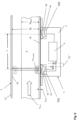
- an apparatus 1 for measuring the flow velocity V med of a fluid 5 in a pipe 2 which is herein after also called flow meter 1, comprises a housing 3 in which a first ultrasonic transducer TD1 and a second ultrasonic transducer TD2 are arranged at a predefined distance L to each other.
- the first ultrasonic transducer TD1 includes a first sound transmitting element 4a and a transmitter/receiver unit 6a which are adapted to emit first ultrasonic pulses P1 at different angles ⁇ 1 .
- the second ultrasonic transducer TD2 is adapted to receive said first ultrasonic pulses P1 and generate a first electronic output signal.
- the second ultrasonic transducer TD2 includes a second sound transmitting element 4b and a second transmitter/receiver unit 6b mounted thereto which are adapted to emit second ultrasonic pulses P2 at different angles ⁇ 2 .
- the first ultrasonic transducer TD1 is adapted to receive said second ultrasonic pulses P2 and generate a second electronic output signal.
- the first and second transducer TD1 and TD2 are connected to a control and evaluation unit 8 which drives both transducers TD1 and TD2 when operated in a transmitting mode and also evaluates the signals received by the transducers, when operated in a receiving mode.
- control and evaluation unit 8 is adapted to vary the angle ⁇ 1 of the ultrasonic pulses P1 which are emitted by the first transducer TD1 when operated in the transmitting mode to an angel which generates a first electronic output signal in the second transducer TD2 that has a maximum amplitude.
- control and evaluation unit 8 is adapted to vary the angle ⁇ 2 of the second ultrasonic pulses which are emitted by the second transducer TD2 when operated in a transmitting mode to an angle which generates an electronic output signal in the first transducer TD1 that has a maximum amplitude.
- the first transducer TD1 of the preferred embodiment of the invention comprises a first transmitter/receiver unit 6a, which is preferably a known piezo actuator and a first wedge shaped element 4a on which the transmitter/receiver unit 6a is mounted at an angle to the outer surface of the pipe.
- the second transducer TD2 includes a second transmitter/receiver unit 6b which is preferably a known piezo actuator and a second wedge shaped element 4b, on which the second transmitter/receiver unit 6a is mounted at an angle inverse to the one of the first wedge shaped element 4a to the outer surface of the pipe wall 12.
- the first and second transducers (TD1, TD2) are identical.
- the first sound transmitting element and/or the second sound transmitting element are wedge shaped elements 4a, 4b as described herein before.
- the wedge shaped elements are preferably plastic wedges or prisms made of e.g. polyurethane, polyamid, polyetherimid or another known plastic material which is able to conduct ultrasonic waves from the transmitter/receiver units 6a, 6b to a contacting area in which the wedge shaped elements 4a, 4b are in contact with the wall 12 of the pipe 2 as shown in Figs 1 and 2 .
- a known ultrasonic gel or a layer of soft plastics, preferably silicone rubber, may be arranged between the wedge shaped elements 4a, 4b and the outer wall surface.
- the ultrasonic waves generated by the transmitter/receiver units 6a, 6b of the first and second transducer TD1, TD2, when operated as an emitter, are diffracted in the sound transmitting elements 4a, 4b and generate vibrations in the wall 12 of the pipe 2 which in turn generate an ultrasonic wave front which is emitted at an angle ⁇ 1 , ⁇ 2 to the inner surface 2a of the pipe 2.
- the angle ⁇ 1 , ⁇ 2 strongly depends on the frequency f1, f2 of the ultrasonic waves which are emitted by the transmitter/receiver units 6a, 6b, so that by tuning the frequency f1, f2 of the transducers (TD1, TD2) over a certain range, e.g. from 100 kHz to 1 MHz, the angel ⁇ 1 , ⁇ 2 of the ultrasonic waves/pulses P1, P2 emitted from the transducers TD1, TD2 into the fluid 5 can be changed.
- the vibrations generated in the wall are typically Lamb waves which can exist in different wave modes having different properties in the interaction with the liquid.
- a preferable mode to be used for the generation of the emitted beam into the fluid is the fundamental asymmetric Lamb wave mode in the wall which is also called A0-mode.
- This asymmetric A0 Lamb wave mode provides for the advantage that it shows a strong interaction with the surrounding liquid and thus emits most of its acoustical energy already along a short travel path into the liquid.
- other known Lamb wave modes with a strong interaction with the liquid may be used.
- the transmitter/receiver units 6a, 6b of the first and second transducer TD1, TD2 can comprise a simple piezoelectric element which is mounted to the wall 12 by means of a sound transmitting element which is configured as a mechanical grating 4' that is located in between the piezoelectric element 6a, 6b and the wall 12, as it is shown in Fig. 8 .
- This grating preferably consists of two different materials, e.g. a first sound-transmitting material like metal and a second non-sound transmitting material like air or plastic, which are arranged in a 1-dimensional or 2-dimensional periodic order.
- the waves/ultrasonic pulses P1, P2 which are generated by the transmitter/receiver units (piezoelectric elements) 6a, 6b can only propagate in one of the materials, e.g. the metal, and are blocked in the other, e.g. the air or plastic, or they propagate with different propagation velocities so that a phase shift of the ultrasonic waves which form the pulses P1, P2 occurs at the wall 12. As applicant has found, this results in a periodical excitation of the acoustic waves in the wall 12, so that only one specific wave front or pulse is emitted at a specific angle ⁇ 1 , ⁇ 2 .
- the angle ⁇ 1 , ⁇ 2 under which the first and second ultrasonic pulses P1, P2 are emitted from the grating 4' into the liquid can be varied, and the angle can be tuned to an angle at which the amplitude of the signal received by the receiving transducer TD2, TD1 has a maximum, as it was set forth herein before with reference to the embodiment in which the sound transmitting elements are configured as wedges 4a, 4b.
- the periodicity is preferably selected in such a way that it fits to the wavelength of the required ultrasonic mode in the wall 12, so that as a result preferably only this mode is excited.
- an electronic grating 104 on the piezoelectric element of the transmitter/receiver units 6a, 6b can be used, in which a periodic electrode structure which comprises two or more nested sets of comb shaped electrodes 105, 106 extending into each other is printed on the outer surface of the piezoelectric element of the transmitter/receiver units 6a, 6b as it is shown in Fig. 9a and 9b .
- the two different sets of electrodes 105, 106 are connected to a frequency tunable signal generator 108, e.g. an AC-power supply which is part of the control and evaluation unit and which can be tuned to a frequency that generates lamb waves in the material of the wall 12.
- the comb shaped arrangement of electrodes 105, 106 also leads to a periodic excitation of acoustic waves in the wall 12 which finally results in ultrasonic pulses P1, P2 that are emitted into the liquid under an angle ⁇ 1 , ⁇ 2 which strongly depends on the frequency of the signals fed to the first and second transmitter/receiver units 6a, 6b.
- a transducer TD1, TD2 which can generate first and second ultrasonic pulses P1, P2 at different emitting angles ⁇ 1 , ⁇ 2
- a plurality of pairs of opposing electrodes 204a, 206b; 204b, 206b; 204c, 206c may be provided on the surface of the piezo electric elements of the transmitter/receiver units 6a, 6b, as it is shown in the exemplary embodiment of Fig. 9 in which 3 pairs of electrodes 204, 206 are shown for demonstrative purposes only.
- Each pair of electrodes 204, 206 is fed by a separate signal generator 208a to 208c with an individual periodic signal having the same frequency but comprising a phase shift.
- the emitting angle ⁇ 1 , ⁇ 2 of the superposed wave front which forms the ultrasonic pulses P1, P2 can be varied at a fixed frequency, as it is e.g. known from ultrasound scanning devices for scanning the human body.
- This embodiment provides for the advantage that the frequency which is fed to the electrodes of the ultrasonic emitter/receiver units 6a, 6b can be set to a desired lamb frequency which fits best for a specific material, and the angle ⁇ 1 , ⁇ 2 can afterwards be varied until the received pulses P1, P2 have a maximum amplitude by altering the phase shift between the pairs of electrodes 204, 206.
- the sound transmitting element may be a known ultrasonic gel or a flat layer of soft plastics 109, preferably silicone rubber as mentioned herein before.
- a further possible variant of a transmitter which is not shown in the drawings may comprise an electromagnetic acoustical transducer (EMAT) in which a more static magnetic field in combination with eddy currents is applied and generated inside the wall material.
- EMAT electromagnetic acoustical transducer
- the interaction between the eddy currents and the magnetic field results in mechanical movements inside the wall which in turn generate ultrasonic waves/pulses propagating in the wall.
- the angle ⁇ 1 of the emitted first pulses P1 is altered until a maximum amplitude signal in transducer TD2 is obtained and the flight time of the pulses P altered is measured by the control and evaluation unit 8.
- the angel ⁇ 1 at which the amplitude of the received signal in the receiving transducer TD2 becomes a maximum is determined by tuning the frequency of the first emitter/receiver unit 6a to a frequency f1 max which generates a maximum signal in the second transducer TD2.
- the angle ⁇ 1 at which the amplitude of the received signal in the receiving transducer TD2 becomes a maximum is determined by tuning the phase between the signals fed to the pairs of electrodes 204a, 206a; 204b, 206b and 204c, 206c by the separate signal generators 208a, 208b and 208c until the signal received by the second Transducer TD2 becomes a maximum.
- the apparatus is operated the other way round as shown in Fig. 2 , in order to measure the flight time T2 of ultrasonic pulses P2 which are emitted by the second transducer TD2 and received by the first transducer TD1.
- the fixed distance L may be obtained by an initial calibration of the apparatus 1 mounted to a known pipe 2 in which a known fluid is streaming with a known speed V med . After calculating and storing the corresponding value L for the (effective distance) from the afore-mentioned mathematical relation in a memory of the micro controller of the control and evaluation unit 8, this effective distance value L may be used for all further applications of the apparatus 1.
- the first transducer TD1 is further driven by the control and evaluation unit 8 to generate lamb waves 10 within the wall material of said pipe 2 having a first frequency f1 lamb .
- the lamb waves which are only schematically indicated in Fig. 3 for illustration purposes propagate inside the wall material and are received by the second transducer TD2.
- the second transducer TD2 which is operated in a receiving mode receives the lamb waves 10 and generates an electronic signal having a frequency f1 lamb which is transmitted to the control and evaluation unit 8.
- the first transducer TD1 is further driven in a transmitting/receiving mode in which the transmitter/receiver unit 6a is first operated as a transmitter and transmits a short pulse P1 of the afore-mentioned lamb waves 10 of a known first frequency f1 lamb .
- the first transducer TD1 is switched to the receiving mode in which the transmitter/receiver unit 6a is operated as a receiver which receives the lamb waves 10 which are travelling around the perimeter U of the pipe 2 in the pipe wall 12 .
- the perimeter U and the diameter D are not the exact perimeter /diameter values of the pipe, but are averaged values of the perimeter/diameter measured at about half way of the wall thickness.
- the apparatus according to the invention has the advantage that all of the afore-mentioned parameters can be measured without knowing any details about the pipe parameters itself which makes the apparatus highly flexible and allows the device to be used as a mobile, preferably also hand held clamp-on device for different kind of measuring applications.
- lamb wave modes with a low interaction with the surrounded liquid are used as e.g. the fundamental symmetric Lamb wave mode (so called SO-mode).
- the housing 3 of the apparatus 1 is adapted to be preferably releasable mounted at the bottom surface of a pipe 2, e.g. by means of holding flanges and straps (not shown) wrapped around the pipe or by magnets or releasable glue or the like.
- the apparatus 1 is operated similar to the embodiment of Fig. 3 for measuring the diameter D of the pipe 2 which is completely filled.
- the first transducer TD1 may be configured and controlled by the control and evaluation unit 8 to generate first ultrasonic pulses P1 parallel which are emitted in a direction parallel to the diameter D of the pipe 2 and receive reflections of the emitted ultrasonic pulses P1 parallel which are reflected at an adjacent inner wall surface 2a (not shown in detail) and/or at an upper surface 5a of the fluid 5 in a partially filled pipe 2 and/or at the inner wall surface 2a of the pipe 2 which is located opposite to said first transducer TD1, as shown in Fig. 6 .
- the second ultrasonic transducer TD2 may be employed instead of using the first transducer TD1 for generating the lamb waves 10 and ultrasonic pulses P1 parallel .
- the ultrasonic pulses P1 parallel are generated and received by the first transducer TD1 and the lamb waves 10 running through the wall 2 for measuring the sonic speed in the wall material are generated in the same configuration by the second transducer TD2 and vice versa.
- This provides for the advantage of an increased measuring speed and a shortened measuring time or even an improved measuring accuracy when repeating the measurements several time and calculating an average value from a series of measured single values.
- a method of measuring the flow velocity V med of a fluid 5 in a pipe 2 comprises the following steps:
- the method comprises the further method steps of
- the above-described method may comprise the further method steps of
- the diameter obtained from a runtime measurement of lamb waves 10 running in the wall 12 of the pipe may be used to calculate whether a pipe 2 is completely or only partially filled with a liquid medium 5.
- the control and evaluation unit 8 calculates if the measured diameter D or Di is equal to H fluid or not. If the measured value of H fluid is smaller than D or D i the pipe 2 is only partially filled.
- the values and parameters which can be measured with the apparatus 1 may be displayed on a display mounted to or included in the housing 3 and/or stored in the memory of the control and evaluation unit 8 and/or may be transmitted to a remote server or central control unit (not shown), e.g. via a known data communication network.
Description
- The invention is related to an apparatus and a method for measuring the flow velocity of a fluid in a pipe. The invention and its scope of protection is defined in the appended independent claims. In an aspect, there is provided an apparatus for measuring the flow velocity (Vmed) of a fluid in a pipe having a circular cross section as defined in appended
claim 1. In an aspect, there is provided a method for measuring the flow velocity (Vmed) of a fluid in a pipe having a circular cross section as defined in appendedclaim 5. - Ultrasonic flow meters are commonly used for measuring the volume flow of different fluid media in many industrial applications. Especially clamp-on ultrasonic flow meters are very convenient and flexible to use because they can be mounted without opening the pipe and without interruption of the process.
- For mounting clamp-on ultrasonic flow meters, two transducers for emitting and receiving ultrasonic signals are mounted on outer surface of the pipe. The transducers are emitting ultrasonic signals under a fixed angle through the pipe. To do so, the transducers are arranged on the same side of the pipe at such a distance to each other that the second transducer receives the signal emitted by the first transducer and reflected at the opposite pipe wall and vice versa. Also variants exist were the transducers are arranged on opposite sides of a pipe but in a certain distance along the pipe axis and the signal transmitted straight through the pipe is detected. This avoids signal losses due to the reflection but generates a higher installation effort. The measurement principle for both configurations is the same.
- Due to the emitting of the sound under a fixed angle, the transducers have to be arranged in a specific way which is determined by the emitted beam angle and the dimension of the pipe, in particular the pipe diameter and the wall thickness. These parameters are varying strongly from pipe to pipe and are not known a priori. Therefore, the transducers cannot be arranged in fixed installations already during the production process but have to be manually adjusted on-site by the user. This generates a high effort for the user during the sensor installation. Also a wrong mounting of the transducers can result in significant measurement errors of the sensor or even a failure of the sensor operation. Due to these requirements and problems during the sensor installation, clamp-on flow meters gained a low reputation although they provide the advantage of a non-intrusive mounting and operation of the sensor.
- To gain a strong signal of an ultrasonic flow meter which is of great importance for obtaining a high accuracy of the measurements carried out afterwards, it is of advantage to focus the ultrasonic beam as good as possible onto the second transducer, in order to lose as less as possible of the signal. However, a precise focusing of the transmitter and receiver requires an even higher accuracy of the positioning of the transmitter and receiver during sensor installation.
-
US2016/305805A1 describes that an ultrasonic flowmeter includes a conduit for receiving a flow of a fluid and a flexible printed circuit board including: a pair of ultrasonic transducers, wherein each transducer comprises a piezoelectric element divided into a plurality of segment electrodes and the flexible printed circuit board is bonded around the conduit; and a control circuit configured to sequentially activate the segment electrodes using a pulse train to cause at least one of the piezoelectric elements to emit a sonic signal. A delay time between activation of each successive segment electrode controls a phase velocity and an angle of emission of the corresponding sonic signal. -
US2015/160053A1 describes that an ultrasonic transducer includes: a piezoelectric element divided into a plurality of segments; a pulse generator configured to generate a pulse signal that comprises pulses of a certain frequency; and a control circuit that sequentially activates the segments to cause the element to emit a sonic signal, where a controlled delay time between activation of each segment varies the emission angle of the sonic signal so as to compensate for angle changes caused by either changes in Beam refraction or due to Beam Blowing caused by high flow velocity. -
US2012/271568A1 describes a method and apparatus utilizing a pair of ultrasonic transducers simultaneously transmitting and receiving to measure the mean time of flight of an ultrasonic signal over a given distance, and thereby the speed of sound of a fluid in a conduit at a given temperature, independent of flow rate, and the flow rate of the fluid. A signal source simultaneously drives an upstream transducer and a downstream transducer, each of which receive the signal transmitted by the other. The difference between the upstream and downstream signals is substantially invariant with rate of flow of the fluid, and measurement of parameters of this signal takes into account the speed of sound of the fluid. The time of flight for the upstream and downstream signals can then be used to calculate the flow rate. A phase locked loop providing feedback from the received signals to the signal source is utilized to maintain a predetermined number of cycles of the difference signal between the transducers, thereby automatically adjusting for variations of the speed of sound in the fluid in response to temperature changes. - Moreover, a further problem of the known prior art clamp-on flow meters can be seen in that the beam angle is changed by different flow rates of the medium flowing inside the pipe. Therefore, the focusing of the beam is limited to an area which is large enough to allow the flow sensor to operate under all conditions. In other words, the focusing area of the known clamp-on fixed beam angle flow meters has to be large enough to cover all flow rates speeds which the medium flowing through the pipe may have.
- To avoid the change of the beam angle by the flow rate,
EP 3 1 15 753 A1 - Although
EP 3 115 753 A1 discloses transmitters/transducers for generating an ultrasonic beam which is emitted at a variable beam angle into a vessel, the document is silent about measuring the height of a liquid or the volume flow of a liquid flowing through a pipe having a circular cross section with a high precision in a simple way without knowing the diameter and the wall thickness of the pipe, as well as the properties of the liquid. - Accordingly, it is a problem of the present invention to provide an apparatus which allows a non-intrusive measurement of the flow velocity, the volume flow and the filling height of a fluid running through a pipe having an unknown diameter.
- This problem is solved by an apparatus as claimed in claims 1-4.
- Moreover, it is a further problem of the present invention to provide for a method which allows a quick and easy non-intrusive determination of the flow velocity, the diameter and the volume flow as well as the filling height of a fluid in a pipe having an unknown diameter or radius.
- This problem is solved by a method as claimed in claims 5-8.
- Further objects of the present invention are included in the dependent claims.
- The invention is hereinafter described with reference to the accompanying drawings.
- In the drawings
- Fig. 1
- is a schematic side view of a completely filled pipe in which a fluid is streaming with a clamp-on apparatus according to the present invention in which first ultrasonic pulses are emitted by a first transducer which are received by a second transducer,
- Fig. 2
- is the pipe of
Fig. 1 in which second ultrasonic pulses are emitted by the second transducer which are received by the first transducer, in order to illustrate the general principle of measuring the speed of the fluid and the volume flow with the apparatus, - Fig. 3
- is a schematic view of the pipe of the arrangement of
Fig. 1 and2 , in which the first transducer generates lamb waves running inside the pipe wall which are received by the second transducer, and alternatively by the first transducer, in order to determine the sonic speed of the lamb waves in the wall material and the perimeter and average diameter of the pipe, - Fig. 4
- is a schematic view of a further measuring configuration similar to the one of
Fig. 3 in which the apparatus according to the invention is mounted to the bottom of a partially filled pipe when measuring the sonic speed of lamb waves in the wall material and afterwards the perimeter of the pipe, - Fig. 5
- is a schematic illustration of the configuration of
Fig. 4 when measuring the height of the fluid in the pipe on basis of reflections of ultrasonic pulses emitted by one of the transducers in parallel to the diameter of the pipe and reflected at the fluid surface, - Fig. 6
- is a schematic view of the configuration of
Fig. 5 when measuring the inner diameter of the pipe on basis of reflections of ultrasonic pulses emitted by one of the transducers in parallel to the diameter of the pipe which are reflected at the opposite inner surface of the pipe, - Fig. 7
- is a schematic more detailed view of the working principle of the transducers used in the apparatus according to the present invention,
- Fig. 8
- is a schematic side view of a transmitter/receiver unit in which the sound transmitting element is configured as a mechanical grating,
- Fig. 9a
- is a schematic side view of a transmitter/receiver unit in which the sound transmitting element is configured as an electronical grating which is arranged on the piezo electric element of the transmitter/receiver unit,
- Fig. 9b
- is a schematic top view of a transmitter/receiver unit of
Fig. 9a , and - Fig. 10
- is a schematic side view of a further embodiment of a transmitter/receiver unit in which the sound transmitting element is configured as an arrangement of opposing electrodes which are independently connected to separate signal generators which can be driven so as to generate ultrasonic waves of substantially the same frequency having a phase shift.
- As it is shown in
Figs. 1 to 6 , anapparatus 1 for measuring the flow velocity Vmed of afluid 5 in apipe 2 which is herein after also calledflow meter 1, comprises ahousing 3 in which a first ultrasonic transducer TD1 and a second ultrasonic transducer TD2 are arranged at a predefined distance L to each other. The first ultrasonic transducer TD1 includes a firstsound transmitting element 4a and a transmitter/receiver unit 6a which are adapted to emit first ultrasonic pulses P1 at different angles α1. The second ultrasonic transducer TD2 is adapted to receive said first ultrasonic pulses P1 and generate a first electronic output signal. In the same way, the second ultrasonic transducer TD2 includes a secondsound transmitting element 4b and a second transmitter/receiver unit 6b mounted thereto which are adapted to emit second ultrasonic pulses P2 at different angles α2.The first ultrasonic transducer TD1 is adapted to receive said second ultrasonic pulses P2 and generate a second electronic output signal. The first and second transducer TD1 and TD2 are connected to a control andevaluation unit 8 which drives both transducers TD1 and TD2 when operated in a transmitting mode and also evaluates the signals received by the transducers, when operated in a receiving mode. - As it is shown in
Fig. 1 , the control andevaluation unit 8 is adapted to vary the angle α1 of the ultrasonic pulses P1 which are emitted by the first transducer TD1 when operated in the transmitting mode to an angel which generates a first electronic output signal in the second transducer TD2 that has a maximum amplitude. - In the same way, the control and
evaluation unit 8 is adapted to vary the angle α2 of the second ultrasonic pulses which are emitted by the second transducer TD2 when operated in a transmitting mode to an angle which generates an electronic output signal in the first transducer TD1 that has a maximum amplitude. - As it is shown in
Figs. 1 ,2 and7 , the first transducer TD1 of the preferred embodiment of the invention comprises a first transmitter/receiver unit 6a, which is preferably a known piezo actuator and a first wedge shapedelement 4a on which the transmitter/receiver unit 6a is mounted at an angle to the outer surface of the pipe. In the same way, the second transducer TD2 includes a second transmitter/receiver unit 6b which is preferably a known piezo actuator and a second wedge shapedelement 4b, on which the second transmitter/receiver unit 6a is mounted at an angle inverse to the one of the first wedge shapedelement 4a to the outer surface of thepipe wall 12. In the preferred embodiment of the invention, the first and second transducers (TD1, TD2) are identical. - In the preferred embodiment of the invention, the first sound transmitting element and/or the second sound transmitting element are wedge shaped
elements receiver units elements wall 12 of thepipe 2 as shown inFigs 1 and2 . In order to improve the transmission of sound ultrasonic vibrations between the wedge shapedelements wall 12 of thepipe 2, a known ultrasonic gel or a layer of soft plastics, preferably silicone rubber, may be arranged between the wedge shapedelements - As it is further indicated in
Fig. 7 , the ultrasonic waves generated by the transmitter/receiver units sound transmitting elements wall 12 of thepipe 2 which in turn generate an ultrasonic wave front which is emitted at an angle α1, α2 to theinner surface 2a of thepipe 2. Due to the frequency dependency of the sonic speed in the wall material of the pipe, which is usually metal/steel, the angle α1, α2 strongly depends on the frequency f1, f2 of the ultrasonic waves which are emitted by the transmitter/receiver units fluid 5 can be changed. - The vibrations generated in the wall are typically Lamb waves which can exist in different wave modes having different properties in the interaction with the liquid. A preferable mode to be used for the generation of the emitted beam into the fluid is the fundamental asymmetric Lamb wave mode in the wall which is also called A0-mode. This asymmetric A0 Lamb wave mode provides for the advantage that it shows a strong interaction with the surrounding liquid and thus emits most of its acoustical energy already along a short travel path into the liquid. Alternatively, also other known Lamb wave modes with a strong interaction with the liquid may be used.
- According to an alternative embodiment of the invention, the transmitter/
receiver units wall 12 by means of a sound transmitting element which is configured as a mechanical grating 4' that is located in between thepiezoelectric element wall 12, as it is shown inFig. 8 . This grating preferably consists of two different materials, e.g. a first sound-transmitting material like metal and a second non-sound transmitting material like air or plastic, which are arranged in a 1-dimensional or 2-dimensional periodic order. Due to the grating 4' the waves/ultrasonic pulses P1, P2 which are generated by the transmitter/receiver units (piezoelectric elements) 6a, 6b can only propagate in one of the materials, e.g. the metal, and are blocked in the other, e.g. the air or plastic, or they propagate with different propagation velocities so that a phase shift of the ultrasonic waves which form the pulses P1, P2 occurs at thewall 12. As applicant has found, this results in a periodical excitation of the acoustic waves in thewall 12, so that only one specific wave front or pulse is emitted at a specific angle α1, α2. By tuning the frequency f1, f2 of the transducers (TD1, TD2) over a certain frequency range, the angle α1, α2 under which the first and second ultrasonic pulses P1, P2 are emitted from the grating 4' into the liquid can be varied, and the angle can be tuned to an angle at which the amplitude of the signal received by the receiving transducer TD2, TD1 has a maximum, as it was set forth herein before with reference to the embodiment in which the sound transmitting elements are configured aswedges wall 12, so that as a result preferably only this mode is excited. - As a further alternative embodiment to the mechanical grating 4', an
electronic grating 104 on the piezoelectric element of the transmitter/receiver units electrodes receiver units Fig. 9a and9b . The two different sets ofelectrodes tunable signal generator 108, e.g. an AC-power supply which is part of the control and evaluation unit and which can be tuned to a frequency that generates lamb waves in the material of thewall 12. As applicant has found, the comb shaped arrangement ofelectrodes wall 12 which finally results in ultrasonic pulses P1, P2 that are emitted into the liquid under an angle α1, α2 which strongly depends on the frequency of the signals fed to the first and second transmitter/receiver units - As an even further alternative embodiment for a transducer TD1, TD2 which can generate first and second ultrasonic pulses P1, P2 at different emitting angles α1, α2, a plurality of pairs of opposing
electrodes receiver units Fig. 9 in which 3 pairs of electrodes 204, 206 are shown for demonstrative purposes only. Each pair of electrodes 204, 206 is fed by aseparate signal generator 208a to 208c with an individual periodic signal having the same frequency but comprising a phase shift. By tuning the frequency of thesignal generators 208a to 208c to a desired lamb frequency and afterwards varying the phase shift between adjacent sets of electrodes, the emitting angle α1, α2 of the superposed wave front which forms the ultrasonic pulses P1, P2 can be varied at a fixed frequency, as it is e.g. known from ultrasound scanning devices for scanning the human body. This embodiment provides for the advantage that the frequency which is fed to the electrodes of the ultrasonic emitter/receiver units - In the afore described embodiments of
Figs. 9 and10 , the sound transmitting element may be a known ultrasonic gel or a flat layer ofsoft plastics 109, preferably silicone rubber as mentioned herein before. - A further possible variant of a transmitter which is not shown in the drawings may comprise an electromagnetic acoustical transducer (EMAT) in which a more static magnetic field in combination with eddy currents is applied and generated inside the wall material. The interaction between the eddy currents and the magnetic field results in mechanical movements inside the wall which in turn generate ultrasonic waves/pulses propagating in the wall. With this alternative embodiment, a contactless excitation of mechanical waves can be obtained.
- Now the embodiments of the method and apparatus of the present invention are described in more detail with regard to
Figs. 1 to 7 . - In order to measure the flight time T1 of the first pulses P1 emitted by the first transducer TD1 the angle α1 of the emitted first pulses P1 is altered until a maximum amplitude signal in transducer TD2 is obtained and the flight time of the pulses P altered is measured by the control and
evaluation unit 8. In the embodiments of the invention using a transmitter/receiver unit Figs. 1 to 9 , the angel α1 at which the amplitude of the received signal in the receiving transducer TD2 becomes a maximum is determined by tuning the frequency of the first emitter/receiver unit 6a to a frequency f1max which generates a maximum signal in the second transducer TD2. In the embodiment ofFig. 10 , the angle α1 at which the amplitude of the received signal in the receiving transducer TD2 becomes a maximum is determined by tuning the phase between the signals fed to the pairs ofelectrodes separate signal generators - Afterwards, the apparatus is operated the other way round as shown in
Fig. 2 , in order to measure the flight time T2 of ultrasonic pulses P2 which are emitted by the second transducer TD2 and received by the first transducer TD1. - From the known fixed distance between the first transducer TD2 and the second transducer TD2 and the measured flight times T1 and T2 which are different if the
fluids 5 is streaming through thepipe 2 with a velocity Vmed , the control andevaluations unit 8, which may include a known micro controller and adapted control software, calculates the speed Vmed of thefluid 5 in thepipe 2 as
- In order to account for different travelling lengths of the sonic pulses P1, P2 in the wedge shaped
elements apparatus 1 mounted to a knownpipe 2 in which a known fluid is streaming with a known speed Vmed . After calculating and storing the corresponding value L for the (effective distance) from the afore-mentioned mathematical relation in a memory of the micro controller of the control andevaluation unit 8, this effective distance value L may be used for all further applications of theapparatus 1. - According to the claimed invention which is shown in
Fig. 3 , the first transducer TD1 is further driven by the control andevaluation unit 8 to generatelamb waves 10 within the wall material of saidpipe 2 having a first frequency f1lamb . The lamb waves, which are only schematically indicated inFig. 3 for illustration purposes propagate inside the wall material and are received by the second transducer TD2. The second transducer TD2 which is operated in a receiving mode receives the lamb waves 10 and generates an electronic signal having a frequency f1lamb which is transmitted to the control andevaluation unit 8. From the flight time TflightTD1-TD2 of the lamb waves 10 travelling in thewall 12 from the first transducer TD1 to the second transducer TD2, the control andevaluation unit 8 calculates the sonic speed C(f1lamb) of said lamb waves 10 to
evaluation unit 8 in the same way as all other parameters measured. - According to the claimed invention, the first transducer TD1 is further driven in a transmitting/receiving mode in which the transmitter/
receiver unit 6a is first operated as a transmitter and transmits a short pulse P1 of the afore-mentioned lamb waves 10 of a known first frequency f1lamb . Immediately after sending out the short Pulse P1, the first transducer TD1 is switched to the receiving mode in which the transmitter/receiver unit 6a is operated as a receiver which receives the lamb waves 10 which are travelling around the perimeter U of thepipe 2 in thepipe wall 12 . - From the flight time Tflight lamb TD1-TD1 of the lamb waves 10 emitted from and received by the first transducer TD1 and preferably the stored value of the sonic speed C(f1lamb) of said lamb waves 10 measured before, the control and
evaluation unit 8 calculates the perimeter U of saidpipe 2 as

evaluation unit 8. In this respect, it should be noted that the perimeter U and the diameter D are not the exact perimeter /diameter values of the pipe, but are averaged values of the perimeter/diameter measured at about half way of the wall thickness. - According to a yet further embodiment of the invention the control and
evaluation unit 8 determines the volume flow J of thefluid 5 running through thepipe 2 from the measured and stored values of the speed Vmed of thefluid 5 and diameter D of thepipe 2 as
- According to another object of the present invention, the control and
evaluation unit 8 is further adapted to determine the sonic speed Cmed in thefluid 5 which might be used to identify an unknown fluid or alternatively to determine if the composition of a mixture of two or moredifferent fluids 5 running through thepipe 2 has changed or not. To do so, the control andevaluation unit 8 calculates preferably from measured and stored values of the flight times T1 and T2 and diameter or perimeter the sonic speed to

- Although the perimeter U and the diameter D may also be known values for a pipe, the apparatus according to the invention has the advantage that all of the afore-mentioned parameters can be measured without knowing any details about the pipe parameters itself which makes the apparatus highly flexible and allows the device to be used as a mobile, preferably also hand held clamp-on device for different kind of measuring applications.
- For these described operation modes an emitting of the acoustical energy into the liquid is, in contrast to the flow speed measurement, of disadvantage. Thus, preferably lamb wave modes with a low interaction with the surrounded liquid are used as e.g. the fundamental symmetric Lamb wave mode (so called SO-mode).
- According to a further embodiment of the invention which is illustrated in
Fig. 4 , thehousing 3 of theapparatus 1 is adapted to be preferably releasable mounted at the bottom surface of apipe 2, e.g. by means of holding flanges and straps (not shown) wrapped around the pipe or by magnets or releasable glue or the like. In this application, theapparatus 1 is operated similar to the embodiment ofFig. 3 for measuring the diameter D of thepipe 2 which is completely filled. - As it is further shown in
Fig. 5 , the first transducer TD1 may be configured and controlled by the control andevaluation unit 8 to generate first ultrasonic pulses P1 parallel which are emitted in a direction parallel to the diameter D of thepipe 2 and receive reflections of the emitted ultrasonic pulses P1 parallel which are reflected at an adjacentinner wall surface 2a (not shown in detail) and/or at an upper surface 5a of thefluid 5 in a partially filledpipe 2 and/or at theinner wall surface 2a of thepipe 2 which is located opposite to said first transducer TD1, as shown inFig. 6 . - In this measuring application, the control and
evaluation unit 8 is further adapted to calculate from the flight time T1', T1" and T1‴ of the reflected ultrasonic pulses P1parallel which are received by said first transducer TD1 the wall thickness dwall of thepipe 2 and/or the filling height Hfluid of thefluid 5 in a partially filledpipe 2 and/or the inner diameter Di of thepipe 2 according to the following relations:


- T1'
- is the flight time of the first ultrasonic pulses P1 parallel emitted and received by the first transducer TD1 which are reflected at the
inner surface 2a of the pipe wall on the side of thepipe 2 which is opposite of the first transducer TD1, - T1"
- is the flight time of the first ultrasonic pulses P1parallel emitted and received by the first transducer TD1 which are reflected at a surface 5a of the
fluid 5 in a partially filledpipe 2, - T1‴
- is the flight time of the first ultrasonic pulses P1 parallel emitted and received by the first transducer TD1 which are reflected at the adjacent
inner surface 2a of the pipe wall, - Di
- is the inner diameter of the
pipe 2, - Cmed
- is the sonic speed of the first ultrasonic pulses P1 parallel in the
fluid 5 which are determined similar to the embodiment ofFig. 3 and4 as

- Cwall
- is the sonic speed of the first ultrasonic pulses P1parallel in the wall material which are emitted by the first transducer TD1 in a direction parallel to the diameter D of the
pipe 2 which is previously measured as set forth above with regard to the embodiment ofFig. 3 . - With regard to the embodiments described herein before, it should be in the scope of the invention that instead of using the first transducer TD1 for generating the lamb waves 10 and ultrasonic pulses P1 parallel, also the second ultrasonic transducer TD2 may be employed. This may also include that the ultrasonic pulses P1parallel are generated and received by the first transducer TD1 and the lamb waves 10 running through the
wall 2 for measuring the sonic speed in the wall material are generated in the same configuration by the second transducer TD2 and vice versa. This provides for the advantage of an increased measuring speed and a shortened measuring time or even an improved measuring accuracy when repeating the measurements several time and calculating an average value from a series of measured single values. - According to another object of the present invention, a method of measuring the flow velocity Vmed of a
fluid 5 in apipe 2 comprises the following steps: - attaching an
apparatus 1 as described herein before to the outer surface of a linear section of the pipe and aligning thehousing 3 such that the predefined distance L between said first and second transducer TD1, TD2 extends in parallel to the longitudinal axis of a linear section of thepipe 2, - tuning the first transducer TD1 to an angle which generates a second electronic output signal of a maximum amplitude in said second transducer TD2, preferably by tuning the frequency of the first transducer TD1and measuring the amplitude of the output signal of the second transducer TD2,
- measuring the flight time T1 of first ultrasonic pulses P1 travelling from the first transducer TD1 to the second transducer TD2 and measuring the flight time T2 of second ultrasonic pulses P2 travelling from the second transducer TD2 to the first transducer TD1, and
- calculating the speed Vmed of the
fluid 5 running through thepipe 2 as
- In accordance with the claimed invention the method is characterized by the further method steps of
- tuning said first transducer TD1 to a first frequency which generates lamb waves 10 within the wall material of said
pipe 2 having a first frequency f1lamb, - measuring the flight time Tflight TD1-TD2 of the lamb waves 10 between the first transducer TD1 and the second transducer TD2 and calculating the sonic speed C(f1lamb) of said lamb waves 10 within said wall material as

- Pursuant to the claimed invention, the method comprises the further method steps of
- tuning said first transducer TD1 to generate
lamb waves 10 having said first frequency f1lamb, - interrupting the generation of said lamb waves 10,
- running said first transducer TD1 in a receiver mode and measuring the flight time Tflight lamb TD1-TD1 of the lamb waves 10 emitted from and received by said first transducer TD1 and calculating the perimeter of the pipe as

pipe 2 as
fluid 5 in saidpipe 2 as
- Moreover, the above-described method may comprise the further method steps of
- mounting the
housing 3 at the bottom of thepipe 2, - tuning the first transducer TD1 to generate first ultrasonic pulses P1 parallel which are emitted in a direction parallel to the diameter D of the
pipe 2, - interrupting the generation of the ultrasonic pulses P1 parallel,
- running the first transducer TD1 in a receiver mode and measuring the flight time T1' of ultrasonic pulses P1 parallel which are reflected at an
inner wall surface 2a of thepipe 2 which is adjacent the first transducer TD1 and - calculating the wall thickness of the
pipe 2 as
- running the first transducer TD1 in a receiver mode and measuring the flight time T1" of ultrasonic pulses P1parallel which are reflected at an upper surface 5a of the
fluid 5 in a partially filledpipe 2 and calculating the filling height of the fluid as

- running the first transducer TD1 in a receiver mode and measuring the flight time T1‴ of ultrasonic pulses P1parallel which are reflected at said
inner wall surface 2a of saidpipe 2 which is located opposite to said first transducer TD1 and calculating the inner diameter Di of said pipe as

- Moreover, in the embodiment of the invention in which the
apparatus 1 is mounted at the bottom of thepipe 2, the diameter obtained from a runtime measurement of lamb waves 10 running in thewall 12 of the pipe may be used to calculate whether apipe 2 is completely or only partially filled with aliquid medium 5. To do so, the control andevaluation unit 8 calculates if the measured diameter D or Di is equal to Hfluid or not. If the measured value of Hfluid is smaller than D or Di thepipe 2 is only partially filled. - The values and parameters which can be measured with the
apparatus 1 may be displayed on a display mounted to or included in thehousing 3 and/or stored in the memory of the control andevaluation unit 8 and/or may be transmitted to a remote server or central control unit (not shown), e.g. via a known data communication network. -
- 1
- Apparatus according to the invention
- 2
- pipe
- 2a
- inner surface of pipe
- 3
- housing
- 4a
- first sound transmitting element
- 4b
- second sound transmitting element
- 4'
- mechanical grating
- 5
- fluid
- 5a
- surface of the fluid
- 6a
- transmitter/receiver unit of first transducer
- 6b
- transmitter/receiver unit of second transducer
- 8
- control and evaluation unit
- 10
- lamb waves
- 12
- pipe wall
- 104
- electronic grating
- 105
- comb shaped electrode,
- 106
- comb shaped electrode
- 108
- frequency tunable signal generator
- 109
- sound transmitting element
- 204a,b,c
- electrodes in embodiment of
Fig. 9 - 206a,b,c
- electrodes in embodiment of
Fig. 9 - 208a
- signal generator connected to first pair of
electrodes - 208b
- signal generator connected to second pair of
electrodes - 208c
- signal generator connected to third pair of
electrodes - J
- volume flow
- TD1
- first ultrasonic transducer
- TD2
- second ultrasonic transducer
- L
- predefined distance
- P1
- first ultrasonic pulses
- P2
- second ultrasonic pulses
- α1
- angel at which first pules are emitted
- α2
- angel at which second pules are emitted
- f1max
- tuning frequency of first transducer for maximum pulses in second transducer
- f2max
- tuning frequency of second transducer for maximum pulses in first transducer
- Vmed
- speed of fluid in pipe
- T1
- flight time of first ultrasonic pulses P1
- T2
- flight time of second ultrasonic pulses P2
- f1lamb
- frequency of lamb waves emitted by first transducer
- C(f1lamb)
- sonic speed of lamb waves in wall
- Tflight TD1 - TD1
- flight time of lamb waves emitted and received by first transducer
- Tflight TD1 - TD2
- flight time of lamb waves between first and second transducer
- U
- perimeter of pipe
- D
- diameter of pipe
- P1 parallel
- ultrasonic pulses emitted by first transducer parallel to diameter
- Di
- inner diameter of pipe
- dwall
- thickness of wall
- Hfluid
- height of fluid in partially filled pipe
- T1'
- flight time of first ultrasonic pulses P1 parallel reflected at inner surface of pipe wall
- T1"
- flight time of ultrasonic pulses P1 parallel reflected at surface of fluid
- T1‴
- flight time of pulses P1 parallel reflected at opposite pipe wall
- Cmed
- sonic speed of pulses P1 parallel in fluid
- Cwall
- sonic speed of pulses P1 parallel in wall
Claims (8)
- Apparatus (1) for measuring the flow velocity (Vmed) of a fluid (5) in a pipe (2) having a circular cross section, comprising a housing (3) in which a first ultrasonic transducer (TD1 ) and a second ultrasonic transducer (TD2) are arranged at a predefined effective distance (L) to each other, wherein said first ultrasonic transducer (TD1 ) includes a first sound transmitting element (4a) and a transmitter/receiver unit (6a) mounted thereto which are adapted to emit first ultrasonic pulses (P1 ) at different angles in the fluid and said second ultrasonic transducer (TD2) is adapted to receive said first ultrasonic pulses (P1 ) and generate a first electronic output signal, and wherein the second ultrasonic transducer (TD2) includes a second sound transmitting element (4b) and a transmitter/receiver unit (6b) mounted thereto which are adapted to emit second ultrasonic pulses (P2) at different angles in the fluid, and wherein said first ultrasonic transducer (TD1 ) is adapted to receive said second ultrasonic pulses (P2) and generate a second electronic output signal, a control and evaluation unit (8) electrically coupled to said first and second transducers (TD1, TD2), wherein said control and evaluation unit (8) is adapted to tune the first transducer (TD1 ) to vary the angle of the first ultrasonic pulses (P1) to an angle that generates a first electronic output signal in the second transducer (TD2) of a maximum amplitude, and tune the second transducer (TD2) to vary the angle of the second ultrasonic pulses (P2) to an angle that generates a second electronic output signal in the first transducer (TD1) of a maximum amplitude, and wherein the control and evaluation unit (8) is adapted to measure the flight time (T1 ) of the first ultrasonic pulses (P1 ) in the fluid from the first ultrasonic transducer (TD1) to the second ultrasonic transducer (TD2) and the time of flight (T2) of the second ultrasonic pulses (P2) in the fluid from the second ultrasonic transducer (TD2) to the first ultrasonic transducer (TD1); and wherein the control and evaluation unit is configured to determine a flow velocity of the fluid in the pipe on the basis of the predefined effective distance (L) and the flight time (T1 ) of the first ultrasonic pulses (P1 ) in the fluid from the first ultrasonic transducer (TD1) to the second ultrasonic transducer (TD2) and the time of flight (T2) of the second ultrasonic pulses (P2) in the fluid from the second ultrasonic transducer (TD2) to the first ultrasonic transducer (TD1);characterized in that the first ultrasonic transducer (TD1) is further configured to generate lamb waves in a wall (12) of the pipe, wherein the lamb waves are emitted at least in a length direction of the pipe and in a circumferential direction of the pipe, and wherein the second ultrasonic transducer (TD2) is configured to receive the lamb waves emitted in the length direction of the pipe, and wherein the control and evaluation unit (8) is configured to measure a flight time (T flight TD1-TD2) of the lamb waves in the wall (12) between the first ultrasonic transducer (TD1) and the second ultrasonic transducer (TD2), and wherein the control and evaluation unit (8) is configured to determine a sonic speed (Cf1lamb) of the lamb waves on the basis of the flight time (T flight TD1-TD2) of the lamb waves in the wall (12) between the first ultrasonic transducer (TD1) and the second ultrasonic transducer (TD2);and in that the first ultrasonic transducer (TD1) is further configured to receive the lamb waves emitted in the circumferential direction of the pipe, and wherein the control and evaluation unit (8) is configured to measure a flight time (T flight TD1-TD1) of the lamb waves travelling around a perimeter of the pipe (2) in the pipe wall (12) from the first ultrasonic transducer (TD1) and back to the first ultrasonic transducer (TD1); andwherein, the control and evaluation unit (8) is configured to determine a length (U) of the perimeter of the pipe on the basis of sonic speed of the lamb waves (Cf1lamb) and the flight time (T flight TD1-TD1) of the lamb waves travelling around the perimeter of the pipe (2) in the pipe wall (12) from the first ultrasonic transducer (TD1) and back to the first ultrasonic transducer (TD1); andin that the control and evaluation unit is configured to determine a volume flow of the fluid in the pipe on the basis of flow velocity of the fluid in the pipe and the length of the perimeter of the pipe.
- Apparatus as claimed in claim 1,
wherein,
the housing (3) is adapted to be mounted on the bottom of said pipe (2) and that first transducer (TD1 ) is further adapted to generate first ultrasonic pulses (P1 parallel) which are emitted in a direction parallel to the diameter (D) of said pipe (2), and said first transducer (TD1) is further adapted to receive reflections of said emitted ultrasonic pulses (P1 parallel) which are reflected at an adjacent inner wall surface (2a) of said pipe and/or at an upper surface (5a) of said fluid (5) in a partially filled pipe (2) and/or at said inner wall surface (2a) of said pipe (2) which is located opposite to said first transducer (TD1), and wherein said control and evaluation unit (8) is further adapted to determine from the flight time (T1'), (T1") and (T1‴) of the reflected ultrasonic pulses (P1 parallel) received by said first transducer (TD1 ) the wall thickness (dwall) of said pipe (2) and/or the filling height (Hfluid) of a fluid (5) in a partially filled pipe (2) and/or the inner Diameter (Di) of said pipe (2) according to the following relations:

 T1' is the flight time of the first ultrasonic pulses (P1 parallel) emitted and received by the first transducer (TD1 ) which are reflected at the inner surface (2a) of the pipe wall on the side of the pipe (2) which is opposite of the first transducer (TD1 ),T1" is the flight time of the first ultrasonic pulses (P1 parallel) emitted and received by the first transducer (TD1) which are reflected at a surface (5a) of the fluid (5) in a partially filled pipe (2),T1‴ is the flight time of the first ultrasonic pulses (P1 parallel) emitted and received by the first transducer (TD1 ) which are reflected at the adjacent inner surface (2a) of the pipe wall,Di is the inner diameter of the pipe (2),Cmed is the sonic speed of the first ultrasonic pulses (P1 parallel) in the fluid (5), andCwall is the sonic speed of the first ultrasonic pulses (P1 parallel) in the wall material which are emitted by the first transducer (TD1 ) in a direction parallel to the diameter (D) of the pipe (2); andsaid control and evaluation unit (8) is further adapted to determine the sonic speed (Cmed) in said fluid (5) running through said pipe (2) according to the following relation:
 T1 is the flight time of the first ultrasonic pulses (P1 ) emitted by the first transducer (TD1 ) in a direction parallel to the diameter D of said pipe (2) and received by the second transducer (TD2) in a completely filled pipe (2),T2 is the flight time of the second ultrasonic pulses (P2) emitted by the second transducer (TD2) in a direction parallel to the diameter (D) of said pipe (2) and received by the first transducer (TD1 ) in a completely filled pipe (2),L is the predetermined distance between the first transducer (TD1 ) and the second transducer (TD2) in the housing (3),D is the diameter of the pipe (2),U is the perimeter of the pipe (2), andπ is 3,1415.
 - Apparatus according to any of the preceding claims,
wherein, said housing (3) is releasably mountable to said pipe. - Apparatus according to any of the preceding claims,
wherein, said first sound transmitting element is a wedge shaped element (4a) or a mechanical grating (4') which is arranged between the first transmitter/receiver unit (6a) and a wall (12) of that said pipe and/or that first transmitter/receiver unit (6a) and said first sound transmitting element includes a piezo electric element comprising an electronic grating (104) with electrodes (105, 106) arranged thereon which is adapted to contact a wall (12) of said pipe by means of said sound transmitting element (109). - A method for measuring the flow velocity (Vmed) of a fluid (5) in a pipe (2) having a circular cross section with an apparatus according to any one of claims 1-4, the method comprising:tuning with the control and evaluation unit the first transducer (TD1 ) to vary the angle of the first ultrasonic pulses (P1) to an angle that generates a first electronic output signal in the second transducer (TD2) of a maximum amplitude;tuning with the control and evaluation unit the second transducer (TD2) to vary the angle of the second ultrasonic pulses (P2) to an angle that generates a second electronic output signal in the first transducer (TD1) of a maximum amplitude;measuring with the control and evaluation unit (8) the flight time (T1 ) of the first ultrasonic pulses (P1 ) in the fluid from the first ultrasonic transducer (TD1) to the second ultrasonic transducer (TD2);measuring with the control and evaluation unit (89 the time of flight (T2) of the second ultrasonic pulses (P2) in the fluid from the second ultrasonic transducer (TD2) to the first ultrasonic transducer (TD1);determining with the control and evaluation unit a flow velocity of the fluid in the pipe on the basis of the predefined effective distance (L) and the flight time (T1 ) of the first ultrasonic pulses (P1 ) in the fluid from the first ultrasonic transducer (TD1) to the second ultrasonic transducer (TD2) and the time of flight (T2) of the second ultrasonic pulses (P2) in the fluid from the second ultrasonic transducer (TD2) to the first ultrasonic transducer (TD1);characterized in that the method further comprises:generating by the first ultrasonic transducer (TD1) lamb waves in a wall (12) of the pipe, wherein the lamb waves are emitted at least in a length direction of the pipe and in a circumferential direction of the pipe, and the receiving by the second ultrasonic transducer (TD2) the lamb waves emitted in the length direction of the pipe, and measuring with the control and evaluation unit (8) a flight time (T flight TDI-TD2) of the lamb waves in the wall (12) between the first ultrasonic transducer (TD1) and the second ultrasonic transducer (TD2);determining by the control and evaluation unit a sonic speed (Cf1lamb) of the lamb waves on the basis of the flight time (T flight TD1-TD2) of the lamb waves in the wall (12) between the first ultrasonic transducer (TD1) and the second ultrasonic transducer (TD2);receiving by the first ultrasonic transducer (TD1) the lamb waves emitted in the circumferential direction of the pipe, and measuring by the control and evaluation unit (8) a flight time (T flight TD1-TD1) of the lamb waves travelling around a perimeter of the pipe (2) in the pipe wall (12) from the first ultrasonic transducer (TD1) and back to the first ultrasonic transducer (TD1);determining by the control and evaluation unit a length (U) of the perimeter of the pipe on the basis of sonic speed of the lamb waves (Cf1lamb) and the flight time (T flight TD1-TD1) of the lamb waves travelling around the perimeter of the pipe (2) in the pipe wall (12) from the first ultrasonic transducer (TD1) and back to the first ultrasonic transducer (TD1); anddetermining by the control and evaluation unit a volume flow of the fluid in the pipe on the basis of the flow velocity of the fluid in the pipe and the length of the perimeter of the pipe.
- Method as claimed in claim 5,
wherein,the housing (3) is adapted to be mounted on the bottom of said pipe (2) and the method comprisesgenerating by the first transducer (TD1 ) first ultrasonic pulses (P1 parallel) which are emitted in a direction parallel to the diameter (D) of said pipe (2), and receiving by the first transducer (TD1) reflections of said emitted ultrasonic pulses (P1 parallel) which are reflected at an adjacent inner wall surface (2a) of said pipe and/or at an upper surface (5a) of said fluid (5) in a partially filled pipe (2) and/or at said inner wall surface (2a) of said pipe (2) which is located opposite to said first transducer (TD1), and determining by the control and evaluation unit (8) from the flight time (T1'), (T1") and (T1‴) of the reflected ultrasonic pulses (P1 parallel) received by said first transducer (TD1 ) the wall thickness (dwall) of said pipe (2) and/or the filling height (Hfluid) of a fluid (5) in a partially filled pipe (2) and/or the inner Diameter (Di) of said pipe (2) according to the following relations:

 T1' is the flight time of the first ultrasonic pulses (P1 parallel) emitted and received by the first transducer (TD1 ) which are reflected at the inner surface (2a) of the pipe wall on the side of the pipe (2) which is opposite of the first transducer (TD1 ),T1" is the flight time of the first ultrasonic pulses (P1 parallel) emitted and received by the first transducer (TD1 ) which are reflected at a surface (5a) of the fluid (5) in a partially filled pipe (2),T1‴ is the flight time of the first ultrasonic pulses (P1 parallel) emitted and received by the first transducer (TD1 ) which are reflected at the adjacent inner surface (2a) of the pipe wall,Di is the inner diameter of the pipe (2),Cmed is the sonic speed of the first ultrasonic pulses (P1 parallel) in the fluid (5), andCwall is the sonic speed of the first ultrasonic pulses (P1 parallel) in the wall material which are emitted by the first transducer (TD1 ) in a direction parallel to the diameter (D) of the pipe (2); anddetermining by the control and evaluation unit (8) the sonic speed (Cmed) in said fluid (5) running through said pipe (2) according to the following relation:
 T1 is the flight time of the first ultrasonic pulses (P1 ) emitted by the first transducer (TD1 ) in a direction parallel to the diameter D of said pipe (2) and received by the second transducer (TD2) in a completely filled pipe (2),T2 is the flight time of the second ultrasonic pulses (P2) emitted by the second transducer (TD2) in a direction parallel to the diameter (D) of said pipe (2) and received by the first transducer (TD1 ) in a completely filled pipe (2),L is the predetermined distance between the first transducer (TD1 ) and the second transducer (TD2) in the housing (3),D is the diameter of the pipe (2),U is the perimeter of the pipe (2), andπ is 3,1415.
 - Method according to any claims 5-6,
wherein, said housing (3) is releasably mountable to said pipe. - Method according to any of claims 5-7,
wherein, said first sound transmitting element is a wedge shaped element (4a) or a mechanical grating (4') which is arranged between the first transmitter/receiver unit (6a) and a wall (12) of that said pipe and/or that first transmitter/receiver unit (6a) and said first sound transmitting element includes a piezo electric element comprising an electronic grating (104) with electrodes (105, 106) arranged thereon which is adapted to contact a wall (12) of said pipe by means of said sound transmitting element (109).
Applications Claiming Priority (2)
| Application Number | Priority Date | Filing Date | Title |
|---|---|---|---|
| EP17159550 | 2017-03-07 | ||
| PCT/EP2018/055148 WO2018162340A1 (en) | 2017-03-07 | 2018-03-02 | Apparatus and method for measuring the flow velocity of a fluid in a pipe |
Publications (2)
| Publication Number | Publication Date |
|---|---|
| EP3593093A1 EP3593093A1 (en) | 2020-01-15 |
| EP3593093B1 true EP3593093B1 (en) | 2024-02-21 |
Family
ID=58261576
Family Applications (1)
| Application Number | Title | Priority Date | Filing Date |
|---|---|---|---|
| EP18707919.9A Active EP3593093B1 (en) | 2017-03-07 | 2018-03-02 | Apparatus and method for measuring the flow velocity of a fluid in a pipe |
Country Status (4)
| Country | Link |
|---|---|
| US (1) | US11215489B2 (en) |
| EP (1) | EP3593093B1 (en) |
| CN (1) | CN110383014B (en) |
| WO (1) | WO2018162340A1 (en) |
Families Citing this family (7)
| Publication number | Priority date | Publication date | Assignee | Title |
|---|---|---|---|---|
| JP6894863B2 (en) * | 2018-03-14 | 2021-06-30 | 株式会社キーエンス | Clamp-on type ultrasonic flow sensor |
| DE102018132055B4 (en) * | 2018-12-13 | 2022-08-25 | Endress + Hauser Flowtec Ag | Ultrasonic transducer assembly of a clamp-on ultrasonic flowmeter, and a clamp-on ultrasonic flowmeter and methods for commissioning the clamp-on ultrasonic flowmeter |
| CN110455230A (en) * | 2019-09-26 | 2019-11-15 | 西安热工研究院有限公司 | A kind of high-temperature pipe perimeter on-line monitoring system and method |
| CN110470254A (en) * | 2019-09-26 | 2019-11-19 | 西安热工研究院有限公司 | A kind of pipeline creep measurement system and method |
| US11359950B2 (en) | 2019-12-10 | 2022-06-14 | Johnson Controls Tyco IP Holdings LLP | Reduced length valve assembly with ultrasonic flow sensor |
| DE102020127360A1 (en) | 2020-10-16 | 2022-04-21 | Endress + Hauser Flowtec Ag | Procedure for verifying a clamp-on ultrasonic measuring device |
| DE102023113539A1 (en) * | 2022-05-24 | 2023-11-30 | Ifm Electronic Gmbh | Ultrasonic flow measuring device for determining a flow of a fluid medium through a pipeline |
Citations (1)
| Publication number | Priority date | Publication date | Assignee | Title |
|---|---|---|---|---|
| EP3115753B1 (en) * | 2015-07-06 | 2022-01-05 | ABB Schweiz AG | System and method for non-intrusive and continuous level measurement of a liquid |
Family Cites Families (35)
| Publication number | Priority date | Publication date | Assignee | Title |
|---|---|---|---|---|
| US4024760A (en) * | 1975-07-25 | 1977-05-24 | Westinghouse Electric Corporation | Fluid flow measurement apparatus |
| US4109523A (en) * | 1977-10-21 | 1978-08-29 | Westinghouse Electric Corp. | Method of determining acoustic flow meter correction factor |
| US4432243A (en) * | 1979-02-28 | 1984-02-21 | Ocean Research Equipment, Inc. | Flow calculator with velocity curve fitting circuit means |
| US4317178A (en) * | 1979-03-01 | 1982-02-23 | Fischer & Porter Company | Multiple velocity traverse flow rate measuring technique |
| JPS6098313A (en) * | 1983-11-02 | 1985-06-01 | Fuji Electric Co Ltd | Ultrasonic flowmeter |
| JP2543505B2 (en) * | 1986-07-22 | 1996-10-16 | 安川商事 株式会社 | Signal processing device and measuring device using space-time differential method |
| US5251487A (en) * | 1989-03-29 | 1993-10-12 | Martin Marietta Corporation | Apparatus for acoustically coupling an ultrasonic transducer with a body |
| DE4241226A1 (en) * | 1992-12-08 | 1994-06-09 | Abb Patent Gmbh | Flow measuring device |
| EP0686255B1 (en) | 1993-12-23 | 2000-03-15 | Endress + Hauser Flowtec AG | Clamp-on ultrasonic volume flow rate measuring device |
| SE9800074D0 (en) * | 1998-01-15 | 1998-01-15 | Siemens Elema Ab | Acoustic flow meter |
| US6067861A (en) * | 1998-06-18 | 2000-05-30 | Battelle Memorial Institute | Method and apparatus for ultrasonic doppler velocimetry using speed of sound and reflection mode pulsed wideband doppler |
| US6158288A (en) * | 1999-01-28 | 2000-12-12 | Dolphin Technology, Inc. | Ultrasonic system for measuring flow rate, fluid velocity, and pipe diameter based upon time periods |
| JP2001133306A (en) * | 1999-11-04 | 2001-05-18 | Nippon Soken Inc | Measuring method and measuring device for propagation time by sound wave and flow measuring device |
| US6595071B1 (en) * | 2000-01-06 | 2003-07-22 | Transoma Medical, Inc. | Estimation of error angle in ultrasound flow measurement |
| DE10012395B4 (en) * | 2000-03-15 | 2010-04-29 | Abb Research Ltd. | Flowmeter |
| DE102005018396A1 (en) * | 2005-04-20 | 2006-10-26 | Endress + Hauser Flowtec Ag | Method for determining the volume or mass flow of a medium |
| DE102006000693A1 (en) * | 2006-01-02 | 2007-07-05 | Endress + Hauser Flowtec Ag | Device for determining and / or monitoring the volume or mass flow of a medium |
| CN101883967B (en) * | 2007-12-05 | 2012-11-28 | 普拉德研究及开发股份有限公司 | Ultrasonic clamp-on multiphase flowmeter |
| EP2467680A4 (en) * | 2009-08-18 | 2017-12-27 | Rubicon Research, Pty.Ltd. | Flow meter assembly, gate assemblies and methods of flow measurement |
| DE102010056279B4 (en) | 2010-12-24 | 2013-07-04 | Abb Technology Ag | Vortex flowmeter with optimized temperature detection |
| US20140069207A1 (en) * | 2011-03-18 | 2014-03-13 | Soneter, LLC | Methods and apparatus for fluid flow measurement |
| US8700344B2 (en) * | 2011-04-20 | 2014-04-15 | Neptune Technology Group Inc. | Ultrasonic flow meter |
| DE102011075997A1 (en) * | 2011-05-17 | 2012-11-22 | Endress + Hauser Flowtec Ag | Ultrasonic flowmeter |
| GB2504297A (en) * | 2012-07-24 | 2014-01-29 | Titan Entpr Ltd | Acoustic flow meter |
| US20140107950A1 (en) * | 2012-10-12 | 2014-04-17 | Texas Instruments Incorporated | Bandpass adc sampling for fluid velocity determination |
| WO2015059990A1 (en) * | 2013-10-23 | 2015-04-30 | 富士電機株式会社 | Fluid metering device |
| US9494454B2 (en) * | 2013-12-06 | 2016-11-15 | Joseph Baumoel | Phase controlled variable angle ultrasonic flow meter |
| US10801868B2 (en) * | 2014-06-10 | 2020-10-13 | Texas Instruments Incorporated | Extended range ADC flow meter |
| US10939894B2 (en) * | 2014-08-14 | 2021-03-09 | Koninklijke Philips N.V. | Acoustic streaming for fluid pool detection and identification |
| CN105738649B (en) * | 2014-12-10 | 2020-02-07 | 通用电气公司 | System and method for calculating flow rate |
| US9752907B2 (en) * | 2015-04-14 | 2017-09-05 | Joseph Baumoel | Phase controlled variable angle ultrasonic flow meter |
| EP3115755B1 (en) * | 2015-07-06 | 2022-02-16 | ABB Schweiz AG | System and method for measuring a speed of sound in a liquid or gaseous medium |
| CN105181997A (en) * | 2015-08-20 | 2015-12-23 | 天津市众中科技发展有限公司 | Non-contact ultrasonic flow velocity meter and non-contact flow velocity detection method |
| CN106153132B (en) * | 2016-06-23 | 2020-03-27 | 西南大学 | Lamb wave-based non-contact fluid flow measurement system and method |
| FR3099586B1 (en) * | 2019-07-29 | 2021-08-06 | Supersonic Imagine | Ultrasonic system for detecting a flow of a fluid in a medium |
-
2018
- 2018-03-02 EP EP18707919.9A patent/EP3593093B1/en active Active
- 2018-03-02 CN CN201880016617.9A patent/CN110383014B/en active Active
- 2018-03-02 WO PCT/EP2018/055148 patent/WO2018162340A1/en unknown
-
2019
- 2019-09-05 US US16/561,139 patent/US11215489B2/en active Active
Patent Citations (1)
| Publication number | Priority date | Publication date | Assignee | Title |
|---|---|---|---|---|
| EP3115753B1 (en) * | 2015-07-06 | 2022-01-05 | ABB Schweiz AG | System and method for non-intrusive and continuous level measurement of a liquid |
Non-Patent Citations (1)
| Title |
|---|
| CHUL-HO LEE ET AL: "An implementation of ultrasonic water meter using dToF measurement", COGENT ENGINEERING, vol. 4, no. 1, 29 August 2017 (2017-08-29), XP055477650, DOI: 10.1080/23311916.2017.1371577 * |
Also Published As
| Publication number | Publication date |
|---|---|
| US11215489B2 (en) | 2022-01-04 |
| EP3593093A1 (en) | 2020-01-15 |
| US20190390991A1 (en) | 2019-12-26 |
| CN110383014B (en) | 2022-01-04 |
| CN110383014A (en) | 2019-10-25 |
| WO2018162340A1 (en) | 2018-09-13 |
Similar Documents
| Publication | Publication Date | Title |
|---|---|---|
| EP3593093B1 (en) | Apparatus and method for measuring the flow velocity of a fluid in a pipe | |
| US11035708B2 (en) | Clamp-on ultrasonic sensor having coupling element adapted for respective measuring tube | |
| RU2478190C2 (en) | Method and measurement system for determination and/or monitoring of measured medium flow rate via measuring tube | |
| US7069793B2 (en) | Ultrasonic flow meter and ultrasonic sensor | |
| JP4782327B2 (en) | Clamp-on type ultrasonic flowmeter | |
| US9752907B2 (en) | Phase controlled variable angle ultrasonic flow meter | |
| JP2003075219A (en) | Clamp-on ultrasonic flowmeter | |
| KR20040065555A (en) | Method of measuring flow of fluid moving in pipe or groove-like flow passage | |
| KR20150141876A (en) | Clamp-on type ultrasonic flowmeter and method for measuring flow rate | |
| JPWO2006040996A1 (en) | Ultrasonic flow meter | |
| KR101195438B1 (en) | Ultrasonic flowmeter and method of measuring flux by ultrasonic waves | |
| EP3710795B1 (en) | Device and method for detecting deposition layers in a conduit conducting a liquid or a soft medium and/or for level detection | |
| KR101951533B1 (en) | Ultrasonic flowmeter | |
| US11099042B2 (en) | Clamp-on ultrasonic flowmeter determining flow rate corresponding to phase velocity of low order asymmetric mode from plate wave generation | |
| JP2017187310A (en) | Ultrasonic flowmeter | |
| EP2074388B1 (en) | Flow sensor based on a piezoelectric polymer flow tube | |
| JP2009109299A (en) | Flow rate measuring device | |
| JP2004524515A (en) | Ultrasonic transducer and ultrasonic flow meter | |
| JP6149250B2 (en) | Ultrasonic flow meter | |
| JP2000298045A5 (en) | ||
| JP2005077146A (en) | Ultrasonic flowmeter | |
| JP2008151812A (en) | Ultrasonic flowmeter | |
| JP4179896B2 (en) | Ultrasonic flow meter | |
| RU2052770C1 (en) | Ultrasonic touchless method for detecting thickness of articles | |
| JP2012242090A (en) | Ultrasonic flowmeter |
Legal Events
| Date | Code | Title | Description |
|---|---|---|---|
| STAA | Information on the status of an ep patent application or granted ep patent |
Free format text: STATUS: UNKNOWN |
|
| STAA | Information on the status of an ep patent application or granted ep patent |
Free format text: STATUS: THE INTERNATIONAL PUBLICATION HAS BEEN MADE |
|
| TPAC | Observations filed by third parties |
Free format text: ORIGINAL CODE: EPIDOSNTIPA |
|
| PUAI | Public reference made under article 153(3) epc to a published international application that has entered the european phase |
Free format text: ORIGINAL CODE: 0009012 |
|
| STAA | Information on the status of an ep patent application or granted ep patent |
Free format text: STATUS: REQUEST FOR EXAMINATION WAS MADE |
|
| 17P | Request for examination filed |
Effective date: 20190726 |
|
| AK | Designated contracting states |
Kind code of ref document: A1 Designated state(s): AL AT BE BG CH CY CZ DE DK EE ES FI FR GB GR HR HU IE IS IT LI LT LU LV MC MK MT NL NO PL PT RO RS SE SI SK SM TR |
|
| AX | Request for extension of the european patent |
Extension state: BA ME |
|
| RIN1 | Information on inventor provided before grant (corrected) |
Inventor name: LENNER, MIKLOS Inventor name: NENNINGER, PHILIPP Inventor name: PAPE, DETLEF |
|
| DAV | Request for validation of the european patent (deleted) | ||
| DAX | Request for extension of the european patent (deleted) | ||
| STAA | Information on the status of an ep patent application or granted ep patent |
Free format text: STATUS: EXAMINATION IS IN PROGRESS |
|
| 17Q | First examination report despatched |
Effective date: 20220314 |
|
| REG | Reference to a national code |
Ref country code: DE Ref legal event code: R079 Ref document number: 602018065490 Country of ref document: DE Free format text: PREVIOUS MAIN CLASS: G01F0001660000 Ipc: G01F0001663000 Ref country code: DE Ipc: G01F0001663000 |
|
| GRAP | Despatch of communication of intention to grant a patent |
Free format text: ORIGINAL CODE: EPIDOSNIGR1 |
|
| STAA | Information on the status of an ep patent application or granted ep patent |
Free format text: STATUS: GRANT OF PATENT IS INTENDED |
|
| RIC1 | Information provided on ipc code assigned before grant |
Ipc: G01N 29/024 20060101ALI20230921BHEP Ipc: G01N 29/07 20060101ALI20230921BHEP Ipc: G01F 1/66 20060101ALI20230921BHEP Ipc: G01F 1/663 20220101AFI20230921BHEP |
|
| INTG | Intention to grant announced |
Effective date: 20231017 |
|
| GRAS | Grant fee paid |
Free format text: ORIGINAL CODE: EPIDOSNIGR3 |
|
| GRAA | (expected) grant |
Free format text: ORIGINAL CODE: 0009210 |
|
| STAA | Information on the status of an ep patent application or granted ep patent |
Free format text: STATUS: THE PATENT HAS BEEN GRANTED |
|
| AK | Designated contracting states |
Kind code of ref document: B1 Designated state(s): AL AT BE BG CH CY CZ DE DK EE ES FI FR GB GR HR HU IE IS IT LI LT LU LV MC MK MT NL NO PL PT RO RS SE SI SK SM TR |
|
| RAP3 | Party data changed (applicant data changed or rights of an application transferred) |
Owner name: ABB SCHWEIZ AG |
|
| REG | Reference to a national code |
Ref country code: GB Ref legal event code: FG4D |
|
| REG | Reference to a national code |
Ref country code: CH Ref legal event code: EP |
|
| REG | Reference to a national code |
Ref country code: IE Ref legal event code: FG4D |
|
| REG | Reference to a national code |
Ref country code: DE Ref legal event code: R096 Ref document number: 602018065490 Country of ref document: DE |