EP3592989B1 - A device and method for anticipating failure in a solenoid valve for a manifold assembly - Google Patents
A device and method for anticipating failure in a solenoid valve for a manifold assembly Download PDFInfo
- Publication number
- EP3592989B1 EP3592989B1 EP17899476.0A EP17899476A EP3592989B1 EP 3592989 B1 EP3592989 B1 EP 3592989B1 EP 17899476 A EP17899476 A EP 17899476A EP 3592989 B1 EP3592989 B1 EP 3592989B1
- Authority
- EP
- European Patent Office
- Prior art keywords
- solenoid
- control valve
- solenoid valve
- valve assembly
- sensor
- Prior art date
- Legal status (The legal status is an assumption and is not a legal conclusion. Google has not performed a legal analysis and makes no representation as to the accuracy of the status listed.)
- Active
Links
- 238000000034 method Methods 0.000 title claims description 5
- 239000012530 fluid Substances 0.000 claims description 17
- 238000001514 detection method Methods 0.000 claims description 3
- 239000000696 magnetic material Substances 0.000 claims description 3
- 238000007599 discharging Methods 0.000 claims description 2
- 238000004891 communication Methods 0.000 description 12
- 230000005355 Hall effect Effects 0.000 description 9
- 230000000712 assembly Effects 0.000 description 6
- 238000000429 assembly Methods 0.000 description 6
- 230000015556 catabolic process Effects 0.000 description 6
- 238000006731 degradation reaction Methods 0.000 description 6
- 238000012360 testing method Methods 0.000 description 5
- 230000005055 memory storage Effects 0.000 description 3
- 238000012986 modification Methods 0.000 description 3
- 230000004048 modification Effects 0.000 description 3
- 238000013459 approach Methods 0.000 description 2
- 230000033001 locomotion Effects 0.000 description 2
- 238000012423 maintenance Methods 0.000 description 2
- XAGFODPZIPBFFR-UHFFFAOYSA-N aluminium Chemical compound [Al] XAGFODPZIPBFFR-UHFFFAOYSA-N 0.000 description 1
- 229910052782 aluminium Inorganic materials 0.000 description 1
- 230000002547 anomalous effect Effects 0.000 description 1
- 230000006399 behavior Effects 0.000 description 1
- 230000001419 dependent effect Effects 0.000 description 1
- 238000011161 development Methods 0.000 description 1
- 230000018109 developmental process Effects 0.000 description 1
- 238000010586 diagram Methods 0.000 description 1
- 230000009977 dual effect Effects 0.000 description 1
- 238000005516 engineering process Methods 0.000 description 1
- 238000004519 manufacturing process Methods 0.000 description 1
- 238000012544 monitoring process Methods 0.000 description 1
- 230000004044 response Effects 0.000 description 1
- 239000007787 solid Substances 0.000 description 1
- 230000000007 visual effect Effects 0.000 description 1
Images

Classifications
-
- F—MECHANICAL ENGINEERING; LIGHTING; HEATING; WEAPONS; BLASTING
- F15—FLUID-PRESSURE ACTUATORS; HYDRAULICS OR PNEUMATICS IN GENERAL
- F15B—SYSTEMS ACTING BY MEANS OF FLUIDS IN GENERAL; FLUID-PRESSURE ACTUATORS, e.g. SERVOMOTORS; DETAILS OF FLUID-PRESSURE SYSTEMS, NOT OTHERWISE PROVIDED FOR
- F15B13/00—Details of servomotor systems ; Valves for servomotor systems
- F15B13/02—Fluid distribution or supply devices characterised by their adaptation to the control of servomotors
- F15B13/06—Fluid distribution or supply devices characterised by their adaptation to the control of servomotors for use with two or more servomotors
- F15B13/08—Assemblies of units, each for the control of a single servomotor only
- F15B13/0803—Modular units
- F15B13/0807—Manifolds
- F15B13/0817—Multiblock manifolds
-
- F—MECHANICAL ENGINEERING; LIGHTING; HEATING; WEAPONS; BLASTING
- F16—ENGINEERING ELEMENTS AND UNITS; GENERAL MEASURES FOR PRODUCING AND MAINTAINING EFFECTIVE FUNCTIONING OF MACHINES OR INSTALLATIONS; THERMAL INSULATION IN GENERAL
- F16K—VALVES; TAPS; COCKS; ACTUATING-FLOATS; DEVICES FOR VENTING OR AERATING
- F16K27/00—Construction of housing; Use of materials therefor
- F16K27/003—Housing formed from a plurality of the same valve elements
-
- F—MECHANICAL ENGINEERING; LIGHTING; HEATING; WEAPONS; BLASTING
- F15—FLUID-PRESSURE ACTUATORS; HYDRAULICS OR PNEUMATICS IN GENERAL
- F15B—SYSTEMS ACTING BY MEANS OF FLUIDS IN GENERAL; FLUID-PRESSURE ACTUATORS, e.g. SERVOMOTORS; DETAILS OF FLUID-PRESSURE SYSTEMS, NOT OTHERWISE PROVIDED FOR
- F15B13/00—Details of servomotor systems ; Valves for servomotor systems
- F15B13/02—Fluid distribution or supply devices characterised by their adaptation to the control of servomotors
- F15B13/06—Fluid distribution or supply devices characterised by their adaptation to the control of servomotors for use with two or more servomotors
- F15B13/08—Assemblies of units, each for the control of a single servomotor only
- F15B13/0803—Modular units
- F15B13/0832—Modular valves
- F15B13/0839—Stacked plate type valves
-
- F—MECHANICAL ENGINEERING; LIGHTING; HEATING; WEAPONS; BLASTING
- F15—FLUID-PRESSURE ACTUATORS; HYDRAULICS OR PNEUMATICS IN GENERAL
- F15B—SYSTEMS ACTING BY MEANS OF FLUIDS IN GENERAL; FLUID-PRESSURE ACTUATORS, e.g. SERVOMOTORS; DETAILS OF FLUID-PRESSURE SYSTEMS, NOT OTHERWISE PROVIDED FOR
- F15B13/00—Details of servomotor systems ; Valves for servomotor systems
- F15B13/02—Fluid distribution or supply devices characterised by their adaptation to the control of servomotors
- F15B13/06—Fluid distribution or supply devices characterised by their adaptation to the control of servomotors for use with two or more servomotors
- F15B13/08—Assemblies of units, each for the control of a single servomotor only
- F15B13/0803—Modular units
- F15B13/0846—Electrical details
- F15B13/086—Sensing means, e.g. pressure sensors
-
- F—MECHANICAL ENGINEERING; LIGHTING; HEATING; WEAPONS; BLASTING
- F15—FLUID-PRESSURE ACTUATORS; HYDRAULICS OR PNEUMATICS IN GENERAL
- F15B—SYSTEMS ACTING BY MEANS OF FLUIDS IN GENERAL; FLUID-PRESSURE ACTUATORS, e.g. SERVOMOTORS; DETAILS OF FLUID-PRESSURE SYSTEMS, NOT OTHERWISE PROVIDED FOR
- F15B19/00—Testing; Calibrating; Fault detection or monitoring; Simulation or modelling of fluid-pressure systems or apparatus not otherwise provided for
- F15B19/005—Fault detection or monitoring
-
- F—MECHANICAL ENGINEERING; LIGHTING; HEATING; WEAPONS; BLASTING
- F15—FLUID-PRESSURE ACTUATORS; HYDRAULICS OR PNEUMATICS IN GENERAL
- F15B—SYSTEMS ACTING BY MEANS OF FLUIDS IN GENERAL; FLUID-PRESSURE ACTUATORS, e.g. SERVOMOTORS; DETAILS OF FLUID-PRESSURE SYSTEMS, NOT OTHERWISE PROVIDED FOR
- F15B20/00—Safety arrangements for fluid actuator systems; Applications of safety devices in fluid actuator systems; Emergency measures for fluid actuator systems
- F15B20/005—Leakage; Spillage; Hose burst
-
- F—MECHANICAL ENGINEERING; LIGHTING; HEATING; WEAPONS; BLASTING
- F16—ENGINEERING ELEMENTS AND UNITS; GENERAL MEASURES FOR PRODUCING AND MAINTAINING EFFECTIVE FUNCTIONING OF MACHINES OR INSTALLATIONS; THERMAL INSULATION IN GENERAL
- F16K—VALVES; TAPS; COCKS; ACTUATING-FLOATS; DEVICES FOR VENTING OR AERATING
- F16K31/00—Actuating devices; Operating means; Releasing devices
- F16K31/12—Actuating devices; Operating means; Releasing devices actuated by fluid
- F16K31/42—Actuating devices; Operating means; Releasing devices actuated by fluid by means of electrically-actuated members in the supply or discharge conduits of the fluid motor
- F16K31/423—Actuating devices; Operating means; Releasing devices actuated by fluid by means of electrically-actuated members in the supply or discharge conduits of the fluid motor the actuated members consisting of multiple way valves
- F16K31/426—Actuating devices; Operating means; Releasing devices actuated by fluid by means of electrically-actuated members in the supply or discharge conduits of the fluid motor the actuated members consisting of multiple way valves the actuated valves being cylindrical sliding valves
-
- F—MECHANICAL ENGINEERING; LIGHTING; HEATING; WEAPONS; BLASTING
- F16—ENGINEERING ELEMENTS AND UNITS; GENERAL MEASURES FOR PRODUCING AND MAINTAINING EFFECTIVE FUNCTIONING OF MACHINES OR INSTALLATIONS; THERMAL INSULATION IN GENERAL
- F16K—VALVES; TAPS; COCKS; ACTUATING-FLOATS; DEVICES FOR VENTING OR AERATING
- F16K37/00—Special means in or on valves or other cut-off apparatus for indicating or recording operation thereof, or for enabling an alarm to be given
- F16K37/0025—Electrical or magnetic means
- F16K37/0033—Electrical or magnetic means using a permanent magnet, e.g. in combination with a reed relays
-
- F—MECHANICAL ENGINEERING; LIGHTING; HEATING; WEAPONS; BLASTING
- F16—ENGINEERING ELEMENTS AND UNITS; GENERAL MEASURES FOR PRODUCING AND MAINTAINING EFFECTIVE FUNCTIONING OF MACHINES OR INSTALLATIONS; THERMAL INSULATION IN GENERAL
- F16K—VALVES; TAPS; COCKS; ACTUATING-FLOATS; DEVICES FOR VENTING OR AERATING
- F16K37/00—Special means in or on valves or other cut-off apparatus for indicating or recording operation thereof, or for enabling an alarm to be given
- F16K37/0025—Electrical or magnetic means
- F16K37/0041—Electrical or magnetic means for measuring valve parameters
-
- F—MECHANICAL ENGINEERING; LIGHTING; HEATING; WEAPONS; BLASTING
- F16—ENGINEERING ELEMENTS AND UNITS; GENERAL MEASURES FOR PRODUCING AND MAINTAINING EFFECTIVE FUNCTIONING OF MACHINES OR INSTALLATIONS; THERMAL INSULATION IN GENERAL
- F16K—VALVES; TAPS; COCKS; ACTUATING-FLOATS; DEVICES FOR VENTING OR AERATING
- F16K37/00—Special means in or on valves or other cut-off apparatus for indicating or recording operation thereof, or for enabling an alarm to be given
- F16K37/0025—Electrical or magnetic means
- F16K37/005—Electrical or magnetic means for measuring fluid parameters
-
- F—MECHANICAL ENGINEERING; LIGHTING; HEATING; WEAPONS; BLASTING
- F16—ENGINEERING ELEMENTS AND UNITS; GENERAL MEASURES FOR PRODUCING AND MAINTAINING EFFECTIVE FUNCTIONING OF MACHINES OR INSTALLATIONS; THERMAL INSULATION IN GENERAL
- F16K—VALVES; TAPS; COCKS; ACTUATING-FLOATS; DEVICES FOR VENTING OR AERATING
- F16K37/00—Special means in or on valves or other cut-off apparatus for indicating or recording operation thereof, or for enabling an alarm to be given
- F16K37/0075—For recording or indicating the functioning of a valve in combination with test equipment
- F16K37/0083—For recording or indicating the functioning of a valve in combination with test equipment by measuring valve parameters
-
- F—MECHANICAL ENGINEERING; LIGHTING; HEATING; WEAPONS; BLASTING
- F16—ENGINEERING ELEMENTS AND UNITS; GENERAL MEASURES FOR PRODUCING AND MAINTAINING EFFECTIVE FUNCTIONING OF MACHINES OR INSTALLATIONS; THERMAL INSULATION IN GENERAL
- F16K—VALVES; TAPS; COCKS; ACTUATING-FLOATS; DEVICES FOR VENTING OR AERATING
- F16K37/00—Special means in or on valves or other cut-off apparatus for indicating or recording operation thereof, or for enabling an alarm to be given
- F16K37/0075—For recording or indicating the functioning of a valve in combination with test equipment
- F16K37/0091—For recording or indicating the functioning of a valve in combination with test equipment by measuring fluid parameters
-
- G—PHYSICS
- G01—MEASURING; TESTING
- G01M—TESTING STATIC OR DYNAMIC BALANCE OF MACHINES OR STRUCTURES; TESTING OF STRUCTURES OR APPARATUS, NOT OTHERWISE PROVIDED FOR
- G01M3/00—Investigating fluid-tightness of structures
- G01M3/02—Investigating fluid-tightness of structures by using fluid or vacuum
- G01M3/04—Investigating fluid-tightness of structures by using fluid or vacuum by detecting the presence of fluid at the leakage point
- G01M3/24—Investigating fluid-tightness of structures by using fluid or vacuum by detecting the presence of fluid at the leakage point using infrasonic, sonic, or ultrasonic vibrations
-
- G—PHYSICS
- G01—MEASURING; TESTING
- G01M—TESTING STATIC OR DYNAMIC BALANCE OF MACHINES OR STRUCTURES; TESTING OF STRUCTURES OR APPARATUS, NOT OTHERWISE PROVIDED FOR
- G01M3/00—Investigating fluid-tightness of structures
- G01M3/02—Investigating fluid-tightness of structures by using fluid or vacuum
- G01M3/26—Investigating fluid-tightness of structures by using fluid or vacuum by measuring rate of loss or gain of fluid, e.g. by pressure-responsive devices, by flow detectors
- G01M3/28—Investigating fluid-tightness of structures by using fluid or vacuum by measuring rate of loss or gain of fluid, e.g. by pressure-responsive devices, by flow detectors for pipes, cables or tubes; for pipe joints or seals; for valves ; for welds
- G01M3/2876—Investigating fluid-tightness of structures by using fluid or vacuum by measuring rate of loss or gain of fluid, e.g. by pressure-responsive devices, by flow detectors for pipes, cables or tubes; for pipe joints or seals; for valves ; for welds for valves
-
- F—MECHANICAL ENGINEERING; LIGHTING; HEATING; WEAPONS; BLASTING
- F15—FLUID-PRESSURE ACTUATORS; HYDRAULICS OR PNEUMATICS IN GENERAL
- F15B—SYSTEMS ACTING BY MEANS OF FLUIDS IN GENERAL; FLUID-PRESSURE ACTUATORS, e.g. SERVOMOTORS; DETAILS OF FLUID-PRESSURE SYSTEMS, NOT OTHERWISE PROVIDED FOR
- F15B13/00—Details of servomotor systems ; Valves for servomotor systems
- F15B13/02—Fluid distribution or supply devices characterised by their adaptation to the control of servomotors
- F15B13/04—Fluid distribution or supply devices characterised by their adaptation to the control of servomotors for use with a single servomotor
- F15B13/0401—Valve members; Fluid interconnections therefor
- F15B2013/0409—Position sensing or feedback of the valve member
-
- F—MECHANICAL ENGINEERING; LIGHTING; HEATING; WEAPONS; BLASTING
- F15—FLUID-PRESSURE ACTUATORS; HYDRAULICS OR PNEUMATICS IN GENERAL
- F15B—SYSTEMS ACTING BY MEANS OF FLUIDS IN GENERAL; FLUID-PRESSURE ACTUATORS, e.g. SERVOMOTORS; DETAILS OF FLUID-PRESSURE SYSTEMS, NOT OTHERWISE PROVIDED FOR
- F15B2211/00—Circuits for servomotor systems
- F15B2211/60—Circuit components or control therefor
- F15B2211/63—Electronic controllers
- F15B2211/6303—Electronic controllers using input signals
- F15B2211/6306—Electronic controllers using input signals representing a pressure
- F15B2211/6309—Electronic controllers using input signals representing a pressure the pressure being a pressure source supply pressure
-
- F—MECHANICAL ENGINEERING; LIGHTING; HEATING; WEAPONS; BLASTING
- F15—FLUID-PRESSURE ACTUATORS; HYDRAULICS OR PNEUMATICS IN GENERAL
- F15B—SYSTEMS ACTING BY MEANS OF FLUIDS IN GENERAL; FLUID-PRESSURE ACTUATORS, e.g. SERVOMOTORS; DETAILS OF FLUID-PRESSURE SYSTEMS, NOT OTHERWISE PROVIDED FOR
- F15B2211/00—Circuits for servomotor systems
- F15B2211/60—Circuit components or control therefor
- F15B2211/63—Electronic controllers
- F15B2211/6303—Electronic controllers using input signals
- F15B2211/6306—Electronic controllers using input signals representing a pressure
- F15B2211/6313—Electronic controllers using input signals representing a pressure the pressure being a load pressure
-
- F—MECHANICAL ENGINEERING; LIGHTING; HEATING; WEAPONS; BLASTING
- F15—FLUID-PRESSURE ACTUATORS; HYDRAULICS OR PNEUMATICS IN GENERAL
- F15B—SYSTEMS ACTING BY MEANS OF FLUIDS IN GENERAL; FLUID-PRESSURE ACTUATORS, e.g. SERVOMOTORS; DETAILS OF FLUID-PRESSURE SYSTEMS, NOT OTHERWISE PROVIDED FOR
- F15B2211/00—Circuits for servomotor systems
- F15B2211/60—Circuit components or control therefor
- F15B2211/63—Electronic controllers
- F15B2211/6303—Electronic controllers using input signals
- F15B2211/632—Electronic controllers using input signals representing a flow rate
- F15B2211/6323—Electronic controllers using input signals representing a flow rate the flow rate being a pressure source flow rate
-
- F—MECHANICAL ENGINEERING; LIGHTING; HEATING; WEAPONS; BLASTING
- F15—FLUID-PRESSURE ACTUATORS; HYDRAULICS OR PNEUMATICS IN GENERAL
- F15B—SYSTEMS ACTING BY MEANS OF FLUIDS IN GENERAL; FLUID-PRESSURE ACTUATORS, e.g. SERVOMOTORS; DETAILS OF FLUID-PRESSURE SYSTEMS, NOT OTHERWISE PROVIDED FOR
- F15B2211/00—Circuits for servomotor systems
- F15B2211/60—Circuit components or control therefor
- F15B2211/63—Electronic controllers
- F15B2211/6303—Electronic controllers using input signals
- F15B2211/634—Electronic controllers using input signals representing a state of a valve
-
- F—MECHANICAL ENGINEERING; LIGHTING; HEATING; WEAPONS; BLASTING
- F15—FLUID-PRESSURE ACTUATORS; HYDRAULICS OR PNEUMATICS IN GENERAL
- F15B—SYSTEMS ACTING BY MEANS OF FLUIDS IN GENERAL; FLUID-PRESSURE ACTUATORS, e.g. SERVOMOTORS; DETAILS OF FLUID-PRESSURE SYSTEMS, NOT OTHERWISE PROVIDED FOR
- F15B2211/00—Circuits for servomotor systems
- F15B2211/80—Other types of control related to particular problems or conditions
- F15B2211/86—Control during or prevention of abnormal conditions
- F15B2211/8616—Control during or prevention of abnormal conditions the abnormal condition being noise or vibration
-
- F—MECHANICAL ENGINEERING; LIGHTING; HEATING; WEAPONS; BLASTING
- F15—FLUID-PRESSURE ACTUATORS; HYDRAULICS OR PNEUMATICS IN GENERAL
- F15B—SYSTEMS ACTING BY MEANS OF FLUIDS IN GENERAL; FLUID-PRESSURE ACTUATORS, e.g. SERVOMOTORS; DETAILS OF FLUID-PRESSURE SYSTEMS, NOT OTHERWISE PROVIDED FOR
- F15B2211/00—Circuits for servomotor systems
- F15B2211/80—Other types of control related to particular problems or conditions
- F15B2211/86—Control during or prevention of abnormal conditions
- F15B2211/863—Control during or prevention of abnormal conditions the abnormal condition being a hydraulic or pneumatic failure
- F15B2211/8636—Circuit failure, e.g. valve or hose failure
Definitions
- This invention generally relates to solenoid valve control systems in a manifold assembly. More specifically, the invention relates to a solenoid valve assembly with a detection system and a method of determining the operating condition of a solenoid operated fluid valve in such solenoid valve assembly.
- Manifold assemblies are commonly used in an assembly or industrial line to selectively direct pneumatic pressure to various pneumatically operated devices in the line.
- the manifold assemblies incorporate electrically actuated solenoid valves that control the direction of pneumatic flow for operating these devices.
- These manifold assemblies are commonly modular and are assembled from a plurality of individual manifold block members, often referred to as manifold blocks, and individual control valve bodies, often referred to as solenoid valves, valve blocks or merely valve members.
- the manifold assembly often has a common pilot pressure passage and main pressure passage that are connected to the solenoid valves which in turn control the flow of main pressure to a respective pneumatically operated device.
- manifold assemblies have been known to incorporate sandwich blocks interposed between a manifold block and the solenoid actuated valve to provide shut off valves for the main pressure, to introduce a second pneumatic pressure source to a single valve station or to provide and isolate the exhaust of a single valve station from the manifold or to house pressure sensors. It is also known to install pressure sensors in sandwich blocks to monitor input and output pressures.
- U.S. Patent 6,386,229 discusses a method to anticipate failure by monitoring position of the valve in the manifold block based on certain time values.
- the position of a spool is detected by the use of a magnet mounted on the spool valve and a Hall effect sensor protruding into the valve body for sensing the proximity of the magnet as the spool valve moves between its two end positions.
- the movement is timed and if the measured time slows down beyond normal operating values, the valve is then deemed to be in need of replacement.
- pressure sensors and Hall effect sensors are built into the valve body.
- This approach however requires the manifold block to be initially designed and constructed with the appropriate sensors and magnets and does not address the need to reduce modifications to the valve and unmet need to monitor the many control valves and manifold members that are already installed in automated industrial and assembly lines.
- Patent US 2002/0092570 A1 forming the preamble portion of claim 1 discloses a solenoid valve assembly comprising an intermediate block sandwiched between a manifold member as a base and a valve body of a solenoid valve, which comprises a pressure sensor and magnetic sensors for detecting approach of a magnet provided in a spool of the solenoid valve.
- document JP 2007 327606 A discloses a portable device that is connectable to different valves one at a time for recur testing individual solenoid valves e.g. in a nuclear power plant.
- the portable device thus can be connected to a solenoid valve that is to be inspected.
- the information is then sent to a general-purpose computer that can display the signal waveform, and an operator can visually judge based on the waveforms. This system does not do the judging nor does it set an alarm automatically.
- document US 2008/0072657 A1 discloses a test bench for hydraulic manifolds as, for example, clutch actuators in automatic speed-change power submissions for motor vehicles, in which the solenoid assembly must be installed for testing. After the testing and data is collected, the data is uploaded and the solenoid assembly is accepted if the difference between the actual tested pressure and the test stand pressure points is less than the desired tolerance for all the valves during a comparison step, where a person makes this determination. There is no disclosure of an alarm if the changes are outside of a normalized cycle profile.
- What is desired is a system to detect any degradation of the control valve by comparing pressure changes in the discharge lines relative to the supply lines compared to current flow that actuates the solenoid of the control valve. Further what is also desired is a sandwich block that mounts sensors that detect pressure, coil current and valve position that can be retrofitted with existing manifold blocks and control valve bodies and wherein the sensors can be used to anticipate failure of a control valve.
- a solenoid valve assembly with a detection system comprises: an intermediate block for being interposed between a manifold block and a control valve body housing a control valve with a solenoid comprising a coil for actuating the control valve, the intermediate block having a set of through holes for connecting ports in the manifold block with ports in the control valve body, a conductive circuit line for providing current to and from a power circuit line in the manifold block and to and from the coil of the solenoid of the control valve, and first and second sensors that can be used to detect failure of the control valve; wherein the first sensor is capable of detecting current supplied to the coil of the solenoid valve assembly by sensing current in the conductive circuit line, whereas the second sensor is capable of detecting another parameter in supply and discharge ports of the solenoid valve assembly by sensing said another parameter in at least one of the through holes, wherein a storage device is operably connected to the sensors to receive parameter data for comparing current with said another parameter in the supply and discharge ports to establish
- a spool is slidably mounted in the control valve body and operated by the solenoid having said coil that operably causes the spool to move, the manifold block having a plurality of flow paths for supplying and discharging pressurized fluid to and from the ports of the solenoid valve assembly, wherein the second sensor is housed in the intermediate block for sensing pressure in at least one of said through holes, and wherein the second sensor is in the form of a sensor board mounted in the intermediate block and mounting a plurality of pressure transducers thereon for detecting pressure in a plurality of said through holes.
- the first sensor is housed in the intermediate block.
- the solenoid valve assembly may have a position sensor constructed for sensing a position of the spool of the solenoid valve assembly during said at least one cycle and when the comparator compares the normalized cycle profile and the predetermined tolerance boundary.
- the position sensor is positioned inside the intermediate block without intruding into the control valve body for sensing the position of a magnet affixed onto the spool.
- the second sensor for detecting another parameter is a pressure sensor.
- a leakage sensor may be provided that detects ultrasonic vibrations caused by leaks in at least one of the flow paths.
- a position sensor may be provided constructed for sensing a position of the control valve in the control valve body.
- the solenoid valve assembly preferably comprises a position sensor constructed for sensing a position of the control valve in the control valve body, the intermediate block comprising a mid-section member having said set of through holes, and a pair of end-sections made from non-magnetic material and attached to the mid-section member, wherein at least one of said end-sections has an interior with said position sensor mounted under an upper wall of the end-section within the interior.
- a method of determining the operating condition of a solenoid operated fluid valve in a solenoid valve assembly comprises the steps of: actuating the solenoid operated fluid valve for at least one cycle; measuring at least two parameters after actuating of the solenoid operated fluid valve for said at least one cycle to establish a normalized operating profile of the solenoid operated fluid valve and storing the normalized operating profile in a memory device; establishing a tolerance boundary based on the normalized operating profile and storing the tolerance boundary in the memory device; sensing and measuring said at least two parameters during normal operation of the solenoid operated fluid valve; comparing the measured two parameters with the normalized operating profile and the tolerance boundary in the memory device; and actuating an alarm if the measured parameters are outside of the tolerance boundary.
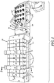
- a fluid control system 10 is modular in nature and has a plurality of valve manifold blocks 12 interconnected together. The particular number of blocks 12 is dependent on the application and the capacity of a circuit board 60 installed in each manifold block 12.
- Each manifold block 12 may have two valve stations 14 for mounting two control valves 18.
- Each control valve 18 may have an outer body 19.
- a pair of control valve bodies 19 may be mounted directly on the upper surface 13 of the manifold block 12. While a manifold block 12 is illustrated with two valve stations, it is foreseen that a manifold block with a single valve section can also be used.
- each manifold block 12 has fluid supply and fluid exhaust passages 20, 22, and 24 that extend laterally through the block to be in communication with an adjacent block 12.
- Each manifold block also has discharge passages 21 and 23 that extend to an outer wall 29 for connecting to a pneumatically operated device (not shown).
- Each manifold block also has a transverse pilot pressure passage 25.
- Each passage 20, 21, 22, 23, 24, and 25 connects to a respective port 40, 42, 44, 46, 48 and 49 at the upper surface 13 of the manifold block.
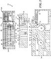
- An intermediate block 26 often referred to as a sandwich block is interposed between at least one control valve body 19 and one manifold block 12. As shown in figure 2 , the intermediate block 26 has a plurality of through holes 30, 32, 34, 36, 38 and 39 that connect the supply, discharge pilot and exhaust ports 40, 42, 44, 46, 48 and 49 of the manifold block to the supply, discharge pilot and exhaust ports 50, 52, 54, 56, 58 and 59 of the control valve 18.
- the circuit board 60 supplies electric power to the solenoid valve coil 64 of the control valve for actuating the solenoid valve and moving its spool 66.
- the spool may be biased to one direction by a spring 68 and is movable in the opposite direction by application of fluid pressure to the opposite end of the spool.
- the circuit board 60 besides having electrical power traces may also have a single communication line for serial connection to each control valve 18. Such a single line is described in more detail in U.S.S.N. 14/765,019 filed on July 31, 2015 and is incorporated herein by reference.
- the power traces and single communication line is generally attached to pin connector 74.
- the intermediate block also has power line 70 passing through for connecting pin connector 74 on circuit board 60 to the pin connector 76 in the valve body such that the solenoid coil 64 is powered by power line 70.
- Appropriate pin connectors 75 and 77 are at the top and bottom faces of the intermediate block 26 for operable connection to the respective pin connectors 74 and 76 to provide continuity of power line 70 from pin connector 74 to pin connector 76.
- a communication line 72 also extends from circuit board 60 and up through intermediate block 26 connected to a current sensor board 78 and a pressure sensor board 80 mounted in the intermediate block.
- the communication line can be incorporated in pin connectors 74 and 75.
- the current sensor board 78 is also connected to the current power line 70.
- the pressure sensor board 80 has three pressure transducers 82, 84, 86 connected to discharge through holes and supply through holes 32, 34 and 36 for sensing pressure therein.
- An optional position sensor magnet 88 may be connected to the spool and sensed by a position sensor 90 for example a Hall effect sensor also mounted on current sensor board 78.
- the parameter data such as pressure, flow, electrical current, and response time is sent via the communication line 72 to a local or remote microcontroller such as one installed in communication module 92 which houses memory storage 98 and a comparator 99.
- a second embodiment of a sandwich or intermediate block 126 is shown. It generally has two end caps 127 and 129 and a mid section 131. End cap 127 has a pin connector 133 extending out an end 135 for providing power for one or two Hall effect sensors and for a signal communication pin. Each end cap 127 and 129 is made from a non magnetic material such as plastic or aluminum and houses Hall effect sensor 190 and optional second Hall effect sensor 191 in proximity to upper walls 143 and 147. Second Hall sensor 191 is in electrical communication via a cable strap 145 that extends through mid section 131.
- the mid section 131 has the through holes 130, 132, 134, 136, 138 and 139 and similarly houses the other sensors as described for the first embodiment such as the pressure or flow, or additional sensors for sensing other parameters for example vibration or leakage sensors.
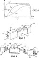
- FIG. 6 A schematic example of a normalized cycle is shown in Figure 6 .
- the normalized cycle for current being turned on and off is shown by dotted and dash curve 94 for a cycle time T 0 .
- the pressure is measured in the discharge line for a given pressure in the supply lines.
- the measured pressure values are shown as a solid curve 96 which can be stored in memory storage 98 ( Figure 1 ).
- a tolerance band or limit can then be established as shown by broken curve 97 in memory storage 98 bases on certain degradation from line 96 for which the valve is not moving quickly enough and the buildup of pressure lags.
- the comparator 99 can compare a measured parameter to the normalized profile and the respective tolerance band limit for a particular time T 1 .
- an alarm may be sent by the communication module 92 to the operator, for example via a light indicator 100 in the communication module 92 or to a light indicator 100 in the communication module 92 in a corresponding I/O unit 102 corresponding to the particular control valve indicating which control valve is below the preset tolerance limit.
- Other parameters may be substituted such as spool motion or flow rate in place of or in addition to pressure and time. The choice of parameters may be selected depending on the specific application of the control valve.
- the electronic schematic of the Hall effect sensor is disclosed in Figure 9 .
- the power connector has a ground volt pin 151, power voltage pin connector 103, and output signal connector 155.
- the Hall effect sensor 190 receives voltage from pin 103. Voltage also goes through resister R3 to transistor 157. When the Hall effect sensor 190 senses a sufficient magnetic field strength from the magnet 88 on spool, it actuates to pass voltage to line 159 through resistor R2 which turns on transistor 157 and allows voltage out through a line to indicate the position of the spool.
- indication of this degradation can be in the form of an alarm or visual notification which allows the control valve to be repaired or replaced at the next down time or scheduled maintenance before complete failure occurs which can then avoid unscheduled and unnecessary line stoppage.
- One or a plurality of intermediate blocks 26 may be added later as an accessory to the valve manifold 10 at any or all of the control valve stations.
- the information may be transmitted to the controller by wireless technology.
Description
- This invention generally relates to solenoid valve control systems in a manifold assembly. More specifically, the invention relates to a solenoid valve assembly with a detection system and a method of determining the operating condition of a solenoid operated fluid valve in such solenoid valve assembly.
- Manifold assemblies are commonly used in an assembly or industrial line to selectively direct pneumatic pressure to various pneumatically operated devices in the line. The manifold assemblies incorporate electrically actuated solenoid valves that control the direction of pneumatic flow for operating these devices. These manifold assemblies are commonly modular and are assembled from a plurality of individual manifold block members, often referred to as manifold blocks, and individual control valve bodies, often referred to as solenoid valves, valve blocks or merely valve members. The manifold assembly often has a common pilot pressure passage and main pressure passage that are connected to the solenoid valves which in turn control the flow of main pressure to a respective pneumatically operated device.
- These manifold assemblies have been known to incorporate sandwich blocks interposed between a manifold block and the solenoid actuated valve to provide shut off valves for the main pressure, to introduce a second pneumatic pressure source to a single valve station or to provide and isolate the exhaust of a single valve station from the manifold or to house pressure sensors. It is also known to install pressure sensors in sandwich blocks to monitor input and output pressures.
- These manifold assemblies have the capacity to incorporate many manifold blocks, sandwich blocks, valve stations and solenoid valves which in turn operated many devices in a large manufacturing assembly or industrial line. As each of the control valves needs to be correctly operating to maintain correct operation of the respective device, failure of a single control valve and its respective device may cause an entire assembly or industrial line to cease operating. Hence it is highly desirous and advantageous to maintain each valve in operating condition and to replace any valve before its failure during scheduled maintenance and normal down time to prevent unscheduled cessation of the line.
- This just-in-time replacement would be possible if failure of solenoid valve can be predicted. Prediction of failure is possible if failure is not sudden without warning. In other words, if anomalous behavior or early degradation of performance can be detected as an early warning indicator, then prediction of an imminent failure becomes possible.
-
U.S. Patent 6,386,229 discusses a method to anticipate failure by monitoring position of the valve in the manifold block based on certain time values. The position of a spool is detected by the use of a magnet mounted on the spool valve and a Hall effect sensor protruding into the valve body for sensing the proximity of the magnet as the spool valve moves between its two end positions. The movement is timed and if the measured time slows down beyond normal operating values, the valve is then deemed to be in need of replacement. Often these timers, pressure sensors and Hall effect sensors are built into the valve body. This approach however requires the manifold block to be initially designed and constructed with the appropriate sensors and magnets and does not address the need to reduce modifications to the valve and unmet need to monitor the many control valves and manifold members that are already installed in automated industrial and assembly lines. - Document
US 2002/0092570 A1 forming the preamble portion of claim 1 discloses a solenoid valve assembly comprising an intermediate block sandwiched between a manifold member as a base and a valve body of a solenoid valve, which comprises a pressure sensor and magnetic sensors for detecting approach of a magnet provided in a spool of the solenoid valve. - Further, document
JP 2007 327606 A - Finally, document
US 2008/0072657 A1 discloses a test bench for hydraulic manifolds as, for example, clutch actuators in automatic speed-change power submissions for motor vehicles, in which the solenoid assembly must be installed for testing. After the testing and data is collected, the data is uploaded and the solenoid assembly is accepted if the difference between the actual tested pressure and the test stand pressure points is less than the desired tolerance for all the valves during a comparison step, where a person makes this determination. There is no disclosure of an alarm if the changes are outside of a normalized cycle profile. - What is desired is a system to detect any degradation of the control valve by comparing pressure changes in the discharge lines relative to the supply lines compared to current flow that actuates the solenoid of the control valve. Further what is also desired is a sandwich block that mounts sensors that detect pressure, coil current and valve position that can be retrofitted with existing manifold blocks and control valve bodies and wherein the sensors can be used to anticipate failure of a control valve.
- The above objects are solved by the features specified in
claims 1 and 10, respectively. Advantageous and appropriate developments of the invention form the subject matter ofclaims 2 to 9. - In accordance with the present invention, a solenoid valve assembly with a detection system comprises: an intermediate block for being interposed between a manifold block and a control valve body housing a control valve with a solenoid comprising a coil for actuating the control valve, the intermediate block having a set of through holes for connecting ports in the manifold block with ports in the control valve body, a conductive circuit line for providing current to and from a power circuit line in the manifold block and to and from the coil of the solenoid of the control valve, and first and second sensors that can be used to detect failure of the control valve; wherein the first sensor is capable of detecting current supplied to the coil of the solenoid valve assembly by sensing current in the conductive circuit line, whereas the second sensor is capable of detecting another parameter in supply and discharge ports of the solenoid valve assembly by sensing said another parameter in at least one of the through holes, wherein a storage device is operably connected to the sensors to receive parameter data for comparing current with said another parameter in the supply and discharge ports to establish a normalized cycle profile during at least one cycle of the solenoid valve assembly to establish the normalized cycle profile and storing a predetermined tolerance boundary determined from the normalized cycle profile, wherein a comparator is operably connected to the storage device and the sensors for comparing parameters from the sensors to the normalized cycle profile and the predetermined tolerance boundary, and wherein an alarm device is operably connected to the comparator, which is actuated if the comparator compares a parameter from said at least one sensor with the normalized cycle profile and the predetermined tolerance boundary and finds the parameter is outside of the predetermined tolerance boundary.
- Preferably, a spool is slidably mounted in the control valve body and operated by the solenoid having said coil that operably causes the spool to move, the manifold block having a plurality of flow paths for supplying and discharging pressurized fluid to and from the ports of the solenoid valve assembly, wherein the second sensor is housed in the intermediate block for sensing pressure in at least one of said through holes, and wherein the second sensor is in the form of a sensor board mounted in the intermediate block and mounting a plurality of pressure transducers thereon for detecting pressure in a plurality of said through holes.
- Further, preferably, the first sensor is housed in the intermediate block.
- In one embodiment, the solenoid valve assembly may have a position sensor constructed for sensing a position of the spool of the solenoid valve assembly during said at least one cycle and when the comparator compares the normalized cycle profile and the predetermined tolerance boundary.
- In this embodiment, preferably, the position sensor is positioned inside the intermediate block without intruding into the control valve body for sensing the position of a magnet affixed onto the spool.
- It is further preferred that the second sensor for detecting another parameter is a pressure sensor.
- In one embodiment, a leakage sensor may be provided that detects ultrasonic vibrations caused by leaks in at least one of the flow paths.
- In another embodiment, a position sensor may be provided constructed for sensing a position of the control valve in the control valve body.
- Further, the solenoid valve assembly preferably comprises a position sensor constructed for sensing a position of the control valve in the control valve body, the intermediate block comprising a mid-section member having said set of through holes, and a pair of end-sections made from non-magnetic material and attached to the mid-section member, wherein at least one of said end-sections has an interior with said position sensor mounted under an upper wall of the end-section within the interior.
- According to another aspect of the present invention, a method of determining the operating condition of a solenoid operated fluid valve in a solenoid valve assembly as outlined above comprises the steps of: actuating the solenoid operated fluid valve for at least one cycle; measuring at least two parameters after actuating of the solenoid operated fluid valve for said at least one cycle to establish a normalized operating profile of the solenoid operated fluid valve and storing the normalized operating profile in a memory device; establishing a tolerance boundary based on the normalized operating profile and storing the tolerance boundary in the memory device; sensing and measuring said at least two parameters during normal operation of the solenoid operated fluid valve; comparing the measured two parameters with the normalized operating profile and the tolerance boundary in the memory device; and actuating an alarm if the measured parameters are outside of the tolerance boundary.
- Reference now is made to the accompanying drawings in which:
-
Figure 1 is a perspective and partially schematic overview of one embodiment according to the invention; -
Figure 2 is an exploded cross sectional view taken along 2-2 shown inFigure 1 ; -
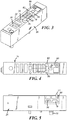
Figure 3 is an enlarged perspective view of a sandwich block shown inFigure 1 ; -
Figure 4 is a top plan view of the sandwich block shown inFigure 3 ; -
Figure 5 is an enlarged side elevational view of the sandwich block illustrating the position of the pressure board and current board installed therein; -
Figure 6 is a diagram showing an example of an established profile showing current draw to a pressure buildup for an actuation cycle of the control valve and a then established tolerance boundary of current and pressure build up during a cycle; -
Figure 7 is a perspective view of a second embodiment of a sandwich block according to the invention; -
Figure 8 is an exploded perspective view of the sandwich block shown inFigure 7 ; and -
Figure 9 is a schematic view of the electric circuit for producing a position indication signal. - Referring now to
Figures 1 and2 , afluid control system 10 is modular in nature and has a plurality ofvalve manifold blocks 12 interconnected together. The particular number ofblocks 12 is dependent on the application and the capacity of acircuit board 60 installed in eachmanifold block 12. Eachmanifold block 12 may have twovalve stations 14 for mounting twocontrol valves 18. Eachcontrol valve 18 may have anouter body 19. A pair ofcontrol valve bodies 19 may be mounted directly on theupper surface 13 of themanifold block 12. While amanifold block 12 is illustrated with two valve stations, it is foreseen that a manifold block with a single valve section can also be used. - As shown in
figure 2 , eachmanifold block 12 has fluid supply andfluid exhaust passages adjacent block 12. Each manifold block also hasdischarge passages 21 and 23 that extend to anouter wall 29 for connecting to a pneumatically operated device (not shown). Each manifold block also has a transversepilot pressure passage 25. Eachpassage respective port upper surface 13 of the manifold block. - An
intermediate block 26 often referred to as a sandwich block is interposed between at least onecontrol valve body 19 and onemanifold block 12. As shown infigure 2 , theintermediate block 26 has a plurality of throughholes exhaust ports exhaust ports control valve 18. - The
circuit board 60 supplies electric power to thesolenoid valve coil 64 of the control valve for actuating the solenoid valve and moving itsspool 66. In a well known fashion, the spool may be biased to one direction by aspring 68 and is movable in the opposite direction by application of fluid pressure to the opposite end of the spool. Although the embodiment shown is a single solenoid valve assembly, it will be understood that commercially available dual solenoid valve assemblies may also be used. - The
circuit board 60 besides having electrical power traces may also have a single communication line for serial connection to eachcontrol valve 18. Such a single line is described in more detail inU.S.S.N. 14/765,019 filed on July 31, 2015 connector 74. - Besides the through holes 30-39, the intermediate block also has power line 70 passing through for connecting
pin connector 74 oncircuit board 60 to the pin connector 76 in the valve body such that thesolenoid coil 64 is powered by power line 70.Appropriate pin connectors 75 and 77 are at the top and bottom faces of theintermediate block 26 for operable connection to therespective pin connectors 74 and 76 to provide continuity of power line 70 frompin connector 74 to pin connector 76. - A
communication line 72 also extends fromcircuit board 60 and up throughintermediate block 26 connected to acurrent sensor board 78 and apressure sensor board 80 mounted in the intermediate block. The communication line can be incorporated inpin connectors current sensor board 78 is also connected to the current power line 70. Thepressure sensor board 80 has threepressure transducers holes - An optional
position sensor magnet 88 may be connected to the spool and sensed by aposition sensor 90 for example a Hall effect sensor also mounted oncurrent sensor board 78. - The parameter data such as pressure, flow, electrical current, and response time is sent via the
communication line 72 to a local or remote microcontroller such as one installed incommunication module 92 which housesmemory storage 98 and acomparator 99. - Referring now to
Figures 7 and 8 , a second embodiment of a sandwich orintermediate block 126 is shown. It generally has twoend caps mid section 131.End cap 127 has apin connector 133 extending out anend 135 for providing power for one or two Hall effect sensors and for a signal communication pin. Eachend cap Hall effect sensor 190 and optional secondHall effect sensor 191 in proximity toupper walls Second Hall sensor 191 is in electrical communication via acable strap 145 that extends throughmid section 131. - The
mid section 131 has the throughholes - A schematic example of a normalized cycle is shown in
Figure 6 . The normalized cycle for current being turned on and off is shown by dotted anddash curve 94 for a cycle time T0. The pressure is measured in the discharge line for a given pressure in the supply lines. The measured pressure values are shown as asolid curve 96 which can be stored in memory storage 98 (Figure 1 ). A tolerance band or limit can then be established as shown bybroken curve 97 inmemory storage 98 bases on certain degradation fromline 96 for which the valve is not moving quickly enough and the buildup of pressure lags. Thecomparator 99 can compare a measured parameter to the normalized profile and the respective tolerance band limit for a particular time T1. Once the degradation goes below i.e outside the tolerance limit, an alarm may be sent by thecommunication module 92 to the operator, for example via alight indicator 100 in thecommunication module 92 or to alight indicator 100 in thecommunication module 92 in a corresponding I/O unit 102 corresponding to the particular control valve indicating which control valve is below the preset tolerance limit. Other parameters may be substituted such as spool motion or flow rate in place of or in addition to pressure and time. The choice of parameters may be selected depending on the specific application of the control valve. - The electronic schematic of the Hall effect sensor is disclosed in
Figure 9 . The power connector has aground volt pin 151, powervoltage pin connector 103, andoutput signal connector 155. TheHall effect sensor 190 receives voltage frompin 103. Voltage also goes through resister R3 totransistor 157. When theHall effect sensor 190 senses a sufficient magnetic field strength from themagnet 88 on spool, it actuates to pass voltage to line 159 through resistor R2 which turns ontransistor 157 and allows voltage out through a line to indicate the position of the spool. - At the time when a control valve shows some degradation before a complete failure, indication of this degradation can be in the form of an alarm or visual notification which allows the control valve to be repaired or replaced at the next down time or scheduled maintenance before complete failure occurs which can then avoid unscheduled and unnecessary line stoppage.
- By having the pressure sensors, current sensors, and other parameter sensors being installed in the intermediate block, one can retrofit a standard existing
control valve 18 with theintermediate block 26 interposed between themanifold block 12 and the control valve body with no further modification to thecontrol valve body 19 ormanifold block 12. One or a plurality ofintermediate blocks 26 may be added later as an accessory to thevalve manifold 10 at any or all of the control valve stations. - It is also foreseen that the information may be transmitted to the controller by wireless technology.
- Other variations and modifications are possible without departing from the scope of the present invention as defined by the appended claims.
Claims (10)
- A solenoid valve assembly with a manifold block (12), a control valve body (19) and a detection system, the solenoid valve assembly further comprising:an intermediate block (26) being interposed between the manifold block (12) and the control valve body (19) housing a control valve (18) with a solenoid comprising a coil (64) for actuating said control valve (18);said intermediate block (26) having a set of through holes (30, 32, 34, 36, 38, 39) for connecting ports (40, 42, 44, 46, 48, 49) in said manifold block (12) with ports (50, 52, 54, 56, 58, 59) in said control valve body (19);a conductive circuit line (70) for providing current to and from a power circuit line in said manifold block (12) and to and from said coil (64) of said solenoid of said control valve (18); andfirst and second sensors (78, 80) that can be used to detect failure of said control valve (18);characterized in that said first sensor (78) is capable of detecting current supplied to said coil (64) of said solenoid valve assembly by sensing current in said conductive circuit line (70), whereas said second sensor (80) is capable of detecting another parameter in supply and discharge ports (52, 54, 56) of said solenoid valve assembly by sensing said another parameter in at least one of said through holes (30, 32, 34, 36, 38, 39);wherein a storage device (98) is operably connected to said sensors (78, 80) to receive parameter data for comparing current with said another parameter in said supply and discharge ports (52, 54, 56) to establish a normalized cycle profile during at least one cycle of said solenoid valve assembly to establish said normalized cycle profile and storing a predetermined tolerance boundary determined from said normalized cycle profile;wherein a comparator (99) is operably connected to the storage device (98) and said sensors (78, 80) for comparing parameters from said sensors (78, 80) to said normalized cycle profile and said predetermined tolerance boundary; andwherein an alarm device (100) is operably connected to said comparator (99), which is actuated if said comparator (99) compares a parameter from said sensors (78, 80) with the normalized cycle profile and the predetermined tolerance boundary and finds the parameter is outside of said predetermined tolerance boundary.
- A solenoid valve assembly according to claim 1, characterized in that:a spool (66) is slidably mounted in said control valve body (19) and operated by said solenoid having said coil (64) that operably causes the spool (66) to move;said manifold block (12) having a plurality of flow paths (20, 21, 22, 23, 24) for supplying and discharging pressurized fluid to and from said ports of the solenoid valve assembly;wherein said second sensor (80) is housed in said intermediate block (26; 126) for sensing pressure in at least one of said through holes (30, 32, 34, 36, 38, 39); andwherein said second sensor (80) is in the form of a sensor board mounted in said intermediate block (26; 126) and mounting a plurality of pressure transducers (82, 84, 86) thereon for detecting pressure in a plurality of said through holes (30, 32, 34, 36, 38, 39).
- A solenoid valve assembly according to claim 1 or 2, characterized in that said first sensor (78) is housed in said intermediate block (26).
- A solenoid valve assembly according to claim 2 or 3, characterized by a position sensor (90) constructed for sensing a position of said spool (66) of said solenoid valve assembly during said at least one cycle and when said comparator (99) compares said normalized cycle profile and said predetermined tolerance boundary.
- A solenoid valve assembly according to claim 4, characterized in that said position sensor (90) is positioned inside the intermediate block (26) without intruding into said control valve body (19) for sensing the position of a magnet (88) affixed onto said spool (66).
- A solenoid valve assembly according to claim 1, characterized in that said second sensor for detecting another parameter is a pressure sensor (80).
- A solenoid valve assembly according to any one of claims 1 to 6, characterized by a leakage sensor that detects ultrasonic vibrations caused by leaks in at least one of the flow paths.
- A solenoid valve assembly according to claim 1, characterized by a position sensor (90) constructed for sensing a position of said control valve (18) in said control valve body (19).
- A solenoid valve assembly according to claim 2, characterized by:a position sensor (190, 191) constructed for sensing a position of said control valve (18) in said control valve body (19) ;said intermediate block (126) having a mid-section member (131) having said set of through holes (130, 132, 134, 136, 138, 139); anda pair of end-sections (127, 129) made from non-magnetic material and attached to said mid-section member (131);wherein at least one of said end-sections (127, 129) has an interior with said position sensor (190, 191) mounted under an upper wall (143, 147) of said end-section (127, 129) within said interior.
- A method of determining the operating condition of a solenoid operated fluid valve (18) in a solenoid valve assembly according to any one of the preceding claims, characterized by:actuating said solenoid operated fluid valve (18) for at least one cycle;measuring at least two parameters after actuating of said solenoid operated fluid valve (18) for said at least one cycle to establish a normalized operating profile of said solenoid operated fluid valve (18) and storing said normalized operating profile in a memory device (98);establishing a tolerance boundary based on said normalized operating profile and storing said tolerance boundary in said memory device (98);sensing and measuring said at least two parameters during normal operation of said solenoid operated fluid valve (18);comparing said measured two parameters with said normalized operating profile and said tolerance boundary in said memory device (98); andactuating an alarm if said measured parameters are outside of said tolerance boundary.
Applications Claiming Priority (1)
| Application Number | Priority Date | Filing Date | Title |
|---|---|---|---|
| PCT/US2017/021088 WO2018164669A1 (en) | 2017-03-07 | 2017-03-07 | A device and method for anticipating failure in a solenoid valve for a manifold assembly |
Publications (3)
| Publication Number | Publication Date |
|---|---|
| EP3592989A1 EP3592989A1 (en) | 2020-01-15 |
| EP3592989A4 EP3592989A4 (en) | 2020-11-04 |
| EP3592989B1 true EP3592989B1 (en) | 2022-01-12 |
Family
ID=63447937
Family Applications (1)
| Application Number | Title | Priority Date | Filing Date |
|---|---|---|---|
| EP17899476.0A Active EP3592989B1 (en) | 2017-03-07 | 2017-03-07 | A device and method for anticipating failure in a solenoid valve for a manifold assembly |
Country Status (7)
| Country | Link |
|---|---|
| US (1) | US11761462B2 (en) |
| EP (1) | EP3592989B1 (en) |
| CN (1) | CN110603385B (en) |
| BR (1) | BR112019018713B1 (en) |
| CA (2) | CA3206116A1 (en) |
| MX (1) | MX2019010737A (en) |
| WO (1) | WO2018164669A1 (en) |
Families Citing this family (11)
| Publication number | Priority date | Publication date | Assignee | Title |
|---|---|---|---|---|
| US10613553B2 (en) * | 2013-07-09 | 2020-04-07 | Deka Products Limited Partnership | Modular valve apparatus and system |
| EP3786502B1 (en) * | 2018-04-27 | 2023-08-09 | SMC Corporation | Electromagnetic valve system |
| EP4045402B1 (en) * | 2019-10-15 | 2024-04-17 | Airbus Operations Limited | A method of removing hydraulic fluid from an aircraft hydraulic system, an aircraft hydraulic system, and an aircraft |
| JP7189114B2 (en) * | 2019-12-04 | 2022-12-13 | Ckd株式会社 | solenoid valve manifold |
| DE102019135575A1 (en) * | 2019-12-20 | 2021-06-24 | Bürkert Werke GmbH & Co. KG | Valve terminal with diagnostic module |
| GB2596863A (en) * | 2020-07-10 | 2022-01-12 | Norgen Ltd | Diagnostic valve island |
| NO346531B1 (en) * | 2021-05-18 | 2022-09-26 | Ideation As | Detection of safe activation of shutdown valves and blowdown valves |
| CN113309752B (en) * | 2021-06-03 | 2022-06-14 | 深圳市浦联智能科技有限公司 | Proportional valve hydraulic control system |
| US20230116100A1 (en) * | 2021-10-12 | 2023-04-13 | Parker-Hannifin Corporation | Valve bank and smart control valve |
| EP4212741A1 (en) * | 2022-01-18 | 2023-07-19 | Asco Numatics GmbH | Device and method for controlling and regulating fluid streams |
| JP2024051642A (en) * | 2022-09-30 | 2024-04-11 | Smc株式会社 | Manifold type air pressure supply device and manifold block used therein |
Family Cites Families (53)
| Publication number | Priority date | Publication date | Assignee | Title |
|---|---|---|---|---|
| US4542649A (en) | 1983-07-19 | 1985-09-24 | Charbonneau And Godfrey Associates | Motor operated valve analysis and testing system |
| US5524484A (en) | 1993-12-22 | 1996-06-11 | Westinghouse Electric Corporation | Solenoid operated valve diagnostic system |
| FR2760061B1 (en) | 1997-02-21 | 1999-04-30 | Ksb Sa | ACTUATOR TAP WHICH CAN BE MONITORED FOR OPERATION |
| US6164323A (en) * | 1999-07-12 | 2000-12-26 | Numatics, Incorporated | Solenoid valve control system |
| JP3530775B2 (en) | 1999-07-16 | 2004-05-24 | Smc株式会社 | Solenoid valve operation management device |
| JP4329205B2 (en) * | 1999-09-10 | 2009-09-09 | トヨタ自動車株式会社 | Pressure device abnormality detection device for hydraulic brake system |
| JP3590762B2 (en) | 2000-09-05 | 2004-11-17 | Smc株式会社 | Manifold valve with position detection function |
| JP3609331B2 (en) | 2000-09-12 | 2005-01-12 | Smc株式会社 | Manifold valve with position detection function |
| GB2373873B (en) | 2000-09-18 | 2002-12-04 | Smc Kk | Method of driving and controlling a solenoid-operated valve |
| JP2002174358A (en) | 2000-12-08 | 2002-06-21 | Smc Corp | Solenoid valve with failure diagnostic function |
| JP3637282B2 (en) * | 2001-01-15 | 2005-04-13 | Smc株式会社 | Solenoid valve with magnetic sensor |
| JP3590772B2 (en) * | 2001-01-16 | 2004-11-17 | Smc株式会社 | Solenoid valve with sensor |
| US6917203B1 (en) | 2001-09-07 | 2005-07-12 | The United States Of America As Represented By The Administrator Of The National Aeronautics And Space Administration | Current signature sensor |
| JP3523629B2 (en) | 2001-10-18 | 2004-04-26 | Smc株式会社 | Valve unit that can monitor output pressure |
| JP3968647B2 (en) * | 2002-06-11 | 2007-08-29 | Smc株式会社 | Manifold valve with position detection mechanism |
| JP4003219B2 (en) | 2002-06-25 | 2007-11-07 | Smc株式会社 | Manifold valve with position detection mechanism |
| JP4072756B2 (en) | 2002-07-05 | 2008-04-09 | Smc株式会社 | Manifold valve with sensor |
| DE10242969B3 (en) | 2002-09-17 | 2004-04-29 | Festo Ag & Co. | Pneumatic arrangement with several maintenance modules for compressed air preparation |
| US20040118466A1 (en) * | 2002-12-19 | 2004-06-24 | Eaton Corporation | Electro-hydraulic manifold assembly and pressure sensor therefor |
| WO2004081436A1 (en) | 2003-03-10 | 2004-09-23 | Shikoku Research Institute Incorporated | Motorized valve diagnosing method and device |
| DE10311475B4 (en) | 2003-03-15 | 2006-04-13 | Festo Ag & Co. | Module for a valve battery |
| US7798174B2 (en) * | 2003-08-20 | 2010-09-21 | Eaton Corporation | Electric fluid servo valve and method of making same |
| DE10344480B3 (en) | 2003-09-24 | 2005-06-16 | Sauer-Danfoss Aps | Hydraulic valve arrangement |
| WO2005062961A2 (en) | 2003-12-23 | 2005-07-14 | Rain Bird Corporation | Modular and expandable irrigation controller |
| US20070034264A1 (en) * | 2005-08-12 | 2007-02-15 | Stonel Corporation | Apparatus for valve communication and control |
| JP4795855B2 (en) * | 2006-06-09 | 2011-10-19 | 日本原子力発電株式会社 | Inspection method and apparatus for electromagnetic valve in plant |
| US7707872B2 (en) * | 2006-09-25 | 2010-05-04 | Eaton Corporation | Method for testing a hydraulic manifold |
| US7432721B2 (en) | 2006-12-18 | 2008-10-07 | Temic Automotive Of North America, Inc. | Solenoid actuator motion detection |
| US7539560B2 (en) | 2007-01-05 | 2009-05-26 | Dresser, Inc. | Control valve and positioner diagnostics |
| WO2008119306A1 (en) | 2007-03-29 | 2008-10-09 | Festo Ag & Co. Kg | Controller module for a valve array |
| JP4359855B2 (en) | 2007-07-09 | 2009-11-11 | Smc株式会社 | Solenoid valve drive circuit and solenoid valve |
| US7753740B2 (en) | 2007-07-20 | 2010-07-13 | Numatics, Incorporated | Modular electrical bus system |
| US8265794B2 (en) | 2007-10-01 | 2012-09-11 | Westlock Controls Corporation | Knowledge based valve control method |
| US20090088874A1 (en) | 2007-10-02 | 2009-04-02 | Emmanuel Arceo | Valve manifold assemblies and method of operating valve manifold assemblies |
| GB2453947A (en) | 2007-10-23 | 2009-04-29 | Vetco Gray Controls Ltd | Solenoid coil current used in armature movement monitoring |
| US8271141B2 (en) * | 2008-06-09 | 2012-09-18 | Ross Operating Valve Company | Control valve system with cycle monitoring, diagnostics and degradation prediction |
| JP5460982B2 (en) | 2008-07-30 | 2014-04-02 | 東京エレクトロン株式会社 | Valve body, particle intrusion prevention mechanism, exhaust control device, and substrate processing apparatus |
| US8020585B2 (en) * | 2008-08-22 | 2011-09-20 | Airgas, Inc. | Apparatus and method for detecting a leak within a duplex valve assembly |
| JP5093090B2 (en) * | 2008-12-25 | 2012-12-05 | アイシン・エィ・ダブリュ株式会社 | Solenoid valve device and power transmission device |
| GB0901947D0 (en) | 2009-02-09 | 2009-03-11 | Rolls Royce Plc | Determining solenoid health |
| DE102009017861A1 (en) | 2009-04-17 | 2010-10-21 | Festo Ag & Co. Kg | valve means |
| CN201636110U (en) * | 2009-12-09 | 2010-11-17 | 中冶南方工程技术有限公司 | Special three-way electro-hydraulic servo valve for rolling mill pressing system |
| US8844561B2 (en) * | 2010-05-20 | 2014-09-30 | Eaton Corporation | Isolation valve with integrated sensor |
| US9695579B2 (en) | 2011-03-15 | 2017-07-04 | Sloan Valve Company | Automatic faucets |
| US20140069207A1 (en) * | 2011-03-18 | 2014-03-13 | Soneter, LLC | Methods and apparatus for fluid flow measurement |
| US8812914B2 (en) | 2011-10-24 | 2014-08-19 | Fisher Controls International, Llc | Field control devices having pre-defined error-states and related methods |
| DE102012005224A1 (en) | 2012-03-15 | 2013-09-19 | Festo Ag & Co. Kg | Fluid system and method of operating a fluid system |
| US9128008B2 (en) | 2012-04-20 | 2015-09-08 | Kent Tabor | Actuator predictive system |
| JP5717073B2 (en) | 2012-05-09 | 2015-05-13 | Smc株式会社 | Solenoid valve system |
| US9022069B2 (en) | 2013-03-15 | 2015-05-05 | Mac Valves, Inc. | Solenoid operated valve with constant bleed port |
| JP5574201B1 (en) | 2013-04-08 | 2014-08-20 | Smc株式会社 | Spool valve |
| JP6449288B2 (en) | 2013-11-22 | 2019-01-09 | フェスト アーゲー ウント コー カーゲー | Valve assembly and fluid system |
| US10180191B2 (en) * | 2014-06-20 | 2019-01-15 | Asco, L.P. | Zoned manifold assembly for solenoid valve control system |
-
2017
- 2017-03-07 EP EP17899476.0A patent/EP3592989B1/en active Active
- 2017-03-07 US US16/492,512 patent/US11761462B2/en active Active
- 2017-03-07 CA CA3206116A patent/CA3206116A1/en active Pending
- 2017-03-07 CN CN201780090447.4A patent/CN110603385B/en active Active
- 2017-03-07 WO PCT/US2017/021088 patent/WO2018164669A1/en unknown
- 2017-03-07 MX MX2019010737A patent/MX2019010737A/en unknown
- 2017-03-07 BR BR112019018713-8A patent/BR112019018713B1/en active IP Right Grant
- 2017-03-07 CA CA3057060A patent/CA3057060C/en active Active
Also Published As
| Publication number | Publication date |
|---|---|
| BR112019018713A2 (en) | 2020-04-07 |
| CN110603385B (en) | 2022-11-22 |
| US11761462B2 (en) | 2023-09-19 |
| BR112019018713B1 (en) | 2024-02-06 |
| CN110603385A (en) | 2019-12-20 |
| CA3057060C (en) | 2023-08-29 |
| US20210131459A1 (en) | 2021-05-06 |
| MX2019010737A (en) | 2020-01-20 |
| EP3592989A1 (en) | 2020-01-15 |
| CA3057060A1 (en) | 2018-09-13 |
| EP3592989A4 (en) | 2020-11-04 |
| CA3206116A1 (en) | 2018-09-13 |
| WO2018164669A1 (en) | 2018-09-13 |
Similar Documents
| Publication | Publication Date | Title |
|---|---|---|
| EP3592989B1 (en) | A device and method for anticipating failure in a solenoid valve for a manifold assembly | |
| US11408450B2 (en) | Device and method for monitoring response time in a valve manifold assembly | |
| US9891135B2 (en) | Fault detection system for actuator | |
| EP1070893B1 (en) | Method and device for managing operation of solenoid valve | |
| US8271141B2 (en) | Control valve system with cycle monitoring, diagnostics and degradation prediction | |
| JP6158914B2 (en) | Actuator prediction system | |
| CN112344080B (en) | System comprising a switching valve, a pneumatic actuator, a solenoid valve and a function monitoring device | |
| CN110360375B (en) | Valve maintenance status detection | |
| US11085553B2 (en) | Valve electronics and valve arrangement | |
| CA3167323A1 (en) | A device and method for anticipating failure in a solenoid pilot operated control valve for a fieldbus manifold assembly | |
| CN110857710B (en) | Measurement of operating parameters of an actuator | |
| JP2020060202A (en) | solenoid valve | |
| CN108437967A (en) | A kind of vacuum pump of electric automobile method for testing performance based on off-line test equipment | |
| US20230116100A1 (en) | Valve bank and smart control valve | |
| JP2000046016A (en) | Maintenance inspection system for hydraulic device | |
| CN111749955A (en) | System and method | |
| KR20230097385A (en) | Hydraulic monitoring system used in hydraulic equipment | |
| KR20110137586A (en) | Electro-pneumatic unification control panel |
Legal Events
| Date | Code | Title | Description |
|---|---|---|---|
| STAA | Information on the status of an ep patent application or granted ep patent |
Free format text: STATUS: THE INTERNATIONAL PUBLICATION HAS BEEN MADE |
|
| PUAI | Public reference made under article 153(3) epc to a published international application that has entered the european phase |
Free format text: ORIGINAL CODE: 0009012 |
|
| STAA | Information on the status of an ep patent application or granted ep patent |
Free format text: STATUS: REQUEST FOR EXAMINATION WAS MADE |
|
| 17P | Request for examination filed |
Effective date: 20190926 |
|
| AK | Designated contracting states |
Kind code of ref document: A1 Designated state(s): AL AT BE BG CH CY CZ DE DK EE ES FI FR GB GR HR HU IE IS IT LI LT LU LV MC MK MT NL NO PL PT RO RS SE SI SK SM TR |
|
| AX | Request for extension of the european patent |
Extension state: BA ME |
|
| DAV | Request for validation of the european patent (deleted) | ||
| DAX | Request for extension of the european patent (deleted) | ||
| A4 | Supplementary search report drawn up and despatched |
Effective date: 20201002 |
|
| RIC1 | Information provided on ipc code assigned before grant |
Ipc: F16K 31/06 20060101ALI20200928BHEP Ipc: F16K 31/02 20060101ALI20200928BHEP Ipc: F15B 13/043 20060101AFI20200928BHEP Ipc: F15B 13/08 20060101ALI20200928BHEP Ipc: F16K 37/00 20060101ALI20200928BHEP Ipc: F16K 27/00 20060101ALI20200928BHEP |
|
| GRAP | Despatch of communication of intention to grant a patent |
Free format text: ORIGINAL CODE: EPIDOSNIGR1 |
|
| STAA | Information on the status of an ep patent application or granted ep patent |
Free format text: STATUS: GRANT OF PATENT IS INTENDED |
|
| INTG | Intention to grant announced |
Effective date: 20210805 |
|
| GRAS | Grant fee paid |
Free format text: ORIGINAL CODE: EPIDOSNIGR3 |
|
| GRAA | (expected) grant |
Free format text: ORIGINAL CODE: 0009210 |
|
| STAA | Information on the status of an ep patent application or granted ep patent |
Free format text: STATUS: THE PATENT HAS BEEN GRANTED |
|
| AK | Designated contracting states |
Kind code of ref document: B1 Designated state(s): AL AT BE BG CH CY CZ DE DK EE ES FI FR GB GR HR HU IE IS IT LI LT LU LV MC MK MT NL NO PL PT RO RS SE SI SK SM TR |
|
| REG | Reference to a national code |
Ref country code: GB Ref legal event code: FG4D |
|
| REG | Reference to a national code |
Ref country code: CH Ref legal event code: EP |
|
| REG | Reference to a national code |
Ref country code: DE Ref legal event code: R096 Ref document number: 602017052392 Country of ref document: DE |
|
| REG | Reference to a national code |
Ref country code: IE Ref legal event code: FG4D |
|
| REG | Reference to a national code |
Ref country code: AT Ref legal event code: REF Ref document number: 1462571 Country of ref document: AT Kind code of ref document: T Effective date: 20220215 |
|
| REG | Reference to a national code |
Ref country code: LT Ref legal event code: MG9D |
|
| REG | Reference to a national code |
Ref country code: NL Ref legal event code: MP Effective date: 20220112 |
|
| REG | Reference to a national code |
Ref country code: AT Ref legal event code: MK05 Ref document number: 1462571 Country of ref document: AT Kind code of ref document: T Effective date: 20220112 |
|
| PG25 | Lapsed in a contracting state [announced via postgrant information from national office to epo] |
Ref country code: NL Free format text: LAPSE BECAUSE OF FAILURE TO SUBMIT A TRANSLATION OF THE DESCRIPTION OR TO PAY THE FEE WITHIN THE PRESCRIBED TIME-LIMIT Effective date: 20220112 |
|
| PG25 | Lapsed in a contracting state [announced via postgrant information from national office to epo] |
Ref country code: SE Free format text: LAPSE BECAUSE OF FAILURE TO SUBMIT A TRANSLATION OF THE DESCRIPTION OR TO PAY THE FEE WITHIN THE PRESCRIBED TIME-LIMIT Effective date: 20220112 Ref country code: RS Free format text: LAPSE BECAUSE OF FAILURE TO SUBMIT A TRANSLATION OF THE DESCRIPTION OR TO PAY THE FEE WITHIN THE PRESCRIBED TIME-LIMIT Effective date: 20220112 Ref country code: PT Free format text: LAPSE BECAUSE OF FAILURE TO SUBMIT A TRANSLATION OF THE DESCRIPTION OR TO PAY THE FEE WITHIN THE PRESCRIBED TIME-LIMIT Effective date: 20220512 Ref country code: NO Free format text: LAPSE BECAUSE OF FAILURE TO SUBMIT A TRANSLATION OF THE DESCRIPTION OR TO PAY THE FEE WITHIN THE PRESCRIBED TIME-LIMIT Effective date: 20220412 Ref country code: LT Free format text: LAPSE BECAUSE OF FAILURE TO SUBMIT A TRANSLATION OF THE DESCRIPTION OR TO PAY THE FEE WITHIN THE PRESCRIBED TIME-LIMIT Effective date: 20220112 Ref country code: HR Free format text: LAPSE BECAUSE OF FAILURE TO SUBMIT A TRANSLATION OF THE DESCRIPTION OR TO PAY THE FEE WITHIN THE PRESCRIBED TIME-LIMIT Effective date: 20220112 Ref country code: ES Free format text: LAPSE BECAUSE OF FAILURE TO SUBMIT A TRANSLATION OF THE DESCRIPTION OR TO PAY THE FEE WITHIN THE PRESCRIBED TIME-LIMIT Effective date: 20220112 Ref country code: BG Free format text: LAPSE BECAUSE OF FAILURE TO SUBMIT A TRANSLATION OF THE DESCRIPTION OR TO PAY THE FEE WITHIN THE PRESCRIBED TIME-LIMIT Effective date: 20220412 |
|
| PG25 | Lapsed in a contracting state [announced via postgrant information from national office to epo] |
Ref country code: PL Free format text: LAPSE BECAUSE OF FAILURE TO SUBMIT A TRANSLATION OF THE DESCRIPTION OR TO PAY THE FEE WITHIN THE PRESCRIBED TIME-LIMIT Effective date: 20220112 Ref country code: LV Free format text: LAPSE BECAUSE OF FAILURE TO SUBMIT A TRANSLATION OF THE DESCRIPTION OR TO PAY THE FEE WITHIN THE PRESCRIBED TIME-LIMIT Effective date: 20220112 Ref country code: GR Free format text: LAPSE BECAUSE OF FAILURE TO SUBMIT A TRANSLATION OF THE DESCRIPTION OR TO PAY THE FEE WITHIN THE PRESCRIBED TIME-LIMIT Effective date: 20220413 Ref country code: FI Free format text: LAPSE BECAUSE OF FAILURE TO SUBMIT A TRANSLATION OF THE DESCRIPTION OR TO PAY THE FEE WITHIN THE PRESCRIBED TIME-LIMIT Effective date: 20220112 Ref country code: AT Free format text: LAPSE BECAUSE OF FAILURE TO SUBMIT A TRANSLATION OF THE DESCRIPTION OR TO PAY THE FEE WITHIN THE PRESCRIBED TIME-LIMIT Effective date: 20220112 |
|
| PG25 | Lapsed in a contracting state [announced via postgrant information from national office to epo] |
Ref country code: IS Free format text: LAPSE BECAUSE OF FAILURE TO SUBMIT A TRANSLATION OF THE DESCRIPTION OR TO PAY THE FEE WITHIN THE PRESCRIBED TIME-LIMIT Effective date: 20220512 |
|
| REG | Reference to a national code |
Ref country code: DE Ref legal event code: R097 Ref document number: 602017052392 Country of ref document: DE |
|
| PG25 | Lapsed in a contracting state [announced via postgrant information from national office to epo] |
Ref country code: SM Free format text: LAPSE BECAUSE OF FAILURE TO SUBMIT A TRANSLATION OF THE DESCRIPTION OR TO PAY THE FEE WITHIN THE PRESCRIBED TIME-LIMIT Effective date: 20220112 Ref country code: SK Free format text: LAPSE BECAUSE OF FAILURE TO SUBMIT A TRANSLATION OF THE DESCRIPTION OR TO PAY THE FEE WITHIN THE PRESCRIBED TIME-LIMIT Effective date: 20220112 Ref country code: RO Free format text: LAPSE BECAUSE OF FAILURE TO SUBMIT A TRANSLATION OF THE DESCRIPTION OR TO PAY THE FEE WITHIN THE PRESCRIBED TIME-LIMIT Effective date: 20220112 Ref country code: MC Free format text: LAPSE BECAUSE OF FAILURE TO SUBMIT A TRANSLATION OF THE DESCRIPTION OR TO PAY THE FEE WITHIN THE PRESCRIBED TIME-LIMIT Effective date: 20220112 Ref country code: EE Free format text: LAPSE BECAUSE OF FAILURE TO SUBMIT A TRANSLATION OF THE DESCRIPTION OR TO PAY THE FEE WITHIN THE PRESCRIBED TIME-LIMIT Effective date: 20220112 Ref country code: DK Free format text: LAPSE BECAUSE OF FAILURE TO SUBMIT A TRANSLATION OF THE DESCRIPTION OR TO PAY THE FEE WITHIN THE PRESCRIBED TIME-LIMIT Effective date: 20220112 Ref country code: CZ Free format text: LAPSE BECAUSE OF FAILURE TO SUBMIT A TRANSLATION OF THE DESCRIPTION OR TO PAY THE FEE WITHIN THE PRESCRIBED TIME-LIMIT Effective date: 20220112 |
|
| REG | Reference to a national code |
Ref country code: CH Ref legal event code: PL |
|
| PLBE | No opposition filed within time limit |
Free format text: ORIGINAL CODE: 0009261 |
|
| STAA | Information on the status of an ep patent application or granted ep patent |
Free format text: STATUS: NO OPPOSITION FILED WITHIN TIME LIMIT |
|
| PG25 | Lapsed in a contracting state [announced via postgrant information from national office to epo] |
Ref country code: AL Free format text: LAPSE BECAUSE OF FAILURE TO SUBMIT A TRANSLATION OF THE DESCRIPTION OR TO PAY THE FEE WITHIN THE PRESCRIBED TIME-LIMIT Effective date: 20220112 |
|
| REG | Reference to a national code |
Ref country code: BE Ref legal event code: MM Effective date: 20220331 |
|
| 26N | No opposition filed |
Effective date: 20221013 |
|
| PG25 | Lapsed in a contracting state [announced via postgrant information from national office to epo] |
Ref country code: LI Free format text: LAPSE BECAUSE OF NON-PAYMENT OF DUE FEES Effective date: 20220331 Ref country code: IE Free format text: LAPSE BECAUSE OF NON-PAYMENT OF DUE FEES Effective date: 20220307 Ref country code: CH Free format text: LAPSE BECAUSE OF NON-PAYMENT OF DUE FEES Effective date: 20220331 |
|
| PG25 | Lapsed in a contracting state [announced via postgrant information from national office to epo] |
Ref country code: SI Free format text: LAPSE BECAUSE OF FAILURE TO SUBMIT A TRANSLATION OF THE DESCRIPTION OR TO PAY THE FEE WITHIN THE PRESCRIBED TIME-LIMIT Effective date: 20220112 Ref country code: BE Free format text: LAPSE BECAUSE OF NON-PAYMENT OF DUE FEES Effective date: 20220331 |
|
| PGFP | Annual fee paid to national office [announced via postgrant information from national office to epo] |
Ref country code: LU Payment date: 20230221 Year of fee payment: 7 Ref country code: FR Payment date: 20230222 Year of fee payment: 7 |
|
| PGFP | Annual fee paid to national office [announced via postgrant information from national office to epo] |
Ref country code: GB Payment date: 20230221 Year of fee payment: 7 Ref country code: DE Payment date: 20230221 Year of fee payment: 7 |
|
| PG25 | Lapsed in a contracting state [announced via postgrant information from national office to epo] |
Ref country code: IT Free format text: LAPSE BECAUSE OF FAILURE TO SUBMIT A TRANSLATION OF THE DESCRIPTION OR TO PAY THE FEE WITHIN THE PRESCRIBED TIME-LIMIT Effective date: 20220112 |
|
| P01 | Opt-out of the competence of the unified patent court (upc) registered |
Effective date: 20230825 |
|
| PGFP | Annual fee paid to national office [announced via postgrant information from national office to epo] |
Ref country code: LU Payment date: 20240220 Year of fee payment: 8 |