EP3592570B1 - Sicherheitsdokument mit einem 3d-farbfoto - Google Patents
Sicherheitsdokument mit einem 3d-farbfoto Download PDFInfo
- Publication number
- EP3592570B1 EP3592570B1 EP18718009.6A EP18718009A EP3592570B1 EP 3592570 B1 EP3592570 B1 EP 3592570B1 EP 18718009 A EP18718009 A EP 18718009A EP 3592570 B1 EP3592570 B1 EP 3592570B1
- Authority
- EP
- European Patent Office
- Prior art keywords
- image
- laser
- colour
- portrait
- pattern
- Prior art date
- Legal status (The legal status is an assumption and is not a legal conclusion. Google has not performed a legal analysis and makes no representation as to the accuracy of the status listed.)
- Active
Links
Images


Classifications
-
- B—PERFORMING OPERATIONS; TRANSPORTING
- B42—BOOKBINDING; ALBUMS; FILES; SPECIAL PRINTED MATTER
- B42D—BOOKS; BOOK COVERS; LOOSE LEAVES; PRINTED MATTER CHARACTERISED BY IDENTIFICATION OR SECURITY FEATURES; PRINTED MATTER OF SPECIAL FORMAT OR STYLE NOT OTHERWISE PROVIDED FOR; DEVICES FOR USE THEREWITH AND NOT OTHERWISE PROVIDED FOR; MOVABLE-STRIP WRITING OR READING APPARATUS
- B42D25/00—Information-bearing cards or sheet-like structures characterised by identification or security features; Manufacture thereof
- B42D25/40—Manufacture
- B42D25/405—Marking
- B42D25/41—Marking using electromagnetic radiation
-
- B—PERFORMING OPERATIONS; TRANSPORTING
- B42—BOOKBINDING; ALBUMS; FILES; SPECIAL PRINTED MATTER
- B42D—BOOKS; BOOK COVERS; LOOSE LEAVES; PRINTED MATTER CHARACTERISED BY IDENTIFICATION OR SECURITY FEATURES; PRINTED MATTER OF SPECIAL FORMAT OR STYLE NOT OTHERWISE PROVIDED FOR; DEVICES FOR USE THEREWITH AND NOT OTHERWISE PROVIDED FOR; MOVABLE-STRIP WRITING OR READING APPARATUS
- B42D25/00—Information-bearing cards or sheet-like structures characterised by identification or security features; Manufacture thereof
- B42D25/20—Information-bearing cards or sheet-like structures characterised by identification or security features; Manufacture thereof characterised by a particular use or purpose
- B42D25/23—Identity cards
-
- B—PERFORMING OPERATIONS; TRANSPORTING
- B42—BOOKBINDING; ALBUMS; FILES; SPECIAL PRINTED MATTER
- B42D—BOOKS; BOOK COVERS; LOOSE LEAVES; PRINTED MATTER CHARACTERISED BY IDENTIFICATION OR SECURITY FEATURES; PRINTED MATTER OF SPECIAL FORMAT OR STYLE NOT OTHERWISE PROVIDED FOR; DEVICES FOR USE THEREWITH AND NOT OTHERWISE PROVIDED FOR; MOVABLE-STRIP WRITING OR READING APPARATUS
- B42D25/00—Information-bearing cards or sheet-like structures characterised by identification or security features; Manufacture thereof
- B42D25/30—Identification or security features, e.g. for preventing forgery
- B42D25/351—Translucent or partly translucent parts, e.g. windows
-
- G—PHYSICS
- G02—OPTICS
- G02B—OPTICAL ELEMENTS, SYSTEMS OR APPARATUS
- G02B3/00—Simple or compound lenses
- G02B3/0006—Arrays
- G02B3/0037—Arrays characterized by the distribution or form of lenses
- G02B3/005—Arrays characterized by the distribution or form of lenses arranged along a single direction only, e.g. lenticular sheets
-
- G—PHYSICS
- G02—OPTICS
- G02B—OPTICAL ELEMENTS, SYSTEMS OR APPARATUS
- G02B3/00—Simple or compound lenses
- G02B3/02—Simple or compound lenses with non-spherical faces
- G02B3/06—Simple or compound lenses with non-spherical faces with cylindrical or toric faces
Definitions
- the invention relates to an identification structure with a portrait image of a holder, the identification structure having a substrate, a laser sensitive layer and a lens array overlying the laser sensitive layer.
- the substrate comprises a printed pattern, the laser sensitive layer comprising a laser engraved image pattern.
- the invention also relates to a method of manufacturing such an identification structure.
- Such an identification structure such as an identity card, bank card or credit card
- EP 219 012 describing in fig. 7 a combined laser-engraved image and a printed image, both images being formed by sets of interlaced lines situated below elongate cylindrical lenses of an overlying lenticular array.
- the interlaced lines below the lenses form so-called "tilt" images that change appearance upon changing of the viewing orientation of the card like substrate.
- the lines are formed by focussing a laser through the lenses, which causes blackening of the underlying plastics material.
- An invariant printed pattern of coloured tilt images is also present below the cylindrical lenses, the printed pattern presenting a logo, a date etc. that is identical for all identification structures, while the individual and card-specific data are applied by laser engraving.
- an identification assembly such as a passport
- a holder page that is hingedly connected to a neighbouring page.
- the holder page has a window of transparent plastics material onto which an image is formed by laser engraving in such a way that an underlying image is also formed in the adjacent substrate.
- the underlying image forms an additional security feature that can be independently inspected by lifting of the holder page.
- a security document according to the preamble of claim 1 is known having a printed colour portrait image through which an underlying laser-engraved line image is formed by focussing a laser beam in a laser-sensitive polycarbonate material layer via an overlying lenticular array.
- the colour pattern is combined with the underlying blackened image lines that are visible through the coloured pattern.
- the viewing of the colour portrait is not affected by the overlying lens structure. In this way a composite image is observed that is formed of the combination of the laser engraved image and the underlying colour image.
- the two-dimensional colour image can be applied by conventional methods such as inkjet printing.
- the laser sensitive layer and the lens array may be formed of Polycarbonate or any other suitable transparent plastics material.
- the lens array may be formed by embossing or by imprinting, and the engraved image may be formed in a laser writer in an accurate and reliable manner at high speeds and relatively limited costs.
- a pattern or image is intended that is observed by both eyes simultaneously and that appears to be situated in an image plane.
- a portrait image that creates for the viewer the impression of being situated above or below the image plane, i.e. creating the impression of depth.
- This can be provided by presenting, for different viewing angles, different portrait images corresponding to a respective angle, to both eyes simultaneously or by providing to each eye a respective portrait image in a stereoscopic way.
- the identity structure according to the invention can be a driver's licence, a bank card or credit card, an identity card, an official document the form of a booklet such as a passport and the like.
- the laser engraved image pattern is formed of at least two portrait images, at different angles, each image being formed of image lines, wherein the image lines of the at least two portrait images are interlaced and grouped into sets of image lines that are located below respective cylindrical lenses of the lens array such that one laser engraved portrait image is imaged into the right eye of the observer and the other laser engraved portrait image is imaged into the left eye of the observer, the colour pattern corresponding to the colour image of the holder being imaged by the lenses into both eyes of the observer. In this way a coloured stereoscopic portrait image is formed.
- An embodiment is formed by an identification structure according to claim 1,2 or 3, wherein the lens array has a focal distance h, the laser engraved image pattern being situated at or near a focal plane of the lens array, the colour pattern being printed at a distance d from the focal plane wherein d is at least 0.1 *h, preferably at least 0.3 *h, such as between 3*h and 5*h.
- the colour pattern may be formed of pixels having a width that is of about the same size as the width of the lenses.
- the colour pixels are larger than the width the cylindrical lenses, such as larger than the width of 2 lenses, such that the colour pixels are not focussed by an individual lens and can be observed by user without being affected by the overlying lenses.
- the colour pattern is placed at such a distance from the focal plane of the lenticular array that the viewing of the pattern is not affected by the lenses.
- the size of the colour pixels in relation to the dimensions of the lenses may be chosen such that observing of the colour patterns is not or only to a small extent, influenced by the lenses.
- the laser-engraved image lines are situated at or near the focal plane of the lenses such that these image lines are focussed by the lenses to different eyes of the user to form the three dimensional grey-scale image, that combines in the visual field of the inspecting person with the colour portrait to form a composite 3D colour portrait image. In this way a high-security laser engraved 3D image is combined with a natural looking colour image of the holder.
- the laser sensitive layer and the lens structure form an integral laser image layer having at least in the areas of the lenses a transparent window, the laser image layer being hingingly connected to the substrate, the three-dimensional laser engraved portrait being situated in the transparent window, the three-dimensional image and the colour pattern being observable separately by hinging the laser image layer away from the substrate and in combination by hinging the laser image layer against the substrate such that the transparent window and the colour pattern are superimposed.
- an identity document may for instance be a booklet having a holder page that may comprise polycarbonate, PVC, PE, paper and a combination thereof.
- the three-dimensional portrait image is laser engraved in a transparent window.
- the two-dimensional colour portrait is provided that can be viewed inspected separately but also trough the transparent window when the holder page is hinged against the adjacent page. In this way an additional security feature is provided by the two-dimensional colour portrait image.
- two or more digital portrait photographs showing the holder at mutually different angles, are scanned along vertical image lines and the intensity of the pixels along the image lines is engraved into the substrate by the laser through the lenses.
- blackened lines are formed in the substrate by focusing of the laser energy by the lenses in the focal plane.
- an interlaced line pattern of the two portrait photographs is formed below the lenses.
- the resolution of the photographs is independent from the resolution of the lenses.
- the colour portrait image may be regular colour passport photograph.
- This photograph can be in digital form and may form the basis of computer generating the sets of image lines of the portrait holder when viewed at different angles.
- a method of computer generating rotation images is described in WO 2011/122943 .
- the colour image is printed on the substrate, which may be of paper, plastics or may be laminate thereof.
- the printed can then be combined with a preformed laser image layer consisting of a laser sensitive layer on top of which a lenticular array is provided by embossing or imprinting.
- the laser engraved images are applied by a computer controlled laser engraving device wherein the grey scale values line images control the blackening of the laser sensitive material below the lenses. Alternatively the laser engraving takes place before combining the laser image layer with the colour printed substrate.
- the method according to the invention comprises the step of connecting the laser image layer to the substrate in a hinging manner such that the laser engraved image can be superimposed on the colour pattern to be jointly observed by a user, the laser engraved image and the colour pattern being individually observable by hinging the laser image layer away from the substrate.
- the colour printing of the substrate and the laser engraving of the laser image layer in a transparent window of the holder page are distinct processes that may be carried out in respective stations.
- Fig. 1 shows an identity document 1 according to a first embodiment of the invention, with a card body 2 and a portrait image 3 of a holder of the document 1.
- the portrait image 3 is a composite image that is formed by two or more laser engraved images A,B and one or more colour images C that can be simultaneously viewed by an observer 5.
- the images A and B represent the portrait of the holder at slightly different angles.
- the portrait image 3 is placed below a lens structure that images the image A into the observer's left eye 6 and the image B into the right eye 7 at viewing distances of for instance between 30 cm and 70 cm
- the lens structure does not affect observing the colour portrait image C that can be simultaneously viewed by the observer 5 with both eyes 6,7
- Fig. 2 shows a cross-sectional view of the composite portrait image 3.
- a substrate 8 carries a printed colour pattern of colour pixels 9.
- the substrate 8 may be formed of plastics, paper or a laminate of different paper and plastics materials.
- the colour pixels 9 may be formed onto the substrate by offset printing, inkjet printing or similar printing technologies that are well known in the art.
- a laser image layer 10 is provided that is made up of a laser sensitive layer 11 and an overlying lenticular array 12 of cylindrical lenses 13,14.
- the laser sensitive layer 11 and lenticular array 12 may be formed of polycarbonate.
- sets of image lines 15, 15';16,16' are formed by laser engraving, wherein a laser beam is focussed by the lenses 13,14 to cause a blackening of the laser sensitive layer 11 to form grey scale image lines.
- the image lines 15,15'; 16,16' are grouped below the lenses 13,14, and extend in the length direction of the lenses at or near the focal plane 17 in the laser sensitive material.
- the colour pixels 9 of the colour image C may be of about the same size as the width of the lenses 13,14 or may be wider than the width of the lenses.
- the colour pixels 9 are situated at a distance from the focal plane 17 of the lenses so that the lenses 13,14 do not interfere with observing of the image C by the observer 5.
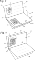
- Fig. 3 shows another embodiment of an identity document 20 according to the invention, such as a passport, in the form of a booklet with a holder page 21 and a neighbouring page 22 that is hingingly connected to the holder page 21 along a hinge line 23.
- the holder page 21 is relatively stiff and has a card-like shape. It can be formed of plastics, polycarbonate, paper or a laminate thereof and has an opaque area 24 and a transparent window 25.
- the transparent window 25 can be made of the same material as the laser image layer 10 in Fig. 2 and has two laser engraved images A,B.
- the colour image C is printed, in an image area 26.
- the colour image in image area 26 and the laser engraved images A,B are oriented in landscape position.
- the portrait in the transparent window 25 is the mirror image of colour image C and the transparent window is viewed on its rear side, on which no lens structure is present.
- the two-dimensional colour image C can be viewed by an inspection person, by hinging the holder page 21 into the position as shown in fig. 3 in a conventional manner.
- the 3D image A,B can be viewed in superposition with the colour image C, as shown in fig. 4 .
- the image area 26 is located in such a position that upon hinging of the holder page 21 around hinge line 23, the window 25 is superimposed on the image area 26.
- the image area 26 and colour image C are visible from the reverse side 27 of the holder page 21 through the transparent window 25.
- the transparent window 25 is provided with a cylindrical lens structure of the type shown in fig. 2 .
- a three-dimensional colour photograph is presented to the inspecting person.
- the holder page 21 and the neighbouring page 22 may be combined with multiple pages 28 to form an official document such as a passport.
- Fig 5 schematically shows the two portrait images 31,32 depicting the holder at slightly different angles, for instance at an angular difference of between 5 0 and 10 0 for viewing of the laser engraved images A,B at viewing distances of between 30 cm and 70 cm.
- the portrait images 31,32 may be made from the holder using a special camera, or may derived from a single photograph of the holder by image processing in a computer, for instance on the basis of the colour portrait image C.
- the portrait images 31, 32 are imaged in the substrate as sets of image lines a1-an and b1-bn that form the basis for the laser engraved images A,B.
- the image lines are scanned by a laser beam into the laser sensitive material and are grouped (a1,b1), (a2,b2)..(an,bn) below the cylindrical lenses into the laser sensitive layer to form three-dimensional image 33, one eye viewing the image A and the other eye simultaneously viewing image B to obtain a stereoscopic image.
- the laser engraved images A,B are superimposed on the colour image 34 so that they are viewed in combination.
- the images A, B are viewed with respective eyes by an observer to form a stereoscopic or three-dimensional image and the colour image C is viewed in a regular two-dimensional manner with both eyes of an inspecting person.
- the focal length h of the lenses 13,14 of the lens array 12 may be about 250 ⁇ m and the width Wl of the cylindrical lenses may be 80 ⁇ m.
- the width of the laser engraved images lines15,16 may be about 15 ⁇ m.
- the distance d of the colour pixels from the focal plane 17 is between about 25 ⁇ m and 1,25 mm.
- Fig 8a shows the printing stage of a colour image C onto a substrate 50.
- the colour image C is stored in digital form in the memory of an image-processing unit 51.
- the image-processing unit 51 provides the digital image data of the colour image C to print control unit 52 that controls the printing unit 53 applying colour pixels 54 onto the substrate 50.
- Fig 8b shows the lamination stage in which the printed substrate 50 is combined with a laser image layer 55 comprising the lenticular array 56 of cylindrical lenses.
- Fig. 8c shows the laser engraving stage in which the image-processing unit 51 provides image data of line images A,B to the laser control unit 57.
- the laser control unit 57 controls the intensity and the position of laser 58, the laser beam 59 of which is focussed by the lenticular array 56 in the image plane 61 of the laser image layer 55 to form sets of grey scale image lines 60.
- Fig 9a shows the printing stage that is carried out independently of the laser engraving stage of the laser image layer 55 that is shown in Fig 9b .
- the laser engraving stage may be carried out at a different moment and/or at a different location from the printing stage.
- Fig. 9c shows the combination of the engraved laser image layer 55 and the printed substrate 50. This combination may be in the form of a lamination process or may be in the form of a hinging superposition of the laser image layer 55 and the substrate 50 in the manner described in relation to Fig. 10 .
- Fig 10 a shows an embodiment wherein the laser engraved image layer 55 is part of a transparent window 68 in a holder page 62.
- the transparent window 68 may be of similar size as the image layer 55 or may be larger.
- the printed substrate 50 is formed by a surface area of an adjacent page 63.
- the pages 62, 63 are placed with their sides 64,65 in close proximity or in contact and are interconnected via a hinging connecting strip 66, as can be seen in Fig. 10b , to be hingeable along hinge line 67.
- the laser engraved image layer 55 can be seen, in combination with the underlying printed substrate 50 through the transparent window 68 from the rear side 69 of the holder page 62.
Landscapes
- Physics & Mathematics (AREA)
- General Physics & Mathematics (AREA)
- Optics & Photonics (AREA)
- Health & Medical Sciences (AREA)
- Electromagnetism (AREA)
- General Health & Medical Sciences (AREA)
- Toxicology (AREA)
- Engineering & Computer Science (AREA)
- Manufacturing & Machinery (AREA)
- Credit Cards Or The Like (AREA)
- Printing Methods (AREA)
- Stereoscopic And Panoramic Photography (AREA)
Claims (5)
- Identifikationsstruktur (1) mit einem Portraitbild (3) eines Inhabers, wobei die Identifikationsstruktur aufweist:- ein Substrat (8, 50),- eine laserempfindliche Schicht (11, 55) und- eine Linsenmatrix (12, 56), die über der laserempfindlichen Schicht (11, 55) liegt, wobei das Substrat (8, 50) ein gedrucktes Muster (9, 54) umfasst,die laserempfindliche Schicht ein lasergraviertes Bildmuster (15, 15'; 16, 16') umfasst, wobei das lasergravierte Bildmuster (15, 15'; 16, 16') ein dreidimensionales Portraitbild (A, B) des Inhabers bildet, und das gedruckte Muster (9, 54) ein zweidimensionales Farbmuster (C) des Portraitbildes des Inhabers bildet,wobei in einer einzelnen senkrechten Betrachtungsposition des Substrats das zweidimensionale Farbmuster (C) und das dreidimensionale Portraitbild (A, B) so eingerichtet sind, dass sie gleichzeitig in einer übereinander liegenden Weise als dreidimensionales Farbportrait gesehen werden, undwobei das lasergravierte Bildmuster (15, 15'; 16, 16') aus mindestens zwei Portraitbildern (A, B) in verschiedenen Winkeln gebildet ist, wobei jedes Bild aus Bildlinien (a1, an; b1, bn) gebildet ist, undwobei die Bildlinien der mindestens zwei Portraitbilder verschachtelt und zu Sätzen (a1, b1), ..., (an, bn) von Bildlinien gruppiert sind, die sich unter jeweiligen zylindrischen Linsen (13, 14) der Linsenmatrix (12, 56) befinden, so dass ein lasergraviertes Portraitbild (B) in ein rechtes Auge (7) eines Betrachters (5) abgebildet wird, und das andere lasergravierte Portraitbild (A) in ein linkes Auge (6) des Betrachters (5) abgebildet wird,wobei das Farbmuster (C) dem Farbbild des Inhabers entspricht, das durch die Linsen (13, 14) in beide Augen (6, 7) des Betrachters (5) abgebildet wird, dadurch gekennzeichnet, dass die laserempfindliche Schicht (11, 55) und die Linsenmatrix (12, 56) eine integrale Laserbildschicht (10, 55) bilden, die mindestens in den Bereichen der Linsen ein transparentes Fenster (25, 68) aufweist, wobei die Laserbildschicht (10, 55) scharnierartig mit dem Substrat (8, 50) verbunden ist, das dreidimensionale lasergravierte Portrait (A; B) sich in dem transparenten Fenster befindet, das dreidimensionale Bild (A, B) und das Farbmuster (C) separat betrachtbar sind, indem die Laserbildschicht (10, 55) von dem Substrat (8, 50) weggeklappt wird, und in Kombination durch Klappen der Laserbildschicht (10, 55) gegen das Substrat (8, 50) betrachtbar sind, so dass das transparente Fenster (25, 68) und das Farbmuster (C) übereinander liegen.
- Identifikationsstruktur (1) nach Anspruch 1, wobei das Farbmuster (C) aus Pixeln (9, 54) mit einer Breite (Wc) in einer Richtung quer zu einer Längsrichtung der zylindrischen Linsen (13, 14) gebildet ist, die größer als eine Breite (WI) der Linsen ist, vorzugsweise größer als die Breite von 2 Linsen.
- Identifikationsstruktur (1) nach Anspruch 1 oder 2, wobei die Laserbildschicht (10) die laserempfindliche Schicht (11, 55) und die darüber befindliche Linsenmatrix (12, 56) umfasst, wobei sich die Laserbildschicht (10) oben auf dem Substrat (8, 50) befindet.
- Identifikationsstruktur (1) nach Anspruch 1, 2 oder 3, wobei die Linsenmatrix (12, 56) eine Fokaldistanz h aufweist, das lasergravierte Bildmuster (15, 15'; 16, 16') sich an oder nahe einer Fokalebene (17) der Linsenmatrix befindet, das Farbmuster (9, 54) in einer Distanz d von der Fokalebene (17) gedruckt ist, wobei d mindestens 0,1*h ist, vorzugsweise mindestens 0,3*h, wie zwischen 3*h und 5*h.
- Verfahren zur Fertigung einer Identifikationsstruktur (1), umfassend die Schritte:- Bereitstellen eines Farbportraitphotos eines Inhabers,- Bereitstellen von zwei Sätzen von verschachtelten Bildlinien, wovon jeder Satz ein Portraitphoto (A, B) des Inhabers in einem unterschiedlichen Winkel bildet,- Drucken eines Farbmusters (C), das dem Farbportrait entspricht, auf ein Substrat (8, 50),- Bereitstellen einer Laserbildschicht (10, 55), die eine laserempfindliche Schicht (11) und eine darüber befindliche Linsenstruktur (12, 56) umfasst, die zylindrische Linsen (13, 14) umfasst,- Lasergravieren der beiden Sätze (a1, b1), ... , (an, bn) von Bildlinien in die laserempfindliche Schicht (11) durch die Linsenstruktur (12, 56) hindurch und unter jeweilige zylindrische Linsen (13, 14) der Linsenmatrix (12, 56), so dass ein lasergraviertes Portraitbild (B) in ein rechtes Auge (7) eines Betrachters (5) abgebildet wird und das andere lasergravierte Portraitbild (A) in ein linkes Auge (6) des Betrachters (5) abgebildet wird,- Kombinieren des Substrats (8, 50) mit der Laserbildschicht (10, 55) entweder vor oder nach dem Lasergravieren, wobei das Farbmuster (C), das dem Farbbild des Inhabers entspricht, durch die Linsen (13, 14) in beide Augen (6, 7) des Betrachters (5) abgebildet wird, und in einer solchen Weise, dass in einer einzelnen senkrechten Betrachtungsposition des Substrats das zweidimensionale Farbmuster (C) und das dreidimensionale Portraitbild (A, B) gleichzeitig in einer übereinander liegenden Weise als dreidimensionales Farbportraitbild betrachtet werden können,- Verbinden der Laserbildschicht (10, 55) mit dem Substrat (8, 50) in einer scharnierartigen Weise, damit das lasergravierte Bild (A, B) so über das Farbmuster (C) gelegt werden kann, dass sie gemeinsam durch einen Benutzer betrachtet werden, wobei das lasergravierte Bild (A, B) und das Farbmuster (C) individuell betrachtbar sind, indem die Laserbildschicht (10, 55) von dem Substrat (8, 50) weggeklappt wird.
Applications Claiming Priority (2)
| Application Number | Priority Date | Filing Date | Title |
|---|---|---|---|
| NL2018474A NL2018474B1 (en) | 2017-03-06 | 2017-03-06 | Security document with a 3D colour photograph |
| PCT/NL2018/050138 WO2018164574A1 (en) | 2017-03-06 | 2018-03-06 | Security document with a 3d colour photograph |
Publications (3)
| Publication Number | Publication Date |
|---|---|
| EP3592570A1 EP3592570A1 (de) | 2020-01-15 |
| EP3592570B1 true EP3592570B1 (de) | 2024-01-10 |
| EP3592570C0 EP3592570C0 (de) | 2024-01-10 |
Family
ID=58548811
Family Applications (1)
| Application Number | Title | Priority Date | Filing Date |
|---|---|---|---|
| EP18718009.6A Active EP3592570B1 (de) | 2017-03-06 | 2018-03-06 | Sicherheitsdokument mit einem 3d-farbfoto |
Country Status (5)
| Country | Link |
|---|---|
| US (1) | US11052697B2 (de) |
| EP (1) | EP3592570B1 (de) |
| NL (1) | NL2018474B1 (de) |
| PL (1) | PL3592570T3 (de) |
| WO (1) | WO2018164574A1 (de) |
Families Citing this family (7)
| Publication number | Priority date | Publication date | Assignee | Title |
|---|---|---|---|---|
| EP3972851B1 (de) | 2019-05-20 | 2024-02-28 | Crane & Co., Inc. | Eine sicherheitsvorrichtung mit nanopartikeln zur einstellung des brechungsindexes von schichten einer polymermatrix zur optimierung des mikrooptischen fokus |
| EP3763540B1 (de) * | 2019-07-08 | 2022-07-06 | IAI Industrial systems B.V. | Verfahren zur herstellung einer karte |
| EP4132799A4 (de) * | 2020-04-07 | 2024-04-10 | Entrust Corporation | Lasertexturierte oberfläche für identifikationsdokumente |
| DE102021002225A1 (de) * | 2021-04-27 | 2022-10-27 | Giesecke+Devrient Mobile Security Gmbh | Sicherheitsmerkmal für ein Wertdokument, Wertdokument und Verfahren zur Herstellung eines Sicherheitsmerkmals |
| US12254795B2 (en) * | 2021-12-10 | 2025-03-18 | International Business Machines Corporation | Display of security information based on splitting into images viewable at a certain reading distance |
| FR3135917B1 (fr) | 2022-05-24 | 2024-04-12 | Idemia France | Procédé de fabrication d'un document d'identité, document d'identité et procédé d'authentification d'un tel document d’identité |
| DE102023127661A1 (de) * | 2023-10-10 | 2025-04-10 | Giesecke+Devrient ePayments GmbH | Verfahren und Herstellungsvorrichtung zur Herstellung eines dreidimensionalen Bildes auf einem Trägerkörper |
Family Cites Families (6)
| Publication number | Priority date | Publication date | Assignee | Title |
|---|---|---|---|---|
| EP0219012B1 (de) | 1985-10-15 | 1993-01-20 | GAO Gesellschaft für Automation und Organisation mbH | Datenträger mit einem optischen Echtheitsmerkmal sowie Verfahren zur Herstellung und Prüfung des Datenträgers |
| DE102005028162A1 (de) * | 2005-02-18 | 2006-12-28 | Giesecke & Devrient Gmbh | Sicherheitselement und Verfahren zu seiner Herstellung |
| NL1028776C2 (nl) | 2005-04-14 | 2006-10-20 | Sdu Identification Bv | Identificatie en werkwijze voor het vervaardigen daarvan. |
| NL2004481C2 (nl) | 2010-03-31 | 2011-10-04 | Sagem Identification B V | Werkwijze voor het vervaardigen van een driedimensionale afbeelding op basis van berekende beeldrotaties. |
| NL2011352C2 (en) | 2013-08-29 | 2015-03-10 | Morpho B V | Identification assembly for an identity document. |
| NL2014520B1 (en) * | 2015-03-25 | 2017-01-19 | Morpho Bv | Method of providing an imprinted security feature. |
-
2017
- 2017-03-06 NL NL2018474A patent/NL2018474B1/en active
-
2018
- 2018-03-06 WO PCT/NL2018/050138 patent/WO2018164574A1/en not_active Ceased
- 2018-03-06 PL PL18718009.6T patent/PL3592570T3/pl unknown
- 2018-03-06 EP EP18718009.6A patent/EP3592570B1/de active Active
- 2018-03-06 US US16/491,607 patent/US11052697B2/en active Active
Also Published As
| Publication number | Publication date |
|---|---|
| EP3592570A1 (de) | 2020-01-15 |
| PL3592570T3 (pl) | 2024-07-29 |
| US11052697B2 (en) | 2021-07-06 |
| NL2018474B1 (en) | 2018-09-21 |
| EP3592570C0 (de) | 2024-01-10 |
| US20200307299A1 (en) | 2020-10-01 |
| WO2018164574A1 (en) | 2018-09-13 |
Similar Documents
| Publication | Publication Date | Title |
|---|---|---|
| EP3592570B1 (de) | Sicherheitsdokument mit einem 3d-farbfoto | |
| US7712673B2 (en) | Identification document with three dimensional image of bearer | |
| CN103998955B (zh) | 个性化安全制品以及鉴别安全制品的方法与验证安全制品的持有人的方法 | |
| US11267276B2 (en) | Optically variable ghost image with embedded data | |
| CN104023991B (zh) | 光学可变防伪元件及具有防伪元件的数据载体与制造方法 | |
| EP1698485A2 (de) | Identifikationsdokument mit linsenrasterartigem Wasserzeichen | |
| AU2017228040B2 (en) | Security object having a dynamic and static window security feature and method for production | |
| JP2010527809A (ja) | 真贋を検出するためのフィルム・エレメントおよびその製造方法 | |
| CN108367586A (zh) | 具有透镜状图像的防伪元件 | |
| EP3838611B1 (de) | Sicherheitselement für einen datenträger, datenträger und verfahren zur herstellung des sicherheitselements und verwendung des sicherheitselements zur herstellung eines datenträgers | |
| US7364085B2 (en) | Identification document with printing that creates moving and three dimensional image effects with pulsed illumination | |
| CN113677537A (zh) | 具有生物特征图像信息的识别文件 | |
| EP2927881A1 (de) | Datenträger | |
| EP1895451A1 (de) | Persönliche identifikationskarte mit zweidimensionalem bild des benutzers | |
| EP3634774B1 (de) | Fälschungssicheres dokument | |
| EP4073576B1 (de) | Lasergravierbares schwebendes bild für sicherheitslaminate | |
| EP4360899A1 (de) | Sicherheitselement für identifikationsdokumente, insbesondere identitätsdokumente, und ein dokument mit einem solchen sicherheitselement | |
| EP2414177B1 (de) | Sicheres ausweisdokument und herstellungsverfahren dafür | |
| US20240354541A1 (en) | Method for the production of a security feature, security feature for a data medium, data medium, and lamination sheet | |
| US20250187362A1 (en) | Identification document and production method | |
| OA16523A (en) | Method for producing a multilayer data carrier and data carrier produced by said method. |
Legal Events
| Date | Code | Title | Description |
|---|---|---|---|
| STAA | Information on the status of an ep patent application or granted ep patent |
Free format text: STATUS: UNKNOWN |
|
| STAA | Information on the status of an ep patent application or granted ep patent |
Free format text: STATUS: THE INTERNATIONAL PUBLICATION HAS BEEN MADE |
|
| PUAI | Public reference made under article 153(3) epc to a published international application that has entered the european phase |
Free format text: ORIGINAL CODE: 0009012 |
|
| STAA | Information on the status of an ep patent application or granted ep patent |
Free format text: STATUS: REQUEST FOR EXAMINATION WAS MADE |
|
| 17P | Request for examination filed |
Effective date: 20190906 |
|
| AK | Designated contracting states |
Kind code of ref document: A1 Designated state(s): AL AT BE BG CH CY CZ DE DK EE ES FI FR GB GR HR HU IE IS IT LI LT LU LV MC MK MT NL NO PL PT RO RS SE SI SK SM TR |
|
| AX | Request for extension of the european patent |
Extension state: BA ME |
|
| DAV | Request for validation of the european patent (deleted) | ||
| DAX | Request for extension of the european patent (deleted) | ||
| STAA | Information on the status of an ep patent application or granted ep patent |
Free format text: STATUS: EXAMINATION IS IN PROGRESS |
|
| 17Q | First examination report despatched |
Effective date: 20200923 |
|
| RAP3 | Party data changed (applicant data changed or rights of an application transferred) |
Owner name: IDEMIA THE NETHERLANDS B.V. |
|
| GRAP | Despatch of communication of intention to grant a patent |
Free format text: ORIGINAL CODE: EPIDOSNIGR1 |
|
| STAA | Information on the status of an ep patent application or granted ep patent |
Free format text: STATUS: GRANT OF PATENT IS INTENDED |
|
| INTG | Intention to grant announced |
Effective date: 20230904 |
|
| P01 | Opt-out of the competence of the unified patent court (upc) registered |
Effective date: 20230914 |
|
| GRAS | Grant fee paid |
Free format text: ORIGINAL CODE: EPIDOSNIGR3 |
|
| GRAA | (expected) grant |
Free format text: ORIGINAL CODE: 0009210 |
|
| STAA | Information on the status of an ep patent application or granted ep patent |
Free format text: STATUS: THE PATENT HAS BEEN GRANTED |
|
| AK | Designated contracting states |
Kind code of ref document: B1 Designated state(s): AL AT BE BG CH CY CZ DE DK EE ES FI FR GB GR HR HU IE IS IT LI LT LU LV MC MK MT NL NO PL PT RO RS SE SI SK SM TR |
|
| REG | Reference to a national code |
Ref country code: GB Ref legal event code: FG4D |
|
| REG | Reference to a national code |
Ref country code: CH Ref legal event code: EP |
|
| REG | Reference to a national code |
Ref country code: DE Ref legal event code: R096 Ref document number: 602018063937 Country of ref document: DE |
|
| REG | Reference to a national code |
Ref country code: IE Ref legal event code: FG4D |
|
| U01 | Request for unitary effect filed |
Effective date: 20240110 |
|
| U07 | Unitary effect registered |
Designated state(s): AT BE BG DE DK EE FI FR IT LT LU LV MT NL PT SE SI Effective date: 20240115 |
|
| P04 | Withdrawal of opt-out of the competence of the unified patent court (upc) registered |
Effective date: 20240110 |
|
| U20 | Renewal fee for the european patent with unitary effect paid |
Year of fee payment: 7 Effective date: 20240220 |
|
| REG | Reference to a national code |
Ref country code: GR Ref legal event code: EP Ref document number: 20240400863 Country of ref document: GR Effective date: 20240516 |
|
| PG25 | Lapsed in a contracting state [announced via postgrant information from national office to epo] |
Ref country code: IS Free format text: LAPSE BECAUSE OF FAILURE TO SUBMIT A TRANSLATION OF THE DESCRIPTION OR TO PAY THE FEE WITHIN THE PRESCRIBED TIME-LIMIT Effective date: 20240510 |
|
| PG25 | Lapsed in a contracting state [announced via postgrant information from national office to epo] |
Ref country code: RS Free format text: LAPSE BECAUSE OF FAILURE TO SUBMIT A TRANSLATION OF THE DESCRIPTION OR TO PAY THE FEE WITHIN THE PRESCRIBED TIME-LIMIT Effective date: 20240410 Ref country code: HR Free format text: LAPSE BECAUSE OF FAILURE TO SUBMIT A TRANSLATION OF THE DESCRIPTION OR TO PAY THE FEE WITHIN THE PRESCRIBED TIME-LIMIT Effective date: 20240110 |
|
| PG25 | Lapsed in a contracting state [announced via postgrant information from national office to epo] |
Ref country code: ES Free format text: LAPSE BECAUSE OF FAILURE TO SUBMIT A TRANSLATION OF THE DESCRIPTION OR TO PAY THE FEE WITHIN THE PRESCRIBED TIME-LIMIT Effective date: 20240110 |
|
| PG25 | Lapsed in a contracting state [announced via postgrant information from national office to epo] |
Ref country code: RS Free format text: LAPSE BECAUSE OF FAILURE TO SUBMIT A TRANSLATION OF THE DESCRIPTION OR TO PAY THE FEE WITHIN THE PRESCRIBED TIME-LIMIT Effective date: 20240410 Ref country code: NO Free format text: LAPSE BECAUSE OF FAILURE TO SUBMIT A TRANSLATION OF THE DESCRIPTION OR TO PAY THE FEE WITHIN THE PRESCRIBED TIME-LIMIT Effective date: 20240410 Ref country code: IS Free format text: LAPSE BECAUSE OF FAILURE TO SUBMIT A TRANSLATION OF THE DESCRIPTION OR TO PAY THE FEE WITHIN THE PRESCRIBED TIME-LIMIT Effective date: 20240510 Ref country code: HR Free format text: LAPSE BECAUSE OF FAILURE TO SUBMIT A TRANSLATION OF THE DESCRIPTION OR TO PAY THE FEE WITHIN THE PRESCRIBED TIME-LIMIT Effective date: 20240110 Ref country code: ES Free format text: LAPSE BECAUSE OF FAILURE TO SUBMIT A TRANSLATION OF THE DESCRIPTION OR TO PAY THE FEE WITHIN THE PRESCRIBED TIME-LIMIT Effective date: 20240110 |
|
| REG | Reference to a national code |
Ref country code: DE Ref legal event code: R097 Ref document number: 602018063937 Country of ref document: DE |
|
| PG25 | Lapsed in a contracting state [announced via postgrant information from national office to epo] |
Ref country code: SM Free format text: LAPSE BECAUSE OF FAILURE TO SUBMIT A TRANSLATION OF THE DESCRIPTION OR TO PAY THE FEE WITHIN THE PRESCRIBED TIME-LIMIT Effective date: 20240110 |
|
| PG25 | Lapsed in a contracting state [announced via postgrant information from national office to epo] |
Ref country code: CZ Free format text: LAPSE BECAUSE OF FAILURE TO SUBMIT A TRANSLATION OF THE DESCRIPTION OR TO PAY THE FEE WITHIN THE PRESCRIBED TIME-LIMIT Effective date: 20240110 |
|
| PG25 | Lapsed in a contracting state [announced via postgrant information from national office to epo] |
Ref country code: SK Free format text: LAPSE BECAUSE OF FAILURE TO SUBMIT A TRANSLATION OF THE DESCRIPTION OR TO PAY THE FEE WITHIN THE PRESCRIBED TIME-LIMIT Effective date: 20240110 |
|
| PG25 | Lapsed in a contracting state [announced via postgrant information from national office to epo] |
Ref country code: SM Free format text: LAPSE BECAUSE OF FAILURE TO SUBMIT A TRANSLATION OF THE DESCRIPTION OR TO PAY THE FEE WITHIN THE PRESCRIBED TIME-LIMIT Effective date: 20240110 Ref country code: SK Free format text: LAPSE BECAUSE OF FAILURE TO SUBMIT A TRANSLATION OF THE DESCRIPTION OR TO PAY THE FEE WITHIN THE PRESCRIBED TIME-LIMIT Effective date: 20240110 Ref country code: RO Free format text: LAPSE BECAUSE OF FAILURE TO SUBMIT A TRANSLATION OF THE DESCRIPTION OR TO PAY THE FEE WITHIN THE PRESCRIBED TIME-LIMIT Effective date: 20240110 Ref country code: CZ Free format text: LAPSE BECAUSE OF FAILURE TO SUBMIT A TRANSLATION OF THE DESCRIPTION OR TO PAY THE FEE WITHIN THE PRESCRIBED TIME-LIMIT Effective date: 20240110 |
|
| REG | Reference to a national code |
Ref country code: CH Ref legal event code: PL |
|
| PLBE | No opposition filed within time limit |
Free format text: ORIGINAL CODE: 0009261 |
|
| STAA | Information on the status of an ep patent application or granted ep patent |
Free format text: STATUS: NO OPPOSITION FILED WITHIN TIME LIMIT |
|
| PG25 | Lapsed in a contracting state [announced via postgrant information from national office to epo] |
Ref country code: MC Free format text: LAPSE BECAUSE OF FAILURE TO SUBMIT A TRANSLATION OF THE DESCRIPTION OR TO PAY THE FEE WITHIN THE PRESCRIBED TIME-LIMIT Effective date: 20240110 |
|
| PG25 | Lapsed in a contracting state [announced via postgrant information from national office to epo] |
Ref country code: MC Free format text: LAPSE BECAUSE OF FAILURE TO SUBMIT A TRANSLATION OF THE DESCRIPTION OR TO PAY THE FEE WITHIN THE PRESCRIBED TIME-LIMIT Effective date: 20240110 |
|
| 26N | No opposition filed |
Effective date: 20241011 |
|
| GBPC | Gb: european patent ceased through non-payment of renewal fee |
Effective date: 20240410 |
|
| P05 | Withdrawal of opt-out of the competence of the unified patent court (upc) changed |
Free format text: CASE NUMBER: APP_1432/2024 Effective date: 20240115 |
|
| PG25 | Lapsed in a contracting state [announced via postgrant information from national office to epo] |
Ref country code: GB Free format text: LAPSE BECAUSE OF NON-PAYMENT OF DUE FEES Effective date: 20240410 |
|
| PG25 | Lapsed in a contracting state [announced via postgrant information from national office to epo] |
Ref country code: IE Free format text: LAPSE BECAUSE OF NON-PAYMENT OF DUE FEES Effective date: 20240306 |
|
| PG25 | Lapsed in a contracting state [announced via postgrant information from national office to epo] |
Ref country code: IE Free format text: LAPSE BECAUSE OF NON-PAYMENT OF DUE FEES Effective date: 20240306 Ref country code: GB Free format text: LAPSE BECAUSE OF NON-PAYMENT OF DUE FEES Effective date: 20240410 Ref country code: CH Free format text: LAPSE BECAUSE OF NON-PAYMENT OF DUE FEES Effective date: 20240331 |
|
| U20 | Renewal fee for the european patent with unitary effect paid |
Year of fee payment: 8 Effective date: 20250210 |
|
| U1N | Appointed representative for the unitary patent procedure changed after the registration of the unitary effect |
Representative=s name: SANTARELLI; FR |
|
| PGFP | Annual fee paid to national office [announced via postgrant information from national office to epo] |
Ref country code: GR Payment date: 20250220 Year of fee payment: 8 |
|
| PGFP | Annual fee paid to national office [announced via postgrant information from national office to epo] |
Ref country code: PL Payment date: 20250303 Year of fee payment: 8 |
|
| PG25 | Lapsed in a contracting state [announced via postgrant information from national office to epo] |
Ref country code: CY Free format text: LAPSE BECAUSE OF FAILURE TO SUBMIT A TRANSLATION OF THE DESCRIPTION OR TO PAY THE FEE WITHIN THE PRESCRIBED TIME-LIMIT; INVALID AB INITIO Effective date: 20180306 |
|
| PG25 | Lapsed in a contracting state [announced via postgrant information from national office to epo] |
Ref country code: HU Free format text: LAPSE BECAUSE OF FAILURE TO SUBMIT A TRANSLATION OF THE DESCRIPTION OR TO PAY THE FEE WITHIN THE PRESCRIBED TIME-LIMIT; INVALID AB INITIO Effective date: 20180306 |
|
| PG25 | Lapsed in a contracting state [announced via postgrant information from national office to epo] |
Ref country code: TR Free format text: LAPSE BECAUSE OF FAILURE TO SUBMIT A TRANSLATION OF THE DESCRIPTION OR TO PAY THE FEE WITHIN THE PRESCRIBED TIME-LIMIT Effective date: 20240110 |