EP3592128B1 - Distribution machine - Google Patents
Distribution machine Download PDFInfo
- Publication number
- EP3592128B1 EP3592128B1 EP18712077.9A EP18712077A EP3592128B1 EP 3592128 B1 EP3592128 B1 EP 3592128B1 EP 18712077 A EP18712077 A EP 18712077A EP 3592128 B1 EP3592128 B1 EP 3592128B1
- Authority
- EP
- European Patent Office
- Prior art keywords
- threaded spindle
- metering
- metering slide
- rotary drive
- distributing machine
- Prior art date
- Legal status (The legal status is an assumption and is not a legal conclusion. Google has not performed a legal analysis and makes no representation as to the accuracy of the status listed.)
- Active
Links
- 238000009826 distribution Methods 0.000 title description 39
- 239000000463 material Substances 0.000 claims description 30
- 230000005540 biological transmission Effects 0.000 claims description 12
- 238000006073 displacement reaction Methods 0.000 claims description 9
- 230000007480 spreading Effects 0.000 claims description 6
- 238000003892 spreading Methods 0.000 claims description 6
- 239000011236 particulate material Substances 0.000 claims description 4
- 238000009331 sowing Methods 0.000 claims description 2
- 239000012254 powdered material Substances 0.000 claims 1
- 238000001514 detection method Methods 0.000 description 14
- 238000013461 design Methods 0.000 description 9
- 239000002245 particle Substances 0.000 description 9
- 230000001105 regulatory effect Effects 0.000 description 7
- 239000003337 fertilizer Substances 0.000 description 6
- 241000209035 Ilex Species 0.000 description 5
- 150000003839 salts Chemical class 0.000 description 5
- 230000007797 corrosion Effects 0.000 description 4
- 238000005260 corrosion Methods 0.000 description 4
- 230000006378 damage Effects 0.000 description 4
- 239000012535 impurity Substances 0.000 description 4
- 210000000056 organ Anatomy 0.000 description 4
- 230000008901 benefit Effects 0.000 description 3
- 230000015556 catabolic process Effects 0.000 description 3
- 238000004140 cleaning Methods 0.000 description 3
- 230000008878 coupling Effects 0.000 description 3
- 238000010168 coupling process Methods 0.000 description 3
- 238000005859 coupling reaction Methods 0.000 description 3
- 239000000428 dust Substances 0.000 description 3
- 230000007613 environmental effect Effects 0.000 description 3
- 230000007257 malfunction Effects 0.000 description 3
- 230000001932 seasonal effect Effects 0.000 description 3
- 238000010276 construction Methods 0.000 description 2
- 238000011109 contamination Methods 0.000 description 2
- 238000005265 energy consumption Methods 0.000 description 2
- 239000012530 fluid Substances 0.000 description 2
- 238000001746 injection moulding Methods 0.000 description 2
- 229910052500 inorganic mineral Inorganic materials 0.000 description 2
- 238000012423 maintenance Methods 0.000 description 2
- 238000004519 manufacturing process Methods 0.000 description 2
- 239000002184 metal Substances 0.000 description 2
- 238000000034 method Methods 0.000 description 2
- 239000011707 mineral Substances 0.000 description 2
- 239000000843 powder Substances 0.000 description 2
- 230000008569 process Effects 0.000 description 2
- 238000007789 sealing Methods 0.000 description 2
- 239000007787 solid Substances 0.000 description 2
- 235000014676 Phragmites communis Nutrition 0.000 description 1
- 208000012886 Vertigo Diseases 0.000 description 1
- 230000004308 accommodation Effects 0.000 description 1
- 230000009471 action Effects 0.000 description 1
- 239000000853 adhesive Substances 0.000 description 1
- 230000001070 adhesive effect Effects 0.000 description 1
- 230000033228 biological regulation Effects 0.000 description 1
- 239000003251 chemically resistant material Substances 0.000 description 1
- 230000000295 complement effect Effects 0.000 description 1
- 239000000356 contaminant Substances 0.000 description 1
- 230000006735 deficit Effects 0.000 description 1
- 238000011161 development Methods 0.000 description 1
- 230000000694 effects Effects 0.000 description 1
- 230000004720 fertilization Effects 0.000 description 1
- 239000010419 fine particle Substances 0.000 description 1
- 230000009760 functional impairment Effects 0.000 description 1
- 230000001771 impaired effect Effects 0.000 description 1
- 230000006698 induction Effects 0.000 description 1
- 239000007788 liquid Substances 0.000 description 1
- 230000007774 longterm Effects 0.000 description 1
- 239000007769 metal material Substances 0.000 description 1
- 230000000149 penetrating effect Effects 0.000 description 1
- 230000000704 physical effect Effects 0.000 description 1
- 230000000750 progressive effect Effects 0.000 description 1
- 230000001681 protective effect Effects 0.000 description 1
- 230000001012 protector Effects 0.000 description 1
- 230000009467 reduction Effects 0.000 description 1
- 239000004576 sand Substances 0.000 description 1
- 230000035939 shock Effects 0.000 description 1
- 229910001220 stainless steel Inorganic materials 0.000 description 1
- 239000010935 stainless steel Substances 0.000 description 1
- 239000000126 substance Substances 0.000 description 1
- 238000013519 translation Methods 0.000 description 1
Images


Classifications
-
- A—HUMAN NECESSITIES
- A01—AGRICULTURE; FORESTRY; ANIMAL HUSBANDRY; HUNTING; TRAPPING; FISHING
- A01C—PLANTING; SOWING; FERTILISING
- A01C17/00—Fertilisers or seeders with centrifugal wheels
- A01C17/006—Regulating or dosing devices
- A01C17/008—Devices controlling the quantity or the distribution pattern
-
- A—HUMAN NECESSITIES
- A01—AGRICULTURE; FORESTRY; ANIMAL HUSBANDRY; HUNTING; TRAPPING; FISHING
- A01C—PLANTING; SOWING; FERTILISING
- A01C17/00—Fertilisers or seeders with centrifugal wheels
- A01C17/006—Regulating or dosing devices
-
- A—HUMAN NECESSITIES
- A01—AGRICULTURE; FORESTRY; ANIMAL HUSBANDRY; HUNTING; TRAPPING; FISHING
- A01C—PLANTING; SOWING; FERTILISING
- A01C19/00—Arrangements for driving working parts of fertilisers or seeders
- A01C19/02—Arrangements for driving working parts of fertilisers or seeders by a motor
Description
Die Erfindung betrifft eine Verteilmaschine, insbesondere Streu- und/oder Sämaschine, mit wenigstens einem von einem Tragrahmen getragenen Behälter zur Aufnahme von pulver- und/oder partikelförmigem Verteilgut, wenigstens einer am Boden des Behälters angeordneten Auslauföffnung, einem der Auslauföffnung nachgeordneten Dosierorgan mit einem motorisch angetriebenen, relativ zu der Auslauföffnung verlagerbaren Dosierschieber sowie wenigstens einem dem Dosierorgan nachgeordneten Verteilorgan zum Verteilen des Verteilgutes auf dem Boden, wobei der Antrieb des Dosierschiebers des Dosierorgans eine axialfest gelagerte, mittels eines motorischen Drehantriebs mit axialfester Abtriebswelle drehangetriebene Gewindespindel umfasst, entlang welcher eine mit der Gewindespindel im Eingriff stehende Spindelmutter geführt ist, welche mit dem Dosierschieber oder einem hieran angeordneten Hebelarm in Verbindung steht, um den Dosierschieber durch Rotieren der Gewindespindel zu betätigen.The invention relates to a distributing machine, in particular a spreader and / or seeder, with at least one container carried by a support frame for receiving powder and / or particulate material to be distributed, at least one outlet opening arranged on the bottom of the container, a dosing element downstream of the outlet opening with a motor driven metering slide that can be displaced relative to the outlet opening as well as at least one distribution element arranged downstream of the metering element for distributing the material to be distributed on the floor, the drive of the metering slide of the metering element comprising an axially fixedly mounted, by means of a motorized rotary drive with an axially fixed output shaft, a threaded spindle along which a threaded spindle is connected to the Threaded spindle engaged spindle nut is guided, which is connected to the metering slide or a lever arm arranged thereon in order to actuate the metering slide by rotating the threaded spindle.
Verteilmaschinen der vorgenannten Art sind vornehmlich einerseits in Form von landwirtschaftlichen Streumaschinen zum Ausbringen von pulver- oder partikelförmigen Gut, wie insbesondere Dünger oder Saatgut, in vielfältiger Ausgestaltung bekannt, so beispielsweise in gezogener oder von einem Dreipunkt einer Zugmaschine, wie eines Traktors, aufgenommener Bauart. Derartige Verteilmaschinen umfassen einen das Verteilgut aufnehmenden Behälter, an dessen Boden üblicherweise eine oder zwei Auslauföffnungen angeordnet sind, wobei der jeweiligen Auslauföffnung ein Dosierorgan zugeordnet ist, um das Verteilgut in der gewünschten Menge - oder genauer: mit dem gewünschten Massenstrom - dem Behälter zu entnehmen. Das Dosierorgan umfasst häufig einen - sei es translatorisch oder sei es insbesondere rotatorisch - in Bezug auf die Auslauföffnung verlagerbaren Dosierschieber, welcher mittels eines geeigneten Stellorgans in Form eines Hydraulik- oder Elektrozylinders auf- und zusteuerbar ist, um je nach gewünschter Verteilungsbreite und geforderter Streumenge pro Flächeneinheit des Verteilgutes auf dem Boden, je nach Fahrgeschwindigkeit und je nach den physikalischen Eigenschaften des Verteilgutes, wie beispielsweise dessen Rieselfähigkeit, den gewünschten Massenstrom einstellen zu können. Unterhalb des Dosierorgans befindet sich ein Verteilorgan, mittels welchem das Verteilgut über die gewünschte Arbeitsbreite verteilt wird. Manche Verteilmaschinen sind überdies mit einer Einrichtung zur Verstellung des Aufgabepunktes des Verteilgutes auf das, insbesondere von einer mit Wurfflügeln bestückten Verteilerscheibe gebildete, Verteilorgan ausgestattet, wobei der Aufgabepunkt in Bezug auf die Verteilerscheibe radial (insbesondere zu Vergrößerung/Verkleinerung des Streufächers) und/oder in Umfangsrichtung (insbesondere zum Verdrehen des Streufächers etwa um die Drehachse der Verteilerscheibe) verstellbar sein kann. Eine derartige landwirtschaftliche Verteilmaschine ist beispielsweise in Form eines Zweischeibenstreuers aus der
Andererseits sind gattungsgemäße Verteilmaschinen in Form von Winterdienststreumaschinen bekannt, bei welchen der Behälter vornehmlich zur Aufnahme von in der Regel granulatförmigem Splitt und/oder Streusalz dient, wobei die Funktion einer solchen Winterdienststreumaschine weitestgehend jener der oben beschriebenen landwirtschaftlichen Streumaschine entspricht.On the other hand, generic distribution machines in the form of winter road spreader are known, in which the container is primarily used to hold granular grit and / or road salt, the function of such a winter road spreader largely corresponds to that of the agricultural spreader described above.
Beim Ausbringen des Verteilgutes - sei es in Form von Dünger oder Saatgut auf einem Feld oder sei es in Form von Splitt oder Salz auf einer Straße - werden in aller Regel große Mengen an Partikeln von Erde, Sand, Staub und dergleichen aufgewirbelt, welche insbesondere an die unterhalb des Behälters angeordneten Dosierorgane und deren Stellzylinder gelangen können, wodurch je nach Beschaffenheit und Größe der Partikel die Funktion beeinträchtigt werden kann, sofern sich beispielsweise größere Partikel einschließlich kleiner Steine dort verklemmen. Darüber hinaus neigt insbesondere das Verteilgut, welches gleichfalls in Pulver- oder Partikelform vorliegt, häufig zur Anreicherung an den unterhalb des Behälters befindlichen Dosierorganen bzw. an den zur Betätigung deren Dosierschieber dienenden Stellzylindern, wobei insbesondere die meisten festen Düngemittel wie auch Streusalz einen hygroskopischen Charakter besitzen, so dass sie in Verbindung mit Luftfeuchtigkeit oder gar Regen bzw. Schnee(matsch) agglomerieren und mit fortschreitender Ausbringung zunehmend in mehr oder minder harten Agglomeraten den vorgenannten Funktionsteilen anhaften. Dies gilt insbesondere - wenn auch nicht ausschließlich - dann, wenn die Verteilorgane von Streu- bzw. Verteilerscheiben gebildet sind, die das pulver- oder partikelförmige Gut radial an den Dosierorganen vorbei fortschleudern.When spreading the material - be it in the form of fertilizer or seeds in a field or be it in the form of Grit or salt on a road - large amounts of particles of earth, sand, dust and the like are usually whirled up, which can reach the dosing elements and their adjusting cylinders arranged below the container, whereby the function depending on the nature and size of the particles can be impaired if, for example, larger particles including small stones get stuck there. In addition, the material to be distributed, which is also in powder or particle form, often tends to accumulate on the metering devices located below the container or on the actuating cylinders used to operate their metering slides, with most solid fertilizers and road salt in particular having a hygroscopic character , so that they agglomerate in connection with air humidity or even rain or snow (mud) and, with progressive application, increasingly adhere to the aforementioned functional parts in more or less hard agglomerates. This applies in particular - if not exclusively - when the distribution elements are formed by scattering or distributor disks which hurl the powdery or particulate material radially past the metering elements.
Die
Sofern es sich bei diesen, für den Antrieb des Dosierschiebers der Dosierorgane vorgesehenen Stellzylindern um Hydraulikzylinder handelt, deren translatorische Bewegung der Kolbenstange in den Zylinder hinein und aus diesem heraus mittels geeigneter Hebel(gestänge) in eine translatorische oder in eine rotatorische Bewegung des Dosierschiebers umgesetzt wird, wie sie aufgrund ihres einfachen Anschlusses an das Hydrauliksystem eines Traktors häufig zum Einsatz gelangen, ist es aufgrund der aggressiven Umgebungsbedingungen ferner einerseits erforderlich, zumindest die Kolbenstangen der Hydraulikzylinder aus sehr harten und chemisch resistenten Materialien, wie verchromtem Edelstahl, zu fertigen; andererseits werden sehr hohe Anforderungen an die zur Abdichtung der Kolbenstangen gegen den Zylinder eingesetzten Dichtungselemente gestellt, da die Kolbenstangen während des Betriebs ständig, wenngleich teils nur geringfügig, aus dem Zylinder aus- bzw. in diesen eingeschoben werden, wodurch die Gefahr einer Einschleppung von an der Kolbenstange anhaftenden Fremdkörpern und/oder Feuchtigkeit ins Innere des Hydraulikzylinders besteht. Darüber hinaus sollte sich zur Gewährleistung eines einwandfreien und verschleißarmen Betriebs von Hydraulikzylindern auf deren Kolbenstange ein Ölfilm befinden, welcher jedoch aufgrund seines adhäsiven Charakters andererseits die Gefahr einer Anbackung von Verunreinigungen und somit deren Einschleppung in den internen Ölkreislauf erhöht. Überdies kann die zumindest teilweise aus dem Hydraulikzylinder ausgezogene Kolbenstange auch außerhalb des - bei gattungsgemäßen Verteilmaschinen üblicherweise saisonalen - Betriebs über Monate aggressiven Umgebungsbedingungen ausgesetzt sein, so dass es trotz der aufwändigen und inerten Materialien zur Korrosion kommt. Die
Schließlich stellt sich bei gattungsgemäßen Dosierorganen, welche einen relativ zu der Auslauföffnung des zur Bevorratung des Verteilgutes dienenden Behälters verlagerbaren Dosierschieber aufweisen, im Falle eines Antriebs des Dosierschiebers mittels eines Hydraulikzylinders ein weiteres Problem dahingehend, dass zur Einstellung einer gewünschten Dosierrate (entsprechend einer bestimmten Öffnungsstellung des Dosierschiebers relativ zu der Auslauföffnung) mittels einer Skala und einem Fixierungssystem ein mit der gewünschten Öffnungsstellung des Dosierschiebers korrespondierender Anschlag eingestellt werden muss, gegen welchen der Hydraulikzylinder dann anfahren kann. Auf diese Weise lässt sich zwar eine bestimmte Dosierrate bzw. ein bestimmter Massenstrom an Verteilgut einstellen, doch lässt sich diese(r) nicht verändern, wenn sich beispielsweise die Fahrgeschwindigkeit gegenüber der ursprünglich einkalkulierten Geschwindigkeit ändert (und folglich eine höhere oder niedrigere Dosierrate vonnöten wäre).Finally, in the case of generic metering devices which have a metering slide that can be displaced relative to the outlet opening of the container serving to store the distribution material, if the metering slide is driven by means of a hydraulic cylinder, a further problem arises in that to set a desired metering rate (corresponding to a specific opening position of the Metering slide relative to the outlet opening) by means of a scale and a fixing system, a stop corresponding to the desired opening position of the metering slide must be set, against which the hydraulic cylinder can then move. In this way, a certain dosing rate or a certain mass flow of material to be distributed can be set, but this (s) cannot be changed if, for example, the driving speed changes from the originally calculated speed (and consequently a higher or lower dosing rate would be necessary) .
Aus diesem Grund machen moderne Verteilmaschinen anstelle von Hydraulikzylindern häufig von Elektrozylindern zum Antrieb der Dosierschieber der Dosierorgane Gebrauch, deren translatorische Bewegung der Kolbenstange in den Zylinder hinein und aus diesem heraus in entsprechender Weise wie im Falle von Hydraulikzylindern mittels geeigneter Hebel(gestänge) in eine translatorische oder insbesondere in eine rotatorische Bewegung des Dosierschiebers umgesetzt wird. Derartige Elektrozylinder sind häufig mit Wegsensoren ausgestattet, um die genaue Auszugsposition der Kolbenstange in Bezug auf den Zylinder, welche repräsentativ für die Öffnungsstellung des Dosierorgans ist, zu erfassen und insbesondere steuerungstechnisch zu nutzen (
Allerdings stellen die bei gattungsgemäßen Verteilmaschinen auf die Stellorgane der Dosierorgane einwirkenden aggressiven Stäube oder Partikel von Mineraldünger, Salz oder auch anderen Verunreinigungen von außen auch im Falle von Elektrozylindern ein nicht unerhebliches Funktionsproblem dar. So entsteht beispielsweise beim Einziehen der Kolbenstange in bzw. beim Ausschieben derselben aus dem Elektrozylinder ein Über- bzw. Unterdruck im Innern des Zylinders, welcher bei gattungsfremden Applikationen zwar mittels geeigneter Ventile nach außen kompensiert werden kann, was im Falle von Verteilmaschinen jedoch schwerlich möglich ist, weil durch das Ventil Umgebungsstäube und/oder Feuchtigkeit in den Zylinder eindringen und zu Korrosion führen könnten. Andererseits birgt der im ausgeschobenen Zustand der Kolbenstange im Innern des Zylinders herrschende Unterdruck wiederum die Gefahr eines Einsaugens von Staub und/oder Feuchtigkeit, so dass - wie auch im Falle von Hydraulikzylindern - eine sehr hohe Dichtigkeit gewährleistet sein muss, was praktisch nur mit sehr kostspieligen Spezialdichtungen möglich ist. Sofern sich an der Kolbenstange verkrustete bzw. verhärtete Agglomerate gebildet haben, müssen diese ferner durch wirksame mechanische Abtreifer sicher zerstört und gelöst werden, um derartige Spezialdichtungen nicht zu beschädigen und die hohe Dichtigkeit aufrechtzuerhalten. Die hohe Dichtigkeit ist dabei auch im Hinblick darauf gerade bei Elektrozylindern von größter Bedeutung, weil im Innern des Zylinders üblicherweise das Wegsensorsystem zur Erfassung der aktuellen Auszugsposition der Kolbenstange untergebracht ist. Im Falle von eingedrungenen - festen und/oder flüssigen - Verunreinigungen leiden derartige Wegsensoren jedoch Schaden, sei es infolge mechanischer Beeinträchtigung oder sei es infolge Korrosion, so dass die Positionserfassung ungenau oder gänzlich unwirksam wird und sich folglich Fehlfunktionen hinsichtlich der Dosierrate ergeben.However, the aggressive dusts or particles of mineral fertilizer, salt or other external impurities acting on the actuators of the metering devices in generic distributing machines also represent a not inconsiderable functional problem in the case of electric cylinders. For example, when the piston rod is drawn in or pushed out From the electric cylinder, an overpressure or underpressure inside the cylinder, which in non-generic applications can be compensated for outwards using suitable valves, but this is hardly possible in the case of distribution machines because the valve causes ambient dust and / or moisture to enter the cylinder penetrate and lead to corrosion. On the other hand, the negative pressure prevailing inside the cylinder when the piston rod is pushed out again harbors the risk of dust and / or moisture being sucked in, so that - as in the case of hydraulic cylinders - a very high level of tightness must be guaranteed, which in practice only takes very expensive Special seals is possible. If encrusted or hardened agglomerates have formed on the piston rod, they must also be safely destroyed and loosened by effective mechanical wipers in order not to damage such special seals and to maintain the high level of tightness. The high level of tightness is also of the utmost importance, especially with electric cylinders, because the displacement sensor system for detecting the current extension position of the piston rod is usually housed inside the cylinder. In the case of penetrated - solid and / or liquid - impurities, however, such displacement sensors suffer damage, be it due to mechanical ones Impairment or due to corrosion, so that the position detection becomes imprecise or completely ineffective and consequently malfunctions with regard to the dosing rate result.
Entsprechendes gilt weitestgehend für den Fall von elektromotorischen Spindelantrieben zur Verlagerung des Dosierschiebers des Dosierorgans, welche gleichfalls von ineinander teleskopierbaren Teilen Gebrauch machen und bei welchen die aus dem Motorgehäuse translatorisch ein- und ausfahrbare Spindel wiederum Gefahr läuft, partikuläre oder fluide Verunreinigungen in das Motorgehäuse einzutragen und den Elektromotor selbst oder dessen Sensoren zu beschädigen, wobei sich die genannten Verunreinigungen in dem spiralförmigen Spindelgewinde besonders hartnäckig ablagern und bei fortwährendem Betrieb bzw. fortwährendem Hinein- und Hinausfahren der Spindel in das bzw. aus dem Motorgehäuse praktisch nicht mehr gelöst werden können. Ein derartiger, mit einem Getriebe versehener elektromotorischer Spindelantrieb eines drehbar gelagerten Dosierschiebers eines Dosierorgans eines Scheibenstreuers ist beispielsweise der
Bei sämtlichen, durch die obigen Probleme ausgelösten Funktionsbeeinträchtigungen ergibt sich zwangsläufig ein Arbeitsstillstand der Verteilmaschine, welche in der Regel nur schwer oder gar nicht in eine Art manuellen Notbetrieb versetzt werden kann. Nachdem gattungsgemäße Verteilmaschinen aber fast ausschließlich saisonal eingesetzt werden und für ihren notwendigen Einsatz üblicherweise ein nur kurzes Zeitfenster zur Verfügung steht (sei es im Falle einer saisonalen Düngung bei einem vorgegebenen Zustand der Bepflanzung oder sei es bei plötzlich auftretendem Schneefall), müssen derartige Ausfälle der Verteilmaschine so weit wie überhaupt möglich vermieden werden.With all of the functional impairments caused by the above problems, the distribution machine inevitably comes to a standstill, which as a rule can only be switched to a type of manual emergency operation with difficulty or not at all. However, since generic distributing machines are used almost exclusively seasonally and there is usually only a short time window available for their necessary use (be it in the case of seasonal fertilization with a given state of the planting or be it with sudden snowfall), such breakdowns of the distributing machine must be avoided as much as possible.
Als weiteres Problem der zur Betätigung des Dosierschiebers gattungsgemäßer Dosierorgane verwendeten Elektrozylindern, welche von ineinander teleskopierbaren Teilen Gebrauch machen, kommt hinzu, dass aufgrund zunehmender Größe (bzw. zunehmender Arbeitsbreiten) und zunehmenden Fahrgeschwindigkeiten sowie zunehmenden Automatisierungsprozessen immer höhere Einzugs- und Ausschubgeschwindigkeiten der Kolbenstange bzw. der Verstellspindel in den und aus dem Elektrozylinder erforderlich sind. Nachdem der Wirkungsgrad von Elektrozylindern aufgrund des für den üblicherweise reibungsintensiven Betrieb erheblichen Kraftaufwandes relativ gering ist, besteht folglich ein immer größerer Bedarf an zur Verfügung stehender elektrischer Leistung. Dies ist nicht nur im Hinblick auf einen hohen elektrischen Energieverbrauch von Nachteil, sondern insbesondere auch im Hinblick darauf, dass die Elektrozylinder gattungsgemäßer Verteilmaschinen in der Regel von dem Bordnetzsystem der Zugmaschine gespeist werden müssen, wobei sowohl in der Landtechnik als auch bei herkömmlichen Straßenfahrzeugen zumeist nur ein 12 V-Netz zur Verfügung steht. Handelt es sich bei der Verteilmaschine insbesondere um eine solche mit elektrischer bzw. elektronischer Steuerung und/oder Regelung mehrerer Funktionen der Verteilmaschine, so können bis zu sechs elektrische Stellantriebe (jeweils zwei für die Dosierorgane, die gegebenenfalls vorhandenen Einrichtungen zur Verstellung des Aufgabepunktes sowie für gegebenenfalls vorhandene Rührwerke) vorhanden sein, welche beim gleichzeitigen Betrieb gemeinsam mit der Steuer-/Regelelektronik selbst sowie mit einer dieser üblicherweise zugeordneten Bedieneinheit sehr hohe elektrische Leistungen erfordern. Dies kann zu sehr hohen Stromstärken bis hin zu einem Zusammenbruch des Bordnetzes bzw. zu einer Notabschaltung mittels der Sicherungen führen, so dass sich ein Bedarf an einer Erhöhung des schlechten Wirkungsgrades von elektrischen Stellzylindern ergibt.Another problem with the electric cylinders used to actuate the metering slide of the generic metering devices, which make use of parts that can be telescoped into one another, is that, due to increasing size (or increasing working widths) and increasing travel speeds as well as increasing automation processes, ever higher retraction and extension speeds of the piston rod or the adjusting spindle in and out of the electric cylinder are required. Since the efficiency of electric cylinders is relatively low due to the considerable amount of force required for the usually friction-intensive operation, there is consequently an ever greater demand for available electrical power. This is not only a disadvantage with regard to high electrical energy consumption, but also in particular with regard to the fact that the electric cylinders of generic distribution machines usually have to be fed from the on-board network system of the tractor, with both in agricultural engineering and in conventional road vehicles mostly only a 12 V network is available. In particular, if the distribution machine is such with electrical or electronic control and / or regulation of several functions of the distribution machine, up to six electrical actuators (two each for the dosing elements, any devices for adjusting the feed point and any agitators that may be present) can be used together with the control electronics themselves and with an operating unit usually assigned to them, require very high electrical powers. This can lead to very high currents up to a breakdown of the on-board network or to an emergency shutdown by means of the fuses, so that there is a need to increase the poor efficiency of electric actuating cylinders.
Die
Wie bereits erwähnt, sind gattungsgemäße Verteilmaschinen häufig mit Einrichtungen zur Verstellung des Aufgabepunktes des Verteilgutes auf die Verteilorgane ausgestattet, in Bezug auf deren konstruktive Ausgestaltung im Wesentlichen drei Ausführungsvarianten bekannt sind, welche
- eine drehbare Lagerung eines mit der Auslauföffnung aus dem Behälter versehenen Bodens;
- eine koaxial mit dem Verteilorgan drehbare Lagerung einer dem Dosierorgan nachgeordneten Hülse mit einer radialen Aufgabeöffnung auf das Verteilorgan; oder
- eine drehbare oder auch translatorisch verfahrbare Lagerung einer dem Dosierorgan nachgeordneten Rutsche oder Rinne
- a rotatable mounting of a base provided with the outlet opening from the container;
- a bearing, rotatable coaxially with the distribution element, of a sleeve arranged downstream of the dosing element with a radial feed opening onto the distribution element; or
- a rotatable or translationally displaceable mounting of a chute or channel downstream of the dosing element
Der Erfindung liegt die Aufgabe zugrunde, eine Verteilmaschine der eingangs genannten Art auf einfache und kostengünstige Weise dahingehend weiterzubilden, dass unter zumindest weitestgehender Vermeidung der vorgenannten Nacheile auch unter Einwirkung von aggressiven pulver- oder partikelförmigen Stoffen einschließlich Feuchtigkeit bzw. Nässe bei extremen Witterungsbedingungen die Betriebssicherheit des Dosierorgans und insbesondere auch die Verstellgeschwindigkeit seines Dosierschiebers erhöht wird, wobei das Dosierorgan einschließlich des Stellantriebs seines Dosierschiebers vorzugsweise möglichst kompakt ausgebildet sein sollte.The invention is based on the object of developing a distributing machine of the type mentioned at the beginning in a simple and inexpensive manner in such a way that, while avoiding the aforementioned disadvantages as far as possible, even under the action of aggressive powdery or particulate substances including moisture or wetness in extreme weather conditions, the operational safety of the Dosing member and in particular also the adjustment speed of its metering slide is increased, the metering member including the actuator of its metering slide should preferably be designed as compact as possible.
Erfindungsgemäß wird diese Aufgabe bei einer Verteilmaschine der eingangs genannten Art dadurch gelöst, dass der Dosierschieber des Dosierorgans um eine Schwenkachse rotatorisch verlagerbar ist, welche den mit der Auslauföffnung versehenen Boden des Behälters durchsetzt, wobei an der dem Dosierschieber entgegengesetzten Seite des Bodens ein drehfest mit seiner Schwenkachse verbundener Hebelarm mit der Spindelmutter in Verbindung steht.According to the invention, this object is achieved in a dispensing machine of the type mentioned in that the metering slide of the metering member is rotatably displaceable about a pivot axis which penetrates the bottom of the container provided with the outlet opening, with a non-rotatable with its on the side of the bottom opposite the metering slide Swivel axis connected lever arm is connected to the spindle nut.
Die erfindungsgemäße Ausgestaltung der Stellorgane des Dosierschiebers des Dosierorgans mit der mit der axialfesten, aber drehbar gelagerten Gewindespindel im Eingriff stehenden Spindelmutter beseitigt zunächst sämtliche mit den Stellorganen gemäß dem Stand der Technik, welche ineinander teleskopierbare Teile umfassen, verbundenen Problematiken hinsichtlich schädlicher Anbackungen von Verunreinigungen, wie Verteilgutpartikeln, Schmutz und/oder Feuchtigkeit, an deren Kolbenstange oder Verstellspindel, da die axialfest gelagerte Gewindespindel mittels eines rein rotatorisch wirksamen Drehantriebs, dessen Abtriebswelle folglich gleichfalls drehbar, aber axialfest gelagert ist (siehe hierzu auch weiter unten), in Rotation versetzt werden kann und somit keine nennenswerte Gefahr eines Eindringens von Verunreinigungen in den Antriebsmotor besteht, ohne dass für den Antrieb des Dosierschiebers translatorisch ineinander teleskopierbare Teile mit hieran angelenkten Hebeln erforderlich sind. Stattdessen sieht die Erfindung eine Übertragung der rein rotatorischen Bewegung der axialfesten Abtriebswelle des motorischen Drehantriebs auf die gleichfalls axialfest gelagerte Gewindespindel vor, deren mit ihr im Eingriff stehende Spindelmutter diese rotatorische Bewegung in eine translatorische Bewegung entlang der Gewindespindel umsetzt und dabei den Dosierschieber bzw. einen hieran angeordneten Hebelarm mitnimmt, um für verschiedene (teilweise und gänzliche) Öffnungsstellungen des Dosierschiebers sowie zumindest eine Schließstellung desselben zu sorgen, in welcher der Dosierschieber die Auslauföffnung gänzlich verschließt.The inventive design of the control elements of the metering slide of the dosing element with the spindle nut engaged with the axially fixed but rotatably mounted threaded spindle initially eliminates all problems associated with the adjusting elements according to the prior art, which include parts telescoping into one another, with regard to harmful caking of impurities, such as Distribution material particles, dirt and / or moisture on their piston rod or adjusting spindle, since the axially fixed threaded spindle is set in rotation by means of a purely rotationally effective rotary drive, the output shaft of which is consequently also rotatable but axially fixed (see also below) can and thus there is no significant risk of contaminants penetrating the drive motor, without the need for parts that can be telescoped translationally into one another with levers articulated on them to drive the metering slide. Instead, the invention provides for the transmission of the purely rotary movement of the axially fixed output shaft of the motorized rotary drive to the threaded spindle, which is also axially fixed, and whose spindle nut engages with it converts this rotary movement into a translational movement along the threaded spindle and thereby the metering slide or one of it arranged lever arm to ensure different (partial and complete) opening positions of the metering slide and at least one closed position of the same, in which the metering slide completely closes the outlet opening.
Bei der schwenkbaren Lagerung des Dosierschiebers des Dosierorgans ist erfindungsgemäß vorgesehen dass der rotatorisch verlagerbare Dosierschieber eine, insbesondere im Wesentlichen senkrecht zu der Auslauföffnung angeordnete, beispielsweise etwa vertikale, Schwenkachse aufweist, welche den mit der Auslauföffnung versehenen Boden des Behälters durchsetzt, wobei an der dem Dosierschieber entgegengesetzten Seite des Bodens ein drehfest mit seiner Schwenkachse verbundener Hebelarm mit der Spindelmutter in Verbindung steht. Dies ermöglicht nicht nur eine Anordnung des Antriebs des Dosierorgans auf der dem oberhalb des Verteilorgans befindlichen Dosierschieber entgegengesetzten (oberen) Seite des mit der Auslauföffnung versehenen Bodens, sondern auch einen sehr platzsparenden, kompakten und vor äußeren Eiwirkungen geschützten Aufbau. Der erfindungsgemäße Antrieb des Dosierschiebers lässt sich folglich mangels teleskopierbarer Teile mit hieran angelenkten Hebeln sehr kompakt und platzsparend ausbilden und eignet sich somit in idealer Weise für den sehr begrenzt zur Verfügung stehenden Bauraum unterhalb des zur Bevorratung des Streugutes dienenden Behälters von gattungsgemäßen Verteilmaschinen, wie insbesondere (Zwei)scheibenstreuern, wobei er sich auch in Verbindung mit beliebigen bekannten Ausführungsformen von Einrichtungen zur Verstellung des Aufgabepunktes des Verteilgutes auf die Verteilorgane anbietet, wie sie weiter oben beschrieben sind.With the pivotable mounting of the metering slide of the metering element, the invention provides that the rotationally displaceable metering slide has a pivot axis, in particular arranged essentially perpendicular to the outlet opening, for example approximately vertical, which passes through the bottom of the container provided with the outlet opening, with the metering slide opposite side of the bottom is a non-rotatably connected to its pivot axis lever arm with the spindle nut. This allows not only an arrangement of the drive of the metering member on the opposite (upper) side of the bottom provided with the outlet opening to the metering slide located above the distributing member, but also a very space-saving, compact structure protected from external effects. The drive of the metering slide according to the invention can consequently be linked to it in the absence of telescopic parts Form levers very compact and space-saving and is therefore ideally suited for the very limited space available below the container of generic distribution machines, such as in particular (two) disc spreaders, which is used to store the spreading material, whereby it can also be used in conjunction with any known embodiments of facilities for adjusting the point of application of the distribution material on the distribution organs, as described above.
Ferner ist der Kraftaufwand des erfindungsgemäßen Antriebs des Dosierschiebers mangels ineinander teleskopierbarer Stellorgane gegenüber dem Stand der Technik deutlich geringer und folglich der Wirkungsgrad deutlich höher als jener von elektrischen Stellzylindern, so dass der Energieverbrauch gesenkt und zudem keine Gefahr einer Überlastung des Bordnetzes der Verteilmaschine selbst oder einer Zugmaschine, wie eines Traktors oder eines Straßenfahrzeugs, besteht. Dementsprechend ergibt sich auch infolge der geringeren notwendigen Antriebskräfte ein geringerer Verschleiß, was die Wartungsintervalle verlängert und insbesondere das Pannenrisiko während des saisonalen Einsatzes just zu dem Zeitpunkt, in welchem die Verteilmaschine benötigt wird, minimiert. Darüber hinaus lassen sich insbesondere durch den Einsatz von nachstehend näher erläuterten elektromotorischen Drehantrieben zum Antrieb der Gewindespindel problemlos sehr hohe Verstellgeschwindigkeiten des Dosierschiebers erzielen, da der Drehzahl solcher Drehantriebe ungleich geringere Grenzen gesetzt sind als dies bei translatorischen Einzugs- und Ausschubbewegungen von teleskopierbaren Kolben-/Zylindereinheiten der Fall ist, wie sie im Stand der Technik zur Betätigung der Dosierschieber Einsatz finden.Furthermore, the effort required by the drive of the metering slide according to the invention is significantly lower than in the prior art due to the lack of telescopic actuators and consequently the efficiency is significantly higher than that of electric actuating cylinders, so that energy consumption is reduced and there is also no risk of overloading the on-board network of the distribution machine itself or one Tractor, such as a tractor or a road vehicle. Correspondingly, as a result of the lower necessary drive forces, there is also less wear, which extends the maintenance intervals and in particular minimizes the risk of breakdowns during seasonal use just at the point in time at which the distributor is needed. In addition, the use of electromotive rotary drives, explained in more detail below, to drive the threaded spindle enables very high adjustment speeds of the metering slide to be achieved without any problems, since the speed of such rotary drives are set far lower limits than is the case with translatory retraction and extension movements of telescopic piston / cylinder units is the case, as they are used in the prior art for actuating the metering slide.
Es sei an dieser Stelle darauf hingewiesen, dass mit "axialfester" Gewindespindel bzw. "axialfester" Abtriebswelle des motorischen Drehantriebs im Sinne der vorliegenden Offenbarung selbstverständlich der Betriebszustand nach Endmontage angesprochen ist, wohingegen es anlässlich der Montage bzw. Demontage, z.B. nach Lösen der entsprechenden Lager, selbstverständlich möglich sein kann, die Gewindespindel und/oder insbesondere die Abtriebswelle des Drehantriebs in Axialrichtung zu bewegen, um sie beispielsweise ein- und ausbauen zu können.It should be pointed out at this point that with "axially fixed" threaded spindle or "axially fixed" output shaft of the motorized rotary drive in the sense of the present disclosure, of course, the operating state after final assembly is referred to, whereas on the occasion of assembly or disassembly, e.g. after releasing the corresponding bearings, it may of course be possible to move the threaded spindle and / or in particular the output shaft of the rotary drive in the axial direction in order to be able to install and remove them, for example.
Die Gewindespindel kann folglich vorzugsweise mittels eines elektromotorischen Drehantriebs, wie eines Elektromotors, drehangetrieben sein, dessen Abtriebswelle - wie auch die Gewindespindel - während des Betriebs axialfest gelagert ist und keine translatorische, sondern eine ausschließlich rotatorische Bewegung auf die Gewindespindel überträgt. Besonders vorteilhaft erweisen sich in diesem Zusammenhang z.B. bürstenlose Gleichstrom- bzw. Servomotoren, welche bei einem einfachen und robusten Aufbau nicht nur einen hohen Wirkungsgrad bei sehr hohen Drehgeschwindigkeiten, sondern auch eine nur geringe Selbsthemmung besitzen, so dass bei einem Ausfall eine leichte manuelle Notbetätigung möglich ist (siehe hierzu auch weiter unten).The threaded spindle can consequently preferably be rotationally driven by means of an electromotive rotary drive, such as an electric motor, the output shaft of which - like the threaded spindle - is axially fixed during operation and does not transmit a translational, but an exclusively rotational movement to the threaded spindle. In this context, e.g. brushless direct current or servo motors, which with a simple and robust construction not only have a high degree of efficiency at very high rotational speeds, but also only a low level of self-locking so that a slight manual emergency operation is possible in the event of a failure (see also below) .
Dabei kann einerseits z.B. vorgesehen sein, dass die Gewindespindel von der Abtriebswelle des motorischen Drehantriebs gebildet oder hiermit drehfest verbunden ist, wobei die drehfeste Verbindung der Abtriebswelle des (elektro)motorischen Drehantriebs vorzugsweise von der Gewindespindel lösbar sein sollte, um für eine einfache Montage bzw. Demontage zu sorgen. Andererseits kann insbesondere vorgesehen sein, dass die Gewindespindel mittels eines Riementriebs, insbesondere in Form eines Zahnriementriebs, oder auch in Form eines Rund-, Flach-, Keil-, Keilrippenriementriebs oder dergleichen, oder mittels kämmender Zahnräder, oder auch mittels Reibräder, mit der Abtriebswelle des motorischen Drehantriebs in Verbindung steht, was insbesondere im Hinblick auf einen sehr platzsparenden, kompakten Aufbau des Antriebs von Vorteil sein kann und überdies eine Untersetzung der Drehzahl der Abtriebswelle des (elektro)motorischen Drehantriebs auf die Drehzahl der Gewindespindel ermöglicht, sofern das auf der Abtriebswelle sitzende Zahn- oder Reibrad bzw. das (Zahn)riemenrad einen (merklich) größeren Durchmesser aufweist als jenes der Gewindespindel bzw. einer diese tragenden Welle, um nicht nur für eine sehr schnelle, sondern auch äußerst präzise Betätigung des Dosierschiebers zu sorgen, welcher mit der entlang der Gewindespindel geführten und mit dieser im Eingriff stehenden Spindelmutter in Verbindung steht.On the one hand, it can be provided, for example, that the threaded spindle is formed by the output shaft of the motorized rotary drive or is connected to it in a rotationally fixed manner, whereby the rotationally fixed connection of the output shaft of the (electro) motorized rotary drive should preferably be detachable from the threaded spindle in order to facilitate assembly or To worry about dismantling. On the other hand, it can be provided in particular that the threaded spindle is by means of a belt drive, in particular in the form of a toothed belt drive, or also in the form of a round, flat, V-V, V-ribbed belt drive or the like, or by means of meshing gears, or also by means of friction wheels, is connected to the output shaft of the motorized rotary drive, which can be particularly advantageous with regard to a very space-saving, compact design of the drive and, moreover, a reduction in the speed of the output shaft of the ( Electro) motorized rotary drive to the speed of the threaded spindle, provided that the toothed or friction wheel or the (tooth) belt wheel sitting on the output shaft has a (noticeably) larger diameter than that of the threaded spindle or a shaft supporting it, in order not only for to ensure a very fast but also extremely precise actuation of the metering slide, which is connected to the spindle nut guided along the threaded spindle and in engagement with it.
Aus entsprechenden Gründen sowie auch in konstruktiver Hinsicht vorteilhaft kann die Abtriebswelle des (elektro)motorischen Drehantriebs dabei insbesondere im Wesentlichen parallel zu der Gewindespindel angeordnet sein, welche sich ihrerseits im Übrigen vorteilhaferweise in einer zur Verlagerungsebene des Dosierschiebers etwa parallelen Ebene erstreckt. Darüber hinaus kann bei beiden der vorgenannten Ausführungsformen, wiederum insbesondere im Hinblick auf einen kompakten Aufbau, die Abtriebswelle des (elektro)motorischen Drehantriebs beispielsweise lediglich einen axialfesten Wellenstummel umfassen, dessen Rotationsbewegung entweder durch drehfeste Verbindung mit der hierzu koaxial angeordneten, gleichfalls axialfest gelagerten Gewindespindel bzw. mit einer diese tragenden Welle oder durch kämmende Zahn- bzw. Reibräder oder (Zahn)riementriebe auf die Gewindespindel bzw. auf die diese tragende Welle übertragen wird.For corresponding reasons as well as advantageously in terms of construction, the output shaft of the (electro) motorized rotary drive can in particular be arranged essentially parallel to the threaded spindle, which in turn advantageously extends in a plane approximately parallel to the displacement plane of the metering slide. In addition, in both of the aforementioned embodiments, again in particular with a view to a compact design, the output shaft of the (electric) motorized rotary drive can, for example, only comprise an axially fixed shaft stub, the rotational movement of which is achieved either through a rotationally fixed connection with the coaxially arranged, also axially fixedly mounted threaded spindle or is transmitted to the threaded spindle or to the shaft that carries it by means of a shaft carrying it or by meshing toothed or friction wheels or (toothed) belt drives.
Die erfindungsgemäße Ausgestaltung des Antriebs des Dosierschiebers des Dosierorgans macht es aufgrund dessen Verbindung mit der translatorisch entlang der Gewindespindel, welche ihrerseits drehangetriebenen, aber axialfest gelagert ist, verlagerbaren Spindelmutter grundsätzlich möglich, dass der rotatorisch verlagerbare Dosierschieber um die im Wesentlichen senkrecht zur Axialrichtung der Gewindespindel und/oder mit radialem Abstand zu derselben angeordnete, beispielsweise etwa vertikale, Schwenkachse, verlagerbar ist, wie dies bei gattungsgemäßen Verteilmaschinen zumeist der Fall ist.The inventive design of the drive of the metering slide of the metering element makes it possible, due to its connection with the translationally along the threaded spindle, which in turn is rotationally driven but axially fixed, displaceable spindle nut, that the rotationally displaceable metering slide around the substantially perpendicular to the axial direction of the threaded spindle and / or is displaceable at a radial distance from the same, for example approximately vertical, pivot axis, as is mostly the case with generic distributing machines.
Die Spindelmutter kann zum Zwecke einer exakten Führung entlang der Gewindespindel beispielsweise mittels eines Nutensteins, in welchem sie drehfest befestigt ist, entlang der Gewindespindel geführt sein, wobei grundsätzlich auch beliebige andere bekannte Führungen der Spindelmutter denkbar sind, welche unter Gewährleistung einer translatorischen Verlagerung entlang der Gewindespindel stets für eine drehfeste Anordnung der Spindelmutter sorgen, um sie durch Rotieren der Gewindespindel antreiben zu können. Um bei dem schwenkbar gelagerten Dosierschieber seinen sich während des Verschwenkens verändernden Abständen in Bezug auf die sich üblicherweise linear erstreckende Gewindespindel Rechnung zu tragen, kann der Dosierschieber oder der hieran angeordnete Hebelarm grundsätzlich mittels als solcher aus dem Stand der Technik bekannter, einerseits an dem Dosierschieber oder an dem hieran angeordneten Hebelarm, andererseits an der Spindelmutter angelenkter Hebel(gestänge) mit der Spindelmutter verbunden sein. Indes hat es sich im Hinblick auf eine demgegenüber wesentlich kompaktere, in konstruktiver Hinsicht einfachere und kostengünstigere Ausgestaltung mit einer zudem exakteren Übertragung der translatorischen Bewegung der Spindelmutter auf den rotatorisch verlagerbaren Dosierschieber als vorteilhaft erwiesen, wenn die Spindelmutter oder der Nutenstein wenigstens einen sich im Wesentlichen senkrecht zur Axialrichtung der Gewindespindel sowie zweckmäßigerweise etwa parallel zur Schwenkachse des Dosierschiebers erstreckenden, zwecks einfacher Montage und Demontage vorzugsweise lösbaren, Mitnehmer aufweist, welcher mit einem Langloch des Dosierschiebers oder des hieran angeordneten Hebelarms im Eingriff steht. Bewegt sich die Spindelmutter bzw. der Nutenstein folglich translatorisch entlang der axialfest rotierenden Gewindespindel, so vermag sich der beispielsweise im Wesentlichen von einem Zapfen mit kreisrundem oder zu dem Langloch komplementärem, aber demgegenüber kürzeren Querschnitt gebildete Mitnehmer der Spindelmutter entlang dem Langloch des Dosierschiebers bzw. des hieran angeordneten Hebelarms zu verlagern und dabei die mit dem Drehen des Dosierschiebers um seine Schwenkachse einhergehenden Abstandsänderungen zu kompensieren.For the purpose of precise guidance along the threaded spindle, the spindle nut can be guided along the threaded spindle, for example by means of a slot nut in which it is fixed in a rotationally fixed manner, whereby any other known guides of the spindle nut are basically also conceivable, which while ensuring a translational displacement along the threaded spindle always ensure a rotationally fixed arrangement of the spindle nut in order to be able to drive it by rotating the threaded spindle. In order to take into account its changing distances during the pivoting of the pivotably mounted metering slide in relation to the usually linearly extending threaded spindle, the metering slide or the lever arm arranged on it can basically by means of known from the prior art, on the one hand on the metering slide or be connected to the spindle nut on the lever arm arranged thereon, on the other hand, the lever (linkage) hinged to the spindle nut. In the meantime, with regard to a significantly more compact, structurally simpler and more cost-effective design with a more precise transmission of the translational movement of the spindle nut to the rotary one, it has proven itself displaceable metering slide has proven to be advantageous if the spindle nut or the sliding block has at least one driver, which extends essentially perpendicular to the axial direction of the threaded spindle and expediently approximately parallel to the pivot axis of the metering slide, preferably detachable for the purpose of easy assembly and disassembly, which has an elongated hole in the metering slide or of the lever arm arranged thereon is in engagement. If the spindle nut or the sliding block consequently moves in a translatory manner along the axially fixed rotating threaded spindle, the driver of the spindle nut, which is essentially formed by a pin with a circular cross section or a cross section that is complementary to the elongated hole, but in comparison with a shorter cross section, can move along the elongated hole of the metering slide or the to move the lever arm arranged thereon and thereby compensate for the changes in distance associated with the rotation of the metering slide about its pivot axis.
Die Gewindespindel kann vorzugsweise, insbesondere gemeinsam mit deren (elektro)motorischem Drehantrieb, an der dem Dosierschieber des Dosierorgans entgegengesetzten Seite der Auslauföffnung bzw. des mit der Auslauföffnung versehenen Bodens des Behälters angeordnet sein, so dass sie vor den umherfliegenden Streugutpartikeln geschützt ist bzw. sind und zugleich ein äußerst kompakter Aufbau unter bestmöglicher Ausnutzung des nur begrenzt zur Verfügung stehenden Bauraumes gewährleistet ist. Die Gewindespindel und insbesondere auch der motorische Drehantrieb sind folglich zweckmäßigerweise an der Oberseite des mit der Auslauföffnung versehenen Bodens des Streugutbehälters der Verteilmaschine - sei er stationär oder sei er mittels einer Einrichtung zur Verstellung des Aufgabepunktes des Streugutes auf die Verteilerscheiben verlagerbar, insbesondere drehbar - angeordnet, während sich der Dosierschieber unterhalb der Auslauföffnung befindet. Zum bestmöglichen Schutz vor äußeren Einwirkungen bietet sich ferner eine Abdeckung an, welche zweckmäßigerweise den gesamten Antrieb des Dosierschiebers, also die Gewindespindel einschließlich dem motorischen Drehantrieb sowie dem jeweiligen Drehmomenten-Übertragungsmittel, abdeckt bzw. verkapselt.The threaded spindle can preferably be arranged, in particular together with its (electric) motorized rotary drive, on the side of the outlet opening opposite the metering slide of the metering element or on the bottom of the container provided with the outlet opening, so that it is or are protected from the scattered grit particles and at the same time an extremely compact structure with the best possible utilization of the limited space available is guaranteed. The threaded spindle and in particular the motorized rotary drive are therefore expediently on the upper side of the bottom of the grit container of the distribution machine, which is provided with the outlet opening - whether it is stationary or it can be displaced, in particular rotated, on the distributor discs by means of a device for adjusting the point of application of the grit - Arranged while the metering slide is below the outlet opening. For the best possible protection against external influences, there is also a cover which expediently covers or encapsulates the entire drive of the metering slide, i.e. the threaded spindle including the motorized rotary drive and the respective torque transmission means.
Die Gewindespindel kann vorzugsweise, insbesondere gemeinsam mit deren motorischem Drehantrieb,
- an dem mit der Auslauföffnung versehenen Boden des Behälters, insbesondere lösbar, oder
- an einem hieran, insbesondere lösbar, befestigten Tragflansch
- on the bottom of the container provided with the outlet opening, in particular releasably, or
- on a support flange attached thereto, in particular releasably
Zwecks einer einfachen Montage und Demontage kann der Dosierschieber und/oder der ihn mit der Spindelmutter verbindende Hebelarm vorzugsweise lösbar mit der Schwenkachse des Dosierschiebers verbunden sein, indem er beispielsweise mit einem Befestigungsflansch der Schwenkachse verschraubt ist. Der Dosierschieber kann dabei im fertig montierten Zustand insbesondere starr sein, d.h. der Dosierschieber selbst ist (dreh)fest mit dem ihn mit der Gewindespindel verbindenden Hebelarm sowie mit seiner Schwenkachse verbunden, welche ihrerseits, insbesondere an dem mit der Auslauföffnung versehenen Boden oder an dem hieran festgelegten Befestigungsflansch, schwenkbar gelagert ist.For the purpose of simple assembly and disassembly, the metering slide and / or the lever arm connecting it to the spindle nut can preferably be detachably connected to the pivot axis of the metering slide, for example by screwing it to a fastening flange of the pivot axis. The metering slide can in particular be rigid in the fully assembled state, i.e. the metering slide itself is (rotationally) fixedly connected to the lever arm connecting it to the threaded spindle and to its pivot axis, which in turn is pivotably mounted, in particular on the base provided with the outlet opening or on the fastening flange attached to it.
Im Übrigen kann in diesem Zusammenhang vorgesehen sein, dass der den Dosierschieber des Dosierorgans mit der Spindelmutter verbindende Hebelarm zwischen dem mit der Auslauföffnung versehenen Boden des Behälters oder dem hieran befestigten Tragflansch einerseits und dem (elektro)motorischen Drehantrieb der Gewindespindel andererseits, insbesondere im Wesentlichen parallel zur Ebene des Bodens oder des Tragflansches, verlagerbar ist. Der motorische Drehantrieb erstreckt sich also oberhalb des Dosierschiebers und insbesondere zwischen der hiervon drehangetriebenen Gewindespindel und der Schwenkachse des Dosierschiebers, wodurch sich eine optimale Raumausnutzung bei einer größtmöglichen Kompaktheit des Antriebs des Dosierschiebers ergibt.In addition, it can be provided in this context that the metering slide of the metering member with the spindle nut connecting lever arm between the bottom of the container provided with the outlet opening or the supporting flange attached to it on the one hand and the (electro) motorized rotary drive of the threaded spindle on the other hand, in particular essentially parallel to the plane of the bottom or the supporting flange, is displaceable. The motorized rotary drive thus extends above the metering slide and in particular between the threaded spindle, which is driven in rotation by it, and the pivot axis of the metering slide, which results in optimal use of space with the greatest possible compactness of the drive of the metering slide.
Wie bereits erwähnt, ist der (elektro)motorische Drehantrieb der Gewindespindel zweckmäßigerweise in einem Gehäuse aufgenommen, um sämtlichen funktionalen Bestandteilen desselben einen größtmöglichen Schutz vor äußeren Einwirkungen zu bieten und insbesondere eine Korrosion infolge eines Eindringens von Feuchtigkeit sowie aggressiver Feinpartikel, wie während der Streu- bzw. Säarbeit umherfliegender Streu- bzw. Saatgutpartikel aus Mineraldünger oder Streusalz, zuverlässig zu verhindern. Das Gehäuse ist zu diesem Zweck insbesondere im Wesentlichen staub- und flüssigkeitsdicht ausgestaltet, wobei die Abtriebswelle des (elektro)motorischen Drehantriebs insbesondere mittels wenigstens einer Gleitringdichtung, gegen das Gehäuse abgedichtet ist. Aufgrund der rein rotatorischen Bewegung der Abtriebswelle des (elektro)motorischen Drehantriebs ergibt sich dabei eine sehr einfache Abdichtung der Abtriebswelle gegenüber dem Gehäuse mittels herkömmlicher Dichtungen. Wie bereits erwähnt, erweist sich ferner eine Abdeckung, vorzugsweise des gesamten Antriebs des Dosierschiebers, als vorteilhaft.As already mentioned, the (electro) motorized rotary drive of the threaded spindle is expediently accommodated in a housing in order to offer all its functional components the greatest possible protection from external influences and, in particular, corrosion due to the ingress of moisture and aggressive fine particles, such as during the or sowing of scattered litter or seed particles made of mineral fertilizer or road salt, reliably to prevent. For this purpose, the housing is designed in particular to be essentially dust-tight and liquid-tight, the output shaft of the (electric) motorized rotary drive being sealed against the housing, in particular by means of at least one mechanical seal. Due to the purely rotational movement of the output shaft of the (electro) motorized rotary drive, a very simple sealing of the output shaft from the housing by means of conventional seals results. As already mentioned, a cover, preferably the entire drive of the metering slide, also proves to be advantageous.
Wie ebenfalls bereits erwähnt, kann in bevorzugter Ausgestaltung ferner vorgesehen sein, dass dem (elektro)motorischen Drehantrieb wenigstens ein Getriebe, insbesondere in Form eines Koppelgetriebes, Koaxialgetriebes, Winkelgetriebes und/oder Planetengetriebes, zugeordnet ist, wobei der (elektro)motorische Drehantrieb mit dem Getriebe insbesondere nach Art eines Getriebemotors in einem einzigen, gemeinsamen Gehäuse untergebracht sein kann oder der motorische Drehantrieb sowie gegebenenfalls ein oder mehrere, diesem nachgeschaltete(s) Getriebe in separaten Gehäusen untergebracht sein können, welche an dem Gehäuse des (elektro)motorischen Drehantriebs befestigt sind, um für einen allseitigen Verschluss der Komponenten sowohl des Drehantriebs als auch des Getriebes zu sorgen. Aufgrund dessen, dass das Getriebe die Rotationsgeschwindigkeit des (elektro)motorischen Drehantriebs insbesondere auf eine (merklich) geringere Rotationsgeschwindigkeit untersetzt, kann einerseits ein (Elektro)motor mit verhältnismäßig geringer Leistung zum Einsatz gelangen, andererseits lässt sich insbesondere eine höchst präzise Ansteuerung des Dosierschiebers des Dosierorgans sicherstellen, da mehrere Umdrehungen des (Elektromotors) infolge des diesem nachgeschalteten Getriebes nur eine Teilumdrehung seiner Abtriebswelle bewirken. Der mit einer solchen, aus elektromotorischem Drehantrieb und nachgeschaltetem Getriebe gebildeten Antriebseinheit erzielbare Wirkungsgrad beträgt bei der erfindungsgenmäßen Übertragung der ausschließlich rotatorischen Bewegung der Abtriebswelle auf die axialfeste Gewindespindel in der Größenordnung von mindestens 40% oder mehr. Die Art des ausgewählten Getriebes richtet sich vornehmlich nach dem bei gattungsgemäßen Verteilmaschinen unterhalb des Behälters nur sehr beschränkt zur Verfügung stehenden Bauraum, wobei beispielsweise Planetengetriebe, Koppel- oder Winkelgetriebe oder Kombinationen von Koppel- oder Winkel- mit Koaxialgetrieben als geeignet gefunden wurden.As also already mentioned, in a preferred embodiment it can furthermore be provided that at least one gear, in particular in the form of a coupling gear, coaxial gear, angular gear and / or planetary gear, wherein the (electro) motorized rotary drive with the gear can be accommodated in a single, common housing, in particular in the manner of a geared motor, or the motorized rotary drive and optionally one or more, This downstream gear (s) can be accommodated in separate housings which are attached to the housing of the (electric) motorized rotary drive in order to ensure that the components of both the rotary drive and the gear are locked on all sides. Due to the fact that the gearbox reduces the rotational speed of the (electric) motorized rotary drive, in particular to a (noticeably) lower rotational speed, on the one hand an (electric) motor with relatively low power can be used, on the other hand, in particular, a highly precise control of the metering slide of the Ensure the dosing element, as several revolutions of the (electric motor) only cause a partial revolution of its output shaft due to the gear unit connected downstream. The efficiency that can be achieved with such a drive unit formed from an electromotive rotary drive and a downstream transmission is of the order of at least 40% or more when the exclusively rotary movement of the output shaft is transmitted to the axially fixed threaded spindle. The type of gear selected depends primarily on the very limited space available below the container in generic distribution machines, for example planetary gears, coupling or angular gears or combinations of coupling or angular with coaxial gears have been found to be suitable.
In weiterhin zweckmäßiger Ausgestaltung kann vorgesehen sein, dass der Abtriebswelle des (elektro)motorischen Drehantriebs oder wenigstens einer anderen Welle desselben oder eines Getriebes desselben ein Positionserfassungssensor, insbesondere in Form eines Winkelsensors, welcher die Winkelstellung der jeweiligen Welle zu erfassen vermag, und/oder eines Drehzahlsensors, welcher die Anzahl an Umdrehungen der jeweiligen Welle zu erfassen vermag, zugeordnet ist, wie er als solcher aus dem Stand der Technik bekannt ist. Der Sensor kann dabei zweckmäßigerweise mit einer Steuer- und/oder Regeleinrichtung der Verteilmaschine in Verbindung stehen. Mangels einer translatorischen bzw. telekopierbaren Verlagerung der lediglich drehangetriebenen, aber axialfesten Abtriebswelle des (elektro)motorischen Drehantriebs weist letzterer neben einer sehr hohen Langzeitdichtigkeit insbesondere den Vorteil einer funktionssicheren Unterbringung eines solchen Sensors im Gehäuse des (elektro)motorischen Drehantriebs bzw. in einem diesem nachgeordneten oder gemeinsamen Getriebegehäuse, so dass die elektromotorische Antriebseinheit im Wesentlichen nach Art eines Servomotors, beispielsweise in Form eines bürstenlosen Gleichstrommotors, ausgestaltet sein kann. Der Positionserfassungssensor eines derartigen elektromotorischen Drehantriebs dient dabei zur Erfassung der Ist-Stellung der Spindelmutter bzw. des hiermit in Verbindung stehenden Dosierschiebers, insbesondere in Echtzeit, so dass die SollStellung mittels der Steuer- und/oder Regeleinrichtung der Verteilmaschine gegebenenfalls nachjustiert werden kann. Als Positionserfassungssensoren kommen praktisch beliebige bekannte Sensoren in Betracht, welche die Umdrehungszahl und/oder die Winkelposition von Wellen zu erfassen vermögen. Lediglich beispielhaft seien in diesem Zusammenhang Induktionsgeber, Reed-Sensoren, Magnetorestriktionssensoren und dergleichen erwähnt.In a further expedient embodiment, it can be provided that the output shaft of the (electro) motorized rotary drive or at least one other shaft of the same or of a transmission thereof has a position detection sensor, in particular in the form of an angle sensor, which is able to detect the angular position of the respective shaft, and / or a Speed sensor, which is able to detect the number of revolutions of the respective shaft, is assigned, as is known as such from the prior art. The sensor can expediently be connected to a control and / or regulating device of the distribution machine. In the absence of a translational or telescopic displacement of the rotationally driven but axially fixed output shaft of the (electric) motorized rotary drive, the latter has, in addition to very high long-term tightness, the particular advantage of a functionally reliable accommodation of such a sensor in the housing of the (electric) motorized rotary drive or in a downstream one or common gear housing, so that the electromotive drive unit can be designed essentially in the manner of a servo motor, for example in the form of a brushless direct current motor. The position detection sensor of such an electromotive rotary drive is used to detect the actual position of the spindle nut or the associated metering slide, in particular in real time, so that the target position can be readjusted if necessary using the control and / or regulating device of the distributor. Practically any known sensors which are able to detect the number of revolutions and / or the angular position of shafts can be considered as position detection sensors. These are merely exemplary in this context Induction sensors, reed sensors, magnetorestriction sensors and the like mentioned.
Die Steuer- und/oder Regeleinrichtung kann beispielsweise auch eine Steuerplatine umfassen, welche gleichfalls in dem dauerhaft dichten Gehäuse des (elektro)motorischen Drehantriebs oder auch in einem separaten Bedienmodul bzw. Bedienterminal untergebracht sein kann. Ihr kann in üblicher Weise zweckmäßig eine Eingabeeinrichtung zugeordnet sein, um die Steuer- und/oder Regeleinrichtung gemäß den gewünschten Einstellungen des Dosierschiebers des Dosierorgans sowie auch weiterer Funktionsteile der Verteilmaschine, wie Einrichtungen zur Verstellung des Aufgabepunktes und dergleichen, zu befehligen. Die Eingabeeinrichtung kann z.B. im Führerhaus einer Zugmaschine, wie eines Traktors oder eines Straßenfahrzeugs, untergebracht oder von einem tragbaren Bedienterminal gebildet sein, um in üblicher Weise für die gewünschte Fernbedienbarkeit zu sorgen.The control and / or regulating device can, for example, also comprise a control circuit board, which can likewise be accommodated in the permanently sealed housing of the (electric) motorized rotary drive or in a separate operating module or operating terminal. It can be appropriately assigned an input device in the usual way in order to command the control and / or regulating device according to the desired settings of the metering slide of the metering device as well as other functional parts of the distributor, such as devices for adjusting the feed point and the like. The input device can e.g. be housed in the driver's cab of a tractor, such as a tractor or a road vehicle, or formed by a portable control terminal in order to provide the desired remote control in the usual way.
Während der elektromotorische Drehantrieb grundsätzlich auch eine eigene Stromversorgungseinrichtung, wie eine Batterie, einen Akkumulator oder dergleichen, aufweisen kann, kann er vorzugsweise von der elektrischen Stromversorgung einer Zugmaschine, wie eines Traktors oder eines Straßenfahrzeugs, mit Strom versorgt sein. In diesem Fall kann der elektromotorische Drehantrieb insbesondere eine elektrische Schnittstelle aufweisen, welche an die elektrische Stromversorgung der Zugmaschine anschließbar ist.While the electromotive rotary drive can in principle also have its own power supply device, such as a battery, an accumulator or the like, it can preferably be supplied with power from the electrical power supply of a tractor, such as a tractor or a road vehicle. In this case, the electromotive rotary drive can in particular have an electrical interface which can be connected to the electrical power supply of the tractor.
Alternativ oder zusätzlich zu einem dem (elektro)motorischen Drehantrieb der Gewindespindel zugeordneten Positionserfassungssensor der oben beschriebenen Art kann beispielsweise auch vorgesehen sein, dass der entlang der Gewindespindel verlagerbaren Spindelmutter bzw. dem Nutenstein ein Positionserfassungssensor, insbesondere in Form eines an einer sich parallel zu der Gewindespindel erstreckenden Wandung angeordneten und mit der Spindelmutter bzw. dem Nutenstein zusammenwirkenden Gleit- oder Schleifkontaktes, zugeordnet ist, was insoweit von Vorteil sein kann, als die Position der Gewindespindel unmittelbar repräsentativ für den hiermit mechanisch in Verbindung stehenden Dosierschieber ist. Der Positionserfassungssensor kann hierbei wiederum zweckmäßiger in der oben geschilderten Weise mit einer mit einer Steuer- und/oder Regeleinrichtung der Verteilmaschine in Verbindung stehen.As an alternative or in addition to a position detection sensor of the type described above assigned to the (electro) motorized rotary drive of the threaded spindle, it can also be provided, for example, that the spindle nut or the sliding block, which can be displaced along the threaded spindle, is a position detection sensor, in particular in the form of a position detection sensor, in particular in the form of a sensor parallel to the threaded spindle extending Wall arranged and interacting with the spindle nut or the sliding block or sliding contact is assigned, which can be advantageous as the position of the threaded spindle is directly representative of the metering slide mechanically connected to it. The position detection sensor can in turn be more appropriately connected in the manner described above to a control and / or regulating device of the distribution machine.
Darüber hinaus kann gemäß einer vorteilhaften Weiterbildung vorgesehen sein, dass an dem Dosierschieber des Dosierorgans eine Handhabe, wie im Wesentlichen in Form eines sich von dem Dosierschieber fort erstreckenden Bedienhebels, insbesondere lösbar, festgelegt ist, um den Dosierschieber manuell betätigen zu können. Die Handhabe kann dabei insbesondere starr an dem Dosierschieber, z.B. an seiner hiermit drehfest verbundenen Schwenkachse, befestigt sein und sich hiervon etwa radial nach außen erstrecken. Sie kann ferner, vorzugsweise lösbar, dauerhaft an dem Dosierschieber bzw. an dessen Schwenkachse befestigt, z.B. hieran verschraubt sein, oder der Dosierschieber kann mit einer entsprechend positionierten Aufnahme, wie z.B. einer Bohrung, mit Bohrungen versehenen Laschen oder dergleichen, ausgestattet sein, mit welcher die als separates Bedienteil ausgebildete Handhabe bedarfsweise in lösbaren Betätigungseingriff gebracht werden kann. Auf diese Weise ist es möglich, im Falle einer Störung des (elektro)motorischen Drehantriebs der Gewindespindel oder dessen Stromversorgung, wie dem Bordnetz einer Zugmaschine, den Dosierschieber manuell in seine Schließstellung zu versetzen, um einen Abtransport der Verteilmaschine zu gewährleisten, ohne dass noch in dem Behälter befindliches Verteilgut bei (teilweise) geöffnetem Dosierschieber durch die Auslauföffnung herausrieseln kann, was nicht nur sowohl wirtschaftliche als auch Umweltschäden zur Folge hätte, sondern insbesondere auch ein hohes Sicherheitsrisiko im Hinblick auf eine Rutschgefahr darstellte, wenn das Verteilgut bei den üblichen Erschütterungen und Vibrationen während der Fahrt auf öffentliche Straßen gelangte.In addition, according to an advantageous development it can be provided that a handle, such as essentially in the form of an operating lever extending away from the metering slide, in particular releasably, is fixed on the metering slide of the metering element in order to be able to operate the metering slide manually. The handle can in particular be rigidly attached to the metering slide, for example to its pivot axis connected therewith in a rotationally fixed manner, and can extend approximately radially outward therefrom. It can also, preferably detachably, permanently attached to the metering slide or its pivot axis, for example screwed to it, or the metering slide can be equipped with a correspondingly positioned receptacle, such as a bore, brackets provided with holes or the like, with which the handle, designed as a separate operating part, can be brought into releasable actuation engagement as required. In this way, it is possible, in the event of a malfunction of the (electro) motorized rotary drive of the threaded spindle or its power supply, such as the on-board network of a tractor, to move the metering slide manually into its closed position in order to ensure that the distributor is transported away without still being in When the metering slide is (partially) open, the distribution material in the container trickles out through the outlet opening can, which would not only result in economic as well as environmental damage, but in particular also represent a high safety risk in terms of a risk of slipping if the material to be distributed was exposed to the usual shocks and vibrations while driving on public roads.
Im Übrigen kann es sich bei der Verteilmaschine beispielsweise um einen Ein- oder Zwei- bzw. Mehrscheibenstreuer handeln, welcher wenigstens zwei, insbesondere genau zwei, am Boden des Behälters angeordnete Auslauföffnungen aufweist, welchen jeweils ein Dosierorgan mit je einem Dosierschieber sowie jeweils ein dem Dosierorgan nachgeordnetes Verteilorgan zum Verteilen des Verteilgutes auf dem Boden nachgeordnet ist, wobei insbesondere jedem Dosierschieber eines jeweiligen Dosierorgans ein separater erfindungsgemäßer Antrieb zu geordnet ist, um die Dosierorgane unabhängig voneinander steuern bzw. regeln zu können.In addition, the distributing machine can be, for example, a single, double or multi-disc spreader, which has at least two, in particular exactly two, outlet openings arranged on the bottom of the container, each of which has a metering element with a metering slide and one for the metering element downstream distributing element for distributing the material to be distributed on the floor is arranged, in particular each metering slide of a respective metering element being assigned a separate drive according to the invention in order to be able to control or regulate the dosing elements independently of one another.
Weitere Merkmale und Vorteile der Erfindung ergeben sich aus der nachfolgenden Beschreibung von Ausführungsbeispielen unter Bezugnahme auf die Zeichnungen. Dabei zeigen:
- Fig. 1
- eine schematische perspektivische Ansicht einer in Form eines landwirtschaftlichen Zweischeibenstreuers ausgebildeten Verteilmaschine von schräg hinten;
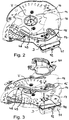
- Fig. 2
- eine schematische perspektivische Ansicht einer Ausführungsform eines der Dosierorgane der Verteilmaschine gemäß
Fig. 1 mit einem mit einer Auslauföffnung im Boden des Behälters zusammenwirkenden, schwenkbar gelagerten Dosierschieber von schräg unten betrachtet; - Fig. 3
- eine im Wesentlichen der
Fig. 2 entsprechende schematische perspektivische Ansicht des Dosierorgans in Explosionsdarstellung und einschließlich eines gleichfalls an der Unterseite des Bodens des Behälters festgelegten Auslaufschachtes; - Fig. 4
- eine schematische perspektivische Ansicht einer Ausführungsform eines erfindungsgemäßen Antriebs des Dosierschiebers des Dosierorgans gemäß
Fig. 2 und 3 , welcher eine entlang einer drehangetriebenen Gewindespindel geführte und hiermit im Eingriff stehende Spindelmutter umfasst, welche mit einem Hebelarm des Dosierschiebers in Verbindung steht, von schräg oben betrachtet; - Fig. 5
- den Antrieb des Dosierschiebers gemäß
Fig. 4 von schräg unten betrachtet; und - Fig. 6
- den Antrieb des Dosierschiebers gemäß
Fig. 4 und 5 ähnlich derFig. 4 von schräg oben betrachtet, aber zur Veranschaulichung der Anordnung des an dem Dosierschieber festgelegten Hebelarms mit entfernter Spindelmutter.
- Fig. 1
- a schematic perspective view of a distributor in the form of an agricultural two-disc spreader obliquely from the rear;
- Fig. 2
- a schematic perspective view of an embodiment of one of the metering members of the distributor according to FIG
Fig. 1 with a pivotably mounted metering slide cooperating with an outlet opening in the bottom of the container, viewed obliquely from below; - Fig. 3
- an essentially the
Fig. 2 corresponding schematic perspective view of the metering element in an exploded view and including an outlet shaft also fixed on the underside of the bottom of the container; - Fig. 4
- a schematic perspective view of an embodiment of a drive according to the invention of the metering slide of the metering member according to FIG
Figs. 2 and 3 which comprises a spindle nut guided along a rotationally driven threaded spindle and in engagement therewith, which is connected to a lever arm of the metering slide, viewed obliquely from above; - Fig. 5
- the drive of the metering slide according to
Fig. 4 viewed obliquely from below; and - Fig. 6
- the drive of the metering slide according to
Figures 4 and 5 similar to theFig. 4 Viewed obliquely from above, but to illustrate the arrangement of the lever arm attached to the metering slide with the spindle nut removed.
Die in der
Die Verteilmaschine weist ferner einen zur Bevorratung des Verteilgutes, wie insbesondere Dünger oder Saatgut, dienenden Behälter 7 auf, welcher im vorliegenden Fall zwei sich etwa trichterförmig nach unten verjüngende Behälterteile 8, 9 umfasst, welche am unteren Ende jeweils in ein Unterteil 10, 11 mit einem nach unten offenen Bodenring (in der
Darüber hinaus erkennt man in den
Wie wiederum aus der
Darüber hinaus kann einem jeweiligen Verteilorgan 3 in Form der Verteilerscheiben 4a, 4b eine nicht im Einzelnen zeichnerisch wiedergegebene Einrichtung zur Verstellung des Aufgabepunktes des Verteilgutes auf die Verteilerscheiben 4a, 4b zugeordnet sein, welche beispielsweise eine koaxial zur Drehachse V der Verteilerscheiben drehbare Lagerung der Böden 14 der Behälterteile 8, 9 des Behälters 7 und einen entsprechenden Drehantrieb - sei er manuell oder sei er insbesondere motorisch oder aktuatorisch - der Böden 14 umfasst, wie es als solches aus dem Stand der Technik, wie beispielsweise aus der eingangs zitierten
In den
Der von teleskopierbaren Teilen gänzlich freie Antrieb des Dosierschiebers 18 umfasst eine drehangetriebene, aber axialfest, z.B.an entsprechenden Lagerböcken 32a, 32b des Tragflansches 30 bzw. dessen Montageplatte 30b, drehbar gelagerte Gewindespindel 33, welche sich im Wesentlichen senkrecht zur Schwenkachse D des Dosierschiebers 18 und sowohl mit Abstand von als auch etwa tangential zu derselben erstreckt. Mit der Gewindespindel 33 steht eine lediglich in der
Wie den
Um die unterschiedlichen Abstände der Spindelmutter 34 bzw. des Nutensteins 35 in Bezug auf die Schwenkachse D des Dosierschiebers 18 je nach dem, in welcher Axialposition der Gewindespindel 33 sich die Spindelmutter 34 gerade befindet, zu kompensieren, weist der Hebelarm 39 an seinem dem die Schwenkachse D bildenden Wellenflansch 38 entgegengesetzten, der Spindelmutter 34 zugewandten Ende ein Langloch 40 auf, welches sich im Wesentlichen in Radialrichtung in Bezug auf die Schwenkachse D bzw. im Wesentlichen in Erstreckungsrichtung des Hebelarm 39 erstreckt. Der mit der Spindelmutter 34 verbundene Nutenstein 35 wiederum weist einen in das Langloch 40 des Hebelarms 39 eingreifenden und sich zweckmäßigerweise sowohl hierzu als auch zur Axialrichtung der Gewindespindel 33 etwa senkrecht erstreckenden Mitnehmer 41 auf (vgl. die
Wie sich des Weiteren aus den
Der elektromotorische Drehantrieb 43 weist zweckmäßigerweise einen in einem Gehäuse 47 aufgenommenen Elektromotor auf, wobei es sich bei dem Elektromotor insbesondere um einen Getriebemotor handeln kann, welcher mit einem Getriebe von praktisch beliebiger bekannter Bauart ausgestattet ist. Die Abtriebswelle 44 des elektromotorischen Drehantriebs 43 durchsetzt dabei das Gehäuse 47 an dessen Stirnseite und ist gegen letzteres mittels einer zeichnerisch nicht dargestellten Gleitringdichtung 40 staub- und flüssigkeitsdicht abgedichtet. In dem Gehäuse 47 des elektromotorischen Drehantriebs 43 können ferner vorzugsweise gleichfalls nicht zeichnerisch wiedergegebene Positionserfassungssensoren untergebracht sein, welcher beispielsweise nach Art von Winkel- und/oder Drehzahlsensoren die genaue Winkelstellung der Abtriebswelle 44 oder einer anderen Welle, z.B. des Getriebes, und folglich der hiermit korrespondierenden Position des Dosierschiebers 18 zu erfassen vermögen. Der oder die Positionserfassungssensor(en) steht bzw. stehen mit einer Steuer- und/oder Regeleinrichtung (ebenfalls nicht dargestellt) der Verteilmaschine in Wirkverbindung, um die gewünschten Dosiermengen bzw. Massenströme an Verteilgut einzustellen sowie insbesondere anhand des gleichfalls sensorisch erfassten Ist-Massenstromes an Verteilgut sowie gegebenenfalls auch in Abhängigkeit der, beispielsweise mittels GPS erfassten, Position der Verteilmaschine auf dem Feld während der Streuarbeit zu regeln. Der elektromotorische Drehantrieb 43 kann folglich nach Art eines Servomotors, wie beispielsweise eines bürstenlosen DC-Motors, ausgestaltet sein.The
Alternativ oder zusätzlich zu dem oder den Positionserfassungssensor(en) des elektromotorischen Drehantriebs 43 kann beispielsweise auch der der entlang der Gewindespindel 33 verlagerbaren Spindelmutter 34 bzw. dem hiermit drehfest verbundenen Nutenstein 35 ein Positionserfassungssensor (nicht gezeigt) zugeordnet sein, welcher zu den vorgenannten Zwecken gleichfalls mit der Steuer- und/oder Regeleinrichtung der Verteilmaschine in Verbindung steht und z.B. in Form eines an der sich parallel zu der Gewindespindel 33 erstreckenden Wandung 36 (vgl. die
Der elektromotorische Drehantrieb 43 kann ebenso wie die etwaigen Positionserfassungssensoren zweckmäßigerweise über eine an der Verteilmaschine oder an einer Zugmaschine derselben, wie z.B. einem Traktor, vorgesehene elektrische Schnittstelle (nicht gezeigt) an die Stromversorgung der Zugmaschine anschließbar sein, so dass die Verteilmaschine selbst keine eigene Stromversorgung erfordert, sondern vom Bordnetz der Zugmaschine mit elektrischer Energie versorgt wird.The
Schließlich erweist es sich als zweckmäßig, den gesamten Antrieb des Dosierschiebers 18 zum Schutz vor äußeren Einwirkungen zu verkapseln, was beispielsweise mittels einer auf den Tragflansch 30 - oder genauer: auf dessen Montageplatte 30b - aufsetzbaren Abdeckung 51 geschehen kann, deren der Schwenkachse D zugewandter Abschnitt in den
Claims (15)
- A distributing machine, in particular a spreading machine and/or sowing machine, having at least one container (7; 8, 9), supported by a support frame (1), for receiving powdered and/or particulate material to be distributed, at least one outlet opening (16) arranged on the base (14) of the container (7; 8, 9), a metering element that is arranged downstream of the outlet opening (16) and that has a motor-driven metering slide (18) that can be displaced relative to the outlet opening (16), and at least one distributing element (3), arranged downstream of the metering element, for distributing the material to be distributed on the ground, wherein the drive of the metering slide (18) of the metering element comprises a threaded spindle (33) that is mounted in an axially fixed manner and that is driven in rotation by means of a motor rotary drive (43) having an axially fixed output shaft (44), guided along which threaded spindle is a spindle nut (34) that is in engagement with the threaded spindle (33) and that is connected to the metering slide (18), or to a lever arm (39) arranged thereon, in order to actuate the metering slide (18) by rotation of the threaded spindle (33), characterized in that metering slide (18) of the metering element is rotationally displaceable about a pivot axis (D), which passes through the base (14) of the container (7; 8, 9) that is provided with the outlet opening (16), wherein, on the side of the base (14) that is opposite to the metering slide (18), a lever arm (39) that is connected in a rotationally fixed manner to its pivot axis (D) is connected to the spindle nut (34).
- The distributing machine as claimed in claim 1, characterized in that the threaded spindle (33) is driven in rotation by means of an electric-motor rotary drive (43), in particular in the form of a servomotor.
- The distributing machine as claimed in claim 1 or 2, characterized in that the threaded spindle (33)- is constituted by the output shaft (44) of the motor rotary drive (43) or is connected thereto in a rotationally fixed, in particular detachable, manner; or- is connected to the output shaft (44) of the motor rotary drive (43) by means of a belt drive (46), or by means of meshing toothed wheels.
- The distributing machine as claimed in any one of claims 1 to 3, characterized in that the output shaft (44) of the motor rotary drive (43) is arranged substantially parallel to the threaded spindle (33).
- The distributing machine as claimed in any one of claims 1 to 4, characterized in that the metering slide (18) of the metering element can be displaced rotationally- about the pivot axis (D) which is arranged substantially perpendicular in relation to the outlet opening (16); and/or- about the pivot axis (D) which is arranged substantially perpendicularly in relation to the axial direction of the threaded spindle (33); and/or- which is arranged at a radial distance from the threaded spindle (33).
- The distributing machine as claimed in any one of claims 1 to 5, characterized in that the spindle nut (34) is guided along the threaded spindle (33) by means of a sliding block (35), in which it is fastened in a rotationally fixed manner, wherein, in particular, the spindle nut (34) or the sliding block (35) has at least one driver (41), which extends substantially perpendicularly in relation to the axial direction of the threaded spindle (33), and which is in engagement with an oblong hole (40) of the metering slide (18) or of the lever (39) arm arranged thereon.
- The distributing machine as claimed in any one of claims 1 to 6, characterized in that the threaded spindle (33) is arranged, in particular jointly with its motor rotary drive (43), on the side of the outlet opening (16, 17) that is opposite to the metering slide (18) of the metering element.
- The distributing machine as claimed in any one of claims 1 to 7, characterized in that the threaded spindle (33) is arranged, in particular jointly with its motor rotary drive (43),- in particular detachably, on the base (14) of the container (7; 8, 9) that is provided with the outlet opening (16), or- on a support flange (30) fastened, in particular detachably, thereto.
- The distributing machine as claimed in any one of claims 1 to 8, characterized in that the metering slide (18) and/or the lever arm (39) connecting it to the spindle nut (34) is detachably connected to the pivot axis (D) of the metering slide (18).
- The distributing machine as claimed in any one of claims 1 to 9, characterized in that the lever arm (39) connecting the metering slide (18) of the metering element to the spindle nut (34) is displaceable between the base (14) of the container (7; 8, 9) that is provided with the outlet opening (16), or the support flange fastened thereto (30), and the motor rotary drive (43) of the threaded spindle (33), in particular substantially parallel to the plane of the base (14) or of the support flange (30).
- The distributing machine as claimed in any one of claims 1 to 10, characterized in that the motor rotary drive (43) is accommodated in a housing (47), wherein the housing (47), in particular,- is designed so as to be substantially dust-tight and liquid-tight, and/or- the axially fixed output shaft (44) of the motor rotary drive (43) is sealed against the housing (47), in particular by means of at least one mechanical face seal.
- The distributing machine as claimed in any one of claims 1 to 11, characterized in that the motor rotary drive (43) has at least one transmission, in particular in the form of a coupled transmission, coaxial transmission, bevel-gear transmission and/or planetarygear transmission.
- The distributing machine as claimed in any one of claims 1 to 12, characterized in that a position-sensing sensor, in particular in the form of an angular displacement sensor and/or a rotational-speed sensor, which is connected to an open-loop and/or closed-loop control means of the distributing machine, is assigned to the output shaft (44) of the motor rotary drive (43), or at least to another shaft of the motor rotary drive (43), or of a transmission thereof.
- The distributing machine as claimed in any one of claims 1 to 13, characterized in that, assigned to the spindle nut (34) that can be displaced along the threaded spindle (33), there is a position-sensing sensor, in particular in the form of a sliding contact or rubbing contact that is arranged on a wall (36) extending parallel to the threaded spindle (33) and that act.s in combination with the spindle nut (34), and that is connected to an open-loop and/or closed-loop control means of the distributing machine.
- The distributing machine as claimed in any one of claims 1 to 14, characterized in that fixed, in particular detachably, to the metering slide (18) there is a handle (48), such as substantially in the form of an operating lever (49) extending away therefrom, to enable the metering slide (18) to be actuated manually.
Applications Claiming Priority (2)
| Application Number | Priority Date | Filing Date | Title |
|---|---|---|---|
| DE202017001237.5U DE202017001237U1 (en) | 2017-03-09 | 2017-03-09 | Distributor and suitable metering device |
| PCT/EP2018/000085 WO2018162116A1 (en) | 2017-03-09 | 2018-03-05 | Distribution machine and metering element suitable for said distribution machine |
Publications (2)
| Publication Number | Publication Date |
|---|---|
| EP3592128A1 EP3592128A1 (en) | 2020-01-15 |
| EP3592128B1 true EP3592128B1 (en) | 2020-10-28 |
Family
ID=61691914
Family Applications (1)
| Application Number | Title | Priority Date | Filing Date |
|---|---|---|---|
| EP18712077.9A Active EP3592128B1 (en) | 2017-03-09 | 2018-03-05 | Distribution machine |
Country Status (7)
| Country | Link |
|---|---|
| US (1) | US11553642B2 (en) |
| EP (1) | EP3592128B1 (en) |
| AU (1) | AU2018230339B2 (en) |
| CA (1) | CA3052334C (en) |
| DE (1) | DE202017001237U1 (en) |
| DK (1) | DK3592128T3 (en) |
| WO (1) | WO2018162116A1 (en) |
Families Citing this family (5)
| Publication number | Priority date | Publication date | Assignee | Title |
|---|---|---|---|---|
| US10728752B2 (en) | 2015-10-13 | 2020-07-28 | Confivox Inc. | Case for a portable device |
| DE102016002827A1 (en) * | 2016-03-09 | 2017-09-14 | Rauch Landmaschinenfabrik Gmbh | distributing |
| CN110337879A (en) * | 2019-06-27 | 2019-10-18 | 凤台县馨水湾旅游开发有限公司 | Fertilizer apparatus is used in a kind of plantation of greenhouse wax gourd |
| CN114289738B (en) * | 2022-03-07 | 2022-05-24 | 四川工程职业技术学院 | Metal part additive forming system and method |
| IT202200008939A1 (en) | 2022-05-03 | 2023-11-03 | Dal Cero Metalworking Di Dal Cero Sergio & Diego S N C | AGRICULTURAL MACHINE FOR DISTRIBUTING TREATMENT PRODUCTS ON THE LAND AND METHOD OF OPERATION OF SAID MACHINE |
Family Cites Families (14)
| Publication number | Priority date | Publication date | Assignee | Title |
|---|---|---|---|---|
| US3191944A (en) | 1964-05-27 | 1965-06-29 | Guy A Watts | Remote controlled seed spreader |
| DE3617302A1 (en) * | 1986-05-23 | 1987-11-26 | Amazonen Werke Dreyer H | SPIN SPREADER WITH RESERVE |
| DE4012826A1 (en) | 1990-04-23 | 1991-10-24 | Amazonen Werke Dreyer H | DISTRIBUTION MACHINE |
| FR2669806B1 (en) | 1990-12-04 | 1993-03-19 | Sulky Burel Sa | METHOD AND DEVICE FOR MODIFYING THE SPECTRUM OF A CENTRIFUGAL SPREADING MACHINE FOR GRAIN PRODUCTS, WITH A VIEW TO SPREADING ON THE FIELD EDGE. |
| DE4105059C2 (en) | 1991-02-19 | 1999-07-01 | Amazonen Werke Dreyer H | Centrifugal fertilizer spreader |
| FR2719188B1 (en) | 1994-04-28 | 1996-09-20 | Sulky Burel | System for evaluating the grain density of a flow of suspended grains, machine and spreading method using such a system. |
| JP3504578B2 (en) | 2000-04-07 | 2004-03-08 | 産経物産株式会社 | Tile cutter |
| NL1014921C2 (en) | 2000-04-12 | 2001-10-15 | Kverneland Nieuw Vennep Bv | Device for spreading particulate fertilizer. |
| DE10126233A1 (en) * | 2001-05-30 | 2002-12-05 | Lehner Agrar Gmbh | Material distribution arrangement on vehicle e.g. for grits and agricultural fertilizers, includes metering device with adjustable aperture for varying width of output opening |
| DE102005015228B4 (en) | 2005-04-02 | 2015-05-21 | Rauch Landmaschinenfabrik Gmbh | Centrifugal spreader for spreading material |
| DE102007053550A1 (en) | 2007-11-07 | 2009-05-14 | Rauch Landmaschinenfabrik Gmbh | Zweischeibenstreuer |
| FR2967547B1 (en) | 2010-11-18 | 2014-02-07 | Sulky Burel | CENTRIFUGAL CHANNEL SPREADING DEVICE FOR TAKING INTO ACCOUNT THE FLOW EFFECT |
| DE202012010343U1 (en) | 2012-10-30 | 2014-02-04 | Rauch Landmaschinenfabrik Gmbh | distributing |
| DE102013104024A1 (en) | 2013-04-22 | 2014-11-06 | Amazonen-Werke H. Dreyer Gmbh & Co. Kg | hydraulic cylinders |
-
2017
- 2017-03-09 DE DE202017001237.5U patent/DE202017001237U1/en not_active Expired - Lifetime
-
2018
- 2018-03-05 EP EP18712077.9A patent/EP3592128B1/en active Active
- 2018-03-05 WO PCT/EP2018/000085 patent/WO2018162116A1/en unknown
- 2018-03-05 CA CA3052334A patent/CA3052334C/en active Active
- 2018-03-05 US US16/491,663 patent/US11553642B2/en active Active
- 2018-03-05 AU AU2018230339A patent/AU2018230339B2/en active Active
- 2018-03-05 DK DK18712077.9T patent/DK3592128T3/en active
Also Published As
| Publication number | Publication date |
|---|---|
| DK3592128T3 (en) | 2020-11-30 |
| CA3052334A1 (en) | 2018-09-13 |
| US11553642B2 (en) | 2023-01-17 |
| US20200000019A1 (en) | 2020-01-02 |
| BR112019016345A8 (en) | 2022-12-27 |
| EP3592128A1 (en) | 2020-01-15 |
| AU2018230339B2 (en) | 2023-05-04 |
| DE202017001237U1 (en) | 2018-03-12 |
| WO2018162116A1 (en) | 2018-09-13 |
| BR112019016345A2 (en) | 2020-04-07 |
| CA3052334C (en) | 2024-04-16 |
| AU2018230339A1 (en) | 2019-08-22 |
Similar Documents
| Publication | Publication Date | Title |
|---|---|---|
| EP3592128B1 (en) | Distribution machine | |
| DE102018006660A1 (en) | Dosing unit for powder or particulate material to be distributed and distribution machine with such a dosing unit | |
| EP0445842A1 (en) | Fertilizer broadcaster with hopper | |
| DE202013009703U1 (en) | Distributor with a container and its associated, pivoting cover | |
| DE102006056256A1 (en) | seeder | |
| DE102007038510A1 (en) | Device for dosing and distributing agricultural and municipal bulk materials | |
| EP2792228B1 (en) | Spreader device | |
| DE19513423A1 (en) | Centrifugal fertilizer spreader | |
| EP3426014B1 (en) | Distribution machine | |
| DE102018001875A1 (en) | Double disc spreader with hydraulic drive of the distributor discs | |
| EP2386198B1 (en) | Fertilizer spreader | |
| EP0496285A1 (en) | Centrifugal spreader | |
| EP3011818B1 (en) | Spreader machine with a hopper equipped with a stirrer | |
| DE3616538C2 (en) | ||
| DE102016204433A1 (en) | Row unit of an agricultural machine | |
| EP2301316B1 (en) | Two-disk caster with variable distribution pattern | |
| EP1695609B1 (en) | Lawn mower | |
| DE102012100930A1 (en) | Centrifugal fertilizer spreader for use in agricultural tractor, has positioning device and shaft including sensor that measures rotational torque, where torque and/or force are produced by fertilizer mass flow to be thrown off from shovel | |
| DE102017000022A1 (en) | disc spreader | |
| DE1757513C (en) | Device for throwing out manure containing manure | |
| DE202019003491U1 (en) | Double disc spreader | |
| DE102010036791A1 (en) | Centrifugal spreader for use with tractor, has centrifugal force shift member releasing switching impulse for adjusting throw shovels and/or inner part and/or outer part of shovels, during reaching and/or lowering speed range | |
| BR112019016345B1 (en) | DISTRIBUTION MACHINE AND APPROPRIATE DOSING BODY FOR THIS | |
| EP1269817A2 (en) | Method and centrifugal distributer for distribution of scattering material | |
| DE19756722A1 (en) | Centrifugal scatterer |
Legal Events
| Date | Code | Title | Description |
|---|---|---|---|
| STAA | Information on the status of an ep patent application or granted ep patent |
Free format text: STATUS: UNKNOWN |
|
| STAA | Information on the status of an ep patent application or granted ep patent |
Free format text: STATUS: THE INTERNATIONAL PUBLICATION HAS BEEN MADE |
|
| PUAI | Public reference made under article 153(3) epc to a published international application that has entered the european phase |
Free format text: ORIGINAL CODE: 0009012 |
|
| STAA | Information on the status of an ep patent application or granted ep patent |
Free format text: STATUS: REQUEST FOR EXAMINATION WAS MADE |
|
| 17P | Request for examination filed |
Effective date: 20190819 |
|
| AK | Designated contracting states |
Kind code of ref document: A1 Designated state(s): AL AT BE BG CH CY CZ DE DK EE ES FI FR GB GR HR HU IE IS IT LI LT LU LV MC MK MT NL NO PL PT RO RS SE SI SK SM TR |
|
| AX | Request for extension of the european patent |
Extension state: BA ME |
|
| DAV | Request for validation of the european patent (deleted) | ||
| DAX | Request for extension of the european patent (deleted) | ||
| GRAP | Despatch of communication of intention to grant a patent |
Free format text: ORIGINAL CODE: EPIDOSNIGR1 |
|
| STAA | Information on the status of an ep patent application or granted ep patent |
Free format text: STATUS: GRANT OF PATENT IS INTENDED |
|
| INTG | Intention to grant announced |
Effective date: 20200803 |
|
| GRAS | Grant fee paid |
Free format text: ORIGINAL CODE: EPIDOSNIGR3 |
|
| GRAA | (expected) grant |
Free format text: ORIGINAL CODE: 0009210 |
|
| STAA | Information on the status of an ep patent application or granted ep patent |
Free format text: STATUS: THE PATENT HAS BEEN GRANTED |
|
| AK | Designated contracting states |
Kind code of ref document: B1 Designated state(s): AL AT BE BG CH CY CZ DE DK EE ES FI FR GB GR HR HU IE IS IT LI LT LU LV MC MK MT NL NO PL PT RO RS SE SI SK SM TR |
|
| REG | Reference to a national code |
Ref country code: GB Ref legal event code: FG4D Free format text: NOT ENGLISH |
|
| REG | Reference to a national code |
Ref country code: CH Ref legal event code: EP |
|
| REG | Reference to a national code |
Ref country code: AT Ref legal event code: REF Ref document number: 1327241 Country of ref document: AT Kind code of ref document: T Effective date: 20201115 |
|
| REG | Reference to a national code |
Ref country code: DE Ref legal event code: R096 Ref document number: 502018002859 Country of ref document: DE |
|
| REG | Reference to a national code |
Ref country code: IE Ref legal event code: FG4D Free format text: LANGUAGE OF EP DOCUMENT: GERMAN |
|
| REG | Reference to a national code |
Ref country code: DK Ref legal event code: T3 Effective date: 20201126 |
|
| REG | Reference to a national code |
Ref country code: NL Ref legal event code: FP |
|
| PG25 | Lapsed in a contracting state [announced via postgrant information from national office to epo] |
Ref country code: GR Free format text: LAPSE BECAUSE OF FAILURE TO SUBMIT A TRANSLATION OF THE DESCRIPTION OR TO PAY THE FEE WITHIN THE PRESCRIBED TIME-LIMIT Effective date: 20210129 Ref country code: NO Free format text: LAPSE BECAUSE OF FAILURE TO SUBMIT A TRANSLATION OF THE DESCRIPTION OR TO PAY THE FEE WITHIN THE PRESCRIBED TIME-LIMIT Effective date: 20210128 Ref country code: PT Free format text: LAPSE BECAUSE OF FAILURE TO SUBMIT A TRANSLATION OF THE DESCRIPTION OR TO PAY THE FEE WITHIN THE PRESCRIBED TIME-LIMIT Effective date: 20210301 Ref country code: RS Free format text: LAPSE BECAUSE OF FAILURE TO SUBMIT A TRANSLATION OF THE DESCRIPTION OR TO PAY THE FEE WITHIN THE PRESCRIBED TIME-LIMIT Effective date: 20201028 Ref country code: FI Free format text: LAPSE BECAUSE OF FAILURE TO SUBMIT A TRANSLATION OF THE DESCRIPTION OR TO PAY THE FEE WITHIN THE PRESCRIBED TIME-LIMIT Effective date: 20201028 |
|
| REG | Reference to a national code |
Ref country code: LT Ref legal event code: MG4D |
|
| PG25 | Lapsed in a contracting state [announced via postgrant information from national office to epo] |
Ref country code: SE Free format text: LAPSE BECAUSE OF FAILURE TO SUBMIT A TRANSLATION OF THE DESCRIPTION OR TO PAY THE FEE WITHIN THE PRESCRIBED TIME-LIMIT Effective date: 20201028 Ref country code: PL Free format text: LAPSE BECAUSE OF FAILURE TO SUBMIT A TRANSLATION OF THE DESCRIPTION OR TO PAY THE FEE WITHIN THE PRESCRIBED TIME-LIMIT Effective date: 20201028 Ref country code: IS Free format text: LAPSE BECAUSE OF FAILURE TO SUBMIT A TRANSLATION OF THE DESCRIPTION OR TO PAY THE FEE WITHIN THE PRESCRIBED TIME-LIMIT Effective date: 20210228 Ref country code: LV Free format text: LAPSE BECAUSE OF FAILURE TO SUBMIT A TRANSLATION OF THE DESCRIPTION OR TO PAY THE FEE WITHIN THE PRESCRIBED TIME-LIMIT Effective date: 20201028 Ref country code: BG Free format text: LAPSE BECAUSE OF FAILURE TO SUBMIT A TRANSLATION OF THE DESCRIPTION OR TO PAY THE FEE WITHIN THE PRESCRIBED TIME-LIMIT Effective date: 20210128 Ref country code: ES Free format text: LAPSE BECAUSE OF FAILURE TO SUBMIT A TRANSLATION OF THE DESCRIPTION OR TO PAY THE FEE WITHIN THE PRESCRIBED TIME-LIMIT Effective date: 20201028 |
|
| PG25 | Lapsed in a contracting state [announced via postgrant information from national office to epo] |
Ref country code: HR Free format text: LAPSE BECAUSE OF FAILURE TO SUBMIT A TRANSLATION OF THE DESCRIPTION OR TO PAY THE FEE WITHIN THE PRESCRIBED TIME-LIMIT Effective date: 20201028 |
|
| REG | Reference to a national code |
Ref country code: DE Ref legal event code: R097 Ref document number: 502018002859 Country of ref document: DE |
|
| PG25 | Lapsed in a contracting state [announced via postgrant information from national office to epo] |
Ref country code: SM Free format text: LAPSE BECAUSE OF FAILURE TO SUBMIT A TRANSLATION OF THE DESCRIPTION OR TO PAY THE FEE WITHIN THE PRESCRIBED TIME-LIMIT Effective date: 20201028 Ref country code: SK Free format text: LAPSE BECAUSE OF FAILURE TO SUBMIT A TRANSLATION OF THE DESCRIPTION OR TO PAY THE FEE WITHIN THE PRESCRIBED TIME-LIMIT Effective date: 20201028 Ref country code: EE Free format text: LAPSE BECAUSE OF FAILURE TO SUBMIT A TRANSLATION OF THE DESCRIPTION OR TO PAY THE FEE WITHIN THE PRESCRIBED TIME-LIMIT Effective date: 20201028 Ref country code: CZ Free format text: LAPSE BECAUSE OF FAILURE TO SUBMIT A TRANSLATION OF THE DESCRIPTION OR TO PAY THE FEE WITHIN THE PRESCRIBED TIME-LIMIT Effective date: 20201028 Ref country code: LT Free format text: LAPSE BECAUSE OF FAILURE TO SUBMIT A TRANSLATION OF THE DESCRIPTION OR TO PAY THE FEE WITHIN THE PRESCRIBED TIME-LIMIT Effective date: 20201028 Ref country code: RO Free format text: LAPSE BECAUSE OF FAILURE TO SUBMIT A TRANSLATION OF THE DESCRIPTION OR TO PAY THE FEE WITHIN THE PRESCRIBED TIME-LIMIT Effective date: 20201028 |
|
| PLBE | No opposition filed within time limit |
Free format text: ORIGINAL CODE: 0009261 |
|
| STAA | Information on the status of an ep patent application or granted ep patent |
Free format text: STATUS: NO OPPOSITION FILED WITHIN TIME LIMIT |
|
| 26N | No opposition filed |
Effective date: 20210729 |
|
| PG25 | Lapsed in a contracting state [announced via postgrant information from national office to epo] |
Ref country code: AL Free format text: LAPSE BECAUSE OF FAILURE TO SUBMIT A TRANSLATION OF THE DESCRIPTION OR TO PAY THE FEE WITHIN THE PRESCRIBED TIME-LIMIT Effective date: 20201028 Ref country code: MC Free format text: LAPSE BECAUSE OF FAILURE TO SUBMIT A TRANSLATION OF THE DESCRIPTION OR TO PAY THE FEE WITHIN THE PRESCRIBED TIME-LIMIT Effective date: 20201028 |
|
| REG | Reference to a national code |
Ref country code: CH Ref legal event code: PL |
|
| PG25 | Lapsed in a contracting state [announced via postgrant information from national office to epo] |
Ref country code: SI Free format text: LAPSE BECAUSE OF FAILURE TO SUBMIT A TRANSLATION OF THE DESCRIPTION OR TO PAY THE FEE WITHIN THE PRESCRIBED TIME-LIMIT Effective date: 20201028 |
|
| REG | Reference to a national code |
Ref country code: BE Ref legal event code: MM Effective date: 20210331 |
|
| PG25 | Lapsed in a contracting state [announced via postgrant information from national office to epo] |
Ref country code: LI Free format text: LAPSE BECAUSE OF NON-PAYMENT OF DUE FEES Effective date: 20210331 Ref country code: IE Free format text: LAPSE BECAUSE OF NON-PAYMENT OF DUE FEES Effective date: 20210305 Ref country code: LU Free format text: LAPSE BECAUSE OF NON-PAYMENT OF DUE FEES Effective date: 20210305 Ref country code: CH Free format text: LAPSE BECAUSE OF NON-PAYMENT OF DUE FEES Effective date: 20210331 |
|
| PG25 | Lapsed in a contracting state [announced via postgrant information from national office to epo] |
Ref country code: IS Free format text: LAPSE BECAUSE OF FAILURE TO SUBMIT A TRANSLATION OF THE DESCRIPTION OR TO PAY THE FEE WITHIN THE PRESCRIBED TIME-LIMIT Effective date: 20210228 |
|
| PG25 | Lapsed in a contracting state [announced via postgrant information from national office to epo] |
Ref country code: BE Free format text: LAPSE BECAUSE OF NON-PAYMENT OF DUE FEES Effective date: 20210331 |
|
| GBPC | Gb: european patent ceased through non-payment of renewal fee |
Effective date: 20220305 |
|
| PG25 | Lapsed in a contracting state [announced via postgrant information from national office to epo] |
Ref country code: GB Free format text: LAPSE BECAUSE OF NON-PAYMENT OF DUE FEES Effective date: 20220305 |
|
| PGFP | Annual fee paid to national office [announced via postgrant information from national office to epo] |
Ref country code: FR Payment date: 20230329 Year of fee payment: 6 Ref country code: DK Payment date: 20230323 Year of fee payment: 6 |
|
| P01 | Opt-out of the competence of the unified patent court (upc) registered |
Effective date: 20230425 |
|
| PG25 | Lapsed in a contracting state [announced via postgrant information from national office to epo] |
Ref country code: CY Free format text: LAPSE BECAUSE OF FAILURE TO SUBMIT A TRANSLATION OF THE DESCRIPTION OR TO PAY THE FEE WITHIN THE PRESCRIBED TIME-LIMIT Effective date: 20201028 |
|
| PG25 | Lapsed in a contracting state [announced via postgrant information from national office to epo] |
Ref country code: HU Free format text: LAPSE BECAUSE OF FAILURE TO SUBMIT A TRANSLATION OF THE DESCRIPTION OR TO PAY THE FEE WITHIN THE PRESCRIBED TIME-LIMIT; INVALID AB INITIO Effective date: 20180305 |
|
| PGFP | Annual fee paid to national office [announced via postgrant information from national office to epo] |
Ref country code: IT Payment date: 20230331 Year of fee payment: 6 |
|
| REG | Reference to a national code |
Ref country code: DE Ref legal event code: R081 Ref document number: 502018002859 Country of ref document: DE Owner name: RAUCH LANDMASCHINENFABRIK GESELLSCHAFT MIT BES, DE Free format text: FORMER OWNER: RAUCH LANDMASCHINENFABRIK GMBH, 76547 SINZHEIM, DE |
|
| PGFP | Annual fee paid to national office [announced via postgrant information from national office to epo] |
Ref country code: NL Payment date: 20240320 Year of fee payment: 7 |
|
| PG25 | Lapsed in a contracting state [announced via postgrant information from national office to epo] |
Ref country code: MK Free format text: LAPSE BECAUSE OF FAILURE TO SUBMIT A TRANSLATION OF THE DESCRIPTION OR TO PAY THE FEE WITHIN THE PRESCRIBED TIME-LIMIT Effective date: 20201028 |
|
| PGFP | Annual fee paid to national office [announced via postgrant information from national office to epo] |
Ref country code: DE Payment date: 20240315 Year of fee payment: 7 |