EP3592041B1 - Method and apparatus for transmitting system information - Google Patents
Method and apparatus for transmitting system information Download PDFInfo
- Publication number
- EP3592041B1 EP3592041B1 EP17901594.6A EP17901594A EP3592041B1 EP 3592041 B1 EP3592041 B1 EP 3592041B1 EP 17901594 A EP17901594 A EP 17901594A EP 3592041 B1 EP3592041 B1 EP 3592041B1
- Authority
- EP
- European Patent Office
- Prior art keywords
- terminal device
- system information
- base station
- application
- duration
- Prior art date
- Legal status (The legal status is an assumption and is not a legal conclusion. Google has not performed a legal analysis and makes no representation as to the accuracy of the status listed.)
- Active
Links
- 238000000034 method Methods 0.000 title claims description 67
- 230000005540 biological transmission Effects 0.000 claims description 44
- 238000012545 processing Methods 0.000 description 37
- 238000004891 communication Methods 0.000 description 36
- 230000015654 memory Effects 0.000 description 31
- 238000010586 diagram Methods 0.000 description 24
- 230000001413 cellular effect Effects 0.000 description 21
- 230000006870 function Effects 0.000 description 19
- 230000008569 process Effects 0.000 description 11
- 230000011664 signaling Effects 0.000 description 8
- 230000004048 modification Effects 0.000 description 7
- 238000012986 modification Methods 0.000 description 7
- 238000004590 computer program Methods 0.000 description 6
- 101150096310 SIB1 gene Proteins 0.000 description 5
- 238000005516 engineering process Methods 0.000 description 4
- 230000008859 change Effects 0.000 description 3
- 238000013461 design Methods 0.000 description 2
- 230000007774 longterm Effects 0.000 description 2
- 230000004622 sleep time Effects 0.000 description 2
- 239000002699 waste material Substances 0.000 description 2
- 230000010267 cellular communication Effects 0.000 description 1
- 230000003993 interaction Effects 0.000 description 1
- 230000003287 optical effect Effects 0.000 description 1
- CSRZQMIRAZTJOY-UHFFFAOYSA-N trimethylsilyl iodide Substances C[Si](C)(C)I CSRZQMIRAZTJOY-UHFFFAOYSA-N 0.000 description 1
Images


Classifications
-
- H—ELECTRICITY
- H04—ELECTRIC COMMUNICATION TECHNIQUE
- H04W—WIRELESS COMMUNICATION NETWORKS
- H04W68/00—User notification, e.g. alerting and paging, for incoming communication, change of service or the like
- H04W68/005—Transmission of information for alerting of incoming communication
-
- H—ELECTRICITY
- H04—ELECTRIC COMMUNICATION TECHNIQUE
- H04W—WIRELESS COMMUNICATION NETWORKS
- H04W48/00—Access restriction; Network selection; Access point selection
- H04W48/08—Access restriction or access information delivery, e.g. discovery data delivery
- H04W48/12—Access restriction or access information delivery, e.g. discovery data delivery using downlink control channel
-
- H—ELECTRICITY
- H04—ELECTRIC COMMUNICATION TECHNIQUE
- H04W—WIRELESS COMMUNICATION NETWORKS
- H04W4/00—Services specially adapted for wireless communication networks; Facilities therefor
- H04W4/06—Selective distribution of broadcast services, e.g. multimedia broadcast multicast service [MBMS]; Services to user groups; One-way selective calling services
-
- H—ELECTRICITY
- H04—ELECTRIC COMMUNICATION TECHNIQUE
- H04W—WIRELESS COMMUNICATION NETWORKS
- H04W72/00—Local resource management
- H04W72/20—Control channels or signalling for resource management
-
- H—ELECTRICITY
- H04—ELECTRIC COMMUNICATION TECHNIQUE
- H04W—WIRELESS COMMUNICATION NETWORKS
- H04W76/00—Connection management
- H04W76/20—Manipulation of established connections
- H04W76/27—Transitions between radio resource control [RRC] states
-
- H—ELECTRICITY
- H04—ELECTRIC COMMUNICATION TECHNIQUE
- H04W—WIRELESS COMMUNICATION NETWORKS
- H04W8/00—Network data management
- H04W8/005—Discovery of network devices, e.g. terminals
-
- H—ELECTRICITY
- H04—ELECTRIC COMMUNICATION TECHNIQUE
- H04W—WIRELESS COMMUNICATION NETWORKS
- H04W92/00—Interfaces specially adapted for wireless communication networks
- H04W92/16—Interfaces between hierarchically similar devices
- H04W92/18—Interfaces between hierarchically similar devices between terminal devices
-
- Y—GENERAL TAGGING OF NEW TECHNOLOGICAL DEVELOPMENTS; GENERAL TAGGING OF CROSS-SECTIONAL TECHNOLOGIES SPANNING OVER SEVERAL SECTIONS OF THE IPC; TECHNICAL SUBJECTS COVERED BY FORMER USPC CROSS-REFERENCE ART COLLECTIONS [XRACs] AND DIGESTS
- Y02—TECHNOLOGIES OR APPLICATIONS FOR MITIGATION OR ADAPTATION AGAINST CLIMATE CHANGE
- Y02D—CLIMATE CHANGE MITIGATION TECHNOLOGIES IN INFORMATION AND COMMUNICATION TECHNOLOGIES [ICT], I.E. INFORMATION AND COMMUNICATION TECHNOLOGIES AIMING AT THE REDUCTION OF THEIR OWN ENERGY USE
- Y02D30/00—Reducing energy consumption in communication networks
- Y02D30/70—Reducing energy consumption in communication networks in wireless communication networks
Definitions
- This application relates to the field of communications technologies, and in particular, to system information transmission and reception methods.
- Document US 2016/0007271 A1 discloses methods and devices for providing system information of a cellular communication network.
- Document WO 2011/099744 A2 discloses a method and an apparatus of transmitting and receiving system information in a wireless communication system.
- Document WO 2011/100707 A1 discloses techniques for reading and caching of system information to reduce a call setup delay.
- a device-to-device (Device-to-Device, D2D) communication mode is a communication mode in which a transmit end directly sends data to a receive end without forwarding by a base station or a cellular network.
- a relatively special mode in the D2D communication mode is a UE-to-network relay scenario.
- a terminal device for example, user equipment (User Equipment, UE)
- UE user equipment
- UE user equipment
- Relay UE relay terminal device
- a base station of the camped-on cell or the serving cell of the remote terminal device sends a paging message to the remote terminal device, and indicates, by using the paging message, that the system information changes.
- the remote terminal device determines that the system information changes and obtains changed system information.
- the remote terminal device needs to be located in coverage of a cell to obtain the changed system information, and receives the changed system information through a cellular link between the remote terminal device and the base station.
- the remote terminal device receives the system information in the foregoing manner, resulting in relatively high complexity and relatively high power consumption.
- Embodiments of this application provide a system information transmission method and a system information reception method, to reduce complexity and power consumption of receiving system information by a remote terminal device.
- a system information reception method comprises, determining, by a first terminal device, on duration of the first terminal device, receiving, by the first terminal device during the on duration of the first terminal device, first system information sent by a second terminal device, wherein the first system information is a part or all of second system information delivered by a base station.
- the method is further characterized in that before the receiving, by the first terminal device, first system information sent by a second terminal device, the method further comprises, receiving, by the first terminal device, indication information sent by the second terminal device, wherein the indication information indicates that the first system information has changed, wherein the on duration of the first terminal device is a paging occasion of the first terminal device, wherein the receiving, by the first terminal device during the on duration of the first terminal device, first system information sent by a second terminal device comprises, receiving, by the first terminal device during the on duration of the first terminal device, the first system information, wherein the first system information is sent by the second terminal device at least one time by using a resource in a sending resource pool, wherein the sending resource pool is configured by the base station by using a broadcast message.
- a system information transmission method comprises determining, by a second terminal device, on duration of a first terminal device, and sending, by the second terminal device, first system information to the first terminal device during the on duration of the first terminal device, wherein the first system information is a part or all of second system information delivered by a base station.
- the method is characterized in that before the sending, by the second terminal device, first system information to the first terminal device, the method further comprises, sending, by the second terminal device, indication information to the first terminal device, wherein the indication information indicates that the first system information has changed, wherein the on duration of the first terminal device is a paging occasion of the first terminal device, wherein the sending (S102), by the second terminal device, first system information to the first terminal device during the on duration of the first terminal device comprises, sending, by the second terminal device, the first system information at least one time during the on duration of the first terminal device by using a resource in a sending resource pool, wherein the sending resource pool is configured by the base station by using a broadcast message.
- a system information transmission method provided in the embodiments of this application may be applied to a communication scenario in which two devices directly communicate with each other.
- devices that directly communicate with each other may include various handheld devices, in-vehicle devices, wearable devices, or computing devices with a wireless communication function, or other processing devices connected to a wireless modem, and user equipment (User Equipment, UE) in various forms, mobile stations (Mobile station, MS) in various forms, terminals (terminal) in various forms, terminal devices (Terminal Equipment) in various forms, and the like.
- user equipment User Equipment
- MS mobile stations
- terminals terminal
- terminal devices Terminal Equipment
- a UE-to-network relay scenario is a typical application scenario in which two devices directly communicate with each other.
- FIG. 1 is a schematic architectural diagram of the UE-to-network relay scenario.
- a link between a network device and a first terminal device and a link between the network device and a second terminal device may be referred to as cellular links or may be referred to as an uplink and a downlink, and a link between the first terminal device and the second terminal device may be referred to as a sidelink.
- the second terminal device is a terminal device that directly interacts with the network device and may also be referred to as a relay terminal device
- the first terminal device is a terminal device that communicates with the network device by using the second terminal device and may also be referred to as a remote terminal device.
- control signaling of the first terminal device may interact with the network device through a cellular link
- user data of the first terminal device may interact with the network device through a sidelink. That is, user data between the first terminal device and the network device may be forwarded to the first terminal device by using the second terminal device, or user data between the second terminal device and the network device may be forwarded to the network device by using the first terminal device.
- both control signaling and user data of the second terminal device may interact with the network device through a sidelink.
- the network device in FIG. 1 is an apparatus that is deployed in a radio access network and provides a wireless communication function for a terminal, and may be a base station (base station, BS), for example, may include various forms such as a macro base station, a micro base station, a relay station, and an access point.
- a name of a device with a base station function may vary.
- the device is referred to as an evolved NodeB (evolved NodeB, eNB or eNodeB for short) in a long term evolution (Long Term Evolution, LTE) network, or is referred to as a NodeB (NodeB) in a third generation 3G network.
- the network device that communicates with the first terminal device and the second terminal device is referred to as a base station below.
- the serving cell is a cell to which a terminal device is connected when the terminal device is in a radio resource control (Radio Resource Control, RRC) connected mode.
- the camped-on cell is a cell on which a terminal device camps when the terminal device is in an RRC idle mode.
- the system information is a message that is periodically broadcast by the base station to all terminal devices in a cell on a broadcast channel.
- the system information is classified into a master information block (Master Information Block, MIB) and a plurality of system information blocks (System Information Blocks, SIB).
- the master information block includes a limited quantity of most important and commonly used transmission parameters for reading other cell information.
- the system information block includes other required parameters, including 20 system information blocks: a SIB1 to a SIB20.
- the first terminal device may camp on the second terminal device connected to the first terminal device.
- the first terminal device may obtain the system information through a cellular link or may obtain the system information by using the second terminal device.
- the first terminal device when cell system information has changed, receives, during on duration of the first terminal device, system information sent by the second terminal device, so that the first terminal device can receive the system information through a sidelink between the first terminal device and the second terminal device without a need to maintain a cellular link, thereby reducing complexity and power consumption of system information transmission.
- the first terminal device may obtain system information within a gap period between the second terminal device and the first terminal device through a link between the first terminal device and the base station. Communication between the second terminal device and the first terminal device is suspended within the gap period, so that the changed system information can be received through a cellular link.
- the first terminal device may maintain the cellular link only within the gap period, and does not need to maintain the cellular link within a period other than the gap period, thereby reducing complexity and power consumption of system information transmission to some extent.
- system information transmission method is not limited to the application scenario shown in FIG. 1 , and may also be applied to an application scenario in which two other devices directly communicate with each other, for example, a short-range communication scenario in which a Bluetooth technology or a wireless fidelity (Wireless Fidelity, WiFi) technology is used.
- a short-range communication scenario in which a Bluetooth technology or a wireless fidelity (Wireless Fidelity, WiFi) technology is used.
- the following describes a specific implementation method in which the first terminal device receives the system information by using the second terminal device or the cellular link with reference to actual application in the embodiments of this application.
- FIG. 2 is an implementation flowchart of a system information transmission method according to an embodiment of this application. Referring to FIG. 2 , the method includes the following steps.
- a second terminal device determines on duration of a first terminal device.
- the on duration of the first terminal device is a time in which the first terminal device may send and receive a message.
- the on duration is a paging occasion (Paging Occasion, PO) of the first terminal device in an RRC idle mode, or may be a time in which the first terminal device receives a discovery message sent by the second terminal device, or may be a time in which the first terminal device in an RRC connected mode receives a message sent by the second terminal device, including a time in which the first terminal device that is in an RRC connected mode and is configured with discontinuous reception (Discontinuous Reception: DRX) is in DRX on duration (on duration), or may be another time in which the first terminal device may receive a message sent by the second terminal device. That the second terminal device determines the on duration of the first terminal device may be understood as that the second terminal device calculates the on duration of the first terminal device, or the second terminal device obtains a configuration of the on duration of the first terminal device.
- Paging Occasion, PO paging occasion
- the second terminal device sends system information to the first terminal device during the on duration of the first terminal device.
- the first terminal device receives, during the on duration of the first terminal device, the system information sent by the second terminal device.
- a part of system information delivered by a base station of a camped-on cell or a serving cell of the second terminal device is required by all first terminal devices that complete establishment of a direct link to the second terminal device.
- this part of system information may be referred to as basic system information, for example, cell access related information IE cellAccessRelatedInfo in a SIB1.
- Another part of system information delivered by the base station of the camped-on cell or the serving cell of the second terminal device has different requirements for first terminal devices of different types, capabilities, and service requirements.
- this part of system information may be referred to as specific system information.
- system information required by a first terminal device that supports extended access control is a SIB14
- system information required by a first terminal device that supports a multimedia broadcast multicast service is a SIB13, a SIB15, and the like
- system information required by a first terminal device that supports collaboration between a universal mobile telecommunications system (Universal Mobile Telecommunication System, UMTS) evolved universal terrestrial radio access network (Evolved Universal Terrestrial Radio Access Network, E-UTRAN) and a wireless local area network (Wireless Local Area Networks, WLAN) is a SIB17 and the like.
- a first terminal device may not require specific system information, and specific system information required by different first terminal devices may be the same or partially the same.
- System information that needs to be obtained by a first terminal device includes basic system information and specific system information required by the first terminal device, and the first terminal device does not need to obtain specific system information of another first terminal device.
- the second terminal device may send, to the first terminal device, system information required by the first terminal device, where the system information required by the first terminal device may be a part or all of system information delivered by the base station of the camped-on cell or the serving cell of the second terminal device.
- the second terminal device may store specific system information required by the first terminal device.
- the system information required by the first terminal device may be changed system information in the system information required by the first terminal device or all system information required by the first terminal device.
- the second terminal device may send the system information by using a broadcast address, in other words, send the system information to the first terminal device in a broadcast manner, so that all first terminal devices connected to the second terminal device can receive the system information.
- the second terminal device may alternatively send the system information to the first terminal device by using a multicast address, in other words, send the system information to the first terminal device in a multicast manner, so that some first terminal devices connected to the second terminal device can receive the system information.
- the second terminal device may alternatively send the system information to the first terminal device by using a unicast address, in other words, send the system information to the first terminal device in a unicast manner, so that a first terminal device connected to the second terminal device can receive the system information sent by the second terminal device.
- the first terminal device when cell system information has changed, receives, during the on duration of the first terminal device, the system information sent by the second terminal device, so that the first terminal device can receive the system information through a sidelink between the first terminal device and the second terminal device without a need to maintain a cellular link, thereby reducing complexity and power consumption of system information transmission.
- the embodiments of this application describe below an implementation process of transmitting system information between the second terminal device and the first terminal device in various scenarios in which the on duration of the first terminal is the paging occasion of the first terminal device, the on duration of the first terminal is a time in which the second terminal device sends the discovery message, and the on duration of the first terminal is a time in which the first terminal device is in an RRC connected mode and may receive the message sent by the second terminal device.
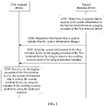
- FIG. 3 is an implementation flowchart of a method for transmitting system information by a first terminal device and a second terminal device on a paging occasion according to an embodiment of this application. As shown in FIG. 3 , the method includes the following steps.
- a second terminal device determines a resource that is used to send system information to a first terminal device on a paging occasion of the first terminal device.
- the second terminal device may send the system information to the first terminal device by using a dedicated resource.
- the dedicated resource is determined by a base station based on a dedicated resource requested by the second terminal device from the base station and a time domain location that is of the paging occasion and that is indicated by the second terminal device to the base station.
- the second terminal device may request the dedicated resource from the base station, and indicate the time domain location of the paging occasion, and the second terminal device indicates the time domain location of the paging occasion to the base station, so that the base station allocates the dedicated resource to the paging occasion corresponding to the time domain location.
- the second terminal device indicates the time domain location of the paging occasion to the base station may be: the second terminal device may indicate, to the base station, an S-temporary mobile subscriber identity (S-Temporary Mobile Subscriber Identity, s-TMSI), a user equipment-specific discontinuous reception cycle (UE-specific DRX cycle), or a specific subframe index such as 0, 4, 5, or 9, and other information that may be used to determine the time domain location of the paging occasion, and the base station may determine the time domain location of the paging occasion by using the indicated information.
- S-temporary mobile subscriber identity S-Temporary Mobile Subscriber Identity, s-TMSI
- UE-specific DRX cycle user equipment-specific discontinuous reception cycle
- a specific subframe index such as 0, 4, 5, or 9
- the second terminal device uses a resource in a sending resource pool that is configured or preconfigured by a base station by using a broadcast message as a resource that is used by the second terminal device to send the system information to the first terminal device.
- a time domain location of the resource that is in the sending resource pool and that is used by the second terminal device overlaps with a time domain location of the paging occasion of the first terminal device, so that when the second terminal device sends the system information by using the resource in the sending resource pool, the first terminal device can receive the system information sent by the second terminal device.
- the resource in the sending resource pool may be a resource that is used by the second terminal device to send a paging message.
- the second terminal device may directly send the system information by using a resource that is used by a paging message originally sent by the second terminal device, and use the sending resource used by the original paging message as the resource in the sending resource pool.
- the second terminal device may alternatively add the system information to the original paging message to obtain a new paging message, and use a sending resource used by the new paging message as the resource in the sending resource pool.
- the resource in the sending resource pool may be alternatively a resource that is specially used by the second terminal device to send the system information to the first terminal device.
- the base station may schedule a resource in the resource pool to another terminal device for use when the second terminal device does not use the resource (when the system information does not change), thereby reducing resource waste.
- the second terminal device when the base station configures the sending resource pool for the second terminal device, the second terminal device may be in an RRC connected mode or an RRC idle mode. Regardless of whether the second terminal device is in an RRC connected mode or an RRC idle mode, the second terminal device can select, from the sending resource pool, a resource used for sending the system information.
- the second terminal device sends the system information to the first terminal device on the paging occasion of the first terminal device by using a resource in a sending resource pool, where the sending resource pool is configured by a base station by using a broadcast message.
- the second terminal device may send the system information on one or more paging occasions of the first terminal device, to ensure that the first terminal device can receive the system information sent by the second terminal device.
- the second terminal device may send the system information on the one or more paging occasions of the first terminal device in a broadcast manner, or the second terminal device may send the system information on the one or more paging occasions of the first terminal device in a multicast manner, or the second terminal device may send the system information on the one or more paging occasions of the first terminal device in a unicast manner.
- the second terminal device may send only changed system information to the first terminal device, thereby reducing signaling overheads.
- the second terminal device may obtain the changed system information in one of the following manners:
- the base station indicates the changed system information in a paging message
- the second terminal device may determine the changed system information by receiving a paging message sent by the base station.
- the base station may indicate the changed system information in the paging message in the following manner: extending IE system Info Modification to indicate the changed system information in content of the IE system Info Modification; or newly adding an IE to indicate the changed system information in content of the newly added IE.
- the base station indicates the changed system information in a SIB1 message, and the second terminal device may determine the changed system information by receiving a SIB1 message sent by the base station.
- the base station may indicate the changed system information in the SIB1 message in the following manner: extending IE system Info Value Tag to indicate the changed system information in content of the IE system Info Value Tag; or newly adding an IE to indicate the changed system information in content of the newly added IE.
- the second terminal device receives system information sent by the base station, and compares the newly received system information with currently stored original system information, to further determine the changed system information.
- the second terminal device may receive only the changed system information without a need to compare system information, thereby reducing power consumption.
- the method further includes the following step S203:
- the second terminal device sends indication information to the first terminal device, where the indication information indicates that the system information has changed.
- the indication information may indicate that the system information has changed, or indicate a primary notification and/or a secondary notification of an earthquake and tsunami warning system (Earthquake and Tsunami Warning System, ETWS), or indicate a commercial mobile alert service (Commercial Mobile Alert Service, CMAS) notification, or indicate that an extended access barring (Extended Access Barring, EAB) parameter changes, or the like.
- the indication information may be carried in a paging message, or may be carried in a discovery message, or may be carried in a newly added message. In this embodiment of this application, S203 is not an optional step.
- step S203 the second terminal device sends, to the first terminal device, the indication information that indicates that the system information has changed, so that the first terminal device receives the system information only when the first terminal device needs to receive the system information, thereby reducing signaling overheads.
- the first terminal device determines the paging occasion of the first terminal device, and receives, on the paging occasion of the first terminal device, the system information sent by the second terminal device by using the resource in the sending resource pool.
- the second terminal device sends the system information to the first terminal device on the paging occasion of the first terminal device, so that the first terminal device can receive the system information through a sidelink between the first terminal device and the second terminal device without a need to maintain a cellular link, thereby reducing complexity and power consumption of system information transmission.
- the second terminal device sends the system information to the first terminal device on the paging occasion of the first terminal device, and regardless of whether the first terminal device is in an RRC connected mode or an RRC idle mode, the first terminal device can receive the system information sent by the second terminal device.
- This embodiment can be applied to wide scenarios.
- FIG. 4 is an implementation flowchart of a method for transmitting system information by a first terminal device and a second terminal device by using a discovery message according to an alternative example. As shown in FIG. 4 , the method includes the following steps.
- S301 A second terminal device determines a discovery message that is used to send system information.
- the second terminal device may add the system information to a reserved bit in an existing discovery message, or the second terminal device may establish a discovery message that is specially used for carrying the system information.
- a bit in the discovery message that is specially used for carrying the system information may carry the system information, and carry some necessary information such as a destination address.
- the second terminal device may add the system information to one or more discovery messages.
- the second terminal device broadcasts the system information to a first terminal device by using the discovery message.
- the first terminal device receives, within a time of receiving the discovery message sent by the second terminal device, the discovery message that is sent by the second terminal device and that carries the system information.
- the first terminal device needs to receive the discovery message regardless of whether the first terminal device is in an RRC connected mode or an RRC idle mode.
- the second terminal device adds the system information to the discovery message and sends the discovery message to the first terminal device, so that the first terminal device can receive the system information through a sidelink between the first terminal device and the second terminal device without a need to maintain a cellular link, thereby reducing complexity and power consumption of system information transmission.
- on duration of a first terminal device is a time in which the first terminal device in an RRC connected mode receives a message sent by a second terminal device, including a time in which the first terminal device that is in an RRC connected mode and that is configured with discontinuous reception (Discontinuous Reception: DRX) is in DRX on duration (on duration)
- DRX discontinuous Reception
- FIG. 5 is an implementation flowchart of a method for transmitting system information by a first terminal device and a second terminal device by using an RRC message according to an example of this application. As shown in FIG. 5 , the method includes the following steps.
- a base station determines that system information has changed, and adds system information required by a first terminal device to an RRC message.
- the RRC message that carries the system information required by the first terminal device may be an RRC dedicated message.
- the system information required by the first terminal device may be carried in an RRC reconfiguration message in the RRC dedicated message, and the RRC reconfiguration message that carries the system information required by the first terminal device may be sent to the first terminal device by using a layer 2 relay protocol stack.
- the base station sends, to a second terminal device, the RRC message that carries the system information required by the first terminal device.
- the second terminal device receives the RRC message sent by the base station, and forwards, to the first terminal device, the RRC message that carries the system information required by the first terminal device.
- the first terminal device receives the RRC message that carries the system information required by the first terminal device, and obtains the required system information.
- the second terminal device needs to obtain a resource that is used to forward the RRC message to the first terminal device.
- the base station may configure, for the RRC message that is sent to the second terminal device and that carries the system information required by the first terminal device, the resource that is used to forward the RRC message.
- the second terminal device forwards, to the first terminal device, the RRC message that is sent by the base station and that carries the system information, so that the first terminal device can receive the system information through a sidelink between the first terminal device and the second terminal device without a need to maintain a cellular link, thereby reducing complexity and power consumption of system information transmission.
- the system information is carried in the RRC message, regardless of whether the first terminal device is in coverage of a cell or is out of coverage of a cell, the first terminal device can obtain the system information in this manner as long as the first terminal device is in an RRC connected mode.
- An implementation process is simple, and an existing standard protocol is slightly changed, thereby reducing signaling overheads and resource waste.
- the second terminal device may send a direct link release message (DIRECT_COMMUNICATION_RELEASE) to the first terminal device in an RRC idle mode, and indicate that a reason for releasing a link is that the system information has changed.
- a direct link release message (DIRECT_COMMUNICATION_RELEASE)
- the first terminal device determines, based on the direct link release message, that the system information has changed.
- the first terminal device releases a direct link between the first terminal device and the second terminal device, re-establishes the direct link between the first terminal device and the second terminal device, and obtains the changed system information when or after the direct link between the first terminal device and the second terminal device is re-established, or a camped-on cell or a serving cell that camps on the second terminal device receives the changed system information through a cellular link.
- the first terminal device may obtain the system information within a gap period of communication between the second terminal device and the first terminal device through a link between the first terminal device and the base station.
- FIG. 6 is another implementation flowchart of a system information transmission method according to an example of this application. As shown in FIG. 6 , the method includes the following steps.
- a second terminal device determines that system information required by a first terminal device haschanged, and the second terminal device sends indication information to the first terminal device, where the indication information is used to indicate that the system information has changed.
- the indication information may indicate that the system information has changed, or indicate a primary notification and/or a secondary notification of an earthquake and tsunami warning system ETWS, or indicate a commercial mobile alert service CMAS notification, or indicate that an extended access barring EAB parameter has changed, or the like.
- the indication information may be carried in a paging message, or may be carried in a discovery message, or may be carried in a newly added message.
- the indication information may be a paging message that is sent by the second terminal device to the first terminal device and that is used to indicate that the system information has changed.
- the paging message that is used to indicate that the system information changes may include IE system Info Modification and IE system Info Modification is set to true, to indicate that the system information has changed.
- the paging message that is used to indicate that the system information has changed may further include IE etws-Indication and IE etws-Indication is set to true, to indicate that earthquake and tsunami warning system (Earthquake and Tsunami Warning System, ETWS) system information changes.
- earthquake and tsunami warning system earthquake and tsunami warning system
- the paging message that is used to indicate that the system information has changed may further include IE cmas-Indication and IE cmas-Indication is set to true, to indicate that commercial mobile alert service (Commercial Mobile Alert Service, CMAS) system information changes, or the paging message that is used to indicate that the system information has changed may further include IE eab-Param Modification and IE eab-Param Modification is set to true, to indicate that extended access barring (Extended Access Barring, EAB) system information changes.
- CMAS Commercial Mobile Alert Service
- the first terminal device receives the indication information sent by the second terminal device, and obtains the system information according to the indication information.
- the first terminal device may receive the system information through a sidelink between the first terminal device and the second terminal device according to the indication information.
- the first terminal device may obtain the system information according to the indication information within a gap period of communication between the second terminal device and the first terminal device through a link between the first terminal device and a base station. Communication between the second terminal device and the first terminal device is suspended within the gap period. The second terminal device and the first terminal device may still communicate with each other through the sidelink outside the gap period. It should be noted that the gap period is to distinguish between a time of communication between the first terminal device and the second terminal device and a time of communication between the first terminal device and the base station. It may be understood that, in another possible implementation, the second terminal device communicates with the first terminal device within the gap period, and communication between the second terminal device and the first terminal device is suspended within the gap period.
- RX chain radio frequency chain
- the gap period may be configured by the first terminal device, or may be configured or preconfigured by the second terminal device.
- a time domain location of the gap period configured by the first terminal device does not overlap with a time domain location of on duration of the first terminal device such as a paging occasion of the first terminal, in other words, the first terminal device may select any time period in a sleep time of the first terminal device as the gap period, and switch to a cellular link within the gap period to receive the system information.
- a time domain location of the gap period configured by the second terminal device does not overlap with a time domain location of on duration of the first terminal device such as a paging occasion of the first terminal, in other words, the second terminal device may select any time period in a sleep time of the first terminal device as the gap period, and switch to a cellular link within the gap period to receive the system information.
- the gap period may be configured by the second terminal device or the base station for the first terminal device. If the gap period is configured by the base station, the base station needs to forward configuration information of the gap period to the second terminal device. If the gap period is configured by the second terminal device, the second terminal device may send configuration information of the gap period to the base station. The second terminal device or the base station may control not to send data to the first terminal device within the gap period, or the second terminal device or the base station may control not to schedule the first terminal device within the gap period.
- the gap period configured by the second terminal device or the base station for the first terminal device may be one or more modification periods, or may be periods of some system information windows (SI window), or may be a periodically repeated time period, or may be another customized time period.
- SI window system information windows
- the first terminal device needs to obtain a cell identifier of a serving cell of the second terminal device. Therefore, in this example of this application, before the system information is obtained through the link between the first terminal device and the base station, the first terminal device may obtain a cell identifier of a cell in which the second terminal device is located. Certainly, in this example of this application, in addition to obtaining the cell identifier, the first terminal device may obtain other assistance information that helps the first terminal device quickly find the cell in which the second terminal device is located.
- the second terminal device in addition to sending, to the first terminal device, the indication information that is used to indicate that the system information has changed, may indicate the changed system information to the first terminal, for example, one or more SIBs change or one or more IEs in a SIB change, and the changed system information may be carried in the indication information, so that the first terminal device needs to receive only the system information required by the first terminal device, and does not need to receive all system information, thereby reducing signaling overheads.
- the first terminal device may suspend communication within the gap period of communication between the second terminal device and the first terminal device, and obtain the system information through the link between the first terminal device and the base station, to receive the changed system information through the cellular link.
- the first terminal device may maintain the cellular link only within the gap period, and does not need to maintain the cellular link within a period other than the gap period, thereby reducing complexity and power consumption of system information transmission to some extent.
- the first terminal device and the second terminal device include corresponding hardware structures and/or software units for performing the functions.
- the embodiments of this application can be implemented by hardware or a combination of hardware and computer software. Whether a function is performed by hardware or hardware driven by computer software depends on particular applications and design constraints of the technical solutions. A person skilled in the art may use different methods to implement the described functions for each particular application, but it should not be considered that the implementation falls beyond the scope of the technical solutions in the embodiments of this application.
- each functional unit may be obtained through division based on each corresponding function, or two or more functions may be integrated into one processing unit.
- the integrated unit may be implemented in a form of hardware, or may be implemented in a form of a software functional unit. It should be noted that in the embodiments of this application, unit division is an example and is merely logical function division. In actual implementation, another division manner may be used.
- an example of this application provides a system information transmission apparatus.
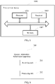
- FIG. 7 is a schematic diagram of a possible logical structure of a system information transmission apparatus 100.
- the system information transmission apparatus 100 may be applied to a first terminal device.
- the system information transmission apparatus 100 applied to the first terminal device includes a processing unit 101 and a receiving unit 102.
- the processing unit 101 is configured to determine on duration of the first terminal device.
- the receiving unit 102 is configured to receive, during the on duration of the first terminal device determined by the processing unit 101, system information sent by a second terminal device.
- the system information is system information required by the first terminal device, and the system information required by the first terminal device is a part or all of system information delivered by a base station of a camped-on cell or a serving cell of the second terminal device.
- the system information required by the first terminal device includes changed system information in the system information required by the first terminal device or all system information required by the first terminal device.
- the receiving unit 102 receives, on a paging occasion of the first terminal device, the system information sent by the second terminal device at least one time by using a resource in a sending resource pool, where the sending resource pool is configured or preconfigured by the base station by using a broadcast message.
- the resource in the sending resource pool is a resource that is used by the second terminal device to send a paging message, or the resource in the sending resource pool is a resource that is specially used by the second terminal device to send the system information to the first terminal device.
- the receiving unit 102 receives, on a paging occasion of the first terminal device, the system information sent by the second terminal device at least one time by using a dedicated resource, where the dedicated resource is configured by the base station for the second terminal device.
- the dedicated resource is determined by the base station based on a dedicated resource requested by the second terminal device from the base station and an indicated time domain resource location of the paging occasion.
- the on duration of the first terminal device is a time in which the first terminal receives a discovery message sent by the second terminal device, and the system information is carried in the discovery message sent by the second terminal device.
- the on duration of the first terminal device is a time in which the first device is in an RRC connected mode and may receive a message sent by the second terminal device, and the system information is carried in an RRC message that is sent by the base station and that is forwarded by the second terminal device.
- the receiving unit 102 is further configured to: before receiving the system information sent by the second terminal device, receive indication information sent by the second terminal device, where the indication information is used to indicate that the system information has changed.
- the on duration of the first terminal device is a time in which the first terminal receives a discovery message sent by the second terminal device, and the system information is carried in the discovery message sent by the second terminal device.
- the processing unit 101 may be a processor or a controller
- the receiving unit 102 may be a communications interface, a receiver, a transceiver circuit, or the like.
- the communications interface is a generic term, and may include one or more interfaces.
- the system information transmission apparatus 100 in this example of this application may be a first terminal device shown in FIG. 8 .
- the first terminal device shown in FIG. 8 may be a wearable device.
- FIG. 8 is a schematic diagram of a first terminal device 1000 according to an example of this application.
- the first terminal device 1000 may be configured to perform the method performed by the first terminal device in FIG. 2 to FIG. 5 .
- the first terminal device 1000 includes a processor 1001, a memory 1002, and a receiver 1003.
- the processor 1001, the memory 1002, and the receiver 1003 may be connected to each other through a bus system.
- the memory 1002 is configured to store a program, an instruction, or code.
- the processor 1001 is configured to execute the program in the memory 1002 to perform the following operations: controlling the receiver 1003 to receive, during on duration of the first terminal device, system information sent by a second terminal device, and implementing the steps and the functions implemented by the first terminal device in the foregoing implementations. Details are not described herein again.
- processor 1001 and the receiver 1003 refer to specific descriptions of the processing unit 101 and the receiving unit 102 in the foregoing implementations in FIG. 7 . Details are not described herein again.
- an example of this application further provides a system information transmission apparatus.
- FIG. 9 is a schematic diagram of a logical structure of a system information transmission apparatus 200 according to an example of this application.
- the system information transmission apparatus 200 may be applied to a first terminal device.
- the system information transmission apparatus 200 applied to the first terminal device includes a receiving unit 201 and a processing unit 202.
- the receiving unit 201 is configured to receive indication information sent by a second terminal device, where the indication information is used to indicate that system information has changed.
- the processing unit 202 obtains the system information according to the indication information received by the receiving unit 201.
- the processing unit 202 is configured to: when the receiving unit 201 receives the indication information, obtain the system information within a gap period of communication between the second terminal device and the first terminal device through a link between the first terminal device and a base station, where communication between the second terminal device and the first terminal device is suspended within the gap period.
- the gap period is configured by the first terminal device or the second terminal device, or if the first terminal device is in an RRC connected mode, the gap period is configured by the second terminal device or the base station for the first terminal device.
- the receiving unit 201 is further configured to: before the processing unit 202 obtains the system information within the gap period through the link between the first terminal device and the base station, obtain a cell identifier of a cell in which the second terminal device is located.
- the indication information is further used to indicate a type of the changed system information.
- the processing unit 202 is configured to: when the receiving unit 201 receives the indication information, obtain the system information through a link between the first terminal device and the second terminal device.
- the receiving unit 201 may be a communications interface, a receiver, a transceiver circuit, or the like.
- the communications interface is a generic term, and may include one or more interfaces.
- the processing unit 202 may be a processor or a controller.
- the system information transmission apparatus 200 in this example of this application may be a first terminal device shown in FIG. 10 .
- the first terminal device shown in FIG. 10 may be a wearable device.
- FIG. 10 is a schematic diagram of a first terminal device 2000 according to an example of this application.
- the first terminal device 2000 may be configured to perform the method performed by the first terminal device in FIG. 6 .
- the first terminal device 2000 includes a processor 2001, a memory 2002, and a receiver 2003.
- the processor 2001, the memory 2002, and the receiver 2003 may be connected to each other through a bus system.
- the memory 2002 is configured to store a program, an instruction, or code.
- the processor 2001 is configured to execute the program in the memory 2002 to perform the following operations: controlling the receiver 2003 to receive indication information sent by a second terminal device, performing a step of obtaining system information according to the indication information, and implementing the steps and the functions implemented by the first terminal device in the foregoing implementations. Details are not described herein again.
- processor 2001 and the receiver 2003 For specific implementations of the processor 2001 and the receiver 2003, refer to specific descriptions of the processing unit 202 and the receiving unit 201 in the foregoing implementations in FIG. 9 . Details are not described herein again.
- an example of this application further provides a system information transmission apparatus.
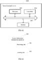
- FIG. 11 is a schematic diagram of a logical structure of a system information transmission apparatus 300 according to an example of this application.
- the system information transmission apparatus 300 may be applied to a second terminal device.
- the system information transmission apparatus 300 applied to the second terminal device includes a processing unit 301 and a sending unit 302.
- the processing unit 301 is configured to determine on duration of a first terminal device.
- the sending unit 302 is configured to send system information to the first terminal device during the on duration of the first terminal device determined by the processing unit 301.
- the system information is system information required by the first terminal device, and the system information required by the first terminal device is a part or all of system information delivered by a base station of a camped-on cell or a serving cell of the second terminal device.
- the system information required by the first terminal device includes changed system information in the system information required by the first terminal device or all system information required by the first terminal device.
- the sending unit 302 sends the system information at least one time on a paging occasion of the first terminal device by using a resource in a sending resource pool, where the sending resource pool is configured or preconfigured by the base station by using a broadcast message.
- the resource in the sending resource pool is a resource that is used by the second terminal device to send a paging message, or the resource in the sending resource pool is a resource that is specially used by the second terminal device to send the system information to the first terminal device.
- the sending unit 302 sends the system information at least one time on a paging occasion of the first terminal device by using a dedicated resource, where the dedicated resource is configured by the base station for the second terminal device.
- the dedicated resource is determined by the base station based on a dedicated resource requested by the second terminal device from the base station and an indicated time domain resource location of the paging occasion.
- the on duration of the first terminal device is a time in which the second terminal device sends a discovery message, and the system information is carried in the discovery message sent by the second terminal device.
- the on duration of the first terminal device is a time in which the first device is in an RRC connected mode and may receive a message sent by the second terminal device, and the system information is carried in an RRC message that is sent by the base station and that is forwarded by the second terminal device.
- the sending unit 302 is further configured to send indication information to the first terminal device before sending the system information to the first terminal device, where the indication information is used to indicate that the system information has changed.
- the processing unit 301 may be a processor or a controller
- the sending unit 302 may be a communications interface, a transmitter, a transceiver circuit, or the like.
- the communications interface is a generic term, and may include one or more interfaces.
- the system information transmission apparatus 300 in this embodiment of this application may be a second terminal device shown in FIG. 12 .
- the second terminal device shown in FIG. 12 may be an intelligent mobile terminal.
- FIG. 12 is a schematic diagram of a second terminal device 3000 according to an example of this application.
- the second terminal device 3000 may be configured to perform the method performed by the second terminal device in FIG. 2 to FIG. 5 .
- the second terminal device 3000 includes a processor 3001, a memory 3002, and a transmitter 3003.
- the processor 3001, the memory 3002, and the transmitter 3003 may be connected to each other through a bus system.
- the memory 3002 is configured to store a program, an instruction, or code.
- the processor 3001 is configured to execute the program in the memory 3002 to perform the following operations: determining on duration of a first terminal device, controlling the transmitter 3003 to send system information to the first terminal device during the on duration of the first terminal device, and implementing the steps and the functions implemented by the second terminal device in the foregoing implementations. Details are not described herein again.
- processor 3001 and the transmitter 3003 refer to specific descriptions of the processing unit 301 and the sending unit 302 in the foregoing implementations in FIG. 11 . Details are not described herein again.
- an example of this application further provides a system information transmission apparatus.
- FIG. 13 is a schematic diagram of a logical structure of a system information transmission apparatus 400 according to an example of this application.
- the system information transmission apparatus 400 may be applied to a second terminal device.
- the system information transmission apparatus 400 applied to the second terminal device includes a processing unit 401 and a sending unit 402.
- the processing unit 401 is configured to determine that system information required by a first terminal device changes.
- the sending unit 402 is configured to send indication information to the first terminal device when the processing unit 401 determines that the system information required by the first terminal device changes, where the indication information is used to indicate that the system information has changed.
- the indication information may be a paging message that is sent by the second terminal device to the first terminal device and that is used to indicate that the system information has changed.
- the processing unit 401 is further configured to: if the first terminal device is in an RRC connected mode, configure a gap period of communication between the second terminal device and the first terminal device for the first terminal device, where communication between the second terminal device and the first terminal device is suspended within the gap period, and the first terminal device obtains the system information through a link between the first terminal device and a base station.
- the processing unit 401 is further configured to: if the first terminal device is in an RRC idle mode, configure a gap period of communication between the second terminal device and the first terminal device for the first terminal device; or if the first terminal device is in an RRC connected mode, configure a gap period of communication between the second terminal device and the first terminal device for the first terminal device.
- the sending unit 402 is further configured to: if the first terminal device is in an RRC connected mode, forward a gap period of communication between the second terminal device and the first terminal device that is configured by a network device for the first terminal device, where communication between the second terminal device and the first terminal device is suspended within the gap period, and the first terminal device obtains the system information through a link between the first terminal device and the network device.
- the indication information is further used to indicate a type of the changed system information.
- the sending unit 402 is further configured to send the system information to the first terminal device through a link between the first terminal device and the second terminal device.
- the processing unit 401 may be a processor or a controller
- the sending unit 402 may be a communications interface, a transmitter, a transceiver circuit, or the like.
- the communications interface is a generic term, and may include one or more interfaces.
- the system information transmission apparatus 400 in this example of this application may be a second terminal device shown in FIG. 14 .
- the second terminal device shown in FIG. 14 may be an intelligent mobile terminal.
- FIG. 14 is a schematic diagram of a second terminal device 4000 according to an example of this application.
- the second terminal device 4000 may be configured to perform the method performed by the second terminal device in FIG. 6 .
- the second terminal device 4000 includes a processor 4001, a memory 4002, and a transmitter 4003.
- the processor 4001, the memory 4002, and the transmitter 4003 may be connected to each other through a bus system.
- the memory 4002 is configured to store a program, an instruction, or code.
- the processor 4001 is configured to execute the program in the memory 4002 to perform the following operations: when determining that system information required by a first terminal device changes, controlling the transmitter 4003 to send indication information to the first terminal device, where the indication information is used to indicate that the system information has changed; and implementing the steps and the functions implemented by the second terminal device in the foregoing implementations. Details are not described herein again.
- processor 4001 and the transmitter 4003 refer to specific descriptions of the processing unit 401 and the sending unit 402 in the foregoing implementations in FIG. 13 . Details are not described herein again.
- the examples of this application show merely simplified designs of the first terminal device and the second terminal device.
- the first terminal device and the second terminal device are not limited to the foregoing structures.
- the first terminal device may further include a transmitter
- the second terminal device may further include a receiver.
- the first terminal device and the second terminal device each may include any quantity of receivers, transmitters, processors, memories, and the like.
- first terminal device and the second terminal device in the examples of this application may be configured to implement the corresponding functions of the first terminal device and the second terminal device in the method embodiments in the embodiments of this application. Therefore, for a part that is not described in detail in the examples of this application, refer to related descriptions in the method embodiments. Details are not described in the embodiments of this application again.
- the processor may be a central processing unit (Central Processing Unit, CPU), or may be another general purpose processor, a digital signal processor (DSP), an application-specific integrated circuit (ASIC), a field programmable gate array (FPGA), another programmable logic device, a discrete gate, a transistor logic device, a discrete hardware component, or the like.
- the general purpose processor may be a microprocessor, or the processor may be any conventional processor or the like.
- the memory may include a read-only memory and a random access memory, and provide an instruction and data for the processor.
- a part of the memory may further include a non-volatile random access memory.
- the memory may further store device type information.
- the bus system may include a power bus, a control bus, a status signal bus, and the like in addition to a data bus.
- various types of buses in the figure are marked as the bus system.
- the steps in the foregoing method embodiments may be completed by using a hardware integrated logic circuit in the processor or by using an instruction in a form of software.
- the steps of the system information transmission method disclosed with reference to the embodiments of this application may be directly performed by a hardware processor, or may be performed by using a combination of hardware in the processor and a software module.
- the software module may be located in a mature storage medium in the art, such as a random access memory, a flash memory, a read-only memory, a programmable read-only memory, an electrically erasable programmable memory, or a register.
- the storage medium is located in the memory, and the processor reads information in the memory and completes the steps in the foregoing method embodiments in combination with hardware in the processor. To avoid repetition, details are not described herein again.
- the embodiments of this application may be provided as a method. Therefore, the examples of this application may use a form of hardware only embodiments, software only embodiments, or embodiments with a combination of software and hardware. Moreover, the examples of this application may use a form of a computer program product that is implemented on one or more computer-usable storage media (including but not limited to a magnetic disk memory, a CD-ROM, an optical memory, and the like) that include computer-usable program code.
- a computer-usable storage media including but not limited to a magnetic disk memory, a CD-ROM, an optical memory, and the like
- These computer program instructions may be provided for a general-purpose computer, a dedicated computer, an embedded processor, or a processor of any other programmable data processing device to generate a machine, so that the instructions executed by a computer or a processor of any other programmable data processing device generate an apparatus for implementing a specific function in one or more processes in the flowcharts and/or in one or more blocks in the block diagrams.
- These computer program instructions may be stored in a computer readable memory that can instruct the computer or any other programmable data processing device to work in a specific manner, so that the instructions stored in the computer readable memory generate an artifact that includes an instruction apparatus.
- the instruction apparatus implements a specific function in one or more processes in the flowcharts and/or in one or more blocks in the block diagrams.
- These computer program instructions may be loaded onto a computer or another programmable data processing device, so that a series of operations and steps are performed on the computer or the another programmable device, thereby generating computer-implemented processing. Therefore, the instructions executed on the computer or the another programmable device provide steps for implementing a specific function in one or more processes in the flowcharts and/or in one or more blocks in the block diagrams.
Description
- This application relates to the field of communications technologies, and in particular, to system information transmission and reception methods.
- Document
US 2016/0007271 A1 discloses methods and devices for providing system information of a cellular communication network. DocumentWO 2011/099744 A2 discloses a method and an apparatus of transmitting and receiving system information in a wireless communication system. DocumentWO 2011/100707 A1 discloses techniques for reading and caching of system information to reduce a call setup delay. - A device-to-device (Device-to-Device, D2D) communication mode is a communication mode in which a transmit end directly sends data to a receive end without forwarding by a base station or a cellular network. A relatively special mode in the D2D communication mode is a UE-to-network relay scenario. In the UE-to-network relay scenario, a terminal device (for example, user equipment (User Equipment, UE)) is connected to a network by using another terminal device having a relay function. Usually, the former is referred to as a remote terminal device (Remote UE), and the latter is referred to as a relay terminal device (Relay UE).
- In the UE-to-network relay scenario, if system information of a camped-on cell or a serving cell of the remote terminal device changes, a base station of the camped-on cell or the serving cell of the remote terminal device sends a paging message to the remote terminal device, and indicates, by using the paging message, that the system information changes. After receiving the paging message sent by the base station, the remote terminal device determines that the system information changes and obtains changed system information. The remote terminal device needs to be located in coverage of a cell to obtain the changed system information, and receives the changed system information through a cellular link between the remote terminal device and the base station.
- The remote terminal device receives the system information in the foregoing manner, resulting in relatively high complexity and relatively high power consumption.
- Embodiments of this application provide a system information transmission method and a system information reception method, to reduce complexity and power consumption of receiving system information by a remote terminal device.
- The present invention is defined by the independent claims. The following aspects are not presented as embodiments of the invention, but as examples useful for understanding the invention.
- According to a first aspect, a system information reception method is provided. The method comprises, determining, by a first terminal device, on duration of the first terminal device, receiving, by the first terminal device during the on duration of the first terminal device, first system information sent by a second terminal device, wherein the first system information is a part or all of second system information delivered by a base station. The method is further characterized in that before the receiving, by the first terminal device, first system information sent by a second terminal device, the method further comprises, receiving, by the first terminal device, indication information sent by the second terminal device, wherein the indication information indicates that the first system information has changed, wherein the on duration of the first terminal device is a paging occasion of the first terminal device, wherein the receiving, by the first terminal device during the on duration of the first terminal device, first system information sent by a second terminal device comprises, receiving, by the first terminal device during the on duration of the first terminal device, the first system information, wherein the first system information is sent by the second terminal device at least one time by using a resource in a sending resource pool, wherein the sending resource pool is configured by the base station by using a broadcast message.
- According to a second aspect, a system information transmission method is provided. The method comprises determining, by a second terminal device, on duration of a first terminal device, and sending, by the second terminal device, first system information to the first terminal device during the on duration of the first terminal device, wherein the first system information is a part or all of second system information delivered by a base station. The method is characterized in that before the sending, by the second terminal device, first system information to the first terminal device, the method further comprises, sending, by the second terminal device, indication information to the first terminal device, wherein the indication information indicates that the first system information has changed, wherein the on duration of the first terminal device is a paging occasion of the first terminal device, wherein the sending (S102), by the second terminal device, first system information to the first terminal device during the on duration of the first terminal device comprises, sending, by the second terminal device, the first system information at least one time during the on duration of the first terminal device by using a resource in a sending resource pool, wherein the sending resource pool is configured by the base station by using a broadcast message.
-
-
FIG. 1 is a schematic architectural diagram of an application scenario of a system information transmission method according to this application; -
FIG. 2 is an implementation flowchart of a system information transmission method according to an embodiment of this application; -
FIG. 3 is an implementation flowchart of a method for transmitting system information by a first terminal device and a second terminal device on a paging occasion according to an embodiment of this application; -
FIG. 4 is an implementation flowchart of a method for transmitting system information by a first terminal device and a second terminal device by using a discovery message according to an example of this application; -
FIG. 5 is an implementation flowchart of a method for transmitting system information by a first terminal device and a second terminal device by using an RRC message according to an example of this application; -
FIG. 6 is another implementation flowchart of a system information transmission method according to an example of this application; -
FIG. 7 is a schematic structural diagram of a system information transmission apparatus according to this application; -
FIG. 8 is a schematic structural diagram of a first terminal according to this application; -
FIG. 9 is a schematic structural diagram of another system information transmission apparatus according to this application; -
FIG. 10 is a schematic structural diagram of another first terminal according to this application; -
FIG. 11 is a schematic structural diagram of still another system information transmission apparatus according to this application; -
FIG. 12 is a schematic structural diagram of a second terminal according to this application; -
FIG. 13 is a schematic structural diagram of still another system information transmission apparatus according to this application; and -
FIG. 14 is a schematic structural diagram of another second terminal according to this application. - The following describes the embodiments of this application with reference to accompanying drawings.
- A system information transmission method provided in the embodiments of this application may be applied to a communication scenario in which two devices directly communicate with each other. In the embodiments of this application, devices that directly communicate with each other may include various handheld devices, in-vehicle devices, wearable devices, or computing devices with a wireless communication function, or other processing devices connected to a wireless modem, and user equipment (User Equipment, UE) in various forms, mobile stations (Mobile station, MS) in various forms, terminals (terminal) in various forms, terminal devices (Terminal Equipment) in various forms, and the like. For ease of description, the devices that directly communicate with each other are referred to as terminal devices below in the embodiments of this application.
- A UE-to-network relay scenario is a typical application scenario in which two devices directly communicate with each other.
FIG. 1 is a schematic architectural diagram of the UE-to-network relay scenario. In the application scenario shown inFIG. 1 , a link between a network device and a first terminal device and a link between the network device and a second terminal device may be referred to as cellular links or may be referred to as an uplink and a downlink, and a link between the first terminal device and the second terminal device may be referred to as a sidelink. In this application, the second terminal device is a terminal device that directly interacts with the network device and may also be referred to as a relay terminal device, and the first terminal device is a terminal device that communicates with the network device by using the second terminal device and may also be referred to as a remote terminal device. In existing layer 3 UE-to-network relay communication, control signaling of the first terminal device may interact with the network device through a cellular link, and user data of the first terminal device may interact with the network device through a sidelink. That is, user data between the first terminal device and the network device may be forwarded to the first terminal device by using the second terminal device, or user data between the second terminal device and the network device may be forwarded to the network device by using the first terminal device. In layer 2 UE-to-network relay communication, both control signaling and user data of the second terminal device may interact with the network device through a sidelink. - It may be understood that the network device in
FIG. 1 is an apparatus that is deployed in a radio access network and provides a wireless communication function for a terminal, and may be a base station (base station, BS), for example, may include various forms such as a macro base station, a micro base station, a relay station, and an access point. In a system using different radio access technologies, a name of a device with a base station function may vary. For example, the device is referred to as an evolved NodeB (evolved NodeB, eNB or eNodeB for short) in a long term evolution (Long Term Evolution, LTE) network, or is referred to as a NodeB (NodeB) in a third generation 3G network. For ease of description, in the embodiments of this application, the network device that communicates with the first terminal device and the second terminal device is referred to as a base station below. - Based on the application scenario shown in
FIG. 1 , if system information of a camped-on cell or a serving cell of the first terminal device and the second terminal device changes, or handover (handover) occurs between the first terminal device and the second terminal device, it may be understood that cell system information changes. In this case, the first terminal device and the second terminal device need to re-obtain the system information. The serving cell is a cell to which a terminal device is connected when the terminal device is in a radio resource control (Radio Resource Control, RRC) connected mode. The camped-on cell is a cell on which a terminal device camps when the terminal device is in an RRC idle mode. The system information is a message that is periodically broadcast by the base station to all terminal devices in a cell on a broadcast channel. The system information is classified into a master information block (Master Information Block, MIB) and a plurality of system information blocks (System Information Blocks, SIB). The master information block includes a limited quantity of most important and commonly used transmission parameters for reading other cell information. The system information block includes other required parameters, including 20 system information blocks: a SIB1 to a SIB20. - Based on the application scenario shown in
FIG. 1 , for the first terminal device, if a connection is established between the first terminal device and the second terminal device, it may be considered that the first terminal device may camp on the second terminal device connected to the first terminal device. When the cell system information has changed, the first terminal device may obtain the system information through a cellular link or may obtain the system information by using the second terminal device. - In an embodiment of this application, when cell system information has changed, the first terminal device receives, during on duration of the first terminal device, system information sent by the second terminal device, so that the first terminal device can receive the system information through a sidelink between the first terminal device and the second terminal device without a need to maintain a cellular link, thereby reducing complexity and power consumption of system information transmission.
- In an alternative example, when cell system information has changed and the first terminal device has only one receive radio frequency chain, the first terminal device may obtain system information within a gap period between the second terminal device and the first terminal device through a link between the first terminal device and the base station. Communication between the second terminal device and the first terminal device is suspended within the gap period, so that the changed system information can be received through a cellular link. In addition, the first terminal device may maintain the cellular link only within the gap period, and does not need to maintain the cellular link within a period other than the gap period, thereby reducing complexity and power consumption of system information transmission to some extent.
- It may be understood that the system information transmission method provided in the embodiments of this application is not limited to the application scenario shown in
FIG. 1 , and may also be applied to an application scenario in which two other devices directly communicate with each other, for example, a short-range communication scenario in which a Bluetooth technology or a wireless fidelity (Wireless Fidelity, WiFi) technology is used. - The following describes a specific implementation method in which the first terminal device receives the system information by using the second terminal device or the cellular link with reference to actual application in the embodiments of this application.
-
FIG. 2 is an implementation flowchart of a system information transmission method according to an embodiment of this application. Referring toFIG. 2 , the method includes the following steps. - S101: A second terminal device determines on duration of a first terminal device.
- The on duration of the first terminal device is a time in which the first terminal device may send and receive a message. The on duration is a paging occasion (Paging Occasion, PO) of the first terminal device in an RRC idle mode, or may be a time in which the first terminal device receives a discovery message sent by the second terminal device, or may be a time in which the first terminal device in an RRC connected mode receives a message sent by the second terminal device, including a time in which the first terminal device that is in an RRC connected mode and is configured with discontinuous reception (Discontinuous Reception: DRX) is in DRX on duration (on duration), or may be another time in which the first terminal device may receive a message sent by the second terminal device. That the second terminal device determines the on duration of the first terminal device may be understood as that the second terminal device calculates the on duration of the first terminal device, or the second terminal device obtains a configuration of the on duration of the first terminal device.
- S102: The second terminal device sends system information to the first terminal device during the on duration of the first terminal device.
- S103: The first terminal device receives, during the on duration of the first terminal device, the system information sent by the second terminal device.
- A part of system information delivered by a base station of a camped-on cell or a serving cell of the second terminal device is required by all first terminal devices that complete establishment of a direct link to the second terminal device. In this embodiment of this application, this part of system information may be referred to as basic system information, for example, cell access related information IE cellAccessRelatedInfo in a SIB1. Another part of system information delivered by the base station of the camped-on cell or the serving cell of the second terminal device has different requirements for first terminal devices of different types, capabilities, and service requirements. In this embodiment of this application, this part of system information may be referred to as specific system information. For example, system information required by a first terminal device that supports extended access control (Extended access class barring, EAB) is a SIB14; system information required by a first terminal device that supports a multimedia broadcast multicast service (Multimedia Broadcast Multicast Service, MBMS) is a SIB13, a SIB15, and the like; and system information required by a first terminal device that supports collaboration between a universal mobile telecommunications system (Universal Mobile Telecommunication System, UMTS) evolved universal terrestrial radio access network (Evolved Universal Terrestrial Radio Access Network, E-UTRAN) and a wireless local area network (Wireless Local Area Networks, WLAN) is a SIB17 and the like. A first terminal device may not require specific system information, and specific system information required by different first terminal devices may be the same or partially the same.
- System information that needs to be obtained by a first terminal device includes basic system information and specific system information required by the first terminal device, and the first terminal device does not need to obtain specific system information of another first terminal device. To reduce signaling overheads of transmitting system information between the first terminal device and the second terminal device, the second terminal device may send, to the first terminal device, system information required by the first terminal device, where the system information required by the first terminal device may be a part or all of system information delivered by the base station of the camped-on cell or the serving cell of the second terminal device. The second terminal device may store specific system information required by the first terminal device. The system information required by the first terminal device may be changed system information in the system information required by the first terminal device or all system information required by the first terminal device.
- When sending the system information to the first terminal device during the on duration of the first terminal device, the second terminal device may send the system information by using a broadcast address, in other words, send the system information to the first terminal device in a broadcast manner, so that all first terminal devices connected to the second terminal device can receive the system information. The second terminal device may alternatively send the system information to the first terminal device by using a multicast address, in other words, send the system information to the first terminal device in a multicast manner, so that some first terminal devices connected to the second terminal device can receive the system information. The second terminal device may alternatively send the system information to the first terminal device by using a unicast address, in other words, send the system information to the first terminal device in a unicast manner, so that a first terminal device connected to the second terminal device can receive the system information sent by the second terminal device.
- In this embodiment of this application, when cell system information has changed, the first terminal device receives, during the on duration of the first terminal device, the system information sent by the second terminal device, so that the first terminal device can receive the system information through a sidelink between the first terminal device and the second terminal device without a need to maintain a cellular link, thereby reducing complexity and power consumption of system information transmission.
- With reference to actual application, the embodiments of this application describe below an implementation process of transmitting system information between the second terminal device and the first terminal device in various scenarios in which the on duration of the first terminal is the paging occasion of the first terminal device, the on duration of the first terminal is a time in which the second terminal device sends the discovery message, and the on duration of the first terminal is a time in which the first terminal device is in an RRC connected mode and may receive the message sent by the second terminal device.
- First, for a scenario in which on duration of a first terminal is a paging occasion of the first terminal device, an implementation process in which a second terminal sends system information to the first terminal device on the paging occasion of the first terminal device, and the first terminal device receives, on the paging occasion of the first terminal, the system information sent by the second terminal device is described.
-
FIG. 3 is an implementation flowchart of a method for transmitting system information by a first terminal device and a second terminal device on a paging occasion according to an embodiment of this application. As shown inFIG. 3 , the method includes the following steps. - S201: A second terminal device determines a resource that is used to send system information to a first terminal device on a paging occasion of the first terminal device.
- In an implementation, the second terminal device may send the system information to the first terminal device by using a dedicated resource.
- The dedicated resource is determined by a base station based on a dedicated resource requested by the second terminal device from the base station and a time domain location that is of the paging occasion and that is indicated by the second terminal device to the base station.
- The second terminal device may request the dedicated resource from the base station, and indicate the time domain location of the paging occasion, and the second terminal device indicates the time domain location of the paging occasion to the base station, so that the base station allocates the dedicated resource to the paging occasion corresponding to the time domain location. The second terminal device indicates the time domain location of the paging occasion to the base station may be: the second terminal device may indicate, to the base station, an S-temporary mobile subscriber identity (S-Temporary Mobile Subscriber Identity, s-TMSI), a user equipment-specific discontinuous reception cycle (UE-specific DRX cycle), or a specific subframe index such as 0, 4, 5, or 9, and other information that may be used to determine the time domain location of the paging occasion, and the base station may determine the time domain location of the paging occasion by using the indicated information. The implementation in which the second terminal device uses the dedicated resource is applicable to a scenario in which the second terminal device is in an RRC connected mode.
- The second terminal device uses a resource in a sending resource pool that is configured or preconfigured by a base station by using a broadcast message as a resource that is used by the second terminal device to send the system information to the first terminal device.
- In this embodiment of this application, a time domain location of the resource that is in the sending resource pool and that is used by the second terminal device overlaps with a time domain location of the paging occasion of the first terminal device, so that when the second terminal device sends the system information by using the resource in the sending resource pool, the first terminal device can receive the system information sent by the second terminal device.
- The resource in the sending resource pool may be a resource that is used by the second terminal device to send a paging message. The second terminal device may directly send the system information by using a resource that is used by a paging message originally sent by the second terminal device, and use the sending resource used by the original paging message as the resource in the sending resource pool. The second terminal device may alternatively add the system information to the original paging message to obtain a new paging message, and use a sending resource used by the new paging message as the resource in the sending resource pool.
- The resource in the sending resource pool may be alternatively a resource that is specially used by the second terminal device to send the system information to the first terminal device. When a sending resource pool that is specially used to send the system information is allocated to the second terminal device, the base station may schedule a resource in the resource pool to another terminal device for use when the second terminal device does not use the resource (when the system information does not change), thereby reducing resource waste.
- In this embodiment of this application, when the base station configures the sending resource pool for the second terminal device, the second terminal device may be in an RRC connected mode or an RRC idle mode. Regardless of whether the second terminal device is in an RRC connected mode or an RRC idle mode, the second terminal device can select, from the sending resource pool, a resource used for sending the system information.
- S202: The second terminal device sends the system information to the first terminal device on the paging occasion of the first terminal device by using a resource in a sending resource pool, where the sending resource pool is configured by a base station by using a broadcast message.
- In this embodiment of this application, the second terminal device may send the system information on one or more paging occasions of the first terminal device, to ensure that the first terminal device can receive the system information sent by the second terminal device. The second terminal device may send the system information on the one or more paging occasions of the first terminal device in a broadcast manner, or the second terminal device may send the system information on the one or more paging occasions of the first terminal device in a multicast manner, or the second terminal device may send the system information on the one or more paging occasions of the first terminal device in a unicast manner.
- In this embodiment of this application, the second terminal device may send only changed system information to the first terminal device, thereby reducing signaling overheads. The second terminal device may obtain the changed system information in one of the following manners:
- A: The base station indicates the changed system information in a paging message, and the second terminal device may determine the changed system information by receiving a paging message sent by the base station. The base station may indicate the changed system information in the paging message in the following manner: extending IE system Info Modification to indicate the changed system information in content of the IE system Info Modification; or newly adding an IE to indicate the changed system information in content of the newly added IE.
- B: The base station indicates the changed system information in a SIB1 message, and the second terminal device may determine the changed system information by receiving a SIB1 message sent by the base station. The base station may indicate the changed system information in the SIB1 message in the following manner: extending IE system Info Value Tag to indicate the changed system information in content of the IE system Info Value Tag; or newly adding an IE to indicate the changed system information in content of the newly added IE.
- C: The second terminal device receives system information sent by the base station, and compares the newly received system information with currently stored original system information, to further determine the changed system information.
- In the two manners A and B of determining the changed system information, the second terminal device may receive only the changed system information without a need to compare system information, thereby reducing power consumption.
- In this embodiment of this application, the method further includes the following step S203:
- S203: The second terminal device sends indication information to the first terminal device, where the indication information indicates that the system information has changed. The indication information may indicate that the system information has changed, or indicate a primary notification and/or a secondary notification of an earthquake and tsunami warning system (Earthquake and Tsunami Warning System, ETWS), or indicate a commercial mobile alert service (Commercial Mobile Alert Service, CMAS) notification, or indicate that an extended access barring (Extended Access Barring, EAB) parameter changes, or the like. The indication information may be carried in a paging message, or may be carried in a discovery message, or may be carried in a newly added message. In this embodiment of this application, S203 is not an optional step. When step S203 is included, the second terminal device sends, to the first terminal device, the indication information that indicates that the system information has changed, so that the first terminal device receives the system information only when the first terminal device needs to receive the system information, thereby reducing signaling overheads.
- S204: The first terminal device determines the paging occasion of the first terminal device, and receives, on the paging occasion of the first terminal device, the system information sent by the second terminal device by using the resource in the sending resource pool.
- In this embodiment of this application, the second terminal device sends the system information to the first terminal device on the paging occasion of the first terminal device, so that the first terminal device can receive the system information through a sidelink between the first terminal device and the second terminal device without a need to maintain a cellular link, thereby reducing complexity and power consumption of system information transmission. In addition, the second terminal device sends the system information to the first terminal device on the paging occasion of the first terminal device, and regardless of whether the first terminal device is in an RRC connected mode or an RRC idle mode, the first terminal device can receive the system information sent by the second terminal device. This embodiment can be applied to wide scenarios.
- Second, in an alternative example for a scenario in which on duration of a first terminal is a time in which the second terminal device sends a discovery message, an implementation process in which the second terminal adds system information to the discovery message sent by the second terminal device and sends the discovery message to the first terminal device, and the first terminal obtains the system information by receiving the discovery message sent by the second terminal device is described.
-
FIG. 4 is an implementation flowchart of a method for transmitting system information by a first terminal device and a second terminal device by using a discovery message according to an alternative example. As shown inFIG. 4 , the method includes the following steps. - S301: A second terminal device determines a discovery message that is used to send system information.
- In this example of this application, the second terminal device may add the system information to a reserved bit in an existing discovery message, or the second terminal device may establish a discovery message that is specially used for carrying the system information. A bit in the discovery message that is specially used for carrying the system information may carry the system information, and carry some necessary information such as a destination address.
- In this example of this application, the second terminal device may add the system information to one or more discovery messages.
- S302: The second terminal device broadcasts the system information to a first terminal device by using the discovery message.
- S303: The first terminal device receives, within a time of receiving the discovery message sent by the second terminal device, the discovery message that is sent by the second terminal device and that carries the system information. The first terminal device needs to receive the discovery message regardless of whether the first terminal device is in an RRC connected mode or an RRC idle mode.
- In this example of this application, the second terminal device adds the system information to the discovery message and sends the discovery message to the first terminal device, so that the first terminal device can receive the system information through a sidelink between the first terminal device and the second terminal device without a need to maintain a cellular link, thereby reducing complexity and power consumption of system information transmission.
- Third, in an example of this application, for a scenario in which on duration of a first terminal device is a time in which the first terminal device in an RRC connected mode receives a message sent by a second terminal device, including a time in which the first terminal device that is in an RRC connected mode and that is configured with discontinuous reception (Discontinuous Reception: DRX) is in DRX on duration (on duration), an implementation process in which the second terminal device forwards, to the first terminal device, an RRC message that is sent by a base station and that carries system information, and the first terminal obtains the system information by receiving the RRC message that is sent by the base station and that is forwarded by the second terminal device is described.
-
FIG. 5 is an implementation flowchart of a method for transmitting system information by a first terminal device and a second terminal device by using an RRC message according to an example of this application. As shown inFIG. 5 , the method includes the following steps. - S401: A base station determines that system information has changed, and adds system information required by a first terminal device to an RRC message.
- The RRC message that carries the system information required by the first terminal device may be an RRC dedicated message.
- Specifically, the system information required by the first terminal device may be carried in an RRC reconfiguration message in the RRC dedicated message, and the RRC reconfiguration message that carries the system information required by the first terminal device may be sent to the first terminal device by using a layer 2 relay protocol stack.
- S402: The base station sends, to a second terminal device, the RRC message that carries the system information required by the first terminal device.
- S403: The second terminal device receives the RRC message sent by the base station, and forwards, to the first terminal device, the RRC message that carries the system information required by the first terminal device.
- S404: The first terminal device receives the RRC message that carries the system information required by the first terminal device, and obtains the required system information.
- In this example of this application, the second terminal device needs to obtain a resource that is used to forward the RRC message to the first terminal device. To reduce signaling overheads of requesting a resource and allocating a resource by the second terminal device, the base station may configure, for the RRC message that is sent to the second terminal device and that carries the system information required by the first terminal device, the resource that is used to forward the RRC message.
- In this example of this application, the second terminal device forwards, to the first terminal device, the RRC message that is sent by the base station and that carries the system information, so that the first terminal device can receive the system information through a sidelink between the first terminal device and the second terminal device without a need to maintain a cellular link, thereby reducing complexity and power consumption of system information transmission. In addition, in the solution in which the system information is carried in the RRC message, regardless of whether the first terminal device is in coverage of a cell or is out of coverage of a cell, the first terminal device can obtain the system information in this manner as long as the first terminal device is in an RRC connected mode. An implementation process is simple, and an existing standard protocol is slightly changed, thereby reducing signaling overheads and resource waste.
- In this example of this application, when cell system information changes, and the second terminal device determines that the cell system information has changed, the second terminal device may send a direct link release message (DIRECT_COMMUNICATION_RELEASE) to the first terminal device in an RRC idle mode, and indicate that a reason for releasing a link is that the system information has changed. After receiving the direct link release message, the first terminal device determines, based on the direct link release message, that the system information has changed. The first terminal device releases a direct link between the first terminal device and the second terminal device, re-establishes the direct link between the first terminal device and the second terminal device, and obtains the changed system information when or after the direct link between the first terminal device and the second terminal device is re-established, or a camped-on cell or a serving cell that camps on the second terminal device receives the changed system information through a cellular link.
- In another example of this application, when cell system information changes and the first terminal device has only one receive radio frequency chain, the first terminal device may obtain the system information within a gap period of communication between the second terminal device and the first terminal device through a link between the first terminal device and the base station.
-
FIG. 6 is another implementation flowchart of a system information transmission method according to an example of this application. As shown inFIG. 6 , the method includes the following steps. - S501: A second terminal device determines that system information required by a first terminal device haschanged, and the second terminal device sends indication information to the first terminal device, where the indication information is used to indicate that the system information has changed.
- The indication information may indicate that the system information has changed, or indicate a primary notification and/or a secondary notification of an earthquake and tsunami warning system ETWS, or indicate a commercial mobile alert service CMAS notification, or indicate that an extended access barring EAB parameter has changed, or the like. The indication information may be carried in a paging message, or may be carried in a discovery message, or may be carried in a newly added message.
- The indication information may be a paging message that is sent by the second terminal device to the first terminal device and that is used to indicate that the system information has changed. The paging message that is used to indicate that the system information changes may include IE system Info Modification and IE system Info Modification is set to true, to indicate that the system information has changed. The paging message that is used to indicate that the system information has changed may further include IE etws-Indication and IE etws-Indication is set to true, to indicate that earthquake and tsunami warning system (Earthquake and Tsunami Warning System, ETWS) system information changes. Alternatively, the paging message that is used to indicate that the system information has changed may further include IE cmas-Indication and IE cmas-Indication is set to true, to indicate that commercial mobile alert service (Commercial Mobile Alert Service, CMAS) system information changes, or the paging message that is used to indicate that the system information has changed may further include IE eab-Param Modification and IE eab-Param Modification is set to true, to indicate that extended access barring (Extended Access Barring, EAB) system information changes.
- S502: The first terminal device receives the indication information sent by the second terminal device, and obtains the system information according to the indication information.
- The first terminal device may receive the system information through a sidelink between the first terminal device and the second terminal device according to the indication information.
- If the first terminal device has only one receive radio frequency chain (RX chain), the first terminal device may obtain the system information according to the indication information within a gap period of communication between the second terminal device and the first terminal device through a link between the first terminal device and a base station. Communication between the second terminal device and the first terminal device is suspended within the gap period. The second terminal device and the first terminal device may still communicate with each other through the sidelink outside the gap period. It should be noted that the gap period is to distinguish between a time of communication between the first terminal device and the second terminal device and a time of communication between the first terminal device and the base station. It may be understood that, in another possible implementation, the second terminal device communicates with the first terminal device within the gap period, and communication between the second terminal device and the first terminal device is suspended within the gap period.
- In this example of this application, if the first terminal device is in an RRC idle mode and has no data service, the gap period may be configured by the first terminal device, or may be configured or preconfigured by the second terminal device. A time domain location of the gap period configured by the first terminal device does not overlap with a time domain location of on duration of the first terminal device such as a paging occasion of the first terminal, in other words, the first terminal device may select any time period in a sleep time of the first terminal device as the gap period, and switch to a cellular link within the gap period to receive the system information. A time domain location of the gap period configured by the second terminal device does not overlap with a time domain location of on duration of the first terminal device such as a paging occasion of the first terminal, in other words, the second terminal device may select any time period in a sleep time of the first terminal device as the gap period, and switch to a cellular link within the gap period to receive the system information.
- If the first terminal device is in an RRC connected mode, the gap period may be configured by the second terminal device or the base station for the first terminal device. If the gap period is configured by the base station, the base station needs to forward configuration information of the gap period to the second terminal device. If the gap period is configured by the second terminal device, the second terminal device may send configuration information of the gap period to the base station. The second terminal device or the base station may control not to send data to the first terminal device within the gap period, or the second terminal device or the base station may control not to schedule the first terminal device within the gap period. The gap period configured by the second terminal device or the base station for the first terminal device may be one or more modification periods, or may be periods of some system information windows (SI window), or may be a periodically repeated time period, or may be another customized time period.
- In an example, to enable the first terminal device to accurately and quickly switch to a cellular link to obtain the system information, the first terminal device needs to obtain a cell identifier of a serving cell of the second terminal device. Therefore, in this example of this application, before the system information is obtained through the link between the first terminal device and the base station, the first terminal device may obtain a cell identifier of a cell in which the second terminal device is located. Certainly, in this example of this application, in addition to obtaining the cell identifier, the first terminal device may obtain other assistance information that helps the first terminal device quickly find the cell in which the second terminal device is located.
- In another possible implementation, in addition to sending, to the first terminal device, the indication information that is used to indicate that the system information has changed, the second terminal device may indicate the changed system information to the first terminal, for example, one or more SIBs change or one or more IEs in a SIB change, and the changed system information may be carried in the indication information, so that the first terminal device needs to receive only the system information required by the first terminal device, and does not need to receive all system information, thereby reducing signaling overheads.
- In this example of this application, when cell system information changes, and the first terminal device has only one receive radio frequency chain, the first terminal device may suspend communication within the gap period of communication between the second terminal device and the first terminal device, and obtain the system information through the link between the first terminal device and the base station, to receive the changed system information through the cellular link. In addition, the first terminal device may maintain the cellular link only within the gap period, and does not need to maintain the cellular link within a period other than the gap period, thereby reducing complexity and power consumption of system information transmission to some extent.
- The foregoing mainly describes the solutions provided in the embodiments of this application from the perspective of interaction between the first terminal device and the second terminal device. It may be understood that to implement the foregoing functions, the first terminal device and the second terminal device include corresponding hardware structures and/or software units for performing the functions. With reference to the units and the algorithm steps in the examples described in the embodiments disclosed in this application, the embodiments of this application can be implemented by hardware or a combination of hardware and computer software. Whether a function is performed by hardware or hardware driven by computer software depends on particular applications and design constraints of the technical solutions. A person skilled in the art may use different methods to implement the described functions for each particular application, but it should not be considered that the implementation falls beyond the scope of the technical solutions in the embodiments of this application.
- In the embodiments of this application, functional units of the first terminal device and the second terminal device may be obtained through division based on the foregoing method examples. For example, each functional unit may be obtained through division based on each corresponding function, or two or more functions may be integrated into one processing unit. The integrated unit may be implemented in a form of hardware, or may be implemented in a form of a software functional unit. It should be noted that in the embodiments of this application, unit division is an example and is merely logical function division. In actual implementation, another division manner may be used.
- Based on a same concept as the foregoing method embodiment, an example of this application provides a system information transmission apparatus.
- When an integrated unit is used,
FIG. 7 is a schematic diagram of a possible logical structure of a systeminformation transmission apparatus 100. The systeminformation transmission apparatus 100 may be applied to a first terminal device. Referring toFIG. 7 , the systeminformation transmission apparatus 100 applied to the first terminal device includes aprocessing unit 101 and a receivingunit 102. Theprocessing unit 101 is configured to determine on duration of the first terminal device. The receivingunit 102 is configured to receive, during the on duration of the first terminal device determined by theprocessing unit 101, system information sent by a second terminal device. - The system information is system information required by the first terminal device, and the system information required by the first terminal device is a part or all of system information delivered by a base station of a camped-on cell or a serving cell of the second terminal device.
- The system information required by the first terminal device includes changed system information in the system information required by the first terminal device or all system information required by the first terminal device.
- In a possible implementation, the receiving
unit 102 receives, on a paging occasion of the first terminal device, the system information sent by the second terminal device at least one time by using a resource in a sending resource pool, where the sending resource pool is configured or preconfigured by the base station by using a broadcast message. - The resource in the sending resource pool is a resource that is used by the second terminal device to send a paging message, or the resource in the sending resource pool is a resource that is specially used by the second terminal device to send the system information to the first terminal device.
- In another possible implementation, the receiving
unit 102 receives, on a paging occasion of the first terminal device, the system information sent by the second terminal device at least one time by using a dedicated resource, where the dedicated resource is configured by the base station for the second terminal device. - The dedicated resource is determined by the base station based on a dedicated resource requested by the second terminal device from the base station and an indicated time domain resource location of the paging occasion.
- In still another possible implementation, the on duration of the first terminal device is a time in which the first terminal receives a discovery message sent by the second terminal device, and the system information is carried in the discovery message sent by the second terminal device.
- In still another possible implementation, the on duration of the first terminal device is a time in which the first device is in an RRC connected mode and may receive a message sent by the second terminal device, and the system information is carried in an RRC message that is sent by the base station and that is forwarded by the second terminal device.
- In still another possible implementation, the receiving
unit 102 is further configured to:
before receiving the system information sent by the second terminal device, receive indication information sent by the second terminal device, where the indication information is used to indicate that the system information has changed. - In still another possible implementation, the on duration of the first terminal device is a time in which the first terminal receives a discovery message sent by the second terminal device, and the system information is carried in the discovery message sent by the second terminal device.
- When a form of hardware is used, the
processing unit 101 may be a processor or a controller, and the receivingunit 102 may be a communications interface, a receiver, a transceiver circuit, or the like. The communications interface is a generic term, and may include one or more interfaces. - When the
processing unit 101 is the processor and the receivingunit 102 is the receiver, the systeminformation transmission apparatus 100 in this example of this application may be a first terminal device shown inFIG. 8 . The first terminal device shown inFIG. 8 may be a wearable device. -
FIG. 8 is a schematic diagram of afirst terminal device 1000 according to an example of this application. Thefirst terminal device 1000 may be configured to perform the method performed by the first terminal device inFIG. 2 to FIG. 5 . As shown inFIG. 8 , thefirst terminal device 1000 includes aprocessor 1001, amemory 1002, and areceiver 1003. Theprocessor 1001, thememory 1002, and thereceiver 1003 may be connected to each other through a bus system. Thememory 1002 is configured to store a program, an instruction, or code. Theprocessor 1001 is configured to execute the program in thememory 1002 to perform the following operations: controlling thereceiver 1003 to receive, during on duration of the first terminal device, system information sent by a second terminal device, and implementing the steps and the functions implemented by the first terminal device in the foregoing implementations. Details are not described herein again. - For specific implementations of the
processor 1001 and thereceiver 1003, refer to specific descriptions of theprocessing unit 101 and the receivingunit 102 in the foregoing implementations inFIG. 7 . Details are not described herein again. - Based on a same concept as the foregoing method embodiment, an example of this application further provides a system information transmission apparatus.
- When an integrated unit is used,
FIG. 9 is a schematic diagram of a logical structure of a systeminformation transmission apparatus 200 according to an example of this application. The systeminformation transmission apparatus 200 may be applied to a first terminal device. Referring toFIG. 9 , the systeminformation transmission apparatus 200 applied to the first terminal device includes a receivingunit 201 and aprocessing unit 202. The receivingunit 201 is configured to receive indication information sent by a second terminal device, where the indication information is used to indicate that system information has changed. Theprocessing unit 202 obtains the system information according to the indication information received by the receivingunit 201. - In a possible implementation, the
processing unit 202 is configured to: when the receivingunit 201 receives the indication information, obtain the system information within a gap period of communication between the second terminal device and the first terminal device through a link between the first terminal device and a base station, where communication between the second terminal device and the first terminal device is suspended within the gap period. - If the first terminal device is in an RRC idle mode, the gap period is configured by the first terminal device or the second terminal device, or if the first terminal device is in an RRC connected mode, the gap period is configured by the second terminal device or the base station for the first terminal device.
- In another possible implementation, the receiving
unit 201 is further configured to: before theprocessing unit 202 obtains the system information within the gap period through the link between the first terminal device and the base station, obtain a cell identifier of a cell in which the second terminal device is located. - In still another possible implementation, the indication information is further used to indicate a type of the changed system information.
- In still another possible implementation, the
processing unit 202 is configured to: when the receivingunit 201 receives the indication information, obtain the system information through a link between the first terminal device and the second terminal device. - When a form of hardware is used, the receiving
unit 201 may be a communications interface, a receiver, a transceiver circuit, or the like. The communications interface is a generic term, and may include one or more interfaces. Theprocessing unit 202 may be a processor or a controller. - When the
processing unit 202 is the processor and the receivingunit 201 is the receiver, the systeminformation transmission apparatus 200 in this example of this application may be a first terminal device shown inFIG. 10 . The first terminal device shown inFIG. 10 may be a wearable device. -
FIG. 10 is a schematic diagram of afirst terminal device 2000 according to an example of this application. Thefirst terminal device 2000 may be configured to perform the method performed by the first terminal device inFIG. 6 . As shown inFIG. 10 , thefirst terminal device 2000 includes aprocessor 2001, amemory 2002, and areceiver 2003. Theprocessor 2001, thememory 2002, and thereceiver 2003 may be connected to each other through a bus system. Thememory 2002 is configured to store a program, an instruction, or code. Theprocessor 2001 is configured to execute the program in thememory 2002 to perform the following operations: controlling thereceiver 2003 to receive indication information sent by a second terminal device, performing a step of obtaining system information according to the indication information, and implementing the steps and the functions implemented by the first terminal device in the foregoing implementations. Details are not described herein again. - For specific implementations of the
processor 2001 and thereceiver 2003, refer to specific descriptions of theprocessing unit 202 and the receivingunit 201 in the foregoing implementations inFIG. 9 . Details are not described herein again. - Based on a same concept as the foregoing method embodiment, an example of this application further provides a system information transmission apparatus.
- When an integrated unit is used,
FIG. 11 is a schematic diagram of a logical structure of a systeminformation transmission apparatus 300 according to an example of this application. The systeminformation transmission apparatus 300 may be applied to a second terminal device. Referring toFIG. 11 , the systeminformation transmission apparatus 300 applied to the second terminal device includes aprocessing unit 301 and a sendingunit 302. Theprocessing unit 301 is configured to determine on duration of a first terminal device. The sendingunit 302 is configured to send system information to the first terminal device during the on duration of the first terminal device determined by theprocessing unit 301. - The system information is system information required by the first terminal device, and the system information required by the first terminal device is a part or all of system information delivered by a base station of a camped-on cell or a serving cell of the second terminal device.
- The system information required by the first terminal device includes changed system information in the system information required by the first terminal device or all system information required by the first terminal device.
- In a possible implementation, the sending
unit 302 sends the system information at least one time on a paging occasion of the first terminal device by using a resource in a sending resource pool, where the sending resource pool is configured or preconfigured by the base station by using a broadcast message. - The resource in the sending resource pool is a resource that is used by the second terminal device to send a paging message, or the resource in the sending resource pool is a resource that is specially used by the second terminal device to send the system information to the first terminal device.
- In another possible implementation, the sending
unit 302 sends the system information at least one time on a paging occasion of the first terminal device by using a dedicated resource, where the dedicated resource is configured by the base station for the second terminal device. - The dedicated resource is determined by the base station based on a dedicated resource requested by the second terminal device from the base station and an indicated time domain resource location of the paging occasion.
- In still another possible implementation, the on duration of the first terminal device is a time in which the second terminal device sends a discovery message, and the system information is carried in the discovery message sent by the second terminal device.
- In still another possible implementation, the on duration of the first terminal device is a time in which the first device is in an RRC connected mode and may receive a message sent by the second terminal device, and the system information is carried in an RRC message that is sent by the base station and that is forwarded by the second terminal device.
- In still another possible implementation, the sending
unit 302 is further configured to send indication information to the first terminal device before sending the system information to the first terminal device, where the indication information is used to indicate that the system information has changed. - When a form of hardware is used, the
processing unit 301 may be a processor or a controller, and the sendingunit 302 may be a communications interface, a transmitter, a transceiver circuit, or the like. The communications interface is a generic term, and may include one or more interfaces. - When the
processing unit 301 is the processor and the sendingunit 302 is the transmitter, the systeminformation transmission apparatus 300 in this embodiment of this application may be a second terminal device shown inFIG. 12 . The second terminal device shown inFIG. 12 may be an intelligent mobile terminal. -
FIG. 12 is a schematic diagram of asecond terminal device 3000 according to an example of this application. Thesecond terminal device 3000 may be configured to perform the method performed by the second terminal device inFIG. 2 to FIG. 5 . As shown inFIG. 12 , thesecond terminal device 3000 includes aprocessor 3001, amemory 3002, and atransmitter 3003. Theprocessor 3001, thememory 3002, and thetransmitter 3003 may be connected to each other through a bus system. Thememory 3002 is configured to store a program, an instruction, or code. Theprocessor 3001 is configured to execute the program in thememory 3002 to perform the following operations: determining on duration of a first terminal device, controlling thetransmitter 3003 to send system information to the first terminal device during the on duration of the first terminal device, and implementing the steps and the functions implemented by the second terminal device in the foregoing implementations. Details are not described herein again. - For specific implementations of the
processor 3001 and thetransmitter 3003, refer to specific descriptions of theprocessing unit 301 and the sendingunit 302 in the foregoing implementations inFIG. 11 . Details are not described herein again. - Based on a same concept as the foregoing method embodiment, an example of this application further provides a system information transmission apparatus.
- When an integrated unit is used,
FIG. 13 is a schematic diagram of a logical structure of a systeminformation transmission apparatus 400 according to an example of this application. The systeminformation transmission apparatus 400 may be applied to a second terminal device. Referring toFIG. 13 , the systeminformation transmission apparatus 400 applied to the second terminal device includes aprocessing unit 401 and a sendingunit 402. Theprocessing unit 401 is configured to determine that system information required by a first terminal device changes. The sendingunit 402 is configured to send indication information to the first terminal device when theprocessing unit 401 determines that the system information required by the first terminal device changes, where the indication information is used to indicate that the system information has changed. - The indication information may be a paging message that is sent by the second terminal device to the first terminal device and that is used to indicate that the system information has changed.
- In a possible implementation, the
processing unit 401 is further configured to: if the first terminal device is in an RRC connected mode, configure a gap period of communication between the second terminal device and the first terminal device for the first terminal device, where communication between the second terminal device and the first terminal device is suspended within the gap period, and the first terminal device obtains the system information through a link between the first terminal device and a base station. - The
processing unit 401 is further configured to:
if the first terminal device is in an RRC idle mode, configure a gap period of communication between the second terminal device and the first terminal device for the first terminal device; or if the first terminal device is in an RRC connected mode, configure a gap period of communication between the second terminal device and the first terminal device for the first terminal device. - The sending
unit 402 is further configured to: if the first terminal device is in an RRC connected mode, forward a gap period of communication between the second terminal device and the first terminal device that is configured by a network device for the first terminal device, where
communication between the second terminal device and the first terminal device is suspended within the gap period, and the first terminal device obtains the system information through a link between the first terminal device and the network device. - In still another possible implementation, the indication information is further used to indicate a type of the changed system information.
- In still another possible implementation, the sending
unit 402 is further configured to send the system information to the first terminal device through a link between the first terminal device and the second terminal device. - When a form of hardware is used, the
processing unit 401 may be a processor or a controller, and the sendingunit 402 may be a communications interface, a transmitter, a transceiver circuit, or the like. The communications interface is a generic term, and may include one or more interfaces. - When the
processing unit 401 is the processor and the sendingunit 402 is the transmitter, the systeminformation transmission apparatus 400 in this example of this application may be a second terminal device shown inFIG. 14 . The second terminal device shown inFIG. 14 may be an intelligent mobile terminal. -
FIG. 14 is a schematic diagram of asecond terminal device 4000 according to an example of this application. Thesecond terminal device 4000 may be configured to perform the method performed by the second terminal device inFIG. 6 . As shown inFIG. 14 , thesecond terminal device 4000 includes aprocessor 4001, amemory 4002, and atransmitter 4003. Theprocessor 4001, thememory 4002, and thetransmitter 4003 may be connected to each other through a bus system. Thememory 4002 is configured to store a program, an instruction, or code. Theprocessor 4001 is configured to execute the program in thememory 4002 to perform the following operations: when determining that system information required by a first terminal device changes, controlling thetransmitter 4003 to send indication information to the first terminal device, where the indication information is used to indicate that the system information has changed; and implementing the steps and the functions implemented by the second terminal device in the foregoing implementations. Details are not described herein again. - For specific implementations of the
processor 4001 and thetransmitter 4003, refer to specific descriptions of theprocessing unit 401 and the sendingunit 402 in the foregoing implementations inFIG. 13 . Details are not described herein again. - It may be understood that the examples of this application show merely simplified designs of the first terminal device and the second terminal device. In actual application, the first terminal device and the second terminal device are not limited to the foregoing structures. For example, the first terminal device may further include a transmitter, and the second terminal device may further include a receiver. In actual application, the first terminal device and the second terminal device each may include any quantity of receivers, transmitters, processors, memories, and the like.
- It may be further understood that the first terminal device and the second terminal device in the examples of this application may be configured to implement the corresponding functions of the first terminal device and the second terminal device in the method embodiments in the embodiments of this application. Therefore, for a part that is not described in detail in the examples of this application, refer to related descriptions in the method embodiments. Details are not described in the embodiments of this application again.
- It may be further understood that in the embodiment of this application, the processor may be a central processing unit (Central Processing Unit, CPU), or may be another general purpose processor, a digital signal processor (DSP), an application-specific integrated circuit (ASIC), a field programmable gate array (FPGA), another programmable logic device, a discrete gate, a transistor logic device, a discrete hardware component, or the like. The general purpose processor may be a microprocessor, or the processor may be any conventional processor or the like.
- The memory may include a read-only memory and a random access memory, and provide an instruction and data for the processor. A part of the memory may further include a non-volatile random access memory. For example, the memory may further store device type information.
- The bus system may include a power bus, a control bus, a status signal bus, and the like in addition to a data bus. However, for clear description, various types of buses in the figure are marked as the bus system.
- In an implementation process, the steps in the foregoing method embodiments may be completed by using a hardware integrated logic circuit in the processor or by using an instruction in a form of software. The steps of the system information transmission method disclosed with reference to the embodiments of this application may be directly performed by a hardware processor, or may be performed by using a combination of hardware in the processor and a software module. The software module may be located in a mature storage medium in the art, such as a random access memory, a flash memory, a read-only memory, a programmable read-only memory, an electrically erasable programmable memory, or a register. The storage medium is located in the memory, and the processor reads information in the memory and completes the steps in the foregoing method embodiments in combination with hardware in the processor. To avoid repetition, details are not described herein again.
- A person skilled in the art should understand that the embodiments of this application may be provided as a method. Therefore, the examples of this application may use a form of hardware only embodiments, software only embodiments, or embodiments with a combination of software and hardware. Moreover, the examples of this application may use a form of a computer program product that is implemented on one or more computer-usable storage media (including but not limited to a magnetic disk memory, a CD-ROM, an optical memory, and the like) that include computer-usable program code.
- The embodiments of this application are described with reference to the flowcharts and/or the block diagrams of the method, the device (system), and the computer program product according to the examples of this application. It should be understood that computer program instructions may be used to implement each process and/or each block in the flowcharts and/or the block diagrams and a combination of a process and/or a block in the flowcharts and/or the block diagrams. These computer program instructions may be provided for a general-purpose computer, a dedicated computer, an embedded processor, or a processor of any other programmable data processing device to generate a machine, so that the instructions executed by a computer or a processor of any other programmable data processing device generate an apparatus for implementing a specific function in one or more processes in the flowcharts and/or in one or more blocks in the block diagrams.
- These computer program instructions may be stored in a computer readable memory that can instruct the computer or any other programmable data processing device to work in a specific manner, so that the instructions stored in the computer readable memory generate an artifact that includes an instruction apparatus. The instruction apparatus implements a specific function in one or more processes in the flowcharts and/or in one or more blocks in the block diagrams.
- These computer program instructions may be loaded onto a computer or another programmable data processing device, so that a series of operations and steps are performed on the computer or the another programmable device, thereby generating computer-implemented processing. Therefore, the instructions executed on the computer or the another programmable device provide steps for implementing a specific function in one or more processes in the flowcharts and/or in one or more blocks in the block diagrams.
Claims (2)
- A system information reception method, comprising:determining, by a first terminal device, on duration of the first terminal device; andreceiving (S103), by the first terminal device during the on duration of the first terminal device, first system information sent by a second terminal device, wherein the first system information is a part or all of second system information delivered by a base station,characterized in thatbefore the receiving (S103), by the first terminal device, first system information sent by a second terminal device, the method further comprises:receiving (S204), by the first terminal device, indication information sent by the second terminal device, wherein the indication information indicates that the first system information has changed,whereinthe on duration of the first terminal device is a paging occasion of the first terminal device, whereinthe receiving (S103), by the first terminal device during the on duration of the first terminal device, first system information sent by a second terminal device comprises:
receiving, by the first terminal device during the on duration of the first terminal device, the first system information, wherein the first system information is sent by the second terminal device at least one time by using a resource in a sending resource pool, wherein the sending resource pool is configured by the base station by using a broadcast message. - A system information transmission method, comprising:determining, by a second terminal device, on duration of a first terminal device; andsending (S102), by the second terminal device, first system information to the first terminal device during the on duration of the first terminal device, wherein the first system information is a part or all of second system information delivered by a base station,characterized in thatbefore the sending (S102), by the second terminal device, first system information to the first terminal device, the method further comprises:sending (S203), by the second terminal device, indication information to the first terminal device, wherein the indication information indicates that the first system information has changed,wherein the on duration of the first terminal device is a paging occasion of the first terminal device;wherein the sending (S102), by the second terminal device, first system information to the first terminal device during the on duration of the first terminal device comprises:
sending, by the second terminal device, the first system information at least one time during the on duration of the first terminal device by using a resource in a sending resource pool, wherein the sending resource pool is configured by the base station by using a broadcast message.
Priority Applications (1)
| Application Number | Priority Date | Filing Date | Title |
|---|---|---|---|
| EP22171125.2A EP4099764A1 (en) | 2017-03-24 | 2017-03-24 | System information transmission method and apparatus |
Applications Claiming Priority (1)
| Application Number | Priority Date | Filing Date | Title |
|---|---|---|---|
| PCT/CN2017/078157 WO2018170913A1 (en) | 2017-03-24 | 2017-03-24 | Method and apparatus for transmitting system information |
Related Child Applications (1)
| Application Number | Title | Priority Date | Filing Date |
|---|---|---|---|
| EP22171125.2A Division EP4099764A1 (en) | 2017-03-24 | 2017-03-24 | System information transmission method and apparatus |
Publications (3)
| Publication Number | Publication Date |
|---|---|
| EP3592041A1 EP3592041A1 (en) | 2020-01-08 |
| EP3592041A4 EP3592041A4 (en) | 2020-01-22 |
| EP3592041B1 true EP3592041B1 (en) | 2022-05-25 |
Family
ID=63584827
Family Applications (2)
| Application Number | Title | Priority Date | Filing Date |
|---|---|---|---|
| EP17901594.6A Active EP3592041B1 (en) | 2017-03-24 | 2017-03-24 | Method and apparatus for transmitting system information |
| EP22171125.2A Pending EP4099764A1 (en) | 2017-03-24 | 2017-03-24 | System information transmission method and apparatus |
Family Applications After (1)
| Application Number | Title | Priority Date | Filing Date |
|---|---|---|---|
| EP22171125.2A Pending EP4099764A1 (en) | 2017-03-24 | 2017-03-24 | System information transmission method and apparatus |
Country Status (4)
| Country | Link |
|---|---|
| US (2) | US11178636B2 (en) |
| EP (2) | EP3592041B1 (en) |
| CN (1) | CN109565743B (en) |
| WO (1) | WO2018170913A1 (en) |
Families Citing this family (13)
| Publication number | Priority date | Publication date | Assignee | Title |
|---|---|---|---|---|
| WO2018194390A1 (en) * | 2017-04-20 | 2018-10-25 | Lg Electronics Inc. | Method for forwarding system information for a remote ue by a relay ue in wireless communication system and a device therefor |
| US10893573B2 (en) * | 2017-04-28 | 2021-01-12 | Guangdong Oppo Mobile Telecommunications Corp., Ltd. | D2D communication method, remote user equipment, and relay user equipment |
| CN115103424A (en) * | 2019-08-22 | 2022-09-23 | 维沃移动通信有限公司 | Side link discontinuous sending and receiving method and device and terminal equipment |
| WO2021087822A1 (en) * | 2019-11-06 | 2021-05-14 | Oppo广东移动通信有限公司 | System information receiving method, sending method, apparatus, terminal, and storage medium |
| CN114747293A (en) * | 2019-11-28 | 2022-07-12 | 华为技术有限公司 | System information acquisition method and device |
| WO2021155603A1 (en) * | 2020-02-07 | 2021-08-12 | Oppo广东移动通信有限公司 | Sidelink feedback method based on drx, and related apparatus |
| EP4087340A4 (en) * | 2020-02-11 | 2023-01-11 | Huawei Technologies Co., Ltd. | Communication method and apparatus |
| EP4162768A4 (en) * | 2020-07-23 | 2023-12-20 | Apple Inc. | Systems and methods for providing system information via ue-to-network relay |
| EP4152888A4 (en) * | 2020-08-07 | 2023-06-21 | Guangdong Oppo Mobile Telecommunications Corp., Ltd. | Method and apparatus for obtaining system message, and terminal device, and network device |
| US20230336952A1 (en) * | 2020-09-22 | 2023-10-19 | Beijing Xiaomi Mobile Software Co., Lid. | Method and device for sending system information |
| WO2022193198A1 (en) * | 2021-03-17 | 2022-09-22 | Oppo广东移动通信有限公司 | Sidelink resource request method, terminal device, and network device |
| CN115550999A (en) * | 2021-06-30 | 2022-12-30 | 维沃移动通信有限公司 | Information acquisition method, information transmission method, related equipment and readable storage medium |
| WO2023141828A1 (en) * | 2022-01-26 | 2023-08-03 | 北京小米移动软件有限公司 | Indication sending method and apparatus, indication receiving method and apparatus, and communication apparatus and storage medium |
Family Cites Families (14)
| Publication number | Priority date | Publication date | Assignee | Title |
|---|---|---|---|---|
| US8538425B2 (en) | 2008-07-01 | 2013-09-17 | Qualcomm Incorporated | Apparatus and method for improving mobile terminated cell setup performance during inter-frequency cell reselection |
| CN103888931B (en) | 2009-04-28 | 2017-07-07 | 华为技术有限公司 | A kind of paging method, location updating method and device |
| CN101998580B (en) * | 2009-08-13 | 2013-09-11 | 华为技术有限公司 | Information processing method under multi-carrier mode and equipment |
| CN101998272A (en) * | 2009-08-15 | 2011-03-30 | 华为技术有限公司 | Sending and receiving method, device and system of multimedia broadcast multicast service (MBMS) control information updating notice |
| CN103179637B (en) * | 2010-01-08 | 2016-06-29 | 索尼公司 | For the equipment of radio communication and method in communication system |
| KR101758272B1 (en) * | 2010-02-09 | 2017-07-17 | 엘지전자 주식회사 | Method and apparatus of transmitting and receiving system information in a wireless system |
| US9131418B2 (en) | 2010-02-12 | 2015-09-08 | Qualcomm Incorporated | Reading and caching of system information to reduce call setup delay |
| US8301145B2 (en) | 2010-06-24 | 2012-10-30 | Apple Inc. | Fast cell selection in a mobile wireless device |
| CN103052139A (en) * | 2011-08-14 | 2013-04-17 | 财团法人工业技术研究院 | Method, base station and user equipment for renewing system information |
| CN103338500A (en) * | 2012-12-24 | 2013-10-02 | 上海华为技术有限公司 | Method, device and system for data transmission, network side equipment and terminal equipment |
| US9609581B2 (en) * | 2014-01-21 | 2017-03-28 | Qualcomm Incorporated | Parameters for device to device discovery |
| KR101759609B1 (en) | 2014-03-20 | 2017-07-20 | 엘지전자 주식회사 | Method for transmitting and receiving signal in wireless communication system and device therefor |
| US9369946B2 (en) * | 2014-07-02 | 2016-06-14 | Sony Corporation | Methods and devices for providing system information of a cellular communication network |
| CN105246027A (en) * | 2015-09-25 | 2016-01-13 | 宇龙计算机通信科技(深圳)有限公司 | D2D relay resource configuration method, device and system |
-
2017
- 2017-03-24 EP EP17901594.6A patent/EP3592041B1/en active Active
- 2017-03-24 EP EP22171125.2A patent/EP4099764A1/en active Pending
- 2017-03-24 US US16/496,494 patent/US11178636B2/en active Active
- 2017-03-24 WO PCT/CN2017/078157 patent/WO2018170913A1/en unknown
- 2017-03-24 CN CN201780049478.5A patent/CN109565743B/en active Active
-
2021
- 2021-09-29 US US17/488,632 patent/US11737051B2/en active Active
Also Published As
| Publication number | Publication date |
|---|---|
| US20200029299A1 (en) | 2020-01-23 |
| EP3592041A4 (en) | 2020-01-22 |
| EP3592041A1 (en) | 2020-01-08 |
| CN109565743A (en) | 2019-04-02 |
| US20220095269A1 (en) | 2022-03-24 |
| EP4099764A1 (en) | 2022-12-07 |
| WO2018170913A1 (en) | 2018-09-27 |
| US11178636B2 (en) | 2021-11-16 |
| US11737051B2 (en) | 2023-08-22 |
| CN109565743B (en) | 2020-08-14 |
Similar Documents
| Publication | Publication Date | Title |
|---|---|---|
| US11737051B2 (en) | System information transmission method and apparatus | |
| EP3499975B1 (en) | Information processing method and apparatus, ue, base station, and storage medium | |
| EP3592103B1 (en) | Method for transmitting system information | |
| US10091760B2 (en) | Method and apparatus for transmitting paging for V2X communication in wireless communication system | |
| EP3101969B1 (en) | A resource allocation method, apparatus, system and computer storage medium thereof | |
| EP2753122B1 (en) | Method for performing a change of mode in devices directly communicating with each other in a wireless connection system, and apparatus for same | |
| CN109923912B (en) | Method and device for transmitting paging message | |
| US10652954B2 (en) | Telecommunications apparatuses and methods | |
| JP7008700B2 (en) | Network nodes, wireless devices, and methods within them in communication networks | |
| EP4333519A2 (en) | Information processing method and apparatus, ue, base station, and storage medium | |
| EP3493642A1 (en) | Terminal state conversion method and apparatus | |
| EP3457747A1 (en) | Bandwidth limited device and communication method therefor, and computer storage medium | |
| WO2010150493A1 (en) | Wireless communication terminal, wireless communication base station, and wireless communication system | |
| WO2016202227A1 (en) | Selection and notification method and device for layer 2 link identifier | |
| JP2023523224A (en) | Method and device for discontinuous reception operation in sidelink communication channel | |
| WO2020057294A1 (en) | Method and apparatus for mobility optimization | |
| AU2019266800A1 (en) | Communication method and apparatus | |
| WO2021027942A1 (en) | Method and apparatus for capability information transfer | |
| US20230413229A1 (en) | Method and Apparatus for Relay Communication | |
| JP7444969B2 (en) | Sidelink RRC procedure | |
| CN115529662A (en) | Communication method and device | |
| WO2022151443A1 (en) | Sidelink transmission method and apparatus | |
| WO2022267883A1 (en) | Communication method and apparatus | |
| CN109474913B (en) | Multi-hop transmission method and device | |
| CN115396821A (en) | Method and device for transmitting System Information (SI) |
Legal Events
| Date | Code | Title | Description |
|---|---|---|---|
| STAA | Information on the status of an ep patent application or granted ep patent |
Free format text: STATUS: THE INTERNATIONAL PUBLICATION HAS BEEN MADE |
|
| PUAI | Public reference made under article 153(3) epc to a published international application that has entered the european phase |
Free format text: ORIGINAL CODE: 0009012 |
|
| STAA | Information on the status of an ep patent application or granted ep patent |
Free format text: STATUS: REQUEST FOR EXAMINATION WAS MADE |
|
| 17P | Request for examination filed |
Effective date: 20190930 |
|
| AK | Designated contracting states |
Kind code of ref document: A1 Designated state(s): AL AT BE BG CH CY CZ DE DK EE ES FI FR GB GR HR HU IE IS IT LI LT LU LV MC MK MT NL NO PL PT RO RS SE SI SK SM TR |
|
| AX | Request for extension of the european patent |
Extension state: BA ME |
|
| A4 | Supplementary search report drawn up and despatched |
Effective date: 20191220 |
|
| RIC1 | Information provided on ipc code assigned before grant |
Ipc: H04W 48/08 20090101AFI20191216BHEP |
|
| DAV | Request for validation of the european patent (deleted) | ||
| DAX | Request for extension of the european patent (deleted) | ||
| STAA | Information on the status of an ep patent application or granted ep patent |
Free format text: STATUS: EXAMINATION IS IN PROGRESS |
|
| 17Q | First examination report despatched |
Effective date: 20201211 |
|
| STAA | Information on the status of an ep patent application or granted ep patent |
Free format text: STATUS: EXAMINATION IS IN PROGRESS |
|
| STAA | Information on the status of an ep patent application or granted ep patent |
Free format text: STATUS: EXAMINATION IS IN PROGRESS |
|
| GRAP | Despatch of communication of intention to grant a patent |
Free format text: ORIGINAL CODE: EPIDOSNIGR1 |
|
| STAA | Information on the status of an ep patent application or granted ep patent |
Free format text: STATUS: GRANT OF PATENT IS INTENDED |
|
| INTG | Intention to grant announced |
Effective date: 20220120 |
|
| GRAS | Grant fee paid |
Free format text: ORIGINAL CODE: EPIDOSNIGR3 |
|
| GRAA | (expected) grant |
Free format text: ORIGINAL CODE: 0009210 |
|
| STAA | Information on the status of an ep patent application or granted ep patent |
Free format text: STATUS: THE PATENT HAS BEEN GRANTED |
|
| AK | Designated contracting states |
Kind code of ref document: B1 Designated state(s): AL AT BE BG CH CY CZ DE DK EE ES FI FR GB GR HR HU IE IS IT LI LT LU LV MC MK MT NL NO PL PT RO RS SE SI SK SM TR |
|
| REG | Reference to a national code |
Ref country code: GB Ref legal event code: FG4D |
|
| REG | Reference to a national code |
Ref country code: CH Ref legal event code: EP |
|
| REG | Reference to a national code |
Ref country code: DE Ref legal event code: R096 Ref document number: 602017057899 Country of ref document: DE |
|
| REG | Reference to a national code |
Ref country code: AT Ref legal event code: REF Ref document number: 1494746 Country of ref document: AT Kind code of ref document: T Effective date: 20220615 |
|
| REG | Reference to a national code |
Ref country code: IE Ref legal event code: FG4D |
|
| REG | Reference to a national code |
Ref country code: LT Ref legal event code: MG9D |
|
| REG | Reference to a national code |
Ref country code: NL Ref legal event code: MP Effective date: 20220525 |
|
| REG | Reference to a national code |
Ref country code: AT Ref legal event code: MK05 Ref document number: 1494746 Country of ref document: AT Kind code of ref document: T Effective date: 20220525 |
|
| PG25 | Lapsed in a contracting state [announced via postgrant information from national office to epo] |
Ref country code: SE Free format text: LAPSE BECAUSE OF FAILURE TO SUBMIT A TRANSLATION OF THE DESCRIPTION OR TO PAY THE FEE WITHIN THE PRESCRIBED TIME-LIMIT Effective date: 20220525 Ref country code: PT Free format text: LAPSE BECAUSE OF FAILURE TO SUBMIT A TRANSLATION OF THE DESCRIPTION OR TO PAY THE FEE WITHIN THE PRESCRIBED TIME-LIMIT Effective date: 20220926 Ref country code: NO Free format text: LAPSE BECAUSE OF FAILURE TO SUBMIT A TRANSLATION OF THE DESCRIPTION OR TO PAY THE FEE WITHIN THE PRESCRIBED TIME-LIMIT Effective date: 20220825 Ref country code: NL Free format text: LAPSE BECAUSE OF FAILURE TO SUBMIT A TRANSLATION OF THE DESCRIPTION OR TO PAY THE FEE WITHIN THE PRESCRIBED TIME-LIMIT Effective date: 20220525 Ref country code: LT Free format text: LAPSE BECAUSE OF FAILURE TO SUBMIT A TRANSLATION OF THE DESCRIPTION OR TO PAY THE FEE WITHIN THE PRESCRIBED TIME-LIMIT Effective date: 20220525 Ref country code: HR Free format text: LAPSE BECAUSE OF FAILURE TO SUBMIT A TRANSLATION OF THE DESCRIPTION OR TO PAY THE FEE WITHIN THE PRESCRIBED TIME-LIMIT Effective date: 20220525 Ref country code: GR Free format text: LAPSE BECAUSE OF FAILURE TO SUBMIT A TRANSLATION OF THE DESCRIPTION OR TO PAY THE FEE WITHIN THE PRESCRIBED TIME-LIMIT Effective date: 20220826 Ref country code: FI Free format text: LAPSE BECAUSE OF FAILURE TO SUBMIT A TRANSLATION OF THE DESCRIPTION OR TO PAY THE FEE WITHIN THE PRESCRIBED TIME-LIMIT Effective date: 20220525 Ref country code: ES Free format text: LAPSE BECAUSE OF FAILURE TO SUBMIT A TRANSLATION OF THE DESCRIPTION OR TO PAY THE FEE WITHIN THE PRESCRIBED TIME-LIMIT Effective date: 20220525 Ref country code: BG Free format text: LAPSE BECAUSE OF FAILURE TO SUBMIT A TRANSLATION OF THE DESCRIPTION OR TO PAY THE FEE WITHIN THE PRESCRIBED TIME-LIMIT Effective date: 20220825 Ref country code: AT Free format text: LAPSE BECAUSE OF FAILURE TO SUBMIT A TRANSLATION OF THE DESCRIPTION OR TO PAY THE FEE WITHIN THE PRESCRIBED TIME-LIMIT Effective date: 20220525 |
|
| PG25 | Lapsed in a contracting state [announced via postgrant information from national office to epo] |
Ref country code: RS Free format text: LAPSE BECAUSE OF FAILURE TO SUBMIT A TRANSLATION OF THE DESCRIPTION OR TO PAY THE FEE WITHIN THE PRESCRIBED TIME-LIMIT Effective date: 20220525 Ref country code: PL Free format text: LAPSE BECAUSE OF FAILURE TO SUBMIT A TRANSLATION OF THE DESCRIPTION OR TO PAY THE FEE WITHIN THE PRESCRIBED TIME-LIMIT Effective date: 20220525 Ref country code: LV Free format text: LAPSE BECAUSE OF FAILURE TO SUBMIT A TRANSLATION OF THE DESCRIPTION OR TO PAY THE FEE WITHIN THE PRESCRIBED TIME-LIMIT Effective date: 20220525 Ref country code: IS Free format text: LAPSE BECAUSE OF FAILURE TO SUBMIT A TRANSLATION OF THE DESCRIPTION OR TO PAY THE FEE WITHIN THE PRESCRIBED TIME-LIMIT Effective date: 20220925 |
|
| PG25 | Lapsed in a contracting state [announced via postgrant information from national office to epo] |
Ref country code: SM Free format text: LAPSE BECAUSE OF FAILURE TO SUBMIT A TRANSLATION OF THE DESCRIPTION OR TO PAY THE FEE WITHIN THE PRESCRIBED TIME-LIMIT Effective date: 20220525 Ref country code: SK Free format text: LAPSE BECAUSE OF FAILURE TO SUBMIT A TRANSLATION OF THE DESCRIPTION OR TO PAY THE FEE WITHIN THE PRESCRIBED TIME-LIMIT Effective date: 20220525 Ref country code: RO Free format text: LAPSE BECAUSE OF FAILURE TO SUBMIT A TRANSLATION OF THE DESCRIPTION OR TO PAY THE FEE WITHIN THE PRESCRIBED TIME-LIMIT Effective date: 20220525 Ref country code: EE Free format text: LAPSE BECAUSE OF FAILURE TO SUBMIT A TRANSLATION OF THE DESCRIPTION OR TO PAY THE FEE WITHIN THE PRESCRIBED TIME-LIMIT Effective date: 20220525 Ref country code: DK Free format text: LAPSE BECAUSE OF FAILURE TO SUBMIT A TRANSLATION OF THE DESCRIPTION OR TO PAY THE FEE WITHIN THE PRESCRIBED TIME-LIMIT Effective date: 20220525 Ref country code: CZ Free format text: LAPSE BECAUSE OF FAILURE TO SUBMIT A TRANSLATION OF THE DESCRIPTION OR TO PAY THE FEE WITHIN THE PRESCRIBED TIME-LIMIT Effective date: 20220525 |
|
| REG | Reference to a national code |
Ref country code: DE Ref legal event code: R097 Ref document number: 602017057899 Country of ref document: DE |
|
| PG25 | Lapsed in a contracting state [announced via postgrant information from national office to epo] |
Ref country code: AL Free format text: LAPSE BECAUSE OF FAILURE TO SUBMIT A TRANSLATION OF THE DESCRIPTION OR TO PAY THE FEE WITHIN THE PRESCRIBED TIME-LIMIT Effective date: 20220525 |
|
| PLBE | No opposition filed within time limit |
Free format text: ORIGINAL CODE: 0009261 |
|
| STAA | Information on the status of an ep patent application or granted ep patent |
Free format text: STATUS: NO OPPOSITION FILED WITHIN TIME LIMIT |
|
| 26N | No opposition filed |
Effective date: 20230228 |
|
| PG25 | Lapsed in a contracting state [announced via postgrant information from national office to epo] |
Ref country code: SI Free format text: LAPSE BECAUSE OF FAILURE TO SUBMIT A TRANSLATION OF THE DESCRIPTION OR TO PAY THE FEE WITHIN THE PRESCRIBED TIME-LIMIT Effective date: 20220525 |
|
| PGFP | Annual fee paid to national office [announced via postgrant information from national office to epo] |
Ref country code: DE Payment date: 20230131 Year of fee payment: 7 |
|
| PG25 | Lapsed in a contracting state [announced via postgrant information from national office to epo] |
Ref country code: MC Free format text: LAPSE BECAUSE OF FAILURE TO SUBMIT A TRANSLATION OF THE DESCRIPTION OR TO PAY THE FEE WITHIN THE PRESCRIBED TIME-LIMIT Effective date: 20220525 |
|
| REG | Reference to a national code |
Ref country code: CH Ref legal event code: PL |
|
| GBPC | Gb: european patent ceased through non-payment of renewal fee |
Effective date: 20230324 |
|
| REG | Reference to a national code |
Ref country code: BE Ref legal event code: MM Effective date: 20230331 |
|
| PG25 | Lapsed in a contracting state [announced via postgrant information from national office to epo] |
Ref country code: LU Free format text: LAPSE BECAUSE OF NON-PAYMENT OF DUE FEES Effective date: 20230324 |
|
| REG | Reference to a national code |
Ref country code: IE Ref legal event code: MM4A |
|
| PG25 | Lapsed in a contracting state [announced via postgrant information from national office to epo] |
Ref country code: GB Free format text: LAPSE BECAUSE OF NON-PAYMENT OF DUE FEES Effective date: 20230324 |
|
| PG25 | Lapsed in a contracting state [announced via postgrant information from national office to epo] |
Ref country code: LI Free format text: LAPSE BECAUSE OF NON-PAYMENT OF DUE FEES Effective date: 20230331 Ref country code: IT Free format text: LAPSE BECAUSE OF FAILURE TO SUBMIT A TRANSLATION OF THE DESCRIPTION OR TO PAY THE FEE WITHIN THE PRESCRIBED TIME-LIMIT Effective date: 20220525 Ref country code: IE Free format text: LAPSE BECAUSE OF NON-PAYMENT OF DUE FEES Effective date: 20230324 Ref country code: GB Free format text: LAPSE BECAUSE OF NON-PAYMENT OF DUE FEES Effective date: 20230324 Ref country code: FR Free format text: LAPSE BECAUSE OF NON-PAYMENT OF DUE FEES Effective date: 20230331 Ref country code: CH Free format text: LAPSE BECAUSE OF NON-PAYMENT OF DUE FEES Effective date: 20230331 |
|
| PG25 | Lapsed in a contracting state [announced via postgrant information from national office to epo] |
Ref country code: BE Free format text: LAPSE BECAUSE OF NON-PAYMENT OF DUE FEES Effective date: 20230331 |