EP3591692A1 - Fin fabrication process for entrainment heat sink - Google Patents
Fin fabrication process for entrainment heat sink Download PDFInfo
- Publication number
- EP3591692A1 EP3591692A1 EP19191529.7A EP19191529A EP3591692A1 EP 3591692 A1 EP3591692 A1 EP 3591692A1 EP 19191529 A EP19191529 A EP 19191529A EP 3591692 A1 EP3591692 A1 EP 3591692A1
- Authority
- EP
- European Patent Office
- Prior art keywords
- substrate
- micro
- angular
- diameter holes
- holes
- Prior art date
- Legal status (The legal status is an assumption and is not a legal conclusion. Google has not performed a legal analysis and makes no representation as to the accuracy of the status listed.)
- Granted
Links
Images



Classifications
-
- H—ELECTRICITY
- H10—SEMICONDUCTOR DEVICES; ELECTRIC SOLID-STATE DEVICES NOT OTHERWISE PROVIDED FOR
- H10W—GENERIC PACKAGES, INTERCONNECTIONS, CONNECTORS OR OTHER CONSTRUCTIONAL DETAILS OF DEVICES COVERED BY CLASS H10
- H10W70/00—Package substrates; Interposers; Redistribution layers [RDL]
- H10W70/01—Manufacture or treatment
- H10W70/02—Manufacture or treatment of conductive package substrates serving as an interconnection, e.g. of metal plates
- H10W70/027—Mechanical treatments, e.g. deforming, punching or cutting
-
- B—PERFORMING OPERATIONS; TRANSPORTING
- B21—MECHANICAL METAL-WORKING WITHOUT ESSENTIALLY REMOVING MATERIAL; PUNCHING METAL
- B21D—WORKING OR PROCESSING OF SHEET METAL OR METAL TUBES, RODS OR PROFILES WITHOUT ESSENTIALLY REMOVING MATERIAL; PUNCHING METAL
- B21D22/00—Shaping without cutting, by stamping, spinning, or deep-drawing
- B21D22/02—Stamping using rigid devices or tools
- B21D22/04—Stamping using rigid devices or tools for dimpling
-
- B—PERFORMING OPERATIONS; TRANSPORTING
- B21—MECHANICAL METAL-WORKING WITHOUT ESSENTIALLY REMOVING MATERIAL; PUNCHING METAL
- B21D—WORKING OR PROCESSING OF SHEET METAL OR METAL TUBES, RODS OR PROFILES WITHOUT ESSENTIALLY REMOVING MATERIAL; PUNCHING METAL
- B21D31/00—Other methods for working sheet metal, metal tubes, metal profiles
- B21D31/02—Stabbing or piercing, e.g. for making sieves
-
- B—PERFORMING OPERATIONS; TRANSPORTING
- B21—MECHANICAL METAL-WORKING WITHOUT ESSENTIALLY REMOVING MATERIAL; PUNCHING METAL
- B21D—WORKING OR PROCESSING OF SHEET METAL OR METAL TUBES, RODS OR PROFILES WITHOUT ESSENTIALLY REMOVING MATERIAL; PUNCHING METAL
- B21D53/00—Making other particular articles
- B21D53/02—Making other particular articles heat exchangers or parts thereof, e.g. radiators, condensers fins, headers
- B21D53/04—Making other particular articles heat exchangers or parts thereof, e.g. radiators, condensers fins, headers of sheet metal
-
- F—MECHANICAL ENGINEERING; LIGHTING; HEATING; WEAPONS; BLASTING
- F28—HEAT EXCHANGE IN GENERAL
- F28F—DETAILS OF HEAT-EXCHANGE AND HEAT-TRANSFER APPARATUS, OF GENERAL APPLICATION
- F28F13/00—Arrangements for modifying heat-transfer, e.g. increasing, decreasing
- F28F13/06—Arrangements for modifying heat-transfer, e.g. increasing, decreasing by affecting the pattern of flow of the heat-exchange media
- F28F13/12—Arrangements for modifying heat-transfer, e.g. increasing, decreasing by affecting the pattern of flow of the heat-exchange media by creating turbulence, e.g. by stirring, by increasing the force of circulation
-
- F—MECHANICAL ENGINEERING; LIGHTING; HEATING; WEAPONS; BLASTING
- F28—HEAT EXCHANGE IN GENERAL
- F28F—DETAILS OF HEAT-EXCHANGE AND HEAT-TRANSFER APPARATUS, OF GENERAL APPLICATION
- F28F3/00—Plate-like or laminated elements; Assemblies of plate-like or laminated elements
- F28F3/02—Elements or assemblies thereof with means for increasing heat-transfer area, e.g. with fins, with recesses, with corrugations
- F28F3/04—Elements or assemblies thereof with means for increasing heat-transfer area, e.g. with fins, with recesses, with corrugations the means being integral with the element
- F28F3/042—Elements or assemblies thereof with means for increasing heat-transfer area, e.g. with fins, with recesses, with corrugations the means being integral with the element in the form of local deformations of the element
- F28F3/044—Elements or assemblies thereof with means for increasing heat-transfer area, e.g. with fins, with recesses, with corrugations the means being integral with the element in the form of local deformations of the element the deformations being pontual, e.g. dimples
-
- F—MECHANICAL ENGINEERING; LIGHTING; HEATING; WEAPONS; BLASTING
- F28—HEAT EXCHANGE IN GENERAL
- F28F—DETAILS OF HEAT-EXCHANGE AND HEAT-TRANSFER APPARATUS, OF GENERAL APPLICATION
- F28F3/00—Plate-like or laminated elements; Assemblies of plate-like or laminated elements
- F28F3/12—Elements constructed in the shape of a hollow panel, e.g. with channels
-
- B—PERFORMING OPERATIONS; TRANSPORTING
- B21—MECHANICAL METAL-WORKING WITHOUT ESSENTIALLY REMOVING MATERIAL; PUNCHING METAL
- B21D—WORKING OR PROCESSING OF SHEET METAL OR METAL TUBES, RODS OR PROFILES WITHOUT ESSENTIALLY REMOVING MATERIAL; PUNCHING METAL
- B21D19/00—Flanging or other edge treatment, e.g. of tubes
- B21D19/08—Flanging or other edge treatment, e.g. of tubes by single or successive action of pressing tools, e.g. vice jaws
-
- F—MECHANICAL ENGINEERING; LIGHTING; HEATING; WEAPONS; BLASTING
- F28—HEAT EXCHANGE IN GENERAL
- F28F—DETAILS OF HEAT-EXCHANGE AND HEAT-TRANSFER APPARATUS, OF GENERAL APPLICATION
- F28F2260/00—Heat exchangers or heat exchange elements having special size, e.g. microstructures
- F28F2260/02—Heat exchangers or heat exchange elements having special size, e.g. microstructures having microchannels
-
- H—ELECTRICITY
- H05—ELECTRIC TECHNIQUES NOT OTHERWISE PROVIDED FOR
- H05K—PRINTED CIRCUITS; CASINGS OR CONSTRUCTIONAL DETAILS OF ELECTRIC APPARATUS; MANUFACTURE OF ASSEMBLAGES OF ELECTRICAL COMPONENTS
- H05K7/00—Constructional details common to different types of electric apparatus
- H05K7/20—Modifications to facilitate cooling, ventilating, or heating
- H05K7/20536—Modifications to facilitate cooling, ventilating, or heating for racks or cabinets of standardised dimensions, e.g. electronic racks for aircraft or telecommunication equipment
- H05K7/20554—Forced ventilation of a gaseous coolant
- H05K7/20563—Forced ventilation of a gaseous coolant within sub-racks for removing heat from electronic boards
-
- H—ELECTRICITY
- H10—SEMICONDUCTOR DEVICES; ELECTRIC SOLID-STATE DEVICES NOT OTHERWISE PROVIDED FOR
- H10W—GENERIC PACKAGES, INTERCONNECTIONS, CONNECTORS OR OTHER CONSTRUCTIONAL DETAILS OF DEVICES COVERED BY CLASS H10
- H10W40/00—Arrangements for thermal protection or thermal control
- H10W40/40—Arrangements for thermal protection or thermal control involving heat exchange by flowing fluids
- H10W40/43—Arrangements for thermal protection or thermal control involving heat exchange by flowing fluids by flowing gases, e.g. forced air cooling
-
- Y—GENERAL TAGGING OF NEW TECHNOLOGICAL DEVELOPMENTS; GENERAL TAGGING OF CROSS-SECTIONAL TECHNOLOGIES SPANNING OVER SEVERAL SECTIONS OF THE IPC; TECHNICAL SUBJECTS COVERED BY FORMER USPC CROSS-REFERENCE ART COLLECTIONS [XRACs] AND DIGESTS
- Y10—TECHNICAL SUBJECTS COVERED BY FORMER USPC
- Y10T—TECHNICAL SUBJECTS COVERED BY FORMER US CLASSIFICATION
- Y10T29/00—Metal working
- Y10T29/49—Method of mechanical manufacture
- Y10T29/49826—Assembling or joining
Definitions
- the present disclosure relates to a fin fabrication process for an entrainment heat sink.
- heat dissipation is a big challenge due to space constraints that preclude convective thermal solutions involving blowers or fans in proximity to the heat sources.
- avionics systems with densely packed printed board assemblies in which conventional onboard fans/blowers are too bulky to be placed, typically rely on conductive heat sinks made of solid metal plates.
- these solid metal plates are heavy and have limited performance capability.
- This disclosure describes a method to fabricate fins for heat sinks, and in an embodiment, entrainment heat sinks.
- An entrainment heat sink is driven by compressed air, can be made in extremely low-profile, and thus is able to bring convective cooling to tight spaces previously only addressable by conductive cooling methods.
- the fins for the entrainment heat sink differ from conventional extruded structures in that they must contain micro air flow channels and nozzles that direct air jets predominately parallel to the fin surface and in the direction of the desired bulk air flow.
- the micro nozzles are connected via micro air channels that facilitate compressed air delivery.
- the micro nozzles are fabricated on a substrate such as a metal foil and may be laminated on a plate, such as a metal plate, to form a fin.
- a substrate such as a metal foil
- a plate such as a metal plate
- Other materials that can be used alone or in combination include various metals, graphite, ceramics, polymers, and composites.
- the micro air channels can be formed at the interface between the metal foil and the metal plate.
- two layers of metal foil may be laminated together. Micro air channels are embossed on each of the metal foil layers.
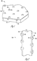
- FIG. 1 illustrates an example embodiment of such a heat sink and fin combination.
- the heat sink 100 includes a metal plate 110 that includes micro air channels 120.
- a metal foil 130 is placed on the metal plate 110.
- the metal foil 130 includes angular dimples 140 that include on their angular faces air nozzles 150.
- FIG. 2 is a side view of such a heat sink and fin combination 100, and illustrates that micro air channels can be positioned on both sides of the metal plate 110 and that a metal foil 130 can be placed on both sides of the metal plate 110.
- FIG. 3 is a side view of another embodiment that includes two layers of metal foil 130 laminated to each other, with micro air channels 120 embossed on each layer and in communication with one or more angular dimples 140 with air nozzles 150.
- the fabrication process starts by creating micro diameter holes on a metal foil using for example chemical etching, a laser, or electric discharge machining (EDM).
- the metal foil is a copper foil.
- the copper foil has high thermal conductivity and is amenable to continuous variation of the jet angle.
- Other drilling methods such as sandblasting, the use of ultrasonic waves, a water jet, or micro milling/drilling machines can be used as well.
- the EDM method is generally preferred because of better precision and uniformity.
- These holes form the micro nozzles without specified orientations.
- the holes are approximately 20 -50 micrometers in diameter.
- the nozzle orientation is created after the EDM drilling by stamping trapezoidal dimples in a mold.
- the mold is a steel mold.
- the EDM hole is placed on the slanted side walls of the dimple, creating an angle from the fin base.
- Dimple side walls are slanted from 5 to 30 degrees from the vertical (or 60 to 85 degrees from the fin surface) in different sets of molds, thus giving various jet angles (polar). This method also allows azimuth control and allows continuous variation of the jet angles.
- the metal foil that contains the micro nozzles can be laminated to a metal plate or another foil with similar micro nozzles.
- Micro-air channels for the purpose of delivering compressed air, are formed at the interface of the lamination by, for example, machining, forming, embossing, or chemical etching trenches on the metal plate or the foil, and forming enclosed channels after lamination.
- This fin fabrication process can be used to make entrainment heat sinks that have numerous application opportunities in high performance thermal management systems. Because such fins enable extremely low profile heat sinks, it is particularly suitable for space-constrained applications such as avionic systems with densely packed printed board assemblies (PBA) wherein conventional onboard fan/blowers are too bulky to fit.
- PBA printed board assemblies
- the copper foil after the dimple/nozzle formation is laminated onto a copper core which is about 0.5 mm thick and contains air channels that are in fluidic connection with the nozzle arrays.
- the fins may have nozzles on one side or both sides of the core.
- the fins can be fabricated in standard 1" x 4" format and cut into various lengths according to specific heat sink designs.
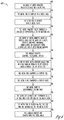
- FIGS. 4 and 5 are flowcharts of example processes 400 and 500 for forming fins for an entrainment heat sink.
- FIGS. 4 and 5 include a number of process blocks 405 - 465 and 505 - 570 respectively. Though arranged serially in the examples of FIGS. 4 and 5 , other examples may reorder the blocks, omit one or more blocks, and/or execute two or more blocks in parallel using multiple processors or a single processor organized as two or more virtual machines or sub-processors. Moreover, still other examples can implement the blocks as one or more specific interconnected hardware or integrated circuit modules with related control and data signals communicated between and through the modules. Thus, any process flow is applicable to software, firmware, hardware, and hybrid implementations.
- an array of micro diameter holes is created on a metal foil.
- the metal foil is coupled to a mold.
- the mold includes angular dimples such that one or more of the micro diameter holes on the metal foil come into contact with the angular dimples in the mold. This stamping of the metal foil with the mold forms an angle between the micro diameter holes and a surface of the metal foil.
- the metal foil is placed onto a metal plate.
- the metal plate includes micro air channels, and the micro air channels are in communication with the micro diameter holes.
- the micro diameter holes comprise a diameter of approximately 20 - 50 micrometers.
- the array of micro diameter holes is created using one or more of a laser, electric discharge machining, sandblasting, an ultrasonic wave, a water jet, and a micro milling machine.
- the angular dimples comprise trapezoidal dimples.
- the one or more micro diameter holes form an angle ranging from 60 to 85 degrees from a surface of the metal foil.
- the metal foil comprises a copper foil, at 445, the metal plate comprises a copper plate, and at 450, the metal plate is approximately 0.5 mm thick.
- the micro air channels are positioned on a top side and a bottom side of the metal plate.
- the metal foil is placed on the top side and the bottom side of the metal plate.
- the angular dimples are stamped into the mold.
- an array of micro diameter holes is created on a first metal foil
- an array of micro diameter holes is created on a second metal foil.
- the first metal foil is coupled to a mold.
- the mold includes angular dimples such that one or more holes on the first metal foil come into contact with the angular dimples in the mold. This contact forms an angle between the holes on the first metal foil and a surface of the first metal foil.
- the second metal foil is coupled to the mold such that one or more holes on the second metal foil come into contact with the angular dimples in the mold. As with the first metal foil, this contact forms an angle between the holes of the second metal foil and a surface of the second metal foil.
- micro air channels are embossed onto the first metal foil.
- the micro air channels in the first metal foil are in communication with the micro diameter holes in the first metal foil.
- micro air channels are embossed onto the second metal foil.
- the micro air channels in the second metal foil are in communication with the micro diameter holes in the second metal foil.
- the first metal foil and second metal foil are laminated together.
- the micro diameter holes of the first metal foil are in communication with the micro diameter holes of the second metal foil.
- the micro diameter holes comprise a diameter of approximately 20 - 50 micrometers.
- the array of micro diameter holes is created using one or more of a laser, electric discharge machining, sandblasting, an ultrasonic wave, a water jet, and a micro milling machine.
- the angular dimples comprise trapezoidal dimples.
- the micro diameter holes of the first metal foil and the micro diameter holes of the second metal foil form angles ranging from 60 to 85 degrees from a surface of the first meta foil and the second metal foil.
- the first metal foil and/or the second metal foil comprise a copper foil.
- the angular dimples are stamped into the steel mold.
Landscapes
- Engineering & Computer Science (AREA)
- Mechanical Engineering (AREA)
- Physics & Mathematics (AREA)
- Thermal Sciences (AREA)
- General Engineering & Computer Science (AREA)
- Aviation & Aerospace Engineering (AREA)
- Microelectronics & Electronic Packaging (AREA)
- Cooling Or The Like Of Semiconductors Or Solid State Devices (AREA)
- Cooling Or The Like Of Electrical Apparatus (AREA)
Abstract
Description
- The present disclosure relates to a fin fabrication process for an entrainment heat sink.
- In densely packed electronic systems, heat dissipation is a big challenge due to space constraints that preclude convective thermal solutions involving blowers or fans in proximity to the heat sources. For example, avionics systems with densely packed printed board assemblies (PBA), in which conventional onboard fans/blowers are too bulky to be placed, typically rely on conductive heat sinks made of solid metal plates. However, these solid metal plates are heavy and have limited performance capability.
-
-
FIG. 1 is a perspective view an example embodiment of a heat sink including fabricated fins on a metal plate. -
FIG. 2 is a side view of another example embodiment of a heat sink including fabricated fins on two sides of a metal plate. -
FIG. 3 is a side view of another example embodiment of a heat sink including two fabricated fins coupled together. -
FIG. 4 is a flowchart of an example process to manufacture a heat sink. -
FIGS. 5A and5B are a flowchart of another example process to manufacture a heat sink. - This disclosure describes a method to fabricate fins for heat sinks, and in an embodiment, entrainment heat sinks. An entrainment heat sink is driven by compressed air, can be made in extremely low-profile, and thus is able to bring convective cooling to tight spaces previously only addressable by conductive cooling methods. The fins for the entrainment heat sink differ from conventional extruded structures in that they must contain micro air flow channels and nozzles that direct air jets predominately parallel to the fin surface and in the direction of the desired bulk air flow. The micro nozzles are connected via micro air channels that facilitate compressed air delivery. In an embodiment, the micro nozzles are fabricated on a substrate such as a metal foil and may be laminated on a plate, such as a metal plate, to form a fin. Other materials that can be used alone or in combination include various metals, graphite, ceramics, polymers, and composites. The micro air channels can be formed at the interface between the metal foil and the metal plate. In another embodiment, two layers of metal foil may be laminated together. Micro air channels are embossed on each of the metal foil layers.
-
FIG. 1 illustrates an example embodiment of such a heat sink and fin combination. Theheat sink 100 includes ametal plate 110 that includesmicro air channels 120. Ametal foil 130 is placed on themetal plate 110. Themetal foil 130 includesangular dimples 140 that include on their angularfaces air nozzles 150.FIG. 2 is a side view of such a heat sink andfin combination 100, and illustrates that micro air channels can be positioned on both sides of themetal plate 110 and that ametal foil 130 can be placed on both sides of themetal plate 110.FIG. 3 is a side view of another embodiment that includes two layers ofmetal foil 130 laminated to each other, withmicro air channels 120 embossed on each layer and in communication with one or moreangular dimples 140 withair nozzles 150. - The fabrication process starts by creating micro diameter holes on a metal foil using for example chemical etching, a laser, or electric discharge machining (EDM). In an embodiment, the metal foil is a copper foil. The copper foil has high thermal conductivity and is amenable to continuous variation of the jet angle. Other drilling methods such as sandblasting, the use of ultrasonic waves, a water jet, or micro milling/drilling machines can be used as well. The EDM method is generally preferred because of better precision and uniformity. These holes form the micro nozzles without specified orientations. The holes are approximately 20 -50 micrometers in diameter. The nozzle orientation is created after the EDM drilling by stamping trapezoidal dimples in a mold. In an embodiment, the mold is a steel mold. In the stamping process the EDM hole is placed on the slanted side walls of the dimple, creating an angle from the fin base. Dimple side walls are slanted from 5 to 30 degrees from the vertical (or 60 to 85 degrees from the fin surface) in different sets of molds, thus giving various jet angles (polar). This method also allows azimuth control and allows continuous variation of the jet angles.
- The metal foil that contains the micro nozzles can be laminated to a metal plate or another foil with similar micro nozzles. Micro-air channels, for the purpose of delivering compressed air, are formed at the interface of the lamination by, for example, machining, forming, embossing, or chemical etching trenches on the metal plate or the foil, and forming enclosed channels after lamination.
- This fin fabrication process can be used to make entrainment heat sinks that have numerous application opportunities in high performance thermal management systems. Because such fins enable extremely low profile heat sinks, it is particularly suitable for space-constrained applications such as avionic systems with densely packed printed board assemblies (PBA) wherein conventional onboard fan/blowers are too bulky to fit.
- In an embodiment, the copper foil after the dimple/nozzle formation is laminated onto a copper core which is about 0.5 mm thick and contains air channels that are in fluidic connection with the nozzle arrays. The fins may have nozzles on one side or both sides of the core. The fins can be fabricated in standard 1" x 4" format and cut into various lengths according to specific heat sink designs.
-
FIGS. 4 and5 are flowcharts ofexample processes FIGS. 4 and5 include a number of process blocks 405 - 465 and 505 - 570 respectively. Though arranged serially in the examples ofFIGS. 4 and5 , other examples may reorder the blocks, omit one or more blocks, and/or execute two or more blocks in parallel using multiple processors or a single processor organized as two or more virtual machines or sub-processors. Moreover, still other examples can implement the blocks as one or more specific interconnected hardware or integrated circuit modules with related control and data signals communicated between and through the modules. Thus, any process flow is applicable to software, firmware, hardware, and hybrid implementations. - Referring to
FIG. 4 , at 405, an array of micro diameter holes is created on a metal foil. At 410, the metal foil is coupled to a mold. The mold includes angular dimples such that one or more of the micro diameter holes on the metal foil come into contact with the angular dimples in the mold. This stamping of the metal foil with the mold forms an angle between the micro diameter holes and a surface of the metal foil. At 415, the metal foil is placed onto a metal plate. The metal plate includes micro air channels, and the micro air channels are in communication with the micro diameter holes. - At 420, the micro diameter holes comprise a diameter of approximately 20 - 50 micrometers. At 425, the array of micro diameter holes is created using one or more of a laser, electric discharge machining, sandblasting, an ultrasonic wave, a water jet, and a micro milling machine. At 430, the angular dimples comprise trapezoidal dimples. At 435, the one or more micro diameter holes form an angle ranging from 60 to 85 degrees from a surface of the metal foil. At 440, the metal foil comprises a copper foil, at 445, the metal plate comprises a copper plate, and at 450, the metal plate is approximately 0.5 mm thick. At 455, the micro air channels are positioned on a top side and a bottom side of the metal plate. At 460, the metal foil is placed on the top side and the bottom side of the metal plate. At 465, the angular dimples are stamped into the mold.
- Referring to
FIG. 5 , at 505, an array of micro diameter holes is created on a first metal foil, and at 510, an array of micro diameter holes is created on a second metal foil. At 515, the first metal foil is coupled to a mold. The mold includes angular dimples such that one or more holes on the first metal foil come into contact with the angular dimples in the mold. This contact forms an angle between the holes on the first metal foil and a surface of the first metal foil. At 520, the second metal foil is coupled to the mold such that one or more holes on the second metal foil come into contact with the angular dimples in the mold. As with the first metal foil, this contact forms an angle between the holes of the second metal foil and a surface of the second metal foil. At 525, micro air channels are embossed onto the first metal foil. The micro air channels in the first metal foil are in communication with the micro diameter holes in the first metal foil. Similarly, at 530, micro air channels are embossed onto the second metal foil. The micro air channels in the second metal foil are in communication with the micro diameter holes in the second metal foil. At 535, the first metal foil and second metal foil are laminated together. - At 540, the micro diameter holes of the first metal foil are in communication with the micro diameter holes of the second metal foil. At 545, the micro diameter holes comprise a diameter of approximately 20 - 50 micrometers. At 550, the array of micro diameter holes is created using one or more of a laser, electric discharge machining, sandblasting, an ultrasonic wave, a water jet, and a micro milling machine. At 555, the angular dimples comprise trapezoidal dimples. At 560, the micro diameter holes of the first metal foil and the micro diameter holes of the second metal foil form angles ranging from 60 to 85 degrees from a surface of the first meta foil and the second metal foil. At 565, the first metal foil and/or the second metal foil comprise a copper foil. At 570, the angular dimples are stamped into the steel mold.
- It should be understood that there exist implementations of other variations and modifications of the invention and its various aspects, as may be readily apparent, for example, to those of ordinary skill in the art, and that the invention is not limited by specific embodiments described herein. Features and embodiments described above may be combined with each other in different combinations. It is therefore contemplated to cover any and all modifications, variations, combinations or equivalents that fall within the scope of the present invention.
- The Abstract is provided to comply with 37 C.F.R. § 1.72(b) and will allow the reader to quickly ascertain the nature and gist of the technical disclosure. It is submitted with the understanding that it will not be used to interpret or limit the scope or meaning of the claims.
Claims (10)
- A process comprising:creating an array of micro diameter holes on a substrate (405);coupling the substrate to a mold, the mold comprising angular dimples such that one or more of the micro diameter holes on the substrate come into contact with the angular dimples in the mold, thereby forming an angle between the micro diameter holes and a surface of the substrate; and (410)placing the substrate onto a plate, the plate comprising micro air channels such that the micro air channels are in communication with the micro diameter holes. (415)
- The process of claim 1, comprising creating the array of micro diameter holes using one or more of a laser, electric discharge machining, sandblasting, an ultrasonic wave, a water jet, chemical etching, and a micro milling machine. (425)
- The process of claim 1, wherein the angular dimples comprise trapezoidal dimples. (430)
- The process of claim 1, wherein the micro air channels are positioned on a top side and a bottom side of the plate; and comprising placing the substrate on the top side and the bottom side of the plate. (460)
- A process comprising:creating an array of micro diameter holes on a first substrate; (505)creating an array of micro diameter holes on a second substrate; (510)coupling the first substrate to a mold comprising angular dimples such that one or more holes on the first substrate come into contact with the angular dimples in the mold, thereby forming an angle between the holes on the first substrate and a surface of the first substrate; (515)coupling the second substrate to the mold comprising angular dimples such that one or more holes on the second substrate come into contact with the angular dimples in the mold, thereby forming an angle between the holes of the second substrate and a surface of the second substrate; (520)embossing micro air channels in the first substrate, wherein the micro air channels in the first substrate are in communication with the micro diameter holes in the first substrate; (525)embossing micro air channels in the second substrate, wherein the micro air channels in the second substrate are in communication with the micro diameter holes in the second substrate; and (530)coupling the first substrate to the second substrate. (535)
- The process of claim 5, wherein the micro diameter holes of the first substrate are in communication with the micro diameter holes of the second substrate. (540)
- The process of claim 5, wherein the micro diameter holes comprise a diameter of approximately 20 - 50 micrometers. (545)
- The process of claim 5, wherein the micro diameter holes of the first substrate and the micro diameter holes of the second substrate form angles ranging from 60 to 85 degrees from a surface of the first substrate and the second substrate. (560)
- An apparatus comprising:a plate (110) comprising a micro air channel (120); anda substrate (130) comprising a dimple (140), the dimple comprising a surface that is between 5 and 30 degrees from normal to the substrate, the dimple comprising a micro diameter hole on the surface;wherein the substrate is coupled to the plate such that the micro air channel is in communication with the micro diameter hole.
- An apparatus comprising:a first substrate (130) comprising a first angular dimple (140), a first micro diameter hole (150), and a first micro air channel (120), wherein the first angular dimple comprises a surface that forms an angle of between 5 and 30 degrees from a normal to the surface, wherein the first micro diameter hole is on the surface of the first angular dimple, and wherein the first micro diameter hole is in communication with the first micro air channel;a second substrate (130) comprising a second angular dimple (140), a second micro diameter hole (150), and a second micro air channel (120), wherein the second angular dimple comprises a surface that forms an angle of between 5 and 30 degrees from a normal to the surface, wherein the second micro diameter hole is on the surface of the second angular dimple, and wherein the second micro diameter hole is in communication with the second micro air channel;wherein the first substrate is laminated to the second substrate (130, 130).
Applications Claiming Priority (2)
| Application Number | Priority Date | Filing Date | Title |
|---|---|---|---|
| US12/955,449 US9111918B2 (en) | 2010-11-29 | 2010-11-29 | Fin fabrication process for entrainment heat sink |
| EP11182997.4A EP2458625B1 (en) | 2010-11-29 | 2011-09-27 | Fin fabrication process for entrainment heat sink |
Related Parent Applications (2)
| Application Number | Title | Priority Date | Filing Date |
|---|---|---|---|
| EP11182997.4A Division-Into EP2458625B1 (en) | 2010-11-29 | 2011-09-27 | Fin fabrication process for entrainment heat sink |
| EP11182997.4A Division EP2458625B1 (en) | 2010-11-29 | 2011-09-27 | Fin fabrication process for entrainment heat sink |
Publications (2)
| Publication Number | Publication Date |
|---|---|
| EP3591692A1 true EP3591692A1 (en) | 2020-01-08 |
| EP3591692B1 EP3591692B1 (en) | 2024-09-25 |
Family
ID=44720707
Family Applications (2)
| Application Number | Title | Priority Date | Filing Date |
|---|---|---|---|
| EP19191529.7A Active EP3591692B1 (en) | 2010-11-29 | 2011-09-27 | Fin fabrication process for entrainment heat sink |
| EP11182997.4A Active EP2458625B1 (en) | 2010-11-29 | 2011-09-27 | Fin fabrication process for entrainment heat sink |
Family Applications After (1)
| Application Number | Title | Priority Date | Filing Date |
|---|---|---|---|
| EP11182997.4A Active EP2458625B1 (en) | 2010-11-29 | 2011-09-27 | Fin fabrication process for entrainment heat sink |
Country Status (2)
| Country | Link |
|---|---|
| US (1) | US9111918B2 (en) |
| EP (2) | EP3591692B1 (en) |
Families Citing this family (3)
| Publication number | Priority date | Publication date | Assignee | Title |
|---|---|---|---|---|
| US9277679B2 (en) | 2010-11-29 | 2016-03-01 | Honeywell International Inc. | Heat sink fin including angular dimples |
| US9665138B2 (en) | 2014-04-07 | 2017-05-30 | Microsoft Technology Licensing, Llc | Micro-hole vents for device ventilation systems |
| CN112432086B (en) * | 2020-11-25 | 2022-06-17 | 浙江北光科技股份有限公司 | LED (light-emitting diode) down lamp |
Citations (3)
| Publication number | Priority date | Publication date | Assignee | Title |
|---|---|---|---|---|
| US6131646A (en) * | 1998-01-19 | 2000-10-17 | Trw Inc. | Heat conductive interface material |
| US20090290305A1 (en) * | 2008-05-20 | 2009-11-26 | Wei Yang | Entrainment heatsink using engine bleed air |
| US20090288807A1 (en) * | 2008-05-20 | 2009-11-26 | Honeywell International Inc. | Blowerless heat exchanger based on micro-jet entrainment |
Family Cites Families (25)
| Publication number | Priority date | Publication date | Assignee | Title |
|---|---|---|---|---|
| US4417295A (en) | 1977-06-30 | 1983-11-22 | International Business Machines Corporation | Air jet powered cooling system for electronic assemblies |
| US4296455A (en) | 1979-11-23 | 1981-10-20 | International Business Machines Corporation | Slotted heat sinks for high powered air cooled modules |
| US4800956A (en) | 1986-04-25 | 1989-01-31 | Digital Equipment Corporation | Apparatus and method for removal of heat from packaged element |
| US4851965A (en) | 1987-03-09 | 1989-07-25 | Unisys Corporation | Directed air management system for cooling multiple heat sinks |
| JP2934493B2 (en) | 1990-10-24 | 1999-08-16 | 株式会社日立製作所 | Electronic equipment cooling device |
| JP3405997B2 (en) * | 1991-10-23 | 2003-05-12 | 株式会社デンソー | Inner fin and manufacturing method thereof |
| US5428503A (en) | 1992-03-24 | 1995-06-27 | Hitachi, Ltd. | Jet cooling apparatus for cooling electronic equipment and computer having the same mounted thereon |
| US6352103B1 (en) | 1996-05-22 | 2002-03-05 | Intel Corporation | High performance notebook PC cooling system |
| US5731954A (en) | 1996-08-22 | 1998-03-24 | Cheon; Kioan | Cooling system for computer |
| US6373696B1 (en) | 1998-06-15 | 2002-04-16 | Compaq Computer Corporation | Hard drive cooling using finned heat sink and thermally conductive interface pad |
| US6378605B1 (en) | 1999-12-02 | 2002-04-30 | Midwest Research Institute | Heat exchanger with transpired, highly porous fins |
| US6538885B1 (en) | 2000-09-15 | 2003-03-25 | Lucent Technologies Inc. | Electronic circuit cooling with impingement plate |
| US6427466B1 (en) | 2000-12-12 | 2002-08-06 | Celletra Ltd | Forced convection cooling system for electronic equipment |
| WO2002052912A1 (en) | 2000-12-23 | 2002-07-04 | Korea Advanced Institute Of Science & Technology | Heat sink |
| DE50207354D1 (en) * | 2001-04-28 | 2006-08-10 | Behr Gmbh & Co Kg | Folded multi-chamber flat tube |
| US20020166654A1 (en) | 2001-05-02 | 2002-11-14 | Smalc Martin D. | Finned Heat Sink Assemblies |
| US6538892B2 (en) | 2001-05-02 | 2003-03-25 | Graftech Inc. | Radial finned heat sink |
| US6827130B2 (en) | 2001-06-05 | 2004-12-07 | Heat Technology, Inc. | Heatsink assembly and method of manufacturing the same |
| US6587336B2 (en) | 2001-06-27 | 2003-07-01 | International Business Machines Corporation | Cooling system for portable electronic and computer devices |
| US6817405B2 (en) | 2002-06-03 | 2004-11-16 | International Business Machines Corporation | Apparatus having forced fluid cooling and pin-fin heat sink |
| US6918438B2 (en) | 2002-06-04 | 2005-07-19 | International Business Machines Corporation | Finned heat sink |
| US6622519B1 (en) | 2002-08-15 | 2003-09-23 | Velocys, Inc. | Process for cooling a product in a heat exchanger employing microchannels for the flow of refrigerant and product |
| US6765796B2 (en) | 2002-11-21 | 2004-07-20 | Teradyne, Inc. | Circuit board cover with exhaust apertures for cooling electronic components |
| US6781834B2 (en) | 2003-01-24 | 2004-08-24 | Hewlett-Packard Development Company, L.P. | Cooling device with air shower |
| US9277679B2 (en) | 2010-11-29 | 2016-03-01 | Honeywell International Inc. | Heat sink fin including angular dimples |
-
2010
- 2010-11-29 US US12/955,449 patent/US9111918B2/en active Active
-
2011
- 2011-09-27 EP EP19191529.7A patent/EP3591692B1/en active Active
- 2011-09-27 EP EP11182997.4A patent/EP2458625B1/en active Active
Patent Citations (3)
| Publication number | Priority date | Publication date | Assignee | Title |
|---|---|---|---|---|
| US6131646A (en) * | 1998-01-19 | 2000-10-17 | Trw Inc. | Heat conductive interface material |
| US20090290305A1 (en) * | 2008-05-20 | 2009-11-26 | Wei Yang | Entrainment heatsink using engine bleed air |
| US20090288807A1 (en) * | 2008-05-20 | 2009-11-26 | Honeywell International Inc. | Blowerless heat exchanger based on micro-jet entrainment |
Also Published As
| Publication number | Publication date |
|---|---|
| EP2458625B1 (en) | 2019-11-06 |
| EP2458625A2 (en) | 2012-05-30 |
| US9111918B2 (en) | 2015-08-18 |
| US20120131979A1 (en) | 2012-05-31 |
| EP3591692B1 (en) | 2024-09-25 |
| EP2458625A3 (en) | 2017-12-27 |
Similar Documents
| Publication | Publication Date | Title |
|---|---|---|
| US9277679B2 (en) | Heat sink fin including angular dimples | |
| TWI720071B (en) | Electronic apparatus, method for cooling electronic device and computing system | |
| JP5057221B2 (en) | Metal base printed circuit board with heat radiating portion and manufacturing method thereof | |
| US20030221814A1 (en) | Apparatus having forced fluid cooling and pin-fin heat sink | |
| WO2013062131A1 (en) | Flow channel member, heat exchanger using same, semiconductor device, and device for manufacturing semiconductor | |
| EP3465064B1 (en) | Cooling device with evenly distributed and directed cooling effect for high heat flux and deaeration functionality | |
| EP3591692B1 (en) | Fin fabrication process for entrainment heat sink | |
| CN103957682B (en) | Heat abstractor and there is the electronic equipment of this heat abstractor | |
| CN107734840A (en) | Based on the cold cooling structure of printed circuit board three-dimensional micro-channel array liquid | |
| US20160095197A1 (en) | Circuit board module and circuit board structure | |
| JP5435428B2 (en) | Radiator with foil-like radiating fin and method for forming the same | |
| JP2013219127A (en) | Heat exchanger | |
| CN109950215B (en) | A microchannel cold plate with bubbling partition and electronic equipment | |
| CN212367779U (en) | Radiator and radiating fin thereof | |
| US8857501B2 (en) | Entrainment heat sink devices | |
| JP2011171686A (en) | Metal-based printed board with heat radiation part | |
| CN103391702B (en) | Heat sink and manufacturing method thereof | |
| CN113301777B (en) | Vapor chamber, method for manufacturing vapor chamber, and electronic apparatus | |
| CN207427569U (en) | One kind is based on the cold cooling structure of printed circuit board three-dimensional micro-channel array liquid | |
| JP6437844B2 (en) | Channel member, heat exchanger using the same, and semiconductor manufacturing apparatus | |
| JP2014207420A (en) | Method of manufacturing radiator | |
| CN212751993U (en) | Heat dissipation mechanism of permanent magnet coupler | |
| CN220108552U (en) | Fin type radiator | |
| CN102647891A (en) | Air cooling radiator | |
| CN210432015U (en) | PCB board with heat dissipation function |
Legal Events
| Date | Code | Title | Description |
|---|---|---|---|
| PUAI | Public reference made under article 153(3) epc to a published international application that has entered the european phase |
Free format text: ORIGINAL CODE: 0009012 |
|
| STAA | Information on the status of an ep patent application or granted ep patent |
Free format text: STATUS: REQUEST FOR EXAMINATION WAS MADE |
|
| 17P | Request for examination filed |
Effective date: 20190813 |
|
| AC | Divisional application: reference to earlier application |
Ref document number: 2458625 Country of ref document: EP Kind code of ref document: P |
|
| AK | Designated contracting states |
Kind code of ref document: A1 Designated state(s): AL AT BE BG CH CY CZ DE DK EE ES FI FR GB GR HR HU IE IS IT LI LT LU LV MC MK MT NL NO PL PT RO RS SE SI SK SM TR |
|
| STAA | Information on the status of an ep patent application or granted ep patent |
Free format text: STATUS: EXAMINATION IS IN PROGRESS |
|
| 17Q | First examination report despatched |
Effective date: 20211213 |
|
| P01 | Opt-out of the competence of the unified patent court (upc) registered |
Effective date: 20230421 |
|
| RIC1 | Information provided on ipc code assigned before grant |
Ipc: F28F 3/04 20060101ALN20240301BHEP Ipc: F28F 3/12 20060101ALN20240301BHEP Ipc: H05K 7/20 20060101ALI20240301BHEP Ipc: H01L 21/48 20060101AFI20240301BHEP |
|
| GRAP | Despatch of communication of intention to grant a patent |
Free format text: ORIGINAL CODE: EPIDOSNIGR1 |
|
| STAA | Information on the status of an ep patent application or granted ep patent |
Free format text: STATUS: GRANT OF PATENT IS INTENDED |
|
| INTG | Intention to grant announced |
Effective date: 20240418 |
|
| GRAS | Grant fee paid |
Free format text: ORIGINAL CODE: EPIDOSNIGR3 |
|
| GRAA | (expected) grant |
Free format text: ORIGINAL CODE: 0009210 |
|
| STAA | Information on the status of an ep patent application or granted ep patent |
Free format text: STATUS: THE PATENT HAS BEEN GRANTED |
|
| AC | Divisional application: reference to earlier application |
Ref document number: 2458625 Country of ref document: EP Kind code of ref document: P |
|
| AK | Designated contracting states |
Kind code of ref document: B1 Designated state(s): AL AT BE BG CH CY CZ DE DK EE ES FI FR GB GR HR HU IE IS IT LI LT LU LV MC MK MT NL NO PL PT RO RS SE SI SK SM TR |
|
| REG | Reference to a national code |
Ref country code: GB Ref legal event code: FG4D |
|
| REG | Reference to a national code |
Ref country code: CH Ref legal event code: EP |
|
| REG | Reference to a national code |
Ref country code: DE Ref legal event code: R096 Ref document number: 602011075007 Country of ref document: DE |
|
| REG | Reference to a national code |
Ref country code: IE Ref legal event code: FG4D |
|
| REG | Reference to a national code |
Ref country code: LT Ref legal event code: MG9D |
|
| PG25 | Lapsed in a contracting state [announced via postgrant information from national office to epo] |
Ref country code: NO Free format text: LAPSE BECAUSE OF FAILURE TO SUBMIT A TRANSLATION OF THE DESCRIPTION OR TO PAY THE FEE WITHIN THE PRESCRIBED TIME-LIMIT Effective date: 20241225 |
|
| PG25 | Lapsed in a contracting state [announced via postgrant information from national office to epo] |
Ref country code: GR Free format text: LAPSE BECAUSE OF FAILURE TO SUBMIT A TRANSLATION OF THE DESCRIPTION OR TO PAY THE FEE WITHIN THE PRESCRIBED TIME-LIMIT Effective date: 20241226 Ref country code: FI Free format text: LAPSE BECAUSE OF FAILURE TO SUBMIT A TRANSLATION OF THE DESCRIPTION OR TO PAY THE FEE WITHIN THE PRESCRIBED TIME-LIMIT Effective date: 20240925 |
|
| PG25 | Lapsed in a contracting state [announced via postgrant information from national office to epo] |
Ref country code: BG Free format text: LAPSE BECAUSE OF FAILURE TO SUBMIT A TRANSLATION OF THE DESCRIPTION OR TO PAY THE FEE WITHIN THE PRESCRIBED TIME-LIMIT Effective date: 20240925 |
|
| PG25 | Lapsed in a contracting state [announced via postgrant information from national office to epo] |
Ref country code: LV Free format text: LAPSE BECAUSE OF FAILURE TO SUBMIT A TRANSLATION OF THE DESCRIPTION OR TO PAY THE FEE WITHIN THE PRESCRIBED TIME-LIMIT Effective date: 20240925 |
|
| PG25 | Lapsed in a contracting state [announced via postgrant information from national office to epo] |
Ref country code: RS Free format text: LAPSE BECAUSE OF FAILURE TO SUBMIT A TRANSLATION OF THE DESCRIPTION OR TO PAY THE FEE WITHIN THE PRESCRIBED TIME-LIMIT Effective date: 20241225 |
|
| REG | Reference to a national code |
Ref country code: NL Ref legal event code: MP Effective date: 20240925 |
|
| PG25 | Lapsed in a contracting state [announced via postgrant information from national office to epo] |
Ref country code: RS Free format text: LAPSE BECAUSE OF FAILURE TO SUBMIT A TRANSLATION OF THE DESCRIPTION OR TO PAY THE FEE WITHIN THE PRESCRIBED TIME-LIMIT Effective date: 20241225 Ref country code: NO Free format text: LAPSE BECAUSE OF FAILURE TO SUBMIT A TRANSLATION OF THE DESCRIPTION OR TO PAY THE FEE WITHIN THE PRESCRIBED TIME-LIMIT Effective date: 20241225 Ref country code: LV Free format text: LAPSE BECAUSE OF FAILURE TO SUBMIT A TRANSLATION OF THE DESCRIPTION OR TO PAY THE FEE WITHIN THE PRESCRIBED TIME-LIMIT Effective date: 20240925 Ref country code: GR Free format text: LAPSE BECAUSE OF FAILURE TO SUBMIT A TRANSLATION OF THE DESCRIPTION OR TO PAY THE FEE WITHIN THE PRESCRIBED TIME-LIMIT Effective date: 20241226 Ref country code: FI Free format text: LAPSE BECAUSE OF FAILURE TO SUBMIT A TRANSLATION OF THE DESCRIPTION OR TO PAY THE FEE WITHIN THE PRESCRIBED TIME-LIMIT Effective date: 20240925 Ref country code: BG Free format text: LAPSE BECAUSE OF FAILURE TO SUBMIT A TRANSLATION OF THE DESCRIPTION OR TO PAY THE FEE WITHIN THE PRESCRIBED TIME-LIMIT Effective date: 20240925 |
|
| REG | Reference to a national code |
Ref country code: AT Ref legal event code: MK05 Ref document number: 1727407 Country of ref document: AT Kind code of ref document: T Effective date: 20240925 |
|
| PG25 | Lapsed in a contracting state [announced via postgrant information from national office to epo] |
Ref country code: NL Free format text: LAPSE BECAUSE OF FAILURE TO SUBMIT A TRANSLATION OF THE DESCRIPTION OR TO PAY THE FEE WITHIN THE PRESCRIBED TIME-LIMIT Effective date: 20240925 |
|
| REG | Reference to a national code |
Ref country code: DE Ref legal event code: R119 Ref document number: 602011075007 Country of ref document: DE |
|
| PG25 | Lapsed in a contracting state [announced via postgrant information from national office to epo] |
Ref country code: PT Free format text: LAPSE BECAUSE OF FAILURE TO SUBMIT A TRANSLATION OF THE DESCRIPTION OR TO PAY THE FEE WITHIN THE PRESCRIBED TIME-LIMIT Effective date: 20250127 Ref country code: IS Free format text: LAPSE BECAUSE OF FAILURE TO SUBMIT A TRANSLATION OF THE DESCRIPTION OR TO PAY THE FEE WITHIN THE PRESCRIBED TIME-LIMIT Effective date: 20250125 |
|
| PG25 | Lapsed in a contracting state [announced via postgrant information from national office to epo] |
Ref country code: RO Free format text: LAPSE BECAUSE OF FAILURE TO SUBMIT A TRANSLATION OF THE DESCRIPTION OR TO PAY THE FEE WITHIN THE PRESCRIBED TIME-LIMIT Effective date: 20240925 Ref country code: SM Free format text: LAPSE BECAUSE OF FAILURE TO SUBMIT A TRANSLATION OF THE DESCRIPTION OR TO PAY THE FEE WITHIN THE PRESCRIBED TIME-LIMIT Effective date: 20240925 |
|
| PG25 | Lapsed in a contracting state [announced via postgrant information from national office to epo] |
Ref country code: ES Free format text: LAPSE BECAUSE OF FAILURE TO SUBMIT A TRANSLATION OF THE DESCRIPTION OR TO PAY THE FEE WITHIN THE PRESCRIBED TIME-LIMIT Effective date: 20240925 |
|
| PG25 | Lapsed in a contracting state [announced via postgrant information from national office to epo] |
Ref country code: EE Free format text: LAPSE BECAUSE OF FAILURE TO SUBMIT A TRANSLATION OF THE DESCRIPTION OR TO PAY THE FEE WITHIN THE PRESCRIBED TIME-LIMIT Effective date: 20240925 Ref country code: AT Free format text: LAPSE BECAUSE OF FAILURE TO SUBMIT A TRANSLATION OF THE DESCRIPTION OR TO PAY THE FEE WITHIN THE PRESCRIBED TIME-LIMIT Effective date: 20240925 |
|
| PG25 | Lapsed in a contracting state [announced via postgrant information from national office to epo] |
Ref country code: PL Free format text: LAPSE BECAUSE OF FAILURE TO SUBMIT A TRANSLATION OF THE DESCRIPTION OR TO PAY THE FEE WITHIN THE PRESCRIBED TIME-LIMIT Effective date: 20240925 Ref country code: CZ Free format text: LAPSE BECAUSE OF FAILURE TO SUBMIT A TRANSLATION OF THE DESCRIPTION OR TO PAY THE FEE WITHIN THE PRESCRIBED TIME-LIMIT Effective date: 20240925 |
|
| PG25 | Lapsed in a contracting state [announced via postgrant information from national office to epo] |
Ref country code: SK Free format text: LAPSE BECAUSE OF FAILURE TO SUBMIT A TRANSLATION OF THE DESCRIPTION OR TO PAY THE FEE WITHIN THE PRESCRIBED TIME-LIMIT Effective date: 20240925 Ref country code: IT Free format text: LAPSE BECAUSE OF FAILURE TO SUBMIT A TRANSLATION OF THE DESCRIPTION OR TO PAY THE FEE WITHIN THE PRESCRIBED TIME-LIMIT Effective date: 20240925 |
|
| REG | Reference to a national code |
Ref country code: CH Ref legal event code: PL |
|
| PG25 | Lapsed in a contracting state [announced via postgrant information from national office to epo] |
Ref country code: LU Free format text: LAPSE BECAUSE OF NON-PAYMENT OF DUE FEES Effective date: 20240927 |
|
| PG25 | Lapsed in a contracting state [announced via postgrant information from national office to epo] |
Ref country code: MC Free format text: LAPSE BECAUSE OF FAILURE TO SUBMIT A TRANSLATION OF THE DESCRIPTION OR TO PAY THE FEE WITHIN THE PRESCRIBED TIME-LIMIT Effective date: 20240925 |
|
| PG25 | Lapsed in a contracting state [announced via postgrant information from national office to epo] |
Ref country code: DE Free format text: LAPSE BECAUSE OF NON-PAYMENT OF DUE FEES Effective date: 20250401 |
|
| PG25 | Lapsed in a contracting state [announced via postgrant information from national office to epo] |
Ref country code: DK Free format text: LAPSE BECAUSE OF FAILURE TO SUBMIT A TRANSLATION OF THE DESCRIPTION OR TO PAY THE FEE WITHIN THE PRESCRIBED TIME-LIMIT Effective date: 20240925 |
|
| REG | Reference to a national code |
Ref country code: BE Ref legal event code: MM Effective date: 20240930 |
|
| PG25 | Lapsed in a contracting state [announced via postgrant information from national office to epo] |
Ref country code: BE Free format text: LAPSE BECAUSE OF NON-PAYMENT OF DUE FEES Effective date: 20240930 |
|
| PG25 | Lapsed in a contracting state [announced via postgrant information from national office to epo] |
Ref country code: CH Free format text: LAPSE BECAUSE OF NON-PAYMENT OF DUE FEES Effective date: 20240930 |
|
| PG25 | Lapsed in a contracting state [announced via postgrant information from national office to epo] |
Ref country code: IE Free format text: LAPSE BECAUSE OF NON-PAYMENT OF DUE FEES Effective date: 20240927 |
|
| PLBE | No opposition filed within time limit |
Free format text: ORIGINAL CODE: 0009261 |
|
| STAA | Information on the status of an ep patent application or granted ep patent |
Free format text: STATUS: NO OPPOSITION FILED WITHIN TIME LIMIT |
|
| GBPC | Gb: european patent ceased through non-payment of renewal fee |
Effective date: 20241225 |
|
| 26N | No opposition filed |
Effective date: 20250626 |
|
| PG25 | Lapsed in a contracting state [announced via postgrant information from national office to epo] |
Ref country code: SE Free format text: LAPSE BECAUSE OF FAILURE TO SUBMIT A TRANSLATION OF THE DESCRIPTION OR TO PAY THE FEE WITHIN THE PRESCRIBED TIME-LIMIT Effective date: 20240925 |
|
| PG25 | Lapsed in a contracting state [announced via postgrant information from national office to epo] |
Ref country code: GB Free format text: LAPSE BECAUSE OF NON-PAYMENT OF DUE FEES Effective date: 20241225 |
|
| PG25 | Lapsed in a contracting state [announced via postgrant information from national office to epo] |
Ref country code: FR Free format text: LAPSE BECAUSE OF NON-PAYMENT OF DUE FEES Effective date: 20241125 |
|
| PG25 | Lapsed in a contracting state [announced via postgrant information from national office to epo] |
Ref country code: HR Free format text: LAPSE BECAUSE OF FAILURE TO SUBMIT A TRANSLATION OF THE DESCRIPTION OR TO PAY THE FEE WITHIN THE PRESCRIBED TIME-LIMIT Effective date: 20240925 |
|
| PG25 | Lapsed in a contracting state [announced via postgrant information from national office to epo] |
Ref country code: CY Free format text: LAPSE BECAUSE OF FAILURE TO SUBMIT A TRANSLATION OF THE DESCRIPTION OR TO PAY THE FEE WITHIN THE PRESCRIBED TIME-LIMIT; INVALID AB INITIO Effective date: 20110927 |
|
| PG25 | Lapsed in a contracting state [announced via postgrant information from national office to epo] |
Ref country code: HU Free format text: LAPSE BECAUSE OF FAILURE TO SUBMIT A TRANSLATION OF THE DESCRIPTION OR TO PAY THE FEE WITHIN THE PRESCRIBED TIME-LIMIT; INVALID AB INITIO Effective date: 20110927 |