EP3591567A1 - Capteur optoélectronique et procédé de détection optique répétitive d'objets à distance de l'objet différente - Google Patents
Capteur optoélectronique et procédé de détection optique répétitive d'objets à distance de l'objet différente Download PDFInfo
- Publication number
- EP3591567A1 EP3591567A1 EP18181130.8A EP18181130A EP3591567A1 EP 3591567 A1 EP3591567 A1 EP 3591567A1 EP 18181130 A EP18181130 A EP 18181130A EP 3591567 A1 EP3591567 A1 EP 3591567A1
- Authority
- EP
- European Patent Office
- Prior art keywords
- sensor
- distribution
- distance
- code
- measured variable
- Prior art date
- Legal status (The legal status is an assumption and is not a legal conclusion. Google has not performed a legal analysis and makes no representation as to the accuracy of the status listed.)
- Granted
Links
- 238000001514 detection method Methods 0.000 title claims abstract description 23
- 230000005693 optoelectronics Effects 0.000 title claims abstract description 9
- 238000000034 method Methods 0.000 title claims description 16
- 230000003287 optical effect Effects 0.000 title claims description 15
- 238000009826 distribution Methods 0.000 claims abstract description 83
- 238000011156 evaluation Methods 0.000 claims abstract description 30
- 238000005259 measurement Methods 0.000 claims description 26
- 230000008859 change Effects 0.000 claims description 13
- 238000005457 optimization Methods 0.000 description 16
- 230000006978 adaptation Effects 0.000 description 5
- 230000008569 process Effects 0.000 description 5
- 238000012545 processing Methods 0.000 description 5
- 238000012423 maintenance Methods 0.000 description 4
- 230000003321 amplification Effects 0.000 description 3
- 238000004458 analytical method Methods 0.000 description 3
- 230000008901 benefit Effects 0.000 description 3
- 238000005286 illumination Methods 0.000 description 3
- 238000012544 monitoring process Methods 0.000 description 3
- 238000003199 nucleic acid amplification method Methods 0.000 description 3
- 238000006243 chemical reaction Methods 0.000 description 2
- 230000001419 dependent effect Effects 0.000 description 2
- 230000005484 gravity Effects 0.000 description 2
- 238000012015 optical character recognition Methods 0.000 description 2
- 238000001454 recorded image Methods 0.000 description 2
- 238000010972 statistical evaluation Methods 0.000 description 2
- 238000009827 uniform distribution Methods 0.000 description 2
- 235000004522 Pentaglottis sempervirens Nutrition 0.000 description 1
- 230000032683 aging Effects 0.000 description 1
- 230000005540 biological transmission Effects 0.000 description 1
- 238000004140 cleaning Methods 0.000 description 1
- 230000003247 decreasing effect Effects 0.000 description 1
- 230000006866 deterioration Effects 0.000 description 1
- 230000004069 differentiation Effects 0.000 description 1
- 230000007613 environmental effect Effects 0.000 description 1
- 230000004313 glare Effects 0.000 description 1
- 230000001771 impaired effect Effects 0.000 description 1
- 238000009434 installation Methods 0.000 description 1
- 239000011159 matrix material Substances 0.000 description 1
- 230000007246 mechanism Effects 0.000 description 1
- 238000012986 modification Methods 0.000 description 1
- 230000004048 modification Effects 0.000 description 1
- 230000036961 partial effect Effects 0.000 description 1
- 230000010363 phase shift Effects 0.000 description 1
- 238000003672 processing method Methods 0.000 description 1
- 238000003908 quality control method Methods 0.000 description 1
- 238000002310 reflectometry Methods 0.000 description 1
- 230000002441 reversible effect Effects 0.000 description 1
- 230000001932 seasonal effect Effects 0.000 description 1
- 230000035939 shock Effects 0.000 description 1
- 239000000758 substrate Substances 0.000 description 1
- 230000002123 temporal effect Effects 0.000 description 1
- 230000036962 time dependent Effects 0.000 description 1
- 238000002366 time-of-flight method Methods 0.000 description 1
Images

Classifications
-
- G—PHYSICS
- G06—COMPUTING; CALCULATING OR COUNTING
- G06K—GRAPHICAL DATA READING; PRESENTATION OF DATA; RECORD CARRIERS; HANDLING RECORD CARRIERS
- G06K7/00—Methods or arrangements for sensing record carriers, e.g. for reading patterns
- G06K7/10—Methods or arrangements for sensing record carriers, e.g. for reading patterns by electromagnetic radiation, e.g. optical sensing; by corpuscular radiation
- G06K7/10544—Methods or arrangements for sensing record carriers, e.g. for reading patterns by electromagnetic radiation, e.g. optical sensing; by corpuscular radiation by scanning of the records by radiation in the optical part of the electromagnetic spectrum
- G06K7/10712—Fixed beam scanning
- G06K7/10722—Photodetector array or CCD scanning
-
- G—PHYSICS
- G06—COMPUTING; CALCULATING OR COUNTING
- G06K—GRAPHICAL DATA READING; PRESENTATION OF DATA; RECORD CARRIERS; HANDLING RECORD CARRIERS
- G06K7/00—Methods or arrangements for sensing record carriers, e.g. for reading patterns
- G06K7/10—Methods or arrangements for sensing record carriers, e.g. for reading patterns by electromagnetic radiation, e.g. optical sensing; by corpuscular radiation
- G06K7/10009—Methods or arrangements for sensing record carriers, e.g. for reading patterns by electromagnetic radiation, e.g. optical sensing; by corpuscular radiation sensing by radiation using wavelengths larger than 0.1 mm, e.g. radio-waves or microwaves
- G06K7/10366—Methods or arrangements for sensing record carriers, e.g. for reading patterns by electromagnetic radiation, e.g. optical sensing; by corpuscular radiation sensing by radiation using wavelengths larger than 0.1 mm, e.g. radio-waves or microwaves the interrogation device being adapted for miscellaneous applications
- G06K7/10415—Methods or arrangements for sensing record carriers, e.g. for reading patterns by electromagnetic radiation, e.g. optical sensing; by corpuscular radiation sensing by radiation using wavelengths larger than 0.1 mm, e.g. radio-waves or microwaves the interrogation device being adapted for miscellaneous applications the interrogation device being fixed in its position, such as an access control device for reading wireless access cards, or a wireless ATM
- G06K7/10425—Methods or arrangements for sensing record carriers, e.g. for reading patterns by electromagnetic radiation, e.g. optical sensing; by corpuscular radiation sensing by radiation using wavelengths larger than 0.1 mm, e.g. radio-waves or microwaves the interrogation device being adapted for miscellaneous applications the interrogation device being fixed in its position, such as an access control device for reading wireless access cards, or a wireless ATM the interrogation device being arranged for interrogation of record carriers passing by the interrogation device
- G06K7/10435—Methods or arrangements for sensing record carriers, e.g. for reading patterns by electromagnetic radiation, e.g. optical sensing; by corpuscular radiation sensing by radiation using wavelengths larger than 0.1 mm, e.g. radio-waves or microwaves the interrogation device being adapted for miscellaneous applications the interrogation device being fixed in its position, such as an access control device for reading wireless access cards, or a wireless ATM the interrogation device being arranged for interrogation of record carriers passing by the interrogation device the interrogation device being positioned close to a conveyor belt or the like on which moving record carriers are passing
-
- G—PHYSICS
- G06—COMPUTING; CALCULATING OR COUNTING
- G06K—GRAPHICAL DATA READING; PRESENTATION OF DATA; RECORD CARRIERS; HANDLING RECORD CARRIERS
- G06K7/00—Methods or arrangements for sensing record carriers, e.g. for reading patterns
- G06K7/10—Methods or arrangements for sensing record carriers, e.g. for reading patterns by electromagnetic radiation, e.g. optical sensing; by corpuscular radiation
- G06K7/10544—Methods or arrangements for sensing record carriers, e.g. for reading patterns by electromagnetic radiation, e.g. optical sensing; by corpuscular radiation by scanning of the records by radiation in the optical part of the electromagnetic spectrum
- G06K7/10792—Special measures in relation to the object to be scanned
- G06K7/10801—Multidistance reading
-
- G—PHYSICS
- G06—COMPUTING; CALCULATING OR COUNTING
- G06K—GRAPHICAL DATA READING; PRESENTATION OF DATA; RECORD CARRIERS; HANDLING RECORD CARRIERS
- G06K7/00—Methods or arrangements for sensing record carriers, e.g. for reading patterns
- G06K7/10—Methods or arrangements for sensing record carriers, e.g. for reading patterns by electromagnetic radiation, e.g. optical sensing; by corpuscular radiation
- G06K7/10544—Methods or arrangements for sensing record carriers, e.g. for reading patterns by electromagnetic radiation, e.g. optical sensing; by corpuscular radiation by scanning of the records by radiation in the optical part of the electromagnetic spectrum
- G06K7/10821—Methods or arrangements for sensing record carriers, e.g. for reading patterns by electromagnetic radiation, e.g. optical sensing; by corpuscular radiation by scanning of the records by radiation in the optical part of the electromagnetic spectrum further details of bar or optical code scanning devices
- G06K7/10851—Circuits for pulse shaping, amplifying, eliminating noise signals, checking the function of the sensing device
-
- G—PHYSICS
- G06—COMPUTING; CALCULATING OR COUNTING
- G06K—GRAPHICAL DATA READING; PRESENTATION OF DATA; RECORD CARRIERS; HANDLING RECORD CARRIERS
- G06K7/00—Methods or arrangements for sensing record carriers, e.g. for reading patterns
- G06K7/10—Methods or arrangements for sensing record carriers, e.g. for reading patterns by electromagnetic radiation, e.g. optical sensing; by corpuscular radiation
- G06K7/14—Methods or arrangements for sensing record carriers, e.g. for reading patterns by electromagnetic radiation, e.g. optical sensing; by corpuscular radiation using light without selection of wavelength, e.g. sensing reflected white light
- G06K7/1404—Methods for optical code recognition
- G06K7/146—Methods for optical code recognition the method including quality enhancement steps
Definitions
- the invention relates to an optoelectronic sensor and a method for the repeated optical detection of objects at different object distances according to the preamble of claims 1 and 15, respectively.
- cameras are used in a variety of ways to automatically detect object properties, for example for inspecting or measuring objects. Images of the object are recorded and evaluated according to the task by image processing methods. Another application of cameras is reading codes. With the help of an image sensor, objects are recorded with the codes on them, the code areas are identified in the images and then decoded. Camera-based code readers can easily cope with code types other than one-dimensional bar codes, which like a matrix code are also two-dimensional and provide more information.
- OCR Optical Character Recognition
- handwriting is basically a reading of codes. Typical areas of application for code readers are supermarket checkouts, automatic parcel identification, sorting of mail items, baggage handling in airports and other logistics applications. In addition to the camera-based code readers, the barcode scanners that have been known for some time are still widely used.
- a common detection situation is mounting the camera on a conveyor belt.
- the camera records images during the relative movement of the object stream on the conveyor belt and initiates further processing steps depending on the object properties obtained.
- processing steps are, for example, in further processing adapted to the specific object on a machine that acts on the objects being conveyed, or in a change in the object stream, in that certain objects are removed from the object stream as part of a quality control or the object stream is sorted into several partial object streams.
- the objects for correct sorting or similar processing steps are identified on the basis of the codes attached.
- the camera is mounted and aligned at a suitable position for commissioning, for which it often also offers assistance such as projected target patterns and the like. It is then regularly assumed that the camera is optimally installed and that the state of the camera does not change in relation to the environment over a certain runtime. However, this assumption is not always justified. Conventional cameras and barcode scanners also have practically no intrinsic intelligence in order to exploit the optimization potential.
- the EP 0 789 315 B1 discloses a code reader with a control for their decoding behavior in order to find and maintain an optimal compromise between performance and reliability. This refers to parameters of the decoder and not the actual optical detection, the changes of which are accepted as an external influence and which the control tries to compensate. No object distances are measured or other additional optical information is obtained to improve the control.
- a light receiver detects reception light from the objects and generates a reception signal therefrom.
- this is preferably image data.
- An evaluation unit obtains at least object information from the received signal. The respective object distance is also measured.
- a separate distance sensor is preferably used, which is based in particular on a time of flight (TOF) method and works in parallel or in the background for the actual measurement of the object information. It is conceivable that the light receiver or its received signal is involved in or carries out this distance measurement. Even then, however, the measurement of the object distance is an additional evaluation and / or measurement and the object distance is further information in addition to the object information.
- TOF time of flight
- the invention is based on the basic idea of monitoring the state of the sensor by means of the distance measurement and making statistical statements as to whether there is optimization potential or need for maintenance. This monitoring takes place in parallel to the actual operation in which the object information is generated.
- a measured variable is obtained from the received signal and assigned to the object distance, whereby, for example, temporal proximity ensures that the measured variable and object distance belong to the same object.
- the measured variable is not the object information, but rather an auxiliary variable, for example the value characterizing the acquisition of the actual object information, such as contrast, exposure or a success assessment.
- the distribution always refers to a certain period of time and thus a large number of objects detected.
- the choice of this large number should be such that sufficient statistics are available, but at the same time the respective period is short enough to react to external changes after an appropriate changeover time, which can range from seconds, minutes or hours depending on the application.
- the invention has the advantage that the state of the sensor and the surroundings are detected by means of the distance measurement and statistical statements obtained from the first distribution.
- the sensor thus has its own intelligence and can recognize faults on its own, make optimization suggestions or implement them by adapting suitable parameters or signal a need for maintenance.
- the sensor is preferably arranged stationary on an object stream, for example on a conveyor belt.
- the measured object distance corresponds to an object height by forming the difference with the known mounting height.
- the object height is used synonymously with the object distance in some places, without implying a restriction to this particular arrangement.
- the evaluation unit is preferably designed to form a second distribution of the object distances.
- a second distribution is also formed as a frequency distribution of the object distances themselves. This provides more statistical information to monitor and optimize the condition of the sensor.
- the evaluation unit is preferably designed to form a distribution of the object distances as the first distribution and a distribution of the object distances in another time period as the second distribution.
- the object distance is exceptionally the measurement variable itself.
- the object distance is still determined in addition to the object information that is actually sought.
- the evaluation unit is preferably designed to compare the first distribution and the second distribution and then to make or suggest changes to the sensor in order to improve the agreement of the distributions.
- the sensor should be aligned or set so that this is for the most frequently occurring object distances to good results with regard to the object property to be determined.
- the two distributions are brought into the greatest possible agreement, preferably by changing the properties of the sensor, which affect the measured variable.
- a possible sub-step is to multiply the two distributions together. This product of the distributions should correspond as closely as possible to the second distribution of the object distances that have actually occurred and are therefore likely to occur in the future.
- the change is preferably an optical readjustment. This recognizes when and preferably how the optical settings can be improved. On the one hand, this affects settings of a receiving optics of the sensor, in particular of its focus position. However, it is also conceivable that the entire sensor must be readjusted, for example because it has moved from its original adjustment due to vibrations or a shock.
- the adaptation of the focus position also allows a descriptive example to explain which sensors a comparison of distributions makes sense for, in particular in the case of a fixed focus device, where the need for a change in the fixed focus position is recognized. It would make less sense to collect a large number of data points in order to arrive at this knowledge statistically if the sensor already has fast autofocus based on the current object distance.
- the change is preferably an adjustment of the lighting intensity. As far as possible, this prevents objects from being underexposed or overexposed. What is meant here is an effective lighting intensity which can be influenced, for example, by the output power of an illuminating light source, switching light sources on and off, an amplification of the received signal or an exposure time.
- the evaluation unit is preferably designed to form a probability distribution as the first distribution by determining, as a measurement variable, a respective probability that a value derived from the received signal is in a defined range.
- a measurement variable For optimizing sensor settings is common It is not relevant which absolute values a measured variable assumes, but whether or not it is within a specified range of values. This can be recorded particularly easily using a probability distribution.
- the specified range can also be binary, ie a probability can be determined whether a binary value is one or not.
- the evaluation unit is preferably designed to assign the measured variable from the first distribution at this object distance as an expected measured variable to an object on the basis of the object distance measured for the object.
- This is a kind of reversal of the previous procedure. So far, the measured variable and an associated object distance have been recorded in order to find a data point of the first distribution.
- the first distribution is used in reverse to assume the measured variable corresponding to the first distribution at a currently measured object distance, that is to make an assumption for the measured variable of the currently detected object based on the first distribution. It is therefore assumed that the currently detected object behaves in terms of the measured variable in the same way as the objects previously recorded with this object distance.
- the assignment can turn out to be wrong in the further course, i. H. this special object does not behave in accordance with the first distribution, or the possibility of a deviation inherent in a statistic and a probability is realized in the individual case.
- the evaluation unit is preferably designed to compare the expected measurement variable with the measurement variable actually determined for the object from the received signal. If there is a significant deviation of more than one tolerance, a conceivable conclusion is that the sensor is not optimally set. Another advantageous conclusion relates to the object itself, which does not meet an expected quality criterion, especially if a high probability for the measured variable was previously determined for the measured variable in the measured object distance according to the first distribution and this is only very different for this individual object.
- An example of a quality criterion that is not met is a badly printed or damaged code.
- the sensor can issue a warning or save the information. Specifically, in the example of an optical code, information is then added to the code content that the code is probably impaired.
- the measurement variable is preferably a contrast measure. This includes various known ways of assessing the contrast. It becomes a focus position or a Adjustment of the optics or the sensor itself assessed. As with almost all measured variables, the contrast measure can be evaluated directly, or the probability is determined whether the contrast measure lies within a specified value range or not.
- the measurement variable is preferably an intensity measure. This term is also to be understood broadly, it is a measure to determine an adequate exposure without under- or overexposure.
- the gray values of an image, the minimum or maximum gray value, the average gray value and the like are particularly suitable for this.
- the intensity measure can also be assessed directly or via a probability as to whether it lies within a specified value range.
- the sensor is preferably a code reader, the evaluation unit of which is designed to read out code information of an optical code from the received signal.
- This can be a barcode scanner which has a light transmitter for emitting a reading beam and a movable deflection unit in order to periodically deflect the reading beam in the detection area. This scanning results in a time-dependent reception signal, the amplitude of which reflects the light-dark distances of the bar code in accordance with the respective scanning angle.
- the code reader is camera-based.
- the code reader and the detection area are in relative movement, for example when a handheld device is pivoted over the detection area or when the code reader is installed on a conveyor belt in order to read codes on objects conveyed on it.
- the measurement variable is preferably a success rating for reading a code. For an individual reading process, this is preferably a binary measurement variable, which is also referred to as success (GoodRead) and reading error (NoRead).
- the reading rate i.e. ultimately the quotient of the number of GoodReads and the number of codes recorded overall, is a success assessment, and further measures are conceivable.
- the measurement variable preferably has a code property.
- the code properties include the size of the entire code, its module size, the position of the code and the type of code.
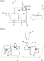
- FIG. 1 shows a schematic illustration of an optoelectronic sensor 10.
- Receiving light 14 is received by a light receiver 18 through a receiving optic 16 from a detection area 12 and a corresponding received signal is generated there.
- the received signal is evaluated in an evaluation unit 20 in order to obtain object information of an object in the detection area 12.
- This object information but also other information such as image data, auxiliary variables, parameters and the like, are exchanged via an interface 22 with an external device, for example a higher-level controller, not shown.
- a distance sensor 24 is provided.
- it is an autonomous, compact light transit time sensor with a light source 24a, a second light receiver 24b and a distance measuring unit 24c.
- the light source 24a emits light pulses which are received again by the second light receiver 24b after reflection on the object in the detection area 12, and the distance measuring unit 24c determines the light transit time between the transmission and reception of the light pulse.
- an amplitude-modulated light signal is emitted in a phase process and its phase shift is determined on receipt.
- the light receiver 18 and the evaluation unit 20 also take over or support the distance measurement in addition to obtaining object information, in particular by the light receiver 18 also functioning as the second light receiver 24b or the evaluation unit 20 also taking over the light transit time evaluation of the distance measurement unit 24c.
- the sensor 10 is preferably a camera in which the light receiver 18 is designed as a line or matrix-shaped image sensor.
- the camera is designed in particular as a code reader in that the evaluation unit 20 is able to identify the code area in the recorded images and to read out the information coded there.
- a barcode scanner is also a possible embodiment of the sensor 10.
- Other non-exhaustive examples of the sensor 10 are switching systems such as background-blanking buttons that react to objects with certain properties, and color or contrast buttons.
- further elements of the sensor 10 are possible, such as own lighting, not shown.
- Figure 2 shows a preferred mounting of the sensor 10, shown here simply as a camera symbol, above a conveyor belt 26, the sensor 10 here being in the form of a camera-based code reader, but the camera symbol is not intended to exclude either a bar code scanner or a comparable application example of another sensor 10.
- a stationary application of the sensor 10 on a conveyor belt 26 is advantageous, but the invention is not limited to this.
- the conveyor belt 26 conveys objects 28, as indicated by the arrow 30, through the detection area 12 of the sensor 10.
- the objects 28 have code areas 32 on their outer surfaces, which are detected and read out by the sensor 10. These code areas 32 can only be recognized by the sensor 10 if they are attached visibly on the upper side or at least from above.
- a plurality of sensors 10 can be mounted from different directions in order to read a code 34 attached approximately to the side or below.
- the arrangement of the plurality of sensors 10 to form a reading system usually takes the form of a reading tunnel.
- the sensor 10 detects object information as the primary target of the application via the light receiver 18 and evaluation of its received signal.
- object information In the example of a code reader, this is primarily the code content; in other cases, completely different object information can be sought, such as color, brightness, geometry, position or other optically detectable properties.
- a measured variable is determined from the received signal, which corresponds only exceptionally to the object information and is in most cases an auxiliary variable, such as a contrast, a medium gray value, the module or pixel size of a code 32 or whether code 32 could be read ( Goodread / Noread).
- an object distance is determined for the respective object 28, the object information of which is recorded, with the distance sensor 24.
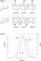
- Figure 3 shows a schematic representation of objects 28a-c at different distances from the sensor 10.
- the receiving optics 16 are set to the sharp detection of an object 28b at a medium distance, in the lower part to the sharp detection of an object 28a at a short distance.
- the depth of field 36 are indicated by the respective mutual distance of the lines shown therefor.
- the representation can also be understood as the depth of field 36 of a transmitting optics, for example as the size of the transmitted light spot in the case of a barcode scanner.
- the measured variable considered here as an example is the binary success rating GR (GoodRead), which assumes the value one if and only if a code 32 could be read.
- This success rating like its counterpart NoRead, is also recorded conventionally, but always only for a specific object 28.
- NoRead the binary success rating
- Only the reading rate has been recorded over a large number of objects 28, that is to say that a certain percentage of codes 32 could be read, which is indeed the capability well described, but no error analysis possible.
- d) is now determined, which indicates the probability with which a GoodRead results at a certain distance d.
- the code 32 is read each time an object 28 is detected and the associated GR is assigned to the distance measured for this object 28. A new data point thus arises with each further object 28, and a distribution is formed from the gradually acquired large number of data points, which estimates the conditional probability sought.
- GR depends on a variety of conditions.
- Figure 4 generalizes the example of Figure 3 and shows a distribution 38 of the conditional probability p (GR
- a further distribution 40 of the distances between the objects 28 themselves is formed as a comparison variable.
- the further distribution 40 is also assumed to be a Gaussian distribution, for example.
- the product 42 is also shown as a possible evaluation of the correspondence between the two distributions 38, 40.
- the sensor 10 is not optimized in this example. To do this, the two distributions 38, 40 should ideally overlap exactly, so that the best performance is achieved for the most frequently occurring cases.
- the sensor 10 can signal the optimization potential or, if accessible, change its settings itself in order to utilize it. For example, an iterative optimization is carried out using the product 42 or a maximum or center of gravity of the distributions 38, 40 is determined and brought into agreement.
- the measured variable is the binary success rating GR or its conditional probability p (GR
- the conclusion that the evaluation unit 20 draws from the distributions 38, 40 is a desired shift in the focus position by a certain distance. This shift is displayed for a fix focus device. It is also possible that the sensor 10 can translate the conversion of a shift ⁇ d of the focus position into a specific actuation instruction, such as "0.2 turns to the left". That depends on the lens model and possibly other ones Models such as the exposure / distance model and the adjustment mechanism of the receiving optics 16 and are therefore preferably stored as a table.
- the focal position can also by other parameters assessed as a success rating, such a contrast measure K, which is considered directly or as a conditional probability, whether it is in a specified range of values [K should -Tolerance, K to + tolerance] remains. Not only the measured variable can be changed, but also the possible change for the sensor 10, which was previously the focus position or, in a direct generalization, a misalignment of the optics or of the entire sensor 10.
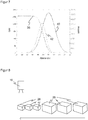
- Figure 5 illustrated in a similar representation Figure 3 another embodiment that deals with an intensity evaluation.
- statistical optimization is particularly helpful if the sensor 10 is not able to adapt its lighting parameters to the measured distance information for the currently detected object 28 in a highly dynamic manner.
- An average gray value GW is used as a concrete measurement.
- the intensity effectively detected by the sensor 10 depends on many factors such as the illumination, the reflectivity of the objects 28, their distance, an amplification factor in the reception path or the exposure time. It makes sense to adapt those parameters, such as illumination current, gain and exposure time, over which the sensor 10 has an influence, to the object distances actually occurring, so that the intensity for good decoding results remains as constant as possible and under- or overexposure is minimized in any case.
- d) can be determined that GW remains in the desired range.
- Figure 6 4 shows a corresponding generalized distribution 38 of p (GW
- d) p (GW
- the correct extent can again be found, for example, by iterative optimization or by determining the center or center of gravity of the distributions 38, 40, in particular by including the product 42.
- the intensity measure itself can also be considered. This is in the lower part of the Figure 5 shown.
- A) p (GW
- C) 0 and p (GW
- B) 1.
- Figure 7 shows the associated distribution 38 of the gray values over the distance. Overexposure at very close distances will always occur, therefore the distribution 38 cannot be brought into agreement with the distribution 40 of the object distances, but it can very well be in the best possible match, preferably on the basis of the product 42. Therefore, optimal lighting parameters can be found in sensors 10 or application situations, that do not allow highly dynamic lighting adaptation, both from the intensity measure GW itself and from the associated conditional probability p (GW
- the optimal lighting parameters can now be determined for an application that does not allow dynamic changes. In this way, signs of wear and soiling of the lighting, the light receiver 18, the receiving optics 16 and the like are compensated for.
- Figure 8 illustrates another embodiment. It is assumed here that objects 28 with the same object distance, in particular the same height, are actually objects of the same type. A particularly illustrative example are objects 28 of the same type which carry the same code 32.
- the sensor 10 first detects three small objects 28 which are the same as one another and then three higher objects 28 which are the same as one another, the sequence not being important due to the statistical processing and the objects 28 also appear mixed up allowed to.
- the objects 28, each with the same height also carry a code 32 with the same code size, thus module size, as well as the same code type and possibly the same or at least similar code position and orientation.
- an assumption is made in the distribution of the code properties of the code 32 to be read, because the distribution contains the information that an object 28 with a certain height is likely to have a code 32 with the code properties that have occurred most frequently so far.
- This information allows the software decoder to decode much faster, which first searches for code 32 in a specific ROI (region of interest) and tries to read a specific code type with a specific module size. If that fails, further reading attempts without these assumptions can follow.
- distributions of the object distances are formed from different time intervals and compared with one another. If there is a significant difference in this time comparison, the orientation of the sensor 10 may have been changed, for example by an impact, and the sensor 10 indicates that the alignment should be checked. Then you can as above Figure 3 described the adjustment of the optics can be improved.
- sensor 10 provides feedback about expected object properties, in particular code quality. Contrast or success assessment of the reading process are suitable as a measure. Similar to the example of Figure 8 For the object 28 just acquired, a contrast or read success to be expected from the distribution already determined is determined on the basis of its object distance. In addition, the actual contrast is determined or a reading process carried out and evaluated. Expectation and measurement are then compared. To put it simply, the idea here is that it must be due to code 32 if so far most or even all of codes 32 could be read at this distance, and only the code 32 currently being recorded could not. The assignment of a reading error to the sensor 10 or the code 32 can be further improved by considering the reliability of the expectation with a customary measure such as the standard deviation.
- two cases can appear somewhat more specifically.
- the code 32 is not printed well enough and has too little contrast. Since all codes 32 are normally read at this distance, it is likely that code 32 itself is the reason why the code content could not be read. If the contrast also deviates significantly from its normal value, a lack of contrast and thus poor print quality is probably the real reason.
- a read error (NoRead) also occurs, although codes 32 can usually be read at this distance. At the same time, the contrast is within the expected range, and therefore it is likely that the code 32 is damaged.
Priority Applications (3)
| Application Number | Priority Date | Filing Date | Title |
|---|---|---|---|
| EP18181130.8A EP3591567B1 (fr) | 2018-07-02 | 2018-07-02 | Capteur optoélectronique et procédé de détection optique répétitive d'objets à distance de l'objet différente |
| US16/458,723 US11068678B2 (en) | 2018-07-02 | 2019-07-01 | Optoelectronic sensor and method of a repeated optical detection of objects at different object distances |
| CN201910589200.8A CN110674649B (zh) | 2018-07-02 | 2019-07-02 | 重复光学检测不同对象距离处的对象的光电传感器和方法 |
Applications Claiming Priority (1)
| Application Number | Priority Date | Filing Date | Title |
|---|---|---|---|
| EP18181130.8A EP3591567B1 (fr) | 2018-07-02 | 2018-07-02 | Capteur optoélectronique et procédé de détection optique répétitive d'objets à distance de l'objet différente |
Publications (2)
| Publication Number | Publication Date |
|---|---|
| EP3591567A1 true EP3591567A1 (fr) | 2020-01-08 |
| EP3591567B1 EP3591567B1 (fr) | 2020-09-02 |
Family
ID=62873158
Family Applications (1)
| Application Number | Title | Priority Date | Filing Date |
|---|---|---|---|
| EP18181130.8A Active EP3591567B1 (fr) | 2018-07-02 | 2018-07-02 | Capteur optoélectronique et procédé de détection optique répétitive d'objets à distance de l'objet différente |
Country Status (3)
| Country | Link |
|---|---|
| US (1) | US11068678B2 (fr) |
| EP (1) | EP3591567B1 (fr) |
| CN (1) | CN110674649B (fr) |
Families Citing this family (4)
| Publication number | Priority date | Publication date | Assignee | Title |
|---|---|---|---|---|
| DE102020109929B3 (de) | 2020-04-09 | 2021-01-14 | Sick Ag | Erfassung von Bilddaten eines bewegten Objekts |
| DE102020113183B4 (de) * | 2020-05-15 | 2021-12-16 | Sick Ag | Kamera und Verfahren zur Erfassung von bewegten Objekten |
| US11523043B2 (en) | 2020-10-12 | 2022-12-06 | Apple Inc. | Camera autofocus using time-of-flight assistance |
| CN115190239B (zh) * | 2022-06-27 | 2024-04-19 | 联宝(合肥)电子科技有限公司 | 一种图像采集方法、装置、电子设备及存储介质 |
Citations (5)
| Publication number | Priority date | Publication date | Assignee | Title |
|---|---|---|---|---|
| EP1014292B1 (fr) | 1998-12-22 | 2003-05-02 | Datalogic S.P.A. | Méthode pour la régulation automatique des caractéristiques d'un sytème de lecture d'un code optique |
| EP0789315B1 (fr) | 1996-02-10 | 2006-05-10 | DATALOGIC S.p.A. | Méthode et appareil pour l'acquisition d'information assignée à des objets |
| EP2003599A1 (fr) * | 2007-06-14 | 2008-12-17 | Sick Ag | Capteur optoélectronique et procédé destiné à la saisie de codes |
| EP2693362A1 (fr) * | 2012-07-31 | 2014-02-05 | Sick Ag | Système de détection destiné à être monté sur une bande de transport |
| WO2018028795A1 (fr) * | 2016-08-12 | 2018-02-15 | Fastree3D Sa | Procédé et dispositif de mesure d'une distance par rapport à une cible dans un environnement multi-utilisateur au moyen d'au moins un détecteur |
Family Cites Families (7)
| Publication number | Priority date | Publication date | Assignee | Title |
|---|---|---|---|---|
| US6889903B1 (en) * | 1988-08-31 | 2005-05-10 | Intermec Ip Corp. | Method and apparatus for optically reading information |
| US6830189B2 (en) * | 1995-12-18 | 2004-12-14 | Metrologic Instruments, Inc. | Method of and system for producing digital images of objects with subtantially reduced speckle-noise patterns by illuminating said objects with spatially and/or temporally coherent-reduced planar laser illumination |
| JP4789482B2 (ja) * | 2005-02-18 | 2011-10-12 | 株式会社キーエンス | 位置検出型光電センサーとその基準距離設定方法 |
| US20080245872A1 (en) * | 2007-04-05 | 2008-10-09 | Good Timothy A | Barcode scanner/reader having constantly varying focal distance |
| US8632011B2 (en) * | 2011-01-18 | 2014-01-21 | Datalogic ADC, Inc. | Systems and methods for illuminating a scan volume of an optical code reader |
| US8939369B2 (en) * | 2011-01-24 | 2015-01-27 | Datalogic ADC, Inc. | Exception detection and handling in automated optical code reading systems |
| CN106597463B (zh) * | 2016-12-29 | 2019-03-29 | 天津师范大学 | 基于动态视觉传感器芯片的光电式接近传感器及探测方法 |
-
2018
- 2018-07-02 EP EP18181130.8A patent/EP3591567B1/fr active Active
-
2019
- 2019-07-01 US US16/458,723 patent/US11068678B2/en active Active
- 2019-07-02 CN CN201910589200.8A patent/CN110674649B/zh active Active
Patent Citations (5)
| Publication number | Priority date | Publication date | Assignee | Title |
|---|---|---|---|---|
| EP0789315B1 (fr) | 1996-02-10 | 2006-05-10 | DATALOGIC S.p.A. | Méthode et appareil pour l'acquisition d'information assignée à des objets |
| EP1014292B1 (fr) | 1998-12-22 | 2003-05-02 | Datalogic S.P.A. | Méthode pour la régulation automatique des caractéristiques d'un sytème de lecture d'un code optique |
| EP2003599A1 (fr) * | 2007-06-14 | 2008-12-17 | Sick Ag | Capteur optoélectronique et procédé destiné à la saisie de codes |
| EP2693362A1 (fr) * | 2012-07-31 | 2014-02-05 | Sick Ag | Système de détection destiné à être monté sur une bande de transport |
| WO2018028795A1 (fr) * | 2016-08-12 | 2018-02-15 | Fastree3D Sa | Procédé et dispositif de mesure d'une distance par rapport à une cible dans un environnement multi-utilisateur au moyen d'au moins un détecteur |
Also Published As
| Publication number | Publication date |
|---|---|
| CN110674649B (zh) | 2023-08-04 |
| EP3591567B1 (fr) | 2020-09-02 |
| US20200005006A1 (en) | 2020-01-02 |
| US11068678B2 (en) | 2021-07-20 |
| CN110674649A (zh) | 2020-01-10 |
Similar Documents
| Publication | Publication Date | Title |
|---|---|---|
| EP3591567B1 (fr) | Capteur optoélectronique et procédé de détection optique répétitive d'objets à distance de l'objet différente | |
| DE102018105301B4 (de) | Kamera und Verfahren zur Erfassung von Bilddaten | |
| EP2693363B1 (fr) | Système de caméra et procédé de détermination d'un flux d'objets | |
| EP3428834B1 (fr) | Lecteur de code optoélectronique et procédé de lecture de code optique | |
| EP1645839B1 (fr) | Dispositif et procédé pour surveiller des objets en motion | |
| EP2546776B1 (fr) | Lecteur de code basé sur un appareil de prise de vue et son procédé de fabrication ajustée | |
| EP3663963B1 (fr) | Lecture de codes optiques | |
| EP1158460B1 (fr) | Système et procédé de traitement d'images | |
| EP1845336A1 (fr) | Procédé et dispositif pour la détection optique des objets en mouvement | |
| DE102014104026B3 (de) | Optoelektronische Vorrichtung und Verfahren zum Aufnehmen eines Bildes | |
| EP3893051B1 (fr) | Acquisition de données d'image d'un objet mobile | |
| EP3812953B1 (fr) | Lecteur de codes et procédé de lecture des codes optiques | |
| EP3892955B1 (fr) | Caméra et procédé de détection des données d'image | |
| EP2701380A1 (fr) | Caméra et procédé d'enregistrement d'image nettes | |
| DE69814105T2 (de) | Verfahren zur automatischen Regulierung der Eigenschaften eines optischen Codelesesystems | |
| EP1146353A2 (fr) | Dispositif détecteur optoélectronique et méthode pour actionner un dispositif détecteur optoélectronique | |
| EP4075394B1 (fr) | Détection d'un flux mobile d'objets | |
| DE102014114506A1 (de) | Kamera zur Montage an einer Fördereinrichtung und Verfahren zur Inspektion oder Identifikation | |
| EP1197910B1 (fr) | Dispositif et méthode pour la reconnaissance de codes | |
| EP3910547B1 (fr) | Détection des objets mobiles | |
| DE102009036389A1 (de) | Verfahren und Vorrichtung zur Überprüfung von mit Gefäßen bestückten oder bestückbaren, oben offenen Aufnahmebehältern | |
| DE202015100438U1 (de) | Optoelektronischer Sensor zur Erfassung von Objektinformationen | |
| DE202013101489U1 (de) | Kamera zur Aufnahme scharfer Bilder | |
| DE102019128710B4 (de) | Kamera und Verfahren zur Erfassung von Bilddaten aus einem Erfassungsbereich | |
| EP4102293B1 (fr) | Caméra et procédé de détection des objets se déplaçant dans une zone de détection |
Legal Events
| Date | Code | Title | Description |
|---|---|---|---|
| PUAI | Public reference made under article 153(3) epc to a published international application that has entered the european phase |
Free format text: ORIGINAL CODE: 0009012 |
|
| STAA | Information on the status of an ep patent application or granted ep patent |
Free format text: STATUS: REQUEST FOR EXAMINATION WAS MADE |
|
| 17P | Request for examination filed |
Effective date: 20190502 |
|
| AK | Designated contracting states |
Kind code of ref document: A1 Designated state(s): AL AT BE BG CH CY CZ DE DK EE ES FI FR GB GR HR HU IE IS IT LI LT LU LV MC MK MT NL NO PL PT RO RS SE SI SK SM TR |
|
| AX | Request for extension of the european patent |
Extension state: BA ME |
|
| RAP1 | Party data changed (applicant data changed or rights of an application transferred) |
Owner name: SICK AG |
|
| GRAP | Despatch of communication of intention to grant a patent |
Free format text: ORIGINAL CODE: EPIDOSNIGR1 |
|
| STAA | Information on the status of an ep patent application or granted ep patent |
Free format text: STATUS: GRANT OF PATENT IS INTENDED |
|
| INTG | Intention to grant announced |
Effective date: 20200320 |
|
| GRAS | Grant fee paid |
Free format text: ORIGINAL CODE: EPIDOSNIGR3 |
|
| GRAA | (expected) grant |
Free format text: ORIGINAL CODE: 0009210 |
|
| STAA | Information on the status of an ep patent application or granted ep patent |
Free format text: STATUS: THE PATENT HAS BEEN GRANTED |
|
| AK | Designated contracting states |
Kind code of ref document: B1 Designated state(s): AL AT BE BG CH CY CZ DE DK EE ES FI FR GB GR HR HU IE IS IT LI LT LU LV MC MK MT NL NO PL PT RO RS SE SI SK SM TR |
|
| REG | Reference to a national code |
Ref country code: GB Ref legal event code: FG4D Free format text: NOT ENGLISH |
|
| REG | Reference to a national code |
Ref country code: AT Ref legal event code: REF Ref document number: 1309678 Country of ref document: AT Kind code of ref document: T Effective date: 20200915 Ref country code: CH Ref legal event code: EP |
|
| REG | Reference to a national code |
Ref country code: DE Ref legal event code: R096 Ref document number: 502018002321 Country of ref document: DE |
|
| REG | Reference to a national code |
Ref country code: IE Ref legal event code: FG4D Free format text: LANGUAGE OF EP DOCUMENT: GERMAN |
|
| REG | Reference to a national code |
Ref country code: NL Ref legal event code: FP |
|
| REG | Reference to a national code |
Ref country code: SE Ref legal event code: TRGR |
|
| REG | Reference to a national code |
Ref country code: LT Ref legal event code: MG4D |
|
| PG25 | Lapsed in a contracting state [announced via postgrant information from national office to epo] |
Ref country code: HR Free format text: LAPSE BECAUSE OF FAILURE TO SUBMIT A TRANSLATION OF THE DESCRIPTION OR TO PAY THE FEE WITHIN THE PRESCRIBED TIME-LIMIT Effective date: 20200902 Ref country code: LT Free format text: LAPSE BECAUSE OF FAILURE TO SUBMIT A TRANSLATION OF THE DESCRIPTION OR TO PAY THE FEE WITHIN THE PRESCRIBED TIME-LIMIT Effective date: 20200902 Ref country code: BG Free format text: LAPSE BECAUSE OF FAILURE TO SUBMIT A TRANSLATION OF THE DESCRIPTION OR TO PAY THE FEE WITHIN THE PRESCRIBED TIME-LIMIT Effective date: 20201202 Ref country code: NO Free format text: LAPSE BECAUSE OF FAILURE TO SUBMIT A TRANSLATION OF THE DESCRIPTION OR TO PAY THE FEE WITHIN THE PRESCRIBED TIME-LIMIT Effective date: 20201202 Ref country code: GR Free format text: LAPSE BECAUSE OF FAILURE TO SUBMIT A TRANSLATION OF THE DESCRIPTION OR TO PAY THE FEE WITHIN THE PRESCRIBED TIME-LIMIT Effective date: 20201203 Ref country code: FI Free format text: LAPSE BECAUSE OF FAILURE TO SUBMIT A TRANSLATION OF THE DESCRIPTION OR TO PAY THE FEE WITHIN THE PRESCRIBED TIME-LIMIT Effective date: 20200902 |
|
| PG25 | Lapsed in a contracting state [announced via postgrant information from national office to epo] |
Ref country code: LV Free format text: LAPSE BECAUSE OF FAILURE TO SUBMIT A TRANSLATION OF THE DESCRIPTION OR TO PAY THE FEE WITHIN THE PRESCRIBED TIME-LIMIT Effective date: 20200902 Ref country code: PL Free format text: LAPSE BECAUSE OF FAILURE TO SUBMIT A TRANSLATION OF THE DESCRIPTION OR TO PAY THE FEE WITHIN THE PRESCRIBED TIME-LIMIT Effective date: 20200902 Ref country code: RS Free format text: LAPSE BECAUSE OF FAILURE TO SUBMIT A TRANSLATION OF THE DESCRIPTION OR TO PAY THE FEE WITHIN THE PRESCRIBED TIME-LIMIT Effective date: 20200902 |
|
| PG25 | Lapsed in a contracting state [announced via postgrant information from national office to epo] |
Ref country code: CZ Free format text: LAPSE BECAUSE OF FAILURE TO SUBMIT A TRANSLATION OF THE DESCRIPTION OR TO PAY THE FEE WITHIN THE PRESCRIBED TIME-LIMIT Effective date: 20200902 Ref country code: RO Free format text: LAPSE BECAUSE OF FAILURE TO SUBMIT A TRANSLATION OF THE DESCRIPTION OR TO PAY THE FEE WITHIN THE PRESCRIBED TIME-LIMIT Effective date: 20200902 Ref country code: PT Free format text: LAPSE BECAUSE OF FAILURE TO SUBMIT A TRANSLATION OF THE DESCRIPTION OR TO PAY THE FEE WITHIN THE PRESCRIBED TIME-LIMIT Effective date: 20210104 Ref country code: EE Free format text: LAPSE BECAUSE OF FAILURE TO SUBMIT A TRANSLATION OF THE DESCRIPTION OR TO PAY THE FEE WITHIN THE PRESCRIBED TIME-LIMIT Effective date: 20200902 Ref country code: SM Free format text: LAPSE BECAUSE OF FAILURE TO SUBMIT A TRANSLATION OF THE DESCRIPTION OR TO PAY THE FEE WITHIN THE PRESCRIBED TIME-LIMIT Effective date: 20200902 |
|
| PG25 | Lapsed in a contracting state [announced via postgrant information from national office to epo] |
Ref country code: ES Free format text: LAPSE BECAUSE OF FAILURE TO SUBMIT A TRANSLATION OF THE DESCRIPTION OR TO PAY THE FEE WITHIN THE PRESCRIBED TIME-LIMIT Effective date: 20200902 Ref country code: AL Free format text: LAPSE BECAUSE OF FAILURE TO SUBMIT A TRANSLATION OF THE DESCRIPTION OR TO PAY THE FEE WITHIN THE PRESCRIBED TIME-LIMIT Effective date: 20200902 Ref country code: IS Free format text: LAPSE BECAUSE OF FAILURE TO SUBMIT A TRANSLATION OF THE DESCRIPTION OR TO PAY THE FEE WITHIN THE PRESCRIBED TIME-LIMIT Effective date: 20210102 |
|
| REG | Reference to a national code |
Ref country code: DE Ref legal event code: R097 Ref document number: 502018002321 Country of ref document: DE |
|
| PG25 | Lapsed in a contracting state [announced via postgrant information from national office to epo] |
Ref country code: SK Free format text: LAPSE BECAUSE OF FAILURE TO SUBMIT A TRANSLATION OF THE DESCRIPTION OR TO PAY THE FEE WITHIN THE PRESCRIBED TIME-LIMIT Effective date: 20200902 |
|
| PLBE | No opposition filed within time limit |
Free format text: ORIGINAL CODE: 0009261 |
|
| STAA | Information on the status of an ep patent application or granted ep patent |
Free format text: STATUS: NO OPPOSITION FILED WITHIN TIME LIMIT |
|
| 26N | No opposition filed |
Effective date: 20210603 |
|
| PG25 | Lapsed in a contracting state [announced via postgrant information from national office to epo] |
Ref country code: DK Free format text: LAPSE BECAUSE OF FAILURE TO SUBMIT A TRANSLATION OF THE DESCRIPTION OR TO PAY THE FEE WITHIN THE PRESCRIBED TIME-LIMIT Effective date: 20200902 |
|
| PG25 | Lapsed in a contracting state [announced via postgrant information from national office to epo] |
Ref country code: MC Free format text: LAPSE BECAUSE OF FAILURE TO SUBMIT A TRANSLATION OF THE DESCRIPTION OR TO PAY THE FEE WITHIN THE PRESCRIBED TIME-LIMIT Effective date: 20200902 |
|
| PG25 | Lapsed in a contracting state [announced via postgrant information from national office to epo] |
Ref country code: LU Free format text: LAPSE BECAUSE OF NON-PAYMENT OF DUE FEES Effective date: 20210702 |
|
| PG25 | Lapsed in a contracting state [announced via postgrant information from national office to epo] |
Ref country code: IE Free format text: LAPSE BECAUSE OF NON-PAYMENT OF DUE FEES Effective date: 20210702 |
|
| PG25 | Lapsed in a contracting state [announced via postgrant information from national office to epo] |
Ref country code: CY Free format text: LAPSE BECAUSE OF FAILURE TO SUBMIT A TRANSLATION OF THE DESCRIPTION OR TO PAY THE FEE WITHIN THE PRESCRIBED TIME-LIMIT Effective date: 20200902 |
|
| PG25 | Lapsed in a contracting state [announced via postgrant information from national office to epo] |
Ref country code: HU Free format text: LAPSE BECAUSE OF FAILURE TO SUBMIT A TRANSLATION OF THE DESCRIPTION OR TO PAY THE FEE WITHIN THE PRESCRIBED TIME-LIMIT; INVALID AB INITIO Effective date: 20180702 |
|
| PGFP | Annual fee paid to national office [announced via postgrant information from national office to epo] |
Ref country code: NL Payment date: 20230720 Year of fee payment: 6 |
|
| PG25 | Lapsed in a contracting state [announced via postgrant information from national office to epo] |
Ref country code: SI Free format text: LAPSE BECAUSE OF FAILURE TO SUBMIT A TRANSLATION OF THE DESCRIPTION OR TO PAY THE FEE WITHIN THE PRESCRIBED TIME-LIMIT Effective date: 20200902 |
|
| PGFP | Annual fee paid to national office [announced via postgrant information from national office to epo] |
Ref country code: IT Payment date: 20230731 Year of fee payment: 6 Ref country code: GB Payment date: 20230724 Year of fee payment: 6 Ref country code: CH Payment date: 20230801 Year of fee payment: 6 Ref country code: AT Payment date: 20230718 Year of fee payment: 6 |
|
| PGFP | Annual fee paid to national office [announced via postgrant information from national office to epo] |
Ref country code: SE Payment date: 20230724 Year of fee payment: 6 Ref country code: FR Payment date: 20230724 Year of fee payment: 6 Ref country code: DE Payment date: 20230720 Year of fee payment: 6 Ref country code: BE Payment date: 20230719 Year of fee payment: 6 |
|
| PG25 | Lapsed in a contracting state [announced via postgrant information from national office to epo] |
Ref country code: MK Free format text: LAPSE BECAUSE OF FAILURE TO SUBMIT A TRANSLATION OF THE DESCRIPTION OR TO PAY THE FEE WITHIN THE PRESCRIBED TIME-LIMIT Effective date: 20200902 |