EP3591496B1 - Dispositif de visualisation à écran tactile comportant un accroche-doigts - Google Patents
Dispositif de visualisation à écran tactile comportant un accroche-doigts Download PDFInfo
- Publication number
- EP3591496B1 EP3591496B1 EP19182268.3A EP19182268A EP3591496B1 EP 3591496 B1 EP3591496 B1 EP 3591496B1 EP 19182268 A EP19182268 A EP 19182268A EP 3591496 B1 EP3591496 B1 EP 3591496B1
- Authority
- EP
- European Patent Office
- Prior art keywords
- frame
- flange
- equal
- front face
- display device
- Prior art date
- Legal status (The legal status is an assumption and is not a legal conclusion. Google has not performed a legal analysis and makes no representation as to the accuracy of the status listed.)
- Active
Links
Images


Classifications
-
- G—PHYSICS
- G06—COMPUTING OR CALCULATING; COUNTING
- G06F—ELECTRIC DIGITAL DATA PROCESSING
- G06F3/00—Input arrangements for transferring data to be processed into a form capable of being handled by the computer; Output arrangements for transferring data from processing unit to output unit, e.g. interface arrangements
- G06F3/01—Input arrangements or combined input and output arrangements for interaction between user and computer
- G06F3/03—Arrangements for converting the position or the displacement of a member into a coded form
- G06F3/041—Digitisers, e.g. for touch screens or touch pads, characterised by the transducing means
- G06F3/0416—Control or interface arrangements specially adapted for digitisers
- G06F3/0418—Control or interface arrangements specially adapted for digitisers for error correction or compensation, e.g. based on parallax, calibration or alignment
-
- G—PHYSICS
- G06—COMPUTING OR CALCULATING; COUNTING
- G06F—ELECTRIC DIGITAL DATA PROCESSING
- G06F1/00—Details not covered by groups G06F3/00 - G06F13/00 and G06F21/00
- G06F1/16—Constructional details or arrangements
- G06F1/1601—Constructional details related to the housing of computer displays, e.g. of CRT monitors, of flat displays
-
- B—PERFORMING OPERATIONS; TRANSPORTING
- B60—VEHICLES IN GENERAL
- B60K—ARRANGEMENT OR MOUNTING OF PROPULSION UNITS OR OF TRANSMISSIONS IN VEHICLES; ARRANGEMENT OR MOUNTING OF PLURAL DIVERSE PRIME-MOVERS IN VEHICLES; AUXILIARY DRIVES FOR VEHICLES; INSTRUMENTATION OR DASHBOARDS FOR VEHICLES; ARRANGEMENTS IN CONNECTION WITH COOLING, AIR INTAKE, GAS EXHAUST OR FUEL SUPPLY OF PROPULSION UNITS IN VEHICLES
- B60K35/00—Instruments specially adapted for vehicles; Arrangement of instruments in or on vehicles
- B60K35/10—Input arrangements, i.e. from user to vehicle, associated with vehicle functions or specially adapted therefor
-
- B—PERFORMING OPERATIONS; TRANSPORTING
- B60—VEHICLES IN GENERAL
- B60K—ARRANGEMENT OR MOUNTING OF PROPULSION UNITS OR OF TRANSMISSIONS IN VEHICLES; ARRANGEMENT OR MOUNTING OF PLURAL DIVERSE PRIME-MOVERS IN VEHICLES; AUXILIARY DRIVES FOR VEHICLES; INSTRUMENTATION OR DASHBOARDS FOR VEHICLES; ARRANGEMENTS IN CONNECTION WITH COOLING, AIR INTAKE, GAS EXHAUST OR FUEL SUPPLY OF PROPULSION UNITS IN VEHICLES
- B60K35/00—Instruments specially adapted for vehicles; Arrangement of instruments in or on vehicles
- B60K35/20—Output arrangements, i.e. from vehicle to user, associated with vehicle functions or specially adapted therefor
- B60K35/21—Output arrangements, i.e. from vehicle to user, associated with vehicle functions or specially adapted therefor using visual output, e.g. blinking lights or matrix displays
- B60K35/22—Display screens
-
- B—PERFORMING OPERATIONS; TRANSPORTING
- B60—VEHICLES IN GENERAL
- B60K—ARRANGEMENT OR MOUNTING OF PROPULSION UNITS OR OF TRANSMISSIONS IN VEHICLES; ARRANGEMENT OR MOUNTING OF PLURAL DIVERSE PRIME-MOVERS IN VEHICLES; AUXILIARY DRIVES FOR VEHICLES; INSTRUMENTATION OR DASHBOARDS FOR VEHICLES; ARRANGEMENTS IN CONNECTION WITH COOLING, AIR INTAKE, GAS EXHAUST OR FUEL SUPPLY OF PROPULSION UNITS IN VEHICLES
- B60K35/00—Instruments specially adapted for vehicles; Arrangement of instruments in or on vehicles
- B60K35/80—Arrangements for controlling instruments
-
- B—PERFORMING OPERATIONS; TRANSPORTING
- B60—VEHICLES IN GENERAL
- B60K—ARRANGEMENT OR MOUNTING OF PROPULSION UNITS OR OF TRANSMISSIONS IN VEHICLES; ARRANGEMENT OR MOUNTING OF PLURAL DIVERSE PRIME-MOVERS IN VEHICLES; AUXILIARY DRIVES FOR VEHICLES; INSTRUMENTATION OR DASHBOARDS FOR VEHICLES; ARRANGEMENTS IN CONNECTION WITH COOLING, AIR INTAKE, GAS EXHAUST OR FUEL SUPPLY OF PROPULSION UNITS IN VEHICLES
- B60K37/00—Dashboards
-
- B—PERFORMING OPERATIONS; TRANSPORTING
- B64—AIRCRAFT; AVIATION; COSMONAUTICS
- B64D—EQUIPMENT FOR FITTING IN OR TO AIRCRAFT; FLIGHT SUITS; PARACHUTES; ARRANGEMENT OR MOUNTING OF POWER PLANTS OR PROPULSION TRANSMISSIONS IN AIRCRAFT
- B64D43/00—Arrangements or adaptations of instruments
-
- G—PHYSICS
- G06—COMPUTING OR CALCULATING; COUNTING
- G06F—ELECTRIC DIGITAL DATA PROCESSING
- G06F3/00—Input arrangements for transferring data to be processed into a form capable of being handled by the computer; Output arrangements for transferring data from processing unit to output unit, e.g. interface arrangements
- G06F3/01—Input arrangements or combined input and output arrangements for interaction between user and computer
- G06F3/03—Arrangements for converting the position or the displacement of a member into a coded form
- G06F3/041—Digitisers, e.g. for touch screens or touch pads, characterised by the transducing means
-
- H—ELECTRICITY
- H05—ELECTRIC TECHNIQUES NOT OTHERWISE PROVIDED FOR
- H05K—PRINTED CIRCUITS; CASINGS OR CONSTRUCTIONAL DETAILS OF ELECTRIC APPARATUS; MANUFACTURE OF ASSEMBLAGES OF ELECTRICAL COMPONENTS
- H05K5/00—Casings, cabinets or drawers for electric apparatus
- H05K5/02—Details
- H05K5/0217—Mechanical details of casings
- H05K5/023—Handles; Grips
Definitions
- the field of the invention is that of touch screens mounted on dashboards or instrument panels of vehicles. More specifically, the preferred field of the invention is that of air transport and touch screens mounted on aircraft instrument panels.
- dashboards are increasingly equipped with display screens with touch surfaces that allow simple and ergonomic interaction with the displayed functions.
- touch screens must be able to be used in conditions of significant vibration due, for example, to atmospheric turbulence or, for military aircraft, to specific phases of maneuver or combat.
- Other types of vehicles encounter similar problems, such as off-road vehicles, which may be subject to significant vibrations or accelerations. These conditions experienced by the user partially hinder their ability to interact precisely with the touch screen, which can lead to involuntary interactions with the screen.
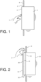
- FIG. 1 illustrates this problem. It represents a display device 1 comprising on its front face 2 a touch-sensitive surface 3. It is mounted on a dashboard 4.
- a display device 1 comprising on its front face 2 a touch-sensitive surface 3. It is mounted on a dashboard 4.
- the hand of the user U has no grip on the touch screen and the precision of the gesture deteriorates significantly.
- the effects of the disturbances are all the more significant when the screen is at a certain distance from the user, requiring him to stretch his arm to be able to carry out the action, which further increases the imprecision of the gesture.
- Replacing graphic pointing devices with touch-sensitive surfaces has several advantages. It allows for direct and rapid interaction with, for example, a displayed menu. It opens up the possibility of new functions performed, for example, by coordinated movements of one or more fingers, such as "Zoom" functions. However, direct interaction on a screen reduces the possibility of stabilization offered by a traditional physical means such as a control button or a pointing device and can generate muscle fatigue, given the user's distance from the screen.
- the request WO01/00435 entitled “Device for fixing instruments on an instrument panel” describes a device for fixing an instrument, such as a liquid crystal display, on a dashboard with recesses.
- the application US 2012/0 105 335 entitled “Touch screen display assembly” describes a display screen comprising, again, a surround comprising support surfaces whose materials and shapes have been worked in such a way as to increase their grip.
- the display device according to the invention does not have the above drawbacks. It is simple, inexpensive, easy to implement and effective.
- the device according to the invention comprises a touch-sensitive surface whose frame has, around its periphery, a rigid collar used as a "finger grip". It has been successfully tested under experimental conditions. In particular, it has been demonstrated that stability, during turbulence, is better if the user can hook their fingers at the screen so that the hand is in traction. In this case, the traction is exerted by the index finger accompanied by the middle and ring fingers, the thumb ensuring the action on the touch screen. Simply exerting pressure on the edge of the screen does not ensure the same level of stability. Thus, the most ergonomic shapes of finger grips could be determined.
- the industrialization of the finger hooks according to the invention is easy to implement since the parts are simple to machine.
- it is easy to modify an existing visualization frame by adding the finger hooks according to the invention.
- the invention relates to a display device as claimed in claim 1.
- the frame comprises a plurality of markers arranged on at least one side of the periphery of the frame, said markers being separated by a constant distance.
- the frame comprises a plurality of markers arranged on at least one side of the periphery of the frame, said markers being separated by a variable distance.
- the invention also relates to a display device as claimed in claim 4.
- the frame comprises a plurality of notches arranged on at least one side of the periphery of the frame, said notches being separated by a constant distance.
- the frame comprises a plurality of notches arranged on at least one side of the periphery of the frame, said notches being separated by a variable distance.
- the Figure 2 represents a general view of a first embodiment of a display device comprising a touch surface frame according to the invention.
- the display devices are mounted on aircraft dashboards.
- the “finger hook” system according to the invention can be mounted on all types of land or sea vehicles likely to be subject to significant acceleration or vibration.
- the display device 10 comprises a front face 20 on which a touch surface 30 is mounted.
- the device according to the invention can be adapted to all types of display device and touch surface.
- the display device comprises a support face 21 on the dashboard 40, the front face 20 and the support face 21 having rectangular shapes.
- the support face may comprise means for fixing the display device to the dashboard which are known to those skilled in the art.
- the touch surface 30 is surrounded by a rigid frame 31.
- This frame is generally metallic.
- This frame 31 comprises, on its periphery, a collar 32 located in the extension of the front face.
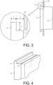
- the Figure 3 represents an enlarged partial sectional view of the neck of the Figure 2 .
- the section of this collar 32 in a plane perpendicular to the front face is substantially rectangular, the collar surmounting the front face by a height H of a few millimeters. More precisely, this height is equal to or greater than 3 millimeters. Its depth P is also a few millimeters. More precisely, its depth is equal to or greater than 3 millimeters.
- the distance D separating the internal wall of this collar from the bearing face is equal to or greater than 10 millimeters.
- FIG. 4 represents an enlarged partial perspective view of the frame 31 and the collar 32 of the figures 2 And 3 .
- FIG. 5 represents a general view of an alternative embodiment of the touch surface frame of the Figure 2 .
- the frame 31 comprises one or more markers 33 arranged between the internal wall of the collar 32 and the bearing face 21, each marker 33 having a shape substantially parallelepiped, its height being that of the collar, its depth being equal to the distance separating the internal wall of the collar from the support face, its width being equal to or greater than 5 millimeters.
- markers have a dual purpose. They help to better ensure the user's finger grip. Particularly on the sides of the screen, the markers provide good vertical stabilization and counter the effects of gravity, thus preventing the hand from sliding down the screen. They also make it easy to find your way around the touch surface. They can be separated by a constant distance so as, for example, to divide the edge of the screen into zones of equal dimensions. They can also be placed at predefined positions corresponding to particular functions addressed by the touch surface. These markers can all be identical or of different shapes to better identify them. On the Figures 5 and 6 , the markers are parallelepiped in shape but other shapes are possible. Some parts may be rounded to facilitate gripping. Generally speaking, any change in shape or dimensions of these markers remains within the scope of the display device according to the invention.
- FIG. 6 represents an enlarged partial perspective view of the frame 31, the collar 32 and the marks 33 of the Figure 5 .
- the frame 31 comprises, on its periphery, a collar 34 located in the extension of the front face, the section of this collar in a plane perpendicular to the front face being rectangular, the collar surmounting the front face by a height equal to or greater than 3 millimeters, its depth being equal to the distance separating the internal wall of this collar from the bearing face.
- the collar 34 comprises notches 35 having a substantially parallelepiped shape.
- the depth of the notch is a few millimeters and preferably, it is equal to or greater than 3 millimeters, its length being equal to the distance separating the internal wall of the collar from the bearing face, its width is a few millimeters and preferably, this width is equal to or greater than 5 millimeters.
- FIG 8 represents an enlarged partial perspective view of the frame 31, the collar 32 and the notches 35 of the Figure 7 .
- these notches have a dual purpose. They allow the user's fingers to better grip. Particularly on the sides of the screen, the notches provide good vertical stabilization and counter the effects of gravity, thus preventing the hand from sliding down the screen. They also make it easy to find your way around the touch surface. Thus, they can be separated by a constant distance so as, for example, to divide the edge of the screen into zones of equal dimensions. They can also be placed at predefined positions corresponding to particular functions addressed by the touch surface. These notches can all be identical or of different shapes to better identify them. On the figures 7 and 8 , the notches are parallelepiped in shape but other shapes are possible. Some parts may be rounded to facilitate gripping. Generally speaking, any change in shape or dimensions of these notches remains within the scope of the viewing device according to the invention.
- the main advantages of the "finger grips" according to the invention are that they are simple to machine, require only simple changes to the shape of the frame and are practically wear-free. Furthermore, they introduce very little visual obstruction since a rim of a few millimeters is sufficient to ensure a correct grip for the user.
- the shape of the finger grips does not depend on the position of the screen. Screens can be exchanged in the event of a failure. This limits production costs.
- a final advantage is that this finger grip solution allows freedom of movement of the hand along the viewing device, while maintaining the desired stabilization.
Landscapes
- Engineering & Computer Science (AREA)
- Chemical & Material Sciences (AREA)
- Mechanical Engineering (AREA)
- Transportation (AREA)
- Combustion & Propulsion (AREA)
- General Engineering & Computer Science (AREA)
- Theoretical Computer Science (AREA)
- General Physics & Mathematics (AREA)
- Physics & Mathematics (AREA)
- Human Computer Interaction (AREA)
- Computer Hardware Design (AREA)
- Microelectronics & Electronic Packaging (AREA)
- Aviation & Aerospace Engineering (AREA)
- Instrument Panels (AREA)
- Devices For Indicating Variable Information By Combining Individual Elements (AREA)
- Position Input By Displaying (AREA)
- Fittings On The Vehicle Exterior For Carrying Loads, And Devices For Holding Or Mounting Articles (AREA)
Description
- Le domaine de l'invention est celui des écrans tactiles montés sur des tableaux de bord ou des planches de bord de véhicules. Plus spécifiquement, le domaine privilégié de l'invention est celui du transport aérien et des écrans tactiles montés sur les planches de bord des aéronefs.
- En aéronautique, les planches de bord sont de plus en plus souvent munies d'écrans de visualisation comportant des surfaces tactiles permettant d'interagir de façon simple et ergonomique avec les fonctions affichées. L'utilisation de ces écrans tactiles doit pouvoir se faire dans des conditions de vibrations importantes dues, par exemple, aux turbulences atmosphériques ou, pour les aéronefs militaires, à des phases particulières de manœuvre ou de combat. D'autres types de véhicules rencontrent des problèmes du même ordre comme, par exemple, les véhicules tout-terrain qui peuvent être soumis à des vibrations ou des accélérations importantes. Ces conditions ressenties par l'utilisateur entravent en partie sa capacité à interagir de façon précise avec l'écran tactile, pouvant entraîner des interactions involontaires avec l'écran.
- La
figure 1 illustre ce problème. Elle représente un dispositif de visualisation 1 comportant sur sa face avant 2 une surface tactile 3. Il est monté sur une planche de bord 4. Lorsque celle-ci est soumise, par exemple, à des vibrations, la main de l'utilisateur U n'a aucune prise sur l'écran tactile et la précision du geste se dégrade fortement. Les effets des perturbations sont d'autant plus significatifs que l'écran se trouve à une certaine distance de l'utilisateur, lui imposant de tendre le bras pour pouvoir réaliser l'action, ce qui augmente encore l'imprécision du geste. - Ce problème est récent. Dans le passé, les moyens de contrôle et d'interaction étaient essentiellement des postes de commande comportant des boutons physiques tels que des boutons poussoirs ou des boutons rotatifs qui permettaient une prise en main correcte par l'utilisateur avant d'engager l'action. L'introduction de dispositifs de visualisation a permis de réduire considérablement le nombre d'équipements dans un poste de pilotage, de diminuer ainsi le poids et l'encombrement et d'améliorer l'ergonomie de la présentation d'informations. Ces dispositifs de visualisation ont initialement été contrôlés par des dispositifs de pointage graphique du type « souris informatique » ou « CCD », acronyme de « Cursor Control Device ». Ces dispositifs de pointage présentent les mêmes avantages que les postes de commande. On peut facilement stabiliser la main, par exemple, sur un « repose-paume » et positionner correctement le pointeur graphique sur l'écran de visualisation.
- Le remplacement des dispositifs de pointage graphique par des surfaces tactiles a plusieurs avantages. Il permet d'avoir une interaction directe et rapide avec, par exemple, un menu affiché. Il ouvre la possibilité à de nouvelles fonctions réalisées, par exemple, par des mouvements coordonnés d'un doigt ou de plusieurs doigts comme les fonctions « Zoom ». Néanmoins, l'interaction directe sur un écran réduit la possibilité de stabilisation qu'offre un moyen physique traditionnel tel qu'un bouton de commande ou un dispositif de pointage et peut générer de la fatigue musculaire, compte-tenu de la distance de l'utilisateur à l'écran.
- Pour résoudre ce problème, différentes solutions techniques ont été proposées. Le brevet
US 9 348 446 - Le brevet
US 9 870 093 - La demande
US 2017/0 075 442 intitulée « Touch screen bezel design for use in aviation operations » décrit un écran de visualisation comportant un entourage dont les surfaces d'appui comportent des protubérances permettant d'augmenter l'adhérence. - La demande
WO01/00435 US 2012/0 105 335 intitulée « Touch screen display assembly » décrit un écran de visualisation comportant, là encore, un entourage comprenant des surfaces d'appui dont les matières et les formes ont été travaillées de façon à en augmenter l'adhérence. - Toutes ces solutions techniques présentent un certain nombre d'inconvénients. Elles reposent essentiellement sur l'augmentation de l'adhérence lorsque la paume ou les doigts de l'utilisateur sont en contact avec le pourtour de l'écran. Cette augmentation est obtenue soit en jouant sur les matières, soit en modifiant les formes des surfaces d'appui, soit en ajoutant des protubérances de formes diverses sur les surfaces d'appui. Cette adhérence peut se montrer insuffisante lorsque les turbulences sont importantes ou lorsque l'utilisateur porte des gants. Les surfaces d'appui, pour être efficaces, ont nécessairement des dimensions importantes et peuvent ainsi masquer d'autres instruments. Par ailleurs, l'industrialisation de certaines surfaces d'appui constituées de matériaux hybrides peut se montrer complexe à mettre en œuvre et coûteuses. Les matières molles peuvent se dégrader dans le temps, perdant ainsi une partie de leur efficacité. Enfin, ces solutions techniques ne permettent pas d'identifier facilement la position de la main en aveugle, rendant difficile tout pré-positionnement.
- Le dispositif de visualisation selon l'invention ne présente pas les inconvénients précédents. Il est simple, peu coûteux, facile à mettre en œuvre et efficace. Le dispositif selon l'invention comporte une surface tactile dont le cadre comporte, sur son pourtour, un collet rigide utilisé comme « accroche-doigts ». Il a été testé avec succès en conditions expérimentales. Il a été, en particulier, démontré que la stabilité, lors de turbulences, est meilleure si l'utilisateur peut accrocher les doigts au niveau de l'écran de façon que la main se trouve en traction. Dans ce cas, la traction est exercée par l'index accompagné du majeur et de l'annulaire, le pouce assurant l'action sur la dalle tactile. Le simple exercice d'une pression sur le bord de l'écran n'assure pas le même niveau de stabilité. Ainsi, les formes les plus ergonomiques des accroche-doigts ont pu être déterminées.
- Par ailleurs, l'industrialisation des accroche-doigts selon l'invention est facile à mettre en œuvre dans la mesure où les pièces sont simples à usiner. De plus, il est facile de modifier un cadre existant de visualisation par ajout des accroche-doigts selon l'invention.
- Plus précisément, l'invention a pour objet un dispositif de visualisation tel que revendiqué dans la revendication 1.
- Avantageusement, le cadre comporte une pluralité de repères disposés sur au moins un côté du pourtour du cadre, lesdits repères étant séparés d'une distance constante.
- Avantageusement, le cadre comporte une pluralité de repères disposés sur au moins un côté du pourtour du cadre, lesdits repères étant séparés d'une distance variable.
- L'invention concerne également un dispositif de visualisation tel que revendiqué dans la revendication 4.
- Avantageusement, le cadre comporte une pluralité d'échancrures disposées sur au moins un côté du pourtour du cadre, lesdites échancrures étant séparées d'une distance constante.
- Avantageusement, le cadre comporte une pluralité d'échancrures disposées sur au moins un côté du pourtour du cadre, lesdites échancrures étant séparées d'une distance variable.
- L'invention sera mieux comprise et d'autres avantages apparaîtront à la lecture de la description qui va suivre donnée à titre non limitatif et grâce aux figures annexées parmi lesquelles :
- La
figure 1 précédemment décrite représente un cadre de surface tactile selon l'art antérieur ; - La
figure 2 représente une vue générale d'un premier mode de réalisation d'un cadre de surface tactile selon l'invention ; - La
figure 3 représente une vue en coupe partielle agrandie du cadre de lafigure 2 ; - La
figure 4 représente une vue en perspective partielle agrandie du cadre de lafigure 2 ; - La
figure 5 représente une vue générale d'une variante de réalisation du cadre de surface tactile de lafigure 2 ; - La
figure 6 représente une vue en perspective partielle agrandie du cadre de lafigure 5 ; - La
figure 7 représente une vue générale d'un second mode de réalisation d'un cadre de surface tactile selon l'invention ; - La
figure 8 représente une vue en perspective partielle agrandie du cadre de lafigure 7 . - A titre d'exemple, la
figure 2 représente une vue générale d'un premier mode de réalisation d'un dispositif de visualisation comportant un cadre de surface tactile selon l'invention. Dans ce qui suit, les dispositifs de visualisation sont montés sur des planches de bord d'aéronef. Cependant, le système « accroche-doigts » selon l'invention peut être monté sur tous types de véhicules terrestres ou maritimes susceptibles d'être soumis à des accélérations ou à des vibrations importantes. - Le dispositif de visualisation 10 comporte une face avant 20 sur laquelle est montée une surface tactile 30. Le dispositif selon l'invention peut s'adapter à tous types de dispositif de visualisation et de surface tactile. Le dispositif de visualisation comporte une face d'appui 21 sur la planche de bord 40, la face avant 20 et la face d'appui 21 ayant des formes rectangulaires. La face d'appui peut comporter des moyens de fixation du dispositif de visualisation sur la planche de bord qui sont connus de l'homme du métier.
- La surface tactile 30 est entourée d'un cadre rigide 31. Ce cadre est généralement métallique. Ce cadre 31 comporte, sur son pourtour, un collet 32 situé dans le prolongement de la face avant. La
figure 3 représente une vue en coupe partielle agrandie du collet de lafigure 2 . La section de ce collet 32 dans un plan perpendiculaire à la face avant est sensiblement rectangulaire, le collet surmontant la face avant d'une hauteur H de quelques millimètres. Plus précisément, cette hauteur est égale ou supérieure à 3 millimètres. Sa profondeur P est également de quelques millimètres. Plus précisément, sa profondeur est égale ou supérieure à 3 millimètres. La distance D séparant la paroi interne de ce collet de la face d'appui est égale ou supérieure à 10 millimètres. - Ces paramètres résultent d'un optimum entre un encombrement et un poids les plus faibles possibles tout en préservant la fonction de stabilisation de la main autour de l'écran de visualisation.
- Lorsque l'utilisateur U veut utiliser la surface tactile, il peut accrocher ses doigts au collet qui lui offre une prise suffisante comme on le voit sur la
figure 2 . L'effort en traction sur le collet est à la fois plus efficace et moins fatigant qu'en effort en appui. L'utilisateur peut ainsi utiliser la surface tactile de façon plus sûre et plus efficace. - La
figure 4 représente une vue en perspective partielle agrandie du cadre 31 et du collet 32 desfigures 2 et3 . - La
figure 5 représente une vue générale d'une variante de réalisation du cadre de surface tactile de lafigure 2 . Dans cette variante, le cadre 31 comporte un ou plusieurs repères 33 disposés entre la paroi interne du collet 32 et la face d'appui 21, chaque repère 33 ayant une forme sensiblement parallélépipédique, sa hauteur étant celle du collet, sa profondeur étant égale à la distance séparant la paroi interne du collet de la face d'appui, sa largeur étant égale ou supérieure à 5 millimètres. - Ces repères ont une double utilité. Ils permettent de mieux assurer la prise des doigts de l'utilisateur. En particulier sur les parties latérales de l'écran, les repères offrent une bonne stabilisation verticale et permettent de contrer les effets de la pesanteur, empêchant ainsi la main de glisser vers le bas de l'écran. Ils permettent également de se repérer facilement sur la surface tactile. On peut les séparer d'une distance constante de façon, par exemple, à diviser le bord d'écran en zones d'égales dimensions. On peut également les placer à des positions prédéfinies correspondant à des fonctions particulières adressées par la surface tactile. Ces repères peuvent être tous identiques ou de forme différente pour mieux les identifier. Sur les
figures 5 et 6 , les repères sont de forme parallélépipédique mais d'autres formes sont possibles. Certaines parties peuvent être arrondies pour faciliter la préhension. De façon générale, tout changement de forme ou de dimensions de ces repères reste dans le cadre du dispositif de visualisation selon l'invention. - La
figure 6 représente une vue en perspective partielle agrandie du cadre 31, du collet 32 et des repères 33 de lafigure 5 . - La
figure 7 représente un second mode de réalisation du collet des figures précédentes. Dans ce mode de réalisation, le cadre 31 comporte, sur son pourtour, un collet 34 situé dans le prolongement de la face avant, la section de ce collet dans un plan perpendiculaire à la face avant étant rectangulaire, le collet surmontant la face avant d'une hauteur égale ou supérieure à 3 millimètres, sa profondeur étant égale à la distance séparant la paroi interne de ce collet de la face d'appui. Le collet 34 comporte des échancrures 35 ayant une forme sensiblement parallélépipédique. La profondeur de l'échancrure est de quelques millimètres et préférentiellement, elle est égale ou supérieure à 3 millimètres, sa longueur étant égale à la distance séparant la paroi interne du collet de la face d'appui, sa largeur est de quelques millimètres et préférentiellement, cette largeur est égale ou supérieure à 5 millimètres. - La
figure 8 représente une vue en perspective partielle agrandie du cadre 31, du collet 32 et des échancrures 35 de lafigure 7 . - Là encore, ces échancrures ont une double utilité. Elles permettent de mieux assurer la prise des doigts de l'utilisateur. En particulier sur les parties latérales de l'écran, les échancrures offrent une bonne stabilisation verticale et permettent de contrer les effets de la pesanteur, empêchant ainsi la main de glisser vers le bas de l'écran. Elles permettent également de se repérer facilement sur la surface tactile. Ainsi, on peut les séparer d'une distance constante de façon, par exemple, à diviser le bord d'écran en zones d'égales dimensions. On peut également les placer à des positions prédéfinies correspondant à des fonctions particulières adressées par la surface tactile. Ces échancrures peuvent être toutes identiques ou de forme différente pour mieux les identifier. Sur les
figures 7 et 8 , les échancrures sont de forme parallélépipédique mais d'autres formes sont possibles. Certaines parties peuvent être arrondies pour faciliter la préhension. De façon générale, tout changement de forme ou de dimensions de ces échancrures reste dans le cadre du dispositif de visualisation selon l'invention. - Les avantages principaux des « accroche-doigts » selon l'invention sont qu'ils sont simples à usiner, ne nécessitent que des changements simples de la forme du cadre et sont pratiquement inusables. Par ailleurs, ils introduisent très peu de masques visuels dans la mesure où un rebord de quelques millimètres suffit à assurer une prise correcte de l'utilisateur.
- De plus, dans un système comportant plusieurs écrans de visualisation similaires, la forme des accroche-doigts ne dépend pas de la position de l'écran. On peut réaliser un échange d'écrans en cas de panne. On limite ainsi les coûts de production.
- Un dernier avantage est que cette solution d'accroche-doigts permet une liberté de mouvement de la main le long du dispositif de visualisation, tout en conservant la stabilisation recherchée.
Claims (6)
- Dispositif de visualisation (10) destiné à être monté sur une planche de bord, ledit dispositif de visualisation comportant une face avant (20) sur laquelle est montée une surface tactile (30) et une face d'appui (21) sur la planche de bord, la face avant et la face d'appui ayant des formes rectangulaires, la surface tactile étant entourée d'un cadre rigide (31), caractérisé en ce que ce cadre comporte, sur son pourtour, un collet (32), configuré pour accrocher les doigts d'un utilisateur au niveau de l'écran de sorte que sa main se trouve en traction, situé dans le prolongement de la face avant, la section de ce collet dans un plan perpendiculaire à la face avant étant rectangulaire, le collet surmontant la face avant d'une hauteur égale ou supérieure à 3 millimètres, sa profondeur étant égale ou supérieure à 3 millimètres et la distance séparant la paroi interne de ce collet de la face d'appui étant égale ou supérieure à 10 millimètres,
le cadre comportant au moins un repère, consistant en une excroissance (33), disposé entre la paroi interne du collet et la face d'appui, ledit repère ayant une forme sensiblement parallélépipédique, sa hauteur étant celle du collet, sa profondeur étant égale à la distance séparant la paroi interne du collet de la face d'appui, sa largeur étant égale ou supérieure à 5 millimètres. - Dispositif de visualisation selon la revendication 1, caractérisé en ce que le cadre comporte une pluralité d'excroissances (33) disposés sur au moins un côté du pourtour du cadre, lesdits repères étant séparés d'une distance constante.
- Dispositif de visualisation selon la revendication 1, caractérisé en ce que le cadre comporte une pluralité d'excroissances (33) disposés sur au moins un côté du pourtour du cadre, lesdits repères étant séparés d'une distance variable.
- Dispositif de visualisation (10) destiné à être monté sur une planche de bord, ledit dispositif de visualisation comportant une face avant (20) sur laquelle est montée une surface tactile (30) et une face d'appui (21) sur la planche de bord, la face avant et la face d'appui ayant des formes rectangulaires de mêmes dimensions, la surface tactile étant entourée d'un cadre rigide (31), caractérisé en ce que ce cadre comporte, sur son pourtour, un collet (32), configuré pour accrocher les doigts d'un utilisateur au niveau de l'écran de sorte que sa main se trouve en traction, situé dans le prolongement de la face avant, la section de ce collet dans un plan perpendiculaire à la face avant étant rectangulaire, le collet surmontant la face avant d'une hauteur égale ou supérieure à 3 millimètres, sa profondeur étant égale à la distance séparant la paroi interne de ce collet de la face d'appui, ledit collet comportant au moins un repère, consistant en une échancrure (35) ayant une forme sensiblement parallélépipédique, sa profondeur étant égale ou supérieure à 3 millimètres, sa longueur étant égale à la distance séparant la paroi interne du collet de la face d'appui, sa largeur étant égale ou supérieure à 5 millimètres.
- Dispositif de visualisation selon la revendication 4, caractérisé en ce que le cadre comporte une pluralité d'échancrures (35) disposées sur au moins un côté du pourtour du cadre, lesdites échancrures étant séparées d'une distance constante.
- Dispositif de visualisation selon la revendication 4, caractérisé en ce que le cadre comporte une pluralité d'échancrures (35) disposées sur au moins un côté du pourtour du cadre, lesdites échancrures étant séparées d'une distance variable.
Applications Claiming Priority (1)
| Application Number | Priority Date | Filing Date | Title |
|---|---|---|---|
| FR1800715A FR3083628B1 (fr) | 2018-07-05 | 2018-07-05 | Dispositif de visualisation a ecran tactile comportant un accroche-doigts |
Publications (2)
| Publication Number | Publication Date |
|---|---|
| EP3591496A1 EP3591496A1 (fr) | 2020-01-08 |
| EP3591496B1 true EP3591496B1 (fr) | 2025-04-09 |
Family
ID=63722448
Family Applications (1)
| Application Number | Title | Priority Date | Filing Date |
|---|---|---|---|
| EP19182268.3A Active EP3591496B1 (fr) | 2018-07-05 | 2019-06-25 | Dispositif de visualisation à écran tactile comportant un accroche-doigts |
Country Status (4)
| Country | Link |
|---|---|
| US (1) | US10849242B2 (fr) |
| EP (1) | EP3591496B1 (fr) |
| CN (1) | CN110688026A (fr) |
| FR (1) | FR3083628B1 (fr) |
Families Citing this family (3)
| Publication number | Priority date | Publication date | Assignee | Title |
|---|---|---|---|---|
| JP2025003208A (ja) * | 2023-06-23 | 2025-01-09 | トヨタ自動車株式会社 | 車両用表示装置 |
| JP7816298B2 (ja) * | 2023-06-23 | 2026-02-18 | トヨタ自動車株式会社 | 車両用入力装置 |
| FR3155927A1 (fr) | 2023-11-28 | 2025-05-30 | Thales | Système d'interaction à distance avec un moyen de pointage d'une IHM d'un système de visualisation de cockpit d'aéronef |
Family Cites Families (7)
| Publication number | Priority date | Publication date | Assignee | Title |
|---|---|---|---|---|
| FR2795370B1 (fr) * | 1999-06-25 | 2002-01-18 | Sextant Avionique | Dispositif de fixation d'instruments sur une planche de bord |
| DE102010024345B4 (de) * | 2010-06-18 | 2017-02-16 | Airbus Defence and Space GmbH | Bedieneinrichtung mit einer Mehrzahl von neben- und/oder untereinander angeordneten Betätigungselementen sowie Luftfahrzeug |
| US20120105335A1 (en) | 2010-11-03 | 2012-05-03 | Honeywell International Inc. | Touch screen display assembly |
| US9870093B2 (en) | 2010-11-23 | 2018-01-16 | Ge Aviation Systems Llc | System and method for improving touch screen display use under vibration and turbulence |
| US20140153241A1 (en) * | 2012-12-01 | 2014-06-05 | Lsi Industries, Inc. | Display board and display board components |
| US9348446B1 (en) | 2014-06-25 | 2016-05-24 | Rockwell Collins, Inc. | Bezel for vehicular touchscreen displays |
| US10025406B2 (en) * | 2015-09-14 | 2018-07-17 | The Boeing Company | Touch screen bezel design for use in aviation operations |
-
2018
- 2018-07-05 FR FR1800715A patent/FR3083628B1/fr active Active
-
2019
- 2019-05-15 US US16/413,560 patent/US10849242B2/en active Active
- 2019-06-25 EP EP19182268.3A patent/EP3591496B1/fr active Active
- 2019-07-05 CN CN201910602289.7A patent/CN110688026A/zh active Pending
Also Published As
| Publication number | Publication date |
|---|---|
| EP3591496A1 (fr) | 2020-01-08 |
| CN110688026A (zh) | 2020-01-14 |
| FR3083628A1 (fr) | 2020-01-10 |
| US10849242B2 (en) | 2020-11-24 |
| FR3083628B1 (fr) | 2020-06-12 |
| US20200015373A1 (en) | 2020-01-09 |
Similar Documents
| Publication | Publication Date | Title |
|---|---|---|
| EP3591496A1 (fr) | Dispositif de visualisation à écran tactile comportant un accroche-doigts | |
| US8677271B2 (en) | Method for displaying information in a motor vehicle and display device for a motor vehicle | |
| EP2715507B1 (fr) | Systeme de mission adapte a une utilisation en environnement fortement perturbe par des mouvements du porteur | |
| EP2936190B1 (fr) | Procédé de réglage d'un secteur de vision/masquage d'un dispositif de scrutation d'environnement, dispositif de réglage et terminal d'opérateur correspondants | |
| USD921671S1 (en) | Portion of display panel or screen with animated graphical user interface | |
| CN103927075A (zh) | 一种界面操作的方法及终端 | |
| FR2995103A1 (fr) | Dispositif de saisie | |
| FR2987675A1 (fr) | Dispositif d'affichage et de commande de consignes de pilotage automatique pour aeronef | |
| WO2012085384A1 (fr) | Interface homme machine comprenant une surface tactile de commande sur laquelle des glissements de doigt effectuent les activations des icônes correspondants | |
| WO2019123326A1 (fr) | Système et procédé d'interaction avec un dispositif mobile utilisant un affichage tête haute | |
| US20170123534A1 (en) | Display zoom operation with both hands on steering wheel | |
| EP3111271B1 (fr) | Système comportant un casque equipé d'un dispositif de visualisation et de moyens d'affichage et de gestion de documentation | |
| EP2181878A1 (fr) | Interface homme machine de commande de véhicule automobile | |
| FR3019661A1 (fr) | Amelioration de l'ergonomie d'un dispositif d'entree de donnees | |
| EP2095215A2 (fr) | Systeme de selection d'elements affiches sur un ecran | |
| EP3521765A1 (fr) | Procédé de visualisation de l'attitude d'un aéronef, produit programme d'ordinateur et système de visualisation associés | |
| FR3086625A1 (fr) | Dispositif d’affichage a ecran tactile affichant dans des zones independantes des pages d’imagettes associees a des fonctionnalites d’un vehicule | |
| FR2798329A1 (fr) | Dispositif de commande associe au volant d'un vehicule automobile | |
| FR3144322A1 (fr) | Système de réalité immersive embarqué sur un véhicule | |
| EP4564142B1 (fr) | Systeme d'interaction a distance avec un moyen de pointage d'une ihm d'un systeme de visualisation de cockpit d'aeronef | |
| FR3033759A1 (fr) | Volant de conduite avec capteurs sur les branches | |
| BE1022652A9 (fr) | Procédé d'affichage et de gestion de symboles d'interaction de type communication et dispositif de visualisation à surface tactile associé | |
| CN205681476U (zh) | 一种带支架的手机护套 | |
| CN110047390A (zh) | 像素结构、显示面板及显示装置 | |
| WO2015014945A1 (fr) | Système de programmation d'un système d'analyse de situation embarqué sur un porteur comportant au moins un système d'écoute embarqué |
Legal Events
| Date | Code | Title | Description |
|---|---|---|---|
| PUAI | Public reference made under article 153(3) epc to a published international application that has entered the european phase |
Free format text: ORIGINAL CODE: 0009012 |
|
| STAA | Information on the status of an ep patent application or granted ep patent |
Free format text: STATUS: THE APPLICATION HAS BEEN PUBLISHED |
|
| AK | Designated contracting states |
Kind code of ref document: A1 Designated state(s): AL AT BE BG CH CY CZ DE DK EE ES FI FR GB GR HR HU IE IS IT LI LT LU LV MC MK MT NL NO PL PT RO RS SE SI SK SM TR |
|
| AX | Request for extension of the european patent |
Extension state: BA ME |
|
| STAA | Information on the status of an ep patent application or granted ep patent |
Free format text: STATUS: REQUEST FOR EXAMINATION WAS MADE |
|
| 17P | Request for examination filed |
Effective date: 20200625 |
|
| RBV | Designated contracting states (corrected) |
Designated state(s): AL AT BE BG CH CY CZ DE DK EE ES FI FR GB GR HR HU IE IS IT LI LT LU LV MC MK MT NL NO PL PT RO RS SE SI SK SM TR |
|
| STAA | Information on the status of an ep patent application or granted ep patent |
Free format text: STATUS: EXAMINATION IS IN PROGRESS |
|
| 17Q | First examination report despatched |
Effective date: 20211203 |
|
| P01 | Opt-out of the competence of the unified patent court (upc) registered |
Effective date: 20230427 |
|
| GRAP | Despatch of communication of intention to grant a patent |
Free format text: ORIGINAL CODE: EPIDOSNIGR1 |
|
| STAA | Information on the status of an ep patent application or granted ep patent |
Free format text: STATUS: GRANT OF PATENT IS INTENDED |
|
| RIC1 | Information provided on ipc code assigned before grant |
Ipc: B60W 50/08 20200101ALI20240517BHEP Ipc: G06F 3/041 20060101ALI20240517BHEP Ipc: G06F 1/16 20060101AFI20240517BHEP |
|
| INTG | Intention to grant announced |
Effective date: 20240607 |
|
| GRAJ | Information related to disapproval of communication of intention to grant by the applicant or resumption of examination proceedings by the epo deleted |
Free format text: ORIGINAL CODE: EPIDOSDIGR1 |
|
| STAA | Information on the status of an ep patent application or granted ep patent |
Free format text: STATUS: EXAMINATION IS IN PROGRESS |
|
| INTC | Intention to grant announced (deleted) | ||
| GRAP | Despatch of communication of intention to grant a patent |
Free format text: ORIGINAL CODE: EPIDOSNIGR1 |
|
| STAA | Information on the status of an ep patent application or granted ep patent |
Free format text: STATUS: GRANT OF PATENT IS INTENDED |
|
| INTG | Intention to grant announced |
Effective date: 20241115 |
|
| GRAS | Grant fee paid |
Free format text: ORIGINAL CODE: EPIDOSNIGR3 |
|
| GRAA | (expected) grant |
Free format text: ORIGINAL CODE: 0009210 |
|
| STAA | Information on the status of an ep patent application or granted ep patent |
Free format text: STATUS: THE PATENT HAS BEEN GRANTED |
|
| AK | Designated contracting states |
Kind code of ref document: B1 Designated state(s): AL AT BE BG CH CY CZ DE DK EE ES FI FR GB GR HR HU IE IS IT LI LT LU LV MC MK MT NL NO PL PT RO RS SE SI SK SM TR |
|
| RAP3 | Party data changed (applicant data changed or rights of an application transferred) |
Owner name: THALES |
|
| REG | Reference to a national code |
Ref country code: GB Ref legal event code: FG4D Free format text: NOT ENGLISH |
|
| REG | Reference to a national code |
Ref country code: CH Ref legal event code: EP |
|
| REG | Reference to a national code |
Ref country code: DE Ref legal event code: R096 Ref document number: 602019068334 Country of ref document: DE |
|
| REG | Reference to a national code |
Ref country code: IE Ref legal event code: FG4D Free format text: LANGUAGE OF EP DOCUMENT: FRENCH |
|
| PGFP | Annual fee paid to national office [announced via postgrant information from national office to epo] |
Ref country code: DE Payment date: 20250514 Year of fee payment: 7 |
|
| PGFP | Annual fee paid to national office [announced via postgrant information from national office to epo] |
Ref country code: BE Payment date: 20250516 Year of fee payment: 7 Ref country code: IT Payment date: 20250528 Year of fee payment: 7 |
|
| PGFP | Annual fee paid to national office [announced via postgrant information from national office to epo] |
Ref country code: FR Payment date: 20250523 Year of fee payment: 7 |
|
| REG | Reference to a national code |
Ref country code: NL Ref legal event code: MP Effective date: 20250409 |
|
| PG25 | Lapsed in a contracting state [announced via postgrant information from national office to epo] |
Ref country code: NL Free format text: LAPSE BECAUSE OF FAILURE TO SUBMIT A TRANSLATION OF THE DESCRIPTION OR TO PAY THE FEE WITHIN THE PRESCRIBED TIME-LIMIT Effective date: 20250409 |
|
| REG | Reference to a national code |
Ref country code: AT Ref legal event code: MK05 Ref document number: 1784106 Country of ref document: AT Kind code of ref document: T Effective date: 20250409 |
|
| PG25 | Lapsed in a contracting state [announced via postgrant information from national office to epo] |
Ref country code: FI Free format text: LAPSE BECAUSE OF FAILURE TO SUBMIT A TRANSLATION OF THE DESCRIPTION OR TO PAY THE FEE WITHIN THE PRESCRIBED TIME-LIMIT Effective date: 20250409 Ref country code: ES Free format text: LAPSE BECAUSE OF FAILURE TO SUBMIT A TRANSLATION OF THE DESCRIPTION OR TO PAY THE FEE WITHIN THE PRESCRIBED TIME-LIMIT Effective date: 20250409 Ref country code: PT Free format text: LAPSE BECAUSE OF FAILURE TO SUBMIT A TRANSLATION OF THE DESCRIPTION OR TO PAY THE FEE WITHIN THE PRESCRIBED TIME-LIMIT Effective date: 20250811 |
|
| REG | Reference to a national code |
Ref country code: LT Ref legal event code: MG9D |
|
| PG25 | Lapsed in a contracting state [announced via postgrant information from national office to epo] |
Ref country code: GR Free format text: LAPSE BECAUSE OF FAILURE TO SUBMIT A TRANSLATION OF THE DESCRIPTION OR TO PAY THE FEE WITHIN THE PRESCRIBED TIME-LIMIT Effective date: 20250710 Ref country code: NO Free format text: LAPSE BECAUSE OF FAILURE TO SUBMIT A TRANSLATION OF THE DESCRIPTION OR TO PAY THE FEE WITHIN THE PRESCRIBED TIME-LIMIT Effective date: 20250709 |
|
| PG25 | Lapsed in a contracting state [announced via postgrant information from national office to epo] |
Ref country code: PL Free format text: LAPSE BECAUSE OF FAILURE TO SUBMIT A TRANSLATION OF THE DESCRIPTION OR TO PAY THE FEE WITHIN THE PRESCRIBED TIME-LIMIT Effective date: 20250409 |
|
| PG25 | Lapsed in a contracting state [announced via postgrant information from national office to epo] |
Ref country code: BG Free format text: LAPSE BECAUSE OF FAILURE TO SUBMIT A TRANSLATION OF THE DESCRIPTION OR TO PAY THE FEE WITHIN THE PRESCRIBED TIME-LIMIT Effective date: 20250409 |
|
| PG25 | Lapsed in a contracting state [announced via postgrant information from national office to epo] |
Ref country code: HR Free format text: LAPSE BECAUSE OF FAILURE TO SUBMIT A TRANSLATION OF THE DESCRIPTION OR TO PAY THE FEE WITHIN THE PRESCRIBED TIME-LIMIT Effective date: 20250409 |
|
| PG25 | Lapsed in a contracting state [announced via postgrant information from national office to epo] |
Ref country code: AT Free format text: LAPSE BECAUSE OF FAILURE TO SUBMIT A TRANSLATION OF THE DESCRIPTION OR TO PAY THE FEE WITHIN THE PRESCRIBED TIME-LIMIT Effective date: 20250409 |
|
| PG25 | Lapsed in a contracting state [announced via postgrant information from national office to epo] |
Ref country code: RS Free format text: LAPSE BECAUSE OF FAILURE TO SUBMIT A TRANSLATION OF THE DESCRIPTION OR TO PAY THE FEE WITHIN THE PRESCRIBED TIME-LIMIT Effective date: 20250709 |
|
| PG25 | Lapsed in a contracting state [announced via postgrant information from national office to epo] |
Ref country code: IS Free format text: LAPSE BECAUSE OF FAILURE TO SUBMIT A TRANSLATION OF THE DESCRIPTION OR TO PAY THE FEE WITHIN THE PRESCRIBED TIME-LIMIT Effective date: 20250809 |
|
| PG25 | Lapsed in a contracting state [announced via postgrant information from national office to epo] |
Ref country code: LV Free format text: LAPSE BECAUSE OF FAILURE TO SUBMIT A TRANSLATION OF THE DESCRIPTION OR TO PAY THE FEE WITHIN THE PRESCRIBED TIME-LIMIT Effective date: 20250409 |
|
| REG | Reference to a national code |
Ref country code: DE Ref legal event code: R097 Ref document number: 602019068334 Country of ref document: DE |
|
| PG25 | Lapsed in a contracting state [announced via postgrant information from national office to epo] |
Ref country code: DK Free format text: LAPSE BECAUSE OF FAILURE TO SUBMIT A TRANSLATION OF THE DESCRIPTION OR TO PAY THE FEE WITHIN THE PRESCRIBED TIME-LIMIT Effective date: 20250409 Ref country code: SM Free format text: LAPSE BECAUSE OF FAILURE TO SUBMIT A TRANSLATION OF THE DESCRIPTION OR TO PAY THE FEE WITHIN THE PRESCRIBED TIME-LIMIT Effective date: 20250409 |
|
| PG25 | Lapsed in a contracting state [announced via postgrant information from national office to epo] |
Ref country code: CZ Free format text: LAPSE BECAUSE OF FAILURE TO SUBMIT A TRANSLATION OF THE DESCRIPTION OR TO PAY THE FEE WITHIN THE PRESCRIBED TIME-LIMIT Effective date: 20250409 |
|
| PG25 | Lapsed in a contracting state [announced via postgrant information from national office to epo] |
Ref country code: EE Free format text: LAPSE BECAUSE OF FAILURE TO SUBMIT A TRANSLATION OF THE DESCRIPTION OR TO PAY THE FEE WITHIN THE PRESCRIBED TIME-LIMIT Effective date: 20250409 |
|
| PG25 | Lapsed in a contracting state [announced via postgrant information from national office to epo] |
Ref country code: RO Free format text: LAPSE BECAUSE OF FAILURE TO SUBMIT A TRANSLATION OF THE DESCRIPTION OR TO PAY THE FEE WITHIN THE PRESCRIBED TIME-LIMIT Effective date: 20250409 Ref country code: SK Free format text: LAPSE BECAUSE OF FAILURE TO SUBMIT A TRANSLATION OF THE DESCRIPTION OR TO PAY THE FEE WITHIN THE PRESCRIBED TIME-LIMIT Effective date: 20250409 |
|
| REG | Reference to a national code |
Ref country code: CH Ref legal event code: H13 Free format text: ST27 STATUS EVENT CODE: U-0-0-H10-H13 (AS PROVIDED BY THE NATIONAL OFFICE) Effective date: 20260127 |
|
| PG25 | Lapsed in a contracting state [announced via postgrant information from national office to epo] |
Ref country code: MC Free format text: LAPSE BECAUSE OF FAILURE TO SUBMIT A TRANSLATION OF THE DESCRIPTION OR TO PAY THE FEE WITHIN THE PRESCRIBED TIME-LIMIT Effective date: 20250409 |
|
| PLBE | No opposition filed within time limit |
Free format text: ORIGINAL CODE: 0009261 |
|
| STAA | Information on the status of an ep patent application or granted ep patent |
Free format text: STATUS: NO OPPOSITION FILED WITHIN TIME LIMIT |
|
| PG25 | Lapsed in a contracting state [announced via postgrant information from national office to epo] |
Ref country code: LU Free format text: LAPSE BECAUSE OF NON-PAYMENT OF DUE FEES Effective date: 20250625 |
|
| REG | Reference to a national code |
Ref country code: CH Ref legal event code: L10 Free format text: ST27 STATUS EVENT CODE: U-0-0-L10-L00 (AS PROVIDED BY THE NATIONAL OFFICE) Effective date: 20260218 |
|
| 26N | No opposition filed |
Effective date: 20260112 |
|
| GBPC | Gb: european patent ceased through non-payment of renewal fee |
Effective date: 20250709 |
|
| PG25 | Lapsed in a contracting state [announced via postgrant information from national office to epo] |
Ref country code: GB Free format text: LAPSE BECAUSE OF NON-PAYMENT OF DUE FEES Effective date: 20250709 |
|
| PG25 | Lapsed in a contracting state [announced via postgrant information from national office to epo] |
Ref country code: IE Free format text: LAPSE BECAUSE OF NON-PAYMENT OF DUE FEES Effective date: 20250625 |
|
| PG25 | Lapsed in a contracting state [announced via postgrant information from national office to epo] |
Ref country code: CH Free format text: LAPSE BECAUSE OF NON-PAYMENT OF DUE FEES Effective date: 20250630 |