EP3591336B1 - Procédé et programme d'arpentage - Google Patents
Procédé et programme d'arpentage Download PDFInfo
- Publication number
- EP3591336B1 EP3591336B1 EP19179635.8A EP19179635A EP3591336B1 EP 3591336 B1 EP3591336 B1 EP 3591336B1 EP 19179635 A EP19179635 A EP 19179635A EP 3591336 B1 EP3591336 B1 EP 3591336B1
- Authority
- EP
- European Patent Office
- Prior art keywords
- entire circumference
- bar code
- code display
- light
- reflection prism
- Prior art date
- Legal status (The legal status is an assumption and is not a legal conclusion. Google has not performed a legal analysis and makes no representation as to the accuracy of the status listed.)
- Active
Links
- 238000000034 method Methods 0.000 title claims description 56
- 238000012545 processing Methods 0.000 claims description 25
- 238000001514 detection method Methods 0.000 claims description 19
- 229920006395 saturated elastomer Polymers 0.000 claims description 15
- 230000008569 process Effects 0.000 description 27
- 230000003287 optical effect Effects 0.000 description 17
- 239000003550 marker Substances 0.000 description 6
- 238000012986 modification Methods 0.000 description 4
- 230000004048 modification Effects 0.000 description 4
- 230000001681 protective effect Effects 0.000 description 4
- 238000002271 resection Methods 0.000 description 4
- 238000005259 measurement Methods 0.000 description 3
- 230000002159 abnormal effect Effects 0.000 description 2
- 238000010586 diagram Methods 0.000 description 2
- 238000012360 testing method Methods 0.000 description 2
- 229910052782 aluminium Inorganic materials 0.000 description 1
- XAGFODPZIPBFFR-UHFFFAOYSA-N aluminium Chemical compound [Al] XAGFODPZIPBFFR-UHFFFAOYSA-N 0.000 description 1
- 238000004458 analytical method Methods 0.000 description 1
- 238000004891 communication Methods 0.000 description 1
- 230000003247 decreasing effect Effects 0.000 description 1
- 230000005670 electromagnetic radiation Effects 0.000 description 1
- 238000010191 image analysis Methods 0.000 description 1
- 230000031700 light absorption Effects 0.000 description 1
- 239000004973 liquid crystal related substance Substances 0.000 description 1
- 229910052751 metal Inorganic materials 0.000 description 1
- 239000002184 metal Substances 0.000 description 1
- 230000010355 oscillation Effects 0.000 description 1
- 230000002093 peripheral effect Effects 0.000 description 1
- 230000005855 radiation Effects 0.000 description 1
- 230000004044 response Effects 0.000 description 1
- 230000001629 suppression Effects 0.000 description 1
- 230000000007 visual effect Effects 0.000 description 1
Images


Classifications
-
- G—PHYSICS
- G01—MEASURING; TESTING
- G01C—MEASURING DISTANCES, LEVELS OR BEARINGS; SURVEYING; NAVIGATION; GYROSCOPIC INSTRUMENTS; PHOTOGRAMMETRY OR VIDEOGRAMMETRY
- G01C15/00—Surveying instruments or accessories not provided for in groups G01C1/00 - G01C13/00
- G01C15/02—Means for marking measuring points
- G01C15/06—Surveyors' staffs; Movable markers
-
- G—PHYSICS
- G01—MEASURING; TESTING
- G01C—MEASURING DISTANCES, LEVELS OR BEARINGS; SURVEYING; NAVIGATION; GYROSCOPIC INSTRUMENTS; PHOTOGRAMMETRY OR VIDEOGRAMMETRY
- G01C1/00—Measuring angles
- G01C1/02—Theodolites
-
- G—PHYSICS
- G01—MEASURING; TESTING
- G01C—MEASURING DISTANCES, LEVELS OR BEARINGS; SURVEYING; NAVIGATION; GYROSCOPIC INSTRUMENTS; PHOTOGRAMMETRY OR VIDEOGRAMMETRY
- G01C15/00—Surveying instruments or accessories not provided for in groups G01C1/00 - G01C13/00
- G01C15/10—Plumb lines
- G01C15/105—Optical plumbing
-
- G—PHYSICS
- G01—MEASURING; TESTING
- G01C—MEASURING DISTANCES, LEVELS OR BEARINGS; SURVEYING; NAVIGATION; GYROSCOPIC INSTRUMENTS; PHOTOGRAMMETRY OR VIDEOGRAMMETRY
- G01C15/00—Surveying instruments or accessories not provided for in groups G01C1/00 - G01C13/00
- G01C15/002—Active optical surveying means
- G01C15/004—Reference lines, planes or sectors
- G01C15/006—Detectors therefor
-
- G—PHYSICS
- G01—MEASURING; TESTING
- G01C—MEASURING DISTANCES, LEVELS OR BEARINGS; SURVEYING; NAVIGATION; GYROSCOPIC INSTRUMENTS; PHOTOGRAMMETRY OR VIDEOGRAMMETRY
- G01C15/00—Surveying instruments or accessories not provided for in groups G01C1/00 - G01C13/00
- G01C15/002—Active optical surveying means
- G01C15/008—Active optical surveying means combined with inclination sensor
-
- G—PHYSICS
- G01—MEASURING; TESTING
- G01C—MEASURING DISTANCES, LEVELS OR BEARINGS; SURVEYING; NAVIGATION; GYROSCOPIC INSTRUMENTS; PHOTOGRAMMETRY OR VIDEOGRAMMETRY
- G01C3/00—Measuring distances in line of sight; Optical rangefinders
- G01C3/02—Details
- G01C3/06—Use of electric means to obtain final indication
- G01C3/08—Use of electric radiation detectors
-
- G—PHYSICS
- G01—MEASURING; TESTING
- G01S—RADIO DIRECTION-FINDING; RADIO NAVIGATION; DETERMINING DISTANCE OR VELOCITY BY USE OF RADIO WAVES; LOCATING OR PRESENCE-DETECTING BY USE OF THE REFLECTION OR RERADIATION OF RADIO WAVES; ANALOGOUS ARRANGEMENTS USING OTHER WAVES
- G01S17/00—Systems using the reflection or reradiation of electromagnetic waves other than radio waves, e.g. lidar systems
- G01S17/02—Systems using the reflection of electromagnetic waves other than radio waves
- G01S17/06—Systems determining position data of a target
- G01S17/42—Simultaneous measurement of distance and other co-ordinates
-
- G—PHYSICS
- G01—MEASURING; TESTING
- G01S—RADIO DIRECTION-FINDING; RADIO NAVIGATION; DETERMINING DISTANCE OR VELOCITY BY USE OF RADIO WAVES; LOCATING OR PRESENCE-DETECTING BY USE OF THE REFLECTION OR RERADIATION OF RADIO WAVES; ANALOGOUS ARRANGEMENTS USING OTHER WAVES
- G01S17/00—Systems using the reflection or reradiation of electromagnetic waves other than radio waves, e.g. lidar systems
- G01S17/66—Tracking systems using electromagnetic waves other than radio waves
Definitions
- the present invention relates to automation of operation in surveying.
- exterior orientation parameters, or a location position and attitude, of the laser scanner must be correctly determined.
- the operation for this determination involves measuring multiple targets or multiple reflection prisms, at which locations are preliminarily determined, by the laser scanner, and calculating the exterior orientation parameters of the laser scanner from the measured locations of the multiple targets or the multiple reflection prisms by a method of resection.
- Japanese Unexamined Patent Application Laid-Open No. 2016-138802 discloses a technique for surveying using a total station (TS) and a reflection prism.
- TS total station
- a reflection prism an identifiable code that can be identified from its image is disposed in proximity to the reflection prism, and the reflection prism is identified by image analysis.
- the reflection prism is automatically searched for by means of a searching function of the TS, and then, the identifiable code is recognized by using a camera.
- TS total stations
- US 2003/0169414 A1 discloses that in geodetic measuring systems and measuring devices there exists a need to find and detect, rapidly and automatically, marker points to be measured that are provided with a marker.
- electromagnetic radiation in the form of a vertical fan is transmitted by a transmitter unit whose radiation is received, after reflection from the marker, by a receiving unit with a view field in the form of a vertical fan.
- a plausibility test and a reliable suppression of foreign or interference markers can be achieved.
- Such a marker searching device is marked by a selective analysis of specific characteristics of a marker detected. On the basis of the plausibility test, a rapid, certain and robust location of markers is possible.
- an object of the present invention is to automate detection and identification of a target performed by a surveying device.
- the present invention provides a surveying method using a surveying device for detecting and identifying a target device having an entire circumference reflection prism and an entire circumference bar code display, the entire circumference bar code display including multiple circular bars that extend in a circumferential direction while being arranged in a vertical direction.
- the surveying device has a laser scanner configured to perform laser scanning in such a manner that pulsed laser light is emitted and swept along a vertical direction while the laser scanner rotates horizontally.
- the surveying method includes performing the laser scanning and also includes detecting the entire circumference bar code display on the basis of the pulsed laser light that is reflected back.
- a reflectance of the entire circumference reflection prism is higher than the reflectance of the entire circumference bar code display, and the pulsed laser light first hits the entire circumference bar code display and then hits the entire circumference reflection prism when the pulsed laser light is swept along the vertical direction in the laser scanning.
- the entire circumference reflection prism and the entire circumference bar code display be arranged on the same vertical line.
- the surveying method further include detecting the entire circumference reflection prism or the entire circumference bar code display, or both, on the basis of intensity of the laser scanning light that is reflected back. It is also preferable that the surveying method include, after performing the detection of the entire circumference reflection prism or the entire circumference bar code display, or both, performing laser scanning again with respect to the entire circumference bar code display in the condition in which a scanning density is changed to be higher than a previous scanning density.
- point cloud data that is obtained before the saturation occurs be obtained as point cloud data of the entire circumference bar code display.
- the present invention further provides a non-transitory computer recording medium storing computer executable instructions for controlling operation of a surveying device.
- the surveying device has a laser scanner configured to perform laser scanning in such a manner that pulsed laser light is emitted and swept along a vertical direction while the laser scanner rotates horizontally.
- the surveying device is configured to detect and identify a target device having an entire circumference reflection prism and an entire circumference bar code display, the entire circumference bar code display including multiple circular bars that extend in a circumferential direction while being arranged in a vertical direction.
- the computer executable instructions are made to, when executed by a computer processor, cause the computer processor to perform the laser scanning and to detect the entire circumference bar code display on the basis of the pulsed laser light that is reflected back.
- a reflectance of the entire circumference reflection prism is higher than the reflectance of the entire circumference bar code display, and the pulsed laser light first hits the entire circumference bar code display and then hits the entire circumference reflection prism when the pulsed laser light is swept along the vertical direction in the laser scanning.
- the present invention enables automating detection and identification of a target performed by a surveying device.
- Fig. 1 shows a target device 100.
- the target device 100 is used in operation for obtaining exterior orientation parameters of a surveying device 400.
- the surveying device 400 is a total station equipped with a laser scanner. Details of the surveying device 400 are described later.
- the target device 100 includes a rod-shaped support member 101.
- the support member 101 has an entire circumference reflection prism 102, an entire circumference bar code display part 103, and a GNSS unit 104 that are fixed thereto.
- the entire circumference bar code display part 103 constitutes an identification display.
- the target device 100 is used in a condition in which a bottom end 101a of the support member 101 is brought into contact with a ground surface so that the target device 100 will stand along a vertical direction.
- the target device 100 also includes an electronic level (not shown), which helps in standing the target device 100 vertically. The following describes each component of the target device 100 in a condition of standing in the vertical direction.
- the support member 101 extends in the vertical direction.
- the entire circumference reflection prism 102 reflects incident light from the entire circumference in the range of 360 degrees of a horizontal direction, by 180 degrees.
- the entire circumference reflection prism 102 can be embodied by a commercially available product.
- the entire circumference bar code display part 103 has a cylindrical shape.
- the surface of the cylindrical shape has a one-dimensional bar code display that enables identification and determination of the target device 100.
- the one-dimensional bar code display includes a code along an extending direction of the support member 101, which is the vertical direction.
- the bar code display is made up of a combination of a circular optical reflection part and a circular light absorption part.
- the bar code display is made up of a combination of circular stripe patterns in white and black that are arranged along the vertical direction.
- the optical reflection part may use a light reflecting member made of a metal, such as aluminum.
- the entire circumference bar code display part 103 having the cylindrical shape can be read from a direction by 360 degrees of the horizontal direction.
- the entire circumference bar code display part 103 may have a polygonal column structure, such as a quadrangular column or a hexagonal column.
- the bar code may be a two-dimensional bar code or a character code.
- the GNSS unit 104 includes an antenna, an electronic circuit, a position calculator, and a signal output circuit.
- the antenna receives a navigation signal from a navigation satellite of a GNSS.
- the electronic circuit receives the navigation signal received by the antenna.
- the position calculator calculates location information on the basis of the navigation signal.
- the signal output circuit outputs a signal of the calculated location information.
- the GNSS unit 104 measures a location of the entire circumference reflection prism 102. This processing is performed as follows. As preparation, a positional relationship between the antenna of the GNSS unit 104 and a center of reflection of the entire circumference reflection prism 102 is preliminarily determined. The GNSS unit 104 corrects positioning data obtained from the GNSS on the basis of the positional relationship and output from the electronic level (not shown), and then, the GNSS unit 104 calculates the location or the position of the center of reflection, of the entire circumference reflection prism 102.
- the output from the GNSS unit 104 and the output from the electronic level (not shown) are transmitted to a terminal 105.
- This communication is performed via a wired network or a wireless network such as a wireless LAN.
- the terminal 105 is a portable computer and uses, for example, a tablet or a smartphone. A dedicated hardware may be prepared for the terminal 105.
- the location of the target device 100 is represented by the location of the entire circumference reflection prism 102.
- the following describes the location of the entire circumference reflection prism 102 as the location of the target device 100.
- the terminal 105 is communicable with the surveying device 400, which is described later.
- the terminal 105 includes a display, such as a liquid crystal display.
- This display shows various kinds of information transmitted from the surveying device 400 and map information.
- the display shows an electronic map.
- the electronic map shows information such as the location of the target device 100 measured by the GNSS unit 104, a tilt of the target device 100 measured by the electronic level (not shown), a guide to the located positon of the target device 100, and various kinds of instruction information for an operator using the target device 100.
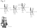
- Fig. 2 shows an example of a case of performing operation for obtaining exterior orientation parameters, or location and attitude, of the surveying device 400 by using the target device 100.
- Fig. 2 shows the surveying device 400 and multiple target devices 100 located around the surveying device 400. In this case, four target devices 100 are located.
- Fig. 2 shows an example of a situation in which an operator 110 carries the target device 100 while holding it in the hand and locates the target device 100 at a planned point while supporting it, and then the target device 100 is positioned.
- the surveying device 400 may be configured to stand by itself, and the surveying device 400 may be made to stand by itself at the located point.
- the located point of the target device 100 is determined in advance in this embodiment, the located point may be determined at site.
- Fig. 2 shows four target devices 100 as an example.
- the four target devices 100 may be set at the same time and may be positioned by the surveying device 400.
- one target device 100 may be used at four positions, and the four positions may be positioned successively.
- two target devices 100 may be used at two respective positions, and a total of four positions may be set.
- To obtain the exterior orientation parameters of the surveying device 400 at least three positioning points are required. Normally, at least three points, or many points as much as possible, are used as the positioning points or control points to calculate the exterior orientation parameters of the surveying device 400.
- the surveying device 400 has a TS functional part 200 and a laser scanner part 300 that are combined.
- the TS functional part 200 functions as a total station.
- the laser scanner part 300 functions as a laser scanner.
- the TS functional part 200 exhibits a function as a total station (TS). Details of the TS are disclosed in Japanese Unexamined Patent Applications Laid-Open Nos. 2009-229192 and 2012-202821 , for example.
- the laser scanner part 300 performs laser scanning to obtain three-dimensional point cloud data, which is hereinafter called "point cloud data".
- point cloud data The technique relating to the laser scanner is disclosed in Japanese Unexamined Patent Applications Laid-Open Nos. 2010-151682 and 2008-268004 and in U.S. Patent No. 8767190 , for example.
- a laser scanner that scans electronically can also be used.
- Such a laser scanner is disclosed in U.S. Patent Application Publication No. 2015/0293224 , for example.
- the laser scanner part 300 performs laser scanning in a direction of an angle of elevation or depression along a vertical plane containing an optical axis of distance measuring light of the TS functional part 200.
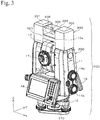
- the vertical plane is a Y-Z plane shown in Fig. 3 .
- the laser scanning is performed along the vertical plane while a horizontally rotating unit 11 is rotated horizontally, whereby laser scanning is performed at the circumference by 360 degrees including the above direction.
- the point cloud data that is obtained by the laser scanner part 300 has a local coordinate system having an origin at the surveying device 400.
- the position of the origin of the local coordinate system is preliminarily selected due to it being constant regardless of rotation of the horizontally rotating unit 11 and a vertically rotating unit 13.
- Point cloud data in an absolute coordinate system is obtained on the condition that the exterior orientation parameters, or location and attitude, in the absolute coordinate system, of the surveying device 400 are determined.
- the absolute coordinate system is, for example, a coordinate system used in a GNSS.
- the absolute coordinate system describes a location in terms of longitude, latitude, and altitude above mean sea level.
- the surveying device 400 includes the horizontally rotating unit 11.
- the horizontally rotating unit 11 is held on a base 12 in a horizontally rotatable state.
- the base 12 is fixed on a top of a tripod (not shown).
- the horizontally rotating unit 11 has an approximately U shape and has two extending parts that upwardly extend, and the vertically rotating unit 13 is held between the two extending parts so as to be controllable in angle of elevation, which includes elevation angle and depression angle.
- the horizontally rotating unit 11 rotates horizontally relative to the base 12 by electrical operation.
- the vertically rotating unit 13 rotates in the vertical plane by electrical operation.
- the horizontally rotating unit 11 has a horizontal rotation angle controlling dial 14a and an elevation and depression angle controlling dial 14b that are arranged thereon.
- the horizontal rotation angle controlling dial 14a is operated to adjust a horizontal rotation angle of the horizontally rotating unit 11.
- the elevation and depression angle controlling dial 14b is operated to adjust the angle of elevation, which includes the elevation angle and the depression angle, in the vertical plane, of the vertically rotating unit 13.
- the vertically rotating unit 13 has a sighting unit 15a for approximate sighting, arranged on a top thereof.
- the vertically rotating unit 13 also has an optical sighting unit 15b with a visual field narrower than that of the sighting unit 15a and has a telescope 16 that can be collimated at a higher accuracy.
- the vertically rotating unit 13 contains an optical system that conducts an image captured by the sighting unit 15b and the telescope 16, to an eyepiece 17.
- the image that is captured by the sighting unit 15b and the telescope 16 is visually recognized by looking into the eyepiece 17.
- the vertically rotating unit 13 houses a camera and an optical system that guides an image captured by the telescope 16, to the camera.
- the image that is captured by the telescope 16 can be imaged by the camera.
- the telescope 16 also serves as an optical system for distance measuring laser light and for tracking light.
- the tracking light is used to track and capture an object to which a distance is to be measured.
- the object is the entire circumference reflection prism 102.
- the optical system is designed so that optical axes of the distance measuring light and the tracking light will coincide with an optical axis of the telescope 16.
- the structure of this part is the same as that of a commercially available TS.
- the horizontally rotating unit 11 has displays 18 and 19 mounted thereto.
- the display 18 is integrated with a controller 210.
- the controller 210 has a numeric keypad, a cross operation button, and other operation parts arranged thereon, which are used to perform various operations relating to the surveying device 400 and are used to input data.
- the displays 18 and 19 display various information necessary to operate the surveying device 400, display surveying data, and display other information. These two displays are mounted in order to enable viewing the display from either a front side or a back side without having to rotate the horizontally rotating unit 11.
- the horizontally rotating unit 11 has the laser scanner part 300 that is fixed on a top.
- the laser scanner part 300 has a first column 301 and a second column 302.
- the first column 301 and the second column 302 are connected by a connecting part 303.
- the space over the connecting part 303 between the first column 301 and the second column 302 is covered with a protective case 304.
- the protective case 304 is made of a member that transmits scanning laser light.
- the protective case 304 houses a columnar rotating part 305 that protrudes from the first column 301 in a horizontal direction.
- a tip of the rotating part 305 is obliquely cut off, and this tip has a tilt mirror 306 fixed thereon.
- the rotating part 305 is driven to be rotated around an extending direction thereof, which is the horizontal direction, by a motor contained in the first column 301.
- the first column 301 contains, in addition to the motor, a driving circuit for driving the motor, a control circuit for the driving circuit, a sensor for measuring a rotation angle of the rotating part 305, and a peripheral circuit of the sensor.
- the second column 302 contains a light emitting part for emitting laser scanning light, a light receiving part that receives the laser scanning light reflected back from an object, an optical system for the light emitting part and the light receiving part, and a distance calculator that calculates a distance to a laser scanned point.
- a three-dimensional location of the laser scanned point is calculated on the basis of a rotation angle of the rotating part 305, a horizontal rotation angle of the horizontally rotating unit 11, and a distance to the laser scanned point.
- the three-dimensional location of the laser scanned point is calculated by the laser scanner part 300 or a laser scanning controlling unit 501 that is disposed in the horizontally rotating unit 11.
- the laser scanning controlling unit 501 is shown in Fig. 5 .
- the laser scanning light is composed of one beam.
- the laser scanning light is emitted from the inside of the second column 302 to the tilt mirror 306 and is reflected thereat to exit to the outside via the transparent protective case 304.
- the laser scanning light is emitted from the light emitting part by means of pulse emission at a repetition frequency of several kHz to several hundreds of kHz.
- the emitted pulsed light advances in the horizontal direction to the tilt mirror 306 at the tip of the rotating part 305 that is rotating, and this light is reflected thereat at a right angle.
- the laser scanning light is radially and sporadically emitted by means of pulse irradiation, to scan along a vertical plane containing the optical axis of the telescope 16 in the direction of the angle of elevation or depression.
- the laser scanning is performed in the vertical plane containing an optical axis of the TS functional part 200, and more exactly, the optical axis of the telescope 16.
- the optical axis of the TS functional part 200 is on a Y-axis
- the laser scanning is performed while the horizontally rotating unit 11 is horizontally rotated, whereby three-dimensional laser scanning is performed on a necessary area.
- the scanning light that is reflected back from an object reverses the path of the emitted light and is received by the light receiving part in the second column 302.
- the laser scanned point that is, the point that reflects the scanning light, is positioned by referring to light emission timing and light reception timing of the scanning light as well as the angle of the rotating part 305 and the horizontal rotation angle of the horizontally rotating unit 11 at each of these timings.
- the angle of the rotating part 305 is elevation or depression. The principle of the positioning is the same as that for normal laser distance measurement.
- the positioning is performed to each of many scanned points, whereby three-dimensional coordinates of each of the scanned points are obtained.
- the obtained three-dimensional coordinates of each of the scanned points form point cloud data.
- the density of the scanned points to be scanned is adjusted by varying an oscillation frequency or a pulse interval of the scanning laser light, a rotation speed of the horizontally rotating unit 11, or a rotation speed of the rotating part 305.
- the surveying device 400 includes the processing unit 500 shown in Fig. 5 .
- the processing unit 500 performs various kinds of processing relating to the surveying device 400.
- the processing unit 500 functions as a computer and is constituted of a microcomputer and various kinds of electronic circuits.
- the processing unit 500 includes the laser scanning controlling unit 501, a point cloud data obtaining unit 502, a code-display detection determining unit 503, a prism-induced reflected light determining unit 504, a decoding unit 505, a decoded data obtaining unit 506, a distance calculator 507, a scan interval calculator 508, a relationship determining unit 509, a scanning density adjuster 510, and a TS function controlling unit 511.
- the distance calculator 507 calculates a distance "L” to the code display on the basis of point cloud data.
- the scan interval calculator 508 calculates a scan interval "D" in scanning the code display on the basis of the distance "L” to the code display.
- the relationship determining unit 509 determines a relationship between a minimum distance "d" of display patterns of the code display and the scan interval "D".
- the laser scanning controlling unit 501 performs controlling and processing that relate to obtaining of the point cloud data by the laser scanner part 300.
- data of three-dimensional coordinates of each of points that reflect the scanning laser light and data of intensity of reflected light are obtained as point cloud data.
- the point cloud data obtaining unit 502 receives the point cloud data obtained by the laser scanner part 300.
- the code-display detection determining unit 503 determines a condition of detecting bar code information of the entire circumference bar code display part 103 on the basis of the data of intensity of the reflected light, which is included in the point cloud data. For example, it is determined that 30 % of the bar code information is successfully decoded, 50 % of the bar code information is successfully decoded, or 100 % of the bar code information is successfully decoded.
- the prism-induced reflected light determining unit 504 determines whether the point cloud data includes data based on the reflected light that is reflected back from the entire circumference reflection prism 102.
- the entire circumference reflection prism 102 is formed by using a mirror surface and reflects the laser scanning light at a high reflection efficiency. Thus, the intensity of the reflected light that is reflected back from the entire circumference reflection prism 102 is highest. This phenomenon is used to detect the reflected light that is reflected back from the entire circumference reflection prism 102.
- the intensity of the detected light is determined by using a threshold. In this case, light with an intensity exceeding a specific threshold is detected as the reflected light that is reflected back from the entire circumference reflection prism 102. In another example, a saturated condition of a light-receiving element of the laser scanner is detected to recognize detection of the reflected light that is reflected back from the entire circumference reflection prism 102.
- the light-receiving element fails to accept properly upon receiving light with an intensity exceeding input resistance and is saturated, whereby correct characteristics are not obtained.
- the output is continuously saturated, for example, an abnormal value is continuously output, and correct light detection is difficult to perform. Detecting this phenomenon enables determination of reception of the reflected light that is reflected back from the entire circumference reflection prism 102.
- the decoding unit 505 decodes the bar code information of the entire circumference bar code display part 103 on the basis of information of a reflection intensity, which is included in the point cloud data. Then, the decoding unit 505 reads identification information of the entire circumference bar code display part 103 or identification information of the target device 100 from the decoded bar code information.
- the bar code is decoded by reading intensity variation of the reflected light of the scanning light. This is the same as that in the case of decoding an ordinary bar code.
- the decoded data obtaining unit 506 obtains the code information of the entire circumference bar code display part 103, which is decoded by the decoding unit 505, that is, the identification information of the target device 100.
- the distance calculator 507 calculates a distance "L" from the surveying device 400 to a reflection surface of the entire circumference bar code display part 103 on the basis of the reflected light that is reflected back from the entire circumference bar code display part 103.
- the scan interval calculator 508 calculates a scan interval "D", which is a distance between adjacent scanned points, at an area containing the point that is used to calculate the distance "L". This calculation is performed as follows. First, an open angle ⁇ between adjacent optical axes of the scanning pulsed light in the vertical direction or an up-down direction at the time of obtaining the point is obtained from the scanning condition.
- the radius "L” is calculated as the distance “L” by the distance calculator 507, and the central angle ⁇ is obtained from the scanning condition.
- the scan interval "D" is calculated by using the relational expression described above.
- a light emission frequency of the scanning laser light is 50 kHz
- the number of rotations of the rotating part 305 is 5 times per second
- the distance "L" is 50 meters.
- the number of pulses per one rotation is 10000
- ⁇ 2 ⁇ /10000.
- D (2 ⁇ /10000) ⁇ 50 ⁇ 3 cm.
- the relationship determining unit 509 determines whether the minimum interval "d" of the display patterns of the code display and the scan interval "D" have a relationship that allows an appropriate reading of the bar code display of the entire circumference bar code display part 103.
- a relationship d > D is set to reliably make the bar or the interval of the bars irradiated with the scanning light, thereby enabling obtaining reflected light that is reflected back from every part of the bar code display of the entire circumference bar code display part 103.
- the scanning density adjuster 510 adjusts the conditions of the laser scanning so that the relationship d > D will be obtained.
- the TS functional part controlling unit 511 controls movement of the TS functional part 200 of the surveying device 400. This movement control is the same as that for a commercially available TS.
- the exterior orientation parameters of the surveying device 400 are obtained in order to obtain point cloud data by means of laser scanning using the laser scanning function of the surveying device 400. Obtaining the exterior orientation parameters of the surveying device 400 in the absolute coordinate system enables obtaining three-dimensional point cloud data in the absolute coordinate system by means of the laser scanning.
- laser scanning is performed from multiple points of view in order to eliminate blindspots or occlusions.
- exterior orientation parameters of the located position of the surveying device 400 viewed from each point are obtained in the absolute coordinate system
- three-dimensional point cloud data that are obtained at the respective points of view are easy to consolidate in the same coordinate system or in the absolute coordinate system.
- a process for mutually matching three-dimensional point cloud data that are obtained at different points of view is a large burden on processing, and margin of error in data and calculation error should be taken into consideration.
- three-dimensional point cloud data in the same coordinate system enables avoiding these problems even though the three-dimensional point cloud data are obtained from different points of view.
- This technique requires obtaining exterior orientation parameters of a laser scanner in the absolute coordinate system with respect to each of multiple points of view. In the case of this embodiment, it is necessary to obtain exterior orientation parameters of the surveying device 400. The exterior orientation parameters are obtained in accordance with the processing shown in Fig. 6 .
- the exterior orientation parameters of the surveying device 400 are obtained by using the target device 100.
- This processing is performed as follows. (1) First, the surveying device 400 is located. At this stage, the location and the attitude of the surveying device 400 are unknown. (2) The target device 100 is located. (3) The location of the target device 100 is obtained by relative positioning using a GNSS. (4) The target device 100 is positioned by using the TS function of the surveying device 400.
- the location of the target device 100 is changed, these work steps are repeated to obtain multiple control points or orienting points, in which locations are determined, around the surveying device 400.
- the location and the attitude, that is, the exterior orientation parameters, of the surveying device 400 in the absolute coordinate system are determined by a method of resection.
- the method of resection is disclosed in, for example, Japanese Unexamined Patent Application Laid-Open No. 2013-186816 .
- the surveying device 400 may be used for each kind of surveying using laser scanning and the functions of the TS.
- the laser scanning function of the laser scanner part 300 for obtaining point cloud data is used to capture the target device 100 and read the code information. The following describes an example of this processing.
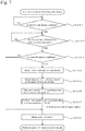
- Fig. 6 is a flowchart showing a processing procedure for capturing the target device 100.
- Fig. 7 is a flowchart showing details of step S104 in Fig. 6 .
- Programs for executing the processing in Figs. 6 and 7 are stored in an appropriate storage area and are executed by the processing unit 500 shown in Fig. 5 . It is also possible to store these programs in an external storage medium.
- the surveying device 400 is located at a position appropriate for laser scanning (step S101).
- the located position is roughly determined in advance or may be determined at the site.
- the target device 100 is located at each of multiple positions that can be viewed from the surveying device 400 (step S102).
- FIG. 2 An example of this situation is shown in Fig. 2 .
- the operator 110 carries the target device 100 by hand and locates the target device 100 at a predetermined position that serves as a control point. At this time, the position at which the target device 100 is located is determined in advance, and this position is displayed on the terminal 105 held by the operator 110 to guide the operator 110.
- laser scanning is performed to the surroundings of the surveying device 400 by using the laser scanning function of the surveying device 400 (step S103). This process is performed by the laser scanning controlling unit 501. It is possible to perform this laser scanning while limiting the area to be scanned. The area to be scanned is set so that all of the multiple target devices 100 located around the surveying device 400 will be scanned.
- step S103 point cloud data or laser scanning data of the surroundings of the surveying device 400 is obtained.
- This point cloud data is received by the point cloud data obtaining unit 502.
- the direction of the laser scanning is set to cause the scanning to be performed from above to below. The reason for this is to make the scanning light first hit the entire circumference bar code display part 103 and then hit the entire circumference reflection prism 102.
- the reflectance of the entire circumference reflection prism 102 is set higher than that of a reflection surface of the bar code display of the entire circumference bar code display part 103.
- the entire circumference reflection prism 102 and the entire circumference bar code display part 103 are arranged on a vertical line.
- the entire circumference reflection prism 102 reflects laser scanning light at high intensity due to the high reflectance, and the reflected light may saturate the light-receiving element of the laser scanner part 300 depending on conditions. It is also possible to set the conditions so that the saturation will occur as desired. Once the light-receiving element is saturated, the saturated condition continues for some time, resulting in failure in subsequent detection of the scanning light that is reflected back. If this phenomenon occurs at the time the scanning light hits the entire circumference bar code display part 103, the bar code information is difficult to detect. To avoid this problem, it is configured that the scanning light first hits the entire circumference bar code display part 103 and then hits the entire circumference reflection prism 102.
- a process for detecting the entire circumference bar code display part 103 is performed on the basis of the point cloud data or the laser scanning data (step S104). Details of this process are shown in Fig. 7 .
- the process shown in Fig. 7 is performed in parallel with obtaining the point cloud data.
- the process shown in Fig. 7 may be performed after all or most of the point cloud data are obtained.
- step S201 it is determined whether at least a part of the bar code display of the entire circumference bar code display part 103 is detected. This step of the process is performed by the code-display detection determining unit 503.
- step S201 (1) whether reflected light that is reflected back from the reflection surface constituting the bar code display of the entire circumference bar code display part 103 is detected is determined by using a threshold, and furthermore, (2) whether the reflected light exists at two or more points in the vertical direction is determined. If the two determinations are YES, the determination in step S201 is YES.
- step S201 it is determined whether reflected light that is reflected back from the reflection prism 102 is obtained on the same vertical line as the reflected light that is reflected back from the reflection surface, which is used in the determination (1) (step S202). This step of the process is performed by the prism-induced reflected light determining unit 504.
- step S203 it is determined whether the code information or the bar code information of the entire circumference bar code display part 103, which is obtained in step S201, is insufficient, that is, whether the bar code information of the entire circumference bar code display part 103 is appropriately decoded. This step of the process is performed by the decoding unit 505.
- step S203 As a result of the determination in step S203, if the code information is sufficient, and the entire circumference bar code display part 103 is identifiable, the process advances to step S208.
- step S208 the corresponding bar code information is obtained. This step of the process is performed by the decoded data obtaining unit 506.
- step S204 point cloud data based on the reflected light that is reflected back from the entire circumference bar code display part 103 is obtained.
- This entire circumference bar code display part 103 is subjected to the determination in step S201 or S203. That is, point cloud data of the entire circumference bar code display part 103 is obtained in step S204.
- a distance "L" from the surveying device 400 to the entire circumference bar code display part 103 is calculated on the basis of the obtained point cloud data (step S205).
- This step of the process is performed by using a principle that the point cloud data is based on data of distance to scanned points.
- This step of the process is performed by the distance calculator 507.
- a scan interval "D" between the laser scanned points at a part of the entire circumference bar code display part 103 is calculated on the basis of the distance "L" obtained in step S205 (step S206).
- the scan interval "D” is an interval between adjacent scanned points in the scanning direction or the vertical direction of the target entire circumference bar code display part 103.
- the process in step S206 is performed by the scan interval calculator 508.
- the laser scanning is performed again in the condition in which the laser scanning condition is changed so that D ⁇ d will be obtained (step S207). This other laser scanning is performed to the vertical line in which the entire circumference bar code display part 103 extends.
- the laser scanning condition is changed as described above by increasing a pulse frequency of the scanning light or decreasing the rotation speed of the rotating part 305, or both.
- step S207 After the other laser scanning is performed in step S207, point cloud data that is obtained by this laser scanning is acquired. Then, the bar code display of the entire circumference bar code display part 103 is read from the degree of intensity of the reflected light that is reflected back from each of the points (step S208).
- step S104 in Fig. 6 is performed by these steps described above.
- step S104 the process advances to step S105.
- step S105 the direction of the entire circumference reflection prism 102 that is detected in step S202, as viewed from the surveying device 400, is obtained.
- step S 106 If there is any undetected target device 100 among the preliminarily registered target devices 100, the determination in step S 106 is YES, and the process in step S104 and in subsequent steps is repeated. Thus, the identification information and the direction of the multiple target devices 100 as viewed from the surveying device 400 are obtained.
- the processing for obtaining the exterior orientation parameters of the surveying device 400 is briefly described hereinafter.
- the location in the absolute coordinate system of each of the target devices 100 is obtained by relative positioning using the GNSS unit 104.
- the entire circumference reflection prism 102 is positioned precisely by using the function of the TS of the surveying device 400.
- the direction of the target device 100 as viewed from the surveying device 400 is known, and therefore, the positioning of the target device 100 using the TS function is automatically smoothly performed.
- the positioning data of the entire circumference reflection prism 102 based on the laser scanning information, which is obtained in step S202.
- the exterior orientation parameters of the surveying device 400 is calculated by a method of resection on the basis of a directional line that connects each of the target devices 100 and the surveying device 400, as well as the location of each of the target devices 100 in the absolute coordinate system.
- the searching for and identifying a target using the laser scanning are automatically performed, thereby eliminating the need for an operator to perform the sighting. This simplifies the work for sighting and identifying the target.
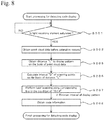
- the light-receiving element of the laser scanner is saturated by the highly intensive reflected light that is reflected back from the entire circumference reflection prism 102. This phenomenon can be used in reading the code information of the entire circumference bar code display part 103 by means of the laser scanning that is performed again. An embodiment of this case is described hereinafter.
- Fig. 8 shows an example of a processing procedure.
- the scanning method and the process in step S205 and in subsequent steps are the same as in the case shown in Fig. 7 .
- the pieces of hardware are the same as those used in First Embodiment.
- step S301 it is determined whether the light-receiving element of the light receiving part of the laser scanner part 300 is saturated in response to reception of the laser scanning light that is reflected back (step S301).
- the light-receiving element is saturated, output of the light-receiving element is distorted, and output characteristics representing the saturation of the element are shown.
- a photodiode is used as the light-receiving element.
- output includes an abnormal value, and the influence of the saturation remains for some time. Due to this, subsequent detection of some points or subsequent detection of the laser scanning light fails, and point clouds are missing. After a specific time has passed, the performance of the photodiode recovers. When this phenomenon occurs, the light-receiving element or the photodiode is determined as being saturated.
- step S302 point cloud data is obtained that is obtained immediately before the light-receiving element is saturated.
- the number of points in the point cloud data to be obtained is from several points to several tens of points.
- the laser scanning is performed along the vertical plane from above to below.
- the laser scanning light first hits the entire circumference bar code display part 103 and then hits the entire circumference reflection prism 102.
- a point cloud that is obtained immediately before the detection can be considered as a point cloud that is obtained from the entire circumference bar code display part 103.
- This function is used to obtain the point cloud data of the entire circumference bar code display part 103.
- step S205 and in subsequent steps after the point cloud data of the entire circumference bar code display part 103 is obtained is the same as that in the case shown in Fig. 7 .
- a simple process for increasing the scanning density may be performed.
- the scanning condition may be changed so that the scanning density is double, and then, the scanning is performed again.
- the process in Fig. 7 may be performed without steps S201 and S203.
- the laser scanning for detecting the entire circumference bar code display part 103 is performed again.
- Some degree of tilt of the target device 100 is allowable.
- the tilt is allowable on the condition that the laser scanning in the longitudinal direction of the entire circumference bar code display part 103 can be performed.
- the target device 100 is further provided with a clinometer and an azimuth meter, and positioning data of the target device 100 obtained by the surveying device 400 is corrected. This technique is described below.
- a horizontal position such as longitude and latitude
- the entire circumference reflection prism 102 differs from a horizontal position of the bottom end 101a of the support member 101. This difference generates measurement error in the positioning data of the target device 100.
- the difference between the horizontal positions or the measurement error in the horizontal position can be calculated in the condition that the direction and the degree of the tilt of the target device 100 are known.
- data of the clinometer and the azimuth meter of the target device 100 are used to quantitatively calculate the tilt of the target device 100, and the result is used to correct the positioning data of the target device 100.
- the positioning of the target device 100 may be performed by another total station (TS) that is separated from the surveying device 400 and that the exterior orientation parameters are known.
- TS total station
Claims (5)
- Procédé d'arpentage utilisant un dispositif d'arpentage (400) pour détecter et identifier un dispositif cible (100) qui comprend un prisme de réflexion de circonférence entière (102) et un affichage de code à barres de circonférence entière (103), ledit affichage de code à barres de circonférence entière (103) comprenant une pluralité de barres circulaires qui s'étendent dans une direction circonférentielle tout en étant disposées dans une direction verticale, ledit dispositif d'arpentage (400) ayant un scanner laser (300) configuré pour effectuer un balayage laser de telle manière que de la lumière laser pulsée soit émise et déplacée le long d'une direction verticale tandis que le scanner laser (300) tourne horizontalement, le procédé d'arpentage comprenant:effectuer le balayage laser; etdétecter l'affichage de code à barres de circonférence entière (103) sur la base de la lumière laser pulsée qui est réfléchie en retour,dans lequel une réflectance du prisme de réflexion de circonférence entière (102) est supérieure à la réflectance de l'affichage de code à barres de circonférence entière (103), etla lumière laser pulsée frappe d'abord l'affichage de code à barres de circonférence entière (103) et puis frappe le prisme de réflexion de circonférence entière (102) lorsque la lumière laser pulsée est déplacée le long de la direction verticale dans le balayage laser.
- Procédé d'arpentage selon la revendication 1, dans lequel le prisme de réflexion de circonférence entière (102) et l'affichage de code à barres de circonférence entière (103) sont disposées sur la même ligne verticale.
- Procédé d'arpentage selon la revendication 2, comprenant en outre:
détecter le prisme de réflexion de circonférence entière (102) ou l'affichage de code à barres de circonférence entière (103), ou les deux, sur la base de l'intensité de la lumière de balayage laser qui est réfléchie en retour; et,
après que la détection du prisme de réflexion de circonférence entière (102) ou de l'affichage de code à barres de circonférence entière (103), ou des deux, a été effectuée, effectuer un nouveau balayage laser par rapport à l'affichage de code à barres de circonférence entière (103) dans la condition dans laquelle une densité de balayage est modifiée de manière à être supérieure à une densité de balayage précédente. - Procédé d'arpentage selon la revendication 1, dans lequel, dans un cas dans lequel un élément récepteur de lumière destiné à recevoir la lumière de balayage laser qui est réfléchie en retour est saturé, des données de nuage de points qui sont obtenues avant que la saturation ne se produise sont obtenues en tant que données de nuage de points de l'affichage de code à barres de circonférence entière (103).
- Support d'enregistrement informatique non volatile stockant des instructions exécutables par ordinateur pour commander le fonctionnement d'un dispositif d'arpentage (400), ledit dispositif d'arpentage (400) ayant un scanner laser (300) et étant adapté pour détecter et identifier un dispositif cible (100) ayant un prisme de réflexion de circonférence entière (102) et un affichage de code à barres de circonférence entière (103), l'affichage de code à barres de circonférence entière comprenant une pluralité de barres circulaires qui s'étendent dans une direction circonférentielle tout en étant disposées dans une direction verticale, et une réflectance du prisme de réflexion de circonférence entière étant supérieure à la réflectance de l'affichage de code à barres de circonférence entière, les instructions exécutables par ordinateur étant faites pour, lorsqu'elles sont exécutées par une unité de traitement (500) du dispositif d'arpentage, amener le dispositif d'arpentage à:effectuer un balayage laser de telle manière que de la lumière laser pulsée soit émise et déplacée le long d'une direction verticale tandis que le scanner laser tourne horizontalement, et que la lumière laser pulsée frappe d'abord l'affichage de code à barres de circonférence entière et puis frappe le prisme de réflexion de circonférence entière lorsque la lumière laser pulsée est déplacée le long de la direction verticale dans le balayage laser; etdétecter l'affichage de code à barres de circonférence entière sur la base de la lumière laser pulsée qui est réfléchie en retour, tout en utilisant ladite différence de réflectance et l'ordre dans lequel la lumière laser pulsée frappe l'affichage de code à barres de circonférence entière et le prisme de réflexion de circonférence entière.
Applications Claiming Priority (1)
| Application Number | Priority Date | Filing Date | Title |
|---|---|---|---|
| JP2018129143A JP7163085B2 (ja) | 2018-07-06 | 2018-07-06 | 測量方法、測量装置およびプログラム |
Publications (2)
| Publication Number | Publication Date |
|---|---|
| EP3591336A1 EP3591336A1 (fr) | 2020-01-08 |
| EP3591336B1 true EP3591336B1 (fr) | 2021-05-26 |
Family
ID=66826893
Family Applications (1)
| Application Number | Title | Priority Date | Filing Date |
|---|---|---|---|
| EP19179635.8A Active EP3591336B1 (fr) | 2018-07-06 | 2019-06-12 | Procédé et programme d'arpentage |
Country Status (4)
| Country | Link |
|---|---|
| US (1) | US11592291B2 (fr) |
| EP (1) | EP3591336B1 (fr) |
| JP (1) | JP7163085B2 (fr) |
| CN (1) | CN110686661B (fr) |
Families Citing this family (11)
| Publication number | Priority date | Publication date | Assignee | Title |
|---|---|---|---|---|
| EP3819591A1 (fr) * | 2019-11-08 | 2021-05-12 | Trimble Jena GmbH | Instrument de surveillance optique |
| CN111707229B (zh) * | 2020-06-23 | 2022-03-29 | 湖北三江航天万峰科技发展有限公司 | 一种定位定向设备的直角棱镜俯仰和方位角测量调节方法 |
| CN111750842B (zh) * | 2020-07-10 | 2024-03-15 | 中铁第四勘察设计院集团有限公司 | 用于摄影测量的反射片及采用其进行全站仪自动照准方法 |
| CN111929644B (zh) * | 2020-08-19 | 2023-12-26 | 成都清正公路工程试验检测有限公司 | 一种基于激光扫描的测点定位方法 |
| CN111928831B (zh) * | 2020-08-21 | 2022-09-13 | 重庆德生鼎盛实业发展有限公司 | 一种可提高精准度的水利施工用桩位测量定点摆放装置 |
| JP2022050943A (ja) * | 2020-09-18 | 2022-03-31 | 株式会社トプコン | ターゲットの方向取得装置、制御システム、測量装置をターゲットの方向に指向させる方法およびプログラム。 |
| JP7464558B2 (ja) * | 2021-03-29 | 2024-04-09 | 株式会社トプコン | 測量データ処理装置、測量データ処理方法および測量データ処理用プログラム |
| JP2022188482A (ja) * | 2021-06-09 | 2022-12-21 | 株式会社トプコン | データ処理装置、データ処理方法およびデータ処理用プログラム |
| JP2023137353A (ja) | 2022-03-18 | 2023-09-29 | 株式会社トプコン | 測量装置、測量方法および測量用プログラム |
| JP2023150501A (ja) | 2022-03-31 | 2023-10-16 | 株式会社トプコン | 測量装置、測量方法および測量用プログラム。 |
| US20230351541A1 (en) * | 2022-04-29 | 2023-11-02 | Trimble Inc. | Correcting position of a mobile device using a mobile reference |
Family Cites Families (14)
| Publication number | Priority date | Publication date | Assignee | Title |
|---|---|---|---|---|
| US5076690A (en) * | 1990-05-14 | 1991-12-31 | Spectra-Physics Laserplane, Inc. | Computer aided positioning system and method |
| JPH09105628A (ja) * | 1995-10-12 | 1997-04-22 | Hakko Denki Kk | 自走台車の位置特定方法と、その装置 |
| EP1329690A1 (fr) | 2002-01-22 | 2003-07-23 | Leica Geosystems AG | Procédé et dispositif pour la localisation automatique de cibles |
| JP5263804B2 (ja) | 2007-04-20 | 2013-08-14 | 株式会社トプコン | 多点測定方法及び測量装置 |
| JP5212856B2 (ja) | 2007-05-16 | 2013-06-19 | 国際航業株式会社 | 測量システムおよび測量方法 |
| JP5124319B2 (ja) | 2008-03-21 | 2013-01-23 | 株式会社トプコン | 測量機、測量システム、測定対象の検出方法、および測定対象の検出プログラム |
| JP5688876B2 (ja) | 2008-12-25 | 2015-03-25 | 株式会社トプコン | レーザスキャナ測定システムの較正方法 |
| EP3901653A3 (fr) | 2010-05-17 | 2022-03-02 | Velodyne Lidar USA, Inc. | Système lidar haute définition |
| JP5725922B2 (ja) | 2011-03-25 | 2015-05-27 | 株式会社トプコン | 測量システム及びこの測量システムに用いる測量用ポール及びこの測量システムに用いる携帯型無線送受信装置 |
| JP5832341B2 (ja) | 2012-03-09 | 2015-12-16 | 株式会社トプコン | 動画処理装置、動画処理方法および動画処理用のプログラム |
| US10132928B2 (en) | 2013-05-09 | 2018-11-20 | Quanergy Systems, Inc. | Solid state optical phased array lidar and method of using same |
| KR102124930B1 (ko) * | 2013-08-16 | 2020-06-19 | 엘지전자 주식회사 | 공간 해상도가 가변되는 거리 정보를 획득할 수 있는 거리검출장치 |
| JP6438311B2 (ja) | 2015-01-27 | 2018-12-12 | 株式会社トプコン | 測量システム、測量方法、測量機及び測量用反射ターゲット |
| JP6749191B2 (ja) | 2016-09-21 | 2020-09-02 | 株式会社トプコン | スキャナ装置および測量装置 |
-
2018
- 2018-07-06 JP JP2018129143A patent/JP7163085B2/ja active Active
-
2019
- 2019-06-12 EP EP19179635.8A patent/EP3591336B1/fr active Active
- 2019-06-17 US US16/442,616 patent/US11592291B2/en active Active
- 2019-07-05 CN CN201910603202.8A patent/CN110686661B/zh active Active
Also Published As
| Publication number | Publication date |
|---|---|
| EP3591336A1 (fr) | 2020-01-08 |
| CN110686661A (zh) | 2020-01-14 |
| JP7163085B2 (ja) | 2022-10-31 |
| CN110686661B (zh) | 2023-06-30 |
| JP2020008406A (ja) | 2020-01-16 |
| US11592291B2 (en) | 2023-02-28 |
| US20200011664A1 (en) | 2020-01-09 |
Similar Documents
| Publication | Publication Date | Title |
|---|---|---|
| EP3591336B1 (fr) | Procédé et programme d'arpentage | |
| US7321420B2 (en) | Survey system | |
| US9581442B2 (en) | Surveying instrument | |
| US9316496B2 (en) | Position determination method and geodetic measuring system | |
| US10895632B2 (en) | Surveying system | |
| EP3514489B1 (fr) | Dispositif et procédé de surveillance | |
| EP3483554A1 (fr) | Dispositif de surveillance et procédé de vérification d'étalonnage et programme de vérification d'étalonnage pour dispositif de surveillance | |
| EP3767231A1 (fr) | Appareil de surveillance | |
| US11725938B2 (en) | Surveying apparatus, surveying method, and surveying program | |
| US9618340B2 (en) | Surveying instrument | |
| EP2788715B1 (fr) | Mise à niveau robotique | |
| US20210302162A1 (en) | Surveying Instrument And Surveying System | |
| US20170160108A1 (en) | Angle Detecting Device And Surveying Instrument | |
| US20160102977A1 (en) | Surveying Instrument | |
| EP3812795B1 (fr) | Système et procédé de scanner | |
| JP7289252B2 (ja) | スキャナシステムおよびスキャン方法 | |
| WO2024071287A1 (fr) | Miroir polygonal à anneau de torsion, émetteur de lumière, et système d'arpentage | |
| US11859977B2 (en) | Surveying device, surveying method, and surveying program | |
| JP2023100945A (ja) | 測量装置、測量方法および測量用プログラム |
Legal Events
| Date | Code | Title | Description |
|---|---|---|---|
| PUAI | Public reference made under article 153(3) epc to a published international application that has entered the european phase |
Free format text: ORIGINAL CODE: 0009012 |
|
| STAA | Information on the status of an ep patent application or granted ep patent |
Free format text: STATUS: THE APPLICATION HAS BEEN PUBLISHED |
|
| AK | Designated contracting states |
Kind code of ref document: A1 Designated state(s): AL AT BE BG CH CY CZ DE DK EE ES FI FR GB GR HR HU IE IS IT LI LT LU LV MC MK MT NL NO PL PT RO RS SE SI SK SM TR |
|
| AX | Request for extension of the european patent |
Extension state: BA ME |
|
| STAA | Information on the status of an ep patent application or granted ep patent |
Free format text: STATUS: REQUEST FOR EXAMINATION WAS MADE |
|
| 17P | Request for examination filed |
Effective date: 20200708 |
|
| RBV | Designated contracting states (corrected) |
Designated state(s): AL AT BE BG CH CY CZ DE DK EE ES FI FR GB GR HR HU IE IS IT LI LT LU LV MC MK MT NL NO PL PT RO RS SE SI SK SM TR |
|
| GRAP | Despatch of communication of intention to grant a patent |
Free format text: ORIGINAL CODE: EPIDOSNIGR1 |
|
| STAA | Information on the status of an ep patent application or granted ep patent |
Free format text: STATUS: GRANT OF PATENT IS INTENDED |
|
| RIC1 | Information provided on ipc code assigned before grant |
Ipc: G01C 15/06 20060101ALI20201118BHEP Ipc: G01S 17/42 20060101ALI20201118BHEP Ipc: G01S 7/481 20060101ALI20201118BHEP Ipc: G01C 15/00 20060101AFI20201118BHEP Ipc: G01S 17/66 20060101ALI20201118BHEP |
|
| INTG | Intention to grant announced |
Effective date: 20201223 |
|
| RAP1 | Party data changed (applicant data changed or rights of an application transferred) |
Owner name: TOPCON CORPORATION |
|
| RIN1 | Information on inventor provided before grant (corrected) |
Inventor name: SASAKI, YOU |
|
| GRAS | Grant fee paid |
Free format text: ORIGINAL CODE: EPIDOSNIGR3 |
|
| GRAA | (expected) grant |
Free format text: ORIGINAL CODE: 0009210 |
|
| STAA | Information on the status of an ep patent application or granted ep patent |
Free format text: STATUS: THE PATENT HAS BEEN GRANTED |
|
| AK | Designated contracting states |
Kind code of ref document: B1 Designated state(s): AL AT BE BG CH CY CZ DE DK EE ES FI FR GB GR HR HU IE IS IT LI LT LU LV MC MK MT NL NO PL PT RO RS SE SI SK SM TR |
|
| REG | Reference to a national code |
Ref country code: GB Ref legal event code: FG4D |
|
| REG | Reference to a national code |
Ref country code: CH Ref legal event code: EP |
|
| REG | Reference to a national code |
Ref country code: AT Ref legal event code: REF Ref document number: 1396666 Country of ref document: AT Kind code of ref document: T Effective date: 20210615 |
|
| REG | Reference to a national code |
Ref country code: DE Ref legal event code: R096 Ref document number: 602019004827 Country of ref document: DE |
|
| REG | Reference to a national code |
Ref country code: IE Ref legal event code: FG4D |
|
| REG | Reference to a national code |
Ref country code: LT Ref legal event code: MG9D |
|
| REG | Reference to a national code |
Ref country code: AT Ref legal event code: MK05 Ref document number: 1396666 Country of ref document: AT Kind code of ref document: T Effective date: 20210526 |
|
| PG25 | Lapsed in a contracting state [announced via postgrant information from national office to epo] |
Ref country code: FI Free format text: LAPSE BECAUSE OF FAILURE TO SUBMIT A TRANSLATION OF THE DESCRIPTION OR TO PAY THE FEE WITHIN THE PRESCRIBED TIME-LIMIT Effective date: 20210526 Ref country code: HR Free format text: LAPSE BECAUSE OF FAILURE TO SUBMIT A TRANSLATION OF THE DESCRIPTION OR TO PAY THE FEE WITHIN THE PRESCRIBED TIME-LIMIT Effective date: 20210526 Ref country code: LT Free format text: LAPSE BECAUSE OF FAILURE TO SUBMIT A TRANSLATION OF THE DESCRIPTION OR TO PAY THE FEE WITHIN THE PRESCRIBED TIME-LIMIT Effective date: 20210526 Ref country code: AT Free format text: LAPSE BECAUSE OF FAILURE TO SUBMIT A TRANSLATION OF THE DESCRIPTION OR TO PAY THE FEE WITHIN THE PRESCRIBED TIME-LIMIT Effective date: 20210526 Ref country code: BG Free format text: LAPSE BECAUSE OF FAILURE TO SUBMIT A TRANSLATION OF THE DESCRIPTION OR TO PAY THE FEE WITHIN THE PRESCRIBED TIME-LIMIT Effective date: 20210826 |
|
| REG | Reference to a national code |
Ref country code: NL Ref legal event code: MP Effective date: 20210526 |
|
| PG25 | Lapsed in a contracting state [announced via postgrant information from national office to epo] |
Ref country code: IS Free format text: LAPSE BECAUSE OF FAILURE TO SUBMIT A TRANSLATION OF THE DESCRIPTION OR TO PAY THE FEE WITHIN THE PRESCRIBED TIME-LIMIT Effective date: 20210926 Ref country code: GR Free format text: LAPSE BECAUSE OF FAILURE TO SUBMIT A TRANSLATION OF THE DESCRIPTION OR TO PAY THE FEE WITHIN THE PRESCRIBED TIME-LIMIT Effective date: 20210827 Ref country code: NO Free format text: LAPSE BECAUSE OF FAILURE TO SUBMIT A TRANSLATION OF THE DESCRIPTION OR TO PAY THE FEE WITHIN THE PRESCRIBED TIME-LIMIT Effective date: 20210826 Ref country code: PL Free format text: LAPSE BECAUSE OF FAILURE TO SUBMIT A TRANSLATION OF THE DESCRIPTION OR TO PAY THE FEE WITHIN THE PRESCRIBED TIME-LIMIT Effective date: 20210526 Ref country code: LV Free format text: LAPSE BECAUSE OF FAILURE TO SUBMIT A TRANSLATION OF THE DESCRIPTION OR TO PAY THE FEE WITHIN THE PRESCRIBED TIME-LIMIT Effective date: 20210526 Ref country code: RS Free format text: LAPSE BECAUSE OF FAILURE TO SUBMIT A TRANSLATION OF THE DESCRIPTION OR TO PAY THE FEE WITHIN THE PRESCRIBED TIME-LIMIT Effective date: 20210526 Ref country code: PT Free format text: LAPSE BECAUSE OF FAILURE TO SUBMIT A TRANSLATION OF THE DESCRIPTION OR TO PAY THE FEE WITHIN THE PRESCRIBED TIME-LIMIT Effective date: 20210927 Ref country code: SE Free format text: LAPSE BECAUSE OF FAILURE TO SUBMIT A TRANSLATION OF THE DESCRIPTION OR TO PAY THE FEE WITHIN THE PRESCRIBED TIME-LIMIT Effective date: 20210526 |
|
| PG25 | Lapsed in a contracting state [announced via postgrant information from national office to epo] |
Ref country code: NL Free format text: LAPSE BECAUSE OF FAILURE TO SUBMIT A TRANSLATION OF THE DESCRIPTION OR TO PAY THE FEE WITHIN THE PRESCRIBED TIME-LIMIT Effective date: 20210526 |
|
| PG25 | Lapsed in a contracting state [announced via postgrant information from national office to epo] |
Ref country code: CZ Free format text: LAPSE BECAUSE OF FAILURE TO SUBMIT A TRANSLATION OF THE DESCRIPTION OR TO PAY THE FEE WITHIN THE PRESCRIBED TIME-LIMIT Effective date: 20210526 Ref country code: DK Free format text: LAPSE BECAUSE OF FAILURE TO SUBMIT A TRANSLATION OF THE DESCRIPTION OR TO PAY THE FEE WITHIN THE PRESCRIBED TIME-LIMIT Effective date: 20210526 Ref country code: SM Free format text: LAPSE BECAUSE OF FAILURE TO SUBMIT A TRANSLATION OF THE DESCRIPTION OR TO PAY THE FEE WITHIN THE PRESCRIBED TIME-LIMIT Effective date: 20210526 Ref country code: RO Free format text: LAPSE BECAUSE OF FAILURE TO SUBMIT A TRANSLATION OF THE DESCRIPTION OR TO PAY THE FEE WITHIN THE PRESCRIBED TIME-LIMIT Effective date: 20210526 Ref country code: SK Free format text: LAPSE BECAUSE OF FAILURE TO SUBMIT A TRANSLATION OF THE DESCRIPTION OR TO PAY THE FEE WITHIN THE PRESCRIBED TIME-LIMIT Effective date: 20210526 Ref country code: EE Free format text: LAPSE BECAUSE OF FAILURE TO SUBMIT A TRANSLATION OF THE DESCRIPTION OR TO PAY THE FEE WITHIN THE PRESCRIBED TIME-LIMIT Effective date: 20210526 Ref country code: ES Free format text: LAPSE BECAUSE OF FAILURE TO SUBMIT A TRANSLATION OF THE DESCRIPTION OR TO PAY THE FEE WITHIN THE PRESCRIBED TIME-LIMIT Effective date: 20210526 |
|
| REG | Reference to a national code |
Ref country code: DE Ref legal event code: R097 Ref document number: 602019004827 Country of ref document: DE |
|
| REG | Reference to a national code |
Ref country code: BE Ref legal event code: MM Effective date: 20210630 |
|
| PLBE | No opposition filed within time limit |
Free format text: ORIGINAL CODE: 0009261 |
|
| STAA | Information on the status of an ep patent application or granted ep patent |
Free format text: STATUS: NO OPPOSITION FILED WITHIN TIME LIMIT |
|
| PG25 | Lapsed in a contracting state [announced via postgrant information from national office to epo] |
Ref country code: MC Free format text: LAPSE BECAUSE OF FAILURE TO SUBMIT A TRANSLATION OF THE DESCRIPTION OR TO PAY THE FEE WITHIN THE PRESCRIBED TIME-LIMIT Effective date: 20210526 Ref country code: LU Free format text: LAPSE BECAUSE OF NON-PAYMENT OF DUE FEES Effective date: 20210612 |
|
| PG25 | Lapsed in a contracting state [announced via postgrant information from national office to epo] |
Ref country code: IE Free format text: LAPSE BECAUSE OF NON-PAYMENT OF DUE FEES Effective date: 20210612 |
|
| 26N | No opposition filed |
Effective date: 20220301 |
|
| PG25 | Lapsed in a contracting state [announced via postgrant information from national office to epo] |
Ref country code: IS Free format text: LAPSE BECAUSE OF FAILURE TO SUBMIT A TRANSLATION OF THE DESCRIPTION OR TO PAY THE FEE WITHIN THE PRESCRIBED TIME-LIMIT Effective date: 20210926 Ref country code: FR Free format text: LAPSE BECAUSE OF NON-PAYMENT OF DUE FEES Effective date: 20210726 Ref country code: AL Free format text: LAPSE BECAUSE OF FAILURE TO SUBMIT A TRANSLATION OF THE DESCRIPTION OR TO PAY THE FEE WITHIN THE PRESCRIBED TIME-LIMIT Effective date: 20210526 |
|
| PG25 | Lapsed in a contracting state [announced via postgrant information from national office to epo] |
Ref country code: IT Free format text: LAPSE BECAUSE OF FAILURE TO SUBMIT A TRANSLATION OF THE DESCRIPTION OR TO PAY THE FEE WITHIN THE PRESCRIBED TIME-LIMIT Effective date: 20210526 Ref country code: BE Free format text: LAPSE BECAUSE OF NON-PAYMENT OF DUE FEES Effective date: 20210630 |
|
| PG25 | Lapsed in a contracting state [announced via postgrant information from national office to epo] |
Ref country code: CY Free format text: LAPSE BECAUSE OF FAILURE TO SUBMIT A TRANSLATION OF THE DESCRIPTION OR TO PAY THE FEE WITHIN THE PRESCRIBED TIME-LIMIT Effective date: 20210526 |
|
| PG25 | Lapsed in a contracting state [announced via postgrant information from national office to epo] |
Ref country code: HU Free format text: LAPSE BECAUSE OF FAILURE TO SUBMIT A TRANSLATION OF THE DESCRIPTION OR TO PAY THE FEE WITHIN THE PRESCRIBED TIME-LIMIT; INVALID AB INITIO Effective date: 20190612 |
|
| PGFP | Annual fee paid to national office [announced via postgrant information from national office to epo] |
Ref country code: DE Payment date: 20230502 Year of fee payment: 5 |
|
| PGFP | Annual fee paid to national office [announced via postgrant information from national office to epo] |
Ref country code: CH Payment date: 20230702 Year of fee payment: 5 |
|
| GBPC | Gb: european patent ceased through non-payment of renewal fee |
Effective date: 20230612 |