EP3591282A1 - Lamp unit support structure for headlight and headlight manufacturing method - Google Patents
Lamp unit support structure for headlight and headlight manufacturing method Download PDFInfo
- Publication number
- EP3591282A1 EP3591282A1 EP17898881.2A EP17898881A EP3591282A1 EP 3591282 A1 EP3591282 A1 EP 3591282A1 EP 17898881 A EP17898881 A EP 17898881A EP 3591282 A1 EP3591282 A1 EP 3591282A1
- Authority
- EP
- European Patent Office
- Prior art keywords
- extension
- lamp unit
- optical axis
- lens
- projection lens
- Prior art date
- Legal status (The legal status is an assumption and is not a legal conclusion. Google has not performed a legal analysis and makes no representation as to the accuracy of the status listed.)
- Granted
Links
Images


Classifications
-
- F—MECHANICAL ENGINEERING; LIGHTING; HEATING; WEAPONS; BLASTING
- F21—LIGHTING
- F21S—NON-PORTABLE LIGHTING DEVICES; SYSTEMS THEREOF; VEHICLE LIGHTING DEVICES SPECIALLY ADAPTED FOR VEHICLE EXTERIORS
- F21S41/00—Illuminating devices specially adapted for vehicle exteriors, e.g. headlamps
- F21S41/10—Illuminating devices specially adapted for vehicle exteriors, e.g. headlamps characterised by the light source
- F21S41/14—Illuminating devices specially adapted for vehicle exteriors, e.g. headlamps characterised by the light source characterised by the type of light source
- F21S41/141—Light emitting diodes [LED]
- F21S41/143—Light emitting diodes [LED] the main emission direction of the LED being parallel to the optical axis of the illuminating device
-
- B—PERFORMING OPERATIONS; TRANSPORTING
- B60—VEHICLES IN GENERAL
- B60Q—ARRANGEMENT OF SIGNALLING OR LIGHTING DEVICES, THE MOUNTING OR SUPPORTING THEREOF OR CIRCUITS THEREFOR, FOR VEHICLES IN GENERAL
- B60Q1/00—Arrangement of optical signalling or lighting devices, the mounting or supporting thereof or circuits therefor
- B60Q1/02—Arrangement of optical signalling or lighting devices, the mounting or supporting thereof or circuits therefor the devices being primarily intended to illuminate the way ahead or to illuminate other areas of way or environments
- B60Q1/04—Arrangement of optical signalling or lighting devices, the mounting or supporting thereof or circuits therefor the devices being primarily intended to illuminate the way ahead or to illuminate other areas of way or environments the devices being headlights
- B60Q1/06—Arrangement of optical signalling or lighting devices, the mounting or supporting thereof or circuits therefor the devices being primarily intended to illuminate the way ahead or to illuminate other areas of way or environments the devices being headlights adjustable, e.g. remotely-controlled from inside vehicle
- B60Q1/068—Arrangement of optical signalling or lighting devices, the mounting or supporting thereof or circuits therefor the devices being primarily intended to illuminate the way ahead or to illuminate other areas of way or environments the devices being headlights adjustable, e.g. remotely-controlled from inside vehicle by mechanical means
- B60Q1/0683—Adjustable by rotation of a screw
-
- F—MECHANICAL ENGINEERING; LIGHTING; HEATING; WEAPONS; BLASTING
- F21—LIGHTING
- F21S—NON-PORTABLE LIGHTING DEVICES; SYSTEMS THEREOF; VEHICLE LIGHTING DEVICES SPECIALLY ADAPTED FOR VEHICLE EXTERIORS
- F21S41/00—Illuminating devices specially adapted for vehicle exteriors, e.g. headlamps
- F21S41/10—Illuminating devices specially adapted for vehicle exteriors, e.g. headlamps characterised by the light source
- F21S41/14—Illuminating devices specially adapted for vehicle exteriors, e.g. headlamps characterised by the light source characterised by the type of light source
- F21S41/141—Light emitting diodes [LED]
- F21S41/151—Light emitting diodes [LED] arranged in one or more lines
-
- F—MECHANICAL ENGINEERING; LIGHTING; HEATING; WEAPONS; BLASTING
- F21—LIGHTING
- F21S—NON-PORTABLE LIGHTING DEVICES; SYSTEMS THEREOF; VEHICLE LIGHTING DEVICES SPECIALLY ADAPTED FOR VEHICLE EXTERIORS
- F21S41/00—Illuminating devices specially adapted for vehicle exteriors, e.g. headlamps
- F21S41/10—Illuminating devices specially adapted for vehicle exteriors, e.g. headlamps characterised by the light source
- F21S41/19—Attachment of light sources or lamp holders
-
- F—MECHANICAL ENGINEERING; LIGHTING; HEATING; WEAPONS; BLASTING
- F21—LIGHTING
- F21S—NON-PORTABLE LIGHTING DEVICES; SYSTEMS THEREOF; VEHICLE LIGHTING DEVICES SPECIALLY ADAPTED FOR VEHICLE EXTERIORS
- F21S41/00—Illuminating devices specially adapted for vehicle exteriors, e.g. headlamps
- F21S41/20—Illuminating devices specially adapted for vehicle exteriors, e.g. headlamps characterised by refractors, transparent cover plates, light guides or filters
- F21S41/25—Projection lenses
- F21S41/255—Lenses with a front view of circular or truncated circular outline
-
- F—MECHANICAL ENGINEERING; LIGHTING; HEATING; WEAPONS; BLASTING
- F21—LIGHTING
- F21S—NON-PORTABLE LIGHTING DEVICES; SYSTEMS THEREOF; VEHICLE LIGHTING DEVICES SPECIALLY ADAPTED FOR VEHICLE EXTERIORS
- F21S41/00—Illuminating devices specially adapted for vehicle exteriors, e.g. headlamps
- F21S41/20—Illuminating devices specially adapted for vehicle exteriors, e.g. headlamps characterised by refractors, transparent cover plates, light guides or filters
- F21S41/29—Attachment thereof
- F21S41/295—Attachment thereof specially adapted to projection lenses
Definitions
- the present invention relates to a lamp unit supporting structure for a headlight having no space between a lamp unit and an extension and also relates to a manufacturing method suitable for the headlight.
- a headlight for a vehicle may include a housing that opens toward front side and an outer lens that covers the opening (refer to Patent Literature 1).
- the housing and the outer lens form a light chamber that houses a lamp unit having a projection lens and a light source.
- the lamp unit and the housing have an extension disposed therebetween.
- the whole of the lamp unit is made movable to adjust an optical axis.
- the extension is provided to make an optical axis adjuster and other components in the housing hardly visible when the inside of the headlight is looked from the outside through the outer lens, thereby improving the appearance.
- Patent Literature 1 Japanese Unexamined Patent Application Laid-Open No. 2008-76088
- the headlight as described above has the extension that is fixed in a manner unmovable to the housing side.
- a space for the movement of the lamp unit must be secured.
- a certain space for adjusting the optical axis is provided between the lamp unit and the surrounding extension.
- This space for adjusting the optical axis may allow the optical axis adjuster and other components inside the headlight to be partially viewed from the outside and may lessen the original effects of the extension although the extension is provided to improve the appearance. In view of this, it is desirable to eliminate such a space for adjusting the optical axis.
- the space for adjusting the optical axis is essential in the case of adjusting the optical axis by making the whole of the lamp unit movable, and it is indispensable.
- an object of the present application is to enable adjusting the optical axis while dispensing with such a space for adjusting the optical axis.
- a lamp unit (7) is fitted into a lamp hole and is fixed to an extension (6), and the lamp unit (7) and the extension (6) are configured to tilt integrally in adjusting an optical axis by an optical axis adjuster (5). This enables adjusting optical axis without providing a space for adjusting the optical axis between the lamp unit (7) and the extension (6).
- the optical axis adjuster (5) may be provided between the extension (6) and a housing (3), and the optical axis may be adjusted by tilting the extension (6).
- the optical axis adjuster (5) may be provided between the lamp unit (7) and the housing (3), and the extension (6) may be supported by the housing (3) via the lamp unit (7).
- the optical axis may be adjusted by tilting the lamp unit (7) by the optical axis adjuster (5).
- the extension (6) tilts integrally with the lamp unit (7) in adjusting the optical axis, whereby the extension (6) and the lamp unit (7) keep no space for adjusting the optical axis, therebetween.
- a manufacturing method of the headlight includes fitting the lamp unit (7) into a lamp hole that is provided to the extension (6) made of a thermoplastic resin, and the lamp unit (7) having a light source and a projection lens (11) that is configured to collect light from the light source, overlapping a circumferential edge part of the projection lens (11) on an opaque overlapping portion (31) that is a part surrounding the lamp hole of the extension (6), emitting laser light to the overlapping portion (31) through the circumferential edge part of the projection lens (11), and performing laser welding of the overlapping portion (31) to the circumferential edge part of the projection lens (11) by melting the overlapping portion (31).
- the extension (6) is fixed to the lamp unit (7) to enable tilting the extension (6) and the lamp unit (7) integrally in adjusting the optical axis.
- the optical axis is adjustable although a space for adjusting the optical axis is not provided, and the inside structure is not viewable from between the lamp unit and the extension, whereby an appearance of the headlight is improved.
- the optical axis is adjusted by tilting the extension (6) to cause the extension (6) and the lamp unit (7) to tilt at the same time, by the optical axis adjuster (5).
- the optical axis is adjusted by tilting the lamp unit (7) to cause the lamp unit (7) and the extension (6) to tilt at the same time, by the optical axis adjuster (5).
- the lamp unit (7) is fitted into the lamp hole provided to the extension (6), and the circumferential edge part of the projection lens (11) is overlapped on the overlapping portion (31) that is the part surrounding the lamp hole of the extension (6).
- the manufacturing method is suitable in manufacturing a headlight having the lamp unit (7) that is fixed to the extension (6).
- a front-rear direction, a left-right direction, and an up-down direction represent directions relative to a vehicle, and as necessary, a front direction, a left direction, and a right direction are indicated by arrows Fr, LH, and RH, respectively.
- a front direction of a headlight, a lamp unit, and a projection lens is an emitting direction of light.
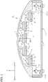
- Fig. 1 is a sectional view of a headlight 1 taken approximately along a line 4-4 in Fig. 2 .
- the headlight 1 shown in the drawing is configured to be disposed at a front part of a motorcycle, which is not shown in the drawing, and to illuminate the front side of the vehicle.
- the headlight 1 includes an outer lens 2 and a housing 3.
- the outer lens 2 is provided at a front side of the headlight 1.
- the housing 3 has an opening that opens toward the front side and that is covered with the outer lens 2.
- the outer lens 2 and the housing 3 form an internal space as a light chamber 4.
- the light chamber 4 contains an extension 6 that is supported via optical axis adjusters 5.
- the extension 6 supports one or multiple (in this example, five) lamp units 7.
- the number and the arrangement of the lamp units 7 are not limited to those shown in the drawing and can be freely set.
- Fig. 1 shows the entirety of the lamp assembly 8 instead of showing a section thereof.
- the integrated body of the lamp assembly 8 and the housing 3 that are integrated via the optical axis adjusters 5 is referred as a "headlight main unit 9".
- the lamp units 7 are arranged in two steps in the front-rear direction. Three of the lamp units 7 are arranged side by side at a position that protrudes most toward the front side. One of the lamp units 7 at each left and right side is arranged rearward of the lamp units 7 at the center, by one step.
- the extension 6 is symmetric in the left-right direction in the condition of being disposed as shown in the drawing.
- the extension 6 is formed in a step shape by changing height in the front-rear direction and has three kinds of steps of an upper step 6a, a middle step 6b, and a lower step 6c.
- the shape of the extension 6 is not limited to that shown in the drawing and is formed into any shape in accordance with design and other factors of the headlight 1.
- the center part in the left-right direction forms the upper step 6a that protrudes most toward the front side.
- the upper step 6a supports three of the lamp units 7.
- the middle steps 6b are lowered by approximately the height of one lamp unit 7.
- the middle steps 6b respectively support one of the lamp units 7.
- the lower step 6c is the lowest step that is formed at each of left and right ends of the extension 6.
- the lower step 6c is coupled to the housing 3 via the optical axis adjuster 5.
- the lamp unit 7 is fixed to the extension 6 and is integrated therewith, thereby tilting integrally with the extension 6 in adjusting the optical axis.
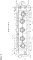
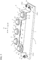
- Figs. 2 to 4 show the lamp assembly 8 in conjunction with the housing 3 and the optical axis adjusters 5.
- Fig. 2 is a front view
- Fig. 3 is a perspective view
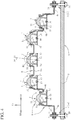
- Fig. 4 is a sectional view taken along the line 4-4 in Fig. 2.
- Fig. 2 shows the outer lens 2 by an imaginary line.
- a tubular step part 10 is formed at a front surface of the extension 6 so as to protrude toward the front side, and a projection lens 11 of the lamp unit 7 is fitted into the step part 10 to cause a front surface to protrude from the step part 10 toward the front side.
- the extension 6 is made of an appropriate material of metal or resin.
- the extension 6 is made of a thermoplastic colored resin and is formed in an approximately rectangular shape long in the left-right direction (vehicle width direction) as viewed from the front ( Fig. 2 ). This shape is merely an example, and the extension 6 is formed in any shape according to various designs of the headlight 1.
- the extension 6 is made opaque as a whole, so as not to transmit light and not to allow the inside to be viewed from the outside therethrough.
- the means of making the extension 6 opaque includes, for example, forming using a colored resin material as the material of the extension 6 and forming an opaque surface layer by coating, plating, or other method.
- the extension 6 is made opaque by using a colored resin material.
- the lamp unit 7 includes the projection lens 11, a lens holder 12, and a substrate 13 that are integrated, and the lamp unit 7 is supported by the extension 6.
- the projection lens 11 is made of a convex lens.
- the lens holder 12 has a tubular shape for holding the projection lens 11.
- the substrate 13 is provided with an electric circuit for lighting a light source, which will be described later.
- the lamp unit 7 is fixed to the extension 6 by each type of methods including tightening using a screw or other fittings, bonding, and laser welding. The laser welding will be described later.
- the extension 6 has a right side 6d, a left side 6e, an upper side 6f, and a lower side 6g as viewed the front.
- a first optical axis adjuster 5a is provided at a lower right corner at which the right side 6d and the lower side 6g join to each other
- a second optical axis adjuster 5b is provided at an upper left corner at which the left side 6e and the upper side 6f join to each other
- a third optical axis adjuster 5c is provided at a lower left corner at which the left side 6e and the lower side 6g join to each other.
- the optical axis is adjusted in the left-right direction and the up-down direction by using these three points.
- the third optical axis adjuster 5c functions as a supporting point.
- Fig. 5 is an enlarged sectional view of the lamp unit 7 taken along a line 5-5 in Fig. 1 .
- the lamp unit 7 includes the projection lens 11 and the tubular lens holder 12.
- the lens holder 12 is formed tapered approximately toward the rear side (lower direction in this drawing).
- the projection lens 11 is mounted at the opening on the front side of the lens holder 12.
- the lens holder 12 is made of an appropriate material of metal or resin.
- the lens holder 12 is formed by using thermoplastic colored resin and is made opaque as a whole.
- the means of making the lens holder 12 opaque includes forming an opaque surface layer by coating, plating, or other method, as in the case of the extension 6, as described above.
- the projection lens 11 is a convex lens and integrally has a lens flange 14 with an outer flange shape that extends radially outward from the circumference of the projection lens 11.
- the lens flange 14 is overlapped on a holder flange 15 with an outer flange shape formed at an end surface on the front side of the lens holder 12, and the projection lens 11 and the lens holder 12 are integrally joined by an appropriate method such as bonding.
- the step part 10 covers the lens flange 14. That is, the step part 10 has a step shape with an approximately L-shaped cross section and has a flat part 10a with an inner flange shape so as to mount on the lens flange 14.
- the flat part 10a is formed with a circular opening that serves as a lens hole 10b, from which the projection lens 11 protrudes toward the front side.
- the lens hole 10b is an example of a lamp hole of the present application.
- the step part 10 has a tubular part 10c that bends from the flat part 10a toward the lower side in the drawing to continue to the extension 6.
- the tubular part 10c protrudes toward the front side integrally from the upper step 6a (or the middle step 6b) of the extension 6 by a predetermined height.
- the lens flange 14 of the projection lens 11 and the flat part 10a of the step part 10 are joined by an appropriate method such as bonding, thereby integrating the lamp unit 7 and the extension 6.
- the circumference of the projection lens 11 and the step part 10 of the extension 6 are brought into close contact with each other without a space.
- the circumference of the projection lens 11 and the step part 10 of the extension 6 do not to have therebetween a conventional space for adjusting the optical axis, which is formed between the circumference of the projection lens and the extension.
- the space for adjusting the optical axis of a conventional headlight is large enough to be viewable and to allow the inside structure of the housing, the optical axis adjuster, and other components, to be viewed therethrough.
- the circumference of the projection lens 11 and the step part 10 of the extension 6 are brought into close contact with each other without a space in the present application. This represents a condition in which the space that is large enough to allow the inside structure to be viewed and to be visually observed is not formed between the circumference of the projection lens 11 and the extension 6.
- the length in the front-rear direction (length in the upper-lower direction in the drawing) of the lens holder 12 is approximately the same as a rear-side focal distance of the projection lens 11.
- the substrate 13 is attached with a screw 18 so as to cover an opening on the rear side of the lens holder 12.
- the rear-side focus is denoted by "F".
- the substrate 13 includes a semiconductor light source 16 that is provided approximately at the rear-side focus F of the projection lens 11.
- the semiconductor light source 16 is made of an LED.
- the semiconductor light source 16 generates light upon being supplied with electric power from the substrate 13 and emits the generated light toward the front side.
- the light that is emitted from the semiconductor light source 16 is refracted at the projection lens 11 into approximately parallel beams and illuminate the front.
- the symbol “17” denotes a coupler that couples the circuit of the substrate 13 to a power source line or other component (not shown).
- Fig. 6 is a sectional view showing the second optical axis adjuster 5b as the optical axis adjuster 5.
- the first optical axis adjuster 5a and the third optical axis adjuster 5c have structures similar to that of the second optical axis adjuster 5b.
- the optical axis adjuster 5 is the same as one that is conventionally used.
- the second optical axis adjuster 5b (optical axis adjuster 5) includes an adjust bolt 20 and an adjust nut 21.
- the adjust bolt 20 is attached the housing 3.
- the adjust nut 21 is attached to the extension 6 to be tightened with the adjust bolt 20.
- the adjust bolt 20 has a shank 20a and a head 20b that are passed through a bolt passing hole 3a of the housing 3 from the lower side in the drawing.
- the head 20b and a rear surface (lower surface in the drawing) of the housing 3 have an elastic body 22 that is interposed therebetween as a seal.
- the elastic body 22 is formed of a rubber O-ring or other material.
- the shank 20a is retained in the housing 3 by a clip 23.
- the clip 23 is formed of a publicly known material such as a C-ring or an E-ring.
- the adjust nut 21 is tightened in the vicinity of a large-diameter hole 6h that is provided at an end of the extension 6, to the screw part 26 of the adjust bolt 20 that passes through the large-diameter hole 6h.
- the adjust nut 21 has a holding part 24 that holds upper and lower sides of the extension 6 around the large-diameter hole 6h.
- the holding part 24 is formed with a tapered surface 25 in which a radially outward side is gradually separated from the surface of the extension 6.
- the screw part 26 of the adjust bolt 20 penetrates through the centers of the large-diameter hole 6h and the adjust nut 21. Rotating the adjust bolt 20 makes the adjust nut 21 advance or retreat on the adjust bolt 20 to change the tilt of the extension 6.
- the first optical axis adjuster 5a and the third optical axis adjuster 5c being a supporting point are on an up-down adjusting axis line L1
- the second optical axis adjuster 5b and the third optical axis adjuster 5c are on a left-right adjusting axis line L2.
- the adjust bolt 20 at the first optical axis adjuster 5a when the adjust bolt 20 at the first optical axis adjuster 5a is rotated, the adjust nut 21 advances or retreats, and as shown by an imaginary line in Fig. 4 , the lamp assembly 8 makes the extension 6 turn and tilt around the left-right adjusting axis line L2 centering on the supporting point at the third optical axis adjuster 5c.
- Fig. 7 is a sectional view taken along a line 7-7 in Fig. 2 .
- each of the second optical axis adjuster 5b and the third optical axis adjuster 5c is shown in the drawing in a simplified manner.
- the adjust nut 21 when the adjust nut 21 is moved toward the front side, the extension 6 tilts downwardly with the supporting point at the third optical axis adjuster 5c, and the optical axis is adjusted from the original optical axis J0 to an optical axis J2 that faces downward. Reversely rotating the adjust bolt 20 makes the optical axis being adjusted in the reverse direction.
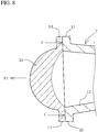
- Fig. 8 shows a method of joining using laser welding.
- the lens flange 14 of the projection lens 11 is overlapped on the holder flange 15 of the lens holder 12 from the front side, and laser light C is emitted to the lens flange 14 from the front side.
- the emitted laser light C transmits the lens flange 14 because the lens flange 14 is transparent. However, the laser light C does not transmit the holder flange 15 of the lens holder 12 because the holder flange 15 is made of an opaque thermoplastic colored resin, and the laser light C illuminates and melts an end surface of the holder flange 15 of the lens holder 12.
- the laser light C is emitted from the front side while using the transparent projection lens 11, whereby the lens flange 14 is easily and rapidly welded to an end surface of the lens holder 12 and is efficiently integrated therewith.
- the welded positions are provided at equal intervals or at unequal intervals in the circumferential direction. It is sufficient to provide a relatively small number of the welded positions, such as three or four welded positions.
- the holder flange 15 may be provided as protrusions 15b that are intermittently formed in the circumferential direction by cut parts 15a.
- the number of the protrusions 15b is made to agree with the number of the welded positions.
- four protrusions 15b may be provided at equal intervals in the circumferential direction, and the lens flange 14 may be overlapped and laser welded to these protrusions 15b.
- the protrusions 15b and the entire circumferential holder flange 15 are not necessary, and the lens flange 14 can be directly welded to the end surface of the lens holder 12. Laser welding enables welding a relatively small area as in the end surface of the opening of the lens holder 12.
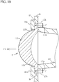
- Fig. 10 shows an example of welding the extension 6 to the front side of the lens flange 14 of the projection lens 11.
- the projection lens 11 is fitted into the lens hole 10b of the step part 10, which is formed to the extension 6, and the flat part 10a is overlapped on the front side of the lens flange 14.
- the flat part 10a corresponds to an overlapping portion of the present application.
- the flat part 10a is overlapped on the lens flange 14.
- the extension 6 is formed of thermoplastic resin that is colored so as to be opaque for not transmitting light and that melts by heat.
- the holder flange 15 of the lens holder 12 has the cut parts 15a that are provided in accordance with the positions to be laser welded, and the cut parts 15a and the protrusions 15b are alternately formed in the circumferential direction.
- the laser light C when the laser light C is emitted into the cut part 15a from the rear side, the laser light C transmits the cut part 15a, further transmits the transparent lens flange 14, and illuminates and melts the flat part 10a of the extension 6, which is the colored opaque thermoplastic resin.
- the extension 6 and the projection lens 11 are integrally welded via the lens flange 14.
- the substrate 13 may prevent the laser light from illuminating the part of the lens flange 14 in some cases (refer to Fig. 5 ).
- the projection lens 11 that is integrated with the lens holder 12, and the extension 6, are welded prior to attaching the substrate 13 to the lens holder 12.
- the lens flange 14 may be made larger than the substrate 13 to overhang more than the substrate 13 or the substrate 13 may be provided with a hole or a cut part through which the lens flange 14 is viewable from the rear side.
- the laser welding can be performed in the condition in which the substrate 13 is preliminarily attached to the lens holder 12.
- Fig. 11 shows an example of welding the extension 6 to a rear side of the lens flange 14, in contrary to the example shown in Fig. 10 .
- a holder hole 30 for fitting the holder flange 15 of the lens holder 12 is provided to the extension 6 (refer to Fig. 12 ).
- the holder hole 30 is an example of a lamp hole of the present application.
- Fig. 12 shows the holder hole 30 and the surrounding extension 6.
- the holder hole 30 receives the holder flange 15 that protrudes radially outward by a relatively small amount.
- the circumference of the holder hole 30 is formed into an overlapping portion 31 on which the lens flange 14 is overlapped from the front side.
- the lens holder 12 is fitted into the holder hole 30 from a small-diameter side (rear side), and the lens flange 14 of the projection lens 11, which is preliminarily mouthed to the holder flange 15 by bonding or other means, is overlapped on the overlapping portion 31 from the front side.
- the laser light C is emitted from the front side to the lens flange 14.
- the emitted laser light C transmits the lens flange 14 and illuminates and melts the opaque overlapping portion 31, thereby welding the overlapping portion 31 on the rear side of the lens flange 14.
- the lens flange 14 of the projection lens 11 is overlapped on the holder flange 15 of the lens holder 12 and is joined thereto by bonding or other means.
- a space that is large enough to allow the inside structure to be viewed and to be visually observable is not formed between the projection lens 11 and the extension 6.
- the lamp unit 7 is fixed on the extension 6 and is integrated therewith. This enables the optical axis adjusters 5 to change the tilt of the extension 6, thereby adjusting the optical axis.
- the lamp unit 7 and the extension 6 keep no space therebetween, whereby a good appearance is maintained.
- optical axis adjuster 5 has the same structure as that of a conventional one, and therefore, a conventional component can be used without changing, thereby improving versatility.
- the circumference of the projection lens 11 is provided with the ring-shaped step part 10 that covers the lens flange 14 at a rim part of the projection lens 11.
- the step part 10 prevents the light from leaking from the circumference of the projection lens 11, thereby improving quality of the headlight 1.
- step part 10 is easily formed as a part of the extension 6, and the step part 10 can also be used as a fixing part for the projection lens 11.
- the laser light C is emitted through the transparent lens flange 14 of the projection lens 11 to the overlapping portion 31 (10a) of the extension 6, which is made of the opaque thermoplastic resin, or to the holder flange 15 of the lens holder 12.
- the overlapping portion 31 (10a) or the holder flange 15 is melted and is welded to the lens flange 14.
- the projection lens 11 and the extension 6 or the lens holder 12 are efficiently joined together by laser welding.
- the laser welding is suitable for manufacturing the headlight 1 having the lamp unit 7 that is fixed to the extension 6.
- Fig. 13 relates to a second example in which the optical axis of the lamp unit 7 is directly adjusted.
- Fig. 13 is a sectional view of a part similar to that shown in Fig. 7 .
- the parts that are common between the forgoing example and this example are denoted by common symbols.
- one or multiple lamp units 7 are mounted on a bracket 40 (the drawing shows only one lamp unit 7 as an example).
- the bracket 40 is coupled to the housing 3 by the optical axis adjusters 5 so as to enable optical axis adjustment.
- the optical axis adjusters 5 are similar to those used in the first example.
- Each of the optical axis adjusters 5 is shown in a simplified manner.
- the bracket 40 having dimensions and a shape that enable attaching these optical axis adjusters is provided.
- the lamp unit 7 is fixed to the extension 6 and is integrated therewith, thereby constituting the lamp assembly 8.
- the lamp unit 7 is joined so as to have an integrated structure similar to that in the forgoing example.
- a large space corresponding to a conventional space for adjusting the optical axis is not formed between the extension 6 and the lamp unit 7, and more exactly, between the projection lens 11 protruding from the extension 6 and the surrounding extension 6.
- the extension 6 is different from that in the forgoing example.
- the extension 6 is not directly coupled to the housing 3, but is indirectly supported by the housing 3 via the lamp unit 7 in a condition of being separated from the housing 3.
- the bracket 40 tilts while the lamp assembly 8 tilts integrally with the bracket 40.
- the lamp unit 7 also tilts together with the bracket 40, whereby the optical axis is adjusted.
- the extension 6 also tilts in an integral manner.
- the optical axis can be adjusted also by this method.
- the extension 6 and the lamp unit 7 have no space therebetween, thereby preventing the optical axis adjusters 5 and other components in the housing 3 from being viewed from the outside through the outer lens 2. Thus, a good appearance is obtained and is maintained.
- the fixing structure of the lamp unit 7 to the extension 6 is freely selected, and instead of the projection lens 11, the lens holder 12 may be fixed to the extension 6 by any appropriate method.
- the projection lens 11 is fixed to the extension 6, the inside structure is hidden by the extension 6 by the maximum amount.
- the step part 10, the lens flange 14, and the holder flange 15, and other components are not essential, and it is possible to omit any one or all of these components. Even in the case of omitting the lens flange 14, the extension 6 and the lens holder 12 can be laser welded, as described above, by making laser light transmit a circumferential part of the transparent projection lens 11.
- the light source of the lamp unit 7 can also use any publicly known components other than the semiconductor light source 16.
- the headlight 1 can also be used in each type of vehicles other than the motorcycle.
- the present invention relates to a supporting structure of a lamp unit in a headlight and enables making the headlight have a good appearance, and therefore, the present invention is useful in the field of vehicle headlight.
- 1 headlight
- 2 outer lens
- 3 housing
- 4 light chamber
- 5 optical axis adjuster
- 6 extension
- 7 lamp unit
- 8 lamp assembly
- 10 step part
- 11 projection lens
- 12 lens holder
- 13 substrate
- 14 lens flange
- 15 holder flange
- 16 semiconductor light source
- 20 adjust bolt
- 21 adjust nut
Abstract
Description
- The present invention relates to a lamp unit supporting structure for a headlight having no space between a lamp unit and an extension and also relates to a manufacturing method suitable for the headlight.
- A headlight for a vehicle, such as a motorcycle, may include a housing that opens toward front side and an outer lens that covers the opening (refer to Patent Literature 1). The housing and the outer lens form a light chamber that houses a lamp unit having a projection lens and a light source. The lamp unit and the housing have an extension disposed therebetween. The whole of the lamp unit is made movable to adjust an optical axis. The extension is provided to make an optical axis adjuster and other components in the housing hardly visible when the inside of the headlight is looked from the outside through the outer lens, thereby improving the appearance.
- Patent Literature 1: Japanese Unexamined Patent Application Laid-Open No.
2008-76088 - The headlight as described above has the extension that is fixed in a manner unmovable to the housing side. Thus, in a case in which the lamp unit is made movable in order to adjust the optical axis, a space for the movement of the lamp unit must be secured. Inevitably, a certain space for adjusting the optical axis is provided between the lamp unit and the surrounding extension.
- This space for adjusting the optical axis may allow the optical axis adjuster and other components inside the headlight to be partially viewed from the outside and may lessen the original effects of the extension although the extension is provided to improve the appearance. In view of this, it is desirable to eliminate such a space for adjusting the optical axis.
- However, the space for adjusting the optical axis is essential in the case of adjusting the optical axis by making the whole of the lamp unit movable, and it is indispensable.
- In view of these circumstances, an object of the present application is to enable adjusting the optical axis while dispensing with such a space for adjusting the optical axis.
- To achieve the above object, according to an aspect of the invention of the present application, a lamp unit (7) is fitted into a lamp hole and is fixed to an extension (6), and the lamp unit (7) and the extension (6) are configured to tilt integrally in adjusting an optical axis by an optical axis adjuster (5). This enables adjusting optical axis without providing a space for adjusting the optical axis between the lamp unit (7) and the extension (6).
- At this time, the optical axis adjuster (5) may be provided between the extension (6) and a housing (3), and the optical axis may be adjusted by tilting the extension (6).
- On the other hand, the optical axis adjuster (5) may be provided between the lamp unit (7) and the housing (3), and the extension (6) may be supported by the housing (3) via the lamp unit (7). In this case, the optical axis may be adjusted by tilting the lamp unit (7) by the optical axis adjuster (5).
- In each of these cases, the extension (6) tilts integrally with the lamp unit (7) in adjusting the optical axis, whereby the extension (6) and the lamp unit (7) keep no space for adjusting the optical axis, therebetween.
- A manufacturing method of the headlight includes
fitting the lamp unit (7) into a lamp hole that is provided to the extension (6) made of a thermoplastic resin, and the lamp unit (7) having a light source and a projection lens (11) that is configured to collect light from the light source,
overlapping a circumferential edge part of the projection lens (11) on an opaque overlapping portion (31) that is a part surrounding the lamp hole of the extension (6), emitting laser light to the overlapping portion (31) through the circumferential edge part of the projection lens (11), and
performing laser welding of the overlapping portion (31) to the circumferential edge part of the projection lens (11) by melting the overlapping portion (31). - The extension (6) is fixed to the lamp unit (7) to enable tilting the extension (6) and the lamp unit (7) integrally in adjusting the optical axis. This eliminates the need to provide a space for adjusting the optical axis between the extension (6) and the lamp unit (7), which is conventionally required for adjusting the optical axis. Thus, the optical axis is adjustable although a space for adjusting the optical axis is not provided, and the inside structure is not viewable from between the lamp unit and the extension, whereby an appearance of the headlight is improved.
- In the case of providing the optical axis adjuster (5) between the extension (6) and the housing (3), the optical axis is adjusted by tilting the extension (6) to cause the extension (6) and the lamp unit (7) to tilt at the same time, by the optical axis adjuster (5). Moreover, in the case in which the extension (6) is supported by the housing (3) via the lamp unit (7), and the optical axis adjuster (5) is provided between the lamp unit (7) and the housing (3), the optical axis is adjusted by tilting the lamp unit (7) to cause the lamp unit (7) and the extension (6) to tilt at the same time, by the optical axis adjuster (5).
- In the manufacturing method of the headlight of the invention of the present application, the lamp unit (7) is fitted into the lamp hole provided to the extension (6), and the circumferential edge part of the projection lens (11) is overlapped on the overlapping portion (31) that is the part surrounding the lamp hole of the extension (6).
- Moreover, laser light is emitted to the overlapping portion (31) through the circumferential edge part of the projection lens (11). The emitted laser light transmits the circumferential edge part of the opaque projection lens (11) and melts the overlapping portion (31). Thus, the circumferential edge part of the projection lens (11) and the extension (6) are joined by laser welding. This enables efficient laser welding using the transparent projection lens (11). That is, the manufacturing method is suitable in manufacturing a headlight having the lamp unit (7) that is fixed to the extension (6).
-
-
Fig. 1 is a sectional view of a headlight according to a first example. -
Fig. 2 is a front view of a main unit of the headlight according to the first example. -
Fig. 3 is a perspective view of the main unit of the headlight. -
Fig. 4 is a sectional view of the main unit of the headlight taken along a line 4-4 inFig. 2 . -
Fig. 5 is an enlarged sectional view of a lamp unit taken along a line 5-5 inFig. 1 . -
Fig. 6 is a sectional view of an optical axis adjuster. -
Fig. 7 is a sectional view of the main unit of the headlight taken along a line 7-7 inFig. 2 . -
Fig. 8 is a sectional view showing a process of laser welding a projection lens and a lens holder. -
Fig. 9 shows a modification example of a holder flange. -
Fig. 10 is a sectional view showing a process of laser welding the projection lens to a rear side of an extension. -
Fig. 11 is a sectional view showing a process of laser welding the projection lens to a front side of the extension. -
Fig. 12 shows a part of a lamp hole of the extension. -
Fig. 13 is a sectional view of a part approximately corresponding to that shown inFig. 7 , according to a second example. - Hereinafter, an embodiment relating to a headlight for a motorcycle will be described with reference to the drawings.
- Note that a front-rear direction, a left-right direction, and an up-down direction represent directions relative to a vehicle, and as necessary, a front direction, a left direction, and a right direction are indicated by arrows Fr, LH, and RH, respectively. A front direction of a headlight, a lamp unit, and a projection lens is an emitting direction of light.
- First, a first example will be described with reference to
Figs. 1 to 12 .Fig. 1 is a sectional view of aheadlight 1 taken approximately along a line 4-4 inFig. 2 . Theheadlight 1 shown in the drawing is configured to be disposed at a front part of a motorcycle, which is not shown in the drawing, and to illuminate the front side of the vehicle. Theheadlight 1 includes anouter lens 2 and ahousing 3. Theouter lens 2 is provided at a front side of theheadlight 1. Thehousing 3 has an opening that opens toward the front side and that is covered with theouter lens 2. Theouter lens 2 and thehousing 3 form an internal space as alight chamber 4. - The
light chamber 4 contains anextension 6 that is supported viaoptical axis adjusters 5. Theextension 6 supports one or multiple (in this example, five)lamp units 7. The number and the arrangement of thelamp units 7 are not limited to those shown in the drawing and can be freely set. - The integrated body of the
lamp units 7 and theextension 6 is referred as a "lamp assembly 8".Fig. 1 shows the entirety of thelamp assembly 8 instead of showing a section thereof. - In addition, the integrated body of the
lamp assembly 8 and thehousing 3 that are integrated via theoptical axis adjusters 5 is referred as a "headlightmain unit 9". - The
lamp units 7 are arranged in two steps in the front-rear direction. Three of thelamp units 7 are arranged side by side at a position that protrudes most toward the front side. One of thelamp units 7 at each left and right side is arranged rearward of thelamp units 7 at the center, by one step. - The
extension 6 is symmetric in the left-right direction in the condition of being disposed as shown in the drawing. Theextension 6 is formed in a step shape by changing height in the front-rear direction and has three kinds of steps of anupper step 6a, amiddle step 6b, and alower step 6c. - The shape of the
extension 6 is not limited to that shown in the drawing and is formed into any shape in accordance with design and other factors of theheadlight 1. - The center part in the left-right direction forms the
upper step 6a that protrudes most toward the front side. Theupper step 6a supports three of thelamp units 7. - The
middle steps 6b are lowered by approximately the height of onelamp unit 7. Themiddle steps 6b respectively support one of thelamp units 7. - The
lower step 6c is the lowest step that is formed at each of left and right ends of theextension 6. Thelower step 6c is coupled to thehousing 3 via theoptical axis adjuster 5. - The
lamp unit 7 is fixed to theextension 6 and is integrated therewith, thereby tilting integrally with theextension 6 in adjusting the optical axis. -
Figs. 2 to 4 show thelamp assembly 8 in conjunction with thehousing 3 and theoptical axis adjusters 5.Fig. 2 is a front view,Fig. 3 is a perspective view, andFig. 4 is a sectional view taken along the line 4-4 inFig. 2. Fig. 2 shows theouter lens 2 by an imaginary line. - As shown in these drawings, a
tubular step part 10 is formed at a front surface of theextension 6 so as to protrude toward the front side, and aprojection lens 11 of thelamp unit 7 is fitted into thestep part 10 to cause a front surface to protrude from thestep part 10 toward the front side. - The
extension 6 is made of an appropriate material of metal or resin. In this example, theextension 6 is made of a thermoplastic colored resin and is formed in an approximately rectangular shape long in the left-right direction (vehicle width direction) as viewed from the front (Fig. 2 ). This shape is merely an example, and theextension 6 is formed in any shape according to various designs of theheadlight 1. - The
extension 6 is made opaque as a whole, so as not to transmit light and not to allow the inside to be viewed from the outside therethrough. The means of making theextension 6 opaque includes, for example, forming using a colored resin material as the material of theextension 6 and forming an opaque surface layer by coating, plating, or other method. In this example, theextension 6 is made opaque by using a colored resin material. - The
lamp unit 7 includes theprojection lens 11, alens holder 12, and asubstrate 13 that are integrated, and thelamp unit 7 is supported by theextension 6. Theprojection lens 11 is made of a convex lens. Thelens holder 12 has a tubular shape for holding theprojection lens 11. Thesubstrate 13 is provided with an electric circuit for lighting a light source, which will be described later. Thelamp unit 7 is fixed to theextension 6 by each type of methods including tightening using a screw or other fittings, bonding, and laser welding. The laser welding will be described later. - As shown in
Fig. 2 , theextension 6 has aright side 6d, aleft side 6e, anupper side 6f, and alower side 6g as viewed the front. - In this example, a first
optical axis adjuster 5a is provided at a lower right corner at which theright side 6d and thelower side 6g join to each other, a secondoptical axis adjuster 5b is provided at an upper left corner at which theleft side 6e and theupper side 6f join to each other, and a thirdoptical axis adjuster 5c is provided at a lower left corner at which theleft side 6e and thelower side 6g join to each other. The optical axis is adjusted in the left-right direction and the up-down direction by using these three points. In this example, the thirdoptical axis adjuster 5c functions as a supporting point. -
Fig. 5 is an enlarged sectional view of thelamp unit 7 taken along a line 5-5 inFig. 1 . Thelamp unit 7 includes theprojection lens 11 and thetubular lens holder 12. Thelens holder 12 is formed tapered approximately toward the rear side (lower direction in this drawing). Theprojection lens 11 is mounted at the opening on the front side of thelens holder 12. Thelens holder 12 is made of an appropriate material of metal or resin. In this example, thelens holder 12 is formed by using thermoplastic colored resin and is made opaque as a whole. The means of making thelens holder 12 opaque includes forming an opaque surface layer by coating, plating, or other method, as in the case of theextension 6, as described above. - The
projection lens 11 is a convex lens and integrally has alens flange 14 with an outer flange shape that extends radially outward from the circumference of theprojection lens 11. Thelens flange 14 is overlapped on aholder flange 15 with an outer flange shape formed at an end surface on the front side of thelens holder 12, and theprojection lens 11 and thelens holder 12 are integrally joined by an appropriate method such as bonding. - Apart of the
step part 10 covers thelens flange 14. That is, thestep part 10 has a step shape with an approximately L-shaped cross section and has aflat part 10a with an inner flange shape so as to mount on thelens flange 14. - The
flat part 10a is formed with a circular opening that serves as alens hole 10b, from which theprojection lens 11 protrudes toward the front side. Thelens hole 10b is an example of a lamp hole of the present application. - The
step part 10 has atubular part 10c that bends from theflat part 10a toward the lower side in the drawing to continue to theextension 6. Thetubular part 10c protrudes toward the front side integrally from theupper step 6a (or themiddle step 6b) of theextension 6 by a predetermined height. - The
lens flange 14 of theprojection lens 11 and theflat part 10a of thestep part 10 are joined by an appropriate method such as bonding, thereby integrating thelamp unit 7 and theextension 6. - The circumference of the
projection lens 11 and thestep part 10 of theextension 6 are brought into close contact with each other without a space. The circumference of theprojection lens 11 and thestep part 10 of theextension 6 do not to have therebetween a conventional space for adjusting the optical axis, which is formed between the circumference of the projection lens and the extension. - The space for adjusting the optical axis of a conventional headlight is large enough to be viewable and to allow the inside structure of the housing, the optical axis adjuster, and other components, to be viewed therethrough. On the other hand, the circumference of the
projection lens 11 and thestep part 10 of theextension 6 are brought into close contact with each other without a space in the present application. This represents a condition in which the space that is large enough to allow the inside structure to be viewed and to be visually observed is not formed between the circumference of theprojection lens 11 and theextension 6. - The length in the front-rear direction (length in the upper-lower direction in the drawing) of the
lens holder 12 is approximately the same as a rear-side focal distance of theprojection lens 11. Thesubstrate 13 is attached with ascrew 18 so as to cover an opening on the rear side of thelens holder 12. The rear-side focus is denoted by "F". - The
substrate 13 includes asemiconductor light source 16 that is provided approximately at the rear-side focus F of theprojection lens 11. Thesemiconductor light source 16 is made of an LED. - The
semiconductor light source 16 generates light upon being supplied with electric power from thesubstrate 13 and emits the generated light toward the front side. The light that is emitted from thesemiconductor light source 16 is refracted at theprojection lens 11 into approximately parallel beams and illuminate the front. The symbol "17" denotes a coupler that couples the circuit of thesubstrate 13 to a power source line or other component (not shown). -
Fig. 6 is a sectional view showing the secondoptical axis adjuster 5b as theoptical axis adjuster 5. The firstoptical axis adjuster 5a and the thirdoptical axis adjuster 5c have structures similar to that of the secondoptical axis adjuster 5b. Theoptical axis adjuster 5 is the same as one that is conventionally used. - The second
optical axis adjuster 5b (optical axis adjuster 5) includes an adjustbolt 20 and an adjustnut 21. The adjustbolt 20 is attached thehousing 3. The adjustnut 21 is attached to theextension 6 to be tightened with the adjustbolt 20. - The adjust
bolt 20 has ashank 20a and ahead 20b that are passed through a bolt passing hole 3a of thehousing 3 from the lower side in the drawing. Thehead 20b and a rear surface (lower surface in the drawing) of thehousing 3 have anelastic body 22 that is interposed therebetween as a seal. Theelastic body 22 is formed of a rubber O-ring or other material. Theshank 20a is retained in thehousing 3 by aclip 23. Theclip 23 is formed of a publicly known material such as a C-ring or an E-ring. - The adjust
nut 21 is tightened in the vicinity of a large-diameter hole 6h that is provided at an end of theextension 6, to thescrew part 26 of the adjustbolt 20 that passes through the large-diameter hole 6h. The adjustnut 21 has a holdingpart 24 that holds upper and lower sides of theextension 6 around the large-diameter hole 6h. The holdingpart 24 is formed with atapered surface 25 in which a radially outward side is gradually separated from the surface of theextension 6. - The
screw part 26 of the adjustbolt 20 penetrates through the centers of the large-diameter hole 6h and the adjustnut 21. Rotating the adjustbolt 20 makes the adjustnut 21 advance or retreat on the adjustbolt 20 to change the tilt of theextension 6. - As shown in
Fig. 2 , the firstoptical axis adjuster 5a and the thirdoptical axis adjuster 5c being a supporting point are on an up-down adjusting axis line L1, and the secondoptical axis adjuster 5b and the thirdoptical axis adjuster 5c are on a left-right adjusting axis line L2. - In these conditions, when the adjust
bolt 20 at the firstoptical axis adjuster 5a is rotated, the adjustnut 21 advances or retreats, and as shown by an imaginary line inFig. 4 , thelamp assembly 8 makes theextension 6 turn and tilt around the left-right adjusting axis line L2 centering on the supporting point at the thirdoptical axis adjuster 5c. - Assuming that the adjust
nut 21 at the firstoptical axis adjuster 5a is moved to the upper side inFig. 4 , as shown by the imaginary line, theextension 6 tilts to the left side, thereby making an original optical axis J0 move to a position of an optical axis J1, whereby the optical axis is adjusted in the left-right direction. Reversely rotating the adjustbolt 20 makes the optical axis being adjusted in the reverse direction. - In the condition as shown in
Fig. 2 , when the adjustbolt 20 of the secondoptical axis adjuster 5b is rotated, theextension 6 tilts around the up-down adjusting axis line L1. This optical axis adjustment in the up-down direction is shown inFig. 7. Fig. 7 is a sectional view taken along a line 7-7 inFig. 2 . In this case, each of the secondoptical axis adjuster 5b and the thirdoptical axis adjuster 5c is shown in the drawing in a simplified manner. - As shown in
Fig. 7 , for example, when the adjustnut 21 is moved toward the front side, theextension 6 tilts downwardly with the supporting point at the thirdoptical axis adjuster 5c, and the optical axis is adjusted from the original optical axis J0 to an optical axis J2 that faces downward. Reversely rotating the adjustbolt 20 makes the optical axis being adjusted in the reverse direction. - Next, a method of joining the
projection lens 11 and thelens holder 12 will be described. Although this joining is performed by any appropriate method such as bonding, it is performed efficiently by laser welding. -
Fig. 8 shows a method of joining using laser welding. First, thelens flange 14 of theprojection lens 11 is overlapped on theholder flange 15 of thelens holder 12 from the front side, and laser light C is emitted to thelens flange 14 from the front side. - The emitted laser light C transmits the
lens flange 14 because thelens flange 14 is transparent. However, the laser light C does not transmit theholder flange 15 of thelens holder 12 because theholder flange 15 is made of an opaque thermoplastic colored resin, and the laser light C illuminates and melts an end surface of theholder flange 15 of thelens holder 12. - Thus, the laser light C is emitted from the front side while using the
transparent projection lens 11, whereby thelens flange 14 is easily and rapidly welded to an end surface of thelens holder 12 and is efficiently integrated therewith. - The welded positions are provided at equal intervals or at unequal intervals in the circumferential direction. It is sufficient to provide a relatively small number of the welded positions, such as three or four welded positions.
- In this case, instead of forming the
holder flange 15 with a ring shape continuous over the entire circumference, as shown inFig. 9 , theholder flange 15 may be provided asprotrusions 15b that are intermittently formed in the circumferential direction bycut parts 15a. The number of theprotrusions 15b is made to agree with the number of the welded positions. For example, fourprotrusions 15b may be provided at equal intervals in the circumferential direction, and thelens flange 14 may be overlapped and laser welded to theseprotrusions 15b. - In a case in which an end surface of the opening of the
lens holder 12 is formed with a sufficiently large width, theprotrusions 15b and the entirecircumferential holder flange 15 are not necessary, and thelens flange 14 can be directly welded to the end surface of thelens holder 12. Laser welding enables welding a relatively small area as in the end surface of the opening of thelens holder 12. - It is also possible to adopt the laser welding to join the
projection lens 11 and theextension 6. The following describes joining of theprojection lens 11 and theextension 6 by laser welding. -
Fig. 10 shows an example of welding theextension 6 to the front side of thelens flange 14 of theprojection lens 11. As shown in the drawing, theprojection lens 11 is fitted into thelens hole 10b of thestep part 10, which is formed to theextension 6, and theflat part 10a is overlapped on the front side of thelens flange 14. Theflat part 10a corresponds to an overlapping portion of the present application. Theflat part 10a is overlapped on thelens flange 14. - In this case, the
extension 6 is formed of thermoplastic resin that is colored so as to be opaque for not transmitting light and that melts by heat. - As shown in
Fig. 9 , theholder flange 15 of thelens holder 12 has thecut parts 15a that are provided in accordance with the positions to be laser welded, and thecut parts 15a and theprotrusions 15b are alternately formed in the circumferential direction. - In these conditions, when the laser light C is emitted into the
cut part 15a from the rear side, the laser light C transmits thecut part 15a, further transmits thetransparent lens flange 14, and illuminates and melts theflat part 10a of theextension 6, which is the colored opaque thermoplastic resin. Thus, theextension 6 and theprojection lens 11 are integrally welded via thelens flange 14. - In the case of thus performing laser welding from the rear side, if the
substrate 13 is attached to thelens holder 12 in advance, thesubstrate 13 may prevent the laser light from illuminating the part of thelens flange 14 in some cases (refer toFig. 5 ). For such cases, theprojection lens 11 that is integrated with thelens holder 12, and theextension 6, are welded prior to attaching thesubstrate 13 to thelens holder 12. - On the other hand, the
lens flange 14 may be made larger than thesubstrate 13 to overhang more than thesubstrate 13 or thesubstrate 13 may be provided with a hole or a cut part through which thelens flange 14 is viewable from the rear side. In this case, the laser welding can be performed in the condition in which thesubstrate 13 is preliminarily attached to thelens holder 12. -
Fig. 11 shows an example of welding theextension 6 to a rear side of thelens flange 14, in contrary to the example shown inFig. 10 . In this example, aholder hole 30 for fitting theholder flange 15 of thelens holder 12 is provided to the extension 6 (refer toFig. 12 ). Theholder hole 30 is an example of a lamp hole of the present application. -
Fig. 12 shows theholder hole 30 and thesurrounding extension 6. Theholder hole 30 receives theholder flange 15 that protrudes radially outward by a relatively small amount. - The circumference of the
holder hole 30 is formed into an overlappingportion 31 on which thelens flange 14 is overlapped from the front side. - As shown in
Fig. 11 , thelens holder 12 is fitted into theholder hole 30 from a small-diameter side (rear side), and thelens flange 14 of theprojection lens 11, which is preliminarily mouthed to theholder flange 15 by bonding or other means, is overlapped on the overlappingportion 31 from the front side. In these conditions, the laser light C is emitted from the front side to thelens flange 14. The emitted laser light C transmits thelens flange 14 and illuminates and melts the opaque overlappingportion 31, thereby welding the overlappingportion 31 on the rear side of thelens flange 14. - Next, the effects of this example will be described. As shown in
Fig. 5 , thelens flange 14 of theprojection lens 11 is overlapped on theholder flange 15 of thelens holder 12 and is joined thereto by bonding or other means. As a result, a space that is large enough to allow the inside structure to be viewed and to be visually observable is not formed between theprojection lens 11 and theextension 6. Thus, it is possible to eliminate a conventional space for adjusting the optical axis, and the inside structure is not viewable from between theextension 6 and thelamp unit 7, whereby a good appearance is obtained. - The
lamp unit 7 is fixed on theextension 6 and is integrated therewith. This enables theoptical axis adjusters 5 to change the tilt of theextension 6, thereby adjusting the optical axis. - During the optical adjustment, the
lamp unit 7 and theextension 6 keep no space therebetween, whereby a good appearance is maintained. - In addition, the
optical axis adjuster 5 has the same structure as that of a conventional one, and therefore, a conventional component can be used without changing, thereby improving versatility. - The circumference of the
projection lens 11 is provided with the ring-shapedstep part 10 that covers thelens flange 14 at a rim part of theprojection lens 11. Thus, while light that is emitted from thesemiconductor light source 16 toward the front side transmits theprojection lens 11, thestep part 10 prevents the light from leaking from the circumference of theprojection lens 11, thereby improving quality of theheadlight 1. - In addition, the
step part 10 is easily formed as a part of theextension 6, and thestep part 10 can also be used as a fixing part for theprojection lens 11. - As shown in
Figs. 8 ,10 , and11 , the laser light C is emitted through thetransparent lens flange 14 of theprojection lens 11 to the overlapping portion 31 (10a) of theextension 6, which is made of the opaque thermoplastic resin, or to theholder flange 15 of thelens holder 12. Thus, the overlapping portion 31 (10a) or theholder flange 15 is melted and is welded to thelens flange 14. Theprojection lens 11 and theextension 6 or thelens holder 12 are efficiently joined together by laser welding. - As a result, it is possible to rapidly and easily join the
lamp unit 7 and theextension 6 and join theprojection lens 11 and thelens holder 12 by laser welding while using thetransparent lens flange 14. - Thus, the laser welding is suitable for manufacturing the
headlight 1 having thelamp unit 7 that is fixed to theextension 6. - Next, another example will be described.
Fig. 13 relates to a second example in which the optical axis of thelamp unit 7 is directly adjusted.Fig. 13 is a sectional view of a part similar to that shown inFig. 7 . The parts that are common between the forgoing example and this example are denoted by common symbols. In this example, one ormultiple lamp units 7 are mounted on a bracket 40 (the drawing shows only onelamp unit 7 as an example). Thebracket 40 is coupled to thehousing 3 by theoptical axis adjusters 5 so as to enable optical axis adjustment. Theoptical axis adjusters 5 are similar to those used in the first example. Each of theoptical axis adjusters 5 is shown in a simplified manner. - In the case of providing three
optical axis adjusters 5 of the firstoptical axis adjuster 5a, the secondoptical axis adjuster 5b, and the thirdoptical axis adjuster 5c, as inFig. 2 , thebracket 40 having dimensions and a shape that enable attaching these optical axis adjusters is provided. - The
lamp unit 7 is fixed to theextension 6 and is integrated therewith, thereby constituting thelamp assembly 8. Thelamp unit 7 is joined so as to have an integrated structure similar to that in the forgoing example. Thus, a large space corresponding to a conventional space for adjusting the optical axis is not formed between theextension 6 and thelamp unit 7, and more exactly, between theprojection lens 11 protruding from theextension 6 and thesurrounding extension 6. - The
extension 6 is different from that in the forgoing example. Theextension 6 is not directly coupled to thehousing 3, but is indirectly supported by thehousing 3 via thelamp unit 7 in a condition of being separated from thehousing 3. - In these conditions, when the optical axis is adjusted by the
optical axis adjusters 5, as shown by imaginary lines, thebracket 40 tilts while thelamp assembly 8 tilts integrally with thebracket 40. As a result, thelamp unit 7 also tilts together with thebracket 40, whereby the optical axis is adjusted. At this time, theextension 6 also tilts in an integral manner. - The optical axis can be adjusted also by this method. The
extension 6 and thelamp unit 7 have no space therebetween, thereby preventing theoptical axis adjusters 5 and other components in thehousing 3 from being viewed from the outside through theouter lens 2. Thus, a good appearance is obtained and is maintained. - The invention of the present application is not limited to the forgoing examples, and various modifications and alterations are possible within the gist of the invention.
- For example, the fixing structure of the
lamp unit 7 to theextension 6 is freely selected, and instead of theprojection lens 11, thelens holder 12 may be fixed to theextension 6 by any appropriate method. - If the
projection lens 11 is fixed to theextension 6, the inside structure is hidden by theextension 6 by the maximum amount. - The
step part 10, thelens flange 14, and theholder flange 15, and other components are not essential, and it is possible to omit any one or all of these components. Even in the case of omitting thelens flange 14, theextension 6 and thelens holder 12 can be laser welded, as described above, by making laser light transmit a circumferential part of thetransparent projection lens 11. - The light source of the
lamp unit 7 can also use any publicly known components other than thesemiconductor light source 16. - The
headlight 1 can also be used in each type of vehicles other than the motorcycle. - The present invention relates to a supporting structure of a lamp unit in a headlight and enables making the headlight have a good appearance, and therefore, the present invention is useful in the field of vehicle headlight.
- 1: headlight, 2: outer lens, 3: housing, 4: light chamber, 5: optical axis adjuster, 6: extension, 7: lamp unit, 8: lamp assembly, 10: step part, 11: projection lens, 12: lens holder, 13: substrate, 14: lens flange, 15: holder flange, 16: semiconductor light source, 20: adjust bolt, 21: adjust nut
Claims (6)
- A lamp unit supporting structure for a headlight, the headlight comprising:an outer lens (2);a housing (3) having a front surface opening that is covered with the outer lens (2);a lamp unit (7) contained in a light chamber (4) that is formed by the outer lens (2) and the housing (3);an extension (6) disposed between the lamp unit (7) and the outer lens (2); andan optical axis adjuster (5) configured to adjust an optical axis by changing tilt of the lamp unit (7);wherein the lamp unit (7) is fitted into a lamp hole that is provided to the extension (6) and thereby being fixed thereto, andthe extension (6) is configured to tilt integrally with the lamp unit (7) in adjusting the optical axis.
- The lamp unit supporting structure for the headlight according to claim 1, wherein the extension (6) is supported by the housing (3) and is provided with an optical axis adjuster (5) between the extension (6) and the housing (3).
- The lamp unit supporting structure for the headlight according to claim 1, wherein the lamp unit (7) is supported by the housing (3) and is provided with an optical axis adjuster (5) between the lamp unit (7) and the housing (3), and the extension (6) is supported by the housing (3) via the lamp unit (7).
- The lamp unit supporting structure for the headlight according to any one of claims 1 to 3, wherein the lamp unit (7) includes a light source and a projection lens (11) that is configured to collect light from the light source, and the extension (6) has a step part (10) that has a ring shape and that covers a rim part of the projection lens (11).
- The lamp unit supporting structure for the headlight according to claim 4, wherein the projection lens (11) has a welded portion that is laser welded, between the projection lens (11) and the extension (6).
- A manufacturing method of the headlight according to claim 1, comprising:fitting the lamp unit (7) into a lamp hole that is provided to the extension (6) made of a thermoplastic resin, and the lamp unit (7) having a light source and a projection lens (11) that is configured to collect light from the light source;overlapping a circumferential edge part of the projection lens (11) on an opaque overlapping portion (31) that is a part surrounding the lamp hole of the extension (6);emitting laser light to the overlapping portion (31) through the circumferential edge part of the projection lens (11); andperforming laser welding of the overlapping portion (31) to the circumferential edge part of the projection lens (11) by melting the overlapping portion (31).
Applications Claiming Priority (1)
| Application Number | Priority Date | Filing Date | Title |
|---|---|---|---|
| PCT/JP2017/008021 WO2018158867A1 (en) | 2017-02-28 | 2017-02-28 | Lamp unit support structure for headlight and headlight manufacturing method |
Publications (3)
| Publication Number | Publication Date |
|---|---|
| EP3591282A1 true EP3591282A1 (en) | 2020-01-08 |
| EP3591282A4 EP3591282A4 (en) | 2020-03-04 |
| EP3591282B1 EP3591282B1 (en) | 2021-05-05 |
Family
ID=63371143
Family Applications (1)
| Application Number | Title | Priority Date | Filing Date |
|---|---|---|---|
| EP17898881.2A Active EP3591282B1 (en) | 2017-02-28 | 2017-02-28 | Lamp unit support structure for headlight and headlight manufacturing method |
Country Status (5)
| Country | Link |
|---|---|
| US (1) | US10676015B2 (en) |
| EP (1) | EP3591282B1 (en) |
| JP (1) | JP6754886B2 (en) |
| CN (1) | CN110312895B (en) |
| WO (1) | WO2018158867A1 (en) |
Families Citing this family (2)
| Publication number | Priority date | Publication date | Assignee | Title |
|---|---|---|---|---|
| CN114641650A (en) * | 2019-12-25 | 2022-06-17 | 株式会社小糸制作所 | Front lamp for two-wheeled vehicle |
| JP7297185B2 (en) | 2021-05-20 | 2023-06-23 | 三菱電機株式会社 | vehicle lamp |
Family Cites Families (16)
| Publication number | Priority date | Publication date | Assignee | Title |
|---|---|---|---|---|
| JPH0514403Y2 (en) | 1987-06-04 | 1993-04-16 | ||
| WO2005025932A2 (en) * | 2003-09-08 | 2005-03-24 | Schefenacker Vision Systems Usa Inc. | Apparatus and method for mounting and adjusting led headlamps |
| JP4527024B2 (en) * | 2005-07-28 | 2010-08-18 | 株式会社小糸製作所 | Vehicle lighting |
| JP2008076088A (en) | 2006-09-19 | 2008-04-03 | Foundation For Biomedical Research & Innovation | Cell monitoring method and cell monitor device |
| JP2008123856A (en) * | 2006-11-13 | 2008-05-29 | Koito Mfg Co Ltd | Vehicular lamp |
| JP2008153108A (en) * | 2006-12-19 | 2008-07-03 | Ichikoh Ind Ltd | Vehicle lighting apparatus |
| JP2008277007A (en) * | 2007-04-26 | 2008-11-13 | Koito Mfg Co Ltd | Vehicular lamp |
| JP2011171001A (en) | 2010-02-16 | 2011-09-01 | Stanley Electric Co Ltd | Lighting fixture for vehicle |
| US20130051058A1 (en) * | 2011-08-30 | 2013-02-28 | General Electric Company | Optically adjustable light module |
| AT512586B1 (en) | 2012-02-24 | 2014-06-15 | Zizala Lichtsysteme Gmbh | Lighting device for a motor vehicle and vehicle headlights |
| WO2014163088A1 (en) * | 2013-04-02 | 2014-10-09 | 市光工業株式会社 | Vehicle lamp |
| JPWO2014199563A1 (en) * | 2013-06-11 | 2017-02-23 | 株式会社小糸製作所 | Vehicle lighting |
| JP6440841B2 (en) | 2015-06-15 | 2018-12-19 | 三菱電機株式会社 | In-vehicle light source unit |
| JP2017010639A (en) | 2015-06-17 | 2017-01-12 | スタンレー電気株式会社 | Vehicle headlamp |
| CN106122870B (en) * | 2016-08-17 | 2018-10-26 | 上海小糸车灯有限公司 | A kind of LED light source distance-light one car light module |
| FR3056683B1 (en) * | 2016-09-26 | 2019-04-05 | Valeo Vision | LUMINOUS MODULE, IN PARTICULAR LIGHTING AND / OR SIGNALING FOR MOTOR VEHICLE |
-
2017
- 2017-02-28 EP EP17898881.2A patent/EP3591282B1/en active Active
- 2017-02-28 WO PCT/JP2017/008021 patent/WO2018158867A1/en unknown
- 2017-02-28 US US16/482,825 patent/US10676015B2/en active Active
- 2017-02-28 CN CN201780086291.2A patent/CN110312895B/en active Active
- 2017-02-28 JP JP2019502351A patent/JP6754886B2/en active Active
Also Published As
| Publication number | Publication date |
|---|---|
| WO2018158867A1 (en) | 2018-09-07 |
| US20190351817A1 (en) | 2019-11-21 |
| JPWO2018158867A1 (en) | 2019-12-26 |
| EP3591282A4 (en) | 2020-03-04 |
| CN110312895A (en) | 2019-10-08 |
| JP6754886B2 (en) | 2020-09-16 |
| CN110312895B (en) | 2021-07-27 |
| EP3591282B1 (en) | 2021-05-05 |
| US10676015B2 (en) | 2020-06-09 |
Similar Documents
| Publication | Publication Date | Title |
|---|---|---|
| US7568824B2 (en) | Vehicle lighting device | |
| JP4640962B2 (en) | Vehicle headlamp | |
| JP4780723B2 (en) | Vehicle lamp | |
| CN106500026A (en) | Lamps apparatus for vehicle | |
| JP2011518716A (en) | Lamp assembly | |
| WO2019194276A1 (en) | Lighting appliance for vehicle, spatial light modulation unit, and lighting appliance unit | |
| US20100238676A1 (en) | Vehicle lamp | |
| EP3591282B1 (en) | Lamp unit support structure for headlight and headlight manufacturing method | |
| EP3689722B1 (en) | Combination light | |
| JP4640967B2 (en) | Vehicle headlamp | |
| JP2018037274A (en) | Vehicular lighting fixture | |
| JP4218611B2 (en) | Vehicle lamp, vehicle outside mirror device with vehicle lamp | |
| JPH1131402A (en) | Vehicular lamp | |
| JP5950386B2 (en) | Mounting method of vehicle headlamp and projection lens | |
| JP7354003B2 (en) | lighting unit | |
| JP2008243604A (en) | Vehicular lighting fixture | |
| JP2013175378A (en) | Vehicle lamp equipped with optical axis adjusting device | |
| US9188302B2 (en) | Vehicle and a headlamp assembly for the vehicle | |
| CN111256091A (en) | Lighting device for vehicle | |
| JP2006114383A (en) | Vehicular lighting fixture | |
| JP4315434B2 (en) | Vehicle lighting | |
| KR101845538B1 (en) | Lamp apparatus of an automobile and manufacturing method thereof | |
| JP7136686B2 (en) | lighting unit | |
| US20220260224A1 (en) | Vehicle headlamp | |
| JP4592006B2 (en) | Vehicle lighting |
Legal Events
| Date | Code | Title | Description |
|---|---|---|---|
| STAA | Information on the status of an ep patent application or granted ep patent |
Free format text: STATUS: THE INTERNATIONAL PUBLICATION HAS BEEN MADE |
|
| PUAI | Public reference made under article 153(3) epc to a published international application that has entered the european phase |
Free format text: ORIGINAL CODE: 0009012 |
|
| STAA | Information on the status of an ep patent application or granted ep patent |
Free format text: STATUS: REQUEST FOR EXAMINATION WAS MADE |
|
| 17P | Request for examination filed |
Effective date: 20190916 |
|
| AK | Designated contracting states |
Kind code of ref document: A1 Designated state(s): AL AT BE BG CH CY CZ DE DK EE ES FI FR GB GR HR HU IE IS IT LI LT LU LV MC MK MT NL NO PL PT RO RS SE SI SK SM TR |
|
| AX | Request for extension of the european patent |
Extension state: BA ME |
|
| REG | Reference to a national code |
Ref country code: DE Ref legal event code: R079 Ref document number: 602017038365 Country of ref document: DE Free format text: PREVIOUS MAIN CLASS: F21S0041000000 Ipc: B60Q0001068000 |
|
| A4 | Supplementary search report drawn up and despatched |
Effective date: 20200205 |
|
| RIC1 | Information provided on ipc code assigned before grant |
Ipc: B60Q 1/068 20060101AFI20200130BHEP Ipc: F21S 41/255 20180101ALI20200130BHEP Ipc: F21S 41/19 20180101ALI20200130BHEP Ipc: F21S 41/143 20180101ALI20200130BHEP Ipc: F21S 41/29 20180101ALI20200130BHEP Ipc: F21S 41/151 20180101ALI20200130BHEP |
|
| DAV | Request for validation of the european patent (deleted) | ||
| DAX | Request for extension of the european patent (deleted) | ||
| GRAP | Despatch of communication of intention to grant a patent |
Free format text: ORIGINAL CODE: EPIDOSNIGR1 |
|
| STAA | Information on the status of an ep patent application or granted ep patent |
Free format text: STATUS: GRANT OF PATENT IS INTENDED |
|
| INTG | Intention to grant announced |
Effective date: 20201124 |
|
| GRAS | Grant fee paid |
Free format text: ORIGINAL CODE: EPIDOSNIGR3 |
|
| GRAA | (expected) grant |
Free format text: ORIGINAL CODE: 0009210 |
|
| STAA | Information on the status of an ep patent application or granted ep patent |
Free format text: STATUS: THE PATENT HAS BEEN GRANTED |
|
| AK | Designated contracting states |
Kind code of ref document: B1 Designated state(s): AL AT BE BG CH CY CZ DE DK EE ES FI FR GB GR HR HU IE IS IT LI LT LU LV MC MK MT NL NO PL PT RO RS SE SI SK SM TR |
|
| REG | Reference to a national code |
Ref country code: GB Ref legal event code: FG4D |
|
| REG | Reference to a national code |
Ref country code: CH Ref legal event code: EP |
|
| REG | Reference to a national code |
Ref country code: AT Ref legal event code: REF Ref document number: 1389421 Country of ref document: AT Kind code of ref document: T Effective date: 20210515 |
|
| REG | Reference to a national code |
Ref country code: IE Ref legal event code: FG4D |
|
| REG | Reference to a national code |
Ref country code: DE Ref legal event code: R096 Ref document number: 602017038365 Country of ref document: DE |
|
| REG | Reference to a national code |
Ref country code: LT Ref legal event code: MG9D |
|
| REG | Reference to a national code |
Ref country code: AT Ref legal event code: MK05 Ref document number: 1389421 Country of ref document: AT Kind code of ref document: T Effective date: 20210505 |
|
| PG25 | Lapsed in a contracting state [announced via postgrant information from national office to epo] |
Ref country code: BG Free format text: LAPSE BECAUSE OF FAILURE TO SUBMIT A TRANSLATION OF THE DESCRIPTION OR TO PAY THE FEE WITHIN THE PRESCRIBED TIME-LIMIT Effective date: 20210805 Ref country code: AT Free format text: LAPSE BECAUSE OF FAILURE TO SUBMIT A TRANSLATION OF THE DESCRIPTION OR TO PAY THE FEE WITHIN THE PRESCRIBED TIME-LIMIT Effective date: 20210505 Ref country code: HR Free format text: LAPSE BECAUSE OF FAILURE TO SUBMIT A TRANSLATION OF THE DESCRIPTION OR TO PAY THE FEE WITHIN THE PRESCRIBED TIME-LIMIT Effective date: 20210505 Ref country code: LT Free format text: LAPSE BECAUSE OF FAILURE TO SUBMIT A TRANSLATION OF THE DESCRIPTION OR TO PAY THE FEE WITHIN THE PRESCRIBED TIME-LIMIT Effective date: 20210505 Ref country code: FI Free format text: LAPSE BECAUSE OF FAILURE TO SUBMIT A TRANSLATION OF THE DESCRIPTION OR TO PAY THE FEE WITHIN THE PRESCRIBED TIME-LIMIT Effective date: 20210505 |
|
| PG25 | Lapsed in a contracting state [announced via postgrant information from national office to epo] |
Ref country code: PT Free format text: LAPSE BECAUSE OF FAILURE TO SUBMIT A TRANSLATION OF THE DESCRIPTION OR TO PAY THE FEE WITHIN THE PRESCRIBED TIME-LIMIT Effective date: 20210906 Ref country code: LV Free format text: LAPSE BECAUSE OF FAILURE TO SUBMIT A TRANSLATION OF THE DESCRIPTION OR TO PAY THE FEE WITHIN THE PRESCRIBED TIME-LIMIT Effective date: 20210505 Ref country code: PL Free format text: LAPSE BECAUSE OF FAILURE TO SUBMIT A TRANSLATION OF THE DESCRIPTION OR TO PAY THE FEE WITHIN THE PRESCRIBED TIME-LIMIT Effective date: 20210505 Ref country code: NO Free format text: LAPSE BECAUSE OF FAILURE TO SUBMIT A TRANSLATION OF THE DESCRIPTION OR TO PAY THE FEE WITHIN THE PRESCRIBED TIME-LIMIT Effective date: 20210805 Ref country code: RS Free format text: LAPSE BECAUSE OF FAILURE TO SUBMIT A TRANSLATION OF THE DESCRIPTION OR TO PAY THE FEE WITHIN THE PRESCRIBED TIME-LIMIT Effective date: 20210505 Ref country code: SE Free format text: LAPSE BECAUSE OF FAILURE TO SUBMIT A TRANSLATION OF THE DESCRIPTION OR TO PAY THE FEE WITHIN THE PRESCRIBED TIME-LIMIT Effective date: 20210505 Ref country code: IS Free format text: LAPSE BECAUSE OF FAILURE TO SUBMIT A TRANSLATION OF THE DESCRIPTION OR TO PAY THE FEE WITHIN THE PRESCRIBED TIME-LIMIT Effective date: 20210905 Ref country code: GR Free format text: LAPSE BECAUSE OF FAILURE TO SUBMIT A TRANSLATION OF THE DESCRIPTION OR TO PAY THE FEE WITHIN THE PRESCRIBED TIME-LIMIT Effective date: 20210806 |
|
| REG | Reference to a national code |
Ref country code: NL Ref legal event code: MP Effective date: 20210505 |
|
| PG25 | Lapsed in a contracting state [announced via postgrant information from national office to epo] |
Ref country code: NL Free format text: LAPSE BECAUSE OF FAILURE TO SUBMIT A TRANSLATION OF THE DESCRIPTION OR TO PAY THE FEE WITHIN THE PRESCRIBED TIME-LIMIT Effective date: 20210505 |
|
| PG25 | Lapsed in a contracting state [announced via postgrant information from national office to epo] |
Ref country code: SM Free format text: LAPSE BECAUSE OF FAILURE TO SUBMIT A TRANSLATION OF THE DESCRIPTION OR TO PAY THE FEE WITHIN THE PRESCRIBED TIME-LIMIT Effective date: 20210505 Ref country code: SK Free format text: LAPSE BECAUSE OF FAILURE TO SUBMIT A TRANSLATION OF THE DESCRIPTION OR TO PAY THE FEE WITHIN THE PRESCRIBED TIME-LIMIT Effective date: 20210505 Ref country code: EE Free format text: LAPSE BECAUSE OF FAILURE TO SUBMIT A TRANSLATION OF THE DESCRIPTION OR TO PAY THE FEE WITHIN THE PRESCRIBED TIME-LIMIT Effective date: 20210505 Ref country code: ES Free format text: LAPSE BECAUSE OF FAILURE TO SUBMIT A TRANSLATION OF THE DESCRIPTION OR TO PAY THE FEE WITHIN THE PRESCRIBED TIME-LIMIT Effective date: 20210505 Ref country code: CZ Free format text: LAPSE BECAUSE OF FAILURE TO SUBMIT A TRANSLATION OF THE DESCRIPTION OR TO PAY THE FEE WITHIN THE PRESCRIBED TIME-LIMIT Effective date: 20210505 Ref country code: DK Free format text: LAPSE BECAUSE OF FAILURE TO SUBMIT A TRANSLATION OF THE DESCRIPTION OR TO PAY THE FEE WITHIN THE PRESCRIBED TIME-LIMIT Effective date: 20210505 Ref country code: RO Free format text: LAPSE BECAUSE OF FAILURE TO SUBMIT A TRANSLATION OF THE DESCRIPTION OR TO PAY THE FEE WITHIN THE PRESCRIBED TIME-LIMIT Effective date: 20210505 |
|
| REG | Reference to a national code |
Ref country code: DE Ref legal event code: R097 Ref document number: 602017038365 Country of ref document: DE |
|
| PLBE | No opposition filed within time limit |
Free format text: ORIGINAL CODE: 0009261 |
|
| STAA | Information on the status of an ep patent application or granted ep patent |
Free format text: STATUS: NO OPPOSITION FILED WITHIN TIME LIMIT |
|
| 26N | No opposition filed |
Effective date: 20220208 |
|
| PG25 | Lapsed in a contracting state [announced via postgrant information from national office to epo] |
Ref country code: IS Free format text: LAPSE BECAUSE OF FAILURE TO SUBMIT A TRANSLATION OF THE DESCRIPTION OR TO PAY THE FEE WITHIN THE PRESCRIBED TIME-LIMIT Effective date: 20210905 Ref country code: AL Free format text: LAPSE BECAUSE OF FAILURE TO SUBMIT A TRANSLATION OF THE DESCRIPTION OR TO PAY THE FEE WITHIN THE PRESCRIBED TIME-LIMIT Effective date: 20210505 |
|
| REG | Reference to a national code |
Ref country code: DE Ref legal event code: R084 Ref document number: 602017038365 Country of ref document: DE |
|
| PG25 | Lapsed in a contracting state [announced via postgrant information from national office to epo] |
Ref country code: MC Free format text: LAPSE BECAUSE OF FAILURE TO SUBMIT A TRANSLATION OF THE DESCRIPTION OR TO PAY THE FEE WITHIN THE PRESCRIBED TIME-LIMIT Effective date: 20210505 |
|
| REG | Reference to a national code |
Ref country code: CH Ref legal event code: PL |
|
| REG | Reference to a national code |
Ref country code: BE Ref legal event code: MM Effective date: 20220228 |
|
| GBPC | Gb: european patent ceased through non-payment of renewal fee |
Effective date: 20220228 |
|
| PG25 | Lapsed in a contracting state [announced via postgrant information from national office to epo] |
Ref country code: LU Free format text: LAPSE BECAUSE OF NON-PAYMENT OF DUE FEES Effective date: 20220228 |
|
| PG25 | Lapsed in a contracting state [announced via postgrant information from national office to epo] |
Ref country code: FR Free format text: LAPSE BECAUSE OF NON-PAYMENT OF DUE FEES Effective date: 20220228 |
|
| PG25 | Lapsed in a contracting state [announced via postgrant information from national office to epo] |
Ref country code: LI Free format text: LAPSE BECAUSE OF NON-PAYMENT OF DUE FEES Effective date: 20220228 Ref country code: IE Free format text: LAPSE BECAUSE OF NON-PAYMENT OF DUE FEES Effective date: 20220228 Ref country code: GB Free format text: LAPSE BECAUSE OF NON-PAYMENT OF DUE FEES Effective date: 20220228 Ref country code: CH Free format text: LAPSE BECAUSE OF NON-PAYMENT OF DUE FEES Effective date: 20220228 |
|
| PG25 | Lapsed in a contracting state [announced via postgrant information from national office to epo] |
Ref country code: BE Free format text: LAPSE BECAUSE OF NON-PAYMENT OF DUE FEES Effective date: 20220228 |
|
| PGFP | Annual fee paid to national office [announced via postgrant information from national office to epo] |
Ref country code: DE Payment date: 20221230 Year of fee payment: 7 Ref country code: IT Payment date: 20230110 Year of fee payment: 7 |