EP3591237A1 - Structural module for a compressor of a turbomachine - Google Patents
Structural module for a compressor of a turbomachine Download PDFInfo
- Publication number
- EP3591237A1 EP3591237A1 EP19181591.9A EP19181591A EP3591237A1 EP 3591237 A1 EP3591237 A1 EP 3591237A1 EP 19181591 A EP19181591 A EP 19181591A EP 3591237 A1 EP3591237 A1 EP 3591237A1
- Authority
- EP
- European Patent Office
- Prior art keywords
- housing
- compressor
- structural assembly
- assembly according
- peripheral
- Prior art date
- Legal status (The legal status is an assumption and is not a legal conclusion. Google has not performed a legal analysis and makes no representation as to the accuracy of the status listed.)
- Granted
Links
Images


Classifications
-
- F—MECHANICAL ENGINEERING; LIGHTING; HEATING; WEAPONS; BLASTING
- F04—POSITIVE - DISPLACEMENT MACHINES FOR LIQUIDS; PUMPS FOR LIQUIDS OR ELASTIC FLUIDS
- F04D—NON-POSITIVE-DISPLACEMENT PUMPS
- F04D29/00—Details, component parts, or accessories
- F04D29/40—Casings; Connections of working fluid
- F04D29/52—Casings; Connections of working fluid for axial pumps
- F04D29/522—Casings; Connections of working fluid for axial pumps especially adapted for elastic fluid pumps
- F04D29/526—Details of the casing section radially opposing blade tips
-
- F—MECHANICAL ENGINEERING; LIGHTING; HEATING; WEAPONS; BLASTING
- F04—POSITIVE - DISPLACEMENT MACHINES FOR LIQUIDS; PUMPS FOR LIQUIDS OR ELASTIC FLUIDS
- F04D—NON-POSITIVE-DISPLACEMENT PUMPS
- F04D29/00—Details, component parts, or accessories
- F04D29/66—Combating cavitation, whirls, noise, vibration or the like; Balancing
- F04D29/68—Combating cavitation, whirls, noise, vibration or the like; Balancing by influencing boundary layers
- F04D29/681—Combating cavitation, whirls, noise, vibration or the like; Balancing by influencing boundary layers especially adapted for elastic fluid pumps
- F04D29/685—Inducing localised fluid recirculation in the stator-rotor interface
-
- F—MECHANICAL ENGINEERING; LIGHTING; HEATING; WEAPONS; BLASTING
- F04—POSITIVE - DISPLACEMENT MACHINES FOR LIQUIDS; PUMPS FOR LIQUIDS OR ELASTIC FLUIDS
- F04D—NON-POSITIVE-DISPLACEMENT PUMPS
- F04D27/00—Control, e.g. regulation, of pumps, pumping installations or pumping systems specially adapted for elastic fluids
- F04D27/02—Surge control
- F04D27/0207—Surge control by bleeding, bypassing or recycling fluids
-
- F—MECHANICAL ENGINEERING; LIGHTING; HEATING; WEAPONS; BLASTING
- F05—INDEXING SCHEMES RELATING TO ENGINES OR PUMPS IN VARIOUS SUBCLASSES OF CLASSES F01-F04
- F05D—INDEXING SCHEME FOR ASPECTS RELATING TO NON-POSITIVE-DISPLACEMENT MACHINES OR ENGINES, GAS-TURBINES OR JET-PROPULSION PLANTS
- F05D2260/00—Function
- F05D2260/40—Transmission of power
- F05D2260/403—Transmission of power through the shape of the drive components
- F05D2260/4031—Transmission of power through the shape of the drive components as in toothed gearing
- F05D2260/40311—Transmission of power through the shape of the drive components as in toothed gearing of the epicyclical, planetary or differential type
Definitions
- the invention relates to a structural assembly for a compressor of a turbomachine according to the preamble of claim 1.
- the invention is based on the object of providing a structural assembly for a compressor of a turbomachine which effectively realizes a housing structuring.
- the invention then considers a structural assembly for a compressor of a turbomachine that has an impeller with a plurality of blades that extend radially in a flow path of the turbomachine.
- a compressor housing is provided which forms a flow path boundary which delimits the flow path through the turbomachine radially on the outside.
- the compressor housing has a housing structure adjacent to the impeller. Housing structuring structures the flow path boundary, i. H. the wall area of the compressor housing, which delimits the flow path, it being possible in principle to use any housing structures known in the prior art.
- the compressor housing has a plurality of circumferential segments which extend in the circumferential direction. Only one or only some of the peripheral segments form a housing structure, while the other peripheral segments are designed without a housing structure.
- a circumferential segment is a segment of the compressor housing which extends in the circumferential direction and which adjoins the flow path. The individual circumferential segments adjoin one another in the circumferential direction. At least one scope segment, but not all Circumferential segments form a housing structure, so that the compressor housing has variations with respect to the housing structure.
- the invention effectively counteracts rotating detachment.
- the variation of the housing structuring in the circumferential direction provided by the invention in such a way that only one or only some of the circumferential segments have a housing structuring has the effect that the coherence of the rotating demolition patterns that are formed is disturbed.
- This counteracts a locally occurring flow separation at the respective blade tips.
- the invention thus suppresses the formation of coherent separation processes at the blade tip and thus of rotor vibrations. This significantly increases the stable working range of the compressor and the turbomachine overall.
- the compressor housing has an upper housing half and a lower housing half, each of which extends in the circumferential direction over a circumferential region of 180 °, and that the circumferential segment or the circumferential segments which form a housing structure are in the upper housing half of the Compressor housing are formed.
- This aspect of the invention therefore provides for the housing to be structured only in one or more peripheral segments which are formed in the upper housing half of the compressor housing. This ensures safe and effective operation of the compressor in which the structural assembly is integrated. By avoiding a housing structuring in the lower housing half of the compressor housing, the risk is avoided that the housing structuring is blocked by ice, for which case there is an at least temporary loss of functionality.
- the statement that the compressor housing has an upper housing half and a lower housing half is merely a geometric statement that does not say anything about the structure of the compressor housing of the housing half.
- the upper half of the housing is the upper region of the compressor housing and the lower half of the housing is the lower region of the compressor housing. It can only be imaginary areas, the two areas being separated from one another by a horizontal plane.
- the terms "upper” and “lower” take into account that the structural assembly and the compressor housing are in the gravitational field of the earth, which automatically results in a vertical direction is defined.
- the upper housing half Starting from a vector that points downwards according to the gravitational field and defines the angle of 0 °, the upper housing half extends in an angular range between 90 ° and 270 ° and the lower housing half in an angular range between 270 and 90 °.
- peripheral segments with the housing structure can have different housing structures, and of course an identical housing structure can also be provided.
- Exemplary embodiments provide that a plurality of adjoining circumferential segments are formed with different housing structuring, for example in the upper housing half, or that a plurality of circumferential segments with housing structuring are separated by regions without housing structuring.
- peripheral segments have the same extension angle in the peripheral direction. However, this is not necessarily the case. In embodiments of the invention, it can be provided that the extent of the circumferential segments varies in the circumferential direction, that is to say the extent angle.
- the sequence of the circumferential segments can furthermore be circumferentially symmetrical or circumferentially asymmetrical, whereby circumferential asymmetry means that apart from the angles 0 ° and 360 ° there are no angles at which the sequence of the circumferential segments is mapped onto itself during a rotation, i.e. leads to the same overall structuring.
- the compressor housing has exactly two peripheral segments, an upper peripheral segment being formed in the upper housing half and a lower peripheral segment being formed in the lower housing half.
- the housing structure is formed exclusively in the upper peripheral segment.
- both circumferential segments each extend over a circumferential angle of 180 °.
- the upper circumferential segment, which forms a housing structure extends over more or less than 180 ° in the circumferential direction, while the lower circumferential segment accordingly extends over less or more than 180 ° in the circumferential direction.
- both circumferential segments each extend over a circumferential angle of 180 °
- the two circumferential segments of the compressor housing are at least approximately designed as half cylinders.
- the compressor housing is formed by a two-part housing which forms two parts which each extend over 180 ° in the circumferential direction.
- a compressor housing is also drawn as a "split casing".
- the compressor housing has two circumferential segments with a circumferential angle of 180 ° in each case, the division plane between the two parts of the compressor housing simultaneously the boundary between the two circumferential segments with and without Representing housing structuring.
- two circumferential segments with a circumferential angle of 180 ° are formed in the case of compressor housings that are not divided into two.
- a further embodiment of the invention provides that at least one peripheral segment of the compressor housing has an inlet lining.
- the inlet lining forms the boundary of the flow path of the compressor housing.
- the inlet lining is part of the compressor housing.
- At least one circumferential segment that has a housing structure has an inlet lining, the housing structure being formed in the inlet lining.
- the upper circumferential segment has an inlet lining which forms a housing structure and the lower circumferential segment forms an inlet surface without a housing structure. This will along the The entire circumference of the compressor housing has narrow running gaps between the blade tips and the flow path limitation.
- Another variant provides that only the peripheral segment or only the peripheral segments that do not form a housing structure have an inlet lining, while the housing structure on the actual compressor housing, i.e. is formed in the housing wall of the compressor housing.
- the peripheral segments have two different housing radii (the housing radius referring to the housing wall of the actual compressor housing and not to the radius of the inlet lining).
- the radius of the housing of a peripheral segment that has an inlet lining is larger than the housing radius of a peripheral segment that has no inlet lining.
- the housing structuring is designed to be circumferentially discrete and, in this configuration, has circumferential grooves, for example, which each extend in the circumferential direction, the circumferential grooves being spaced apart in the axial direction.
- the housing structuring is designed to be circumferentially discrete.
- it has, for example, axial grooves which each extend over a defined length in the axial direction, the axial grooves being spaced apart in the circumferential direction.
- the housing structure is designed in the form of half-heart axial grooves.
- a case structure in the form of half-heart axial grooves is, for example, from the DE 10 2007 056 953 A1 known, to which extent reference is made.
- the circumferential grooves or axial grooves with a rectangular or parallelogram cross section are provided. It can also be provided that the housing is structured via recirculation channels instead of grooves. It is provided that a recirculation channel connects two openings at the flow path boundary, namely one removal opening with another upstream feed opening. Such circulation channels are for example from the DE 10 2008 037 154 A1 known, to which extent reference is made.
- the impeller of the structural assembly considered according to the invention can be a fan, the impeller of a low-pressure compressor, the impeller of a medium-pressure compressor or the impeller of a high-pressure compressor. It can be formed by the first stage (compressor input stage) or an embedded stage of the compressor.
- the impeller is designed in a BLISK design.
- problems arise due to a rotating detachment, which are counteracted by the present invention.
- the impeller is a BLISK-designed fan.
- the impeller is a BLISK-type impeller of a compressor input stage of a compressor.
- a compressor input stage further comprises a stator with stator blades adjustable in staggering angle, which is arranged in front of the first rotor of the compressor.
- a stator is referred to as an inlet guide vane or a guide vane or as an IGV (IGV - Inlet Guide Vane).
- IGV IGV - Inlet Guide Vane
- the housing structure is formed adjacent to the front edge of the blades in the compressor housing. It extends in a region that begins in front of the front edge of the blades in relation to the axial direction and ends behind the front edge of the blades.
- X indicates the axial direction, r the radial direction and ⁇ the angle in the circumferential direction.
- the axial direction is identical to the machine axis of a gas turbine engine in which the structural assembly is arranged. From the x-axis starting from, the radial direction points radially outwards. Terms such as “in front”, “behind”, “front” and “rear” refer to the axial direction or the direction of flow in the engine. Terms such as “outer” or “inner” refer to the radial direction.
- Such a gas turbine engine may include an engine core that includes a turbine, a combustion chamber, a compressor, and a core shaft connecting the turbine to the compressor.
- Such a gas turbine engine may include a fan (with fan blades) positioned upstream of the engine core.
- the gas turbine engine may include a transmission that receives an input from the core shaft and drives the fan to drive the fan at a lower speed than the core shaft.
- the input for the transmission can take place directly from the core shaft or indirectly from the core shaft, for example via a spur shaft and / or a spur gear.
- the core shaft may be rigidly connected to the turbine and compressor so that the turbine and compressor rotate at the same speed (with the fan rotating at a lower speed).
- the gas turbine engine described and / or claimed herein can have any suitable general architecture.
- the gas turbine engine may have any desired number of shafts connecting turbines and compressors, for example one, two or three shafts.
- the turbine connected to the core shaft may be a first turbine
- the compressor connected to the core shaft may be a first compressor
- the core shaft may be a first core shaft.
- the engine core may further include a second turbine, a second compressor, and a second core shaft connecting the second turbine to the second compressor.
- the second turbine, the second compressor, and the second core shaft may be arranged to rotate at a higher speed than the first core shaft.
- the second compressor may be positioned axially downstream of the first compressor.
- the second compressor can be arranged To receive flow from the first compressor (for example, to take up directly, for example through a generally annular channel).
- the transmission may be arranged to be driven by the core shaft configured to rotate at the lowest speed (e.g., in use) (e.g., the first core shaft in the example above).
- the transmission may be arranged to be driven only by the core shaft configured to rotate at the lowest speed (for example, in use) (for example, only the first core shaft and not the second core shaft in the example above) become.
- the transmission may be arranged to be driven by one or more shafts, for example the first and / or the second shaft in the example above.
- a combustion chamber may be provided axially downstream of the blower and the compressor (s).
- the combustion chamber can be located directly downstream of the second compressor (for example at the outlet thereof) if a second compressor is provided.
- the flow at the outlet of the compressor can be supplied to the inlet of the second turbine if a second turbine is provided.
- the combustion chamber can be provided upstream of the turbine (s).
- each compressor for example the first compressor and the second compressor as described above
- Each stage can include a series of rotor blades and a series of stator blades, which can be variable stator blades (in that their angle of attack can be variable).
- the row of rotor blades and the row of stator blades can be axially offset from one another.
- the or each turbine may include any number of stages, for example multiple stages.
- Each stage can include a series of rotor blades and a series of stator blades.
- the row of rotor blades and the row of stator blades can be axially offset from one another.
- Each fan blade may be defined with a radial span that extends from a foot (or hub) at a radially inner gas-flowed location or at a 0% span position to a tip at a 100% span position.
- the ratio of the radius of the fan blade on the hub to the radius of the fan blade on the tip may be less than (or on the order of): 0.4, 0.39, 0.38, 0.37, 0.36, 0, 35, 0.34, 0.33, 0.32, 0.31, 0.3, 0.29, 0.28, 0.27, 0.26 or 0.25.
- the ratio of the radius of the fan blade at the hub to the radius of the fan blade at the tip can be in an inclusive range limited by two of the values in the previous sentence (i.e. the values can form upper or lower limits).
- the hub-to-tip ratio can be commonly referred to as the hub-to-tip ratio.
- the radius at the hub and the radius at the tip can both be measured at the front edge portion (or the axially most forward edge) of the blade.
- the hub-to-tip ratio refers to the portion of the fan blade over which gas flows, i.e. H. the section that is radially outside of any platform.
- the radius of the fan can be measured between the center line of the engine and the tip of the fan blade at its front edge.
- the diameter of the blower (which can simply be twice the radius of the blower) can be greater than (or on the order of): 250 cm (about 100 inches), 260 cm, 270 cm (about 105 inches), 280 cm (about 110 inches), 290 cm (about 115 inches), 300 cm (about 120 inches), 310 cm, 320 cm (about 125 inches), 330 cm (about 130 inches), 340 cm (about 135 inches), 350 cm, About 360 cm (about 140 inches), 370 cm (about 145 inches), 380 cm (about 150 inches) or 390 cm (about 155 inches).
- the fan diameter can be in an inclusive range limited by two of the values in the previous sentence (i.e. the values can be upper or lower limits).
- the speed of the fan can vary in use. In general, the speed is lower for fans with a larger diameter.
- the fan speed may be less than 2500 rpm, for example less than 2300 rpm, under constant speed conditions.
- the speed of the fan under constant speed conditions for an engine with a fan diameter in the range from 320 cm to 380 cm can be in the range from 1200 rpm to 2000 rpm, for example in the range from 1300 rpm. min to 1800 rpm, for example in the range from 1400 rpm to 1600 rpm.
- a blower tip load can be defined as dH / U tip 2 , where dH is the enthalpy increase (e.g. the average 1-D enthalpy increase) across the blower and U tip is the (translation) speed of the blower tip, e.g. at the front edge of the tip , (which can be defined as the blower tip radius at the front edge multiplied by the angular velocity).
- the blower peak load under constant speed conditions can be more than (or on the order of): 0.3, 0.31, 0.32, 0.33, 0.34, 0.35, 0.36, 0.37, 0.38 , 0.39 or 0.4 are (lie) (all units in this section being Jkg -1 K -1 / (ms -1 ) 2 ).
- the blower peak load can be in an inclusive range limited by two of the values in the previous sentence (ie the values can be upper or lower limits).
- Gas turbine engines in accordance with the present disclosure may have any desired bypass ratio, the bypass ratio being defined as the ratio of the mass flow rate of flow through the bypass channel to the mass flow rate of flow through the core at constant speed conditions.
- the bypass ratio can be more than (on the order of): 10, 10.5, 11, 11.5, 12, 12.5, 13, 13.5, 14, 14.5, 15, 15.5 , 16, 16.5 or 17 are (lie).
- the bypass ratio can be in an inclusive range limited by two of the values in the previous sentence (ie the values can form upper or lower limits).
- the bypass channel can be essentially ring-shaped.
- the bypass channel can be located radially outside of the engine core.
- the radially outer surface of the bypass duct can be defined by an engine nacelle and / or a blower housing.
- the total pressure ratio of a gas turbine engine described and / or claimed herein can be defined as the ratio of the back pressure upstream of the fan to the back pressure at the output of the supercharger (prior to entering the combustion chamber).
- the total pressure ratio of a gas turbine engine described and / or claimed herein at constant speed may be more than (or on the order of): 35, 40, 45, 50, 55, 60, 65, 70, 75 (lie).
- the total pressure ratio can be in an inclusive range limited by two of the values in the previous sentence (i.e. the values can be upper or lower limits).
- the specific thrust of an engine can be defined as the net thrust of the engine divided by the total mass flow through the engine. Under constant speed conditions, the specific thrust of an engine described and / or claimed herein may be less than (or on the order of): 110 Nkg -1 s, 105 Nkg -1 s, 100 Nkg -1 s, 95 Nkg -1 s, 90 Nkg -1 s, 85 Nkg -1 s or 80 Nkg -1 s.
- the specific thrust can be in an inclusive range limited by two of the values in the previous sentence (ie the values can be upper or lower limits). Such engines can be particularly efficient compared to conventional gas turbine engines.
- a gas turbine engine described and / or claimed herein can have any desired maximum thrust.
- a gas turbine described and / or claimed herein can produce a maximum thrust of at least (or on the order of): 160kN, 170kN, 180kN, 190kN, 200kN, 250kN, 300kN, 350kN, 400kN , 450kN, 500kN or 550kN.
- the maximum thrust can be in an inclusive range limited by two of the values in the previous sentence (i.e. the values can be upper or lower limits).
- the thrust referred to above can be the maximum net thrust under standard atmospheric conditions at sea level plus 15 degrees C (ambient pressure 101.3 kPa, temperature 30 degrees C) for static engines.
- the temperature of the flow at the inlet of the high pressure turbine can be particularly high.
- This temperature which can be referred to as TET
- TET can be at the exit to the combustion chamber, for example immediately upstream of the first Turbine blade, which in turn can be referred to as a nozzle guide vane, are measured.
- the TET can be at least (or in the order of magnitude): 1400K, 1450K, 1500K, 1550K, 1600K or 1650K.
- the constant velocity TET can be in an inclusive range limited by two of the values in the previous sentence (ie the values can be upper or lower limits).
- the maximum TET in use of the engine may be at least (or on the order of): 1700K, 1750K, 1800K, 1850K, 1900K, 1950K or 2000K.
- the maximum TET can be in an inclusive range limited by two of the values in the previous sentence (ie the values can be upper or lower limits).
- the maximum TET can occur, for example, in a condition of high thrust, for example an MTO condition (MTO - maximum take-off thrust - maximum start thrust).
- a fan blade and / or a blade portion of a fan blade described and / or claimed herein can be made from any suitable material or combination of materials.
- at least a part of the fan blade and / or the blade can be made at least in part of a composite, for example a metal matrix composite and / or a composite with an organic matrix, such as, for example. B. carbon fiber.
- at least a portion of the fan blade and / or the blade may be at least partially made of a metal, such as. B. a titanium-based metal or an aluminum-based material (such as an aluminum-lithium alloy) or a steel-based material.
- the fan blade may include at least two areas made using different materials.
- the fan blade may have a protective front edge that is made using a material that is more resistant to impact (e.g., birds, ice, or other material) than the rest of the blade.
- a leading edge can be produced, for example, using titanium or a titanium-based alloy.
- the fan blade may include a carbon fiber or aluminum based body (such as an aluminum-lithium alloy) with a titanium leading edge.
- a fan described and / or claimed herein may include a central portion from which the fan blades may extend, for example in a radial direction.
- the fan blades can be any desired Way to be attached to the middle section.
- each fan blade can include a fixation device that can engage a corresponding slot in the hub (or disc).
- a fixing device in the form of a dovetail, which can be inserted and / or brought into engagement with a corresponding slot in the hub / disc for fixing the fan blade, can be present only as an example.
- the fan blades can be integrally formed with a central portion. Such an arrangement can be referred to as a blisk or a bling. Any suitable method can be used to make such a blisk or bling.
- at least some of the fan blades can be machined out of a block and / or at least some of the fan blades can be welded, e.g. B. linear friction welding, attached to the hub / disc.
- VAN Very Area Nozzle - nozzle with a variable cross-section
- Such a variable cross-section nozzle can allow the output cross-section of the bypass channel to be varied in use.
- the general principles of the present disclosure may apply to engines with or without a VAN.
- blower of a gas turbine which is described and / or claimed here, can have any desired number of blower blades, for example 16, 18, 20 or 22 blower blades.
- constant speed conditions may mean constant speed conditions of an aircraft to which the gas turbine engine is attached.
- Such constant speed conditions can conventionally be defined as the conditions during the middle part of the flight, for example the conditions to which the aircraft and / or the engine is exposed between (in terms of time and / or distance) the end of the climb and the start of the descent. become.
- the forward speed in the constant speed condition at any point may range from Mach 0.7 to 0.9, for example 0.75 to 0.85, for example 0.76 to 0.84, for example 0.77 to 0.83, for example 0.78 to 0.82, for example 0.79 to 0.81, for example in the order of Mach 0.8, in the order of Mach 0.85 or in the range of 0 , 8 to 0.85. Any speed within these ranges can be the constant travel condition. For some aircraft, constant speed conditions may be outside of these ranges, for example below Mach 0.7 or above Mach 0.9.
- the constant speed conditions may be standard atmospheric conditions at an altitude that is in the range of 10,000 m to 15,000 m, for example in the range of 10,000 m to 12,000 m, for example in the range of 10,400 m to 11,600 m (approximately 38,000 feet), for example in Range from 10,500 m to 11,500 m, for example in the range from 10,600 m to 11,400 m, for example in the range from 10,700 m (approximately 35,000 feet) to 11,300 m, for example in the range from 10,800 m to 11,200 m, for example in the range from 10,900 m to 11,100 m, for example in the order of 11,000 m, correspond.
- the constant speed conditions can correspond to standard atmospheric conditions at any given altitude in these areas.
- the constant speed conditions may correspond to: a forward Mach number of 0.8; a pressure of 23,000 Pa and a temperature of -55 degrees C.
- constant speed or “constant speed conditions” can mean the aerodynamic design point.
- Such an aerodynamic design point can correspond to the conditions (including, for example, the Mach number, ambient conditions and thrust requirement) for which the fan operation is designed. This can mean, for example, the conditions in which the blower (or the gas turbine engine) has the optimal efficiency by design.
- a gas turbine engine described and / or claimed herein may be operated at the constant speed conditions defined elsewhere herein.
- Such constant speed conditions may differ from the constant speed conditions (e.g. conditions during the middle part of the flight) of an aircraft on which at least one (For example, 2 or 4) gas turbine engine may be attached to provide thrust.
- Figure 1 represents a gas turbine engine 10 with a main axis of rotation 9.
- the engine 10 comprises an air inlet 12 and a thrust blower or fan 23, which generates two air streams: a core air stream A and a bypass air stream B.
- the gas turbine engine 10 comprises a core 11, which is the core air stream A. receives.
- the engine core 11 comprises, in axial flow order, a low-pressure compressor 14, a high-pressure compressor 15, a combustion device 16, a high-pressure turbine 17, a low-pressure turbine 19 and a core thrust nozzle 20.
- An engine nacelle 21 surrounds the gas turbine engine 10 and defines a bypass duct 22 and a bypass thruster nozzle 18.
- the bypass air flow B flows through the bypass duct 22.
- the fan 23 is connected to the low-pressure turbine 19 via a shaft 26 and an epicycloid gear 30 attached and is driven by this.
- the core air flow A is accelerated and compressed by the low pressure compressor 14 and passed into the high pressure compressor 15, where further compression takes place.
- the compressed air discharged from the high pressure compressor 15 is conducted into the combustion device 16, where it is mixed with fuel and the mixture is burned.
- the resulting hot combustion products then propagate through and drive the high pressure and low pressure turbines 17, 19 before being expelled through the nozzle 20 to provide some thrust.
- the high-pressure turbine 17 drives the high-pressure compressor 15 through a suitable connecting shaft 27.
- the blower 23 generally provides most of the thrust.
- the epicycloid gear 30 is a reduction gear.
- FIG Figure 2 An exemplary arrangement for a gear blower gas turbine engine 10 is shown in FIG Figure 2 shown.
- the low pressure turbine 19 (see Figure 1 ) drives the shaft 26, which is coupled to a sun gear 28 of the epicycloid gear arrangement 30.
- a plurality of planet gears 32 which are coupled to one another by a planet carrier 34, are located radially on the outside of the sun gear 28 and mesh with it.
- the planet carrier 34 limits the planet gears 32 to orbit synchronously around the sun gear 28 while allowing each planet gear 32 to rotate about its own axis.
- the planet carrier 34 is coupled to the blower 23 via linkages 36 to drive its rotation about the engine axis 9.
- An outer gear or ring gear 38 which is coupled to a stationary support structure 24 via linkages 40, is located radially outside of the planet gears 32 and meshes therewith.
- low pressure turbine and “low pressure compressor” as used herein can be understood to mean the lowest pressure turbine stage and the lowest pressure compressor stage (ie, they are not the blower 23) and / or the turbine and compressor stage connected by the lowest speed link shaft 26 in the engine (ie, not including the transmission output shaft that drives fan 23).
- the "low pressure turbine” and the “low pressure compressor” referred to herein will alternatively be known as the “medium pressure turbine” and “medium pressure compressor”.
- the blower 23 can be referred to as a first compression stage or compression stage with the lowest pressure.
- the epicycloid gear 30 is in Figure 3 shown in more detail by way of example.
- the sun gear 28, the planet gears 32 and the ring gear 38 each include teeth around their periphery for meshing with the other gears. However, for the sake of clarity, only exemplary sections of the teeth are shown in FIG Figure 3 shown.
- four planet gears 32 are shown, it is obvious to a person skilled in the art that more or fewer planet gears 32 can be provided within the scope of the claimed invention.
- Practical applications of an epicycloid gear 30 generally include at least three planet gears 32.
- Epicycloid gear 30 shown as an example is a planetary gear in which the planet carrier 34 is coupled to an output shaft via linkages 36, the ring gear 38 being fixed.
- any other suitable type of epicyclic gear 30 may be used.
- the epicycloid gear 30 may be a star configuration in which the planet carrier 34 is held in place, allowing the ring gear (or outer gear) 38 to rotate. With such an arrangement, the blower 23 is driven by the ring gear 38.
- transmission 30 may be a differential transmission that allows both ring gear 38 and planet carrier 34 to rotate.
- the present disclosure extends to a gas turbine engine with an arbitrary arrangement of the transmission types (for example star-shaped or planet-like), support structures, input and output shaft arrangement and bearing positions.
- the transmission types for example star-shaped or planet-like
- support structures for example star-shaped or planet-like
- input and output shaft arrangement and bearing positions for example star-shaped or planet-like
- the transmission can drive secondary and / or alternative components (e.g. the medium pressure compressor and / or a secondary compressor).
- secondary and / or alternative components e.g. the medium pressure compressor and / or a secondary compressor.
- Gas turbine engines to which the present disclosure may apply may have alternative configurations.
- such engines can have an alternative number of compressors and / or turbines and / or an alternative number of connecting shafts.
- Figure 1 Gas turbine engine shown a split stream nozzle 20, 22, which means that the flow through the bypass duct 22 has its own nozzle, which is separate from the engine core nozzle 20 and radially outside thereof.
- this is not limitative, and any aspect of the present disclosure may also apply to engines in which the flow through the bypass passage 22 and the flow through the core 11 are in front of (or upstream) a single nozzle, which may be referred to as a mixed flow nozzle, can be mixed or combined.
- One or both nozzles can have a fixed or variable range.
- the example described relates to a turbofan engine, the disclosure may be applicable to any type of gas turbine engine, such as a. B. in an open rotor (in which the blower stage is not surrounded by an engine nacelle) or a turboprop engine.
- the gas turbine engine 10 may not include a transmission 30.
- the geometry of the gas turbine engine 10 and components thereof is defined by a conventional axis system that has an axial direction (which is aligned with the axis of rotation 9), a radial direction (in the direction from the bottom to the bottom) up in Figure 1 ) and a circumferential direction (perpendicular to the view in Figure 1 ) includes.
- the axial, radial and circumferential directions are perpendicular to each other.
- the formation of a housing structure in the compressor housing is important.
- the invention can basically be implemented in the fan stage, in a low-pressure compressor, in a medium-pressure compressor (if present) and / or in a high-pressure compressor.
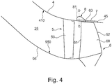
- the Figure 4 shows a sectional view of a structural assembly that defines a flow path 25 and includes an inlet stator 5, a rotor 6 and flow path boundaries.
- the flow path 25 conducts the core air flow A according to FIG Figure 1 through the core engine.
- the flow path 25 is delimited radially on the inside by inner wall or hub structures 95, which form an inner flow path boundary 950.
- the flow path 25 is delimited radially on the outside by a compressor housing 4 that forms a radially outer flow path boundary 410.
- the structural assembly is in the area of the first stage of a compressor.
- the compressor comprises the inlet guide wheel 5, which has stator blades 50 that can be adjusted in a staggered angle. The swirl in the flow is increased by the inlet guide wheel 5, and the subsequent rotor 6 is thereby striven for in a more effective manner.
- the rotor 6 comprises a series of rotor blades or rotor blades 60, which extend radially in the flow path 25.
- the blades 60 have a front edge 61, a rear edge 62 and a blade tip 63. A gap is realized between the blade tip 63 and the compressor housing 4.
- an inlet lining 7 is integrated in the compressor housing 4.
- the housing wall of the compressor housing 4 facing the flow path 25 forms a corresponding recess 45.
- the inlet lining 7 forms the flow path boundary 410.
- the inlet lining 7 is fastened in the recess 45 on its radially outer side.
- a housing structure 8 is integrated into the inlet lining 7. In the exemplary embodiment shown, this is implemented by axial grooves 81 in a half-heart shape.
- a such axial groove 81 in half-heart shape 81 is in the Figure 4 shown schematically.
- the illustration is not to be understood in such a way that the housing structuring 8 would protrude from the inlet lining 7 in the radial direction. The illustration only serves to display the axial course of the axial groove 81 in a half-heart shape.
- FIG. 5 shows a sectional view through a compressor housing 4 and an inlet lining 7 in a plane perpendicular to the axial direction, which is defined by the machine axis 9 (along the line DD of FIG Figure 4 ).
- the direction of rotation of the rotor 6 is marked with u.
- the compressor housing 4 has an upper compressor housing 410 and a lower compressor housing 420.
- the upper compressor housing 410 and the lower compressor housing 420 indicate spatial areas of the compressor housing 4. These are separated from one another by the horizontal plane 100.
- the upper compressor housing 410 and the lower compressor housing 420 can in principle be formed by any structures.
- the compressor housing comprises an upper peripheral segment 41 and a lower peripheral segment 42.
- the peripheral segments 41, 42 adjoin the flow path 25.
- the upper peripheral segment 41 extends, but not necessarily, in the region of the upper compressor housing 410.
- the lower peripheral segment 42 extends in the region of the lower compressor housing 420.
- the circumferential segments 41, 42 differ in any case in that only one of the circumferential segments forms a housing structure. It is thus provided that only the upper peripheral segment 41 has a housing structure 8, while the lower peripheral segment 42 has no housing structure.
- the housing structure in the illustrated embodiment is, but not necessarily in the inlet lining. Accordingly, the housing 4 has an upper inlet lining 71, in which a housing structure 8 is realized, and a lower inlet lining 72, which is realized without a housing structure.
- the two inlet linings 71, 72 each extend over 180 ° in the circumferential direction and adjoin one another in the horizontal plane 100.
- the housing 4 is a split housing which has two housing halves 411, 421, the division plane (ie the horizontal plane 100) between the two housing halves 411, 421 also representing the boundary between the two circumferential segments 41, 42 or inlet linings 71, 72.
- the upper inlet lining 71, in which a housing structure 8 is implemented, and the lower inlet lining 72, which is realized without a housing structure, consist, according to one embodiment, of the material Metco 601NS, Metco 320NS or Metco 314NS from Oerlikon Metco Switzerland in 8808 Pfäffikon, Switzerland , Metco 601 NS is a mixture of silicon-aluminum powders and polyester powders.
- Metco 320NS is an aluminum-silicon boron nitride powder.
- Metco 314NS is a thermal spray powder made from a nickel chrome aluminum bentonite mixture.
- high-temperature plastics, porous materials or metallic honeycomb structures are used as the material for the run-in coverings 71, 72.
- the radial thickness of the upper inlet lining 71 and the radial thickness of the lower inlet lining 72 are in any case identical in exemplary embodiments of the invention.
- the inlet linings 71, 72 are part of the compressor housing 4.
- the peripheral segments 41, 42 which are only partially provided with a housing structure, are shown in FIG Figure 5 formed by the inlet linings 71, 72 or in any case comprise these inlet linings 71, 72.
- the peripheral segments 41, 42 are formed by the actual compressor housing, ie the wall of the compressor housing facing the flow path 25.
- the corresponding structures such as axial grooves, are formed directly in the housing wall.
- the axial grooves 81 are shown in half-heart shape in a sectional view. As explained, the axial course of these axial grooves 81 is in the half-heart shape in FIG Figure 4 shown. According to the Figure 5 the axial grooves 81 are slightly inclined with respect to the radial direction. This can be done in one or the other circumferential direction. The axial grooves 81 can also run exactly in the radial direction.
- an inlet covering 72 is provided only in the lower circumferential segment 72.
- the casing structuring 8 is not realized in an upper inlet covering, but in an upper circumferential segment 41, which is through the casing wall of the compressor casing is realized. So that the flow path 25 does not have any cross-sectional change in such a case, it can be provided that the housing 4 has a larger housing radius in the lower compressor housing 420 than in the upper compressor housing 410 along the axial region in which it receives the lower inlet lining 72.
- neither the upper housing half 410 nor the lower housing half 420 has an inlet lining.
- a peripheral segment with a structuring of the housing is formed in the upper half of the housing.
- a peripheral segment without housing structuring is formed in the lower housing half.
- the Figure 6 shows a further embodiment of a structural assembly according to the present invention.
- the structural assembly comprises a compressor housing 4, which forms a flow path boundary 410.
- a rotor 6 comprises rotor blades 60, each of which has a front edge 61, a rear edge 62 and a blade tip 63. It can be seen that a gap is formed between the blade tip 63 and the flow path boundary 410.
- the machine axis 9 is also shown.
- a housing structure 8 is formed directly in the housing wall of the compressor housing 4 without the use of an inlet lining.
- a housing structure 8 is formed directly in the housing wall of the compressor housing 4 without the use of an inlet lining.
- formed by half-heart axial grooves 81 are in the DE 10 2007 056 953 A1 described, to which extent reference is made.
- the axial groove 81 with a half-heart shape can then be further defined by two angles ⁇ , ⁇ . These span the start and end of the cross-section curve specified by half the heart shape.
- the angle legs are arranged tangentially to the curve at the beginning or end.
- the angle ⁇ is, for example, in the range between 20 ° and 70 ° to the wall of the compressor housing and the angle ⁇ is, for example, in the range between 30 ° and 80 ° to the wall of the compressor housing.
- the Figure 6 furthermore shows that, in exemplary embodiments of the invention, the housing structure 8 in the region of the front edge 61 of the rotor blades 60 of the rotor 6 is formed.
- the axial extent of the axial grooves 81 is selected such that the axial grooves 81 extend from the front edge 630 of the blade tip 63 by a certain extension length opposite to the axial direction and from the front edge 630 by a certain extension length in the axial direction.
- the extension length in the two directions mentioned is, for example, a maximum of 50% of the axial length of the blade tip 63.
- Such an axial extension of the housing structuring can also be provided in the case of housing structuring designed in a different way.
- any of the features described can be used separately or in combination with any other features, provided that they are not mutually exclusive.
- the disclosure extends to and includes all combinations and subcombinations of one or more features described herein. If areas are defined, they include all values within these areas as well as all sub-areas that fall within one area.
Landscapes
- Engineering & Computer Science (AREA)
- Mechanical Engineering (AREA)
- General Engineering & Computer Science (AREA)
- Structures Of Non-Positive Displacement Pumps (AREA)
Abstract
Die Erfindung betrifft eine Strukturbaugruppe für einen Verdichter einer Strömungsmaschine, die ein Laufrad (6) mit einer Mehrzahl von Schaufeln (60), die sich in einem Strömungspfad (25) der Strömungsmaschine radial erstrecken, und ein Verdichtergehäuse (4) aufweist, das eine Strömungspfadberandung (410) ausbildet, die den Strömungspfad (25) durch die Strömungsmaschine radial außen begrenzt. Dabei weist das Verdichtergehäuse (4) angrenzend an das Laufrad (6) eine Gehäusestrukturierung (8) auf. Es ist vorgesehen, dass das Verdichtergehäuse (4) eine Mehrzahl von Umfangssegmenten (41, 42) aufweist, die sich in Umfangsrichtung erstrecken, wobei nur eines oder nur einige der Umfangssegmente (41) eine Gehäusestrukturierung (8) ausbilden.The invention relates to a structural assembly for a compressor of a turbomachine, which has an impeller (6) with a plurality of blades (60), which extend radially in a flow path (25) of the turbomachine, and a compressor housing (4), which has a flow path boundary (410) forms, which delimits the flow path (25) through the turbomachine radially on the outside. The compressor housing (4) has a housing structure (8) adjacent to the impeller (6). The compressor housing (4) has a plurality of peripheral segments (41, 42) which extend in the peripheral direction, only one or only some of the peripheral segments (41) forming a housing structure (8).
Description
Die Erfindung betrifft eine Strukturbaugruppe für einen Verdichter einer Strömungsmaschine gemäß dem Oberbegriff des Patentanspruchs 1.The invention relates to a structural assembly for a compressor of a turbomachine according to the preamble of claim 1.
Es ist grundsätzlich bekannt, Fans und Axialverdichter von Strömungsmaschinen mit einer Gehäusestrukturierung, auch als "Casing Treatment" bezeichnet, zu versehen. Zu einer solchen Gehäusestrukturierung sind eine Vielzahl von Bauformen bekannt, die den beiden Hauptgruppen umfangssymmetrisch (zum Beispiel in Form von Umfangsnuten) oder umfangsdiskret (zum Beispiel in Form von Axialnuten) zugeordnet werden. Ziel einer Gehäusestrukturierung ist es, den stabilen, d.h. stall- bzw. pumpfreien Arbeitsbereich des Verdichters zu erweitern.It is generally known to provide fans and axial compressors of turbomachines with a housing structure, also referred to as "casing treatment". A large number of designs are known for such a housing structuring, which are assigned to the two main groups in a circumferentially symmetrical manner (for example in the form of circumferential grooves) or discretely in circumference (for example in the form of axial grooves). The aim of structuring the housing is to ensure the stable, i.e. to expand the stall-free or pump-free working range of the compressor.
So ist es bekannt, dass die Schaufeln von Verdichtern eines Triebwerks nichtsymmetrische Schwingungen erfahren. Ein dabei auftretendes Phänomen ist als rotierende Ablösung ("rotating stall") bekannt (auch als Abreißflattern - "stall flutter" - bezeichnet). Bei der rotierenden Ablösung bilden sich an den Schaufelspitzen der Laufschaufeln instabile lokale Zellen, in denen die Strömung lokal abreißt. Diese Zellen können im rotierenden Bezugssystem in Umfangsrichtung entgegen dem Drehsinn des Schaufelrads wandern. Die rotierende Ablösung regt in nachteiliger Weise die einzelnen Schaufeln zu Schwingungen bzw. Vibrationen an, wodurch die Lebensdauer der Schaufeln reduziert wird. Auch ein Schaufelversagen infolge von Resonanz ist möglich, wenn die periodischen Anregungen im Bereich der Eigenschwingungen der Schaufeln liegen.It is known, for example, that the blades of compressors in an engine experience non-symmetrical vibrations. One phenomenon that occurs is known as rotating stall (also known as stall flutter). With the rotating detachment, unstable local cells form in the blade tips of the rotor blades, in which the flow breaks off locally. These cells can rotate in the circumferential direction against the direction of rotation Paddle wheel hiking. The rotating detachment disadvantageously excites the individual blades to oscillations or vibrations, as a result of which the service life of the blades is reduced. Blade failure due to resonance is also possible if the periodic excitations are in the region of the natural vibrations of the blades.
Aus der
Der Erfindung liegt die Aufgabe zu Grunde, eine Strukturbaugruppe für einen Verdichter einer Strömungsmaschine bereitzustellen, die in effektiver Weise eine Gehäusestrukturierung realisiert.The invention is based on the object of providing a structural assembly for a compressor of a turbomachine which effectively realizes a housing structuring.
Diese Aufgabe wird durch eine Strukturbaugruppe mit den Merkmalen des Patentanspruchs 1 gelöst. Ausgestaltungen der Erfindung sind in den abhängigen Ansprüchen angegeben.This object is achieved by a structural assembly with the features of patent claim 1. Embodiments of the invention are specified in the dependent claims.
Danach betrachtet die Erfindung eine Strukturbaugruppe für einen Verdichter einer Strömungsmaschine, die ein Laufrad mit einer Mehrzahl von Schaufeln aufweist, die sich in einem Strömungspfad der Strömungsmaschine radial erstrecken. Es ist ein Verdichtergehäuse vorgesehen, das eine Strömungspfadberandung ausbildet, die den Strömungspfad durch die Strömungsmaschine radial außen begrenzt. Das Verdichtergehäuse weist angrenzend an das Laufrad eine Gehäusestrukturierung auf. Eine Gehäusestrukturierung strukturiert die Strömungspfadberandung, d. h. den Wandbereich des Verdichtergehäuses, der den Strömungspfad begrenzt, wobei grundsätzlich beliebige, im Stand der Technik bekannte Gehäusestrukturierungen Einsatz finden können.The invention then considers a structural assembly for a compressor of a turbomachine that has an impeller with a plurality of blades that extend radially in a flow path of the turbomachine. A compressor housing is provided which forms a flow path boundary which delimits the flow path through the turbomachine radially on the outside. The compressor housing has a housing structure adjacent to the impeller. Housing structuring structures the flow path boundary, i. H. the wall area of the compressor housing, which delimits the flow path, it being possible in principle to use any housing structures known in the prior art.
Gemäß der vorliegenden Erfindung ist vorgesehen, dass das Verdichtergehäuse eine Mehrzahl von Umfangssegmenten aufweist, die sich in Umfangsrichtung erstrecken. Dabei bildet nur eines oder bilden nur einige der Umfangssegmente eine Gehäusestrukturierung aus, während die anderen Umfangssegmente ohne eine Gehäusestrukturierung ausgebildet sind. Ein Umfangssegment ist dabei ein sich in Umfangsrichtung erstreckendes Segment des Verdichtergehäuses, das an den Strömungspfad angrenzt. Die einzelnen Umfangssegmente schließen in Umfangsrichtung aneinander an. Mindestens ein Umfangssegment, aber nicht alle Umfangssegmente bilden dabei eine Gehäusestrukturierung aus, so dass das Verdichtergehäuse in Bezug auf die Gehäusestrukturierung Variationen aufweist.According to the present invention it is provided that the compressor housing has a plurality of circumferential segments which extend in the circumferential direction. Only one or only some of the peripheral segments form a housing structure, while the other peripheral segments are designed without a housing structure. A circumferential segment is a segment of the compressor housing which extends in the circumferential direction and which adjoins the flow path. The individual circumferential segments adjoin one another in the circumferential direction. At least one scope segment, but not all Circumferential segments form a housing structure, so that the compressor housing has variations with respect to the housing structure.
Die Erfindung wirkt wirksam einer rotierenden Ablösung entgegen. Die durch die Erfindung bereitgestellte Variation der Gehäusestrukturierung in Umfangsrichtung dahingehend, dass nur eines oder nur einige der Umfangssegmente eine Gehäusestrukturierung aufweisen, bewirkt, dass die Kohärenz der sich bildenden rotierenden Abrissmuster gestört wird. Dadurch wird einer lokal einsetzenden Strömungsablösung an den jeweiligen Schaufelspitzen entgegengewirkt. Die Erfindung unterdrückt somit die Ausbildung von kohärenten Ablösevorgängen an der Blattspitze und damit von Rotor-Schwingungen. Dadurch wird der stabile Arbeitsbereich des Verdichters und der Strömungsmaschine insgesamt signifikant vergrößert.The invention effectively counteracts rotating detachment. The variation of the housing structuring in the circumferential direction provided by the invention in such a way that only one or only some of the circumferential segments have a housing structuring has the effect that the coherence of the rotating demolition patterns that are formed is disturbed. This counteracts a locally occurring flow separation at the respective blade tips. The invention thus suppresses the formation of coherent separation processes at the blade tip and thus of rotor vibrations. This significantly increases the stable working range of the compressor and the turbomachine overall.
Eine Ausgestaltung der Erfindung sieht vor, dass das Verdichtergehäuse eine obere Gehäusehälfte und eine untere Gehäusehälfte aufweist, die sich jeweils in Umfangsrichtung über einen Umfangsbereich von 180° erstrecken, und dass das Umfangssegment oder die Umfangssegmente, die eine Gehäusestrukturierung ausbilden, in der oberen Gehäusehälfte des Verdichtergehäuses ausgebildet sind.One embodiment of the invention provides that the compressor housing has an upper housing half and a lower housing half, each of which extends in the circumferential direction over a circumferential region of 180 °, and that the circumferential segment or the circumferential segments which form a housing structure are in the upper housing half of the Compressor housing are formed.
Dieser Erfindungsaspekt sieht somit vor, die Gehäusestrukturierung nur in einem oder mehreren Umfangssegmenten vorzunehmen, die in der oberen Gehäusehälfte des Verdichtergehäuses ausgebildet sind. Hierdurch wird ein sicherer und effektiver Betrieb des Verdichters, in den die Strukturbaugruppe integriert ist, sichergestellt. Denn durch die Vermeidung einer Gehäusestrukturierung in der unteren Gehäusehälfte des Verdichtergehäuse wird die Gefahr vermieden, dass die Gehäusestrukturierung durch Eis verblockt wird, für welchen Fall ein zumindest temporärer Verlust der Funktionalität vorliegt.This aspect of the invention therefore provides for the housing to be structured only in one or more peripheral segments which are formed in the upper housing half of the compressor housing. This ensures safe and effective operation of the compressor in which the structural assembly is integrated. By avoiding a housing structuring in the lower housing half of the compressor housing, the risk is avoided that the housing structuring is blocked by ice, for which case there is an at least temporary loss of functionality.
Es wird darauf hingewiesen, dass die Aussage, dass das Verdichtergehäuse eine obere Gehäusehälfte und eine untere Gehäusehälfte aufweist, eine lediglich geometrische Aussage ist, die nichts über die Struktur des Verdichtergehäuse des bzw. der Gehäusehälfte aussagt. Die obere Gehäusehälfte ist der obere Bereich des Verdichtergehäuses und die untere Gehäusehälfte der untere Bereich des Verdichtergehäuse ist. Es kann sich um lediglich gedachte Bereiche handeln, wobei die beiden Bereiche durch eine horizontale Ebene voneinander getrennt sind. Die Begriffe "obere" und "untere" berücksichtigen dabei, dass sich die Strukturbaugruppe und das Verdichtergehäuse im Gravitationsfeld der Erde befinden, wodurch automatisch eine vertikale Richtung definiert ist. Ausgehend von einem Vektor, der entsprechend dem Gravitationsfeld nach unten zeigt und den Winkel von 0° definiert, erstreckt sich die obere Gehäusehälfte in einem Winkelbereich zwischen 90° und 270° und die untere Gehäusehälfte in einem Winkelbereich zwischen 270 und 90°.It is pointed out that the statement that the compressor housing has an upper housing half and a lower housing half is merely a geometric statement that does not say anything about the structure of the compressor housing of the housing half. The upper half of the housing is the upper region of the compressor housing and the lower half of the housing is the lower region of the compressor housing. It can only be imaginary areas, the two areas being separated from one another by a horizontal plane. The terms "upper" and "lower" take into account that the structural assembly and the compressor housing are in the gravitational field of the earth, which automatically results in a vertical direction is defined. Starting from a vector that points downwards according to the gravitational field and defines the angle of 0 °, the upper housing half extends in an angular range between 90 ° and 270 ° and the lower housing half in an angular range between 270 and 90 °.
Es wird weiter darauf hingewiesen, dass für den Fall, dass mehr als ein Umfangssegment eine Gehäusestrukturierung aufweist, die Umfangssegmente mit Gehäusestrukturierung unterschiedliche Gehäusestrukturierungen aufweisen können, wobei natürlich auch eine identische Gehäusestrukturierung vorgesehen sein kann. Ausführungsbeispiele sehen vor, dass mehrere aneinandergrenzende Umfangssegmente mit unterschiedlicher Gehäusestrukturierung ausgebildet sind, beispielsweise in der oberen Gehäusehälfte, oder dass mehrere durch Bereiche ohne Gehäusestrukturierung getrennte Umfangssegmente mit Gehäusestrukturierung ausgebildet sind.It is further pointed out that in the event that more than one peripheral segment has a housing structure, the peripheral segments with the housing structure can have different housing structures, and of course an identical housing structure can also be provided. Exemplary embodiments provide that a plurality of adjoining circumferential segments are formed with different housing structuring, for example in the upper housing half, or that a plurality of circumferential segments with housing structuring are separated by regions without housing structuring.
Eine Ausgestaltung der Erfindung sieht vor, dass die Umfangssegmente den gleichen Erstreckungswinkel in Umfangsrichtung aufweisen. Dies ist jedoch nicht notwendigerweise der Fall. In Ausgestaltungen der Erfindung kann vorgesehen sein, dass die Erstreckung der Umfangssegmente in Umfangsrichtung, also der Erstreckungswinkel variiert.One embodiment of the invention provides that the peripheral segments have the same extension angle in the peripheral direction. However, this is not necessarily the case. In embodiments of the invention, it can be provided that the extent of the circumferential segments varies in the circumferential direction, that is to say the extent angle.
Die Abfolge der Umfangssegmente kann des Weiteren umfangssymmetrisch oder umfangsasymmetrisch erfolgen, wobei Umfangsasymmetrie bedeutet, dass außer den Winkeln 0° und 360° keine Winkel existieren, bei denen die Abfolge der Umfangssegmente bei einer Drehung auf sich selbst abgebildet wird, d.h. zu einer gleichen Gesamtstrukturierung führt.The sequence of the circumferential segments can furthermore be circumferentially symmetrical or circumferentially asymmetrical, whereby circumferential asymmetry means that apart from the angles 0 ° and 360 ° there are no angles at which the sequence of the circumferential segments is mapped onto itself during a rotation, i.e. leads to the same overall structuring.
Eine Ausgestaltung der Erfindung sieht vor, dass das Verdichtergehäuse genau zwei Umfangssegmente aufweist, wobei ein oberes Umfangssegment in der oberen Gehäusehälfte und ein unteres Umfangssegment in der unteren Gehäusehälfte ausgebildet ist. Dabei ist die Gehäusestrukturierung ausschließlich in dem oberen Umfangssegment ausgebildet. Eine Ausführungsvariante hierzu kann vorsehen, dass beide Umfangssegmente sich jeweils über einen Umfangswinkel von 180° erstrecken. Dies ist jedoch nicht notwendigerweise der Fall. Beispielsweise kann vorgesehen sein, dass das obere Umfangssegment, das eine Gehäusestrukturierung ausbildet, sich über mehr oder weniger als 180° in Umfangsrichtung erstreckt, während das untere Umfangssegment sich dementsprechend über weniger oder mehr als 180° in Umfangsrichtung erstreckt.One embodiment of the invention provides that the compressor housing has exactly two peripheral segments, an upper peripheral segment being formed in the upper housing half and a lower peripheral segment being formed in the lower housing half. The housing structure is formed exclusively in the upper peripheral segment. An embodiment variant can provide that both circumferential segments each extend over a circumferential angle of 180 °. However, this is not necessarily the case. For example, it can be provided that the upper circumferential segment, which forms a housing structure, extends over more or less than 180 ° in the circumferential direction, while the lower circumferential segment accordingly extends over less or more than 180 ° in the circumferential direction.
Sofern beide Umfangssegmente sich jeweils über einen Umfangswinkel von 180° erstrecken, sind die beiden Umfangssegmente des Verdichtergehäuses zumindest näherungsweise als Halbzylinder ausgebildet.If both circumferential segments each extend over a circumferential angle of 180 °, the two circumferential segments of the compressor housing are at least approximately designed as half cylinders.
Gemäß einer Ausgestaltung der Erfindung ist das Verdichtergehäuse durch ein zweigeteiltes Gehäuse gebildet, das zwei Teile ausbildet, die sich jeweils über 180° in Umfangsrichtung erstrecken. Ein solches Verdichtergehäuse wird auch als "split casing" gezeichnet. Im Falle der Ausbildung des Verdichtergehäuse durch ein zweigeteiltes Gehäuse bietet sich in besonderem Maße an, dass das Verdichtergehäuse zwei Umfangssegmente mit einem Umfangswinkel von jeweils 180° aufweist, wobei die Teilungsebene zwischen den beiden Teilen des Verdichtergehäuse gleichzeitig die Grenze zwischen den beiden Umfangssegmente mit und ohne Gehäusestrukturierung darstellt. Es kann jedoch auch vorgesehen sein, dass zwei Umfangssegmente mit einem Umfangswinkel von jeweils 180° bei Verdichtergehäusen ausgebildet sind, die nicht zweigeteilt sind.According to one embodiment of the invention, the compressor housing is formed by a two-part housing which forms two parts which each extend over 180 ° in the circumferential direction. Such a compressor housing is also drawn as a "split casing". In the case of the compressor housing being formed by a two-part housing, it is particularly advantageous that the compressor housing has two circumferential segments with a circumferential angle of 180 ° in each case, the division plane between the two parts of the compressor housing simultaneously the boundary between the two circumferential segments with and without Representing housing structuring. However, it can also be provided that two circumferential segments with a circumferential angle of 180 ° are formed in the case of compressor housings that are not divided into two.
Eine weitere Ausgestaltung der Erfindung sieht vor, dass mindestens ein Umfangssegment des Verdichtergehäuses einen Einlaufbelag aufweist. Der Einlaufbelag bildet dabei die Strömungspfadberandung des Verdichtergehäuse. Im Sinne der vorliegenden Erfindung ist der Einlaufbelag Teil des Verdichtergehäuses. Die Verwendung eines Einlaufbelags, auch als Anstreifbelag oder "Liner" bezeichnet, ermöglicht enge Laufspalte zwischen den Spitzen der Rotorschaufeln und dem umgebenden Gehäuse, wodurch gute Verdichter-Leistungswerte erzielt werden können.A further embodiment of the invention provides that at least one peripheral segment of the compressor housing has an inlet lining. The inlet lining forms the boundary of the flow path of the compressor housing. In the sense of the present invention, the inlet lining is part of the compressor housing. The use of a run-in pad, also known as a rub-on pad or "liner", enables narrow running gaps between the tips of the rotor blades and the surrounding housing, as a result of which good compressor performance values can be achieved.
Dabei sind eine Vielzahl von Varianten möglich. Gemäß einer Variante weist zumindest ein Umfangssegment, das eine Gehäusestrukturierung aufweist, einen Einlaufbelag auf, wobei die Gehäusestrukturierung in dem Einlaufbelag ausgebildet ist. Dies ist mit dem Vorteil verbunden, dass die Gehäusestrukturierung nicht an dem eigentlichen Verdichtergehäuse (also in der metallischen Gehäusewand des Verdichtergehäuses), sondern an dem Einlaufbelag erfolgen kann. Hierdurch kann in einfacher Weise eine Gehäusestrukturierung bereitgestellt werden.A large number of variants are possible. According to a variant, at least one circumferential segment that has a housing structure has an inlet lining, the housing structure being formed in the inlet lining. This is associated with the advantage that the casing structuring cannot take place on the actual compressor casing (ie in the metallic casing wall of the compressor casing), but on the inlet lining. In this way, a housing structure can be provided in a simple manner.
Dabei kann vorgesehen sein, dass das obere Umfangssegment einen Einlaufbelag aufweist, der eine Gehäusestrukturierung ausbildet, und das untere Umfangssegment einen Einlaufbelag ohne Gehäusestrukturierung ausbildet. Hierdurch werden entlang des gesamten Umfangs des Verdichtergehäuses enge Laufspalte zwischen den Schaufelspitzen und der Strömungspfadbegrenzung erreicht.It can be provided that the upper circumferential segment has an inlet lining which forms a housing structure and the lower circumferential segment forms an inlet surface without a housing structure. This will along the The entire circumference of the compressor housing has narrow running gaps between the blade tips and the flow path limitation.
Eine weitere Variante sieht vor, dass nur das Umfangssegment oder nur die Umfangssegmente, die keine Gehäusestrukturierung ausbilden, einen Einlaufbelag aufweisen, während die Gehäusestrukturierung am eigentlichen Verdichtergehäuse, d.h. in der Gehäusewand des Verdichtergehäuses ausgebildet ist.Another variant provides that only the peripheral segment or only the peripheral segments that do not form a housing structure have an inlet lining, while the housing structure on the actual compressor housing, i.e. is formed in the housing wall of the compressor housing.
Für den Fall, dass nur eines oder nur einige der Umfangssegmente einen Einlaufbelag aufweisen, kann vorgesehen sein, dass die Umfangsegmente zwei unterschiedliche Gehäuseradien aufweisen (wobei der Gehäuseradius sich auf die Gehäusewand des eigentlichen Verdichtergehäuses und nicht auf den Radius des Einlaufbelags bezieht). Dabei ist der Gehäuseradius eines Umfangssegments, das einen Einlaufbelag aufweist, größer als der Gehäuseradius eines Umfangsegments, das keinen Einlaufbelag aufweist. Durch Umfangssegmente mit unterschiedlichen Radien kann erreicht werden, dass trotz des Umstands, dass ein Einlaufbelag nur in Teilsegmenten und nicht über 360° im Verdichtergehäuse ausgebildet ist, ein einheitlicher Radius der radial äußeren Strömungspfadbegrenzung realisiert ist.In the event that only one or only some of the peripheral segments have an inlet lining, it can be provided that the peripheral segments have two different housing radii (the housing radius referring to the housing wall of the actual compressor housing and not to the radius of the inlet lining). The radius of the housing of a peripheral segment that has an inlet lining is larger than the housing radius of a peripheral segment that has no inlet lining. By means of circumferential segments with different radii, it is possible to achieve a uniform radius of the radially outer flow path limitation despite the fact that an inlet lining is only formed in partial segments and not over 360 ° in the compressor housing.
Die Gehäusestrukturierung ist in einer Ausgestaltung umfangsdiskret ausgebildet und weist bei dieser Ausgestaltung beispielsweise Umfangsnuten auf, die sich jeweils in Umfangsrichtung erstrecken, wobei die Umfangsnuten in axialer Richtung beabstandet sind.In one configuration, the housing structuring is designed to be circumferentially discrete and, in this configuration, has circumferential grooves, for example, which each extend in the circumferential direction, the circumferential grooves being spaced apart in the axial direction.
Gemäß einer weiteren Ausgestaltung ist die Gehäusestrukturierung umfangsdiskret ausgebildet. Sie weist bei dieser Ausgestaltung beispielsweise Axialnuten auf, die sich jeweils über eine definierte Länge in axialer Richtung erstrecken, wobei die Axialnuten in Umfangsrichtung beabstandet sind. Eine Ausführungsvariante hierzu sieht vor, dass die Gehäusestrukturierung in Form von Halbherz-Axialnuten ausgebildet ist. Eine Gehäusestrukturierung in Form von Halbherz-Axialnuten ist beispielsweise aus der
In weiteren Varianten sind die Umfangsnuten oder Axialnuten mit rechteckigem oder parallelogrammförmigem Querschnitt vorgesehen. Auch kann vorgesehen sein, dass die Gehäusestrukturierung über Rezirkulationskanäle anstatt von Nuten erfolgt. Dabei ist vorgesehen, dass ein Rezirkulationskanal an der Strömungspfadberandung zwei Öffnungen miteinander verbindet, nämlich eine Entnahmeöffnung mit einer weiter stromauf vorgesehene Zuführöffnung. Solche Zirkulationskanäle sind beispielsweise aus der
Das Laufrad der erfindungsgemäß betrachteten Strukturbaugruppe kann ein Fan, das Laufrad eines Niederdruckverdichters, das Laufrad eines Mitteldruckverdichters oder das Laufrad eines Hochdruckverdichters sein. Es kann durch die erste Stufe (Verdichtereingangsstufe) oder eine eingebettete Stufe des Verdichters gebildet sein.The impeller of the structural assembly considered according to the invention can be a fan, the impeller of a low-pressure compressor, the impeller of a medium-pressure compressor or the impeller of a high-pressure compressor. It can be formed by the first stage (compressor input stage) or an embedded stage of the compressor.
Dabei kann vorgesehen sein, dass das Laufrad in BLISK-Bauweise ausgebildet. Bei Laufrädern in BLISK-Bauweise ergeben sich in besonderem Maße Probleme durch eine rotierende Ablösung, denen durch die vorliegende Erfindung entgegengewirkt wird.It can be provided that the impeller is designed in a BLISK design. In the case of BLISK-type wheels, problems arise due to a rotating detachment, which are counteracted by the present invention.
Ein Ausführungsbeispiel sieht vor, dass das Laufrad ein in BLISK-Bauweise ausgebildeter Fan ist.One embodiment provides that the impeller is a BLISK-designed fan.
Ein weiteres Ausführungsbeispiel sieht vor, dass das Laufrad ein in BLISK-Bauweise ausgebildetes Laufrad einer Verdichtereingangsstufe eines Verdichters ist. Eine solche Verdichtereingangsstufe umfasst des Weiteren einen Stator mit im Staffelungswinkel verstellbaren Statorschaufeln, der vor dem ersten Rotors des Verdichters angeordnet ist. Ein solcher Stator wird als Eintrittsleitrad oder Vorleitrad bzw. als IGV (IGV - Inlet Guide Vane) bezeichnet. Eintrittsleiträder erhöhen den Drall in der Strömung und verbessern den Arbeitsbereich eines Verdichters. In Verbindung mit der Bereitstellung einer Umfangsstrukturierung nur in Umfangssegmenten erfolgt in besonderem Maße eine Erweiterung des Arbeitsbereichs des Verdichters.Another exemplary embodiment provides that the impeller is a BLISK-type impeller of a compressor input stage of a compressor. Such a compressor input stage further comprises a stator with stator blades adjustable in staggering angle, which is arranged in front of the first rotor of the compressor. Such a stator is referred to as an inlet guide vane or a guide vane or as an IGV (IGV - Inlet Guide Vane). Inlet idlers increase the swirl in the flow and improve the working range of a compressor. In connection with the provision of a circumferential structure only in circumferential segments, the work area of the compressor is expanded to a particular extent.
Eine weitere Ausgestaltung der Erfindung sieht vor, dass die Gehäusestrukturierung angrenzend an die Vorderkante der Laufschaufeln im Verdichtergehäuse ausgebildet ist. Sie erstreckt sich dabei in einem Bereich, der bezogen auf die axiale Richtung vor der Vorderkante der Laufschaufeln beginnt und hinter der Vorderkante der Laufschaufeln endet.Another embodiment of the invention provides that the housing structure is formed adjacent to the front edge of the blades in the compressor housing. It extends in a region that begins in front of the front edge of the blades in relation to the axial direction and ends behind the front edge of the blades.
In einem weiteren Erfindungsaspekt stellt die Erfindung eine Strukturbaugruppe für einen Verdichter einer Strömungsmaschine bereit, die aufweist:
- ein in BLISK-Bauweise ausgebildetes Laufrad mit einer Mehrzahl von Schaufeln, die sich in einem Strömungspfad der Strömungsmaschine radial erstrecken,
- ein Verdichtergehäuse, das eine Strömungspfadberandung ausbildet, die den Strömungspfad durch die Strömungsmaschine radial außen begrenzt, wobei
- das Verdichtergehäuse eine obere Gehäusehälfte und eine untere Gehäusehälfte aufweist, die sich jeweils in Umfangsrichtung über einen Umfangsbereich von 180° erstrecken,
- das Verdichtergehäuse angrenzend an das Laufrad eine Gehäusestrukturierung aufweist,
- das Verdichtergehäuse zwei Umfangssegmente aufweist, die sich jeweils über einen Umfangswinkel von 180° erstrecken, wobei ein oberes Umfangssegment in der oberen Gehäusehälfte und ein unteres Umfangssegment in der unteren Gehäusehälfte ausgebildet ist,
- wobei die Gehäusestrukturierung ausschließlich in dem oberen Umfangssegment ausgebildet ist.
- a BLISK-type impeller with a plurality of blades that extend radially in a flow path of the turbomachine,
- a compressor housing that forms a flow path boundary that delimits the flow path through the turbomachine radially on the outside, wherein
- the compressor housing has an upper housing half and a lower housing half, each of which extends in the circumferential direction over a circumferential region of 180 °,
- the compressor housing has a housing structure adjacent to the impeller,
- the compressor housing has two circumferential segments, each of which extends over a circumferential angle of 180 °, an upper circumferential segment being formed in the upper half of the housing and a lower circumferential segment in the lower half of the housing,
- wherein the housing structure is formed exclusively in the upper peripheral segment.
In einem weiteren Erfindungsaspekt betrifft die Erfindung ein Gasturbinentriebwerk, insbesondere für ein Luftfahrzeug, mit einer erfindungsgemäßen Strukturbaugruppe. Dabei kann vorgesehen sein, dass das Gasturbinentriebwerk aufweist:
- einen Triebwerkskern, der eine Turbine, einen Verdichter mit einer erfindungsgemäßen Strukturbaugruppe und eine die Turbine mit dem Verdichter verbindende, als Hohlwelle ausgebildete Turbinenwelle umfasst;
- einen Fan, der stromaufwärts des Triebwerkskerns positioniert ist, wobei der Fan mehrere Fanschaufeln umfasst; und
- ein Getriebe, das einen Eingang von der Turbinenwelle empfängt und Antrieb für den Fan zum Antreiben des Fans mit einer niedrigeren Drehzahl als die Turbinenwelle abgibt.
- an engine core which comprises a turbine, a compressor with a structural assembly according to the invention and a turbine shaft which is designed as a hollow shaft and connects the turbine to the compressor;
- a fan positioned upstream of the engine core, the fan comprising a plurality of fan blades; and
- a transmission that receives an input from the turbine shaft and drives the fan to drive the fan at a lower speed than the turbine shaft.
Eine Ausgestaltung hierzu kann vorsehen, dass
- die Turbine eine erste Turbine ist, der Verdichter ein erster Verdichter ist und die Turbinenwelle eine erste Turbinenwelle ist;
- der Triebwerkskern ferner eine zweite Turbine, einen zweiten Verdichter und eine zweite Turbinenwelle, die die zweite Turbine mit dem zweiten Verdichter verbindet, umfasst; und
- die zweite Turbine, der zweite Verdichter und die zweite Turbinenwelle dahingehend angeordnet sind, sich mit einer höheren Drehzahl als die erste Turbinenwelle zu drehen.
- the turbine is a first turbine, the compressor is a first compressor, and the turbine shaft is a first turbine shaft;
- the engine core further includes a second turbine, a second compressor, and a second turbine shaft connecting the second turbine to the second compressor; and
- the second turbine, the second compressor, and the second turbine shaft are arranged to rotate at a higher speed than the first turbine shaft.
Es wird darauf hingewiesen, dass die vorliegende Erfindung bezogen auf ein zylindrisches Koordinatensystem beschrieben ist, das die Koordinaten x, r und ϕ aufweist. Dabei gibt x die axiale Richtung, r die radiale Richtung und ϕ den Winkel in Umfangsrichtung an. Die axiale Richtung ist dabei identisch mit der Maschinenachse eines Gasturbinentriebwerks, in dem die Strukturbaugruppe angeordnet ist. Von der x-Achse ausgehend zeigt die radiale Richtung radial nach außen. Begriffe wie "vor", "hinter", "vordere" und "hintere" beziehen sich auf die axiale Richtung bzw. die Strömungsrichtung im Triebwerk. Begriffe wie "äußere" oder "innere" beziehen sich auf die radiale Richtung.It is pointed out that the present invention is described with reference to a cylindrical coordinate system which has the coordinates x, r and ϕ. X indicates the axial direction, r the radial direction and ϕ the angle in the circumferential direction. The axial direction is identical to the machine axis of a gas turbine engine in which the structural assembly is arranged. From the x-axis starting from, the radial direction points radially outwards. Terms such as "in front", "behind", "front" and "rear" refer to the axial direction or the direction of flow in the engine. Terms such as "outer" or "inner" refer to the radial direction.
Wie hier an anderer Stelle angeführt wird, kann sich die vorliegende Offenbarung auf ein Gasturbinentriebwerk beziehen. Solch ein Gasturbinentriebwerk kann einen Triebwerkskern umfassen, der eine Turbine, einen Brennraum, einen Verdichter und eine die Turbine mit dem Verdichter verbindende Kernwelle umfasst. Solch ein Gasturbinentriebwerk kann ein Gebläse (mit Gebläseschaufeln) umfassen, das stromaufwärts des Triebwerkskerns positioniert ist.As stated elsewhere herein, the present disclosure may relate to a gas turbine engine. Such a gas turbine engine may include an engine core that includes a turbine, a combustion chamber, a compressor, and a core shaft connecting the turbine to the compressor. Such a gas turbine engine may include a fan (with fan blades) positioned upstream of the engine core.
Anordnungen der vorliegenden Offenbarung können insbesondere, jedoch nicht ausschließlich, für Gebläse, die über ein Getriebe angetrieben werden, von Vorteil sein. Entsprechend kann das Gasturbinentriebwerk ein Getriebe umfassen, das einen Eingang von der Kernwelle empfängt und Antrieb für das Gebläse zum Antreiben des Gebläses mit einer niedrigeren Drehzahl als die Kernwelle abgibt. Der Eingang für das Getriebe kann direkt von der Kernwelle oder indirekt von der Kernwelle, beispielsweise über eine Stirnwelle und/oder ein Stirnzahnrad, erfolgen. Die Kernwelle kann mit der Turbine und dem Verdichter starr verbunden sein, so dass sich die Turbine und der Verdichter mit derselben Drehzahl drehen (wobei sich das Gebläse mit einer niedrigeren Drehzahl dreht).Arrangements of the present disclosure may be particularly, but not exclusively, advantageous for fans that are driven by a transmission. Accordingly, the gas turbine engine may include a transmission that receives an input from the core shaft and drives the fan to drive the fan at a lower speed than the core shaft. The input for the transmission can take place directly from the core shaft or indirectly from the core shaft, for example via a spur shaft and / or a spur gear. The core shaft may be rigidly connected to the turbine and compressor so that the turbine and compressor rotate at the same speed (with the fan rotating at a lower speed).
Das Gasturbinentriebwerk, das hier beschrieben und/oder beansprucht wird, kann eine beliebige geeignete allgemeine Architektur aufweisen. Beispielsweise kann das Gasturbinentriebwerk eine beliebige gewünschte Anzahl an Wellen, die Turbinen und Verdichter verbinden, beispielsweise eine, zwei oder drei Wellen, aufweisen. Lediglich beispielhaft kann die mit der Kernwelle verbundene Turbine eine erste Turbine sein, der mit der Kernwelle verbundene Verdichter kann ein erster Verdichter sein und die Kernwelle kann eine erste Kernwelle sein. Der Triebwerkskern kann ferner eine zweite Turbine, einen zweiten Verdichter und eine zweite Kernwelle, die die zweite Turbine mit dem zweiten Verdichter verbindet, umfassen. Die zweite Turbine, der zweite Verdichter und die zweite Kernwelle können dahingehend angeordnet sein, sich mit einer höheren Drehzahl als die erste Kernwelle zu drehen.The gas turbine engine described and / or claimed herein can have any suitable general architecture. For example, the gas turbine engine may have any desired number of shafts connecting turbines and compressors, for example one, two or three shafts. For example only, the turbine connected to the core shaft may be a first turbine, the compressor connected to the core shaft may be a first compressor, and the core shaft may be a first core shaft. The engine core may further include a second turbine, a second compressor, and a second core shaft connecting the second turbine to the second compressor. The second turbine, the second compressor, and the second core shaft may be arranged to rotate at a higher speed than the first core shaft.
Bei solch einer Anordnung kann der zweite Verdichter axial stromabwärts des ersten Verdichters positioniert sein. Der zweite Verdichter kann dahingehend angeordnet sein, Strömung von dem ersten Verdichter aufzunehmen (beispielsweise direkt aufzunehmen, beispielsweise über einen allgemein ringförmigen Kanal).With such an arrangement, the second compressor may be positioned axially downstream of the first compressor. The second compressor can be arranged To receive flow from the first compressor (for example, to take up directly, for example through a generally annular channel).
Das Getriebe kann dahingehend angeordnet sein, von der Kernwelle, die dazu konfiguriert ist, sich (beispielsweise im Gebrauch) mit der niedrigsten Drehzahl zu drehen, (beispielsweise die erste Kernwelle in dem obigen Beispiel) angetrieben zu werden. Beispielsweise kann das Getriebe dahingehend angeordnet sein, lediglich von der Kernwelle, die dazu konfiguriert ist, sich (beispielsweise im Gebrauch) mit der niedrigsten Drehzahl zu drehen, (beispielsweise nur von der ersten Kernwelle und nicht der zweiten Kernwelle bei dem obigen Beispiel) angetrieben zu werden. Alternativ dazu kann das Getriebe dahingehend angeordnet sein, von einer oder mehreren Wellen, beispielsweise der ersten und/oder der zweiten Welle in dem obigen Beispiel, angetrieben zu werden.The transmission may be arranged to be driven by the core shaft configured to rotate at the lowest speed (e.g., in use) (e.g., the first core shaft in the example above). For example, the transmission may be arranged to be driven only by the core shaft configured to rotate at the lowest speed (for example, in use) (for example, only the first core shaft and not the second core shaft in the example above) become. Alternatively, the transmission may be arranged to be driven by one or more shafts, for example the first and / or the second shaft in the example above.
Bei einem Gasturbinentriebwerk, das hier beschrieben und/oder beansprucht wird, kann ein Brennraum axial stromabwärts des Gebläses und des Verdichters (der Verdichter) vorgesehen sein. Beispielsweise kann der Brennraum direkt stromabwärts des zweiten Verdichters (beispielsweise an dessen Ausgang) liegen, wenn ein zweiter Verdichter vorgesehen ist. Als ein weiteres Beispiel kann die Strömung am Ausgang des Verdichters dem Einlass der zweiten Turbine zugeführt werden, wenn eine zweite Turbine vorgesehen ist. Der Brennraum kann stromaufwärts der Turbine (der Turbinen) vorgesehen sein.In a gas turbine engine described and / or claimed herein, a combustion chamber may be provided axially downstream of the blower and the compressor (s). For example, the combustion chamber can be located directly downstream of the second compressor (for example at the outlet thereof) if a second compressor is provided. As another example, the flow at the outlet of the compressor can be supplied to the inlet of the second turbine if a second turbine is provided. The combustion chamber can be provided upstream of the turbine (s).
Der oder jeder Verdichter (beispielsweise der erste Verdichter und der zweite Verdichter gemäß obiger Beschreibung) kann eine beliebige Anzahl an Stufen, beispielsweise mehrere Stufen, umfassen. Jede Stufe kann eine Reihe von Rotorschaufeln und eine Reihe von Statorschaufeln, bei denen es sich um variable Statorschaufeln (dahingehend, dass ihr Anstellwinkel variabel sein kann) handeln kann, umfassen. Die Reihe von Rotorschaufeln und die Reihe von Statorschaufeln können axial voneinander versetzt sein.The or each compressor (for example the first compressor and the second compressor as described above) can comprise any number of stages, for example several stages. Each stage can include a series of rotor blades and a series of stator blades, which can be variable stator blades (in that their angle of attack can be variable). The row of rotor blades and the row of stator blades can be axially offset from one another.
Die oder jede Turbine (beispielsweise die erste Turbine und die zweite Turbine gemäß obiger Beschreibung) kann eine beliebige Anzahl an Stufen, beispielsweise mehrere Stufen, umfassen. Jede Stufe kann eine Reihe von Rotorschaufeln und eine Reihe von Statorschaufeln umfassen. Die Reihe von Rotorschaufeln und die Reihe von Statorschaufeln können axial voneinander versetzt sein.The or each turbine (e.g., the first turbine and the second turbine as described above) may include any number of stages, for example multiple stages. Each stage can include a series of rotor blades and a series of stator blades. The row of rotor blades and the row of stator blades can be axially offset from one another.
Jede Gebläseschaufel kann mit einer radialen Spannweite definiert sein, die sich von einem Fuß (oder einer Nabe) an einer radial innenliegenden von Gas überströmten Stelle oder an einer Position einer Spannbreite von 0 % zu einer Spitze an einer Position einer Spannbreite von 100 % erstreckt. Das Verhältnis des Radius der Gebläseschaufel an der Nabe zu dem Radius der Gebläseschaufel an der Spitze kann weniger als (oder in der Größenordnung von): 0,4, 0,39, 0,38, 0,37, 0,36, 0,35, 0,34, 0,33, 0,32, 0,31, 0,3, 0,29, 0,28, 0,27, 0,26 oder 0,25 liegen. Das Verhältnis des Radius der Gebläseschaufel an der Nabe zu dem Radius der Gebläseschaufel an der Spitze kann in einem einschließenden Bereich liegen, der von zwei der Werte im vorhergehenden Satz begrenzt wird (d. h. die Werte können obere oder untere Grenzen bilden). Diese Verhältnisse können allgemeinhin als das Nabe-Spitze-Verhältnis bezeichnet werden. Der Radius an der Nabe und der Radius an der Spitze können beide an dem vorderen Randteil (oder dem axial am weitesten vorne liegenden Rand) der Schaufel gemessen werden. Das Nabe-Spitze-Verhältnis bezieht sich natürlich auf den von Gas überströmten Abschnitt der Gebläseschaufel, d. h. den Abschnitt, der sich radial außerhalb jeglicher Plattform befindet.Each fan blade may be defined with a radial span that extends from a foot (or hub) at a radially inner gas-flowed location or at a 0% span position to a tip at a 100% span position. The ratio of the radius of the fan blade on the hub to the radius of the fan blade on the tip may be less than (or on the order of): 0.4, 0.39, 0.38, 0.37, 0.36, 0, 35, 0.34, 0.33, 0.32, 0.31, 0.3, 0.29, 0.28, 0.27, 0.26 or 0.25. The ratio of the radius of the fan blade at the hub to the radius of the fan blade at the tip can be in an inclusive range limited by two of the values in the previous sentence (i.e. the values can form upper or lower limits). These ratios can be commonly referred to as the hub-to-tip ratio. The radius at the hub and the radius at the tip can both be measured at the front edge portion (or the axially most forward edge) of the blade. The hub-to-tip ratio, of course, refers to the portion of the fan blade over which gas flows, i.e. H. the section that is radially outside of any platform.
Der Radius des Gebläses kann zwischen der Mittellinie des Triebwerks und der Spitze der Gebläseschaufel an ihrem vorderen Rand gemessen werden. Der Durchmesser des Gebläses (der einfach das Doppelte des Radius des Gebläses sein kann) kann größer als (oder in der Größenordnung von): 250 cm (etwa 100 Inch), 260 cm, 270 cm (etwa 105 Inch), 280 cm (etwa 110 Inch), 290 cm (etwa 115 Inch), 300 cm (etwa 120 Inch), 310 cm, 320 cm (etwa 125 Inch), 330 cm (etwa 130 Inch), 340 cm (etwa 135 Inch), 350 cm, 360 cm (etwa 140 Inch), 370 cm (etwa 145 Inch), 380 cm (etwa 150 Inch) oder 390 cm (etwa 155 Inch) sein (liegen). Der Gebläsedurchmesser kann in einem einschließenden Bereich liegen, der von zwei der Werte im vorhergehenden Satz begrenzt wird (d. h. die Werte können obere oder untere Grenzen bilden).The radius of the fan can be measured between the center line of the engine and the tip of the fan blade at its front edge. The diameter of the blower (which can simply be twice the radius of the blower) can be greater than (or on the order of): 250 cm (about 100 inches), 260 cm, 270 cm (about 105 inches), 280 cm (about 110 inches), 290 cm (about 115 inches), 300 cm (about 120 inches), 310 cm, 320 cm (about 125 inches), 330 cm (about 130 inches), 340 cm (about 135 inches), 350 cm, About 360 cm (about 140 inches), 370 cm (about 145 inches), 380 cm (about 150 inches) or 390 cm (about 155 inches). The fan diameter can be in an inclusive range limited by two of the values in the previous sentence (i.e. the values can be upper or lower limits).
Die Drehzahl des Gebläses kann im Gebrauch variieren. Allgemein ist die Drehzahl geringer für Gebläse mit einem größeren Durchmesser. Lediglich als ein nicht einschränkendes Beispiel kann die Drehzahl des Gebläses bei Konstantgeschwindigkeitsbedingungen weniger als 2500 U/min, beispielsweise weniger als 2300 U/min, betragen. Lediglich als ein weiteres nicht einschränkendes Beispiel kann auch die Drehzahl des Gebläses bei Konstantgeschwindigkeitsbedingungen für ein Triebwerk mit einem Gebläsedurchmesser im Bereich von 250 cm bis 300 cm (beispielsweise 250 cm bis 280 cm) im Bereich von 1700 U/min bis 2500 U/min, beispielsweise im Bereich von 1800 U/min bis 2300 U/min, beispielsweise im Bereich von 1900 U/min bis 2100 U/min, liegen. Lediglich als ein weiteres nicht einschränkendes Beispiel kann die Drehzahl des Gebläses bei Konstantgeschwindigkeitsbedingungen für ein Triebwerk mit einem Gebläsedurchmesser im Bereich von 320 cm bis 380 cm in dem Bereich von 1200 U/min bis 2000 U/min, beispielsweise in dem Bereich von 1300 U/min bis 1800 U/min, beispielsweise in dem Bereich von 1400 U/min bis 1600 U/min, liegen.The speed of the fan can vary in use. In general, the speed is lower for fans with a larger diameter. For example only, as a non-limiting example, the fan speed may be less than 2500 rpm, for example less than 2300 rpm, under constant speed conditions. Just as another, non-limiting example, the speed of the fan under constant speed conditions for an engine with a fan diameter in the range from 250 cm to 300 cm (for example 250 cm to 280 cm) in the range from 1700 rpm to 2500 rpm, for example in the range from 1800 rpm to 2300 rpm, for example in the range from 1900 rpm to 2100 rpm. Just as another non-limiting example, the speed of the fan under constant speed conditions for an engine with a fan diameter in the range from 320 cm to 380 cm can be in the range from 1200 rpm to 2000 rpm, for example in the range from 1300 rpm. min to 1800 rpm, for example in the range from 1400 rpm to 1600 rpm.
Im Gebrauch des Gasturbinentriebwerks dreht sich das Gebläse (mit zugehörigen Gebläseschaufeln) um eine Drehachse. Diese Drehung führt dazu, dass sich die Spitze der Gebläseschaufel mit einer Geschwindigkeit USpitze bewegt. Die von den Gebläseschaufeln an der Strömung verrichtete Arbeit resultiert in einem Anstieg der Enthalpie dH der Strömung. Eine Gebläsespitzenbelastung kann als dH/USpitze 2 definiert werden, wobei dH der Enthalpieanstieg (beispielsweise der durchschnittliche 1-D-Enthalpieanstieg) über das Gebläse hinweg ist und USpitze die (Translations-) Geschwindigkeit der Gebläsespitze, beispielsweise an dem vorderen Rand der Spitze, ist (die als Gebläsespitzenradius am vorderen Rand multipliziert mit der Winkelgeschwindigkeit definiert werden kann). Die Gebläsespitzenbelastung bei Konstantgeschwindigkeitsbedingungen kann mehr als (oder in der Größenordnung von): 0,3, 0,31, 0,32, 0,33, 0,34, 0,35, 0,36, 0,37, 0,38, 0,39 oder 0,4 betragen (liegen) (wobei alle Einheiten in diesem Abschnitt Jkg-1K-1/(ms-1)2 sind). Die Gebläsespitzenbelastung kann in einem einschließenden Bereich liegen, der von zwei der Werte im vorhergehenden Satz begrenzt wird (d. h. die Werte können obere oder untere Grenzen bilden).When using the gas turbine engine, the blower (with associated blower blades) rotates about an axis of rotation. This rotation causes the tip of the fan blade to move at a speed U tip . The work performed by the fan blades on the flow results in an increase in the enthalpy dH of the flow. A blower tip load can be defined as dH / U tip 2 , where dH is the enthalpy increase (e.g. the average 1-D enthalpy increase) across the blower and U tip is the (translation) speed of the blower tip, e.g. at the front edge of the tip , (which can be defined as the blower tip radius at the front edge multiplied by the angular velocity). The blower peak load under constant speed conditions can be more than (or on the order of): 0.3, 0.31, 0.32, 0.33, 0.34, 0.35, 0.36, 0.37, 0.38 , 0.39 or 0.4 are (lie) (all units in this section being Jkg -1 K -1 / (ms -1 ) 2 ). The blower peak load can be in an inclusive range limited by two of the values in the previous sentence (ie the values can be upper or lower limits).
Gasturbinentriebwerke gemäß der vorliegenden Offenbarung können ein beliebiges gewünschtes Bypassverhältnis aufweisen, wobei das Bypassverhältnis als das Verhältnis des Massendurchsatzes der Strömung durch den Bypasskanal zu dem Massendurchsatz der Strömung durch den Kern bei Konstantgeschwindigkeitsbedingungen definiert wird. Bei einigen Anordnungen kann das Bypassverhältnis mehr als (in der Größenordnung von): 10, 10,5, 11, 11,5, 12, 12,5, 13, 13,5, 14, 14,5, 15, 15,5, 16, 16,5 oder 17 betragen (liegen). Das Bypassverhältnis kann in einem einschließenden Bereich liegen, der von zwei der Werte im vorhergehenden Satz begrenzt wird (d. h. die Werte können obere oder untere Grenzen bilden). Der Bypasskanal kann im Wesentlichen ringförmig sein. Der Bypasskanal kann sich radial außerhalb des Triebwerkskerns befinden. Die radial äußere Fläche des Bypasskanals kann durch eine Triebwerksgondel und/oder ein Gebläsegehäuse definiert werden.Gas turbine engines in accordance with the present disclosure may have any desired bypass ratio, the bypass ratio being defined as the ratio of the mass flow rate of flow through the bypass channel to the mass flow rate of flow through the core at constant speed conditions. In some arrangements, the bypass ratio can be more than (on the order of): 10, 10.5, 11, 11.5, 12, 12.5, 13, 13.5, 14, 14.5, 15, 15.5 , 16, 16.5 or 17 are (lie). The bypass ratio can be in an inclusive range limited by two of the values in the previous sentence (ie the values can form upper or lower limits). The bypass channel can be essentially ring-shaped. The bypass channel can be located radially outside of the engine core. The radially outer surface of the bypass duct can be defined by an engine nacelle and / or a blower housing.
Das Gesamtdruckverhältnis eines Gasturbinentriebwerks, das hier beschrieben und/oder beansprucht wird, kann als das Verhältnis des Staudrucks stromaufwärts des Gebläses zu dem Staudruck am Ausgang des Höchstdruckverdichters (vor dem Eingang in den Brennraum) definiert werden. Als ein nicht einschränkendes Beispiel kann das Gesamtdruckverhältnis eines Gasturbinentriebwerks, das hier beschrieben und/oder beansprucht wird, bei Konstantgeschwindigkeit mehr als (oder in der Größenordnung von): 35, 40, 45, 50, 55, 60, 65, 70, 75 betragen (liegen). Das Gesamtdruckverhältnis kann in einem einschließenden Bereich liegen, der von zwei der Werte im vorhergehenden Satz begrenzt wird (d. h. die Werte können obere oder untere Grenzen bilden).The total pressure ratio of a gas turbine engine described and / or claimed herein can be defined as the ratio of the back pressure upstream of the fan to the back pressure at the output of the supercharger (prior to entering the combustion chamber). As a non-limiting example, the total pressure ratio of a gas turbine engine described and / or claimed herein at constant speed may be more than (or on the order of): 35, 40, 45, 50, 55, 60, 65, 70, 75 (lie). The total pressure ratio can be in an inclusive range limited by two of the values in the previous sentence (i.e. the values can be upper or lower limits).
Der spezifische Schub eines Triebwerks kann als der Nettoschub des Triebwerks dividiert durch den Gesamtmassenstrom durch das Triebwerk hindurch definiert werden. Bei Konstantgeschwindigkeitsbedingungen kann der spezifische Schub eines Triebwerks, das hier beschrieben und/oder beansprucht wird, weniger als (oder in der Größenordnung von): 110 Nkg-1s, 105 Nkg-1s, 100 Nkg-1s, 95 Nkg-1s, 90 Nkg-1s, 85 Nkg-1s oder 80 Nkg-1s betragen (liegen). Der spezifische Schub kann in einem einschließenden Bereich liegen, der von zwei der Werte im vorhergehenden Satz begrenzt wird (d. h. die Werte können obere oder untere Grenzen bilden). Solche Triebwerke können im Vergleich zu herkömmlichen Gasturbinentriebwerken besonders effizient sein.The specific thrust of an engine can be defined as the net thrust of the engine divided by the total mass flow through the engine. Under constant speed conditions, the specific thrust of an engine described and / or claimed herein may be less than (or on the order of): 110 Nkg -1 s, 105 Nkg -1 s, 100 Nkg -1 s, 95 Nkg -1 s, 90 Nkg -1 s, 85 Nkg -1 s or 80 Nkg -1 s. The specific thrust can be in an inclusive range limited by two of the values in the previous sentence (ie the values can be upper or lower limits). Such engines can be particularly efficient compared to conventional gas turbine engines.
Ein Gasturbinentriebwerk, das hier beschrieben und/oder beansprucht wird, kann einen beliebigen gewünschten Höchstschub aufweisen. Lediglich als ein nicht einschränkendes Beispiel kann eine Gasturbine, die hier beschrieben und/oder beansprucht wird, zur Erzeugung eines Höchstschubs von mindestens (oder in der Größenordnung von): 160kN, 170kN, 180kN, 190kN, 200kN, 250kN, 300kN, 350kN, 400kN, 450kN, 500kN oder 550kN in der Lage sein. Der Höchstschub kann in einem einschließenden Bereich liegen, der von zwei der Werte im vorhergehenden Satz begrenzt wird (d. h. die Werte können obere oder untere Grenzen bilden). Der Schub, auf den oben Bezug genommen wird, kann der Nettohöchstschub bei standardmäßigen atmosphärischen Bedingungen auf Meereshöhe plus 15 Grad C (Umgebungsdruck 101,3 kPa, Temperatur 30 Grad C) bei statischem Triebwerk sein.A gas turbine engine described and / or claimed herein can have any desired maximum thrust. By way of non-limiting example only, a gas turbine described and / or claimed herein can produce a maximum thrust of at least (or on the order of): 160kN, 170kN, 180kN, 190kN, 200kN, 250kN, 300kN, 350kN, 400kN , 450kN, 500kN or 550kN. The maximum thrust can be in an inclusive range limited by two of the values in the previous sentence (i.e. the values can be upper or lower limits). The thrust referred to above can be the maximum net thrust under standard atmospheric conditions at sea level plus 15 degrees C (ambient pressure 101.3 kPa,
Im Gebrauch kann die Temperatur der Strömung am Eingang der Hochdruckturbine besonders hoch sein. Diese Temperatur, die als TET bezeichnet werden kann, kann an dem Ausgang zum Brennraum, beispielsweise unmittelbar stromaufwärts der ersten Turbinenschaufel, die wiederum als eine Düsenleitschaufel bezeichnet werden kann, gemessen werden. Bei Konstantgeschwindigkeit kann die TET mindestens (oder in der Größenordnung von): 1400K, 1450K, 1500K, 1550K, 1600K oder 1650K betragen (liegen). Die TET bei Konstantgeschwindigkeit kann in einem einschließenden Bereich liegen, der von zwei der Werte im vorhergehenden Satz begrenzt wird (d. h. die Werte können obere oder untere Grenzen bilden). Die maximale TET im Gebrauch des Triebwerks kann beispielsweise mindestens (oder in der Größenordnung von): 1700K, 1750K, 1800K, 1850K, 1900K, 1950K oder 2000K betragen (liegen). Die maximale TET kann in einem einschließenden Bereich liegen, der von zwei der Werte im vorhergehenden Satz begrenzt wird (d. h. die Werte können obere oder untere Grenzen bilden). Die maximale TET kann beispielsweise bei einer Bedingung von hohem Schub, beispielsweise bei einer MTO-Bedingung (MTO - Maximum Take-Off thrust - maximaler Startschub), auftreten.In use, the temperature of the flow at the inlet of the high pressure turbine can be particularly high. This temperature, which can be referred to as TET, can be at the exit to the combustion chamber, for example immediately upstream of the first Turbine blade, which in turn can be referred to as a nozzle guide vane, are measured. At constant speed, the TET can be at least (or in the order of magnitude): 1400K, 1450K, 1500K, 1550K, 1600K or 1650K. The constant velocity TET can be in an inclusive range limited by two of the values in the previous sentence (ie the values can be upper or lower limits). For example, the maximum TET in use of the engine may be at least (or on the order of): 1700K, 1750K, 1800K, 1850K, 1900K, 1950K or 2000K. The maximum TET can be in an inclusive range limited by two of the values in the previous sentence (ie the values can be upper or lower limits). The maximum TET can occur, for example, in a condition of high thrust, for example an MTO condition (MTO - maximum take-off thrust - maximum start thrust).
Eine Gebläseschaufel und/oder ein Blattabschnitt einer Gebläseschaufel, die hier beschrieben und/oder beansprucht wird, kann aus einem beliebigen geeigneten Material oder einer Kombination aus Materialien hergestellt werden. Beispielsweise kann zumindest ein Teil der Gebläseschaufel und/oder des Blatts zumindest zum Teil aus einem Verbundstoff, beispielsweise einem Metallmatrix-Verbundstoff und/oder einem Verbundstoff mit organischer Matrix, wie z. B. Kohlefaser, hergestellt werden. Als ein weiteres Beispiel kann zumindest ein Teil der Gebläseschaufel und/oder des Blatts zumindest zum Teil aus einem Metall, wie z. B. einem auf Titan basierendem Metall oder einem auf Aluminium basierenden Material (wie z. B. einer Aluminium-Lithium-Legierung) oder einem auf Stahl basierenden Material hergestellt werden. Die Gebläseschaufel kann mindestens zwei Bereiche umfassen, die unter Verwendung verschiedener Materialien hergestellt werden. Beispielsweise kann die Gebläseschaufel einen vorderen Schutzrand aufweisen, der unter Verwendung eines Materials hergestellt wird, das dem Aufschlagen (beispielsweise von Vögeln, Eis oder anderem Material) besser widerstehen kann als der Rest der Schaufel. Solch ein vorderer Rand kann beispielsweise unter Verwendung von Titan oder einer auf Titan basierenden Legierung hergestellt werden. Somit kann die Gebläseschaufel lediglich als ein Beispiel einen auf Kohlefaser oder Aluminium basierenden Körper (wie z. B. eine Aluminium-Lithium-Legierung) mit einem vorderen Rand aus Titan aufweisen.A fan blade and / or a blade portion of a fan blade described and / or claimed herein can be made from any suitable material or combination of materials. For example, at least a part of the fan blade and / or the blade can be made at least in part of a composite, for example a metal matrix composite and / or a composite with an organic matrix, such as, for example. B. carbon fiber. As another example, at least a portion of the fan blade and / or the blade may be at least partially made of a metal, such as. B. a titanium-based metal or an aluminum-based material (such as an aluminum-lithium alloy) or a steel-based material. The fan blade may include at least two areas made using different materials. For example, the fan blade may have a protective front edge that is made using a material that is more resistant to impact (e.g., birds, ice, or other material) than the rest of the blade. Such a leading edge can be produced, for example, using titanium or a titanium-based alloy. Thus, as an example only, the fan blade may include a carbon fiber or aluminum based body (such as an aluminum-lithium alloy) with a titanium leading edge.
Ein Gebläse, das hier beschrieben und/oder beansprucht wird, kann einen mittleren Abschnitt umfassen, von dem sich die Gebläseschaufeln, beispielsweise in einer radialen Richtung, erstrecken können. Die Gebläseschaufeln können auf beliebige gewünschte Art und Weise an dem mittleren Abschnitt angebracht sein. Beispielsweise kann jede Gebläseschaufel eine Fixierungsvorrichtung umfassen, die mit einem entsprechenden Schlitz in der Nabe (oder Scheibe) in Eingriff gelangen kann. Lediglich als ein Beispiel kann solch eine Fixierungsvorrichtung in Form eines Schwalbenschwanzes vorliegen, der zur Fixierung der Gebläseschaufel an der Nabe/Scheibe in einen entsprechenden Schlitz in der Nabe/Scheibe eingesteckt und/oder damit in Eingriff gebracht werden kann. Als ein weiteres Beispiel können die Gebläseschaufeln integral mit einem mittleren Abschnitt ausgebildet sein. Solch eine Anordnung kann als eine Blisk oder ein Bling bezeichnet werden. Ein beliebiges geeignetes Verfahren kann zur Herstellung solch einer Blisk oder solch eines Bling verwendet werden. Beispielsweise kann zumindest ein Teil der Gebläseschaufeln aus einem Block maschinell herausgearbeitet werden und/oder mindestens ein Teil der Gebläseschaufeln kann durch Schweißen, wie z. B. lineares Reibschweißen, an der Nabe/Scheibe angebracht werden.A fan described and / or claimed herein may include a central portion from which the fan blades may extend, for example in a radial direction. The fan blades can be any desired Way to be attached to the middle section. For example, each fan blade can include a fixation device that can engage a corresponding slot in the hub (or disc). Such a fixing device in the form of a dovetail, which can be inserted and / or brought into engagement with a corresponding slot in the hub / disc for fixing the fan blade, can be present only as an example. As another example, the fan blades can be integrally formed with a central portion. Such an arrangement can be referred to as a blisk or a bling. Any suitable method can be used to make such a blisk or bling. For example, at least some of the fan blades can be machined out of a block and / or at least some of the fan blades can be welded, e.g. B. linear friction welding, attached to the hub / disc.
Die Gasturbinentriebwerke, die hier beschrieben und/oder beansprucht werden, können oder können nicht mit einer VAN (Variable Area Nozzle - Düse mit variablem Querschnitt) versehen sein. Solch eine Düse mit variablem Querschnitt kann eine Variation des Ausgangsquerschnitts des Bypasskanals im Gebrauch gestatten. Die allgemeinen Prinzipien der vorliegenden Offenbarung können auf Triebwerke mit oder ohne eine VAN zutreffen.The gas turbine engines described and / or claimed herein may or may not be provided with a VAN (Variable Area Nozzle - nozzle with a variable cross-section). Such a variable cross-section nozzle can allow the output cross-section of the bypass channel to be varied in use. The general principles of the present disclosure may apply to engines with or without a VAN.
Das Gebläse einer Gasturbine, die hier beschrieben und/oder beansprucht wird, kann eine beliebige gewünschte Anzahl an Gebläseschaufeln, beispielsweise 16, 18, 20 oder 22 Gebläseschaufeln, aufweisen.The blower of a gas turbine, which is described and / or claimed here, can have any desired number of blower blades, for example 16, 18, 20 or 22 blower blades.
Gemäß der hier erfolgenden Verwendung können Konstantgeschwindigkeitsbedingungen Konstantgeschwindigkeitsbedingungen eines Luftfahrzeugs, an dem das Gasturbinentriebwerk angebracht ist, bedeuten. Solche Konstantgeschwindigkeitsbedingungen können herkömmlicherweise als die Bedingungen während des mittleren Teils des Flugs definiert werden, beispielsweise die Bedingungen, denen das Luftfahrzeug und/oder das Triebwerk zwischen (hinsichtlich Zeit und/oder Entfernung) dem Ende des Steigflugs und dem Beginn des Sinkflugs ausgesetzt wird bzw. werden.As used herein, constant speed conditions may mean constant speed conditions of an aircraft to which the gas turbine engine is attached. Such constant speed conditions can conventionally be defined as the conditions during the middle part of the flight, for example the conditions to which the aircraft and / or the engine is exposed between (in terms of time and / or distance) the end of the climb and the start of the descent. become.
Lediglich als ein Beispiel kann die Vorwärtsgeschwindigkeit bei der Konstantgeschwindigkeitsbedingung bei einem beliebigen Punkt im Bereich von Mach 0,7 bis 0,9, beispielsweise 0,75 bis 0,85, beispielsweise 0,76 bis 0,84, beispielsweise 0,77 bis 0,83, beispielsweise 0,78 bis 0,82, beispielsweise 0,79 bis 0,81, beispielsweise in der Größenordnung von Mach 0,8, in der Größenordnung von Mach 0,85 oder in dem Bereich von 0,8 bis 0,85 liegen. Eine beliebige Geschwindigkeit innerhalb dieser Bereiche kann die Konstantfahrtbedingung sein. Bei einigen Luftfahrzeugen können die Konstantfahrtbedingungen außerhalb dieser Bereiche, beispielsweise unter Mach 0,7 oder über Mach 0,9, liegen.For example only, the forward speed in the constant speed condition at any point may range from Mach 0.7 to 0.9, for example 0.75 to 0.85, for example 0.76 to 0.84, for example 0.77 to 0.83, for example 0.78 to 0.82, for example 0.79 to 0.81, for example in the order of Mach 0.8, in the order of Mach 0.85 or in the range of 0 , 8 to 0.85. Any speed within these ranges can be the constant travel condition. For some aircraft, constant speed conditions may be outside of these ranges, for example below Mach 0.7 or above Mach 0.9.
Lediglich als ein Beispiel können die Konstantgeschwindigkeitsbedingungen standardmäßigen atmosphärischen Bedingungen bei einer Höhe, die im Bereich von 10.000 m bis 15.000 m, beispielsweise im Bereich von 10.000 m bis 12.000 m, beispielsweise im Bereich von 10.400 m bis 11.600 m (etwa 38.000 Fuß) beispielsweise im Bereich von 10.500 m bis 11.500 m, beispielsweise im Bereich von 10.600 m bis 11.400 m, beispielsweise im Bereich von 10.700 m (etwa 35.000 Fuß) bis 11.300 m, beispielsweise im Bereich von 10.800 m bis 11.200 m, beispielsweise im Bereich von 10.900 m bis 11.100 m, beispielsweise in der Größenordnung von 11.000 m, liegt, entsprechen. Die Konstantgeschwindigkeitsbedingungen können standardmäßigen atmosphärischen Bedingungen bei einer beliebigen gegebenen Höhe in diesen Bereichen entsprechen.For example only, the constant speed conditions may be standard atmospheric conditions at an altitude that is in the range of 10,000 m to 15,000 m, for example in the range of 10,000 m to 12,000 m, for example in the range of 10,400 m to 11,600 m (approximately 38,000 feet), for example in Range from 10,500 m to 11,500 m, for example in the range from 10,600 m to 11,400 m, for example in the range from 10,700 m (approximately 35,000 feet) to 11,300 m, for example in the range from 10,800 m to 11,200 m, for example in the range from 10,900 m to 11,100 m, for example in the order of 11,000 m, correspond. The constant speed conditions can correspond to standard atmospheric conditions at any given altitude in these areas.
Lediglich als ein Beispiel können die Konstantgeschwindigkeitsbedingungen Folgendem entsprechen: einer Vorwärts-Mach-Zahl von 0,8; einem Druck von 23.000 Pa und einer Temperatur von -55 Grad C.As an example only, the constant speed conditions may correspond to: a forward Mach number of 0.8; a pressure of 23,000 Pa and a temperature of -55 degrees C.
So wie sie hier durchweg verwendet werden, können "Konstantgeschwindigkeit" oder "Konstantgeschwindigkeitsbedingungen" den aerodynamischen Auslegungspunkt bedeuten. Solch ein aerodynamischer Auslegungspunkt (oder ADP - Aerodynamic Design Point) kann den Bedingungen (darunter beispielsweise die Mach-Zahl, Umgebungsbedingungen und Schubanforderung), für die der Gebläsebetrieb ausgelegt ist, entsprechen. Dies kann beispielsweise die Bedingungen, bei denen das Gebläse (oder das Gasturbinentriebwerk) konstruktionsgemäß den optimalen Wirkungsgrad aufweist, bedeuten.As used throughout, "constant speed" or "constant speed conditions" can mean the aerodynamic design point. Such an aerodynamic design point (or ADP - Aerodynamic Design Point) can correspond to the conditions (including, for example, the Mach number, ambient conditions and thrust requirement) for which the fan operation is designed. This can mean, for example, the conditions in which the blower (or the gas turbine engine) has the optimal efficiency by design.
Im Gebrauch kann ein Gasturbinentriebwerk, das hier beschrieben und/oder beansprucht wird, bei den Konstantgeschwindigkeitsbedingungen, die hier an anderer Stelle definiert werden, betrieben werden. Solche Konstantgeschwindigkeitsbedingungen können von den Konstantgeschwindigkeitsbedingungen (beispielsweise den Bedingungen während des mittleren Teils des Fluges) eines Luftfahrzeugs, an dem mindestens ein (beispielsweise 2 oder 4) Gasturbinentriebwerk zur Bereitstellung von Schubkraft befestigt sein kann, bestimmt werden.In use, a gas turbine engine described and / or claimed herein may be operated at the constant speed conditions defined elsewhere herein. Such constant speed conditions may differ from the constant speed conditions (e.g. conditions during the middle part of the flight) of an aircraft on which at least one (For example, 2 or 4) gas turbine engine may be attached to provide thrust.
Für den Fachmann ist verständlich, dass ein Merkmal oder Parameter, das bzw. der in Bezug auf einen der obigen Aspekte beschrieben wird, bei einem beliebigen anderen Aspekt angewendet werden kann, sofern sie sich nicht gegenseitig ausschließen. Des Weiteren kann ein beliebiges Merkmal oder ein beliebiger Parameter, das bzw. der hier beschrieben wird, bei einem beliebigen Aspekt angewendet werden und/oder mit einem beliebigen anderen Merkmal oder Parameter, das bzw. der hier beschrieben wird, kombiniert werden, sofern sie sich nicht gegenseitig ausschließen.It will be understood by those skilled in the art that a feature or parameter described in relation to one of the above aspects can be applied to any other aspect, unless they are mutually exclusive. Furthermore, any feature or parameter described here can be applied to any aspect and / or combined with any other feature or parameter described here, if they are not mutually exclusive.
Die Erfindung wird nachfolgend unter Bezugnahme auf die Figuren der Zeichnung anhand mehrerer Ausführungsbeispiele näher erläutert. Es zeigen:
- Figur 1
- eine Seitenschnittansicht eines Gasturbinentriebwerks;
- Figur 2
- eine Seitenschnittgroßansicht eines stromaufwärtigen Abschnitts eines Gasturbinentriebwerks;
- Figur 3
- eine zum Teil weggeschnitte Ansicht eines Getriebes für ein Gasturbinentriebwerk;
Figur 4- schematisch eine Strukturbaugruppe, die ein Eintrittsleitrad, ein Laufrad und ein Verdichtergehäuse mit einer Gehäusestrukturierung aufweist;
Figur 5- einen Schnitt senkrecht zur axialen Richtung entlang der Linie D-D der
Figur 4 ; und Figur 6- ein Ausführungsbeispiel einer Axialnut, die in Form einer Halbherz-Nut ausgebildet ist.
- Figure 1
- a sectional side view of a gas turbine engine;
- Figure 2
- a side sectional large view of an upstream portion of a gas turbine engine;
- Figure 3
- a partially cut-away view of a transmission for a gas turbine engine;
- Figure 4
- schematically a structural assembly, which has an inlet stator, an impeller and a compressor housing with a housing structure;
- Figure 5
- a section perpendicular to the axial direction along the line DD
Figure 4 ; and - Figure 6
- an embodiment of an axial groove, which is designed in the form of a half-heart groove.
Im Gebrauch wird der Kernluftstrom A durch den Niederdruckverdichter 14 beschleunigt und verdichtet und in den Hochdruckverdichter 15 geleitet, wo eine weitere Verdichtung erfolgt. Die aus dem Hochdruckverdichter 15 ausgestoßene verdichtete Luft wird in die Verbrennungseinrichtung 16 geleitet, wo sie mit Kraftstoff vermischt wird und das Gemisch verbrannt wird. Die resultierenden heißen Verbrennungsprodukte breiten sich dann durch die Hochdruck- und die Niederdruckturbine 17, 19 aus und treiben diese dadurch an, bevor sie zur Bereitstellung einer gewissen Schubkraft durch die Düse 20 ausgestoßen werden. Die Hochdruckturbine 17 treibt den Hochdruckverdichter 15 durch eine geeignete Verbindungswelle 27 an. Das Gebläse 23 stellt allgemein den Hauptteil der Schubkraft bereit. Das Epizykloidengetriebe 30 ist ein Untersetzungsgetriebe.In use, the core air flow A is accelerated and compressed by the
Eine beispielhafte Anordnung für ein Getriebegebläse-Gasturbinentriebwerk 10 wird in
Es wird angemerkt, dass die Begriffe "Niederdruckturbine" und "Niederdruckverdichter", so wie sie hier verwendet werden, so aufgefasst werden können, dass sie die Turbinenstufe mit dem niedrigsten Druck bzw. die Verdichterstufe mit dem niedrigsten Druck (d. h. dass sie nicht das Gebläse 23 umfassen) und/oder die Turbinen- und Verdichterstufe, die durch die Verbindungswelle 26 mit der niedrigsten Drehzahl in dem Triebwerk (d. h. dass sie nicht die Getriebeausgangswelle, die das Gebläse 23 antreibt, umfasst) miteinander verbunden sind, bedeuten. In einigen Schriften können die "Niederdruckturbine" und der "Niederdruckverdichter", auf die hier Bezug genommen wird, alternativ dazu als die "Mitteldruckturbine" und "Mitteldruckverdichter" bekannt sein. Bei der Verwendung derartiger alternativer Nomenklatur kann das Gebläse 23 als eine erste Verdichtungsstufe oder Verdichtungsstufe mit dem niedrigsten Druck bezeichnet werden.It is noted that the terms "low pressure turbine" and "low pressure compressor" as used herein can be understood to mean the lowest pressure turbine stage and the lowest pressure compressor stage (ie, they are not the blower 23) and / or the turbine and compressor stage connected by the lowest
Das Epizykloidengetriebe 30 wird in
Das in
Es versteht sich, dass die in
Entsprechend dehnt sich die vorliegende Offenbarung auf ein Gasturbinentriebwerk mit einer beliebigen Anordnung der Getriebearten (beispielsweise sternförmig oder planetenartig), Stützstrukturen, Eingangs- und Ausgangswellenanordnung und Lagerpositionierungen aus.Accordingly, the present disclosure extends to a gas turbine engine with an arbitrary arrangement of the transmission types (for example star-shaped or planet-like), support structures, input and output shaft arrangement and bearing positions.
Optional kann das Getriebe Neben- und/oder alternative Komponenten (z. B. den Mitteldruckverdichter und/oder einen Nachverdichter) antreiben.Optionally, the transmission can drive secondary and / or alternative components (e.g. the medium pressure compressor and / or a secondary compressor).
Andere Gasturbinentriebwerke, bei denen die vorliegende Offenbarung Anwendung finden kann, können alternative Konfigurationen aufweisen. Beispielsweise können derartige Triebwerke eine alternative Anzahl an Verdichtern und/oder Turbinen und/oder eine alternative Anzahl an Verbindungswellen aufweisen. Als ein weiteres Beispiel weist das in
Die Geometrie des Gasturbinentriebwerks 10 und Komponenten davon wird bzw. werden durch ein herkömmliches Achsensystem definiert, das eine axiale Richtung (die auf die Drehachse 9 ausgerichtet ist), eine radiale Richtung (in der Richtung von unten nach oben in
Im Kontext der vorliegenden Erfindung ist die Ausbildung einer Gehäusestrukturierung im Verdichtergehäuse von Bedeutung. Die Erfindung ist dabei grundsätzlich in der Fanstufe, in einem Niederdruckverdichter, einem Mitteldruckverdichter (sofern vorhanden) und/oder einem Hochdruckverdichter realisierbar.In the context of the present invention, the formation of a housing structure in the compressor housing is important. The invention can basically be implemented in the fan stage, in a low-pressure compressor, in a medium-pressure compressor (if present) and / or in a high-pressure compressor.
Die
Der Strömungspfad 25 wird radial innen durch innere Wand- oder Nabenstrukturen 95 begrenzt, die eine innere Strömungspfadberandung 950 ausbilden. Radial außen wird der Strömungspfad 25 durch ein Verdichtergehäuse 4 begrenzt, dass eine radial äußere Strömungspfadberandung 410 ausbildet. Im dargestellten Ausführungsbeispiel, jedoch nicht notwendigerweise, befindet sich die Strukturbaugruppe im Bereich der ersten Stufe eines Verdichters. Dabei umfasst der Verdichter das Eintrittsleitrad 5, das im Staffelungswinkel verstellbare Statorschaufeln 50 aufweist. Durch das Eintrittsleitrad 5 wird der Drall in der Strömung erhöht und dadurch der nachfolgende Rotor 6 in effektiverer Weise angestrebt.The
Der Rotor 6 umfasst eine Reihe von Rotorschaufeln bzw. Laufschaufeln 60, die sich im Strömungspfad 25 radial erstrecken. Die Laufschaufeln 60 weisen eine Vorderkante 61, eine Hinterkante 62 und eine Schaufelspitze 63 auf. Zwischen der Schaufelspitze 63 und dem Verdichtergehäuse 4 ist ein Spalt realisiert.The
Zur Minimierung dieses Spaltes ist in das Verdichtergehäuse 4 ein Einlaufbelag 7 integriert. Die dem Strömungspfad 25 zugewandte Gehäusewand des Verdichtergehäuses 4 bildet hierzu eine entsprechende Aussparung 45 auf. An seiner dem Strömungspfad 25 zugewandten Seite bildet der Einlaufbelag 7 die Strömungspfadberandung 410 aus. An seiner radial äußeren Seite ist der Einlaufbelag 7 in der Aussparung 45 befestigt.To minimize this gap, an inlet lining 7 is integrated in the
In den Einlaufbelag 7 ist eine Gehäusestrukturierung 8 integriert. Im dargestellten Ausführungsbeispiel ist diese durch Axialnuten 81 in Halbherz-Form realisiert. Eine solche Axialnut 81 in Halbherz-Form 81 ist in der
Ein weitergehendes Verständnis des Aufbaus der Gehäusestrukturierung 8 ergibt sich aus der
Zunächst wird terminologisch darauf hingewiesen, dass das Verdichtergehäuse 4 ein oberes Verdichtergehäuse 410 und ein unteres Verdichtergehäuse 420 aufweist. Das obere Verdichtergehäuse 410 und das untere Verdichtergehäuse 420 geben dabei räumliche Bereiche des Verdichtergehäuses 4 an. Diese sind durch die horizontale Ebene 100 voneinander getrennt. Das obere Verdichtergehäuse 410 und das untere Verdichtergehäuse 420 können grundsätzlich durch beliebige Strukturen gebildet sein.First, it is indicated terminologically that the
Wie in der
Die Umfangssegmente 41, 42 unterscheiden sich jedenfalls dadurch, dass nur eines der Umfangssegmente eine Gehäusestrukturierung ausbildet. So ist vorgesehen, dass lediglich das obere Umfangssegment 41 eine Gehäusestrukturierung 8 aufweist, während das untere Umfangssegment 42 keine Gehäusestrukturierung aufweist.The
Wie in Bezug auf die
Der obere Einlaufbelag 71, in dem eine Gehäusestrukturierung 8 realisiert ist, und der untere Einlaufbelag 72, der ohne eine Gehäusestrukturierung realisiert ist, bestehen gemäß einem Ausführungsbeispiel aus dem Material Metco 601NS, Metco 320NS oder Metco 314NS der Oerlikon Metco Switzerland in 8808 Pfäffikon, Schweiz. Metco 601 NS ist eine Mischung aus Silizium-Aluminium-Pulvern und Polyester-Pulvern. Metco 320NS ist ein Aluminium-Silizium Bornitrid Pulver. Metco 314NS ist ein thermisches Spritzpulver aus einer Nickel Chrom Aluminium Bentonit Mischung.The upper inlet lining 71, in which a
Alternativ werden als Material für die Einlaufbeläge 71, 72 hochtemperaturfähige Kunststoffe, poröse Materialien oder metallische Wabenstrukturen eingesetzt.Alternatively, high-temperature plastics, porous materials or metallic honeycomb structures are used as the material for the run-in
Die radiale Dicke des oberen Einlaufbelags 71 und die radiale Dicke des unteren Einlaufbelags 72 sind jedenfalls in Ausführungsbeispielen der Erfindung identisch.The radial thickness of the upper inlet lining 71 and the radial thickness of the lower inlet lining 72 are in any case identical in exemplary embodiments of the invention.
Entsprechend der verwendeten Terminologie sind die Einlaufbeläge 71, 72 Teil des Verdichtergehäuses 4. Die Umfangssegmente 41, 42, die nur teilweise mit einer Gehäusestrukturierung versehen sind, sind in der
In der
In einer Abwandlung des Ausführungsbeispiels der
In einer weiteren Abwandlung des Ausführungsbeispiels der
Die
Beim Ausführungsbeispiel der
Danach kann die Axialnut 81 mit Halbherz-Form weitergehend durch zwei Winkel α, β definiert werden. Diese spannen den Anfangsbereich und den Endbereich der durch die halbe Herzform vorgegebenen Querschnittskurve auf. Dabei sind die Winkelschenkel tangential zu dem anfangsseitigen bzw. endseitigen Kurvenverlauf angeordnet. Der Winkel α liegt beispielsweise im Bereich zwischen 20° und 70° zur Wand des Verdichtergehäuses und der Winkel β liegt beispielsweise im Bereich zwischen 30° und 80° zur Wand des Verdichtergehäuses.The
Die
Es versteht sich, dass die Erfindung nicht auf die oben beschriebenen Ausführungsformen beschränkt ist und verschiedene Modifikationen und Verbesserungen vorgenommen werden können, ohne von den hier beschriebenen Konzepten abzuweichen. Beispielsweise kann eine andere segmentale Aufteilung des Verdichtergehäuses vorgesehen sein.It is understood that the invention is not limited to the embodiments described above and various modifications and improvements can be made without departing from the concepts described here. For example, a different segmental division of the compressor housing can be provided.
Es wird weiter darauf hingewiesen, dass beliebige der beschriebenen Merkmale separat oder in Kombination mit beliebigen anderen Merkmalen eingesetzt werden können, sofern sie sich nicht gegenseitig ausschließen. Die Offenbarung dehnt sich auf alle Kombinationen und Unterkombinationen eines oder mehrerer Merkmale aus, die hier beschrieben werden und umfasst diese. Sofern Bereiche definiert sind, so umfassen diese sämtliche Werte innerhalb dieser Bereiche sowie sämtliche Teilbereiche, die in einen Bereich fallen.It is further pointed out that any of the features described can be used separately or in combination with any other features, provided that they are not mutually exclusive. The disclosure extends to and includes all combinations and subcombinations of one or more features described herein. If areas are defined, they include all values within these areas as well as all sub-areas that fall within one area.
Claims (15)
dass das Verdichtergehäuse (4) eine Mehrzahl von Umfangssegmenten (41, 42) aufweist, die sich in Umfangsrichtung erstrecken, wobei nur eines oder nur einige der Umfangssegmente (41) eine Gehäusestrukturierung (8) ausbilden.Structural assembly for a compressor of a turbomachine, which has:
that the compressor housing (4) has a plurality of peripheral segments (41, 42) which extend in the peripheral direction, only one or only some of the peripheral segments (41) forming a housing structure (8).
Applications Claiming Priority (1)
| Application Number | Priority Date | Filing Date | Title |
|---|---|---|---|
| DE102018116062.3A DE102018116062A1 (en) | 2018-07-03 | 2018-07-03 | Structure assembly for a compressor of a turbomachine |
Publications (2)
| Publication Number | Publication Date |
|---|---|
| EP3591237A1 true EP3591237A1 (en) | 2020-01-08 |
| EP3591237B1 EP3591237B1 (en) | 2021-05-19 |
Family
ID=67001586
Family Applications (1)
| Application Number | Title | Priority Date | Filing Date |
|---|---|---|---|
| EP19181591.9A Active EP3591237B1 (en) | 2018-07-03 | 2019-06-21 | Structural module for a compressor of a turbomachine |
Country Status (3)
| Country | Link |
|---|---|
| US (1) | US11131322B2 (en) |
| EP (1) | EP3591237B1 (en) |
| DE (1) | DE102018116062A1 (en) |
Cited By (7)
| Publication number | Priority date | Publication date | Assignee | Title |
|---|---|---|---|---|
| FR3107917A1 (en) * | 2020-03-04 | 2021-09-10 | Safran | Movable wheel housing for turbomachine |
| US12168983B1 (en) | 2024-06-28 | 2024-12-17 | Rolls-Royce North American Technologies Inc. | Active fan tip treatment using rotating drum array in fan track liner with axial and circumferential channels for distortion tolerance |
| US12209541B1 (en) | 2024-05-09 | 2025-01-28 | Rolls-Royce North American Technologies Inc. | Adjustable fan track liner with dual slotted array active fan tip treatment for distortion tolerance |
| US12209502B1 (en) | 2024-06-28 | 2025-01-28 | Rolls-Royce North American Technologies Inc. | Active fan tip treatment using rotating drum array with axial channels in fan track liner for distortion tolerance |
| US12215712B1 (en) | 2024-05-09 | 2025-02-04 | Rolls-Royce North American Technologies Inc. | Adjustable fan track liner with dual grooved array active fan tip treatment for distortion tolerance |
| US12258870B1 (en) | 2024-03-08 | 2025-03-25 | Rolls-Royce North American Technologies Inc. | Adjustable fan track liner with slotted array active fan tip treatment for distortion tolerance |
| US12286936B1 (en) | 2024-05-09 | 2025-04-29 | Rolls-Royce North American Technologies Inc. | Adjustable fan track liner with groove array active fan tip treatment for distortion tolerance |
Families Citing this family (6)
| Publication number | Priority date | Publication date | Assignee | Title |
|---|---|---|---|---|
| US12018621B1 (en) | 2023-08-16 | 2024-06-25 | Rolls-Royce North American Technologies Inc. | Adjustable depth tip treatment with rotatable ring with pockets for a fan of a gas turbine engine |
| US12078070B1 (en) | 2023-08-16 | 2024-09-03 | Rolls-Royce North American Technologies Inc. | Adjustable air flow plenum with sliding doors for a fan of a gas turbine engine |
| US12066035B1 (en) | 2023-08-16 | 2024-08-20 | Rolls-Royce North American Technologies Inc. | Adjustable depth tip treatment with axial member with pockets for a fan of a gas turbine engine |
| US11970985B1 (en) | 2023-08-16 | 2024-04-30 | Rolls-Royce North American Technologies Inc. | Adjustable air flow plenum with pivoting vanes for a fan of a gas turbine engine |
| US12085021B1 (en) | 2023-08-16 | 2024-09-10 | Rolls-Royce North American Technologies Inc. | Adjustable air flow plenum with movable closure for a fan of a gas turbine engine |
| US11965528B1 (en) | 2023-08-16 | 2024-04-23 | Rolls-Royce North American Technologies Inc. | Adjustable air flow plenum with circumferential movable closure for a fan of a gas turbine engine |
Citations (8)
| Publication number | Priority date | Publication date | Assignee | Title |
|---|---|---|---|---|
| DE2504073A1 (en) * | 1974-02-15 | 1975-08-21 | Gen Electric | ACOUSTIC CHANNEL WITH ASYMMETRIC ACOUSTIC TREATMENT |
| CN201152282Y (en) * | 2007-09-26 | 2008-11-19 | 北京航空航天大学 | Non- axial symmetry blade tip excitation generator |
| CN201190695Y (en) | 2007-11-09 | 2009-02-04 | 北京航空航天大学 | Nonsymmetrical combination casing treatment |
| DE102007053135A1 (en) * | 2007-11-08 | 2009-05-14 | Mtu Aero Engines Gmbh | Gas turbine component, in particular aircraft engine component or compressor component |
| DE102007056953A1 (en) | 2007-11-27 | 2009-05-28 | Rolls-Royce Deutschland Ltd & Co Kg | Fluid flow operated machine e.g. blower, compressors, pumps and fan, has housing and rotary shaft formed flowing path, where axial arrangement is selected such that certain partial length of recess is extended before front edge of shovel |
| DE102008037154A1 (en) | 2008-08-08 | 2010-02-11 | Rolls-Royce Deutschland Ltd & Co Kg | Turbomachine |
| GB2477745A (en) * | 2010-02-11 | 2011-08-17 | Rolls Royce Plc | Compressor Casing |
| EP2514975A2 (en) * | 2011-04-20 | 2012-10-24 | Rolls-Royce Deutschland Ltd & Co KG | Flow engine |
Family Cites Families (17)
| Publication number | Priority date | Publication date | Assignee | Title |
|---|---|---|---|---|
| JP3872966B2 (en) * | 2001-06-29 | 2007-01-24 | 株式会社日立プラントテクノロジー | Axial fluid machine |
| GB2385378B (en) * | 2002-02-14 | 2005-08-31 | Rolls Royce Plc | Engine casing |
| DE102006048933A1 (en) * | 2006-10-17 | 2008-04-24 | Mtu Aero Engines Gmbh | Arrangement for influencing the flow |
| FR2912789B1 (en) * | 2007-02-21 | 2009-10-02 | Snecma Sa | CARTER WITH CARTER TREATMENT, COMPRESSOR AND TURBOMACHINE COMPRISING SUCH A CARTER. |
| DE102007037924A1 (en) * | 2007-08-10 | 2009-02-12 | Rolls-Royce Deutschland Ltd & Co Kg | Turbomachine with Ringkanalwandausnehmung |
| DE102008010283A1 (en) * | 2008-02-21 | 2009-08-27 | Mtu Aero Engines Gmbh | Circulation structure for a turbocompressor |
| FR2930590B1 (en) * | 2008-04-23 | 2013-05-31 | Snecma | TURBOMACHINE HOUSING HAVING A DEVICE WHICH PREVENTS INSTABILITY IN CONTACT BETWEEN THE CARTER AND THE ROTOR |
| JP4841680B2 (en) * | 2010-05-10 | 2011-12-21 | 川崎重工業株式会社 | Extraction structure of gas turbine compressor |
| DE102010036071A1 (en) * | 2010-09-01 | 2012-03-01 | Mtu Aero Engines Gmbh | Housing-side structure of a turbomachine |
| FR2975735A1 (en) * | 2011-05-27 | 2012-11-30 | Snecma | TURBOMACHINE BLOWER CASING AND METHOD FOR MANUFACTURING THE SAME |
| GB201219617D0 (en) * | 2012-11-01 | 2012-12-12 | Rolls Royce Deutschland & Co Kg | Bleed flow passage |
| JP6109548B2 (en) * | 2012-11-30 | 2017-04-05 | 三菱重工業株式会社 | Compressor |
| DE102013210171A1 (en) * | 2013-05-31 | 2014-12-04 | Rolls-Royce Deutschland Ltd & Co Kg | Structural assembly for a turbomachine |
| DE102013210169A1 (en) * | 2013-05-31 | 2014-12-04 | Rolls-Royce Deutschland Ltd & Co Kg | Structural assembly for a turbomachine |
| US10047620B2 (en) * | 2014-12-16 | 2018-08-14 | General Electric Company | Circumferentially varying axial compressor endwall treatment for controlling leakage flow therein |
| GB201514896D0 (en) * | 2015-08-21 | 2015-10-07 | Rolls Royce Plc | Rotor tip clearance |
| US10472985B2 (en) * | 2016-12-12 | 2019-11-12 | Honeywell International Inc. | Engine case for fan blade out retention |
-
2018
- 2018-07-03 DE DE102018116062.3A patent/DE102018116062A1/en not_active Withdrawn
-
2019
- 2019-06-21 EP EP19181591.9A patent/EP3591237B1/en active Active
- 2019-06-26 US US16/453,193 patent/US11131322B2/en active Active
Patent Citations (8)
| Publication number | Priority date | Publication date | Assignee | Title |
|---|---|---|---|---|
| DE2504073A1 (en) * | 1974-02-15 | 1975-08-21 | Gen Electric | ACOUSTIC CHANNEL WITH ASYMMETRIC ACOUSTIC TREATMENT |
| CN201152282Y (en) * | 2007-09-26 | 2008-11-19 | 北京航空航天大学 | Non- axial symmetry blade tip excitation generator |
| DE102007053135A1 (en) * | 2007-11-08 | 2009-05-14 | Mtu Aero Engines Gmbh | Gas turbine component, in particular aircraft engine component or compressor component |
| CN201190695Y (en) | 2007-11-09 | 2009-02-04 | 北京航空航天大学 | Nonsymmetrical combination casing treatment |
| DE102007056953A1 (en) | 2007-11-27 | 2009-05-28 | Rolls-Royce Deutschland Ltd & Co Kg | Fluid flow operated machine e.g. blower, compressors, pumps and fan, has housing and rotary shaft formed flowing path, where axial arrangement is selected such that certain partial length of recess is extended before front edge of shovel |
| DE102008037154A1 (en) | 2008-08-08 | 2010-02-11 | Rolls-Royce Deutschland Ltd & Co Kg | Turbomachine |
| GB2477745A (en) * | 2010-02-11 | 2011-08-17 | Rolls Royce Plc | Compressor Casing |
| EP2514975A2 (en) * | 2011-04-20 | 2012-10-24 | Rolls-Royce Deutschland Ltd & Co KG | Flow engine |
Cited By (7)
| Publication number | Priority date | Publication date | Assignee | Title |
|---|---|---|---|---|
| FR3107917A1 (en) * | 2020-03-04 | 2021-09-10 | Safran | Movable wheel housing for turbomachine |
| US12258870B1 (en) | 2024-03-08 | 2025-03-25 | Rolls-Royce North American Technologies Inc. | Adjustable fan track liner with slotted array active fan tip treatment for distortion tolerance |
| US12209541B1 (en) | 2024-05-09 | 2025-01-28 | Rolls-Royce North American Technologies Inc. | Adjustable fan track liner with dual slotted array active fan tip treatment for distortion tolerance |
| US12215712B1 (en) | 2024-05-09 | 2025-02-04 | Rolls-Royce North American Technologies Inc. | Adjustable fan track liner with dual grooved array active fan tip treatment for distortion tolerance |
| US12286936B1 (en) | 2024-05-09 | 2025-04-29 | Rolls-Royce North American Technologies Inc. | Adjustable fan track liner with groove array active fan tip treatment for distortion tolerance |
| US12168983B1 (en) | 2024-06-28 | 2024-12-17 | Rolls-Royce North American Technologies Inc. | Active fan tip treatment using rotating drum array in fan track liner with axial and circumferential channels for distortion tolerance |
| US12209502B1 (en) | 2024-06-28 | 2025-01-28 | Rolls-Royce North American Technologies Inc. | Active fan tip treatment using rotating drum array with axial channels in fan track liner for distortion tolerance |
Also Published As
| Publication number | Publication date |
|---|---|
| EP3591237B1 (en) | 2021-05-19 |
| US20200011346A1 (en) | 2020-01-09 |
| DE102018116062A1 (en) | 2020-01-09 |
| US11131322B2 (en) | 2021-09-28 |
Similar Documents
| Publication | Publication Date | Title |
|---|---|---|
| EP3591237B1 (en) | Structural module for a compressor of a turbomachine | |
| EP3940200B1 (en) | Bucket wheel of a turbomachine | |
| DE102020103776A1 (en) | Geared gas turbine engine | |
| DE102020103780A1 (en) | Geared gas turbine engine | |
| DE102018113753A1 (en) | Planetary gear and gas turbine engine | |
| WO2020260255A1 (en) | Transmission and gas turbine engine | |
| EP4004407B1 (en) | Tooth wheel | |
| DE102019106633A1 (en) | Transmission and gas turbine engine | |
| DE102020215576A1 (en) | Flow director and a gas turbine engine | |
| EP3599349A1 (en) | Structural assembly with inclined adjustable vanes for a compressor of a turbomachine | |
| DE102020113053A1 (en) | GAS TURBINE ENGINE | |
| EP3543481B1 (en) | Gas turbine engine and method for introducing oil into a gearbox | |
| DE102018106864A1 (en) | A method of assembling a planetary gear, a planetary carrier and an aircraft engine | |
| EP4034756B1 (en) | Gas turbine engine of an aircraft comprising a transmission | |
| DE102018119463B4 (en) | Labyrinth seal system and gas turbine engine with a labyrinth seal system | |
| DE102021209552A1 (en) | planetary gear | |
| WO2021069186A1 (en) | Gear having a ceramic sleeve | |
| DE102020122721A1 (en) | gear part | |
| DE102020116785B4 (en) | structural assembly for a gas turbine engine | |
| WO2021008901A1 (en) | Shaft coupling with a spline toothing system | |
| DE102020116522A1 (en) | Planetary gear | |
| EP3597887A1 (en) | Gear assembly and method for its manufacture | |
| EP3670873A1 (en) | Shaft of a gas turbine engine | |
| DE102019200629A1 (en) | Shaft component and gas turbine engine with a shaft component | |
| DE102021209401A1 (en) | Planetary gear with a sealing system and gas turbine engine with a planetary gear |
Legal Events
| Date | Code | Title | Description |
|---|---|---|---|
| PUAI | Public reference made under article 153(3) epc to a published international application that has entered the european phase |
Free format text: ORIGINAL CODE: 0009012 |
|
| STAA | Information on the status of an ep patent application or granted ep patent |
Free format text: STATUS: THE APPLICATION HAS BEEN PUBLISHED |
|
| AK | Designated contracting states |
Kind code of ref document: A1 Designated state(s): AL AT BE BG CH CY CZ DE DK EE ES FI FR GB GR HR HU IE IS IT LI LT LU LV MC MK MT NL NO PL PT RO RS SE SI SK SM TR |
|
| AX | Request for extension of the european patent |
Extension state: BA ME |
|
| RAP1 | Party data changed (applicant data changed or rights of an application transferred) |
Owner name: ROLLS-ROYCE DEUTSCHLAND LTD & CO KG |
|
| STAA | Information on the status of an ep patent application or granted ep patent |
Free format text: STATUS: REQUEST FOR EXAMINATION WAS MADE |
|
| 17P | Request for examination filed |
Effective date: 20200707 |
|
| RBV | Designated contracting states (corrected) |
Designated state(s): AL AT BE BG CH CY CZ DE DK EE ES FI FR GB GR HR HU IE IS IT LI LT LU LV MC MK MT NL NO PL PT RO RS SE SI SK SM TR |
|
| GRAP | Despatch of communication of intention to grant a patent |
Free format text: ORIGINAL CODE: EPIDOSNIGR1 |
|
| STAA | Information on the status of an ep patent application or granted ep patent |
Free format text: STATUS: GRANT OF PATENT IS INTENDED |
|
| INTG | Intention to grant announced |
Effective date: 20201218 |
|
| GRAS | Grant fee paid |
Free format text: ORIGINAL CODE: EPIDOSNIGR3 |
|
| GRAA | (expected) grant |
Free format text: ORIGINAL CODE: 0009210 |
|
| STAA | Information on the status of an ep patent application or granted ep patent |
Free format text: STATUS: THE PATENT HAS BEEN GRANTED |
|
| AK | Designated contracting states |
Kind code of ref document: B1 Designated state(s): AL AT BE BG CH CY CZ DE DK EE ES FI FR GB GR HR HU IE IS IT LI LT LU LV MC MK MT NL NO PL PT RO RS SE SI SK SM TR |
|
| REG | Reference to a national code |
Ref country code: GB Ref legal event code: FG4D Free format text: NOT ENGLISH |
|
| RIN1 | Information on inventor provided before grant (corrected) |
Inventor name: BECKER, BERND Inventor name: GIERSCH, THOMAS Inventor name: GROTHE, PATRICK Inventor name: HEINICHEN, FRANK Inventor name: JUENGST, MAXIMILIAN |
|
| REG | Reference to a national code |
Ref country code: CH Ref legal event code: EP |
|
| REG | Reference to a national code |
Ref country code: DE Ref legal event code: R096 Ref document number: 502019001443 Country of ref document: DE |
|
| REG | Reference to a national code |
Ref country code: AT Ref legal event code: REF Ref document number: 1394246 Country of ref document: AT Kind code of ref document: T Effective date: 20210615 |
|
| REG | Reference to a national code |
Ref country code: IE Ref legal event code: FG4D Free format text: LANGUAGE OF EP DOCUMENT: GERMAN |
|
| REG | Reference to a national code |
Ref country code: LT Ref legal event code: MG9D |
|
| REG | Reference to a national code |
Ref country code: NL Ref legal event code: MP Effective date: 20210519 |
|
| PG25 | Lapsed in a contracting state [announced via postgrant information from national office to epo] |
Ref country code: BG Free format text: LAPSE BECAUSE OF FAILURE TO SUBMIT A TRANSLATION OF THE DESCRIPTION OR TO PAY THE FEE WITHIN THE PRESCRIBED TIME-LIMIT Effective date: 20210819 Ref country code: LT Free format text: LAPSE BECAUSE OF FAILURE TO SUBMIT A TRANSLATION OF THE DESCRIPTION OR TO PAY THE FEE WITHIN THE PRESCRIBED TIME-LIMIT Effective date: 20210519 Ref country code: HR Free format text: LAPSE BECAUSE OF FAILURE TO SUBMIT A TRANSLATION OF THE DESCRIPTION OR TO PAY THE FEE WITHIN THE PRESCRIBED TIME-LIMIT Effective date: 20210519 Ref country code: FI Free format text: LAPSE BECAUSE OF FAILURE TO SUBMIT A TRANSLATION OF THE DESCRIPTION OR TO PAY THE FEE WITHIN THE PRESCRIBED TIME-LIMIT Effective date: 20210519 |
|
| PG25 | Lapsed in a contracting state [announced via postgrant information from national office to epo] |
Ref country code: GR Free format text: LAPSE BECAUSE OF FAILURE TO SUBMIT A TRANSLATION OF THE DESCRIPTION OR TO PAY THE FEE WITHIN THE PRESCRIBED TIME-LIMIT Effective date: 20210820 Ref country code: IS Free format text: LAPSE BECAUSE OF FAILURE TO SUBMIT A TRANSLATION OF THE DESCRIPTION OR TO PAY THE FEE WITHIN THE PRESCRIBED TIME-LIMIT Effective date: 20210919 Ref country code: RS Free format text: LAPSE BECAUSE OF FAILURE TO SUBMIT A TRANSLATION OF THE DESCRIPTION OR TO PAY THE FEE WITHIN THE PRESCRIBED TIME-LIMIT Effective date: 20210519 Ref country code: SE Free format text: LAPSE BECAUSE OF FAILURE TO SUBMIT A TRANSLATION OF THE DESCRIPTION OR TO PAY THE FEE WITHIN THE PRESCRIBED TIME-LIMIT Effective date: 20210519 Ref country code: PT Free format text: LAPSE BECAUSE OF FAILURE TO SUBMIT A TRANSLATION OF THE DESCRIPTION OR TO PAY THE FEE WITHIN THE PRESCRIBED TIME-LIMIT Effective date: 20210920 Ref country code: PL Free format text: LAPSE BECAUSE OF FAILURE TO SUBMIT A TRANSLATION OF THE DESCRIPTION OR TO PAY THE FEE WITHIN THE PRESCRIBED TIME-LIMIT Effective date: 20210519 Ref country code: NO Free format text: LAPSE BECAUSE OF FAILURE TO SUBMIT A TRANSLATION OF THE DESCRIPTION OR TO PAY THE FEE WITHIN THE PRESCRIBED TIME-LIMIT Effective date: 20210819 Ref country code: LV Free format text: LAPSE BECAUSE OF FAILURE TO SUBMIT A TRANSLATION OF THE DESCRIPTION OR TO PAY THE FEE WITHIN THE PRESCRIBED TIME-LIMIT Effective date: 20210519 |
|
| PG25 | Lapsed in a contracting state [announced via postgrant information from national office to epo] |
Ref country code: NL Free format text: LAPSE BECAUSE OF FAILURE TO SUBMIT A TRANSLATION OF THE DESCRIPTION OR TO PAY THE FEE WITHIN THE PRESCRIBED TIME-LIMIT Effective date: 20210519 |
|
| PG25 | Lapsed in a contracting state [announced via postgrant information from national office to epo] |
Ref country code: RO Free format text: LAPSE BECAUSE OF FAILURE TO SUBMIT A TRANSLATION OF THE DESCRIPTION OR TO PAY THE FEE WITHIN THE PRESCRIBED TIME-LIMIT Effective date: 20210519 Ref country code: SM Free format text: LAPSE BECAUSE OF FAILURE TO SUBMIT A TRANSLATION OF THE DESCRIPTION OR TO PAY THE FEE WITHIN THE PRESCRIBED TIME-LIMIT Effective date: 20210519 Ref country code: CZ Free format text: LAPSE BECAUSE OF FAILURE TO SUBMIT A TRANSLATION OF THE DESCRIPTION OR TO PAY THE FEE WITHIN THE PRESCRIBED TIME-LIMIT Effective date: 20210519 Ref country code: DK Free format text: LAPSE BECAUSE OF FAILURE TO SUBMIT A TRANSLATION OF THE DESCRIPTION OR TO PAY THE FEE WITHIN THE PRESCRIBED TIME-LIMIT Effective date: 20210519 Ref country code: ES Free format text: LAPSE BECAUSE OF FAILURE TO SUBMIT A TRANSLATION OF THE DESCRIPTION OR TO PAY THE FEE WITHIN THE PRESCRIBED TIME-LIMIT Effective date: 20210519 Ref country code: EE Free format text: LAPSE BECAUSE OF FAILURE TO SUBMIT A TRANSLATION OF THE DESCRIPTION OR TO PAY THE FEE WITHIN THE PRESCRIBED TIME-LIMIT Effective date: 20210519 Ref country code: SK Free format text: LAPSE BECAUSE OF FAILURE TO SUBMIT A TRANSLATION OF THE DESCRIPTION OR TO PAY THE FEE WITHIN THE PRESCRIBED TIME-LIMIT Effective date: 20210519 |
|
| REG | Reference to a national code |
Ref country code: DE Ref legal event code: R097 Ref document number: 502019001443 Country of ref document: DE |
|
| REG | Reference to a national code |
Ref country code: BE Ref legal event code: MM Effective date: 20210630 |
|
| PLBE | No opposition filed within time limit |
Free format text: ORIGINAL CODE: 0009261 |
|
| STAA | Information on the status of an ep patent application or granted ep patent |
Free format text: STATUS: NO OPPOSITION FILED WITHIN TIME LIMIT |
|
| PG25 | Lapsed in a contracting state [announced via postgrant information from national office to epo] |
Ref country code: MC Free format text: LAPSE BECAUSE OF FAILURE TO SUBMIT A TRANSLATION OF THE DESCRIPTION OR TO PAY THE FEE WITHIN THE PRESCRIBED TIME-LIMIT Effective date: 20210519 Ref country code: LU Free format text: LAPSE BECAUSE OF NON-PAYMENT OF DUE FEES Effective date: 20210621 |
|
| 26N | No opposition filed |
Effective date: 20220222 |
|
| PG25 | Lapsed in a contracting state [announced via postgrant information from national office to epo] |
Ref country code: IE Free format text: LAPSE BECAUSE OF NON-PAYMENT OF DUE FEES Effective date: 20210621 |
|
| PG25 | Lapsed in a contracting state [announced via postgrant information from national office to epo] |
Ref country code: IS Free format text: LAPSE BECAUSE OF FAILURE TO SUBMIT A TRANSLATION OF THE DESCRIPTION OR TO PAY THE FEE WITHIN THE PRESCRIBED TIME-LIMIT Effective date: 20210919 Ref country code: AL Free format text: LAPSE BECAUSE OF FAILURE TO SUBMIT A TRANSLATION OF THE DESCRIPTION OR TO PAY THE FEE WITHIN THE PRESCRIBED TIME-LIMIT Effective date: 20210519 |
|
| PG25 | Lapsed in a contracting state [announced via postgrant information from national office to epo] |
Ref country code: IT Free format text: LAPSE BECAUSE OF FAILURE TO SUBMIT A TRANSLATION OF THE DESCRIPTION OR TO PAY THE FEE WITHIN THE PRESCRIBED TIME-LIMIT Effective date: 20210519 Ref country code: BE Free format text: LAPSE BECAUSE OF NON-PAYMENT OF DUE FEES Effective date: 20210630 |
|
| REG | Reference to a national code |
Ref country code: CH Ref legal event code: PL |
|
| PG25 | Lapsed in a contracting state [announced via postgrant information from national office to epo] |
Ref country code: LI Free format text: LAPSE BECAUSE OF NON-PAYMENT OF DUE FEES Effective date: 20220630 Ref country code: CH Free format text: LAPSE BECAUSE OF NON-PAYMENT OF DUE FEES Effective date: 20220630 |
|
| PG25 | Lapsed in a contracting state [announced via postgrant information from national office to epo] |
Ref country code: CY Free format text: LAPSE BECAUSE OF FAILURE TO SUBMIT A TRANSLATION OF THE DESCRIPTION OR TO PAY THE FEE WITHIN THE PRESCRIBED TIME-LIMIT Effective date: 20210519 |
|
| PG25 | Lapsed in a contracting state [announced via postgrant information from national office to epo] |
Ref country code: HU Free format text: LAPSE BECAUSE OF FAILURE TO SUBMIT A TRANSLATION OF THE DESCRIPTION OR TO PAY THE FEE WITHIN THE PRESCRIBED TIME-LIMIT; INVALID AB INITIO Effective date: 20190621 |
|
| GBPC | Gb: european patent ceased through non-payment of renewal fee |
Effective date: 20230621 |
|
| PG25 | Lapsed in a contracting state [announced via postgrant information from national office to epo] |
Ref country code: MK Free format text: LAPSE BECAUSE OF FAILURE TO SUBMIT A TRANSLATION OF THE DESCRIPTION OR TO PAY THE FEE WITHIN THE PRESCRIBED TIME-LIMIT Effective date: 20210519 Ref country code: GB Free format text: LAPSE BECAUSE OF NON-PAYMENT OF DUE FEES Effective date: 20230621 |
|
| PG25 | Lapsed in a contracting state [announced via postgrant information from national office to epo] |
Ref country code: MT Free format text: LAPSE BECAUSE OF FAILURE TO SUBMIT A TRANSLATION OF THE DESCRIPTION OR TO PAY THE FEE WITHIN THE PRESCRIBED TIME-LIMIT Effective date: 20210519 |
|
| PGFP | Annual fee paid to national office [announced via postgrant information from national office to epo] |
Ref country code: DE Payment date: 20250626 Year of fee payment: 7 |
|
| PGFP | Annual fee paid to national office [announced via postgrant information from national office to epo] |
Ref country code: FR Payment date: 20250624 Year of fee payment: 7 |
|
| REG | Reference to a national code |
Ref country code: AT Ref legal event code: MM01 Ref document number: 1394246 Country of ref document: AT Kind code of ref document: T Effective date: 20240621 |
|
| PG25 | Lapsed in a contracting state [announced via postgrant information from national office to epo] |
Ref country code: AT Free format text: LAPSE BECAUSE OF NON-PAYMENT OF DUE FEES Effective date: 20240621 |
|
| PG25 | Lapsed in a contracting state [announced via postgrant information from national office to epo] |
Ref country code: TR Free format text: LAPSE BECAUSE OF FAILURE TO SUBMIT A TRANSLATION OF THE DESCRIPTION OR TO PAY THE FEE WITHIN THE PRESCRIBED TIME-LIMIT Effective date: 20210519 |
|
| PGFP | Annual fee paid to national office [announced via postgrant information from national office to epo] |
Ref country code: AT Payment date: 20260410 Year of fee payment: 5 |