EP3591157A2 - Pinch detection sensor - Google Patents
Pinch detection sensor Download PDFInfo
- Publication number
- EP3591157A2 EP3591157A2 EP19181914.3A EP19181914A EP3591157A2 EP 3591157 A2 EP3591157 A2 EP 3591157A2 EP 19181914 A EP19181914 A EP 19181914A EP 3591157 A2 EP3591157 A2 EP 3591157A2
- Authority
- EP
- European Patent Office
- Prior art keywords
- pressure sensing
- linear shape
- shape pressure
- detection sensor
- hollow portion
- Prior art date
- Legal status (The legal status is an assumption and is not a legal conclusion. Google has not performed a legal analysis and makes no representation as to the accuracy of the status listed.)
- Granted
Links
Images



Classifications
-
- E—FIXED CONSTRUCTIONS
- E05—LOCKS; KEYS; WINDOW OR DOOR FITTINGS; SAFES
- E05F—DEVICES FOR MOVING WINGS INTO OPEN OR CLOSED POSITION; CHECKS FOR WINGS; WING FITTINGS NOT OTHERWISE PROVIDED FOR, CONCERNED WITH THE FUNCTIONING OF THE WING
- E05F15/00—Power-operated mechanisms for wings
- E05F15/40—Safety devices, e.g. detection of obstructions or end positions
- E05F15/42—Detection using safety edges
- E05F15/44—Detection using safety edges responsive to changes in electrical conductivity
-
- B—PERFORMING OPERATIONS; TRANSPORTING
- B61—RAILWAYS
- B61D—BODY DETAILS OR KINDS OF RAILWAY VEHICLES
- B61D19/00—Door arrangements specially adapted for rail vehicles
- B61D19/02—Door arrangements specially adapted for rail vehicles for carriages
- B61D19/026—Safety devices for preventing passengers from being injured by movements of doors or variations in air pressure
-
- B—PERFORMING OPERATIONS; TRANSPORTING
- B60—VEHICLES IN GENERAL
- B60J—WINDOWS, WINDSCREENS, NON-FIXED ROOFS, DOORS, OR SIMILAR DEVICES FOR VEHICLES; REMOVABLE EXTERNAL PROTECTIVE COVERINGS SPECIALLY ADAPTED FOR VEHICLES
- B60J5/00—Doors
- B60J5/04—Doors arranged at the vehicle sides
- B60J5/06—Doors arranged at the vehicle sides slidable; foldable
-
- E—FIXED CONSTRUCTIONS
- E06—DOORS, WINDOWS, SHUTTERS, OR ROLLER BLINDS IN GENERAL; LADDERS
- E06B—FIXED OR MOVABLE CLOSURES FOR OPENINGS IN BUILDINGS, VEHICLES, FENCES OR LIKE ENCLOSURES IN GENERAL, e.g. DOORS, WINDOWS, BLINDS, GATES
- E06B7/00—Special arrangements or measures in connection with doors or windows
- E06B7/16—Sealing arrangements on wings or parts co-operating with the wings
- E06B7/22—Sealing arrangements on wings or parts co-operating with the wings by means of elastic edgings, e.g. elastic rubber tubes; by means of resilient edgings, e.g. felt or plush strips, resilient metal strips
- E06B7/23—Plastic, sponge rubber, or like strips or tubes
-
- H—ELECTRICITY
- H01—ELECTRIC ELEMENTS
- H01H—ELECTRIC SWITCHES; RELAYS; SELECTORS; EMERGENCY PROTECTIVE DEVICES
- H01H3/00—Mechanisms for operating contacts
- H01H3/02—Operating parts, i.e. for operating driving mechanism by a mechanical force external to the switch
- H01H3/14—Operating parts, i.e. for operating driving mechanism by a mechanical force external to the switch adapted for operation by a part of the human body other than the hand, e.g. by foot
- H01H3/141—Cushion or mat switches
- H01H3/142—Cushion or mat switches of the elongated strip type
-
- H—ELECTRICITY
- H01—ELECTRIC ELEMENTS
- H01H—ELECTRIC SWITCHES; RELAYS; SELECTORS; EMERGENCY PROTECTIVE DEVICES
- H01H3/00—Mechanisms for operating contacts
- H01H3/02—Operating parts, i.e. for operating driving mechanism by a mechanical force external to the switch
- H01H3/16—Operating parts, i.e. for operating driving mechanism by a mechanical force external to the switch adapted for actuation at a limit or other predetermined position in the path of a body, the relative movement of switch and body being primarily for a purpose other than the actuation of the switch, e.g. for a door switch, a limit switch, a floor-levelling switch of a lift
- H01H3/161—Operating parts, i.e. for operating driving mechanism by a mechanical force external to the switch adapted for actuation at a limit or other predetermined position in the path of a body, the relative movement of switch and body being primarily for a purpose other than the actuation of the switch, e.g. for a door switch, a limit switch, a floor-levelling switch of a lift for actuation by moving a closing member, e.g. door, cover or lid
-
- E—FIXED CONSTRUCTIONS
- E05—LOCKS; KEYS; WINDOW OR DOOR FITTINGS; SAFES
- E05Y—INDEXING SCHEME ASSOCIATED WITH SUBCLASSES E05D AND E05F, RELATING TO CONSTRUCTION ELEMENTS, ELECTRIC CONTROL, POWER SUPPLY, POWER SIGNAL OR TRANSMISSION, USER INTERFACES, MOUNTING OR COUPLING, DETAILS, ACCESSORIES, AUXILIARY OPERATIONS NOT OTHERWISE PROVIDED FOR, APPLICATION THEREOF
- E05Y2900/00—Application of doors, windows, wings or fittings thereof
- E05Y2900/50—Application of doors, windows, wings or fittings thereof for vehicles
- E05Y2900/51—Application of doors, windows, wings or fittings thereof for vehicles for railway cars or mass transit vehicles
-
- E—FIXED CONSTRUCTIONS
- E05—LOCKS; KEYS; WINDOW OR DOOR FITTINGS; SAFES
- E05Y—INDEXING SCHEME ASSOCIATED WITH SUBCLASSES E05D AND E05F, RELATING TO CONSTRUCTION ELEMENTS, ELECTRIC CONTROL, POWER SUPPLY, POWER SIGNAL OR TRANSMISSION, USER INTERFACES, MOUNTING OR COUPLING, DETAILS, ACCESSORIES, AUXILIARY OPERATIONS NOT OTHERWISE PROVIDED FOR, APPLICATION THEREOF
- E05Y2900/00—Application of doors, windows, wings or fittings thereof
- E05Y2900/50—Application of doors, windows, wings or fittings thereof for vehicles
- E05Y2900/53—Type of wing
- E05Y2900/531—Doors
Definitions
- the present invention relates to a pinch detection sensor for detecting the occurrence of pinch during closing of a sliding door.
- the door pinch detecting device described in JP-A-2017-89247 includes hollow door front edge rubber outer members, which are attached to front edges in closing directions of sliding doors, respectively, of a train vehicle, door front edge rubber inner members, which are detachably accommodated in hollow portions of the door front edge rubber outer members respectively, and piezoelectric members, which are fixed to front edges of the door front edge rubber inner members, respectively, to act as a foreign object detection sensor.
- the piezoelectric members convert the deformation of the door front edge rubber inner members into an electric signal and output that electric signal, which is amplified and sent to an alarm device to generate an alarm. In response to that alarm, a trainman then opens the sliding doors to remove the pinched object.
- a cord switch i.e. cord-shape switch type detection sensor
- This cord switch includes a cord switch main body with a plurality of conductor wires helically spaced apart from each other in an inner side of a tubular member, a member to be attached, which has an elastic modulus higher than an elastic modulus of the tubular member of the cord switch main body, and which is disposed along the cord switch main body, and a band-like impact absorbing member, which is interposed between the cord switch main body and the member to be attached, and which has an elastic modulus lower than an elastic modulus of the tubular member of the cord switch main body.
- this cord switch it is possible to detect pressures in all radial directions of the tubular member.
- the door pinch detecting device described in JP-A-2017-89247 can precisely detect the occurrence of pinch when the piezoelectric members are acted on by pressure in moving directions of the sliding doors during closing of the sliding doors, the piezoelectric members may not necessarily securely react when acted on by an external force at oblique angles to the moving directions of the sliding doors during closing of the sliding doors, or when the pinched foreign object is a thin string-like object. For this reason, for example, when a passenger with belongings such as a main body object (e.g.
- a pass holder for holding cards, or the like coupled to a tip of a string-like object exits from a train vehicle, if the string-like object is pinched in the sliding doors, and the passenger pulls the string-like object from the vehicle exterior, no alarm is generated, and the train vehicle may depart with the string-like object remaining pinched.
- the present inventors have considered, in the cord switch described in JP-A-2014-216300 , accommodating a plurality of the cord switch main bodies within a hollow portion of a door front edge rubber. In this case, however, when no proper hollow space is ensured by making the capacity of the hollow portion larger than its size required to accommodate the plurality of cord switch main bodies, the cushionability lowers, and in the event of passenger's body pinch, the passenger is subjected to a great impact. Further, if the hollow portion is too large, the locations of each of the cord switch main bodies within the hollow portion are not fixed, and no secure detection of various types of occurrence of pinch may be able to be performed.
- the present invention provides a pinch detection sensor, for detecting the occurrence of pinch during closing of a sliding door, comprising: a door front edge rubber including a hollow portion inside, to be attached to a front edge portion of the sliding door in a closing movement direction of the sliding door; and a plurality of linear shape pressure sensing members accommodated in the hollow portion, each linear shape pressure sensing member comprising a tubular elastic body and respective conductor wires spaced apart from each other in an inner side of the tubular elastic body; wherein the door front edge rubber includes, in the hollow portion, a plurality of housing spaces, which accommodate the plurality of linear shape pressure sensing members, respectively, wherein movements of the linear shape pressure sensing members between the plurality of housing spaces are restricted by a partitioning portion.
- the pinch detection sensor according to the present invention makes it possible to, during closing of the sliding door, detect the occurrence of pinch, even when acted on by an external force at oblique angles to the moving direction of the sliding door.
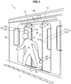
- FIG. 1 is an explanatory view showing a doorway 10 of a train vehicle 1 with pinch detection sensors 2 according to a first embodiment of the present invention being attached to left and right sliding doors 11 and 11, respectively, of the doorway 10.
- a passenger 8 exiting from the train vehicle 1 to a station platform 7 and belongings 9 of the passenger 8.
- entry and exit directions of the passenger 8 are indicated by arrows A 1
- moving directions (closing directions) during closing of the sliding doors 11 and 11 are indicated by arrows A 2 .
- the moving directions of the sliding doors 11 and 11 are parallel to a forward movement direction of the train vehicle 1.
- the entry and exit directions of the passenger 8 are perpendicular to the forward movement direction of the train vehicle 1 and parallel to thickness directions of the sliding doors 11 and 11.
- Each sliding door 11 includes a door plate 111 and a window glass 112 fitted in a window section 111 a of the door plate 111.
- the sliding doors 11 and 11 are slid in front and rear directions of the vehicle body 12 to open and close the doorway 10.
- the driving devices 13 and 13 are disposed above the doorway 10, and are configured to include a linear motion mechanism such as a linear motor and a ball screw, for example. Further, the driving devices 13 and 13 are controlled by a control device 14.
- the movement ranges (the positions of forward and backward movement ends) of the sliding doors 11 and 11 are defined by stoppers (not shown) which are provided in the driving devices 13 and 13.
- the pinch detection sensors 2 are vertically attached to respective edge portions of the left and right sliding doors 11 and 11 opposite each other, and during closing of the sliding doors 11 and 11, in the event of pinch of the passenger 8 or their belongings 9 therebetween, the pinch detection sensors 2 detect that occurrence of pinch.
- the control device 14 controls the driving devices 13 and 13 for opening the sliding doors 11 and 11.
- the control device 14 may generate an alarm signal to give an alarm to a trainman such as a driver or a conductor. In this case, the sliding doors 11 and 11 are opened by being operated by the trainman.
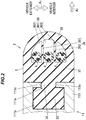
- FIG. 2 is a cross-sectional view showing the pinch detection sensor 2 in a natural condition when not subjected to occurrence of pinch.
- the pinch detection sensor 2 is indicated by a cross section parallel to the entry and exit directions A 1 of the passenger 8 and the closing directions A 2 of the sliding doors 11 and 11 (in other words, a cross section at right angles to a longitudinal direction of the pinch detection sensor 2 ).
- the upper side of the drawing corresponds to the vehicle exterior side (platform 7 side) of the train vehicle 1
- the lower side of the drawing corresponds to the vehicle interior side.
- the pinch detection sensor 2 includes a door front edge rubber 3, which is attached to a front edge portion of the sliding door 11 in the closing direction of the sliding door 11, and a plurality of linear shape pressure sensing members 4.
- the door front edge rubber 3 has a hollow portion 30 inside, and the plurality of linear shape pressure sensing members 4 are being accommodated in the hollow portion 30. In the present embodiment, three of the linear shape pressure sensing members 4 are accommodated in the hollow portion 30.
- the door plate 111 is vertically formed with a mating groove 111 b for attaching the door front edge rubber 3.
- the mating groove 111 b is open in the closing direction of the sliding door 11 through an opening 111 d between one pair of protruding pieces 111c and 111c opposite each other.
- the door front edge rubber 3 integrally includes, in the cross section shown in FIG. 2 , a rectangular base section 31, a cover section 32, which covers the three linear shape pressure sensing members 4 in the closing direction of the sliding door 11 relative to the hollow portion 30, a mating portion 33, which is mated into the mating groove 111 b of the door plate 111, and a connecting portion 34, which connects the base section 31 and the mating portion 33.
- the door front edge rubber 3 is made of, for example, urethane rubber, EP rubber, silicone rubber, styrene butadiene rubber, chloroprene rubber, olefin based or styrene based thermoplastic elastomer, urethane resin or the like, and is formed by extrusion molding.
- the base section 31 is disposed on the one pair of protruding pieces 111 c and 111 c of the door plate 111 in the closing direction of the sliding door 11, and forms the hollow portion 30 between that base section 31 and the cover section 32.
- the cover section 32 is curved in an arch shape (a semicircular shape) protruding in the closing direction of the sliding door 11 in a middle portion in the passenger entry and exit directions, and is continuous with the base section 31 at both end portions of the cover section 32.
- the connecting portion 34 is disposed in the opening 111 d of the door plate 111.
- the door front edge rubber 3 includes a partitioning portion 35 between the base section 31 and the cover section 32, which partitions the hollow portion 30 into a plurality (three in the present embodiment) of housing spaces 301 to 303.
- the three housing spaces 301 to 303 will be referred to as the first to third housing spaces 301, 302, and 303, respectively.
- the first to third housing spaces 301, 302, and 303 are being aligned in the passenger entry and exit directions, in such a manner that the first housing space 301 is being formed in the middle portion in the passenger entry and exit directions, the second housing space 302 is being formed on the vehicle exterior side relative to the first housing space 301, and the third housing space 303 is being formed on the vehicle interior side relative to the first housing space 301.
- the partitioning portion 35 includes a first wall section 351 that partitions the first housing space 301 and the second housing space 302, and a second wall section 352 that partitions the first housing space 301 and the third housing space 303.
- the first wall section 351 and the second wall section 352 are being provided parallel to each other in the moving direction of the sliding door 11. Further, the first wall section 351 and the second wall section 352 are continuous with the base section 31 at their respective one end portions, while being continuous with the cover section 32 at their respective other end portions. This results in the first to third housing spaces 301, 302, and 303 being partitioned with no gap therebetween by the partitioning portion 35.
- the three linear shape pressure sensing members 4 are being accommodated in the first to third housing spaces 301, 302, and 303, respectively.
- the door front edge rubber 3 includes, in the hollow portion 30, the first to third housing spaces 301, 302, and 303 for accommodating the plurality of linear shape pressure sensing members 4 respectively, so that movements of the linear shape pressure sensing members 4 between the first to third housing spaces 301, 302, and 303 are restricted by the partitioning portion 35.
- the area of the hollow space excluding the portion where the linear shape pressure sensing member 4 is disposed is greater than the area of the portion where the linear shape pressure sensing member 4 is disposed. That is, when the proportion of the hollow space in the first housing space 301 is defined as the space ratio, this space ratio is 50% or more. This results in impact relaxation when the door front edge rubber 3 collides with the passenger 8 body during closing of the sliding doors 11 and 11.
- the space ratios of the second and third housing spaces 302 and 303 are also 50% or more. It should be noted, however, that the space ratios of the second and third housing spaces 302 and 303 are lower than the space ratio of the first housing space.
- the desirable range of the space ratio of the first housing space is 50% or more and 80% or less, while the desirable ranges of the space ratios of the second and third housing spaces 302 and 303 are 40% or more and 70% or less. This is because if the space ratios are too low, the cushionability lowers, or if the space ratios are too high, the locations of the linear shape pressure sensing members 4 may be not fixed in appropriate ranges.
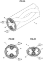
- FIG. 3 A is a perspective view showing the linear shape pressure sensing member 4.
- FIG. 3 B is a cross-sectional view of the linear shape pressure sensing member 4 in a natural condition when acted on by no external force.
- FIG. 3 C is a cross-sectional view of the linear shape pressure sensing member 4 in a compressed condition when acted on by an external force.
- the linear shape pressure sensing member 4 includes a tube 41 which is formed of a tubular elastic body, and a plurality of conductor wires 42 which are spaced apart from each other in an inner side of that tube 41. More specifically, two conductor wires 42 are being helically held on an inner surface of the tube 41 while being partially exposed, with a space 40 being formed in a central portion of the tube 41.
- the tube 41 is made of, e.g., an insulating rubber material such as silicone rubber or ethylene propylene rubber, and has such elasticity as to be deformed by being acted on by an external force, and restored immediately no external force is exerted.
- the plurality of conductor wires 42 are being held in non-contact with each other with the space 40 therebetween. Further, the tube 41 when acted on by an external force is elastically deformed to bring the plurality of conductor wires 42 into contact with each other.
- a metal stranded wire 421 with multiple metal wires stranded together is being covered with a conductive covering layer 422. This structure allows the linear shape pressure sensing member 4 to sense external pressure forces in all radial directions of the tube 41.
- the electric circuit 5 is shown for only one linear shape pressure sensing member 4, since in the present embodiment, the pinch detection sensor 2 has the three linear shape pressure sensing members 4, each of the linear shape pressure sensing members 4 is being provided with its each electric circuit 5, and the detection signals of the ammeters 53 of their respective electric circuits 5 are output to the control device 14.
- the control device 14 when recognizing the occurrence of compression of any of the linear shape pressure sensing members 4 stops or reverses the driving device 13.
- the plurality of linear shape pressure sensing members 4 are being arranged at locations different from each other in the passenger entry and exit directions. That is, the plurality of linear shape pressure sensing members 4 are being arranged in such a manner as to be aligned in a direction which intersects the moving directions of the sliding doors 11 and 11 and the longitudinal direction (vertical direction) of the door front edge rubber 3, and be not overlapped in the moving directions of the sliding doors 11 and 11.
- the direction which intersects the moving directions of the sliding doors 11 and 11 and the longitudinal direction of the door front edge rubber 3 is referred to as the alignment direction.
- one linear shape pressure sensing member 4 accommodated in the first housing space 301 is disposed in the middle portion in the alignment direction in the hollow portion 30, while the other two linear shape pressure sensing members 4 are disposed on one side (vehicle exterior side) and the other side (vehicle interior side), respectively, in the alignment direction of the one linear shape pressure sensing member 4 accommodated in the first housing space 301.
- the linear shape pressure sensing member 4 disposed on one side is being accommodated in the second housing space 302, while the linear shape pressure sensing member 4 disposed on the other side is being accommodated in the third housing space 303.
- the lengths of the first to third housing spaces 301 to 303 in a width direction of the sliding door 11 in the movement direction of the sliding door 11 are greater than the diameters of the linear shape pressure sensing members 4, thereby allowing the linear shape pressure sensing member 4 accommodated in the first housing space 301 to be moved in the width direction of the sliding door 11 within the first housing space 301, the linear shape pressure sensing member 4 accommodated in the second housing space 302 to be moved in the width direction of the sliding door 11 within the second housing space 302, and the linear shape pressure sensing member 4 accommodated in the third housing space 303 to be moved in the width direction of the sliding door 11 within the third housing space 303.
- the first housing space 301 located in the middle portion in the alignment direction is longer in length in the width direction of the sliding door 11 than the second and third housing spaces 302 and 303, so that the impact when the tip of the cover section 32 collides with the passenger 8 is greatly relaxed.
- the length of the first housing space 301 in the width direction of the sliding door 11 is twice or more the diameter of the linear shape pressure sensing members 4.
- FIG. 6 shows the train vehicle 1 departing in its forward movement direction indicated by arrow A 3 with the string-like object 92 of the belongings 9 of the passenger 8 having exited to the vehicle exterior remaining pinched between the left and right sliding doors 11 and 11 of that vehicle 1, with the main body object 91 of their belongings 9 being left behind in the vehicle interior.
- the linear shape pressure sensing member 4 accommodated in the second housing space 302 of the pinch detection sensor 2 attached to the rear sliding door 11 in the vehicle forward movement direction of the left and right sliding doors 11 is compressed, with its two conductor wires 42 being brought into contact with each other.
- the cover section 32 of the door front edge rubber 3 may be pulled to the vehicle exterior side, to compress the linear shape pressure sensing member 4 accommodated in the third housing space 303, and bring its two conductor wires 42 into contact with each other.
- the linear shape pressure sensing member 4 accommodated in the third housing space 303 can also be compressed when the passenger 8 collides with the door front edge rubber 3 by exiting from the vehicle interior side to the vehicle exterior side during closing of the sliding doors 11 and 11.
- the linear shape pressure sensing member 4 accommodated in the second housing space 302 can also be compressed when the passenger 8 collides with the door front edge rubber 3 by entering the vehicle interior side from the vehicle exterior side during closing of the sliding doors 11 and 11.
- the train vehicle 1 When the occurrence of pinch is detected with the pinch detection sensors 2 after departure of the train vehicle 1, the train vehicle 1 is promptly stopped by the manual operation of the driver having received the alarm, or automatically in the case of automatic running, to open the sliding doors 11 and 11.
- FIG. 7 is a cross-sectional view showing a pinch detection sensor 2 A according to the second embodiment.
- the base section 31 of the door front edge rubber 3 has a semicircular protrusion 311 which protrudes in a door closing direction (to the cover section 32 side) in the middle portion in the alignment direction.
- This protrusion 311 is being formed across the first to third housing spaces 301 to 303, and is most protruding toward the first housing space 301.
- the pinch detection sensor 2 A since the length of the first housing space 301 is shorter than that of the first embodiment, even when the amount of deformation of the cover section 32 is small, the two conductor wires 42 of the linear shape pressure sensing member 4 accommodated in the first housing space 301 are brought into contact with each other, so even when the external force is relatively small, it is possible to detect the occurrence of pinch.
- FIG. 8 is a cross-sectional view showing a pinch detection sensors 2 B according to a third embodiment.
- the detection switch 2 B is being provided with a protrusion 311 in the base section 31 which protrudes in the door closing direction in the middle portion in the alignment direction, but unlike that of the second embodiment, that protrusion 311 in the third embodiment is being formed into a trapezoidal shape.
- the protrusion 311 becomes wider in width in the alignment direction with increasing distance from the top surface of the first housing space 301, so the distance between both side surfaces of the second and third housing spaces 302 and 303 becomes longer.
- the first wall section 351 and the second wall section 352 are extending from the corners between the top surface and both the side surfaces of the protrusion 311, and at such oblique angles as to be separated from each other with respect to the moving direction of the sliding door 11.
- FIG. 9 is a cross-sectional view showing a pinch detection sensor 2 C according to a fourth embodiment.
- the hollow portion 30 of the door front edge rubber 3 is partitioned into three housing spaces
- the hollow portion 30 in the pinch detection sensor 2 C according to the present embodiment is partitioned into two housing spaces. More specifically, the hollow portion 30 is partitioned into a first housing space 304 and a second housing space 305 by a single wall-like partitioning portion 353, and respective one linear shape pressure sensing members 4 are being accommodated in the first housing space 304 and the second housing space 305.
- FIG. 10 is a cross-sectional view showing a pinch detection sensor 2D according to the fifth embodiment.
- the first to third housing spaces 301 to 303 are partitioned with no gap therebetween by the partitioning portion 35
- the first to third housing spaces 301 to 303 in the pinch detection sensor 2 D according to the present embodiment are being configured in communication via gaps S 1 and S 2 .
- the sizes of the gaps S 1 and S 2 are narrower than the diameters of the linear shape pressure sensing members 4, so the movements of the linear shape pressure sensing members 4 between the first to third housing spaces 301 to 303 are restricted by the partition part 35 in the same manner as in each of the above embodiments.
- FIG. 11 is a cross-sectional view showing a pinch detection sensor 2 E according to the sixth embodiment of the present invention.
- This pinch detection sensor 2 E is provided with a protrusion 311 in the base section 31 of the door front edge rubber 3 of the pinch detection sensor 2 D according to the fifth embodiment, in the same manner as in the second embodiment.
- FIG. 12 is a cross-sectional view showing a pinch detection sensor 2 F according to the seventh embodiment.
- the pinch detection sensor 2 F is being provided with a protrusion 311 in the base section 31 of the door front edge rubber 3, and a partitioning portion 35 is being provided on a tip of that protrusion 311.
- the partitioning portion 35 is being formed with an arc-shaped surface opposite the cover section 32, which is greater in curvature than the outer circumferential surfaces of the linear shape pressure sensing members 4, and includes first and second protruding corner sections 354 and 355 in both end portions in the alignment direction.
- Gaps S 3 and S 4 are being formed between the first and second protruding corner sections 354 and 355, respectively, and the cover section 32.
- the sizes of the gaps S 3 and S 4 are narrower than the diameters of the linear shape pressure sensing members 4, so the movements of the linear shape pressure sensing members 4 between the first to third housing spaces 301 to 303 are restricted.
- the seventh embodiment it is possible to detect with the protrusion 311 the occurrence of pinch which causes a relatively small external force, and since the first to third housing spaces 301 to 303 are being configured in communication with each other via the gaps S 3 and S 4 , the production of the door front edge rubber 3 is facilitated.
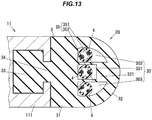
- FIG. 13 is a cross-sectional view showing a pinch detection sensor 2 G according to the eighth embodiment.
- the cover section 32 of the door front edge rubber 3 has an inward protrusion 321 which protrudes toward the base section 31 and to the one linear shape pressure sensing member 4 accommodated in the first housing space 301.
- the first wall section 351 that partitions the first housing space 301 and the second housing space 302, and the second wall section 352 that partitions the first housing space 301 and the third housing space 303 are being provided between the base section 31 and the inward protrusion 321 of the cover section 32.
- the two conductor wires 42 of the linear shape pressure sensing member 4 accommodated in the first housing space 301 are brought into contact with each other, so even when the external force is relatively small, it is possible to detect the occurrence of pinch in the closing direction of the sliding door 11.
- FIG. 14 a ninth embodiment of the present invention will be described with reference to FIG. 14 .
- the pinch detection sensor attached to one of the left and right sliding doors 11 and 11 and the pinch detection sensor attached to the other sliding door 11 in the present embodiment are different in structure.
- the pinch detection sensor attached to one sliding door 11 will be referred to as one pinch detection sensor 2 H
- the pinch detection sensor attached to the other sliding door 11 will be referred to as the other pinch detection sensor 2 I .
- the one pinch detection sensor 2 H is further provided with an outward protrusion 322 in the cover section 32 of the pinch detection sensor 2 G according to the eighth embodiment.
- the outward protrusion 232 is protruding from the middle portion in the alignment direction of the cover sections 32 toward the other pinch detection sensor 2 I and to the opposite side to the hollow portion 30.
- the other pinch detection sensor 2 I is configured as a modification to the pinch detection sensor 2 C according to the fourth embodiment, and is being provided with a mating recessed portion 300 in the middle portion in the alignment direction of the cover section 32, which is mated with the outward protrusion 322 of the one pinch detection sensor 2 H.
- the mating recessed portion 300 is being formed in a range from the cover section 32 to the partitioning portion 353. Note that in the door front edge rubber 3 of the other pinch detection sensor 2 I, the thickness in the alignment direction of the partitioning portion 353 that partitions the hollow portion 30 into the first housing space 304 and the second housing space 305 is being formed thicker at least in the end portion in the closing direction than the width in the alignment direction of the mating recessed portion 300.
- the pressure due to that pinch is easily transmitted from the outward protrusion 322 of the one pinch detection sensor 2 H to the linear shape pressure sensing member 4 accommodated in the first housing space 301, so it is possible to securely detect the occurrence of that pinch.
- the outward protrusion 322 of the one pinch detection sensor 2 H being mated to the mating recessed portion 300 of the other pinch detection sensor 2 I, the airtightness of the interior of the train vehicle 1 is enhanced and besides, the occurrence of rattling of the sliding doors 11 and 11 is suppressed.
- the present invention can appropriately be modified and implemented without departing from the spirit thereof.
- the present invention is not limited thereto, but may also be applied to, for example so-called home door sliding doors which are provided on the platform 7 and which are opened after arrival of the train vehicle 1 and closed before departure of the train vehicle 1.
Landscapes
- Engineering & Computer Science (AREA)
- Mechanical Engineering (AREA)
- Computer Security & Cryptography (AREA)
- Civil Engineering (AREA)
- Structural Engineering (AREA)
- Power-Operated Mechanisms For Wings (AREA)
- Push-Button Switches (AREA)
- Specific Sealing Or Ventilating Devices For Doors And Windows (AREA)
- Platform Screen Doors And Railroad Systems (AREA)
Abstract
Description
- The present application is based on Japanese patent application No.
2018-120052 filed on June 25, 2018 - The present invention relates to a pinch detection sensor for detecting the occurrence of pinch during closing of a sliding door.
- Conventionally, in a train vehicle doorway to allow passenger entry and exit, there are provided sliding doors that slide in train vehicle front and rear directions. Such train vehicle sliding doors are provided with a structure for detecting the occurrence of passenger's body or belongings pinch in the sliding doors during closing of the sliding doors (see, e.g.,
JP-A-2017-89247 - The door pinch detecting device described in
JP-A-2017-89247 - On the other hand, the present applicant has suggested a cord switch (i.e. cord-shape switch type detection sensor) for detecting the occurrence of pinch in an automobile sliding door as described in e.g.
JP-A-2014-216300 - [Patent Document 1]
JP-A-2017-89247 - [Patent Document 2]
JP-A-2014-216300 - Although the door pinch detecting device described in
JP-A-2017-89247 - Even in the event of such pinch, in order to be able to detect the occurrence of pinch, the present inventors have considered, in the cord switch described in
JP-A-2014-216300 - Accordingly, it is an object of the present invention to provide a pinch detection sensor, which, during closing of a sliding door, is able to detect the occurrence of pinch, even when acted on by an external force at oblique angles to a moving direction of the sliding door.
- For the purpose of solving the above-described problem, the present invention provides a pinch detection sensor, for detecting the occurrence of pinch during closing of a sliding door, comprising: a door front edge rubber including a hollow portion inside, to be attached to a front edge portion of the sliding door in a closing movement direction of the sliding door; and a plurality of linear shape pressure sensing members accommodated in the hollow portion, each linear shape pressure sensing member comprising a tubular elastic body and respective conductor wires spaced apart from each other in an inner side of the tubular elastic body; wherein the door front edge rubber includes, in the hollow portion, a plurality of housing spaces, which accommodate the plurality of linear shape pressure sensing members, respectively, wherein movements of the linear shape pressure sensing members between the plurality of housing spaces are restricted by a partitioning portion.
- The pinch detection sensor according to the present invention makes it possible to, during closing of the sliding door, detect the occurrence of pinch, even when acted on by an external force at oblique angles to the moving direction of the sliding door.
-
-
FIG. 1 is an explanatory view showing a train vehicle doorway with a pinch detection sensor according to a first embodiment of the present invention attached to left and right sliding doors thereof; -
FIG. 2 is a cross-sectional view showing the pinch detection sensor; -
FIG. 3A is a perspective view showing a linear shape pressure sensing member; -
FIG. 3B is a cross-sectional view of the linear shape pressure sensing member in a natural condition when acted on by no external force; -
FIG. 3C is a cross-sectional view of the linear shape pressure sensing member in a compressed condition when acted on by an external force; -
FIG. 4 is a circuit diagram showing one example of an electric circuit for detecting the occurrence of pinch in the sliding doors with the linear shape pressure sensing member; -
FIG. 5 is an explanatory view showing a tip in a door closing direction of a cover section of a door front edge rubber when colliding with a part of a passenger's body; -
FIG. 6 is an explanatory view showing a train vehicle departing with a string-like object of belongings of a passenger having exited to the vehicle exterior remaining pinched between the left and right sliding doors of that vehicle, with a main body object of their belongings being left behind in the vehicle interior; -
FIG. 7 is a cross-sectional view showing a pinch detection sensor according to a second embodiment; -
FIG. 8 is a cross-sectional view showing a pinch detection sensor according to a third embodiment; -
FIG. 9 is a cross-sectional view showing a pinch detection sensor according to a fourth embodiment; -
FIG. 10 is a cross-sectional view showing a pinch detection sensor according to a fifth embodiment; -
FIG. 11 is a cross sectional view showing a pinch detection sensor according to a sixth embodiment; -
FIG. 12 is a cross-sectional view showing a pinch detection sensor according to a seventh embodiment; -
FIG. 13 is a cross-sectional view showing a pinch detection sensor according to an eighth embodiment; and -
FIG. 14 is a cross-sectional view showing a pinch detection sensor according to a ninth embodiment. -
FIG. 1 is an explanatory view showing adoorway 10 of atrain vehicle 1 withpinch detection sensors 2 according to a first embodiment of the present invention being attached to left and right slidingdoors doorway 10. InFIG. 1 , there are shown apassenger 8 exiting from thetrain vehicle 1 to astation platform 7 andbelongings 9 of thepassenger 8. Further, inFIG. 1 , entry and exit directions of thepassenger 8 are indicated by arrows A 1 , while moving directions (closing directions) during closing of the slidingdoors - The moving directions of the sliding
doors train vehicle 1. The entry and exit directions of thepassenger 8 are perpendicular to the forward movement direction of thetrain vehicle 1 and parallel to thickness directions of the slidingdoors door 11 includes adoor plate 111 and awindow glass 112 fitted in awindow section 111a of thedoor plate 111. - The
belongings 9 include, for example, amain body object 91 such as a pass holder for holding cards, and a string-like object 92 which is coupled to themain body object 91 at one end thereof. The other end of the string-like object 92 is gripped by thepassenger 8. Note that the other end of the string-like object 92 may be suspended by a belt or the like of thepassenger 8, for example. - By
driving devices vehicle body 12, the slidingdoors vehicle body 12 to open and close thedoorway 10. Thedriving devices doorway 10, and are configured to include a linear motion mechanism such as a linear motor and a ball screw, for example. Further, thedriving devices control device 14. The movement ranges (the positions of forward and backward movement ends) of the slidingdoors driving devices - The
pinch detection sensors 2 are vertically attached to respective edge portions of the left and right slidingdoors doors passenger 8 or theirbelongings 9 therebetween, thepinch detection sensors 2 detect that occurrence of pinch. When thecontrol device 14 receives a signal indicating that occurrence of pinch from thepinch detection sensors 2, thecontrol device 14 controls thedriving devices doors control device 14 receives a signal indicating the occurrence of pinch from thepinch detection sensors 2, thecontrol device 14 may generate an alarm signal to give an alarm to a trainman such as a driver or a conductor. In this case, the slidingdoors -
FIG. 2 is a cross-sectional view showing thepinch detection sensor 2 in a natural condition when not subjected to occurrence of pinch. InFIG. 2 , thepinch detection sensor 2 is indicated by a cross section parallel to the entry and exit directions A 1 of thepassenger 8 and the closing directions A 2 of the slidingdoors 11 and 11 (in other words, a cross section at right angles to a longitudinal direction of the pinch detection sensor 2). Further, inFIG. 2 , the upper side of the drawing corresponds to the vehicle exterior side (platform 7 side) of thetrain vehicle 1, while the lower side of the drawing corresponds to the vehicle interior side. - The
pinch detection sensor 2 includes a doorfront edge rubber 3, which is attached to a front edge portion of the slidingdoor 11 in the closing direction of the slidingdoor 11, and a plurality of linear shapepressure sensing members 4. The doorfront edge rubber 3 has ahollow portion 30 inside, and the plurality of linear shapepressure sensing members 4 are being accommodated in thehollow portion 30. In the present embodiment, three of the linear shapepressure sensing members 4 are accommodated in thehollow portion 30. - The
door plate 111 is vertically formed with amating groove 111b for attaching the doorfront edge rubber 3. Themating groove 111b is open in the closing direction of the slidingdoor 11 through anopening 111d between one pair of protrudingpieces - The door
front edge rubber 3 integrally includes, in the cross section shown inFIG. 2 , arectangular base section 31, acover section 32, which covers the three linear shapepressure sensing members 4 in the closing direction of the slidingdoor 11 relative to thehollow portion 30, amating portion 33, which is mated into themating groove 111b of thedoor plate 111, and a connectingportion 34, which connects thebase section 31 and themating portion 33. The doorfront edge rubber 3 is made of, for example, urethane rubber, EP rubber, silicone rubber, styrene butadiene rubber, chloroprene rubber, olefin based or styrene based thermoplastic elastomer, urethane resin or the like, and is formed by extrusion molding. - The
base section 31 is disposed on the one pair of protrudingpieces door plate 111 in the closing direction of the slidingdoor 11, and forms thehollow portion 30 between thatbase section 31 and thecover section 32. Thecover section 32 is curved in an arch shape (a semicircular shape) protruding in the closing direction of the slidingdoor 11 in a middle portion in the passenger entry and exit directions, and is continuous with thebase section 31 at both end portions of thecover section 32. The connectingportion 34 is disposed in theopening 111d of thedoor plate 111. - Further, the door
front edge rubber 3 includes apartitioning portion 35 between thebase section 31 and thecover section 32, which partitions thehollow portion 30 into a plurality (three in the present embodiment) ofhousing spaces 301 to 303. Hereinafter, the threehousing spaces 301 to 303 will be referred to as the first tothird housing spaces third housing spaces first housing space 301 is being formed in the middle portion in the passenger entry and exit directions, thesecond housing space 302 is being formed on the vehicle exterior side relative to thefirst housing space 301, and thethird housing space 303 is being formed on the vehicle interior side relative to thefirst housing space 301. - The partitioning
portion 35 includes afirst wall section 351 that partitions thefirst housing space 301 and thesecond housing space 302, and asecond wall section 352 that partitions thefirst housing space 301 and thethird housing space 303. Thefirst wall section 351 and thesecond wall section 352 are being provided parallel to each other in the moving direction of the slidingdoor 11. Further, thefirst wall section 351 and thesecond wall section 352 are continuous with thebase section 31 at their respective one end portions, while being continuous with thecover section 32 at their respective other end portions. This results in the first tothird housing spaces portion 35. The three linear shapepressure sensing members 4 are being accommodated in the first tothird housing spaces - In this manner, in the present embodiment, the door
front edge rubber 3 includes, in thehollow portion 30, the first tothird housing spaces pressure sensing members 4 respectively, so that movements of the linear shapepressure sensing members 4 between the first tothird housing spaces portion 35. - Of the area occupied by the
first housing space 301 in the cross section shown inFIG. 2 , the area of the hollow space excluding the portion where the linear shapepressure sensing member 4 is disposed is greater than the area of the portion where the linear shapepressure sensing member 4 is disposed. That is, when the proportion of the hollow space in thefirst housing space 301 is defined as the space ratio, this space ratio is 50% or more. This results in impact relaxation when the doorfront edge rubber 3 collides with thepassenger 8 body during closing of the slidingdoors - In the present embodiment, the space ratios of the second and
third housing spaces third housing spaces third housing spaces pressure sensing members 4 may be not fixed in appropriate ranges. -
FIG. 3A is a perspective view showing the linear shapepressure sensing member 4.FIG. 3B is a cross-sectional view of the linear shapepressure sensing member 4 in a natural condition when acted on by no external force.FIG. 3C is a cross-sectional view of the linear shapepressure sensing member 4 in a compressed condition when acted on by an external force. - The linear shape
pressure sensing member 4 includes atube 41 which is formed of a tubular elastic body, and a plurality ofconductor wires 42 which are spaced apart from each other in an inner side of thattube 41. More specifically, twoconductor wires 42 are being helically held on an inner surface of thetube 41 while being partially exposed, with aspace 40 being formed in a central portion of thetube 41. Thetube 41 is made of, e.g., an insulating rubber material such as silicone rubber or ethylene propylene rubber, and has such elasticity as to be deformed by being acted on by an external force, and restored immediately no external force is exerted. - In a natural condition of the
tube 41 when acted on by no external force, the plurality ofconductor wires 42 are being held in non-contact with each other with thespace 40 therebetween. Further, thetube 41 when acted on by an external force is elastically deformed to bring the plurality ofconductor wires 42 into contact with each other. In each of theconductor wires 42, a metal strandedwire 421 with multiple metal wires stranded together is being covered with aconductive covering layer 422. This structure allows the linear shapepressure sensing member 4 to sense external pressure forces in all radial directions of thetube 41. -
FIG. 4 is a circuit diagram showing one example of anelectric circuit 5 for detecting the occurrence of pinch in the slidingdoor 11 with the linear shapepressure sensing member 4. Theelectric circuit 5 is being configured to include the twoconductor wires 42 of the linear shapepressure sensing member 4, and includes apower source 51, acontact detection resistor 52 that connects together end portions of the twoconductor wires 42, anammeter 53 and acurrent limitation resistor 54 that are connected in series with thepower supply 51. Theammeter 53 includes, for example, a current sensor such as a Hall IC and an amplifier, and its detection signal is output to thecontrol device 14. - In the
electric circuit 5 configured as described above, when the linear shapepressure sensing member 4 is compressed and theconductor wires 42 are brought into contact with each other, electric current to be detected by theammeter 53 varies. Thecontrol device 14 recognizes the occurrence of pinch in the slidingdoor 11 from the variation of the detection signal of theammeter 53, and stops or reverses the drivingdevice 13. - Note that although in
FIG. 4 theelectric circuit 5 is shown for only one linear shapepressure sensing member 4, since in the present embodiment, thepinch detection sensor 2 has the three linear shapepressure sensing members 4, each of the linear shapepressure sensing members 4 is being provided with its eachelectric circuit 5, and the detection signals of theammeters 53 of their respectiveelectric circuits 5 are output to thecontrol device 14. Thecontrol device 14 when recognizing the occurrence of compression of any of the linear shapepressure sensing members 4 stops or reverses the drivingdevice 13. - In the present embodiment, in order to enable secure detection of occurrence of pinch even when acted on by an external force at oblique angles to the moving direction of the sliding
door 11 during closing of the slidingdoor 11, the plurality of linear shapepressure sensing members 4 are being arranged at locations different from each other in the passenger entry and exit directions. That is, the plurality of linear shapepressure sensing members 4 are being arranged in such a manner as to be aligned in a direction which intersects the moving directions of the slidingdoors front edge rubber 3, and be not overlapped in the moving directions of the slidingdoors doors front edge rubber 3 is referred to as the alignment direction. - More specifically, of the three linear shape
pressure sensing members 4, one linear shapepressure sensing member 4 accommodated in thefirst housing space 301 is disposed in the middle portion in the alignment direction in thehollow portion 30, while the other two linear shapepressure sensing members 4 are disposed on one side (vehicle exterior side) and the other side (vehicle interior side), respectively, in the alignment direction of the one linear shapepressure sensing member 4 accommodated in thefirst housing space 301. The linear shapepressure sensing member 4 disposed on one side is being accommodated in thesecond housing space 302, while the linear shapepressure sensing member 4 disposed on the other side is being accommodated in thethird housing space 303. - The lengths of the first to
third housing spaces 301 to 303 in a width direction of the slidingdoor 11 in the movement direction of the slidingdoor 11 are greater than the diameters of the linear shapepressure sensing members 4, thereby allowing the linear shapepressure sensing member 4 accommodated in thefirst housing space 301 to be moved in the width direction of the slidingdoor 11 within thefirst housing space 301, the linear shapepressure sensing member 4 accommodated in thesecond housing space 302 to be moved in the width direction of the slidingdoor 11 within thesecond housing space 302, and the linear shapepressure sensing member 4 accommodated in thethird housing space 303 to be moved in the width direction of the slidingdoor 11 within thethird housing space 303. - With this door
front edge rubber 3 structure, even when a part of thepassenger 8 body is pinched between the slidingdoors doors passenger 8 is mitigated by the cushionability of the doorfront edge rubber 3 enhanced by the spaces of the first tothird housing spaces 301 to 303. In particular, thefirst housing space 301 located in the middle portion in the alignment direction is longer in length in the width direction of the slidingdoor 11 than the second andthird housing spaces cover section 32 collides with thepassenger 8 is greatly relaxed. In the present embodiment, the length of thefirst housing space 301 in the width direction of the slidingdoor 11 is twice or more the diameter of the linear shapepressure sensing members 4. -
FIG. 5 shows the compressed linear shapepressure sensing member 4 accommodated in thefirst housing space 301 when the tip of thecover section 32 of the doorfront edge rubber 3 in the closing direction of the slidingdoor 11 collides with apart 81 of thepassenger 8 body during closing of the slidingdoor 11. The linear shapepressure sensing member 4 accommodated in thefirst housing space 301 is being sandwiched between thecover section 32 and thebase section 31, with thetube 41 being elastically deformed, with the twoconductor wires 42 being brought into contact with each other. -
FIG. 6 shows thetrain vehicle 1 departing in its forward movement direction indicated by arrow A 3 with the string-like object 92 of thebelongings 9 of thepassenger 8 having exited to the vehicle exterior remaining pinched between the left and right slidingdoors vehicle 1, with themain body object 91 of theirbelongings 9 being left behind in the vehicle interior. - In this condition, the linear shape
pressure sensing member 4 accommodated in thesecond housing space 302 of thepinch detection sensor 2 attached to therear sliding door 11 in the vehicle forward movement direction of the left and right slidingdoors 11 is compressed, with its twoconductor wires 42 being brought into contact with each other. This results in detection of the occurrence of pinch. That is, with thepinch detection sensors 2 according to the present embodiment, even when the string-like object 92 has such a thickness dimension that the occurrence of pinch is not detected only by it being pinched between the left and right slidingdoors pressure sensing member 4 being acted on by the external force at the oblique angle to the closing direction of the slidingdoor 11 as shown inFIG. 6 . - Note that although not shown, when the
train vehicle 1 departs with the string-like object 92 remaining pinched between the left and right slidingdoors cover section 32 of the doorfront edge rubber 3 may be pulled to the vehicle exterior side, to compress the linear shapepressure sensing member 4 accommodated in thethird housing space 303, and bring its twoconductor wires 42 into contact with each other. Further, the linear shapepressure sensing member 4 accommodated in thethird housing space 303 can also be compressed when thepassenger 8 collides with the doorfront edge rubber 3 by exiting from the vehicle interior side to the vehicle exterior side during closing of the slidingdoors pressure sensing member 4 accommodated in thesecond housing space 302 can also be compressed when thepassenger 8 collides with the doorfront edge rubber 3 by entering the vehicle interior side from the vehicle exterior side during closing of the slidingdoors - When the occurrence of pinch is detected with the
pinch detection sensors 2 after departure of thetrain vehicle 1, thetrain vehicle 1 is promptly stopped by the manual operation of the driver having received the alarm, or automatically in the case of automatic running, to open the slidingdoors - According to the first embodiment described above, the following operations and advantageous effects (1) to (3) can be obtained.
- (1) Since the
hollow portion 30 is partitioned by the partitioningportion 35 into the first tothird housing spaces 301 to 303, the movements of the plurality of linear shapepressure sensing members 4 within thehollow portion 30 of the doorfront edge rubber 3 are restricted, to be able to fix the plurality of linear shapepressure sensing members 4 at such locations, respectively, that the plurality of linear shapepressure sensing members 4 are acted on by external forces in various directions. This makes it possible to detect the occurrence of pinch, even when the plurality of linear shapepressure sensing members 4 are acted on by external forces at oblique angles to the movement direction of the slidingdoor 11 during closing of the slidingdoor 11. - (2) Since the plurality of linear shape
pressure sensing members 4 are not overlapped in the moving direction of the slidingdoor 11 and are being arranged at locations different from each other in the alignment direction, the angle range in which the pressure can be detected by thepinch detection sensors 2 is wide. Further, in the present embodiment, since the occurrence of pinch in the closing direction of the slidingdoor 11 which occurs with high frequency is detected by one linear shapepressure sensing member 4 disposed in the middle portion in the alignment direction, while the occurrence of pinch at oblique angles to the closing directions of the slidingdoors 11 is detected by the other two linear shapepressure sensing members 4, it is possible to securely detect various types of occurrence of pinch. - (3) Since the first to
third housing spaces portion 35, the plurality of linear shapepressure sensing members 4 can appropriately be disposed without being moved between the first tothird housing spaces front edge rubber 3 is deformed. - Next, a second embodiment of the present invention will be described with reference to
FIG. 7. FIG. 7 is a cross-sectional view showing apinch detection sensor 2A according to the second embodiment. In the present embodiment, thebase section 31 of the doorfront edge rubber 3 has asemicircular protrusion 311 which protrudes in a door closing direction (to thecover section 32 side) in the middle portion in the alignment direction. Thisprotrusion 311 is being formed across the first tothird housing spaces 301 to 303, and is most protruding toward thefirst housing space 301. - According to the
pinch detection sensor 2A according to the above second embodiment, since the length of thefirst housing space 301 is shorter than that of the first embodiment, even when the amount of deformation of thecover section 32 is small, the twoconductor wires 42 of the linear shapepressure sensing member 4 accommodated in thefirst housing space 301 are brought into contact with each other, so even when the external force is relatively small, it is possible to detect the occurrence of pinch. Further, when acted on by external force at an oblique angle to the closing direction of the slidingdoor 11, the linear shapepressure sensing members 4 accommodated in thesecond housing space 302 or thethird housing space 303 are pressed against theprotrusion 311, to bring their twoconductor wires 42 into contact with each other, therefore making it possible to also detect the occurrence of pinch which causes the relatively small external force at that oblique angle to the door closing direction. -
FIG. 8 is a cross-sectional view showing apinch detection sensors 2B according to a third embodiment. As with thedetection switch 2A according to the second embodiment, thedetection switch 2B is being provided with aprotrusion 311 in thebase section 31 which protrudes in the door closing direction in the middle portion in the alignment direction, but unlike that of the second embodiment, thatprotrusion 311 in the third embodiment is being formed into a trapezoidal shape. Theprotrusion 311 becomes wider in width in the alignment direction with increasing distance from the top surface of thefirst housing space 301, so the distance between both side surfaces of the second andthird housing spaces pinch detection sensor 2B, thefirst wall section 351 and thesecond wall section 352 are extending from the corners between the top surface and both the side surfaces of theprotrusion 311, and at such oblique angles as to be separated from each other with respect to the moving direction of the slidingdoor 11. - With this third embodiment, as in the second embodiment, it is also possible to detect even the occurrence of pinch which causes the relatively small external force.
- Next, a fourth embodiment of the present invention will be described with reference to
FIG. 9 . -
FIG. 9 is a cross-sectional view showing apinch detection sensor 2C according to a fourth embodiment. Although in the first to third embodiments, it has been described that thehollow portion 30 of the doorfront edge rubber 3 is partitioned into three housing spaces, thehollow portion 30 in thepinch detection sensor 2C according to the present embodiment is partitioned into two housing spaces. More specifically, thehollow portion 30 is partitioned into afirst housing space 304 and asecond housing space 305 by a single wall-like partitioning portion 353, and respective one linear shapepressure sensing members 4 are being accommodated in thefirst housing space 304 and thesecond housing space 305. - With the present embodiment, it is also possible to detect the occurrence of pinch which causes an external force at an oblique angle to the moving direction of the sliding
door 11 during closing of the slidingdoor 11. Further, since the number of linear shapepressure sensing members 4 can be reduced, cost lowering can be ensured, as compared with the first to third embodiments. - Next, a fifth embodiment of the present invention will be described with reference to
FIG. 10. FIG. 10 is a cross-sectional view showing apinch detection sensor 2D according to the fifth embodiment. Although in the first to fourth embodiments, it has been described that the first tothird housing spaces 301 to 303 are partitioned with no gap therebetween by the partitioningportion 35, the first tothird housing spaces 301 to 303 in thepinch detection sensor 2D according to the present embodiment are being configured in communication via gaps S 1 and S 2 . The sizes of the gaps S 1 and S 2 are narrower than the diameters of the linear shapepressure sensing members 4, so the movements of the linear shapepressure sensing members 4 between the first tothird housing spaces 301 to 303 are restricted by thepartition part 35 in the same manner as in each of the above embodiments. - With the fifth embodiment, it is also possible to fix the plurality of linear shape
pressure sensing members 4 at such locations, respectively, that the plurality of linear shapepressure sensing members 4 are acted on by external forces in various directions, and it is possible to simplify the configuration of dies used for extrusion molding of the doorfront edge rubber 3, and facilitate production of the doorfront edge rubber 3. - Next, a sixth embodiment of the present invention will be described with reference to
FIG. 11. FIG. 11 is a cross-sectional view showing apinch detection sensor 2E according to the sixth embodiment of the present invention. Thispinch detection sensor 2E is provided with aprotrusion 311 in thebase section 31 of the doorfront edge rubber 3 of thepinch detection sensor 2D according to the fifth embodiment, in the same manner as in the second embodiment. - With the sixth embodiment, in addition to the advantageous effects of the fifth embodiment, as with the second embodiment, it is possible to detect the occurrence of pinch which causes the relatively small external force.
- Next, a seventh embodiment of the present invention will be described with reference to
FIG. 12. FIG. 12 is a cross-sectional view showing apinch detection sensor 2F according to the seventh embodiment. Thepinch detection sensor 2F is being provided with aprotrusion 311 in thebase section 31 of the doorfront edge rubber 3, and apartitioning portion 35 is being provided on a tip of thatprotrusion 311. The partitioningportion 35 is being formed with an arc-shaped surface opposite thecover section 32, which is greater in curvature than the outer circumferential surfaces of the linear shapepressure sensing members 4, and includes first and second protrudingcorner sections corner sections cover section 32. The sizes of the gaps S 3 and S 4 are narrower than the diameters of the linear shapepressure sensing members 4, so the movements of the linear shapepressure sensing members 4 between the first tothird housing spaces 301 to 303 are restricted. - According to the seventh embodiment, it is possible to detect with the
protrusion 311 the occurrence of pinch which causes a relatively small external force, and since the first tothird housing spaces 301 to 303 are being configured in communication with each other via the gaps S 3 and S 4 , the production of the doorfront edge rubber 3 is facilitated. - Next, an eighth embodiment of the present invention will be described with reference to
FIG. 13. FIG. 13 is a cross-sectional view showing apinch detection sensor 2G according to the eighth embodiment. In thepinch detection sensor 2G, thecover section 32 of the doorfront edge rubber 3 has aninward protrusion 321 which protrudes toward thebase section 31 and to the one linear shapepressure sensing member 4 accommodated in thefirst housing space 301. Thefirst wall section 351 that partitions thefirst housing space 301 and thesecond housing space 302, and thesecond wall section 352 that partitions thefirst housing space 301 and thethird housing space 303 are being provided between thebase section 31 and theinward protrusion 321 of thecover section 32. - According to the eighth embodiment, even when the amount of deformation of the
cover section 32 is small as compared to the first embodiment, the twoconductor wires 42 of the linear shapepressure sensing member 4 accommodated in thefirst housing space 301 are brought into contact with each other, so even when the external force is relatively small, it is possible to detect the occurrence of pinch in the closing direction of the slidingdoor 11. - Next, a ninth embodiment of the present invention will be described with reference to
FIG. 14 . Although the first to eighth embodiments have been described on the condition that the pinch detection sensors having the same structures are used for the left and right slidingdoors doors door 11 in the present embodiment are different in structure. Hereinafter, the pinch detection sensor attached to one slidingdoor 11 will be referred to as onepinch detection sensor 2H, while the pinch detection sensor attached to the other slidingdoor 11 will be referred to as the other pinch detection sensor 2I. - The one
pinch detection sensor 2H is further provided with anoutward protrusion 322 in thecover section 32 of thepinch detection sensor 2G according to the eighth embodiment. The outward protrusion 232 is protruding from the middle portion in the alignment direction of thecover sections 32 toward the other pinch detection sensor 2I and to the opposite side to thehollow portion 30. - The other pinch detection sensor 2I is configured as a modification to the
pinch detection sensor 2C according to the fourth embodiment, and is being provided with a mating recessedportion 300 in the middle portion in the alignment direction of thecover section 32, which is mated with theoutward protrusion 322 of the onepinch detection sensor 2H. The mating recessedportion 300 is being formed in a range from thecover section 32 to thepartitioning portion 353. Note that in the doorfront edge rubber 3 of the other pinch detection sensor 2I, the thickness in the alignment direction of thepartitioning portion 353 that partitions thehollow portion 30 into thefirst housing space 304 and thesecond housing space 305 is being formed thicker at least in the end portion in the closing direction than the width in the alignment direction of the mating recessedportion 300. - According to the ninth embodiment, when the
passenger 8 or theirbelongings 9 are pinched between the left and right slidingdoors outward protrusion 322 of the onepinch detection sensor 2H to the linear shapepressure sensing member 4 accommodated in thefirst housing space 301, so it is possible to securely detect the occurrence of that pinch. In addition, by theoutward protrusion 322 of the onepinch detection sensor 2H being mated to the mating recessedportion 300 of the other pinch detection sensor 2I, the airtightness of the interior of thetrain vehicle 1 is enhanced and besides, the occurrence of rattling of the slidingdoors - Next, the technical ideas grasped from the above-described embodiments will be described with the aid of the reference characters and the like in the embodiments. It should be noted, however, that each of the reference characters in the following descriptions is not to be construed as limiting the constituent elements in the claims to the members and the like specifically shown in the embodiments.
- [1] A pinch detection sensor (2, 2A to 2H), for detecting the occurrence of pinch during closing of a sliding door (11), comprising: a door front edge rubber (3) including a hollow portion (30) inside, to be attached to a front edge portion of the sliding door (11) in a closing movement direction (A 2 ) of the sliding door (11); and a plurality of linear shape pressure sensing members (4) accommodated in the hollow portion (30), each linear shape pressure sensing member (4) comprising a tubular elastic body (tube 41) and respective conductor wires (42) spaced apart from each other in an inner side of the tubular elastic body (tube 41); wherein the door front edge rubber (3) includes, in the hollow portion (30), a plurality of housing spaces (301 to 303), which accommodate the plurality of linear shape pressure sensing members (4), respectively, wherein movements of the linear shape pressure sensing members (4) between the plurality of housing spaces (301 to 303) are restricted by a partitioning portion (35).
- [2] The pinch detection sensor (2, 2A to 2H) according to [1] above, wherein the plurality of linear shape pressure sensing members (4) are being arranged in such a manner as to be aligned in an alignment direction (A 1 ) which intersects a moving direction of the sliding door (11) and a longitudinal direction of the door front edge rubber (3), and be not overlapped in the moving direction of the sliding door (11).
- [3] The pinch detection sensor (2, 2A, 2B, 2D to 2H) according to [2] above, further including three of the linear shape pressure sensing members (4), wherein one of the three linear shape pressure sensing members (4) is disposed in a middle portion in the alignment direction (A 1 ) in the hollow portion (30), while other two of the three linear shape pressure sensing members (4) are disposed on one side and an other side, respectively, in the alignment direction (A 1 ) of the one linear shape pressure sensing member (4).
- [4] The pinch detection sensor (2A, 2B, 2E, 2F) according to [2] or [3] above, wherein the door front edge rubber (3) integrally includes a cover section (32) that covers the plurality of linear shape pressure sensing members (4) in the closing movement direction (A 2 ) relative to the hollow portion (30), and a base section (31) that forms the hollow portion (30) between it and the cover section (32), wherein the cover section (32) is curved in an arch shape protruding in the closing movement direction (A 2 ) in a middle portion in the alignment direction (A1 ), wherein the base section (31) includes a protrusion (311) that protrudes in the closing movement direction (A 2 ) in a middle portion in the alignment direction (A 1 ).
- [5] The pinch detection sensor (2G) according to the above [3], wherein the door front edge rubber (3) integrally includes a cover section (32) that covers the plurality of linear shape pressure sensing members (4) in the closing movement direction (A 2 ) relative to the hollow portion (30), and a base section (31) that forms the hollow portion (30) between it and the cover section (32), wherein the cover section (32) is curved in an arch shape protruding in the closing movement direction (A2) in a middle portion in the alignment direction (A 1 ), and includes an inward protrusion (321) that protrudes toward the base section (31) and to the one linear shape pressure sensing member (4).
- [6] The pinch detection sensor (2H) according to [3] above, wherein the door front edge rubber (3) integrally includes a cover section (32) that covers the plurality of linear shape pressure sensing members (4) in the closing movement direction (A 2 ) relative to the hollow portion (30), and a base section (31) that forms the hollow portion (30) between it and the cover section (32), wherein the cover section (32) is curved in an arch shape protruding in the closing movement direction (A 2 ) in a middle portion in the alignment direction (A 1 ), and includes an outward protrusion (322) that protrudes on the opposite side of the cover section (32) to the hollow portion (30).
- [7] The pinch detection sensor (2, 2A to 2C, 2G) according to the above [1] to [6], wherein the plurality of housing spaces (301 to 303) are partitioned with no gap therebetween by the partitioning portion (35).
- Although the embodiments of the present invention have been described above, the above described embodiments are not to be construed as limiting the inventions according to the claims. It should also be noted that not all combinations of the features described in the embodiments are indispensable to the means for solving the problem of the invention.
- Further, the present invention can appropriately be modified and implemented without departing from the spirit thereof. For example, although in the above described embodiments, there has been described the case where the present invention is applied to the sliding
doors 11 for opening and closing thedoorway 10 of thetrain vehicle 1, the present invention is not limited thereto, but may also be applied to, for example so-called home door sliding doors which are provided on theplatform 7 and which are opened after arrival of thetrain vehicle 1 and closed before departure of thetrain vehicle 1. - Although the invention has been described with respect to the specific embodiments for complete and clear disclosure, the appended claims are not to be thus limited but are to be construed as embodying all modifications and alternative constructions that may occur to one skilled in the art which fairly fall within the basic teaching herein set forth.
Claims (7)
- A pinch detection sensor, for detecting the occurrence of pinch during closing of a sliding door, comprising:a door front edge rubber including a hollow portion inside, to be attached to a front edge portion of the sliding door in a closing movement direction of the sliding door; anda plurality of linear shape pressure sensing members accommodated in the hollow portion, each linear shape pressure sensing member comprising a tubular elastic body and respective conductor wires spaced apart from each other in an inner side of the tubular elastic body;wherein the door front edge rubber includes, in the hollow portion, a plurality of housing spaces, which accommodate the plurality of linear shape pressure sensing members, respectively,wherein movements of the linear shape pressure sensing members between the plurality of housing spaces are restricted by a partitioning portion.
- The pinch detection sensor according to claim 1, wherein the plurality of linear shape pressure sensing members are being arranged in such a manner as to be aligned in an alignment direction which intersects a moving direction of the sliding door and a longitudinal direction of the door front edge rubber, and be not overlapped in the moving direction of the sliding door.
- The pinch detection sensor according to claim 2, further including three of the linear shape pressure sensing members, wherein one of the three linear shape pressure sensing members is disposed in a middle portion in the alignment direction in the hollow portion, while other two of the three linear shape pressure sensing members are disposed on one side and an other side, respectively, in the alignment direction of the one linear shape pressure sensing member.
- The pinch detection sensor according to claim 2 or 3, wherein the door front edge rubber integrally includes a cover section that covers the plurality of linear shape pressure sensing members in the closing movement direction relative to the hollow portion, and a base section that forms the hollow portion between it and the cover section,
wherein the cover section is curved in an arch shape protruding in the closing movement direction in a middle portion in the alignment direction,
wherein the base section includes a protrusion that protrudes in the closing movement direction in a middle portion in the alignment direction. - The pinch detection sensor according to claim 3, wherein the door front edge rubber integrally includes a cover section that covers the plurality of linear shape pressure sensing members in the closing movement direction relative to the hollow portion, and a base section that forms the hollow portion between it and the cover section,
wherein the cover section is curved in an arch shape protruding in the closing movement direction in a middle portion in the alignment direction, and includes an inward protrusion that protrudes toward the base section and to the one linear shape pressure sensing member. - The pinch detection sensor according to claim 3, wherein the door front edge rubber integrally includes a cover section that covers the plurality of linear shape pressure sensing members in the closing movement direction relative to the hollow portion, and a base section that forms the hollow portion between it and the cover section,
wherein the cover section is curved in an arch shape protruding in the closing movement direction in a middle portion in the alignment direction, and includes an outward protrusion that protrudes on the opposite side of the cover section to the hollow portion. - The pinch detection sensor according to any one of claims 1 to 6, wherein the plurality of housing spaces are partitioned with no gap therebetween by the partitioning portion.
Applications Claiming Priority (1)
| Application Number | Priority Date | Filing Date | Title |
|---|---|---|---|
| JP2018120052A JP6516052B1 (en) | 2018-06-25 | 2018-06-25 | Pinch detection sensor |
Publications (3)
| Publication Number | Publication Date |
|---|---|
| EP3591157A2 true EP3591157A2 (en) | 2020-01-08 |
| EP3591157A3 EP3591157A3 (en) | 2020-01-15 |
| EP3591157B1 EP3591157B1 (en) | 2024-09-11 |
Family
ID=66625473
Family Applications (1)
| Application Number | Title | Priority Date | Filing Date |
|---|---|---|---|
| EP19181914.3A Active EP3591157B1 (en) | 2018-06-25 | 2019-06-24 | Pinch detection sensor |
Country Status (4)
| Country | Link |
|---|---|
| US (1) | US11549301B2 (en) |
| EP (1) | EP3591157B1 (en) |
| JP (1) | JP6516052B1 (en) |
| CN (1) | CN110626371B (en) |
Families Citing this family (12)
| Publication number | Priority date | Publication date | Assignee | Title |
|---|---|---|---|---|
| DE102017005514A1 (en) * | 2017-06-12 | 2018-12-13 | Aso Gmbh Antriebs- Und Steuerungstechnik | Safety edge |
| JP6341346B1 (en) * | 2018-02-15 | 2018-06-13 | 日立金属株式会社 | Pinch detection switch |
| JP6428959B1 (en) * | 2018-05-02 | 2018-11-28 | 日立金属株式会社 | Pinch detection switch |
| JP6516052B1 (en) | 2018-06-25 | 2019-05-22 | 日立金属株式会社 | Pinch detection sensor |
| DE102018121924B3 (en) * | 2018-09-07 | 2020-02-20 | Knorr-Bremse Gesellschaft Mit Beschränkter Haftung | Protection device for a door wing for a vehicle and door device for a vehicle |
| JP6701538B2 (en) * | 2019-04-17 | 2020-05-27 | 日立金属株式会社 | Entrapment detection sensor |
| PL3859112T3 (en) * | 2020-01-28 | 2025-01-07 | HÜBNER GmbH & Co. KG | Elastically flexible hollow profile with an electrical switching strip integrated into a chamber of the hollow profile |
| JP7585834B2 (en) * | 2021-02-03 | 2024-11-19 | 株式会社アイシン | Touch Sensor Unit |
| DE102021108161A1 (en) * | 2021-03-31 | 2022-10-06 | Knorr-Bremse Gesellschaft Mit Beschränkter Haftung | DEVICE AND METHOD FOR DETECTING MOVEMENT OF AN OBJECT STUCK IN A DOOR OF A VEHICLE AND DETECTION SYSTEM |
| CN114179597A (en) * | 2021-07-05 | 2022-03-15 | 金湖县华明客车门系统有限公司 | Pneumatic bus sliding plug door with anti-pinch function |
| US11850922B2 (en) | 2022-04-05 | 2023-12-26 | Honda Motor Co., Ltd. | Door seal and sensor assembly for motor vehicle |
| JP7782022B2 (en) * | 2022-04-08 | 2025-12-08 | 川崎車両株式会社 | Railroad car door devices |
Citations (2)
| Publication number | Priority date | Publication date | Assignee | Title |
|---|---|---|---|---|
| JP2014216300A (en) | 2013-04-30 | 2014-11-17 | 日立金属株式会社 | Cord switch, mounting structure of cord switch |
| JP2017089247A (en) | 2015-11-10 | 2017-05-25 | 公益財団法人鉄道総合技術研究所 | Door-nipping detector |
Family Cites Families (38)
| Publication number | Priority date | Publication date | Assignee | Title |
|---|---|---|---|---|
| US4051336A (en) * | 1976-04-29 | 1977-09-27 | Miller Brothers | Pressure sensitive door edge switch and actuator construction |
| EP0104414B1 (en) * | 1982-08-31 | 1987-05-06 | Erwin Sick GmbH Optik-Elektronik | An elongate resilient section at the closure edge of a closure |
| DE3232365C2 (en) * | 1982-08-31 | 1986-07-10 | Erwin Sick Gmbh Optik-Elektronik, 7808 Waldkirch | Elastic profile on the closing edge of a cover |
| DE3510806C2 (en) * | 1985-03-25 | 1986-11-27 | Erwin Sick Gmbh Optik-Elektronik, 7808 Waldkirch | Elastic profile strip |
| US5433031A (en) * | 1994-04-06 | 1995-07-18 | Mark Iv Transportation Products Corporation | Resilient edges for power operated doors |
| JPH09106731A (en) * | 1995-08-04 | 1997-04-22 | Bridgestone Corp | Cord switch |
| GB2348052B (en) * | 1997-12-17 | 2001-03-14 | Asmo Co Ltd | Pressure sensitive sensor |
| JP3853958B2 (en) * | 1998-02-20 | 2006-12-06 | アスモ株式会社 | Pinch detection device |
| JP2000130018A (en) * | 1998-10-29 | 2000-05-09 | Oyo Denki Kk | Foreign material detector for door in transfer body |
| JP2001167663A (en) * | 1999-12-08 | 2001-06-22 | Matsushita Electric Ind Co Ltd | Entrapment detection device and switchgear |
| GB0402191D0 (en) * | 2004-02-02 | 2004-03-03 | Eleksen Ltd | Linear sensor |
| DE202004006968U1 (en) * | 2004-04-30 | 2005-09-08 | Gebr. Bode Gmbh & Co. Kg | Sealing device for a passenger door on public transport vehicles |
| JP3107973U (en) * | 2004-09-29 | 2005-04-07 | 株式会社東京センサ | Bending long switch |
| JP2008293816A (en) * | 2007-05-25 | 2008-12-04 | Mitsuba Corp | Pressure detection switch and open/close device for vehicle |
| JP5015854B2 (en) * | 2008-04-24 | 2012-08-29 | アスモ株式会社 | Switchgear |
| FR2944503A1 (en) * | 2009-04-21 | 2010-10-22 | Faiveley Sa | JOINT ASSEMBLY FOR A DOOR |
| JP5284224B2 (en) * | 2009-09-01 | 2013-09-11 | アスモ株式会社 | Switchgear |
| US9234979B2 (en) * | 2009-12-08 | 2016-01-12 | Magna Closures Inc. | Wide activation angle pinch sensor section |
| US8493081B2 (en) * | 2009-12-08 | 2013-07-23 | Magna Closures Inc. | Wide activation angle pinch sensor section and sensor hook-on attachment principle |
| JP2011158336A (en) * | 2010-01-29 | 2011-08-18 | Asmo Co Ltd | Method for manufacturing pressure sensitive sensor, and pressure sensitive sensor |
| JP5695871B2 (en) * | 2010-09-30 | 2015-04-08 | 東日本旅客鉄道株式会社 | Door clamp detector |
| JP2013006469A (en) * | 2011-06-23 | 2013-01-10 | Panasonic Industrial Devices Sunx Co Ltd | Detecting device |
| DE102012012563A1 (en) * | 2011-06-30 | 2013-01-03 | Asmo Co., Ltd. | STRUCTURE FOR FIXING A RESIDENTIAL OBJECT DETECTION SENSOR AND FOREIGN OBJECT DETECTION DEVICE WITH THIS STRUCTURE |
| EP2927087B1 (en) * | 2012-12-03 | 2019-10-16 | Kawasaki Jukogyo Kabushiki Kaisha | Door device for railway vehicle, and railway vehicle |
| JP6219597B2 (en) * | 2013-05-20 | 2017-10-25 | 西川ゴム工業株式会社 | Protector with sensor |
| WO2014208516A1 (en) * | 2013-06-28 | 2014-12-31 | ナブテスコ株式会社 | Door seal, and vehicle door |
| JP6359979B2 (en) * | 2015-01-26 | 2018-07-18 | 株式会社ミツバ | Touch sensor unit |
| JP6520340B2 (en) * | 2015-04-16 | 2019-05-29 | アイシン精機株式会社 | Pinch detection device |
| JP6540423B2 (en) * | 2015-09-24 | 2019-07-10 | 日立金属株式会社 | Pressure-sensitive sensor and method of manufacturing the same |
| CN106812427A (en) * | 2016-12-30 | 2017-06-09 | 比亚迪股份有限公司 | Safety door |
| DE102017005514A1 (en) * | 2017-06-12 | 2018-12-13 | Aso Gmbh Antriebs- Und Steuerungstechnik | Safety edge |
| JP6996273B2 (en) * | 2017-12-14 | 2022-01-17 | 日立金属株式会社 | Door sensor |
| JP6341346B1 (en) * | 2018-02-15 | 2018-06-13 | 日立金属株式会社 | Pinch detection switch |
| JP6447762B1 (en) | 2018-02-28 | 2019-01-09 | 日立金属株式会社 | Pinch detection switch |
| JP6428959B1 (en) | 2018-05-02 | 2018-11-28 | 日立金属株式会社 | Pinch detection switch |
| JP6516052B1 (en) | 2018-06-25 | 2019-05-22 | 日立金属株式会社 | Pinch detection sensor |
| JP2020001652A (en) * | 2018-07-02 | 2020-01-09 | 日立金属株式会社 | Catching detection device |
| JP7143820B2 (en) * | 2019-06-10 | 2022-09-29 | 日立金属株式会社 | pressure sensor |
-
2018
- 2018-06-25 JP JP2018120052A patent/JP6516052B1/en active Active
-
2019
- 2019-06-11 CN CN201910502258.4A patent/CN110626371B/en active Active
- 2019-06-21 US US16/448,770 patent/US11549301B2/en active Active
- 2019-06-24 EP EP19181914.3A patent/EP3591157B1/en active Active
Patent Citations (2)
| Publication number | Priority date | Publication date | Assignee | Title |
|---|---|---|---|---|
| JP2014216300A (en) | 2013-04-30 | 2014-11-17 | 日立金属株式会社 | Cord switch, mounting structure of cord switch |
| JP2017089247A (en) | 2015-11-10 | 2017-05-25 | 公益財団法人鉄道総合技術研究所 | Door-nipping detector |
Also Published As
| Publication number | Publication date |
|---|---|
| EP3591157B1 (en) | 2024-09-11 |
| US20190390501A1 (en) | 2019-12-26 |
| US11549301B2 (en) | 2023-01-10 |
| JP2020002543A (en) | 2020-01-09 |
| EP3591157A3 (en) | 2020-01-15 |
| CN110626371A (en) | 2019-12-31 |
| JP6516052B1 (en) | 2019-05-22 |
| CN110626371B (en) | 2024-02-09 |
Similar Documents
| Publication | Publication Date | Title |
|---|---|---|
| US11549301B2 (en) | Pinch detection sensor | |
| US11261643B2 (en) | Pinch detection sensor | |
| CN104929471B (en) | Protective device with sensor | |
| JP7269014B2 (en) | Mounting structure of the touch sensor | |
| EP3564472B1 (en) | Pinch detection switch | |
| JP6427398B2 (en) | Protector with sensor | |
| US11225818B2 (en) | Door leading edge sensor | |
| JP2021062664A (en) | Protector with sensor | |
| US20160305177A1 (en) | Pinching detection device | |
| JP2023528772A (en) | Anti-Pinch Device Using Capacitance Change | |
| CN110206436B (en) | Pinch detection switch | |
| JP6701538B2 (en) | Entrapment detection sensor | |
| JP2007256136A (en) | Touch sensor | |
| JP6864857B2 (en) | Pinching detection sensor | |
| US8491033B2 (en) | Door trim for vehicle | |
| JP4728888B2 (en) | Door rubber for passenger doors on railway vehicles | |
| JPH1096368A (en) | Detecting device for opening and closing of door | |
| JP6424072B2 (en) | Protector with sensor | |
| JP2023551100A (en) | Non-contact pinch prevention device | |
| JP2007163175A (en) | Object detection sensor and closing motion driving device | |
| JP2020095973A (en) | Insertion detection switch | |
| JP2006104932A (en) | Pinch detection device and switching device |
Legal Events
| Date | Code | Title | Description |
|---|---|---|---|
| PUAI | Public reference made under article 153(3) epc to a published international application that has entered the european phase |
Free format text: ORIGINAL CODE: 0009012 |
|
| STAA | Information on the status of an ep patent application or granted ep patent |
Free format text: STATUS: THE APPLICATION HAS BEEN PUBLISHED |
|
| PUAL | Search report despatched |
Free format text: ORIGINAL CODE: 0009013 |
|
| AK | Designated contracting states |
Kind code of ref document: A2 Designated state(s): AL AT BE BG CH CY CZ DE DK EE ES FI FR GB GR HR HU IE IS IT LI LT LU LV MC MK MT NL NO PL PT RO RS SE SI SK SM TR |
|
| AX | Request for extension of the european patent |
Extension state: BA ME |
|
| AK | Designated contracting states |
Kind code of ref document: A3 Designated state(s): AL AT BE BG CH CY CZ DE DK EE ES FI FR GB GR HR HU IE IS IT LI LT LU LV MC MK MT NL NO PL PT RO RS SE SI SK SM TR |
|
| AX | Request for extension of the european patent |
Extension state: BA ME |
|
| RIC1 | Information provided on ipc code assigned before grant |
Ipc: E05F 15/44 20150101AFI20191206BHEP Ipc: H01H 3/14 20060101ALI20191206BHEP |
|
| STAA | Information on the status of an ep patent application or granted ep patent |
Free format text: STATUS: REQUEST FOR EXAMINATION WAS MADE |
|
| 17P | Request for examination filed |
Effective date: 20200715 |
|
| RBV | Designated contracting states (corrected) |
Designated state(s): AL AT BE BG CH CY CZ DE DK EE ES FI FR GB GR HR HU IE IS IT LI LT LU LV MC MK MT NL NO PL PT RO RS SE SI SK SM TR |
|
| STAA | Information on the status of an ep patent application or granted ep patent |
Free format text: STATUS: EXAMINATION IS IN PROGRESS |
|
| 17Q | First examination report despatched |
Effective date: 20210222 |
|
| RAP3 | Party data changed (applicant data changed or rights of an application transferred) |
Owner name: PROTERIAL, LTD. |
|
| GRAP | Despatch of communication of intention to grant a patent |
Free format text: ORIGINAL CODE: EPIDOSNIGR1 |
|
| STAA | Information on the status of an ep patent application or granted ep patent |
Free format text: STATUS: GRANT OF PATENT IS INTENDED |
|
| INTG | Intention to grant announced |
Effective date: 20240404 |
|
| GRAS | Grant fee paid |
Free format text: ORIGINAL CODE: EPIDOSNIGR3 |
|
| GRAA | (expected) grant |
Free format text: ORIGINAL CODE: 0009210 |
|
| STAA | Information on the status of an ep patent application or granted ep patent |
Free format text: STATUS: THE PATENT HAS BEEN GRANTED |
|
| AK | Designated contracting states |
Kind code of ref document: B1 Designated state(s): AL AT BE BG CH CY CZ DE DK EE ES FI FR GB GR HR HU IE IS IT LI LT LU LV MC MK MT NL NO PL PT RO RS SE SI SK SM TR |
|
| P01 | Opt-out of the competence of the unified patent court (upc) registered |
Free format text: CASE NUMBER: APP_45066/2024 Effective date: 20240803 |
|
| REG | Reference to a national code |
Ref country code: GB Ref legal event code: FG4D |
|
| RIN1 | Information on inventor provided before grant (corrected) |
Inventor name: SUZUKI, SHUICHI Inventor name: KAWASE, KENJI |
|
| REG | Reference to a national code |
Ref country code: CH Ref legal event code: EP |
|
| REG | Reference to a national code |
Ref country code: DE Ref legal event code: R096 Ref document number: 602019058602 Country of ref document: DE |
|
| REG | Reference to a national code |
Ref country code: IE Ref legal event code: FG4D |
|
| REG | Reference to a national code |
Ref country code: LT Ref legal event code: MG9D |
|
| PG25 | Lapsed in a contracting state [announced via postgrant information from national office to epo] |
Ref country code: NO Free format text: LAPSE BECAUSE OF FAILURE TO SUBMIT A TRANSLATION OF THE DESCRIPTION OR TO PAY THE FEE WITHIN THE PRESCRIBED TIME-LIMIT Effective date: 20241211 |
|
| REG | Reference to a national code |
Ref country code: NL Ref legal event code: MP Effective date: 20240911 |
|
| PG25 | Lapsed in a contracting state [announced via postgrant information from national office to epo] |
Ref country code: GR Free format text: LAPSE BECAUSE OF FAILURE TO SUBMIT A TRANSLATION OF THE DESCRIPTION OR TO PAY THE FEE WITHIN THE PRESCRIBED TIME-LIMIT Effective date: 20241212 Ref country code: FI Free format text: LAPSE BECAUSE OF FAILURE TO SUBMIT A TRANSLATION OF THE DESCRIPTION OR TO PAY THE FEE WITHIN THE PRESCRIBED TIME-LIMIT Effective date: 20240911 |
|
| PG25 | Lapsed in a contracting state [announced via postgrant information from national office to epo] |
Ref country code: BG Free format text: LAPSE BECAUSE OF FAILURE TO SUBMIT A TRANSLATION OF THE DESCRIPTION OR TO PAY THE FEE WITHIN THE PRESCRIBED TIME-LIMIT Effective date: 20240911 |
|
| PG25 | Lapsed in a contracting state [announced via postgrant information from national office to epo] |
Ref country code: LV Free format text: LAPSE BECAUSE OF FAILURE TO SUBMIT A TRANSLATION OF THE DESCRIPTION OR TO PAY THE FEE WITHIN THE PRESCRIBED TIME-LIMIT Effective date: 20240911 |
|
| PG25 | Lapsed in a contracting state [announced via postgrant information from national office to epo] |
Ref country code: HR Free format text: LAPSE BECAUSE OF FAILURE TO SUBMIT A TRANSLATION OF THE DESCRIPTION OR TO PAY THE FEE WITHIN THE PRESCRIBED TIME-LIMIT Effective date: 20240911 |
|
| PG25 | Lapsed in a contracting state [announced via postgrant information from national office to epo] |
Ref country code: ES Free format text: LAPSE BECAUSE OF FAILURE TO SUBMIT A TRANSLATION OF THE DESCRIPTION OR TO PAY THE FEE WITHIN THE PRESCRIBED TIME-LIMIT Effective date: 20240911 Ref country code: RS Free format text: LAPSE BECAUSE OF FAILURE TO SUBMIT A TRANSLATION OF THE DESCRIPTION OR TO PAY THE FEE WITHIN THE PRESCRIBED TIME-LIMIT Effective date: 20241211 |
|
| PG25 | Lapsed in a contracting state [announced via postgrant information from national office to epo] |
Ref country code: RS Free format text: LAPSE BECAUSE OF FAILURE TO SUBMIT A TRANSLATION OF THE DESCRIPTION OR TO PAY THE FEE WITHIN THE PRESCRIBED TIME-LIMIT Effective date: 20241211 Ref country code: NO Free format text: LAPSE BECAUSE OF FAILURE TO SUBMIT A TRANSLATION OF THE DESCRIPTION OR TO PAY THE FEE WITHIN THE PRESCRIBED TIME-LIMIT Effective date: 20241211 Ref country code: LV Free format text: LAPSE BECAUSE OF FAILURE TO SUBMIT A TRANSLATION OF THE DESCRIPTION OR TO PAY THE FEE WITHIN THE PRESCRIBED TIME-LIMIT Effective date: 20240911 Ref country code: HR Free format text: LAPSE BECAUSE OF FAILURE TO SUBMIT A TRANSLATION OF THE DESCRIPTION OR TO PAY THE FEE WITHIN THE PRESCRIBED TIME-LIMIT Effective date: 20240911 Ref country code: GR Free format text: LAPSE BECAUSE OF FAILURE TO SUBMIT A TRANSLATION OF THE DESCRIPTION OR TO PAY THE FEE WITHIN THE PRESCRIBED TIME-LIMIT Effective date: 20241212 Ref country code: FI Free format text: LAPSE BECAUSE OF FAILURE TO SUBMIT A TRANSLATION OF THE DESCRIPTION OR TO PAY THE FEE WITHIN THE PRESCRIBED TIME-LIMIT Effective date: 20240911 Ref country code: ES Free format text: LAPSE BECAUSE OF FAILURE TO SUBMIT A TRANSLATION OF THE DESCRIPTION OR TO PAY THE FEE WITHIN THE PRESCRIBED TIME-LIMIT Effective date: 20240911 Ref country code: BG Free format text: LAPSE BECAUSE OF FAILURE TO SUBMIT A TRANSLATION OF THE DESCRIPTION OR TO PAY THE FEE WITHIN THE PRESCRIBED TIME-LIMIT Effective date: 20240911 |
|
| REG | Reference to a national code |
Ref country code: AT Ref legal event code: MK05 Ref document number: 1722815 Country of ref document: AT Kind code of ref document: T Effective date: 20240911 |
|
| PG25 | Lapsed in a contracting state [announced via postgrant information from national office to epo] |
Ref country code: NL Free format text: LAPSE BECAUSE OF FAILURE TO SUBMIT A TRANSLATION OF THE DESCRIPTION OR TO PAY THE FEE WITHIN THE PRESCRIBED TIME-LIMIT Effective date: 20240911 |
|
| PG25 | Lapsed in a contracting state [announced via postgrant information from national office to epo] |
Ref country code: IS Free format text: LAPSE BECAUSE OF FAILURE TO SUBMIT A TRANSLATION OF THE DESCRIPTION OR TO PAY THE FEE WITHIN THE PRESCRIBED TIME-LIMIT Effective date: 20250111 Ref country code: PT Free format text: LAPSE BECAUSE OF FAILURE TO SUBMIT A TRANSLATION OF THE DESCRIPTION OR TO PAY THE FEE WITHIN THE PRESCRIBED TIME-LIMIT Effective date: 20250113 |
|
| PG25 | Lapsed in a contracting state [announced via postgrant information from national office to epo] |
Ref country code: SM Free format text: LAPSE BECAUSE OF FAILURE TO SUBMIT A TRANSLATION OF THE DESCRIPTION OR TO PAY THE FEE WITHIN THE PRESCRIBED TIME-LIMIT Effective date: 20240911 Ref country code: RO Free format text: LAPSE BECAUSE OF FAILURE TO SUBMIT A TRANSLATION OF THE DESCRIPTION OR TO PAY THE FEE WITHIN THE PRESCRIBED TIME-LIMIT Effective date: 20240911 |
|
| PG25 | Lapsed in a contracting state [announced via postgrant information from national office to epo] |
Ref country code: EE Free format text: LAPSE BECAUSE OF FAILURE TO SUBMIT A TRANSLATION OF THE DESCRIPTION OR TO PAY THE FEE WITHIN THE PRESCRIBED TIME-LIMIT Effective date: 20240911 Ref country code: AT Free format text: LAPSE BECAUSE OF FAILURE TO SUBMIT A TRANSLATION OF THE DESCRIPTION OR TO PAY THE FEE WITHIN THE PRESCRIBED TIME-LIMIT Effective date: 20240911 |
|
| PG25 | Lapsed in a contracting state [announced via postgrant information from national office to epo] |
Ref country code: PL Free format text: LAPSE BECAUSE OF FAILURE TO SUBMIT A TRANSLATION OF THE DESCRIPTION OR TO PAY THE FEE WITHIN THE PRESCRIBED TIME-LIMIT Effective date: 20240911 Ref country code: CZ Free format text: LAPSE BECAUSE OF FAILURE TO SUBMIT A TRANSLATION OF THE DESCRIPTION OR TO PAY THE FEE WITHIN THE PRESCRIBED TIME-LIMIT Effective date: 20240911 |
|
| PG25 | Lapsed in a contracting state [announced via postgrant information from national office to epo] |
Ref country code: SK Free format text: LAPSE BECAUSE OF FAILURE TO SUBMIT A TRANSLATION OF THE DESCRIPTION OR TO PAY THE FEE WITHIN THE PRESCRIBED TIME-LIMIT Effective date: 20240911 |
|
| REG | Reference to a national code |
Ref country code: DE Ref legal event code: R097 Ref document number: 602019058602 Country of ref document: DE |
|
| PG25 | Lapsed in a contracting state [announced via postgrant information from national office to epo] |
Ref country code: DK Free format text: LAPSE BECAUSE OF FAILURE TO SUBMIT A TRANSLATION OF THE DESCRIPTION OR TO PAY THE FEE WITHIN THE PRESCRIBED TIME-LIMIT Effective date: 20240911 |
|
| PLBE | No opposition filed within time limit |
Free format text: ORIGINAL CODE: 0009261 |
|
| STAA | Information on the status of an ep patent application or granted ep patent |
Free format text: STATUS: NO OPPOSITION FILED WITHIN TIME LIMIT |
|
| 26N | No opposition filed |
Effective date: 20250612 |
|
| PG25 | Lapsed in a contracting state [announced via postgrant information from national office to epo] |
Ref country code: SE Free format text: LAPSE BECAUSE OF FAILURE TO SUBMIT A TRANSLATION OF THE DESCRIPTION OR TO PAY THE FEE WITHIN THE PRESCRIBED TIME-LIMIT Effective date: 20240911 |
|
| REG | Reference to a national code |
Ref country code: DE Ref legal event code: R119 Ref document number: 602019058602 Country of ref document: DE |
|
| REG | Reference to a national code |
Ref country code: CH Ref legal event code: H13 Free format text: ST27 STATUS EVENT CODE: U-0-0-H10-H13 (AS PROVIDED BY THE NATIONAL OFFICE) Effective date: 20260127 |
|
| PG25 | Lapsed in a contracting state [announced via postgrant information from national office to epo] |
Ref country code: MC Free format text: LAPSE BECAUSE OF FAILURE TO SUBMIT A TRANSLATION OF THE DESCRIPTION OR TO PAY THE FEE WITHIN THE PRESCRIBED TIME-LIMIT Effective date: 20240911 |
|
| PG25 | Lapsed in a contracting state [announced via postgrant information from national office to epo] |
Ref country code: LU Free format text: LAPSE BECAUSE OF NON-PAYMENT OF DUE FEES Effective date: 20250624 |
|
| GBPC | Gb: european patent ceased through non-payment of renewal fee |
Effective date: 20250624 |
|
| REG | Reference to a national code |
Ref country code: BE Ref legal event code: MM Effective date: 20250630 |
|
| PG25 | Lapsed in a contracting state [announced via postgrant information from national office to epo] |
Ref country code: GB Free format text: LAPSE BECAUSE OF NON-PAYMENT OF DUE FEES Effective date: 20250624 |
|
| PG25 | Lapsed in a contracting state [announced via postgrant information from national office to epo] |
Ref country code: IE Free format text: LAPSE BECAUSE OF NON-PAYMENT OF DUE FEES Effective date: 20250624 Ref country code: DE Free format text: LAPSE BECAUSE OF NON-PAYMENT OF DUE FEES Effective date: 20260101 |
|
| PG25 | Lapsed in a contracting state [announced via postgrant information from national office to epo] |
Ref country code: BE Free format text: LAPSE BECAUSE OF NON-PAYMENT OF DUE FEES Effective date: 20250630 Ref country code: IT Free format text: LAPSE BECAUSE OF NON-PAYMENT OF DUE FEES Effective date: 20250624 |
|
| PG25 | Lapsed in a contracting state [announced via postgrant information from national office to epo] |
Ref country code: FR Free format text: LAPSE BECAUSE OF NON-PAYMENT OF DUE FEES Effective date: 20250630 |
|
| PG25 | Lapsed in a contracting state [announced via postgrant information from national office to epo] |
Ref country code: CH Free format text: LAPSE BECAUSE OF NON-PAYMENT OF DUE FEES Effective date: 20250630 |