EP3590855A1 - Resin container - Google Patents
Resin container Download PDFInfo
- Publication number
- EP3590855A1 EP3590855A1 EP18760683.5A EP18760683A EP3590855A1 EP 3590855 A1 EP3590855 A1 EP 3590855A1 EP 18760683 A EP18760683 A EP 18760683A EP 3590855 A1 EP3590855 A1 EP 3590855A1
- Authority
- EP
- European Patent Office
- Prior art keywords
- container
- bulging
- resin made
- bottle
- decompression absorption
- Prior art date
- Legal status (The legal status is an assumption and is not a legal conclusion. Google has not performed a legal analysis and makes no representation as to the accuracy of the status listed.)
- Withdrawn
Links
- 229920005989 resin Polymers 0.000 title claims abstract description 42
- 239000011347 resin Substances 0.000 title claims abstract description 42
- 238000010521 absorption reaction Methods 0.000 claims abstract description 60
- 230000006837 decompression Effects 0.000 claims abstract description 52
- 239000013585 weight reducing agent Substances 0.000 abstract description 7
- 230000035939 shock Effects 0.000 description 20
- 235000013361 beverage Nutrition 0.000 description 9
- 239000007788 liquid Substances 0.000 description 6
- 230000009471 action Effects 0.000 description 5
- 230000003247 decreasing effect Effects 0.000 description 5
- 229920000139 polyethylene terephthalate Polymers 0.000 description 5
- 239000005020 polyethylene terephthalate Substances 0.000 description 5
- 230000009467 reduction Effects 0.000 description 4
- 238000000034 method Methods 0.000 description 3
- 239000004033 plastic Substances 0.000 description 3
- 229920003023 plastic Polymers 0.000 description 3
- -1 polyethylene Polymers 0.000 description 3
- 230000008859 change Effects 0.000 description 2
- 235000013409 condiments Nutrition 0.000 description 2
- 238000006073 displacement reaction Methods 0.000 description 2
- 230000000694 effects Effects 0.000 description 2
- 230000005489 elastic deformation Effects 0.000 description 2
- 239000004698 Polyethylene Substances 0.000 description 1
- 239000004743 Polypropylene Substances 0.000 description 1
- 244000269722 Thea sinensis Species 0.000 description 1
- 244000299461 Theobroma cacao Species 0.000 description 1
- 235000009470 Theobroma cacao Nutrition 0.000 description 1
- 235000013334 alcoholic beverage Nutrition 0.000 description 1
- 230000006399 behavior Effects 0.000 description 1
- 238000000071 blow moulding Methods 0.000 description 1
- 235000016213 coffee Nutrition 0.000 description 1
- 235000013353 coffee beverage Nutrition 0.000 description 1
- 239000003651 drinking water Substances 0.000 description 1
- 235000020188 drinking water Nutrition 0.000 description 1
- 230000007613 environmental effect Effects 0.000 description 1
- 235000011389 fruit/vegetable juice Nutrition 0.000 description 1
- 230000006872 improvement Effects 0.000 description 1
- 238000009434 installation Methods 0.000 description 1
- 239000000463 material Substances 0.000 description 1
- 235000020124 milk-based beverage Nutrition 0.000 description 1
- 238000000465 moulding Methods 0.000 description 1
- 229920000573 polyethylene Polymers 0.000 description 1
- 229920001155 polypropylene Polymers 0.000 description 1
- 230000002787 reinforcement Effects 0.000 description 1
- 230000004044 response Effects 0.000 description 1
- 235000014347 soups Nutrition 0.000 description 1
- 235000013616 tea Nutrition 0.000 description 1
- 229920005992 thermoplastic resin Polymers 0.000 description 1
- XLYOFNOQVPJJNP-UHFFFAOYSA-N water Substances O XLYOFNOQVPJJNP-UHFFFAOYSA-N 0.000 description 1
Images


Classifications
-
- B—PERFORMING OPERATIONS; TRANSPORTING
- B65—CONVEYING; PACKING; STORING; HANDLING THIN OR FILAMENTARY MATERIAL
- B65D—CONTAINERS FOR STORAGE OR TRANSPORT OF ARTICLES OR MATERIALS, e.g. BAGS, BARRELS, BOTTLES, BOXES, CANS, CARTONS, CRATES, DRUMS, JARS, TANKS, HOPPERS, FORWARDING CONTAINERS; ACCESSORIES, CLOSURES, OR FITTINGS THEREFOR; PACKAGING ELEMENTS; PACKAGES
- B65D1/00—Rigid or semi-rigid containers having bodies formed in one piece, e.g. by casting metallic material, by moulding plastics, by blowing vitreous material, by throwing ceramic material, by moulding pulped fibrous material or by deep-drawing operations performed on sheet material
- B65D1/02—Bottles or similar containers with necks or like restricted apertures, designed for pouring contents
- B65D1/0223—Bottles or similar containers with necks or like restricted apertures, designed for pouring contents characterised by shape
-
- B—PERFORMING OPERATIONS; TRANSPORTING
- B65—CONVEYING; PACKING; STORING; HANDLING THIN OR FILAMENTARY MATERIAL
- B65D—CONTAINERS FOR STORAGE OR TRANSPORT OF ARTICLES OR MATERIALS, e.g. BAGS, BARRELS, BOTTLES, BOXES, CANS, CARTONS, CRATES, DRUMS, JARS, TANKS, HOPPERS, FORWARDING CONTAINERS; ACCESSORIES, CLOSURES, OR FITTINGS THEREFOR; PACKAGING ELEMENTS; PACKAGES
- B65D1/00—Rigid or semi-rigid containers having bodies formed in one piece, e.g. by casting metallic material, by moulding plastics, by blowing vitreous material, by throwing ceramic material, by moulding pulped fibrous material or by deep-drawing operations performed on sheet material
- B65D1/02—Bottles or similar containers with necks or like restricted apertures, designed for pouring contents
-
- B—PERFORMING OPERATIONS; TRANSPORTING
- B65—CONVEYING; PACKING; STORING; HANDLING THIN OR FILAMENTARY MATERIAL
- B65D—CONTAINERS FOR STORAGE OR TRANSPORT OF ARTICLES OR MATERIALS, e.g. BAGS, BARRELS, BOTTLES, BOXES, CANS, CARTONS, CRATES, DRUMS, JARS, TANKS, HOPPERS, FORWARDING CONTAINERS; ACCESSORIES, CLOSURES, OR FITTINGS THEREFOR; PACKAGING ELEMENTS; PACKAGES
- B65D79/00—Kinds or details of packages, not otherwise provided for
- B65D79/005—Packages having deformable parts for indicating or neutralizing internal pressure-variations by other means than venting
-
- B—PERFORMING OPERATIONS; TRANSPORTING
- B65—CONVEYING; PACKING; STORING; HANDLING THIN OR FILAMENTARY MATERIAL
- B65D—CONTAINERS FOR STORAGE OR TRANSPORT OF ARTICLES OR MATERIALS, e.g. BAGS, BARRELS, BOTTLES, BOXES, CANS, CARTONS, CRATES, DRUMS, JARS, TANKS, HOPPERS, FORWARDING CONTAINERS; ACCESSORIES, CLOSURES, OR FITTINGS THEREFOR; PACKAGING ELEMENTS; PACKAGES
- B65D2501/00—Containers having bodies formed in one piece
- B65D2501/0009—Bottles or similar containers with necks or like restricted apertures designed for pouring contents
- B65D2501/0018—Ribs
- B65D2501/0027—Hollow longitudinal ribs
-
- B—PERFORMING OPERATIONS; TRANSPORTING
- B65—CONVEYING; PACKING; STORING; HANDLING THIN OR FILAMENTARY MATERIAL
- B65D—CONTAINERS FOR STORAGE OR TRANSPORT OF ARTICLES OR MATERIALS, e.g. BAGS, BARRELS, BOTTLES, BOXES, CANS, CARTONS, CRATES, DRUMS, JARS, TANKS, HOPPERS, FORWARDING CONTAINERS; ACCESSORIES, CLOSURES, OR FITTINGS THEREFOR; PACKAGING ELEMENTS; PACKAGES
- B65D2501/00—Containers having bodies formed in one piece
- B65D2501/0009—Bottles or similar containers with necks or like restricted apertures designed for pouring contents
- B65D2501/0018—Ribs
- B65D2501/0036—Hollow circonferential ribs
Definitions
- the present invention relates to a resin made container such as a PET bottle.
- Patent Document 1 Japanese Unexamined Patent Application No. 2012-126449 Publication Document
- the object of the present invention is to realize further weight reduction of a resin made container and ensuring of bucking resistance while maintaining decompression absorption capability.
- the resin made container comprises:
- a vertical sectional shape of the bulging area is curved to protrude to the outer side of the container.
- a horizontal sectional shape of the bulging area is curved to protrude to the outer side of the container.
- the container has a weight/internal capacity of 50g/L or less.
- the bulging portion has a bulging amount less than 1 mm.
- a horizontal cross sectional shape of the bulging area has a curvature radius less than 80 mm.
- a decompression absorption portion provided in form of a recess in the body portion includes a bulging area protruding to the outer side of the container.
- the bulging area in the decompression absorption portion of the resin made container is curvedly deformed to be retracted to the inner side due to an internal pressure variation or the like after hot pack (high temperature) filling, if a shock/load is applied to this resin made container from the vertical direction, the bulging portion will try to regain its original shape, thus bulging to the outer side of the container, whereby the shock/load can be absorbed. Therefore, with provision of the bulging area in the decompression absorption portion, the buckling resistance of the resin made container can be enhanced. Further, since the above-described effect of the bulging area becomes more efficient with decreased in the thickness of the container, further weight reduction of the container is made possible.
- the buckling resistance of the resin made container can be enhanced dramatically.
- the cushion portion in the case of a resin made container subjected to the aseptic room temperature filling, when the vertically elastically deformable cushion portion is provided downwardly of the decompression absorption portion, at the time of application of a shock/load to the container from the vertical direction, the cushion portion will be elastically deformed. With this action, the shock/load absorption ability of the cushion portion can still suppress reduction in the internal pressure in spite of the presence of the decompression absorption portion. Therefore, reduction in the internal pressure can be suppressed in spite of the provisions of the decompression absorption portion and the cushion portion, the buckling resistance of the resin made container can be enhanced dramatically.
- vertical direction means the direction of center axis X-X of the plastic bottle 1 in Fig. 1 (to be referred to shortly as “bottle 1" hereinafter).
- the upper side denotes the upper end side in the drawings and the lower side denotes the lower end side in the drawings.
- lateral direction or “horizontal direction” means the direction perpendicular to the center axis X-X.
- circumferential direction means the direction along the contour of the horizontal sectional shape.
- radial direction means the radial direction of a circle having the center axis X-X as its center.
- the term "height" means the length along the center axis X-X.
- depth means the length along the radial direction.
- horizontal sectional shape means the sectional shape of the bottle 1 in a plane (horizontal cross sectional plane) perpendicular to the center axis X-X.
- vertical sectional shape means the sectional shape of the bottle 1 in a plane (vertical cross sectional plane) along the center axis X-X.
- the bottle 1 relating to the instant embodiment includes, in the order from the upper side, a spout (mouth) portion 2 to/from which a cap can be attached/detached, a shoulder portion 3 continuous with the spout portion 2, a body portion 4 continuous with the shoulder portion 3, and a bottom portion 5 continuous with the body portion 4 and disposed at the lowermost part.
- the bottle 1 relating to the instant embodiment is a cylindrical container having an approximately circular horizontal section.
- the bottle 1 can be manufactured e.g. by a known molding method such as the biaxial stretch blow molding method with using a thermoplastic resin such as polyethylene, polypropylene, polyethylene terephthalate, etc. as a principal material.
- a thermoplastic resin such as polyethylene, polypropylene, polyethylene terephthalate, etc.
- the liquid to be filled in the bottle 1 is not particularly limited.
- drinks such as drinking water, tea, juice, coffee, cocoa, soft beverage, alcohol beverage, milk-based drink, soup, or liquid condiment such as source, soy source, etc.
- the internal capacity of the bottle 1 is not particularly limited, either. In accordance with the type of liquid to be filled therein, it may be of a relatively small internal capacity in the order of a few hundreds of milliliters or of a relative large internal capacity in the order of a few litters, as desired. In case the bottle 1 is used as a beverage bottle, it is preferred that its internal capacity be set from 30 mL to 400 mL.
- the weight/internal capacity of the bottle 1 may be set to 50 g/L or less.
- its weight can be set to 15 g or less, also.
- the spout portion 2 is a portion constituted of a cylinder having its upper end opened and functions as a "spout" for beverage/drink, etc.
- male thread is formed, to which an unillustrated cap is fixedly threaded detachably.
- the shoulder portion 3 is an approximately conical-shaped portion having its diameter progressively and continuously increased from its upper end to the lower side.
- a plurality of vertical grooves 18 are formed in the circumferential direction by predetermined intervals.
- the body portion 4 is a cylindrical portion having an approximately circular horizontal cross section and has the largest outside diameter in the bottle 1. Further, in the outer circumferential face of this body portion 4, a label that shows e.g. the brand of the drink can be provided.
- a first circumferential groove 6 and a second circumferential groove 7 for reinforcement are provided at upper portions of the body portion 4. Incidentally, the depth of the first circumferential groove 6 is shallower than the depth of the second circumferential groove 7; and also the maximum vertical width of the first circumferential groove 6 is smaller than the maximum vertical width of the second circumferential groove 7.
- Each decompression absorption portion 8 includes, at its portion surrounded by its inner side face 9, a bulging area 10 protruding to the outer side of the container.
- the bulging area 10 is curved such that its vertical sectional shape is curved to protrude to the outer side of the container. Further, as shown in Fig. 3 , a horizontal sectional shape of the bulging area 10 is curved to protrude to the outer side of the container.
- ridge portions 11 extending in the vertical direction.
- three such ridge portions 11 are provided in the bulging area 10.
- the invention is not limited thereto. Instead, as shown in Fig. 7 for instance, such ridge portion 11 may be provided only at the central portion in the horizontal width direction of the bulging area 10.
- the bottle 1 includes, at a portion downwardly of the decompression absorption portions 8, a cushion portion 12 which is elastically deformable in the vertical direction.
- This cushion portion 12 is configured as a bellows-like portion including a V-shaped circumferential groove portion 13 whose width progressively increases toward the radial outer side and having a V-shaped vertical sectional shape and two small circumferential groove portions 14 provided upwardly and downwardly of the V-shaped circumferential groove portion 13 respectively.
- this cushion portion 12 has a line-symmetrical structure having the V-shaped circumferential groove portion 13 as its axis of symmetry, as seen in the vertical cross section.
- the depth of the V-shaped circumferential groove portion 13 is greater than the depth of the small circumferential groove 14; and the maximum vertical width of the the V-shaped circumferential groove portion 13 is greater than the maximum vertical width of the small circumferential groove portion 14.
- the cushion portion 12 is configured as a three-stepped spring structure having three grooves consisting of the V-shaped circumferential groove portion 13 and the two small circumferential groove portions 14. With this, its elastic deformation in the vertical direction is made possible. Incidentally, this cushion portion 12 may be provided only when needed.
- a recess portion 15 which is receded in a chevron-shape protruding to the inner side of the container, a bottom face 16 which comes into contact with an installation face when the bottle 1 is placed erect and a curved portion 17 which is curved toward the outer side from the bottom face 16 to the body portion 4 are provided continuously.
- the bottom face 16 has an annular shape as seen its plan view and is disposed in the outer circumference of the recess portion 15.
- Figs. 1 through 3 show the bottle 1 under a normal condition prior to occurrence of decompression absorption by the decompression absorption portions 8.
- Figs. 4 through 6 show the bottle 1 undergoing decompression absorption through curved deformation of the bulging areas 10 of the decompression absorption portions 8 due to e.g. an internal pressure change by hot pack filling or volumetric change in the contents liquid associated with permeation over time of water content thereof, etc., in which the decompression absorption occurs with curved displacement of retraction to the inner side of the bulging areas 10 in the decompression absorption portions 8.
- a bulging amount B1 of the bulging area 10 of the bottle 1 under the normal condition is greater than a bulging amount B2 of this bulging area 10 of the bottle 1 at the time of decompression absorption (B1>B2).
- the bottle 1 relating to the instant embodiment is provided, at a position downwardly of the decompression absorption portions 8, with the cushion portion 12 that is elastically deformable in the vertical direction.
- the cushion portion 12 that is elastically deformable in the vertical direction.
- the bottle 1 relating to the instant embodiment includes, in the order from the upper side, a spout (mouth) portion 2 to/from which a cap can be attached/detached, a shoulder portion 3 continuous with the spout portion 2, a body portion 4 continuous with the shoulder portion 3, and a bottom portion 5 continuous with the body portion 4 and disposed at the lowermost part.
- the bottle 1 relating to the instant embodiment is a cylindrical container having an approximately circular horizontal section.
- the body portion 4 in this embodiment has its diameter progressively reduced from its upper end to the lower side and and then increased continuously from a position at the approximately half of the body 4 in the vertical direction to be eventually formed continuous with the bottom portion 5.
- a plurality of decompression absorption portions 8 are provided in the form of recesses in the circumferential direction and by predetermined intervals.
- the decompression absorption portions 8 in the instant embodiment are provided as recesses which extend between and across both the upper half and the lower half of the body portion 4.
- a groove 19 having a V-shaped cross section is formed along the contour of each decompression absorption portion 8 and this groove 19 at the upper end of the decompression absorption portion 8 is formed continuous with the lateral face of the body portion 4.
- the decompression absorption portion 8 includes, at a portion thereof surrounded by the groove 19, a bulging area 10 formed to protrude to the outer side of the container.
- a tapered area 20 having a horizontal width progressively decreasing toward the upper side and a depth progressively decreasing toward the upper side, a constant area 21 having a constant horizontal width equal to the maximum horizontal width of the tapered area 20, and an enlarged area 22 having a horizontal width progressively increasing from the constant area 21 are formed continuously in this order from the upper side.
- the tapered area 20 is provided at an upper half of the body portion 4.
- a ratio of the area of the bulging area 10 relative to the total surface area of the bottle 1 ranges approximately from 30% to 45%, preferably.
- the horizontal cross sectional shape of the bulging area 10 is curved to protrude to the outer side of the container. Further, though not shown, the vertical cross sectional shape of the bulging area 10 is also curved to protrude to the outer side of the container.
- the bottle 1 relating to the instant embodiment is used as a beverage bottle, preferably, supposing its capacity ranging from 500 mL to 550 mL, its weight should range from 18g to 21g.
- the curvature radius of the horizontal cross sectional shape of the bulging area 10 of this bottle 1 under its normal condition should range greater than 0 mm (0R) and less than 80 mm (80R), more preferably greater than 0 mm (0R) and less than about 50 mm (50R), and most preferably greater than 0 mm (0R) and less than about 27 mm (27R).
- the curvature radius of the vertical cross sectional shape of the bulging area 10 of the bottle 1 under the normal condition is e.g. about 900 mm (900R).
- the bulging amount B1 of the bulging area 10 under the normal condition of the bottle 1 is preferably less than 1 mm, more preferably equal to or less than 0.75 mm, still more preferably equal to or less than about 0.5 mm.
- the beverage bottle configured as described above has higher buckling resistance and decompression absorption ability even when the thickness of the bottle is decreased.
- the above-described decompression absorption portion 8 may be vertically inverted.
- the tapered area 20, the constant area 21 and the enlarged area 22 will be formed continuous from the lower side in this order, and the groove 19 at the lower end of the decompression absorption portion 8 will be formed continuous with the lateral face of the body portion 4.
- the tapered area 20 will be provided in the lower half of the body portion 4.
- a recess portion 23 receded to the inner side of the container there is formed a recess portion 23 receded to the inner side of the container.
- a recess 23 having a rhombus square pyramid shape is formed between a part of the constant area 21 and a part of the enlarged area 22.
- the shape and the setting position of the concave portion 23 are not limited to the above.
- a protrusion portion protruding to the outer side of the container may be formed.
- a protrusion portion having a rhombus square pyramid shape may formed between a part of the constant area 21 and a part of the enlarged area 22.
- the shape and the setting position of the protrusion portion are not limited to the above.
- the bulging amounts B1 of the bulging areas 10 and the curvature radii of the horizontal cross sectional shapes of the bulging areas 10 of all of these bottles were values measured at the vertically approximately middle positions of the bulging portions 10 and the curvature radii of the vertical cross sectional shapes of the bulging areas 10 were values measured at the center portions dividing the bulging areas 10 into the left sides and the right sides equally.
- the PET bottles of Example 1 and Example 2 were able to withstand a pressure of 200 N or greater.
- the PET bottle of Comparison Example 1 was unable to withstand the pressure of 200 N or greater and buckled
- the resin made container of the present invention can be used suitably as a container to be sealingly filled with a beverage or the like or a condiment or the like.
Landscapes
- Engineering & Computer Science (AREA)
- Mechanical Engineering (AREA)
- Ceramic Engineering (AREA)
- Containers Having Bodies Formed In One Piece (AREA)
Abstract
Description
- The present invention relates to a resin made container such as a PET bottle.
- In recent years, with increasing awareness of environmental issues, an effort is being made positively for further weight reduction of resin made containers. However, with decrease in the thickness of the container resulting from weight reduction, there arises a problem of difficulty in ensuring buckling resistance for the container.
- As a conventional resin made container designed to solve such problem, there is known an arrangement attempting to prevent buckling deformation of the container by providing e.g. a vertically elastically deformable cushion portion at a body portion of the container for absorbing a shock/load applied from the vertical direction (see Patent Document 1).
- Patent Document 1: Japanese Unexamined Patent Application No.
2012-126449 - However, with the conventional resin made container described above, sufficient buckling resistance cannot always be obtained when further weight reduction is sought for. Thus, there remains room for improvement. Therefore, the object of the present invention is to realize further weight reduction of a resin made container and ensuring of bucking resistance while maintaining decompression absorption capability.
- According to a characterizing feature of a resin made container relating to the present invention, the resin made container comprises:
- a spout (mouth) portion to/from which a cap can be attached/detached;
- a shoulder portion continuous with the spout portion;
- a body portion continuous with the shoulder portion; and
- a bottom portion continuous with the body portion and disposed at a lowermost part;
- wherein a decompression absorption portion provided in form of a recess in the body portion includes a bulging area protruding to the outer side of the container.
- According to a further characterizing feature of the resin made container relating to the present invention, a vertical sectional shape of the bulging area is curved to protrude to the outer side of the container.
- According to a still further characterizing feature of the resin made container relating to the present invention, a horizontal sectional shape of the bulging area is curved to protrude to the outer side of the container.
- According to a still further characterizing feature of the resin made container relating to the present invention, downwardly of the decompression absorption portion, there is provided a cushion portion that is elastically deformable in the vertical direction.
- According to a still further characterizing feature of the resin made container relating to the present invention, the container has a weight/internal capacity of 50g/L or less.
- According to a still further characterizing feature of the resin made container relating to the present invention, the bulging portion has a bulging amount less than 1 mm.
- According to a still further characterizing feature of the resin made container relating to the present invention, a horizontal cross sectional shape of the bulging area has a curvature radius less than 80 mm.
- According to the above-described configuration, a decompression absorption portion provided in form of a recess in the body portion includes a bulging area protruding to the outer side of the container. With this, when a shock/load is applied from the vertical direction of the container, the bulging area of the decompression absorption portion will bulge to the outer side of the container, thereby absorbing this shock/load, so that reduction in the buckling resistance can be further suppressed.
- Namely, when the bulging area in the decompression absorption portion of the resin made container is curvedly deformed to be retracted to the inner side due to an internal pressure variation or the like after hot pack (high temperature) filling, if a shock/load is applied to this resin made container from the vertical direction, the bulging portion will try to regain its original shape, thus bulging to the outer side of the container, whereby the shock/load can be absorbed. Therefore, with provision of the bulging area in the decompression absorption portion, the buckling resistance of the resin made container can be enhanced. Further, since the above-described effect of the bulging area becomes more efficient with decreased in the thickness of the container, further weight reduction of the container is made possible. Moreover, in the case of aseptic room temperature filling, an internal pressure variation or the like will not be so large as that occurs in the case of hot pack filling. Yet, with the provision of the bulging area protruding to the outer side of the container, there is secured some room for free movement of the decompression absorption portion due to such internal pressure variation. Thus, in the event of application of a shock/load to this resin made container from the vertical direction, internal pressure reduction can be suppressed by decreasing the bulging to the outer side of the container, so that the buckling resistance of the resin made container can be enhanced.
- Moreover, in particular, in the case of a resin made container subjected to the hot pack filling, with provision of a vertically elastically deformable cushion portion downwardly of the decompression absorption portion, when a shock/load is applied to the container from the vertical direction, firstly the bulging area of the decompression absorption portion will bulge to the outer side of the container and then the cushion portion will be elastically deformed. With this action, the shock/load absorption ability of the cushion portion is improved over a case of not providing such decompression absorption portion. Accordingly, there will be provided an even greater shock/load absorption ability than the case of simple added-up combination of the shock/load absorption ability of the decompression absorption portion and the shock/load absorption ability of the cushion portion. As a result, the buckling resistance of the resin made container can be enhanced dramatically. Moreover, in the case of a resin made container subjected to the aseptic room temperature filling, when the vertically elastically deformable cushion portion is provided downwardly of the decompression absorption portion, at the time of application of a shock/load to the container from the vertical direction, the cushion portion will be elastically deformed. With this action, the shock/load absorption ability of the cushion portion can still suppress reduction in the internal pressure in spite of the presence of the decompression absorption portion. Therefore, reduction in the internal pressure can be suppressed in spite of the provisions of the decompression absorption portion and the cushion portion, the buckling resistance of the resin made container can be enhanced dramatically.
-
- [
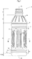
Fig. 1 ] is a side view showing a resin made container (first embodiment), - [
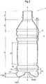
Fig. 2 ] shows a vertical section of the resin made container along an arrow line of sight II-II inFig. 1 , - [
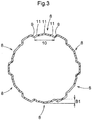
Fig. 3 ] shows a horizontal section of the resin made container along an arrow line of sight III-III inFig. 1 , - [
Fig. 4 ] is a side view of the resin made container (first embodiment) at the time of decompression absorption by a decompression absorption portion, - [
Fig. 5 ] shows a vertical section of the resin made container along an arrow line of sight V-V inFig. 4 , - [
Fig. 6 ] shows a horizontal section of the resin made container along an arrow line of sight VI-VI inFig. 4 , - [
Fig. 7 ] is a view showing in enlargement a further form of the decompression absorption portion in the resin made container (first embodiment), - [
Fig. 8 ] is a side view showing a resin made container (second embodiment), and - [
Fig. 9 ] shows a horizontal section of the resin made container along an arrow line of sight IX-IX inFig. 8 . - Next, as a preferred embodiment of the resin made container relating to the present invention, with reference to the accompanying drawings, there will be explained a
plastic bottle 1 in which liquid such as beverage is to be hot-pack filled. - First, various terms to be used in this detailed description will be defined as follows.
- In this detailed disclosure, the term "vertical direction" means the direction of center axis X-X of the
plastic bottle 1 inFig. 1 (to be referred to shortly as "bottle 1" hereinafter). In particular, inFigs. 1-3 , the upper side denotes the upper end side in the drawings and the lower side denotes the lower end side in the drawings. - The term "lateral direction" or "horizontal direction" means the direction perpendicular to the center axis X-X.
- The term "circumferential direction" means the direction along the contour of the horizontal sectional shape.
- The term "radial direction" means the radial direction of a circle having the center axis X-X as its center.
- The term "height" means the length along the center axis X-X.
- The term "depth" means the length along the radial direction.
- The term "horizontal sectional shape" means the sectional shape of the
bottle 1 in a plane (horizontal cross sectional plane) perpendicular to the center axis X-X. - The term "vertical sectional shape" means the sectional shape of the
bottle 1 in a plane (vertical cross sectional plane) along the center axis X-X. - As shown in
Fig. 1 andFig. 2 , thebottle 1 relating to the instant embodiment includes, in the order from the upper side, a spout (mouth)portion 2 to/from which a cap can be attached/detached, ashoulder portion 3 continuous with thespout portion 2, abody portion 4 continuous with theshoulder portion 3, and abottom portion 5 continuous with thebody portion 4 and disposed at the lowermost part. Further, thebottle 1 relating to the instant embodiment is a cylindrical container having an approximately circular horizontal section. - The
bottle 1 can be manufactured e.g. by a known molding method such as the biaxial stretch blow molding method with using a thermoplastic resin such as polyethylene, polypropylene, polyethylene terephthalate, etc. as a principal material. - The liquid to be filled in the
bottle 1 is not particularly limited. For instance, drinks such as drinking water, tea, juice, coffee, cocoa, soft beverage, alcohol beverage, milk-based drink, soup, or liquid condiment such as source, soy source, etc. can be cited. Further, the internal capacity of thebottle 1 is not particularly limited, either. In accordance with the type of liquid to be filled therein, it may be of a relatively small internal capacity in the order of a few hundreds of milliliters or of a relative large internal capacity in the order of a few litters, as desired. In case thebottle 1 is used as a beverage bottle, it is preferred that its internal capacity be set from 30 mL to 400 mL. Further, respecting the weight/internal capacity of thebottle 1 according to the instant embodiment, it may be set to 50 g/L or less. In particular, in the case of an internal capacity of 350 mL (=0.35L), its weight can be set to 15 g or less, also. - The
spout portion 2 is a portion constituted of a cylinder having its upper end opened and functions as a "spout" for beverage/drink, etc. In the outer circumferential face of thisspout portion 2, male thread is formed, to which an unillustrated cap is fixedly threaded detachably. - The
shoulder portion 3 is an approximately conical-shaped portion having its diameter progressively and continuously increased from its upper end to the lower side. Incidentally, in theshoulder portion 3 in the instant embodiment, a plurality ofvertical grooves 18 are formed in the circumferential direction by predetermined intervals. - The
body portion 4 is a cylindrical portion having an approximately circular horizontal cross section and has the largest outside diameter in thebottle 1. Further, in the outer circumferential face of thisbody portion 4, a label that shows e.g. the brand of the drink can be provided. In thebody portion 4 of the instant embodiment, a firstcircumferential groove 6 and a secondcircumferential groove 7 for reinforcement are provided at upper portions of thebody portion 4. Incidentally, the depth of the firstcircumferential groove 6 is shallower than the depth of the secondcircumferential groove 7; and also the maximum vertical width of the firstcircumferential groove 6 is smaller than the maximum vertical width of the secondcircumferential groove 7. - Vertically elongate
decompression absorption portions 8 are provided downwardly of the secondcircumferential groove 7 in the form of recesses by predetermined intervals in the circumferential direction. Eachdecompression absorption portion 8 includes, at its portion surrounded by itsinner side face 9, a bulgingarea 10 protruding to the outer side of the container. - As shown in
Fig. 2 , the bulgingarea 10 is curved such that its vertical sectional shape is curved to protrude to the outer side of the container. Further, as shown inFig. 3 , a horizontal sectional shape of the bulgingarea 10 is curved to protrude to the outer side of the container. - At the left and right opposed end portions and the central portion in the horizontal width direction of the bulging
area 10, there are respectively providedridge portions 11 extending in the vertical direction. In the instant embodiment, threesuch ridge portions 11 are provided in the bulgingarea 10. However, the invention is not limited thereto. Instead, as shown inFig. 7 for instance,such ridge portion 11 may be provided only at the central portion in the horizontal width direction of the bulgingarea 10. - As shown in
Fig. 1 andFig. 2 , thebottle 1 includes, at a portion downwardly of thedecompression absorption portions 8, acushion portion 12 which is elastically deformable in the vertical direction. Thiscushion portion 12 is configured as a bellows-like portion including a V-shapedcircumferential groove portion 13 whose width progressively increases toward the radial outer side and having a V-shaped vertical sectional shape and two smallcircumferential groove portions 14 provided upwardly and downwardly of the V-shapedcircumferential groove portion 13 respectively. And, thiscushion portion 12 has a line-symmetrical structure having the V-shapedcircumferential groove portion 13 as its axis of symmetry, as seen in the vertical cross section. Incidentally, the depth of the V-shapedcircumferential groove portion 13 is greater than the depth of the smallcircumferential groove 14; and the maximum vertical width of the the V-shapedcircumferential groove portion 13 is greater than the maximum vertical width of the smallcircumferential groove portion 14. Thus, thecushion portion 12 is configured as a three-stepped spring structure having three grooves consisting of the V-shapedcircumferential groove portion 13 and the two smallcircumferential groove portions 14. With this, its elastic deformation in the vertical direction is made possible. Incidentally, thiscushion portion 12 may be provided only when needed. - As shown in
Fig. 2 , in thebottom portion 5, arecess portion 15 which is receded in a chevron-shape protruding to the inner side of the container, abottom face 16 which comes into contact with an installation face when thebottle 1 is placed erect and acurved portion 17 which is curved toward the outer side from thebottom face 16 to thebody portion 4 are provided continuously. Thebottom face 16 has an annular shape as seen its plan view and is disposed in the outer circumference of therecess portion 15. -
Figs. 1 through 3 show thebottle 1 under a normal condition prior to occurrence of decompression absorption by thedecompression absorption portions 8.Figs. 4 through 6 show thebottle 1 undergoing decompression absorption through curved deformation of the bulgingareas 10 of thedecompression absorption portions 8 due to e.g. an internal pressure change by hot pack filling or volumetric change in the contents liquid associated with permeation over time of water content thereof, etc., in which the decompression absorption occurs with curved displacement of retraction to the inner side of the bulgingareas 10 in thedecompression absorption portions 8. - As shown in
Fig. 2 ,Fig. 3 ,Fig. 5 andFig. 6 , a bulging amount B1 of the bulgingarea 10 of thebottle 1 under the normal condition is greater than a bulging amount B2 of this bulgingarea 10 of thebottle 1 at the time of decompression absorption (B1>B2). - In the
bottle 1 filled by the hot pack technique with e.g. beverage, decompression absorption occurs. Therefore, normallysuch bottle 1 will be distributed/sold under the conditions shown inFigs. 4-6 . In this, if a shock or a load is applied to thebottle 1 from the vertical direction, the bulgingarea 10 of thedecompression absorption portion 8 tries to return to its original shape shown inFigs. 1-3 , thus bulging to the outer side of the container, whereby the shock/load can be absorbed. Therefore, by providing the bulgingarea 10 in thedecompression absorption portion 8, the buckling resistance of thebottle 1 can be enhanced. Further, since the above-described action of the bulgingarea 10 manifests itself the more efficiently, the thinner thebottle 1 becomes. Thus, further weight reduction of thebottle 1 is made possible. - Further, the
bottle 1 relating to the instant embodiment is provided, at a position downwardly of thedecompression absorption portions 8, with thecushion portion 12 that is elastically deformable in the vertical direction. In this case, at the time of application of a shock/load to thebottle 1 from the vertical direction, after bulging of the bulgingarea 10 of thedecompression absorption portion 8 to the outer side of the container, an action of elastic deformation of thecushion portion 12 occurs. With this action, the shock/load absorbing ability of thecushion portion 12 is improved over the case providing nodecompression absorption portions 8. Accordingly, there will be provided an even greater shock/load absorption ability than the case of simple added-up combination of the shock/load absorption ability of thedecompression absorption portion 8 and the shock/load absorption ability of thecushion portion 12. As a result, the buckling resistance of thebottle 1 can be enhanced dramatically. - Next, respecting a second embodiment of the present invention, with reference to the accompanying drawings, there will be described a
plastic bottle 1 having a liquid such as beverage filled thereby by aseptic room temperature filling method. In the following discussion, explanation of the same arrangements as those of the foregoing first embodiment will be omitted and explanation will be made mainly on different arrangements. - As shown in
Fig. 8 , thebottle 1 relating to the instant embodiment includes, in the order from the upper side, a spout (mouth)portion 2 to/from which a cap can be attached/detached, ashoulder portion 3 continuous with thespout portion 2, abody portion 4 continuous with theshoulder portion 3, and abottom portion 5 continuous with thebody portion 4 and disposed at the lowermost part. Further, thebottle 1 relating to the instant embodiment is a cylindrical container having an approximately circular horizontal section. - The
body portion 4 in this embodiment has its diameter progressively reduced from its upper end to the lower side and and then increased continuously from a position at the approximately half of thebody 4 in the vertical direction to be eventually formed continuous with thebottom portion 5. - In the
body portion 4, a plurality ofdecompression absorption portions 8 are provided in the form of recesses in the circumferential direction and by predetermined intervals. Incidentally, thedecompression absorption portions 8 in the instant embodiment are provided as recesses which extend between and across both the upper half and the lower half of thebody portion 4. Agroove 19 having a V-shaped cross section is formed along the contour of eachdecompression absorption portion 8 and thisgroove 19 at the upper end of thedecompression absorption portion 8 is formed continuous with the lateral face of thebody portion 4. - The
decompression absorption portion 8 includes, at a portion thereof surrounded by thegroove 19, a bulgingarea 10 formed to protrude to the outer side of the container. In the bulgingarea 10, a taperedarea 20 having a horizontal width progressively decreasing toward the upper side and a depth progressively decreasing toward the upper side, aconstant area 21 having a constant horizontal width equal to the maximum horizontal width of the taperedarea 20, and anenlarged area 22 having a horizontal width progressively increasing from theconstant area 21 are formed continuously in this order from the upper side. In the instant embodiment, the taperedarea 20 is provided at an upper half of thebody portion 4. Incidentally, a ratio of the area of the bulgingarea 10 relative to the total surface area of thebottle 1 ranges approximately from 30% to 45%, preferably. - As shown in
Fig. 9 , the horizontal cross sectional shape of the bulgingarea 10 is curved to protrude to the outer side of the container. Further, though not shown, the vertical cross sectional shape of the bulgingarea 10 is also curved to protrude to the outer side of the container. - In case the
bottle 1 relating to the instant embodiment is used as a beverage bottle, preferably, supposing its capacity ranging from 500 mL to 550 mL, its weight should range from 18g to 21g. In this case, preferably, in order to allow for more reliable curved displacement of the bulgingarea 10 to the inner side of the bottle at the time of decompression absorption, the curvature radius of the horizontal cross sectional shape of the bulgingarea 10 of thisbottle 1 under its normal condition should range greater than 0 mm (0R) and less than 80 mm (80R), more preferably greater than 0 mm (0R) and less than about 50 mm (50R), and most preferably greater than 0 mm (0R) and less than about 27 mm (27R). Also, the curvature radius of the vertical cross sectional shape of the bulgingarea 10 of thebottle 1 under the normal condition is e.g. about 900 mm (900R). - The bulging amount B1 of the bulging
area 10 under the normal condition of thebottle 1 is preferably less than 1 mm, more preferably equal to or less than 0.75 mm, still more preferably equal to or less than about 0.5 mm. The beverage bottle configured as described above has higher buckling resistance and decompression absorption ability even when the thickness of the bottle is decreased. - Incidentally, though not shown, the above-described
decompression absorption portion 8 may be vertically inverted. In this case, the taperedarea 20, theconstant area 21 and theenlarged area 22 will be formed continuous from the lower side in this order, and thegroove 19 at the lower end of thedecompression absorption portion 8 will be formed continuous with the lateral face of thebody portion 4. Also, the taperedarea 20 will be provided in the lower half of thebody portion 4. - In the
decompression absorption portion 8, there is formed arecess portion 23 receded to the inner side of the container. In this embodiment, in particular, arecess 23 having a rhombus square pyramid shape is formed between a part of theconstant area 21 and a part of theenlarged area 22. However, the shape and the setting position of theconcave portion 23 are not limited to the above. Incidentally, in thedecompression absorption portion 8, instead of therecess portion 23, a protrusion portion protruding to the outer side of the container may be formed. In this case too, similarly to the case of therecess portion 23, a protrusion portion having a rhombus square pyramid shape may formed between a part of theconstant area 21 and a part of theenlarged area 22. However, the shape and the setting position of the protrusion portion are not limited to the above. - In connection with the
bottle 1 relating to the second embodiment described above, three kinds of PET bottles shown in Table 1 below were made and bucking resistances thereof were checked. Meanwhile, all of these bottles had a weight of 18.3g. Further, the bulging amounts B1 of the bulgingareas 10 and the curvature radii of the horizontal cross sectional shapes of the bulgingareas 10 of all of these bottles were values measured at the vertically approximately middle positions of the bulgingportions 10 and the curvature radii of the vertical cross sectional shapes of the bulgingareas 10 were values measured at the center portions dividing the bulgingareas 10 into the left sides and the right sides equally.[Table 1] Comparison Example Example 1 Example 2 bulging amount B1 (mm) of bulging area 100.0 (flat face shape) 0.5 1.0 curvature radius (mm) of horizontal cross sectional shape of bulging area 100.0 80.0 26.8 curvature radius (mm) of vertical cross sectional shape of bulging area 10900 900 900 bucking resistance × ○ ○ - As shown in Table 1, the PET bottles of Example 1 and Example 2 were able to withstand a pressure of 200 N or greater. Whereas, the PET bottle of Comparison Example 1 was unable to withstand the pressure of 200 N or greater and buckled
- The resin made container of the present invention can be used suitably as a container to be sealingly filled with a beverage or the like or a condiment or the like.
-
- 1:
- bottle
- 2:
- spout portion
- 3:
- shoulder portion
- 4:
- body portion
- 5:
- bottom portion
- 6:
- first circumferential groove
- 7:
- second circumferential groove
- 8:
- decompression absorption portion
- 9:
- inner side face
- 10:
- bulging area
- 11:
- ridge portion
- 12:
- cushion portion
- 13:
- V-shaped circumferential groove portion
- 14:
- small circumferential groove portion
- 15:
- recess portion
- 16:
- bottom face
- 17:
- curved portion
- 18:
- vertical groove
- 19:
- groove
- 20:
- tapered area
- 21:
- constant area
- 22:
- enlarged area
- 23:
- recess portion
- B1:
- bulging amount at normal time
- B2:
- bulging amount at time of decompression absorption
Claims (7)
- A resin made container comprising:a spout portion to/from which a cap can be attached/detached;a shoulder portion continuous with the spout portion;a body portion continuous with the shoulder portion; anda bottom portion continuous with the body portion and disposed at a lowermost part;wherein a decompression absorption portion provided in form of a recess in the body portion includes a bulging area protruding to the outer side of the container.
- The resin made container of claim 1, wherein a vertical sectional shape of the bulging area is curved to protrude to the outer side of the container.
- The resin made container of claim 1 or 2, wherein a horizontal sectional shape of the bulging area is curved to protrude to the outer side of the container.
- The resin made container of any one of claims 1-3, wherein downwardly of the decompression absorption portion, there is provided a cushion portion that is elastically deformable in the vertical direction.
- The resin made container of any one of claims 1-4, wherein the container has a weight/internal capacity of 50g/L or less.
- The resin made container of any one of claims 1-5, wherein the bulging portion has a bulging amount less than 1 mm.
- The resin made container of any one of claims 1-6, wherein a horizontal cross sectional shape of the bulging area has a curvature radius less than 80 mm.
Applications Claiming Priority (2)
| Application Number | Priority Date | Filing Date | Title |
|---|---|---|---|
| JP2017037055A JP2018140824A (en) | 2017-02-28 | 2017-02-28 | Resin container |
| PCT/JP2018/007325 WO2018159630A1 (en) | 2017-02-28 | 2018-02-27 | Resin container |
Publications (2)
| Publication Number | Publication Date |
|---|---|
| EP3590855A1 true EP3590855A1 (en) | 2020-01-08 |
| EP3590855A4 EP3590855A4 (en) | 2021-01-27 |
Family
ID=63370680
Family Applications (1)
| Application Number | Title | Priority Date | Filing Date |
|---|---|---|---|
| EP18760683.5A Withdrawn EP3590855A4 (en) | 2017-02-28 | 2018-02-27 | Resin container |
Country Status (6)
| Country | Link |
|---|---|
| US (1) | US11261002B2 (en) |
| EP (1) | EP3590855A4 (en) |
| JP (1) | JP2018140824A (en) |
| CN (1) | CN110352164A (en) |
| AU (1) | AU2018227161A1 (en) |
| WO (1) | WO2018159630A1 (en) |
Families Citing this family (10)
| Publication number | Priority date | Publication date | Assignee | Title |
|---|---|---|---|---|
| JP7214425B2 (en) * | 2018-10-10 | 2023-01-30 | エステー株式会社 | liquid container |
| JP7586755B2 (en) * | 2021-04-01 | 2024-11-19 | サントリーホールディングス株式会社 | Plastic Bottles |
| US11628966B2 (en) * | 2021-04-12 | 2023-04-18 | Dart Industries Inc. | Freezable and reusable bottle and method of making the bottle |
| JP7822185B2 (en) * | 2022-01-20 | 2026-03-02 | アサヒ飲料株式会社 | Plastic bottles and beverage products |
| US12054304B2 (en) * | 2022-06-03 | 2024-08-06 | Abbott Laboratories | Reclosable plastic bottle with waist and strengthening rib(s) |
| USD1076674S1 (en) * | 2022-09-02 | 2025-05-27 | Vollgas Beverage (Shanghai) Co., Ltd. | Bottle |
| USD1075510S1 (en) * | 2023-03-01 | 2025-05-20 | Vollgas Beverage (Shanghai) Co., Ltd. | Bottle |
| USD1075511S1 (en) * | 2023-03-01 | 2025-05-20 | Vollgas Beverage (Shanghai) Co., Ltd. | Bottle |
| WO2025257417A1 (en) * | 2024-06-14 | 2025-12-18 | Khs Gmbh | Plastic container, and method for forming a filled pet beverage bottle |
| USD1126002S1 (en) | 2024-10-08 | 2026-05-12 | Co2Pac Limited | Container |
Family Cites Families (16)
| Publication number | Priority date | Publication date | Assignee | Title |
|---|---|---|---|---|
| AUPN605595A0 (en) | 1995-10-19 | 1995-11-09 | Amcor Limited | A hot fill container |
| US7137520B1 (en) * | 1999-02-25 | 2006-11-21 | David Murray Melrose | Container having pressure responsive panels |
| JP4201100B2 (en) | 2000-01-25 | 2008-12-24 | 株式会社吉野工業所 | Plastic bottle |
| JP3826830B2 (en) * | 2002-04-12 | 2006-09-27 | 東洋製罐株式会社 | Biaxial stretch blow molded container |
| JP2006290388A (en) * | 2005-04-08 | 2006-10-26 | Toyo Seikan Kaisha Ltd | Container |
| US7458478B2 (en) * | 2007-01-17 | 2008-12-02 | Constar International Inc. | Hot-fillable container with convex sidewall areas that deform under vacuum conditions |
| JP5057306B2 (en) * | 2008-01-31 | 2012-10-24 | 株式会社吉野工業所 | Synthetic resin housing |
| US8286814B2 (en) * | 2008-04-17 | 2012-10-16 | Graham Packaging Company, L.P. | Volumetrically efficient hot-fill type container |
| US9102434B2 (en) * | 2009-07-20 | 2015-08-11 | Graham Packaging Company, L.P. | Container having compound flexible panels |
| JP5584929B2 (en) | 2010-12-17 | 2014-09-10 | サントリーホールディングス株式会社 | Resin container |
| JP5793300B2 (en) * | 2010-12-28 | 2015-10-14 | 株式会社吉野工業所 | Bottle |
| JP6060497B2 (en) * | 2012-02-28 | 2017-01-18 | 大日本印刷株式会社 | Plastic bottle |
| JP6623520B2 (en) | 2015-01-22 | 2019-12-25 | 大日本印刷株式会社 | Plastic bottle |
| JP6427017B2 (en) * | 2015-01-28 | 2018-11-21 | 北海製罐株式会社 | Plastic bottle |
| JP6798770B2 (en) * | 2015-06-30 | 2020-12-09 | 株式会社吉野工業所 | Round bottle |
| JP6510357B2 (en) * | 2015-07-30 | 2019-05-08 | 株式会社吉野工業所 | Plastic container |
-
2017
- 2017-02-28 JP JP2017037055A patent/JP2018140824A/en active Pending
-
2018
- 2018-02-27 WO PCT/JP2018/007325 patent/WO2018159630A1/en not_active Ceased
- 2018-02-27 CN CN201880014235.2A patent/CN110352164A/en active Pending
- 2018-02-27 AU AU2018227161A patent/AU2018227161A1/en not_active Abandoned
- 2018-02-27 US US16/483,162 patent/US11261002B2/en active Active
- 2018-02-27 EP EP18760683.5A patent/EP3590855A4/en not_active Withdrawn
Also Published As
| Publication number | Publication date |
|---|---|
| CN110352164A (en) | 2019-10-18 |
| JP2018140824A (en) | 2018-09-13 |
| AU2018227161A2 (en) | 2019-09-12 |
| EP3590855A4 (en) | 2021-01-27 |
| AU2018227161A1 (en) | 2019-08-15 |
| WO2018159630A1 (en) | 2018-09-07 |
| US20200002045A1 (en) | 2020-01-02 |
| US11261002B2 (en) | 2022-03-01 |
Similar Documents
| Publication | Publication Date | Title |
|---|---|---|
| US11261002B2 (en) | Resin made container | |
| US9714109B2 (en) | Resin container | |
| AU2013355934B2 (en) | Resin container | |
| AU720439B2 (en) | A hot fill container | |
| US7416090B2 (en) | Round type hot fillable container with deformable label panel | |
| EP2331412B1 (en) | Plastic bottle | |
| US10053275B2 (en) | Deformation-resistant container with panel indentations | |
| AU2011342160A1 (en) | Resin container | |
| AU2019362752B2 (en) | Plastic bottle with base | |
| CN110114276A (en) | Resin container | |
| JP2605807Y2 (en) | Synthetic resin bottle | |
| JP6756100B2 (en) | Synthetic resin container | |
| EP3763630B1 (en) | Plastic bottle | |
| EP3564141A1 (en) | Resin container | |
| JP6353947B2 (en) | Resin container | |
| EP3763627B1 (en) | Plastic bottle | |
| JP7455081B2 (en) | plastic bottle | |
| JP4992329B2 (en) | Plastic container | |
| EP3763629B1 (en) | Plastic bottle | |
| JP6999265B2 (en) | Resin container | |
| HK1158156B (en) | Plastic bottle |
Legal Events
| Date | Code | Title | Description |
|---|---|---|---|
| STAA | Information on the status of an ep patent application or granted ep patent |
Free format text: STATUS: THE INTERNATIONAL PUBLICATION HAS BEEN MADE |
|
| PUAI | Public reference made under article 153(3) epc to a published international application that has entered the european phase |
Free format text: ORIGINAL CODE: 0009012 |
|
| STAA | Information on the status of an ep patent application or granted ep patent |
Free format text: STATUS: REQUEST FOR EXAMINATION WAS MADE |
|
| 17P | Request for examination filed |
Effective date: 20190928 |
|
| AK | Designated contracting states |
Kind code of ref document: A1 Designated state(s): AL AT BE BG CH CY CZ DE DK EE ES FI FR GB GR HR HU IE IS IT LI LT LU LV MC MK MT NL NO PL PT RO RS SE SI SK SM TR |
|
| AX | Request for extension of the european patent |
Extension state: BA ME |
|
| DAV | Request for validation of the european patent (deleted) | ||
| DAX | Request for extension of the european patent (deleted) | ||
| A4 | Supplementary search report drawn up and despatched |
Effective date: 20210114 |
|
| RIC1 | Information provided on ipc code assigned before grant |
Ipc: B65D 1/02 20060101AFI20201223BHEP Ipc: B65D 79/00 20060101ALI20201223BHEP |
|
| STAA | Information on the status of an ep patent application or granted ep patent |
Free format text: STATUS: THE APPLICATION IS DEEMED TO BE WITHDRAWN |
|
| 18D | Application deemed to be withdrawn |
Effective date: 20210813 |