EP3590802B1 - Bicycle with kickstand and dropout of a bicycle frame - Google Patents
Bicycle with kickstand and dropout of a bicycle frame Download PDFInfo
- Publication number
- EP3590802B1 EP3590802B1 EP19184367.1A EP19184367A EP3590802B1 EP 3590802 B1 EP3590802 B1 EP 3590802B1 EP 19184367 A EP19184367 A EP 19184367A EP 3590802 B1 EP3590802 B1 EP 3590802B1
- Authority
- EP
- European Patent Office
- Prior art keywords
- bicycle frame
- incorporates
- accordance
- bicycle
- guide contour
- Prior art date
- Legal status (The legal status is an assumption and is not a legal conclusion. Google has not performed a legal analysis and makes no representation as to the accuracy of the status listed.)
- Active
Links
- 239000002184 metal Substances 0.000 claims description 5
- 230000000694 effects Effects 0.000 description 5
- 238000004519 manufacturing process Methods 0.000 description 3
- 230000010354 integration Effects 0.000 description 2
- 239000000463 material Substances 0.000 description 2
- 230000000295 complement effect Effects 0.000 description 1
- 230000001419 dependent effect Effects 0.000 description 1
- 230000009760 functional impairment Effects 0.000 description 1
- 238000003698 laser cutting Methods 0.000 description 1
- 238000003801 milling Methods 0.000 description 1
- 230000008092 positive effect Effects 0.000 description 1
Images


Classifications
-
- B—PERFORMING OPERATIONS; TRANSPORTING
- B62—LAND VEHICLES FOR TRAVELLING OTHERWISE THAN ON RAILS
- B62H—CYCLE STANDS; SUPPORTS OR HOLDERS FOR PARKING OR STORING CYCLES; APPLIANCES PREVENTING OR INDICATING UNAUTHORIZED USE OR THEFT OF CYCLES; LOCKS INTEGRAL WITH CYCLES; DEVICES FOR LEARNING TO RIDE CYCLES
- B62H1/00—Supports or stands forming part of or attached to cycles
- B62H1/02—Articulated stands, e.g. in the shape of hinged arms
-
- B—PERFORMING OPERATIONS; TRANSPORTING
- B62—LAND VEHICLES FOR TRAVELLING OTHERWISE THAN ON RAILS
- B62K—CYCLES; CYCLE FRAMES; CYCLE STEERING DEVICES; RIDER-OPERATED TERMINAL CONTROLS SPECIALLY ADAPTED FOR CYCLES; CYCLE AXLE SUSPENSIONS; CYCLE SIDE-CARS, FORECARS, OR THE LIKE
- B62K19/00—Cycle frames
- B62K19/30—Frame parts shaped to receive other cycle parts or accessories
- B62K19/40—Frame parts shaped to receive other cycle parts or accessories for attaching accessories, e.g. article carriers, lamps
Definitions
- the invention relates to a bicycle frame according to the preamble of claim 1.
- a bicycle frame which constitutes the closest prior art.
- Two mutually oblique, straight surfaces of a base provided on the bicycle frame form contact surfaces against which a spring-loaded pressure piece of a support of the bicycle stand rests in either the standing position or the driving position of the support.
- the invention has for its object to improve a generic bicycle frame to the effect that this one supports the most economical production of the bicycle.
- the invention proposes that the base be designed as part of a rear-end dropout of the bicycle frame, which is simply referred to as a dropout.
- the bicycle frame is typically made from a plurality of tubes, but the dropouts are typically manufactured as sheet metal blanks from sheet material, such as by stamping, milling, or laser cutting operations.
- the guide contour can therefore be implemented in the base without having to create an additional component. This is not only advantageous in terms of the number of different parts, but also requires no additional assembly step. Rather, during the manufacture of the bicycle frame, the base of the bicycle stand is also installed at the same time as the dropout must be installed anyway.
- a further advantageous effect is that on bicycles on which no bicycle stand is to be mounted, the integration of the base into the dropout creates hardly any disruptive protrusions, compared to a base which is arranged on a chainstay of the bicycle frame, for example.
- this relates to the aesthetic effect that the unused base can have as a projection or overhang, which may be perceived as disturbing, but on the other hand also to the fact that body parts, clothing or the like can get caught on the unused projection.
- the base is shifted as far away as possible, for example from the circle on which the pedals are moved, and thus as far away as possible from the feet, shoelaces and trouser legs of a person using the bicycle.
- the dropout can advantageously consist of an angled plate material. This creates a first section of the dropout, which can be aligned exactly vertically, for example, and is used to hold the rear axle. A second section, which is angled in contrast, can be angled downwards and obliquely outwards and can have the guide contour. The angling causes the support to be spread outwards during its pivoting movement from the riding position to the standing position and thus, together with the two wheels, creates the largest possible footprint for the bicycle, defined by three contact points, which has a positive effect on the stability of the bicycle .
- Both troughs are each delimited by two edges running conically towards one another.
- the edge that is closer to the other trough in the course of the guide contour is referred to as the inner edge, and the other edge of a trough that is accordingly located at one end of the guide contour is referred to as the outer edge.
- the two outer edges each form a stop that limits the pivoting movement of the support.
- a clearly defined position of the support in its respective end position is achieved in that the stop runs essentially parallel to the direction of movement of the pressure piece, that is to say essentially transversely to the curved pivoting direction of the support.
- the pressure piece fills the respective trough in such a way that it rests against the two edges of the trough. Since the two edges of a trough run conically towards one another, the pressure piece, supported by the spring force, is always pressed as far as possible into the trough and into its correspondingly conical seat, so that it is held in the trough without play. As a result, the support is held in its respective end position without play. For the standing position, this means a particularly high level of stability of the bicycle, and for the driving position, this means a rattle-free mounting of the support even when driving over uneven ground.
- the direction of movement of the pressure piece can be offset relative to the pivot axis.
- the extension of the movement path, on which the central axis of the pressure piece is supported by spring force or runs counter to the direction of the spring, does not cross the pivot axis, but runs past the pivot axis.
- this offset is advantageously realized in such a way that the direction of movement of the pressure piece is offset downwards relative to the pivot axis when the support is in its driving position, this has an advantageous effect on the design degrees of freedom, since there is a larger one in the area of the rear wheel hub Space for drive or brake components is available, for example for electrical actuation of a gear shift.
- the strut can be broken down into three sections: a foot that supports it on the ground, a leg that makes up most of the length of the strut, and a head that connects the strut to the base, and with which it is pivotally mounted on the pivot axis.
- the base can advantageously be designed as a sheet metal blank and be encompassed by a head of the support, in that the head has a central recess and accordingly extends fork-like on both sides of the base.
- the base is configured as narrow and unobtrusively as possible in the event that the bicycle is not to be equipped with a bicycle stand and accordingly no support is mounted on the base.
- the spring acting on the pressure piece can be designed as an internal spring, so that it is optimally protected against external influences and any functional impairments associated therewith.
- the spring can advantageously be arranged in the head of the support, because while the leg is often designed as a tubular section, the head of a bicycle stand is often made as a separately manufactured die-cast or injection-molded component, so that there is no problem in creating areas in such a component , on which the spring is guided or supported.
- the spring acting on the pressure piece can advantageously be designed as a helical spring. Its longitudinal axis or central axis determines the direction of action of the spring and thus defines the direction of movement of the pressure piece.
- the configuration as a helical spring enables simple integration into the elongated shape of a support.
- the pressure piece can advantageously have a roof-shaped tip, with which it bears against the guide contour along the pivoting movement of the support. Even if the roof-shaped tip is preferably strongly rounded, there is a comparatively small contact surface between the pressure piece and the guide contour and thus low resistance and correspondingly low expenditure of force in order to be able to pivot the support between its two end positions relative to the base.
- the pressure piece has two abutment surfaces, one of which abuts against a stop when the support is in its two end positions.
- a comparatively large contact surface of the stop surfaces with the guide contour, namely with their respective stop, is made possible, so that the support can be reliably fixed and held in its respective end position.
- the dropout can have two parts, one of which has the guide contour.
- the dropouts usually have a number of connection points, which can be designed as through-holes, for example. Accordingly, the part having the guide contour can be designed in such a way that it can be connected to such connection points.
- a dropout can be modularly assembled from different components: one basic element of the dropout is always the same. On the one hand it connects to the seat and chainstays and on the other hand it has a mount for the rear axle. For bicycles that do not have a bicycle stand, a rear wheel mudguard or a rear wheel luggage rack, for example, this basic element can form the sole component of the dropout.
- the dropout is combined with a second part, for example welded, with this second part being able to have the connection points for a mudguard and/or a luggage rack and/or the guide contour of the proposed bicycle stand.
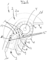
- FIG. 1 shows a perspective view of a bicycle stand 1.
- This has a base 2, indicated purely schematically, which is designed as an integral part of a bicycle frame, namely as an area of a dropout.
- the base 2 is part of a plate that is designed as a dropout of the bicycle frame. This plate is manufactured as a stamped part or as a laser cut from sheet metal with the usual sheet metal thickness for a dropout.
- the 2 and 3 show that the plate or the dropout has a first portion 2a, which is in a first, upright Level runs, namely in the illustrated embodiment in an exactly vertical plane.
- the opposite second dropout on the bicycle frame is also aligned vertically parallel thereto, and the rear axle of the bicycle is held in the vertical section 2a and the opposite dropout.
- the dropout has a second section 2b which runs in a second plane which is angled obliquely downwards and outwards to the first, perpendicular plane. This ensures that a foot 16 of the bicycle stand 1 in the standing position stands up on the ground to the side next to the bicycle frame and thus gives the bicycle a secure footing.
- the base 2 can have a contact surface with which it can be welded to a bicycle frame, for example to a chain stay.
- the curved shape on the upper edge of the base 2 is a purely schematically indicated delimitation of the vertical section 2a and in the illustrated embodiment is representative of the mentioned and also other conceivable configurations of the base 2.
- a support 3 of the bicycle stand 1 is movably mounted about a pivot axis 4 .
- the support 3 is designed to be telescopic so that it can be adapted to different bicycle frames.
- the standing position that can be seen represents a front end position of the support 3 in which the support 3 rests against a front stop 5 of the base 2 . From this front end position, the support 3 can be pivoted backwards about the pivot axis 4 until it assumes a horizontal driving position and in so doing rests against a rear stop 6 of the base 3 .
- a pressure piece 7 of the support 3 runs along a guide contour 8 of the base 2, the guide contour having the two stops 5 and 6 at its two ends.
- the support 3 has a head 18 at its upper end near the pivot axis 4, which grips the base 2, which is formed from a plate, like a fork on both sides and also encloses the pivot axis 4 in a ring on both of these sides .
- the pressure piece 7 is arranged in the head 18 and is pressed by a schematically indicated helical spring 9 in the direction of the pivot axis 4 and thus to bear against the guide contour 8 .
- the line of action of the helical spring 9 i.e. its imaginary central axis, does not run radially towards the pivot axis 4, but at a distance past the pivot axis 4, namely in front of the pivot axis 4 in the direction of travel of the bicycle.
- the pressure piece 7 To rest against the guide contour 8, the pressure piece 7 has a strongly rounded tip 19 with two flanks 11, which are arranged approximately A-shaped and are at an angle of approximately 90° to one another in the exemplary embodiment shown. Below the crest 19, ie closer to the foot 16 of the support 3, the pressure piece 7 has two outer stop surfaces 12 which abut the two stops 5 and 6 in the two end positions of the support 3. To guide the helical spring 9 , the pressure piece 7 has a mandrel 20 , the helical spring 9 being supported with its lower end, ie the end remote from the pivot axis 4 , on the head 18 or within the leg 10 .
- the pressure piece 7 dips into a trough, referred to as a standing trough 14 , in the guide contour 8 , the standing trough 14 being delimited by two contact surfaces 15 and extending between these two contact surfaces 15 .
- One contact surface 15 is formed by the front stop 5; a stop surface 12 of the pressure piece 7 rests on it.
- the other contact surface 15 is the edge 11 of the pressure piece 7 shown on the right, while a gap remains between the edge 11 shown on the left and the guide contour 8 within the trough 14 standing.
- the standing trough 14 is delimited by two conically running edges.
- the stop 5 represents an outer edge of the standing trough 14 because it forms one end of the entire guide contour 8, while the other contact surface 15 shown on the right is referred to as the inner edge. If wear occurs on the pressure piece 7 and/or on the guide contour 8, or if there are manufacturing tolerances, the helical spring 9 ensures that the pressure piece 7 is always pressed as far as possible and accordingly free of play into this conical seat, which the recess 14 creates for the pressure piece 7 .
- the stop 5 runs in the direction of movement of the pressure piece 7, so that the pressure piece 7 can slide along the stop 5, depending on wear or tolerance, until the right flank 11 of the pressure piece 7 touches the right contact surface 15 of the guide contour 8 is present.
- the stop 5 runs essentially parallel to the longitudinal axis of the support 3 or to the longitudinal axis of the helical spring 9.
- the stop 5 thus runs essentially transversely to the direction of movement, along which the support 3 can be moved about the pivot axis 4.
- the stop 5 therefore represents an effective limitation of the mobility of the support 3 and gives the bicycle parked by means of the bicycle stand 1 a high level of stability.
- the standing position shown represents one of the two end positions of the support 3. From the standing position, the support 3 can be pivoted counterclockwise about the pivot axis 4. Here, the pressure piece 7 follows with its tip 19 of the guide contour 8. Since the guide contour 8 following the stand trough 14 in an increasing Distance from the pivot axis 4 runs, the pressure piece 7 must be pressed against the action of the helical spring 9 in the direction of the foot 16 of the support 3 in order to be able to follow the guide contour 8 .
- the resistance thus created which tends to hinder the pivoting movement of the support 3, can be easily overcome by the user of the bicycle, but on the other hand ensures that the bicycle is stable even if the bicycle has been parked, for example, on a sloping surface in the direction of travel downhill is.
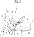
- the pressure piece 7 arrives along the guide contour 8 in a second trough, as shown in FIG 3 can be seen, this second trough being referred to as a driving trough 17 .
- This position of the support 3 is referred to as its driving position.
- the cradle 17 also has two contact surfaces 15 which each form an inner edge or outer edge delimiting the cradle 17 .
- the outer edge is created by the stop 6.
- the pressure piece 7 rests against this stop 6 with a stop surface 12, and similar to the standing trough 14, the stop 6 here also runs essentially parallel to the longitudinal axis of the support 3 or to the longitudinal axis of the helical spring 9, and in particular essentially transversely to the direction of movement. along which the support 3 has been pivoted about the pivot axis 4 into the trough 17 .
- FIG. 4 shows a side view of the pressure piece 7.
- the mandrel 20 extends much further down, i.e. away from the tip 19, than the two stop surfaces 12, so that a correspondingly long helical spring 9 can be used, which is, for example, significantly longer than schematic in 2 implied.
- figure 5 shows a view from below of the pressure piece 7. It is particularly clear that the two stop surfaces 12 grooves 21 connect. These cooperate with complementary ribs within the head 18 to To lead pressure piece 7 during movements along its direction of movement.
- the Figures 4 and 5 a safety lug 22, which projects laterally outwards on the pressure piece 7.
- the securing lug 22 limits how far the pressure piece 7 can be removed from the foot 16 of the support 3 by the helical spring 9 .
- a projection is provided inside the head 18, which limits this movement in that the securing lug 22 comes to rest on the projection. If, for example, the support 3 is removed from the base 2, the safety lug 22 prevents the pressure piece 7 from being shot out of the head 18 of the support 3 in an uncontrolled manner due to the spring effect.
Description
Die Erfindung betrifft einen Fahrradrahmen nach dem Oberbegriff des Anspruchs 1.The invention relates to a bicycle frame according to the preamble of
Aus der
Aus der
Der Erfindung liegt die Aufgabe zugrunde, einen gattungsgemäßen Fahrradrahmen dahingehend zu verbessern, dass dieser eine möglichst wirtschaftliche Herstellung des Fahrrads unterstützt.The invention has for its object to improve a generic bicycle frame to the effect that this one supports the most economical production of the bicycle.
Diese Aufgabe wird durch einen Fahrradrahmen nach Anspruch 1 gelöst sowie durch ein Ausfallende nach Anspruch 11.This object is achieved by a bicycle frame according to
Vorteilhafte Ausgestaltungen sind in den Unteransprüchen beschrieben.Advantageous configurations are described in the dependent claims.
Die Erfindung schlägt mit anderen Worten vor, dass der Sockel als Teil eines Hinterbau-Ausfallendes des Fahrradrahmens ausgestaltet ist, welches kurz lediglich als Ausfallende bezeichnet wird. Der Fahrradrahmen besteht typischerweise aus einer Vielzahl von Rohren, während jedoch die Ausfallenden typischerweise als Blechzuschnitte aus einem Plattenmaterial hergestellt werden, beispielsweise durch Stanz-, Fräs- oder Laserschneidvorgänge. Daher kann die Führungskontur im Sockel verwirklicht werden, ohne ein zusätzliches Bauteil schaffen zu müssen. Dies ist nicht nur hinsichtlich der Anzahl unterschiedlicher Teile vorteilhaft, sondern erfordert auch keinen zusätzlichen Montageschritt. Vielmehr wird während der Herstellung des Fahrradrahmens durch die ohnehin erforderliche Montage des Ausfallendes gleichzeitig auch der Sockel des Fahrradständers montiert.In other words, the invention proposes that the base be designed as part of a rear-end dropout of the bicycle frame, which is simply referred to as a dropout. The bicycle frame is typically made from a plurality of tubes, but the dropouts are typically manufactured as sheet metal blanks from sheet material, such as by stamping, milling, or laser cutting operations. The guide contour can therefore be implemented in the base without having to create an additional component. This is not only advantageous in terms of the number of different parts, but also requires no additional assembly step. Rather, during the manufacture of the bicycle frame, the base of the bicycle stand is also installed at the same time as the dropout must be installed anyway.
Als weiterer vorteilhafter Effekt ergibt sich, dass bei Fahrrädern, bei denen kein Fahrradständer montiert werden soll, die Integration des Sockels in das Ausfallende kaum störende Überstände schafft, verglichen mit einem Sockel, der beispielsweise an einer Kettenstrebe des Fahrradrahmens angeordnet ist. Dies betrifft einerseits die ästhetische, ggf. als störend empfundene Wirkung, die der ungenutzte Sockel als Vorsprung bzw. Überstand aufweisen kann, andererseits aber auch den Umstand, dass an dem ungenutzten Vorsprung Körperteile, Kleidung oder dergleichen hängen bleiben können. Durch die Integration in das Ausfallende wird der Sockel möglichst weit weg beispielsweise von dem Kreis verlagert, auf dem die Pedalen bewegt werden, und somit möglichst weit weg von Füßen, Schnürsenkeln und Hosenbeinen einer das Fahrrad benutzenden Person.A further advantageous effect is that on bicycles on which no bicycle stand is to be mounted, the integration of the base into the dropout creates hardly any disruptive protrusions, compared to a base which is arranged on a chainstay of the bicycle frame, for example. On the one hand, this relates to the aesthetic effect that the unused base can have as a projection or overhang, which may be perceived as disturbing, but on the other hand also to the fact that body parts, clothing or the like can get caught on the unused projection. By integrating it into the dropout, the base is shifted as far away as possible, for example from the circle on which the pedals are moved, and thus as far away as possible from the feet, shoelaces and trouser legs of a person using the bicycle.
Vorteilhaft kann das Ausfallende aus einem abgewinkelten Plattenmaterial bestehen. Hierdurch wird ein erster Abschnitt des Ausfallendes geschaffen, der beispielsweise exakt senkrecht ausgerichtet sein kann und zur Aufnahme der Hinterachse dient. Ein zweiter, demgegenüber abgewinkelter Abschnitt kann nach unten und schräg nach außen abgewinkelt sein und die Führungskontur aufweisen. Durch die Abwinklung wird bewirkt, dass die Stütze bei ihrer Schwenkbewegung aus der Fahrstellung in die Standstellung nach außen abgespreizt wird und so zusammen mit den beiden Laufrädern eine möglichst große, durch drei Aufstandspunkte definierte Stellfläche für das Fahrrad schafft, was die Standsicherheit des Fahrrades positiv beeinflusst.The dropout can advantageously consist of an angled plate material. This creates a first section of the dropout, which can be aligned exactly vertically, for example, and is used to hold the rear axle. A second section, which is angled in contrast, can be angled downwards and obliquely outwards and can have the guide contour. The angling causes the support to be spread outwards during its pivoting movement from the riding position to the standing position and thus, together with the two wheels, creates the largest possible footprint for the bicycle, defined by three contact points, which has a positive effect on the stability of the bicycle .
Vorteilhaft kann vorgesehen sein, in der Führungskontur für die beiden Endstellungen der Stütze zwei Mulden anzuordnen, in welche jeweils das Druckstück der Stütze eintauchen kann, wenn die Stütze in ihre jeweilige Standstellung oder Fahrstellung geschwenkt worden ist. Beide Mulden werden jeweils durch zwei konisch zueinander verlaufende Ränder begrenzt. Jeweils der Rand, der im Verlauf der Führungskontur der jeweils anderen Mulde näher benachbart ist, wird als Innenrand bezeichnet, und der jeweils andere Rand einer Mulde, der sich dementsprechend an einem Ende der Führungskontur befindet, wird als Außenrand bezeichnet.Provision can advantageously be made to arrange two troughs in the guide contour for the two end positions of the support, into which the pressure piece of the support can immerse when the support has been pivoted into its respective standing position or driving position. Both troughs are each delimited by two edges running conically towards one another. The edge that is closer to the other trough in the course of the guide contour is referred to as the inner edge, and the other edge of a trough that is accordingly located at one end of the guide contour is referred to as the outer edge.
Die beiden Außenränder bilden bei dieser vorteilhaften Ausgestaltung jeweils einen Anschlag, der die Schwenkbewegung der Stütze begrenzt. Eine klar definierte Stellung der Stütze in ihrer jeweiligen Endstellung wird dadurch erreicht, dass der Anschlag im Wesentlichen parallel zur Bewegungsrichtung des Druckstücks verläuft, also im Wesentlichen quer zur bogenförmigen Schwenkrichtung der Stütze.In this advantageous embodiment, the two outer edges each form a stop that limits the pivoting movement of the support. A clearly defined position of the support in its respective end position is achieved in that the stop runs essentially parallel to the direction of movement of the pressure piece, that is to say essentially transversely to the curved pivoting direction of the support.
Weiterhin ist bei dieser vorteilhaften Ausgestaltung vorgesehen, dass das Druckstück die jeweilige Mulde in der Art ausfüllt, dass es den beiden Rändern der Mulde anliegt. Da die beiden Ränder einer Mulde konisch zueinander verlaufen, wird das Druckstück, von der Federkraft unterstützt, stets so weit wie möglich in die Mulde und in seinen dementsprechend konischen Sitz hinein gedrückt, so dass es spielfrei in der Mulde gehalten ist. Hierdurch wird die Stütze spielfrei in ihrer jeweiligen Endstellung gehalten. Für die Standstellung bedeutet dies eine besonders hohe Standsicherheit des Fahrrades, und für die Fahrstellung bedeutet dies eine klapperfreie Halterung der Stütze auch bei einer Fahrt über unebenen Grund.Furthermore, it is provided in this advantageous embodiment that the pressure piece fills the respective trough in such a way that it rests against the two edges of the trough. Since the two edges of a trough run conically towards one another, the pressure piece, supported by the spring force, is always pressed as far as possible into the trough and into its correspondingly conical seat, so that it is held in the trough without play. As a result, the support is held in its respective end position without play. For the standing position, this means a particularly high level of stability of the bicycle, and for the driving position, this means a rattle-free mounting of the support even when driving over uneven ground.
Vorteilhaft kann die Bewegungsrichtung des Druckstücks zur Schwenkachse versetzt verlaufen. Die Verlängerung der Bewegungsbahn, auf welcher die Mittelachse des Druckstücks durch Federkraft unterstützt oder entgegen der Federrichtung läuft, kreuzt also nicht die Schwenkachse, sondern verläuft an der Schwenkachse vorbei. Hierdurch wird eine möglichst kompakte Ausgestaltung des Fahrradständers im Bereich des Sockels und der Schwenkachse unterstützt. Wenn der Fahrradständer im Bereich der hinteren Kettenstrebe oder Hinterradnabe am Fahrradrahmen vorgesehen ist, wirkt sich diese kompakte Ausgestaltung einerseits vorteilhaft für die Fußfreiheit einer Rad fahrenden Person aus, da beim Pedalieren Kollisionen der Ferse mit der Stütze des Fahrradständers vermieden werden können.Advantageously, the direction of movement of the pressure piece can be offset relative to the pivot axis. The extension of the movement path, on which the central axis of the pressure piece is supported by spring force or runs counter to the direction of the spring, does not cross the pivot axis, but runs past the pivot axis. This supports a design of the bicycle stand that is as compact as possible in the area of the base and the pivot axis. If the bicycle stand is provided in the area of the rear chainstay or rear wheel hub on the bicycle frame, this compact design is advantageous for the foot freedom of a cyclist, since collisions of the heel with the support of the bicycle stand can be avoided when pedaling.
Insbesondere wenn vorteilhaft dieser genannte Versatz in der Art verwirklicht ist, dass die Bewegungsrichtung des Druckstücks zur Schwenkachse nach unten versetzt ist, wenn sich die Stütze in ihrer Fahrstellung befindet, wirkt sich dies vorteilhaft auf die konstruktiven Freiheitsgrade aus, da im Bereich der Hinterradnabe ein größerer Bauraum für Antriebs- oder Bremskomponenten zur Verfügung steht, beispielsweise für eine elektrische Betätigung einer Gangschaltung.In particular, if this offset is advantageously realized in such a way that the direction of movement of the pressure piece is offset downwards relative to the pivot axis when the support is in its driving position, this has an advantageous effect on the design degrees of freedom, since there is a larger one in the area of the rear wheel hub Space for drive or brake components is available, for example for electrical actuation of a gear shift.
Die Stütze kann in drei Abschnitte unterteilt werden: in einen Fuß, mit dem sie auf dem Boden aufsteht, in ein Bein, welches den größten Teil der Länge der Stütze ausmacht, und in einen Kopf, mit dem die Stütze an den Sockel anschließt, und mit dem sie an der Schwenkachse schwenkbar gelagert ist.The strut can be broken down into three sections: a foot that supports it on the ground, a leg that makes up most of the length of the strut, and a head that connects the strut to the base, and with which it is pivotally mounted on the pivot axis.
Vorteilhaft kann der Sockel als Blechzuschnitt ausgestaltet sein und von einem Kopf der Stütze umgriffen werden, indem der Kopf eine mittlere Aussparung aufweist und dementsprechend sich gabelartig beiderseits von dem Sockel erstreckt. Insbesondere wenn der Sockel als integraler Bestandteil des Fahrradrahmens vorgesehen ist, wird so eine möglichst schmale und unauffällige Ausgestaltung des Sockels für den Fall geschaffen, dass das Fahrrad nicht mit einem Fahrradständer ausgestattet werden soll und dementsprechend keine Stütze an dem Sockel montiert wird.The base can advantageously be designed as a sheet metal blank and be encompassed by a head of the support, in that the head has a central recess and accordingly extends fork-like on both sides of the base. Especially when the base is provided as an integral part of the bicycle frame, the base is configured as narrow and unobtrusively as possible in the event that the bicycle is not to be equipped with a bicycle stand and accordingly no support is mounted on the base.
Vorteilhaft kann die auf das Druckstück einwirkende Feder als innenliegende Feder ausgestaltet sein, so dass sie vor äußeren Einwirkungen und den damit einhergehenden eventuellen Funktionsbeeinträchtigungen optimal geschützt ist. Die Feder kann vorteilhaft im Kopf der Stütze angeordnet sein, denn während das Bein häufig als Rohrabschnitt ausgestaltet ist, ist der Kopf eines Fahrradständers häufig als separat hergestelltes Druckguss- oder Spritzgussbauteil hergestellt, so dass problemlos die Möglichkeit besteht, in einem solchen Bauteil Bereiche zu schaffen, an denen die Feder geführt oder abgestützt ist.Advantageously, the spring acting on the pressure piece can be designed as an internal spring, so that it is optimally protected against external influences and any functional impairments associated therewith. The spring can advantageously be arranged in the head of the support, because while the leg is often designed as a tubular section, the head of a bicycle stand is often made as a separately manufactured die-cast or injection-molded component, so that there is no problem in creating areas in such a component , on which the spring is guided or supported.
Vorteilhaft kann die auf das Druckstück einwirkende Feder als Wendelfeder ausgestaltet sein. Ihre Längsachse bzw. Mittelachse bestimmt die Wirkungsrichtung der Feder und definiert damit die Bewegungsrichtung des Druckstücks. Die Ausgestaltung als Wendelfeder ermöglicht eine einfache Integration in die längliche Formgebung einer Stütze.The spring acting on the pressure piece can advantageously be designed as a helical spring. Its longitudinal axis or central axis determines the direction of action of the spring and thus defines the direction of movement of the pressure piece. The configuration as a helical spring enables simple integration into the elongated shape of a support.
Das Druckstück kann vorteilhaft eine dachförmige Kuppe aufweisen, mit der es der Führungskontur entlang der Schwenkbewegung der Stütze anliegt. Auch wenn die dachförmige Kuppe vorzugsweise stark verrundet ist, ergibt sich eine vergleichsweise geringe Kontaktfläche zwischen dem Druckstück und der Führungskontur und damit ein geringer Widerstand und dementsprechend geringer Kraftaufwand, um die Stütze relativ zum Sockel zwischen ihren beiden Endstellungen schwenken zu können.The pressure piece can advantageously have a roof-shaped tip, with which it bears against the guide contour along the pivoting movement of the support. Even if the roof-shaped tip is preferably strongly rounded, there is a comparatively small contact surface between the pressure piece and the guide contour and thus low resistance and correspondingly low expenditure of force in order to be able to pivot the support between its two end positions relative to the base.
Zusätzlich zu einer solchen dachförmigen Kuppe weist das Druckstück zwei Anschlagflächen auf, wobei es mit jeweils einer dieser Anschlagflächen einem Anschlag anlegt, wenn sich die Stütze in ihren beiden Endstellungen befindet. Im Unterschied zu der vergleichsweise kleinen Kontaktfläche der Kuppe wird eine vergleichsweise große Kontaktfläche der Anschlagflächen mit der Führungskontur, nämlich mit deren jeweiligem Anschlag ermöglicht, so dass die Stütze in ihrer jeweiligen Endstellung zuverlässig festgelegt und gehalten werden kann.In addition to such a roof-shaped dome, the pressure piece has two abutment surfaces, one of which abuts against a stop when the support is in its two end positions. In contrast to the comparatively small contact surface of the tip, a comparatively large contact surface of the stop surfaces with the guide contour, namely with their respective stop, is made possible, so that the support can be reliably fixed and held in its respective end position.
Vorteilhaft kann vorgesehen sein, dass das Ausfallende zwei Teile aufweist, von denen eines die Führungskontur aufweist. Die Ausfallenden weisen üblicherweise mehrere Anschlussstellen auf, die beispielsweise als Durchgangsbohrungen ausgestaltet sein können. Dementsprechend kann das die Führungskontur aufweisende Teil so ausgestaltet sein, dass es an derartige Anschlussstellen anschließbar ist. Auf diese Weise kann ein Ausfallende modular aus unterschiedlichen Komponenten zusammengesetzt werden: ein Grundelement des Ausfallendes ist stets gleich. Es schließt einerseits an die Sitz-und Kettenstreben an und weist andererseits eine Aufnahme für die Hinterachse auf. Für Fahrräder, die beispielsweise keinen Fahrradständer, kein Hinterrad-Schutzblech oder keinen Hinterrad-Gepäckträger aufweisen, kann dieses Grundelement den einzigen Bestandteil des Ausfallendes bilden. Für Fahrräder, die jedoch mit den erwähnten Komponenten ausgestattet werden sollen, wird das Grundelement des Ausfallendes mit einem zweiten Teil kombiniert, beispielsweise verschweißt, wobei dieses zweite Teil die Anschlussstellen für ein Schutzblech und / oder einen Gepäckträger und / oder die Führungskontur des vorschlagsgemäßen Fahrradständers aufweisen kann.Provision can advantageously be made for the dropout to have two parts, one of which has the guide contour. The dropouts usually have a number of connection points, which can be designed as through-holes, for example. Accordingly, the part having the guide contour can be designed in such a way that it can be connected to such connection points. In this way, a dropout can be modularly assembled from different components: one basic element of the dropout is always the same. On the one hand it connects to the seat and chainstays and on the other hand it has a mount for the rear axle. For bicycles that do not have a bicycle stand, a rear wheel mudguard or a rear wheel luggage rack, for example, this basic element can form the sole component of the dropout. However, for bicycles that are to be equipped with the components mentioned, the basic element the dropout is combined with a second part, for example welded, with this second part being able to have the connection points for a mudguard and/or a luggage rack and/or the guide contour of the proposed bicycle stand.
Ein Ausführungsbeispiel eines vorschlagsgemäßen Fahrradrahmens wird anhand der rein schematischen Darstellungen nachfolgend näher erläutert, in denen einige Bauteile transparent dargestellt sind, um einen Blick auf dahinter liegende andere Bauteile zu ermöglichen. Dabei zeigt
- Fig. 1
- einen nur teilweise dargestellten Fahrradrahmen mit einem Fahrradständer, wobei sich die Stütze des Fahrradständers in ihrer Standstellung befindet,
- Fig. 2
- den Bereich um die Schwenkachse des Fahrradständers von
Fig. 1 in gegenüberFig. 1 vergrößertem Maßstab, - Fig. 3
- in einer Ansicht ähnlich
Fig. 2 den Bereich um die Schwenkachse, wobei sich die Stütze in ihrer Fahrstellung befindet, - Fig. 4
- eine Seitensicht des Druckstücks, und
- Fig. 5
- eine Ansicht auf die Unterseite des Druckstücks, vom Fuß der Stütze aus gesehen.
- 1
- a bicycle frame, only partially shown, with a bicycle stand, the support of the bicycle stand being in its standing position,
- 2
- the area around the swivel axis of the bicycle stand from
1 in opposite1 enlarged scale, - 3
- similar in a
view 2 the area around the pivot axis, with the support in its driving position, - 4
- a side view of the pressure piece, and
- figure 5
- a view of the underside of the pressure piece, seen from the foot of the support.
Die
Abweichend von dem dargestellten Ausführungsbeispiel kann der Sockel 2 eine Kontaktfläche aufweisen, mit welcher er an einen Fahrradrahmen, beispielsweise an eine Kettenstrebe, angeschweißt werden kann. Die gebogen verlaufende Formgebung an der Oberkante des Sockels 2 ist eine rein schematisch angedeutete Begrenzung des senkrechten Abschnitts 2a und steht bei dem dargestellten Ausführungsbeispiel stellvertretend für die genannten und auch andere denkbare Ausgestaltungen des Sockels 2.Deviating from the exemplary embodiment shown, the
Während der Sockel 2 ortsfest am Fahrradrahmen verbleibt, ist eine Stütze 3 des Fahrradständers 1 um eine Schwenkachse 4 beweglich gelagert. Die Stütze 3 ist teleskopierbar ausgestaltet, so dass sie an unterschiedliche Fahrradrahmen angepasst werden kann. Die in
Zur Anlage an der Führungskontur 8 weist das Druckstück 7 eine stark verrundet ausgestaltete Kuppe 19 mit zwei Flanken 11 auf, die annähernd A-förmig angeordnet sind und bei dem dargestellten Ausführungsbeispiel in einem Winkel von annähernd 90° zueinander stehen. Unterhalb der Kuppe 19, also näher zum Fuß 16 der Stütze 3 hin, weist das Druckstück 7 zwei äußere Anschlagflächen 12 auf, die in den beiden Endstellungen der Stütze 3 den beiden Anschlägen 5 und 6 anliegen. Zur Führung der Wendelfeder 9 weist das Druckstück 7 einen Dorn 20 auf, wobei sich die Wendelfeder 9 mit ihrem unteren, also von der Schwenkachse 4 entfernten Ende am Kopf 18 oder innerhalb des Beins 10 abstützt.To rest against the guide contour 8, the
In der aus
Dadurch, dass die beiden Kontaktflächen 15 schräg zueinander stehen, wird die Standmulde 14 durch zwei konisch verlaufende Ränder begrenzt. Der Anschlag 5 stellt dabei einen Außenrand der Standmulde 14 dar, weil er ein Ende der gesamten Führungskontur 8 bildet, während die andere, rechts dargestellte Kontaktfläche 15 als Innenrand bezeichnet ist. Bei auftretendem Verschleiß am Druckstück 7 und / oder an der Führungskontur 8, oder bei Fertigungstoleranzen bewirkt die Wendelfeder 9, dass das Druckstück 7 stets so weit wie möglich und dementsprechend spielfrei in diesen konischen Sitz gedrückt wird, den die Standmulde 14 für das Druckstück 7 schafft.Due to the fact that the two
Dies wird dadurch ermöglicht, dass der Anschlag 5 in der Bewegungsrichtung des Druckstücks 7 verläuft, so dass das Druckstück 7 entlang des Anschlags 5 gleiten kann, und zwar verschleißabhängig oder toleranzabhängig jeweils so weit, bis die rechte Flanke 11 des Druckstücks 7 an der rechten Kontaktfläche 15 der Führungskontur 8 anliegt. Der Anschlag 5 verläuft im Wesentlichen parallel zur Längsachse der Stütze 3 bzw. zur Längsachse der Wendelfeder 9. Damit verläuft der Anschlag 5 im Wesentlichen quer zur Bewegungsrichtung, entlang welcher die Stütze 3 um die Schwenkachse 4 beweglich ist. Daher stellt der Anschlag 5 eine wirkungsvolle Begrenzung der Beweglichkeit für die Stütze 3 dar und verleiht dem mittels des Fahrradständers 1 abgestellten Fahrrad eine hohe Standsicherheit.This is made possible by the fact that the
Die in
Wenn die erwähnte Schwenkbewegung der Stütze 3 fortgeführt wird, gelangt das Druckstück 7 entlang der Führungskontur 8 in eine zweite Mulde, wie aus
Rein schaubildlich ist in
Aus den
Weiterhin zeigen die
- 11
- FahrradständerBicycle stand
- 22
- Sockelbase
- 2a2a
- Abschnitt in erster Ebene (senkrecht)Section in first level (vertical)
- 2b2 B
- Abschnitt in zweiter Ebene (schräg)Section in second level (oblique)
- 33
- Stützesupport
- 44
- Schwenkachsepivot axis
- 55
- Vorderer Anschlagfront stop
- 66
- Hinterer Anschlagrear stop
- 77
- DruckstückPressure piece
- 88th
- Führungskonturguide contour
- 99
- Wendelfederspiral spring
- 1010
- Beinleg
- 1111
- Flankeflank
- 1212
- Anschlagflächestop surface
- 1414
- Standmuldestand recess
- 1515
- Kontaktflächecontact surface
- 1616
- Fußfoot
- 1717
- Fahrmuldetrough
- 1818
- Kopfhead
- 1919
- Kuppecrest
- 2020
- Dornmandrel
- 2121
- Nutgroove
- 2222
- Sicherungsnasesafety nose
Claims (11)
- Bicycle frame having a kickstand (1) that incorporates a first element that is referred to as a "mounting bracket" (2) and is designed to form an integral part of a bicycle frame and incorporates a second element in the form of a prop (3) that is held pivotably on the mounting bracket (2) and that can be shifted about a pivot (4) between two end positions that are referred to as the stand position and the travel position, where the second element incorporates a thrust member (7) by which the second element is held against a guide contour (8) of the first element under spring pressure and during the pivoting movement is held against different points on the guide contour (8), characterised in that the mounting bracket (2) is designed as part of a drop-out.
- Bicycle frame in accordance with claim 1, characterised in that the guide contour (8) incorporates two recesses that define the two end positions, and the recesses along the guide contour (8) are delimited by two inner rims that are adjacent to each other and taper towards each other and two outer rims, in such a way that each outer rim forms a stop (5, 6) to stop the prop (3) from pivoting past whichever end position it has reached, where the outer rim extends essentially parallel to the direction of movement of the thrust member (7), and in that the thrust member is designed to fill out the recesses in such a way that it is thrust backlash-freely into the tapered seat of the respective recess under spring pressure.
- Bicycle frame in accordance with claim 1 or 2, characterised in that the direction of movement of the thrust member (7) is not aligned with the pivot (4).
- Bicycle frame in accordance with claim 3, characterised in that, when the prop (3) is arranged in the travel position, the direction of movement of the thrust member (7) is aligned downwards below the pivot (4).
- Bicycle frame in accordance with any one of the foregoing claims, characterised in that a first part (2a) of the drop-out extends in a first, perpendicular plane and a second part (2b) of the drop-out incorporates the guide contour and extends in a second plane that is set at an oblique angle to the first plane.
- Bicycle frame in accordance with any one of the foregoing claims, characterised in that the mounting bracket (2) is designed as a sheet metal blank and the prop (3) incorporates a head (18) that extends up to the pivot (4) and fits around the mounting bracket forkwise on both sides.
- Bicycle frame in accordance with any one of the foregoing claims, characterised in that the prop (3) incorporates a head (18) that extends up to the pivot (4) and in that the spring that exerts pressure on the thrust member (7) is arranged in the head (18) of the prop (3).
- Bicycle frame in accordance with any one of the foregoing claims, characterised in that the spring that exerts pressure on the thrust member (7) is designed as a spiral spring (9) and the middle axis of the coiled spring (9) determines the direction of movement of the thrust member (7).
- Bicycle frame in accordance with any one of the foregoing claims, characterised in that the thrust member (7) incorporates a roof-shaped tip (19) by which it can be moved along the guide contour (8) and incorporates two stop faces (12) by which it rests against a stop (5, 6) of the guide contour (8) according to whichever end position it has reached.
- Bicycle frame in accordance with any one of the foregoing claims, characterised in that the drop-out consists of two parts, one of which incorporates the guide contour (8).
- Drop-out that incorporates a mounting bracket (2) of a bicycle kickstand (1) as an integral part of the drop-out and is designed to form a drop-out of a bicycle frame in accordance with any one of the foregoing claims.
Applications Claiming Priority (1)
| Application Number | Priority Date | Filing Date | Title |
|---|---|---|---|
| DE202018103821.4U DE202018103821U1 (en) | 2018-07-04 | 2018-07-04 | Bicycle, as well as dropouts and exchange stand of such a bicycle |
Publications (2)
| Publication Number | Publication Date |
|---|---|
| EP3590802A1 EP3590802A1 (en) | 2020-01-08 |
| EP3590802B1 true EP3590802B1 (en) | 2022-02-09 |
Family
ID=63372640
Family Applications (1)
| Application Number | Title | Priority Date | Filing Date |
|---|---|---|---|
| EP19184367.1A Active EP3590802B1 (en) | 2018-07-04 | 2019-07-04 | Bicycle with kickstand and dropout of a bicycle frame |
Country Status (3)
| Country | Link |
|---|---|
| EP (1) | EP3590802B1 (en) |
| DE (1) | DE202018103821U1 (en) |
| DK (1) | DK3590802T3 (en) |
Families Citing this family (1)
| Publication number | Priority date | Publication date | Assignee | Title |
|---|---|---|---|---|
| IT202200000446A1 (en) * | 2022-01-13 | 2023-07-13 | Ursus S P A | DEVICE FOR FIXING A CYCLE HOLDER TO A CHAINSTAY OF A BICYCLE |
Family Cites Families (2)
| Publication number | Priority date | Publication date | Assignee | Title |
|---|---|---|---|---|
| US7575245B2 (en) * | 2006-12-19 | 2009-08-18 | Louis Chuang | Device for connecting a kickstand to a bicycle |
| IT1400602B1 (en) | 2010-05-07 | 2013-06-14 | Ursus S P A | DEVICE FOR THE ASSEMBLY OF A BICYCLE FRAME AND A BICYCLE CHASSIS, BICYCLE FRAME PERFORMED, AND REQUIREMENT OF THIS BICYCLE CHASSIS |
-
2018
- 2018-07-04 DE DE202018103821.4U patent/DE202018103821U1/en active Active
-
2019
- 2019-07-04 EP EP19184367.1A patent/EP3590802B1/en active Active
- 2019-07-04 DK DK19184367.1T patent/DK3590802T3/en active
Also Published As
| Publication number | Publication date |
|---|---|
| EP3590802A1 (en) | 2020-01-08 |
| DE202018103821U1 (en) | 2018-08-09 |
| DK3590802T3 (en) | 2022-05-09 |
Similar Documents
| Publication | Publication Date | Title |
|---|---|---|
| EP0662419B1 (en) | Bicycle front fork of composite material | |
| DE2844122C2 (en) | Front derailleur for a bicycle | |
| DE102010064685B4 (en) | Bicycle frame with articulated linkage mounting arrangement | |
| DE19629559B4 (en) | bicycle frame | |
| DE69931291T2 (en) | pedal | |
| EP3590802B1 (en) | Bicycle with kickstand and dropout of a bicycle frame | |
| DE4311998C2 (en) | Collapsible bike frame | |
| EP1352823A2 (en) | Two-wheel frame, in particular for a bicycle | |
| WO1996003307A1 (en) | Suspension fork of a wheel bearing for two-wheeled vehicles | |
| DE19838438C2 (en) | steering wheel | |
| DE19962468A1 (en) | Arrangement for selectively stopping the steering of e.g. a child's bicycle has locking unit which requires large force to open | |
| WO2017102508A1 (en) | Bicycle handlebar | |
| EP0673832B1 (en) | Bicycle with suspension | |
| WO2018072918A1 (en) | Scooter with foot rest arrangement | |
| DE202019103675U1 (en) | Bicycle stand with contour piece | |
| WO2001002240A1 (en) | Bicycle | |
| DE102019101388A1 (en) | Bicycle chain guide device | |
| DE2752799C3 (en) | Elastic mounting of a lower wishbone of a motor vehicle front suspension | |
| DE202012102630U1 (en) | Two-wheel landing gear | |
| DE10157811C1 (en) | Bicycle frame has fixed and adjustable components both with plane parallel surfaces at least in a reciprocal contact and adjustment area, and with fastening elements with functioning components fitting in opening | |
| DE3632286C2 (en) | ||
| EP3718872B1 (en) | Vehicle, especially two-wheel vehicle, and steering front unit | |
| EP0940332A2 (en) | Two-wheel vehicle, in particular bicycle | |
| DE4330464A1 (en) | Bicycle frame | |
| WO2017092916A1 (en) | Functionally integrated handlebars assembly for a motorcycle |
Legal Events
| Date | Code | Title | Description |
|---|---|---|---|
| PUAI | Public reference made under article 153(3) epc to a published international application that has entered the european phase |
Free format text: ORIGINAL CODE: 0009012 |
|
| STAA | Information on the status of an ep patent application or granted ep patent |
Free format text: STATUS: THE APPLICATION HAS BEEN PUBLISHED |
|
| AK | Designated contracting states |
Kind code of ref document: A1 Designated state(s): AL AT BE BG CH CY CZ DE DK EE ES FI FR GB GR HR HU IE IS IT LI LT LU LV MC MK MT NL NO PL PT RO RS SE SI SK SM TR |
|
| AX | Request for extension of the european patent |
Extension state: BA ME |
|
| STAA | Information on the status of an ep patent application or granted ep patent |
Free format text: STATUS: REQUEST FOR EXAMINATION WAS MADE |
|
| 17P | Request for examination filed |
Effective date: 20200703 |
|
| RBV | Designated contracting states (corrected) |
Designated state(s): AL AT BE BG CH CY CZ DE DK EE ES FI FR GB GR HR HU IE IS IT LI LT LU LV MC MK MT NL NO PL PT RO RS SE SI SK SM TR |
|
| REG | Reference to a national code |
Ref country code: DE Ref legal event code: R079 Ref document number: 502019003386 Country of ref document: DE Free format text: PREVIOUS MAIN CLASS: B62H0001020000 Ipc: B62K0019400000 |
|
| GRAP | Despatch of communication of intention to grant a patent |
Free format text: ORIGINAL CODE: EPIDOSNIGR1 |
|
| STAA | Information on the status of an ep patent application or granted ep patent |
Free format text: STATUS: GRANT OF PATENT IS INTENDED |
|
| RIC1 | Information provided on ipc code assigned before grant |
Ipc: B62H 1/02 20060101ALI20210719BHEP Ipc: B62K 19/40 20060101AFI20210719BHEP |
|
| INTG | Intention to grant announced |
Effective date: 20210823 |
|
| GRAS | Grant fee paid |
Free format text: ORIGINAL CODE: EPIDOSNIGR3 |
|
| GRAA | (expected) grant |
Free format text: ORIGINAL CODE: 0009210 |
|
| STAA | Information on the status of an ep patent application or granted ep patent |
Free format text: STATUS: THE PATENT HAS BEEN GRANTED |
|
| AK | Designated contracting states |
Kind code of ref document: B1 Designated state(s): AL AT BE BG CH CY CZ DE DK EE ES FI FR GB GR HR HU IE IS IT LI LT LU LV MC MK MT NL NO PL PT RO RS SE SI SK SM TR |
|
| REG | Reference to a national code |
Ref country code: GB Ref legal event code: FG4D Free format text: NOT ENGLISH |
|
| REG | Reference to a national code |
Ref country code: CH Ref legal event code: EP Ref country code: AT Ref legal event code: REF Ref document number: 1467349 Country of ref document: AT Kind code of ref document: T Effective date: 20220215 |
|
| REG | Reference to a national code |
Ref country code: DE Ref legal event code: R096 Ref document number: 502019003386 Country of ref document: DE |
|
| REG | Reference to a national code |
Ref country code: IE Ref legal event code: FG4D Free format text: LANGUAGE OF EP DOCUMENT: GERMAN |
|
| REG | Reference to a national code |
Ref country code: NL Ref legal event code: FP |
|
| REG | Reference to a national code |
Ref country code: SE Ref legal event code: TRGR |
|
| REG | Reference to a national code |
Ref country code: DK Ref legal event code: T3 Effective date: 20220503 |
|
| REG | Reference to a national code |
Ref country code: LT Ref legal event code: MG9D |
|
| PG25 | Lapsed in a contracting state [announced via postgrant information from national office to epo] |
Ref country code: RS Free format text: LAPSE BECAUSE OF FAILURE TO SUBMIT A TRANSLATION OF THE DESCRIPTION OR TO PAY THE FEE WITHIN THE PRESCRIBED TIME-LIMIT Effective date: 20220209 Ref country code: PT Free format text: LAPSE BECAUSE OF FAILURE TO SUBMIT A TRANSLATION OF THE DESCRIPTION OR TO PAY THE FEE WITHIN THE PRESCRIBED TIME-LIMIT Effective date: 20220609 Ref country code: NO Free format text: LAPSE BECAUSE OF FAILURE TO SUBMIT A TRANSLATION OF THE DESCRIPTION OR TO PAY THE FEE WITHIN THE PRESCRIBED TIME-LIMIT Effective date: 20220509 Ref country code: LT Free format text: LAPSE BECAUSE OF FAILURE TO SUBMIT A TRANSLATION OF THE DESCRIPTION OR TO PAY THE FEE WITHIN THE PRESCRIBED TIME-LIMIT Effective date: 20220209 Ref country code: HR Free format text: LAPSE BECAUSE OF FAILURE TO SUBMIT A TRANSLATION OF THE DESCRIPTION OR TO PAY THE FEE WITHIN THE PRESCRIBED TIME-LIMIT Effective date: 20220209 Ref country code: ES Free format text: LAPSE BECAUSE OF FAILURE TO SUBMIT A TRANSLATION OF THE DESCRIPTION OR TO PAY THE FEE WITHIN THE PRESCRIBED TIME-LIMIT Effective date: 20220209 Ref country code: BG Free format text: LAPSE BECAUSE OF FAILURE TO SUBMIT A TRANSLATION OF THE DESCRIPTION OR TO PAY THE FEE WITHIN THE PRESCRIBED TIME-LIMIT Effective date: 20220509 |
|
| PG25 | Lapsed in a contracting state [announced via postgrant information from national office to epo] |
Ref country code: PL Free format text: LAPSE BECAUSE OF FAILURE TO SUBMIT A TRANSLATION OF THE DESCRIPTION OR TO PAY THE FEE WITHIN THE PRESCRIBED TIME-LIMIT Effective date: 20220209 Ref country code: LV Free format text: LAPSE BECAUSE OF FAILURE TO SUBMIT A TRANSLATION OF THE DESCRIPTION OR TO PAY THE FEE WITHIN THE PRESCRIBED TIME-LIMIT Effective date: 20220209 Ref country code: GR Free format text: LAPSE BECAUSE OF FAILURE TO SUBMIT A TRANSLATION OF THE DESCRIPTION OR TO PAY THE FEE WITHIN THE PRESCRIBED TIME-LIMIT Effective date: 20220510 Ref country code: FI Free format text: LAPSE BECAUSE OF FAILURE TO SUBMIT A TRANSLATION OF THE DESCRIPTION OR TO PAY THE FEE WITHIN THE PRESCRIBED TIME-LIMIT Effective date: 20220209 |
|
| PG25 | Lapsed in a contracting state [announced via postgrant information from national office to epo] |
Ref country code: IS Free format text: LAPSE BECAUSE OF FAILURE TO SUBMIT A TRANSLATION OF THE DESCRIPTION OR TO PAY THE FEE WITHIN THE PRESCRIBED TIME-LIMIT Effective date: 20220609 |
|
| PG25 | Lapsed in a contracting state [announced via postgrant information from national office to epo] |
Ref country code: SM Free format text: LAPSE BECAUSE OF FAILURE TO SUBMIT A TRANSLATION OF THE DESCRIPTION OR TO PAY THE FEE WITHIN THE PRESCRIBED TIME-LIMIT Effective date: 20220209 Ref country code: SK Free format text: LAPSE BECAUSE OF FAILURE TO SUBMIT A TRANSLATION OF THE DESCRIPTION OR TO PAY THE FEE WITHIN THE PRESCRIBED TIME-LIMIT Effective date: 20220209 Ref country code: RO Free format text: LAPSE BECAUSE OF FAILURE TO SUBMIT A TRANSLATION OF THE DESCRIPTION OR TO PAY THE FEE WITHIN THE PRESCRIBED TIME-LIMIT Effective date: 20220209 Ref country code: EE Free format text: LAPSE BECAUSE OF FAILURE TO SUBMIT A TRANSLATION OF THE DESCRIPTION OR TO PAY THE FEE WITHIN THE PRESCRIBED TIME-LIMIT Effective date: 20220209 Ref country code: CZ Free format text: LAPSE BECAUSE OF FAILURE TO SUBMIT A TRANSLATION OF THE DESCRIPTION OR TO PAY THE FEE WITHIN THE PRESCRIBED TIME-LIMIT Effective date: 20220209 |
|
| REG | Reference to a national code |
Ref country code: DE Ref legal event code: R097 Ref document number: 502019003386 Country of ref document: DE |
|
| PG25 | Lapsed in a contracting state [announced via postgrant information from national office to epo] |
Ref country code: AL Free format text: LAPSE BECAUSE OF FAILURE TO SUBMIT A TRANSLATION OF THE DESCRIPTION OR TO PAY THE FEE WITHIN THE PRESCRIBED TIME-LIMIT Effective date: 20220209 |
|
| PLBE | No opposition filed within time limit |
Free format text: ORIGINAL CODE: 0009261 |
|
| STAA | Information on the status of an ep patent application or granted ep patent |
Free format text: STATUS: NO OPPOSITION FILED WITHIN TIME LIMIT |
|
| 26N | No opposition filed |
Effective date: 20221110 |
|
| PG25 | Lapsed in a contracting state [announced via postgrant information from national office to epo] |
Ref country code: SI Free format text: LAPSE BECAUSE OF FAILURE TO SUBMIT A TRANSLATION OF THE DESCRIPTION OR TO PAY THE FEE WITHIN THE PRESCRIBED TIME-LIMIT Effective date: 20220209 Ref country code: MC Free format text: LAPSE BECAUSE OF FAILURE TO SUBMIT A TRANSLATION OF THE DESCRIPTION OR TO PAY THE FEE WITHIN THE PRESCRIBED TIME-LIMIT Effective date: 20220209 |
|
| REG | Reference to a national code |
Ref country code: BE Ref legal event code: MM Effective date: 20220731 |
|
| PG25 | Lapsed in a contracting state [announced via postgrant information from national office to epo] |
Ref country code: LU Free format text: LAPSE BECAUSE OF NON-PAYMENT OF DUE FEES Effective date: 20220704 |
|
| PG25 | Lapsed in a contracting state [announced via postgrant information from national office to epo] |
Ref country code: BE Free format text: LAPSE BECAUSE OF NON-PAYMENT OF DUE FEES Effective date: 20220731 |
|
| P01 | Opt-out of the competence of the unified patent court (upc) registered |
Effective date: 20230526 |
|
| PG25 | Lapsed in a contracting state [announced via postgrant information from national office to epo] |
Ref country code: IT Free format text: LAPSE BECAUSE OF FAILURE TO SUBMIT A TRANSLATION OF THE DESCRIPTION OR TO PAY THE FEE WITHIN THE PRESCRIBED TIME-LIMIT Effective date: 20220209 Ref country code: IE Free format text: LAPSE BECAUSE OF NON-PAYMENT OF DUE FEES Effective date: 20220704 |
|
| PGFP | Annual fee paid to national office [announced via postgrant information from national office to epo] |
Ref country code: NL Payment date: 20230720 Year of fee payment: 5 |
|
| REG | Reference to a national code |
Ref country code: DE Ref legal event code: R082 Ref document number: 502019003386 Country of ref document: DE Representative=s name: PATENTANWAELTE OLBRICHT, BUCHHOLD, KEULERTZ PA, DE |
|
| PGFP | Annual fee paid to national office [announced via postgrant information from national office to epo] |
Ref country code: CH Payment date: 20230801 Year of fee payment: 5 |
|
| PGFP | Annual fee paid to national office [announced via postgrant information from national office to epo] |
Ref country code: SE Payment date: 20230724 Year of fee payment: 5 Ref country code: FR Payment date: 20230724 Year of fee payment: 5 Ref country code: DK Payment date: 20230724 Year of fee payment: 5 Ref country code: DE Payment date: 20230719 Year of fee payment: 5 |
|
| GBPC | Gb: european patent ceased through non-payment of renewal fee |
Effective date: 20230704 |
|
| PG25 | Lapsed in a contracting state [announced via postgrant information from national office to epo] |
Ref country code: HU Free format text: LAPSE BECAUSE OF FAILURE TO SUBMIT A TRANSLATION OF THE DESCRIPTION OR TO PAY THE FEE WITHIN THE PRESCRIBED TIME-LIMIT; INVALID AB INITIO Effective date: 20190704 |