EP3590748A2 - Battery cooling device for electric vehicle - Google Patents
Battery cooling device for electric vehicle Download PDFInfo
- Publication number
- EP3590748A2 EP3590748A2 EP19165739.4A EP19165739A EP3590748A2 EP 3590748 A2 EP3590748 A2 EP 3590748A2 EP 19165739 A EP19165739 A EP 19165739A EP 3590748 A2 EP3590748 A2 EP 3590748A2
- Authority
- EP
- European Patent Office
- Prior art keywords
- cooling medium
- cooling
- battery
- width direction
- vehicle width
- Prior art date
- Legal status (The legal status is an assumption and is not a legal conclusion. Google has not performed a legal analysis and makes no representation as to the accuracy of the status listed.)
- Granted
Links
Images




Classifications
-
- B—PERFORMING OPERATIONS; TRANSPORTING
- B60—VEHICLES IN GENERAL
- B60K—ARRANGEMENT OR MOUNTING OF PROPULSION UNITS OR OF TRANSMISSIONS IN VEHICLES; ARRANGEMENT OR MOUNTING OF PLURAL DIVERSE PRIME-MOVERS IN VEHICLES; AUXILIARY DRIVES FOR VEHICLES; INSTRUMENTATION OR DASHBOARDS FOR VEHICLES; ARRANGEMENTS IN CONNECTION WITH COOLING, AIR INTAKE, GAS EXHAUST OR FUEL SUPPLY OF PROPULSION UNITS IN VEHICLES
- B60K1/00—Arrangement or mounting of electrical propulsion units
-
- B—PERFORMING OPERATIONS; TRANSPORTING
- B60—VEHICLES IN GENERAL
- B60K—ARRANGEMENT OR MOUNTING OF PROPULSION UNITS OR OF TRANSMISSIONS IN VEHICLES; ARRANGEMENT OR MOUNTING OF PLURAL DIVERSE PRIME-MOVERS IN VEHICLES; AUXILIARY DRIVES FOR VEHICLES; INSTRUMENTATION OR DASHBOARDS FOR VEHICLES; ARRANGEMENTS IN CONNECTION WITH COOLING, AIR INTAKE, GAS EXHAUST OR FUEL SUPPLY OF PROPULSION UNITS IN VEHICLES
- B60K1/00—Arrangement or mounting of electrical propulsion units
- B60K1/04—Arrangement or mounting of electrical propulsion units of the electric storage means for propulsion
-
- B—PERFORMING OPERATIONS; TRANSPORTING
- B60—VEHICLES IN GENERAL
- B60L—PROPULSION OF ELECTRICALLY-PROPELLED VEHICLES; SUPPLYING ELECTRIC POWER FOR AUXILIARY EQUIPMENT OF ELECTRICALLY-PROPELLED VEHICLES; ELECTRODYNAMIC BRAKE SYSTEMS FOR VEHICLES IN GENERAL; MAGNETIC SUSPENSION OR LEVITATION FOR VEHICLES; MONITORING OPERATING VARIABLES OF ELECTRICALLY-PROPELLED VEHICLES; ELECTRIC SAFETY DEVICES FOR ELECTRICALLY-PROPELLED VEHICLES
- B60L50/00—Electric propulsion with power supplied within the vehicle
- B60L50/50—Electric propulsion with power supplied within the vehicle using propulsion power supplied by batteries or fuel cells
- B60L50/60—Electric propulsion with power supplied within the vehicle using propulsion power supplied by batteries or fuel cells using power supplied by batteries
- B60L50/64—Constructional details of batteries specially adapted for electric vehicles
-
- B—PERFORMING OPERATIONS; TRANSPORTING
- B60—VEHICLES IN GENERAL
- B60L—PROPULSION OF ELECTRICALLY-PROPELLED VEHICLES; SUPPLYING ELECTRIC POWER FOR AUXILIARY EQUIPMENT OF ELECTRICALLY-PROPELLED VEHICLES; ELECTRODYNAMIC BRAKE SYSTEMS FOR VEHICLES IN GENERAL; MAGNETIC SUSPENSION OR LEVITATION FOR VEHICLES; MONITORING OPERATING VARIABLES OF ELECTRICALLY-PROPELLED VEHICLES; ELECTRIC SAFETY DEVICES FOR ELECTRICALLY-PROPELLED VEHICLES
- B60L58/00—Methods or circuit arrangements for monitoring or controlling batteries or fuel cells, specially adapted for electric vehicles
- B60L58/10—Methods or circuit arrangements for monitoring or controlling batteries or fuel cells, specially adapted for electric vehicles for monitoring or controlling batteries
- B60L58/24—Methods or circuit arrangements for monitoring or controlling batteries or fuel cells, specially adapted for electric vehicles for monitoring or controlling batteries for controlling the temperature of batteries
- B60L58/26—Methods or circuit arrangements for monitoring or controlling batteries or fuel cells, specially adapted for electric vehicles for monitoring or controlling batteries for controlling the temperature of batteries by cooling
-
- F—MECHANICAL ENGINEERING; LIGHTING; HEATING; WEAPONS; BLASTING
- F28—HEAT EXCHANGE IN GENERAL
- F28F—DETAILS OF HEAT-EXCHANGE AND HEAT-TRANSFER APPARATUS, OF GENERAL APPLICATION
- F28F3/00—Plate-like or laminated elements; Assemblies of plate-like or laminated elements
- F28F3/12—Elements constructed in the shape of a hollow panel, e.g. with channels
-
- F—MECHANICAL ENGINEERING; LIGHTING; HEATING; WEAPONS; BLASTING
- F28—HEAT EXCHANGE IN GENERAL
- F28F—DETAILS OF HEAT-EXCHANGE AND HEAT-TRANSFER APPARATUS, OF GENERAL APPLICATION
- F28F9/00—Casings; Header boxes; Auxiliary supports for elements; Auxiliary members within casings
- F28F9/02—Header boxes; End plates
- F28F9/0246—Arrangements for connecting header boxes with flow lines
- F28F9/0248—Arrangements for sealing connectors to header boxes
-
- H—ELECTRICITY
- H01—ELECTRIC ELEMENTS
- H01M—PROCESSES OR MEANS, e.g. BATTERIES, FOR THE DIRECT CONVERSION OF CHEMICAL ENERGY INTO ELECTRICAL ENERGY
- H01M10/00—Secondary cells; Manufacture thereof
- H01M10/60—Heating or cooling; Temperature control
- H01M10/61—Types of temperature control
- H01M10/613—Cooling or keeping cold
-
- H—ELECTRICITY
- H01—ELECTRIC ELEMENTS
- H01M—PROCESSES OR MEANS, e.g. BATTERIES, FOR THE DIRECT CONVERSION OF CHEMICAL ENERGY INTO ELECTRICAL ENERGY
- H01M10/00—Secondary cells; Manufacture thereof
- H01M10/60—Heating or cooling; Temperature control
- H01M10/62—Heating or cooling; Temperature control specially adapted for specific applications
- H01M10/625—Vehicles
-
- H—ELECTRICITY
- H01—ELECTRIC ELEMENTS
- H01M—PROCESSES OR MEANS, e.g. BATTERIES, FOR THE DIRECT CONVERSION OF CHEMICAL ENERGY INTO ELECTRICAL ENERGY
- H01M10/00—Secondary cells; Manufacture thereof
- H01M10/60—Heating or cooling; Temperature control
- H01M10/65—Means for temperature control structurally associated with the cells
- H01M10/655—Solid structures for heat exchange or heat conduction
- H01M10/6554—Rods or plates
-
- H—ELECTRICITY
- H01—ELECTRIC ELEMENTS
- H01M—PROCESSES OR MEANS, e.g. BATTERIES, FOR THE DIRECT CONVERSION OF CHEMICAL ENERGY INTO ELECTRICAL ENERGY
- H01M10/00—Secondary cells; Manufacture thereof
- H01M10/60—Heating or cooling; Temperature control
- H01M10/65—Means for temperature control structurally associated with the cells
- H01M10/655—Solid structures for heat exchange or heat conduction
- H01M10/6556—Solid parts with flow channel passages or pipes for heat exchange
-
- H—ELECTRICITY
- H01—ELECTRIC ELEMENTS
- H01M—PROCESSES OR MEANS, e.g. BATTERIES, FOR THE DIRECT CONVERSION OF CHEMICAL ENERGY INTO ELECTRICAL ENERGY
- H01M10/00—Secondary cells; Manufacture thereof
- H01M10/60—Heating or cooling; Temperature control
- H01M10/65—Means for temperature control structurally associated with the cells
- H01M10/656—Means for temperature control structurally associated with the cells characterised by the type of heat-exchange fluid
-
- H—ELECTRICITY
- H01—ELECTRIC ELEMENTS
- H01M—PROCESSES OR MEANS, e.g. BATTERIES, FOR THE DIRECT CONVERSION OF CHEMICAL ENERGY INTO ELECTRICAL ENERGY
- H01M10/00—Secondary cells; Manufacture thereof
- H01M10/60—Heating or cooling; Temperature control
- H01M10/65—Means for temperature control structurally associated with the cells
- H01M10/656—Means for temperature control structurally associated with the cells characterised by the type of heat-exchange fluid
- H01M10/6567—Liquids
- H01M10/6568—Liquids characterised by flow circuits, e.g. loops, located externally to the cells or cell casings
-
- H—ELECTRICITY
- H01—ELECTRIC ELEMENTS
- H01M—PROCESSES OR MEANS, e.g. BATTERIES, FOR THE DIRECT CONVERSION OF CHEMICAL ENERGY INTO ELECTRICAL ENERGY
- H01M50/00—Constructional details or processes of manufacture of the non-active parts of electrochemical cells other than fuel cells, e.g. hybrid cells
- H01M50/20—Mountings; Secondary casings or frames; Racks, modules or packs; Suspension devices; Shock absorbers; Transport or carrying devices; Holders
- H01M50/249—Mountings; Secondary casings or frames; Racks, modules or packs; Suspension devices; Shock absorbers; Transport or carrying devices; Holders specially adapted for aircraft or vehicles, e.g. cars or trains
-
- B—PERFORMING OPERATIONS; TRANSPORTING
- B60—VEHICLES IN GENERAL
- B60K—ARRANGEMENT OR MOUNTING OF PROPULSION UNITS OR OF TRANSMISSIONS IN VEHICLES; ARRANGEMENT OR MOUNTING OF PLURAL DIVERSE PRIME-MOVERS IN VEHICLES; AUXILIARY DRIVES FOR VEHICLES; INSTRUMENTATION OR DASHBOARDS FOR VEHICLES; ARRANGEMENTS IN CONNECTION WITH COOLING, AIR INTAKE, GAS EXHAUST OR FUEL SUPPLY OF PROPULSION UNITS IN VEHICLES
- B60K1/00—Arrangement or mounting of electrical propulsion units
- B60K2001/003—Arrangement or mounting of electrical propulsion units with means for cooling the electrical propulsion units
- B60K2001/005—Arrangement or mounting of electrical propulsion units with means for cooling the electrical propulsion units the electric storage means
-
- B—PERFORMING OPERATIONS; TRANSPORTING
- B60—VEHICLES IN GENERAL
- B60L—PROPULSION OF ELECTRICALLY-PROPELLED VEHICLES; SUPPLYING ELECTRIC POWER FOR AUXILIARY EQUIPMENT OF ELECTRICALLY-PROPELLED VEHICLES; ELECTRODYNAMIC BRAKE SYSTEMS FOR VEHICLES IN GENERAL; MAGNETIC SUSPENSION OR LEVITATION FOR VEHICLES; MONITORING OPERATING VARIABLES OF ELECTRICALLY-PROPELLED VEHICLES; ELECTRIC SAFETY DEVICES FOR ELECTRICALLY-PROPELLED VEHICLES
- B60L2240/00—Control parameters of input or output; Target parameters
- B60L2240/40—Drive Train control parameters
- B60L2240/54—Drive Train control parameters related to batteries
- B60L2240/545—Temperature
-
- B—PERFORMING OPERATIONS; TRANSPORTING
- B60—VEHICLES IN GENERAL
- B60Y—INDEXING SCHEME RELATING TO ASPECTS CROSS-CUTTING VEHICLE TECHNOLOGY
- B60Y2306/00—Other features of vehicle sub-units
- B60Y2306/01—Reducing damages in case of crash, e.g. by improving battery protection
-
- H—ELECTRICITY
- H01—ELECTRIC ELEMENTS
- H01M—PROCESSES OR MEANS, e.g. BATTERIES, FOR THE DIRECT CONVERSION OF CHEMICAL ENERGY INTO ELECTRICAL ENERGY
- H01M2220/00—Batteries for particular applications
- H01M2220/20—Batteries in motive systems, e.g. vehicle, ship, plane
-
- H—ELECTRICITY
- H01—ELECTRIC ELEMENTS
- H01M—PROCESSES OR MEANS, e.g. BATTERIES, FOR THE DIRECT CONVERSION OF CHEMICAL ENERGY INTO ELECTRICAL ENERGY
- H01M50/00—Constructional details or processes of manufacture of the non-active parts of electrochemical cells other than fuel cells, e.g. hybrid cells
- H01M50/20—Mountings; Secondary casings or frames; Racks, modules or packs; Suspension devices; Shock absorbers; Transport or carrying devices; Holders
- H01M50/204—Racks, modules or packs for multiple batteries or multiple cells
-
- H—ELECTRICITY
- H01—ELECTRIC ELEMENTS
- H01M—PROCESSES OR MEANS, e.g. BATTERIES, FOR THE DIRECT CONVERSION OF CHEMICAL ENERGY INTO ELECTRICAL ENERGY
- H01M50/00—Constructional details or processes of manufacture of the non-active parts of electrochemical cells other than fuel cells, e.g. hybrid cells
- H01M50/20—Mountings; Secondary casings or frames; Racks, modules or packs; Suspension devices; Shock absorbers; Transport or carrying devices; Holders
- H01M50/244—Secondary casings; Racks; Suspension devices; Carrying devices; Holders characterised by their mounting method
-
- H—ELECTRICITY
- H01—ELECTRIC ELEMENTS
- H01M—PROCESSES OR MEANS, e.g. BATTERIES, FOR THE DIRECT CONVERSION OF CHEMICAL ENERGY INTO ELECTRICAL ENERGY
- H01M50/00—Constructional details or processes of manufacture of the non-active parts of electrochemical cells other than fuel cells, e.g. hybrid cells
- H01M50/20—Mountings; Secondary casings or frames; Racks, modules or packs; Suspension devices; Shock absorbers; Transport or carrying devices; Holders
- H01M50/271—Lids or covers for the racks or secondary casings
-
- Y—GENERAL TAGGING OF NEW TECHNOLOGICAL DEVELOPMENTS; GENERAL TAGGING OF CROSS-SECTIONAL TECHNOLOGIES SPANNING OVER SEVERAL SECTIONS OF THE IPC; TECHNICAL SUBJECTS COVERED BY FORMER USPC CROSS-REFERENCE ART COLLECTIONS [XRACs] AND DIGESTS
- Y02—TECHNOLOGIES OR APPLICATIONS FOR MITIGATION OR ADAPTATION AGAINST CLIMATE CHANGE
- Y02E—REDUCTION OF GREENHOUSE GAS [GHG] EMISSIONS, RELATED TO ENERGY GENERATION, TRANSMISSION OR DISTRIBUTION
- Y02E60/00—Enabling technologies; Technologies with a potential or indirect contribution to GHG emissions mitigation
- Y02E60/10—Energy storage using batteries
-
- Y—GENERAL TAGGING OF NEW TECHNOLOGICAL DEVELOPMENTS; GENERAL TAGGING OF CROSS-SECTIONAL TECHNOLOGIES SPANNING OVER SEVERAL SECTIONS OF THE IPC; TECHNICAL SUBJECTS COVERED BY FORMER USPC CROSS-REFERENCE ART COLLECTIONS [XRACs] AND DIGESTS
- Y02—TECHNOLOGIES OR APPLICATIONS FOR MITIGATION OR ADAPTATION AGAINST CLIMATE CHANGE
- Y02T—CLIMATE CHANGE MITIGATION TECHNOLOGIES RELATED TO TRANSPORTATION
- Y02T10/00—Road transport of goods or passengers
- Y02T10/60—Other road transportation technologies with climate change mitigation effect
- Y02T10/70—Energy storage systems for electromobility, e.g. batteries
-
- Y—GENERAL TAGGING OF NEW TECHNOLOGICAL DEVELOPMENTS; GENERAL TAGGING OF CROSS-SECTIONAL TECHNOLOGIES SPANNING OVER SEVERAL SECTIONS OF THE IPC; TECHNICAL SUBJECTS COVERED BY FORMER USPC CROSS-REFERENCE ART COLLECTIONS [XRACs] AND DIGESTS
- Y02—TECHNOLOGIES OR APPLICATIONS FOR MITIGATION OR ADAPTATION AGAINST CLIMATE CHANGE
- Y02T—CLIMATE CHANGE MITIGATION TECHNOLOGIES RELATED TO TRANSPORTATION
- Y02T10/00—Road transport of goods or passengers
- Y02T10/60—Other road transportation technologies with climate change mitigation effect
- Y02T10/7072—Electromobility specific charging systems or methods for batteries, ultracapacitors, supercapacitors or double-layer capacitors
-
- Y—GENERAL TAGGING OF NEW TECHNOLOGICAL DEVELOPMENTS; GENERAL TAGGING OF CROSS-SECTIONAL TECHNOLOGIES SPANNING OVER SEVERAL SECTIONS OF THE IPC; TECHNICAL SUBJECTS COVERED BY FORMER USPC CROSS-REFERENCE ART COLLECTIONS [XRACs] AND DIGESTS
- Y02—TECHNOLOGIES OR APPLICATIONS FOR MITIGATION OR ADAPTATION AGAINST CLIMATE CHANGE
- Y02T—CLIMATE CHANGE MITIGATION TECHNOLOGIES RELATED TO TRANSPORTATION
- Y02T90/00—Enabling technologies or technologies with a potential or indirect contribution to GHG emissions mitigation
- Y02T90/10—Technologies relating to charging of electric vehicles
- Y02T90/14—Plug-in electric vehicles
Definitions
- the present invention has been accomplished in light of the above circumstances, and it is an object thereof to provide a battery cooling device for an electric vehicle for which it is easy to protect cooling medium supply piping and cooling medium discharge piping when involved in a side collision and for which it is possible to evenly cool a battery.
- a battery cooling device for an electric vehicle comprising a battery that is for driving the electric vehicle, a cooling member that has in an interior thereof a cooling medium passage, a cooling medium supply piping that supplies cooling medium to the cooling member, and a cooling medium discharge piping that discharges cooling medium from the cooling member, wherein the cooling medium supply piping and the cooling medium discharge piping are disposed in a fore-and-aft direction in a middle part in a vehicle width direction of a vehicle body, a plurality of cooling members as said cooling member extend toward opposite sides in the vehicle width direction from the cooling medium supply piping and the cooling medium discharge piping, and the cooling medium passage returns in an outer end part in the vehicle width direction of the cooling member.
- the battery cooling device for an electric vehicle includes the battery for driving the electric vehicle, the cooling member having the cooling medium passage in the interior, the cooling medium supply piping supplying cooling medium to the cooling member, and the cooling medium discharge piping discharging cooling medium from the cooling member.
- two of the cooling members which extend toward opposite sides in the vehicle width direction from the middle part in the vehicle width direction, are formed as a unit, and the two cooling members comprise a common cooling medium inlet and a common cooling medium outlet.
- the two cooling members extending from the middle part in the vehicle width direction toward opposite sides in the vehicle width direction are formed as a unit, and the two cooling members include the common cooling medium inlet and the common cooling medium outlet, not only is the structure simplified compared with a case in which a plurality of cooling medium inlets and a plurality of cooling medium outlets are provided, but it is also possible to make the amount of cooling medium supplied to the two cooling members uniform.
- a diameter of the cooling medium inlet connected to an upstream side of the cooling medium supply piping is smaller than a diameter of the cooling medium inlet connected to a downstream side of the cooling medium supply piping.
- the cooling member comprises a mounting portion fixed to a battery case, and the cooling members that have different diameters for the cooling medium inlet have different shapes for the mounting portion.
- the cooling member since the cooling member includes the mounting part fixed to the battery case, and the cooling members having a different diameter for the cooling medium inlet have a different shape for the mounting part, it is possible to avoid a situation in which a cooling member having a different diameter for the cooling medium inlet is assembled at an erroneous position.
- the battery cooling device for an electric vehicle includes the battery for driving the electric vehicle, the battery case supporting the battery, the cooling medium jacket formed integrally with the battery case and having the cooling medium passage in the interior, the cooling medium supply piping supplying cooling medium to the cooling medium jacket, and the cooling medium discharge piping discharging cooling medium from the cooling medium jacket.
- two of the cooling medium jackets which extend toward opposite sides in the vehicle width direction from the middle part in the vehicle width direction, are formed as a unit, and the two cooling medium jackets comprise a common cooling medium inlet and a common cooling medium outlet.
- the diameter of the cooling medium inlet connected to the upstream side of the cooling medium supply piping is smaller than the diameter of the cooling medium inlet connected to the downstream side, it is possible to make the amounts of cooling medium supplied to the cooling medium jacket on the upstream side and the cooling medium jacket on the downstream side uniform.
- a battery module 13 of embodiments corresponds to the battery of the present invention
- a cooling medium jacket 14 of the embodiments corresponds to the cooling member of the present invention
- a cooling medium supply passage 14a and a cooling medium discharge passage 14b of the embodiments correspond to the cooling medium passage of the present invention.
- Embodiments of the present invention are explained below by reference to FIG. 1 to FIGS. 8A and 8B .
- the fore-and-aft direction, the left-and-right direction (vehicle width direction), and the up-and-down direction in the Specification are on the basis of a vehicle body.
- a battery pack 11 mounted under a floor of a vehicle compartment of an electric vehicle includes a tray-shaped battery case 12, and twelve battery modules 13 are housed in the interior of the battery case 12.
- Each battery module 13, which has a rectangular parallelepiped shape, is formed by layering a plurality of battery cells and fastening them as a unit, and six of the battery modules 13 on each of the left and the right are disposed to form two lines that are symmetrical with respect to the center line of the battery case 12.
- An opening in an upper face of the battery case 12 is covered by a cover, which is not illustrated.
- a nipple-shaped cooling medium inlet 20 includes a plate-shaped blocking portion 20a and a tubular linking portion 20b, and in a state in which the blocking portion 20a is fixed to the peripheral edge of the opening 14h the linking portion 20b is connected to the cooling medium supply piping 15.
- a nipple-shaped cooling medium outlet 21 includes a plate-shaped blocking portion 21a and a tubular linking portion 21b, and in a state in which the blocking portion 21a is fixed to the peripheral edge of the opening 14i the linking portion 21b is connected to the cooling medium discharge piping 16.
- An opening 14j is formed in an upper face of an end part in the vehicle width direction of the cooling medium jacket 14, and the nine cooling medium supply passages 14a and the nine cooling medium discharge passages 14b open in the opening 14j.
- Fixing a cover member 22 with an L-shaped cross section so as to cover the opening 14j of the cooling medium jacket 14 defines a communication chamber 23 between the cooling medium jacket 14 and the cover member 22, and the nine cooling medium supply passages 14a and the nine cooling medium discharge passages 14b are made to communicate with each other via the communication chamber 23.
- three pairs of cooling medium jackets 14 on the upstream side of the cooling medium supply piping 15 (that is, on the front side) and three pairs of cooling medium jackets 14 on the downstream side of the cooling medium supply piping 15 (that is, on the rear side) have slightly different structures.
- an internal diameter d1 of the cooling medium inlet 20 of the three pairs of cooling medium jackets 14 on the front side is set to be smaller than an internal diameter d2 of the cooling medium inlet 20 of the three pairs of cooling medium jackets 14 on the rear side.
- an internal diameter d1 of the cooling medium outlet 21 thereof is set to be smaller than an internal diameter d2 of the cooling medium outlet 21 of the three pairs of cooling medium jackets 14 on the rear side.
- the pair of cooling medium jackets 14 can be used with their left and right sides reversed, and in this case the cooling medium inlet 20 and the cooling medium outlet 21 are exchanged and the cooling medium supply passages 14a and the cooling medium discharge passages 14b are exchanged.
- the pair of cooling medium jackets 14 on the front side the pair of cooling medium jacket 14 in the middle in the fore-and-aft direction are flipped horizontally with respect to the other two pairs of cooling medium jackets 14, and among the three pairs of cooling medium jackets 14 on the rear side the pair of cooling medium jacket 14 in the middle in the fore-and-aft direction are flipped horizontally with respect to the other two pairs of cooling medium jackets 14.
- Cooling medium supplied from the cooling medium supply piping 15 branches from the cooling medium inlet 20 of the pair of cooling medium jackets 14 positioned at the frontmost position toward the cooling medium supply passages 14a on the left and right sides, flows outward in the vehicle width direction, makes a U-turn in the communication chambers 23, flows inward in the vehicle width direction in the cooling medium discharge passages 14b on the left and right sides, is combined in the cooling medium outlet 21, and is returned to the cooling medium discharge piping 16.
- the left and right cooling medium jackets 14 are cooled with cooling medium
- the left and right battery modules 13 placed on the upper face thereof carry out heat exchange with the cooling medium jackets 14 and are cooled.
- cooling medium is supplied to the second pair to the sixth pair of cooling medium jackets 14, and the remaining battery modules 13 placed on the upper face thereof are cooled.
- cooling medium is supplied to the cooling medium supply piping 15, which is disposed in the fore-and-aft direction, from the front to the rear, cooling medium is easily supplied to the cooling medium jackets 14 connected to the upstream side of the cooling medium supply piping 15, and it is difficult for cooling medium to be supplied to the cooling medium jackets 14 connected to the downstream side of the cooling medium supply piping 15; in the present embodiment, since the internal diameter d1 of the cooling medium inlets 20 and the cooling medium outlets 21 of the three pairs of cooling medium jackets 14 on the upstream side is set to be small, and the internal diameter d2 of the cooling medium inlets 20 and the cooling medium outlets 21 of the three pairs of cooling medium jackets 14 on the downstream side is set to be large, it is possible by making the amount of cooling medium supplied to the six pairs of cooling medium jackets 14 uniform to evenly cool all of the battery modules 13.
- each cooling medium jacket 14 since the temperature of cooling medium flowing through the interior of each cooling medium jacket 14 is the lowest at the cooling medium inlet 20, gradually increases as a result of heat exchange with the battery module 13 while cooling medium flows through the cooling medium supply passages 14a and the cooling medium discharge passages 14b, and is the highest at the cooling medium outlet 21, there is a possibility that the bottom of the battery module 13 that is in contact with the cooling medium jacket 14 will be cooled unevenly.
- a third embodiment of the present invention is now explained by reference to FIG. 10 .
- the cutouts 14e there is a large difference in the size of the cutouts 14e between the three pairs of cooling medium jackets 14 on the front side and the three pairs of cooling medium jackets 14 on the rear side, but even when the cutouts 14e have the same size, the function of preventing erroneous assembly is not changed. If the size of the cutouts 14e is different, a worker can differentiate visually between the cooling medium jackets 14 on the front side and the cooling medium jackets 14 on the rear side.
- a cooling medium supply piping and a cooling medium discharge piping are disposed in a fore-and-aft direction in a middle part in a vehicle width direction of a vehicle body.
- a plurality of cooling members extend toward opposite sides in the vehicle width direction from both the pipings.
- a cooling medium passage returns in an outer end part in the vehicle width direction of the cooling member. Therefore, when the vehicle is involved in a side collision, it becomes difficult for both the pipings to be damaged, and cooling medium is prevented from leaking.
- the cooling medium flows by making a U-turn inside the cooling member, thereby enabling positions on outside and inside in the vehicle width direction of a battery to be cooled evenly.
Landscapes
- Engineering & Computer Science (AREA)
- Chemical & Material Sciences (AREA)
- Chemical Kinetics & Catalysis (AREA)
- Electrochemistry (AREA)
- General Chemical & Material Sciences (AREA)
- Manufacturing & Machinery (AREA)
- Mechanical Engineering (AREA)
- Transportation (AREA)
- Power Engineering (AREA)
- Sustainable Energy (AREA)
- Life Sciences & Earth Sciences (AREA)
- Sustainable Development (AREA)
- Combustion & Propulsion (AREA)
- Aviation & Aerospace Engineering (AREA)
- Physics & Mathematics (AREA)
- General Engineering & Computer Science (AREA)
- Thermal Sciences (AREA)
- Cooling, Air Intake And Gas Exhaust, And Fuel Tank Arrangements In Propulsion Units (AREA)
- Secondary Cells (AREA)
- Arrangement Or Mounting Of Propulsion Units For Vehicles (AREA)
- Body Structure For Vehicles (AREA)
- Electric Propulsion And Braking For Vehicles (AREA)
Abstract
Description
- The present invention relates to a battery cooling device for an electric vehicle comprising a battery that is for driving the electric vehicle, a cooling member that has in an interior thereof a cooling medium passage, a cooling medium supply piping that supplies cooling medium to the cooling member, and a cooling medium discharge piping that discharges cooling medium from the cooling member. The present invention also relates to a battery cooling device for an electric vehicle comprising a battery that is for driving the electric vehicle, a battery case that supports the battery, a cooling medium jacket that is formed integrally with the battery case and has a cooling medium passage in an interior of the cooling medium jacket, a cooling medium supply piping that supplies cooling medium to the cooling medium jacket, and a cooling medium discharge piping that discharges cooling medium from the cooling medium jacket.
- Japanese Patent No.
6064730 - In the above conventional arrangement, since the cooling medium supply passage and the cooling medium discharge passage, in which the flow rate of cooling medium is large, are disposed in the fore-and-aft direction along two side edges in the vehicle width direction of the panel, when an automobile is involved in a side collision the cooling medium supply passage or the cooling medium discharge passage can easily be damaged, and there is a possibility that the cooling medium will leak. Furthermore, while cooling medium is flowing through the cooling passage from the upstream side to the downstream side it carries out heat exchange with a high temperature battery, and its temperature gradually increases; in the above conventional arrangement, since cooling medium flows through the cooling passage of the panel from one side to the other side in the vehicle width direction, the temperature of the cooling medium varies between said one side and said other side in the vehicle width direction, thus giving rise to the possibility that the cooling of the battery will become uneven.
- The present invention has been accomplished in light of the above circumstances, and it is an object thereof to provide a battery cooling device for an electric vehicle for which it is easy to protect cooling medium supply piping and cooling medium discharge piping when involved in a side collision and for which it is possible to evenly cool a battery.
- In order to achieve the object, according to a first aspect of the present invention, there is provided a battery cooling device for an electric vehicle comprising a battery that is for driving the electric vehicle, a cooling member that has in an interior thereof a cooling medium passage, a cooling medium supply piping that supplies cooling medium to the cooling member, and a cooling medium discharge piping that discharges cooling medium from the cooling member, wherein the cooling medium supply piping and the cooling medium discharge piping are disposed in a fore-and-aft direction in a middle part in a vehicle width direction of a vehicle body, a plurality of cooling members as said cooling member extend toward opposite sides in the vehicle width direction from the cooling medium supply piping and the cooling medium discharge piping, and the cooling medium passage returns in an outer end part in the vehicle width direction of the cooling member.
- In accordance with the first aspect, the battery cooling device for an electric vehicle includes the battery for driving the electric vehicle, the cooling member having the cooling medium passage in the interior, the cooling medium supply piping supplying cooling medium to the cooling member, and the cooling medium discharge piping discharging cooling medium from the cooling member. Since the cooling medium supply piping and the cooling medium discharge piping are disposed in the fore-and-aft direction in the middle part in the vehicle width direction of the vehicle body, the plurality of cooling members extend from the cooling medium supply piping and the cooling medium discharge piping toward opposite sides in the vehicle width direction, and the cooling medium passage returns in the outer end part in the vehicle width direction of the cooling member, when the vehicle is involved in a side collision it becomes difficult for the cooling medium supply piping and the cooling medium discharge piping disposed in the fore-and-aft direction in the middle part in the vehicle width direction to be damaged, and not only is the cooling medium prevented from leaking, but the cooling medium also flows by making a U-turn in the interior of the cooling member, thereby enabling a position on the outside in the vehicle width direction of the battery and a position on the inside in the vehicle width direction to be cooled evenly.
- According to a second aspect of the present invention, in addition to the first aspect, two of the cooling members, which extend toward opposite sides in the vehicle width direction from the middle part in the vehicle width direction, are formed as a unit, and the two cooling members comprise a common cooling medium inlet and a common cooling medium outlet.
- In accordance with the second aspect, since the two cooling members extending from the middle part in the vehicle width direction toward opposite sides in the vehicle width direction are formed as a unit, and the two cooling members include the common cooling medium inlet and the common cooling medium outlet, not only is the structure simplified compared with a case in which a plurality of cooling medium inlets and a plurality of cooling medium outlets are provided, but it is also possible to make the amount of cooling medium supplied to the two cooling members uniform.
- According to a third aspect of the present invention, in addition to the second aspect, with regard to the plurality of cooling members there are two or more types of diameters for the cooling medium inlet.
- In accordance with the third aspect, since with regard to the plurality of cooling members there are two or more types of diameters for the cooling medium inlet, it is possible to preset the amount of cooling medium supplied to each cooling member.
- According to a fourth aspect of the present invention, in addition to the third aspect, a diameter of the cooling medium inlet connected to an upstream side of the cooling medium supply piping is smaller than a diameter of the cooling medium inlet connected to a downstream side of the cooling medium supply piping.
- In accordance with the fourth aspect, since the diameter of the cooling medium inlet connected to the upstream side of the cooling medium supply piping is smaller than the diameter of the cooling medium inlet connected to the downstream side, it is possible to make the amounts of cooling medium supplied to the cooling member on the upstream side and the cooling member on the downstream side uniform.
- According to a fifth aspect of the present invention, in addition to the fourth aspect, the cooling member comprises a mounting portion fixed to a battery case, and the cooling members that have different diameters for the cooling medium inlet have different shapes for the mounting portion.
- In accordance with the fifth aspect, since the cooling member includes the mounting part fixed to the battery case, and the cooling members having a different diameter for the cooling medium inlet have a different shape for the mounting part, it is possible to avoid a situation in which a cooling member having a different diameter for the cooling medium inlet is assembled at an erroneous position.
- According to a sixth aspect of the present invention, there is provided a battery cooling device for an electric vehicle comprising a battery that is for driving the electric vehicle, a battery case that supports the battery, a cooling medium jacket that is formed integrally with the battery case and has a cooling medium passage in an interior of the cooling medium jacket, a cooling medium supply piping that supplies cooling medium to the cooling medium jacket, and a cooling medium discharge piping that discharges cooling medium from the cooling medium jacket, wherein the cooling medium supply piping and the cooling medium discharge piping are disposed in a fore-and-aft direction in a middle part in a vehicle width direction of a vehicle body, a plurality of cooling medium jackets as said cooling medium jacket extend toward opposite sides in the vehicle width direction from the cooling medium supply piping and the cooling medium discharge piping, and the cooling medium passage returns in an outer end part in the vehicle width direction of the cooling medium jacket.
- In accordance with the sixth aspect, the battery cooling device for an electric vehicle includes the battery for driving the electric vehicle, the battery case supporting the battery, the cooling medium jacket formed integrally with the battery case and having the cooling medium passage in the interior, the cooling medium supply piping supplying cooling medium to the cooling medium jacket, and the cooling medium discharge piping discharging cooling medium from the cooling medium jacket. Since the cooling medium supply piping and the cooling medium discharge piping are disposed in the fore-and-aft direction in the middle part in the vehicle width direction of the vehicle body, the plurality of cooling medium jackets extend from the cooling medium supply piping and the cooling medium discharge piping toward opposite sides in the vehicle width direction, and the cooling medium passage returns in the outer end part in the vehicle width direction of the cooling medium jacket, when the vehicle is involved in a side collision it becomes difficult for the cooling medium supply piping and the cooling medium discharge piping disposed in the fore-and-aft direction in the middle part in the vehicle width direction to be damaged, and not only is the cooling medium prevented from leaking, but the cooling medium also flows by making a U-turn in the interior of the cooling medium jacket, thereby enabling a position on the outside in the vehicle width direction of the battery and a position on the inside in the vehicle width direction to be cooled evenly.
- According to a seventh aspect of the present invention, in addition to the sixth aspect, two of the cooling medium jackets, which extend toward opposite sides in the vehicle width direction from the middle part in the vehicle width direction, are formed as a unit, and the two cooling medium jackets comprise a common cooling medium inlet and a common cooling medium outlet.
- In accordance with the seventh aspect, since the two cooling medium jackets extending from the middle part in the vehicle width direction toward opposite sides in the vehicle width direction are formed as a unit, and the two cooling medium jackets include the common cooling medium inlet and the common cooling medium outlet, not only is the structure simplified compared with a case in which a plurality of cooling medium inlets and a plurality of cooling medium outlets are provided, but it is also possible to make the amount of cooling medium supplied to the two cooling medium jackets uniform.
- According to an eighth aspect of the present invention, in addition to the seventh aspect, with regard to the plurality of cooling medium jackets there are two or more types of diameters for the cooling medium inlet.
- In accordance with the eighth aspect, since with regard to the plurality of cooling medium jackets there are two or more types of diameters for the cooling medium inlet, it is possible to preset the amount of cooling medium supplied to each cooling medium jacket.
- According to a ninth aspect of the present invention, in addition to the eighth aspect, a diameter of the cooling medium inlet connected to an upstream side of the cooling medium supply piping is smaller than a diameter of the cooling medium inlet connected to a downstream side of the cooling medium supply piping.
- In accordance with the ninth, since the diameter of the cooling medium inlet connected to the upstream side of the cooling medium supply piping is smaller than the diameter of the cooling medium inlet connected to the downstream side, it is possible to make the amounts of cooling medium supplied to the cooling medium jacket on the upstream side and the cooling medium jacket on the downstream side uniform.
- Note that a
battery module 13 of embodiments corresponds to the battery of the present invention, acooling medium jacket 14 of the embodiments corresponds to the cooling member of the present invention, and a coolingmedium supply passage 14a and a coolingmedium discharge passage 14b of the embodiments correspond to the cooling medium passage of the present invention. - The above and other objects, characteristics and advantages of the present invention will be clear from detailed descriptions of the preferred embodiments which will be provided below while referring to the attached drawings.
-
-
FIG. 1 is a plan view of a battery case (first embodiment). -
FIG. 2 is an enlarged view of an essential part ofFIG. 1 (first embodiment). -
FIG. 3 is an enlarged view of part 3 inFIG. 2 (first embodiment). -
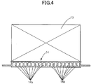
FIG. 4 is a sectional view along line 4-4 inFIG. 3 (first embodiment). -
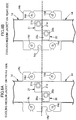
FIGS. 5A and 5B are sectional views alongline 5A-5A inFIG. 3 (first embodiment). -
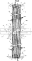
FIG. 6 shows views in the direction of arrow 6 inFIG. 2 (first embodiment). -
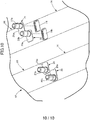
FIG. 7 is a perspective view ofpart 7 inFIG. 2 (first embodiment). -
FIGS. 8A and 8B are diagrams showing the shape of a cutout of a mounting part of a cooling medium jacket (first embodiment). -
FIG. 9 is a diagram corresponding toFIG. 3 (second embodiment). -
FIG. 10 is a diagram corresponding toFIG. 7 (third embodiment). - Embodiments of the present invention are explained below by reference to
FIG. 1 to FIGS. 8A and8B . The fore-and-aft direction, the left-and-right direction (vehicle width direction), and the up-and-down direction in the Specification are on the basis of a vehicle body. - As shown in
FIG. 1 , abattery pack 11 mounted under a floor of a vehicle compartment of an electric vehicle includes a tray-shaped battery case 12, and twelvebattery modules 13 are housed in the interior of thebattery case 12. Eachbattery module 13, which has a rectangular parallelepiped shape, is formed by layering a plurality of battery cells and fastening them as a unit, and six of thebattery modules 13 on each of the left and the right are disposed to form two lines that are symmetrical with respect to the center line of thebattery case 12. An opening in an upper face of thebattery case 12 is covered by a cover, which is not illustrated. - As shown in
FIG. 2 , twelvecooling medium jackets 14 for cooling thebattery modules 13 are disposed on a bottom wall of thebattery case 12 side by side as two, that is, left and right, lines with their longitudinal direction along the vehicle width direction, and onebattery module 13 is disposed on each of thecooling medium jackets 14. A coolingmedium supply piping 15 and a coolingmedium discharge piping 16 are disposed in parallel with each other along the center line of thebattery case 12, and an inner end part in the vehicle width direction of thecooling medium jacket 14 is connected to the coolingmedium supply piping 15 and the coolingmedium discharge piping 16. The six pairs ofcooling medium jackets 14 have a basically identical structure apart from the details, and the structure of one thereof is explained below as an example. - As shown in
FIG. 3 to FIG. 7 , the pair of left and rightcooling medium jackets 14 are formed as a unit; 18 cooling medium passages are formed in parallel with each other along the vehicle width direction in the interior of a main body part formed from a rectangular metal plate, nine thereof on the front side are coolingmedium supply passages 14a, and nine thereof on the rear side are coolingmedium discharge passages 14b. A plate-shaped mounting portion 14c protrudes in the fore-and-aft direction from a middle part in the vehicle width direction of thecooling medium jackets 14, twomounting holes 14d are formed in each of front and rear sides of themounting portion 14c (seeFIG. 7 ), and oneU-shaped cutout 14e is formed in one of the front and rear sides of themounting portion 14c. Furthermore, a plate-shaped mounting portion 14f protrudes in the fore-and-aft direction from an outer end part in the vehicle width direction of thecooling medium jackets 14, and twomounting holes 14g are formed in themounting portion 14f (seeFIG. 6 ). - A plurality of
stud bolts 17 are provided on the bottom wall of thebattery case 12 so as to project upward, and fitting thesestud bolts 17 into themounting holes cooling medium jackets 14 and fastening withnuts 18 fixes thecooling medium jackets 14 to the bottom wall of thebattery case 12. In this process, an erroneous assembly-preventingpin 19 projecting upward from the bottom wall of thebattery case 12 is fitted into acutout 14e formed in themounting portion 14c of thecooling medium jackets 14. - Two
elliptical openings cooling medium jackets 14, the opening 14h on the front side communicates with the nine coolingmedium supply passages 14a, and the opening 14i on the rear side communicates with the nine coolingmedium discharge passages 14b. A nipple-shapedcooling medium inlet 20 includes a plate-shaped blocking portion 20a and a tubular linkingportion 20b, and in a state in which the blockingportion 20a is fixed to the peripheral edge of the opening 14h the linkingportion 20b is connected to the coolingmedium supply piping 15. Furthermore, a nipple-shapedcooling medium outlet 21 includes a plate-shaped blocking portion 21a and a tubular linkingportion 21b, and in a state in which the blockingportion 21a is fixed to the peripheral edge of the opening 14i the linkingportion 21b is connected to the coolingmedium discharge piping 16. - An opening 14j is formed in an upper face of an end part in the vehicle width direction of the
cooling medium jacket 14, and the nine coolingmedium supply passages 14a and the nine coolingmedium discharge passages 14b open in the opening 14j. Fixing acover member 22 with an L-shaped cross section so as to cover the opening 14j of thecooling medium jacket 14 defines acommunication chamber 23 between thecooling medium jacket 14 and thecover member 22, and the nine coolingmedium supply passages 14a and the nine coolingmedium discharge passages 14b are made to communicate with each other via thecommunication chamber 23. - Among the six pairs of
cooling medium jackets 14, three pairs ofcooling medium jackets 14 on the upstream side of the cooling medium supply piping 15 (that is, on the front side) and three pairs ofcooling medium jackets 14 on the downstream side of the cooling medium supply piping 15 (that is, on the rear side) have slightly different structures. - As shown in
FIGS. 5A and 5B , an internal diameter d1 of the coolingmedium inlet 20 of the three pairs of coolingmedium jackets 14 on the front side is set to be smaller than an internal diameter d2 of the coolingmedium inlet 20 of the three pairs of coolingmedium jackets 14 on the rear side. Similarly, with regard to the three pairs of coolingmedium jackets 14 on the front side, an internal diameter d1 of the coolingmedium outlet 21 thereof is set to be smaller than an internal diameter d2 of the coolingmedium outlet 21 of the three pairs of coolingmedium jackets 14 on the rear side. Furthermore, as is clear fromFIG. 2 andFIGS. 8A and 8B , with regard to the three pairs of coolingmedium jackets 14 on the front side and the three pairs of coolingmedium jackets 14 on the rear side, the position and the size of thecutouts 14e of the mountingportions 14c in the middle in the vehicle width direction are different. - The pair of cooling
medium jackets 14 can be used with their left and right sides reversed, and in this case the coolingmedium inlet 20 and the coolingmedium outlet 21 are exchanged and the coolingmedium supply passages 14a and the coolingmedium discharge passages 14b are exchanged. In the present embodiment, among the three pairs of coolingmedium jackets 14 on the front side the pair of coolingmedium jacket 14 in the middle in the fore-and-aft direction are flipped horizontally with respect to the other two pairs of coolingmedium jackets 14, and among the three pairs of coolingmedium jackets 14 on the rear side the pair of coolingmedium jacket 14 in the middle in the fore-and-aft direction are flipped horizontally with respect to the other two pairs of coolingmedium jackets 14. - The operation of an embodiment of the present invention having the above arrangement is now explained.
- Cooling medium supplied from the cooling medium supply piping 15 branches from the cooling
medium inlet 20 of the pair of coolingmedium jackets 14 positioned at the frontmost position toward the coolingmedium supply passages 14a on the left and right sides, flows outward in the vehicle width direction, makes a U-turn in thecommunication chambers 23, flows inward in the vehicle width direction in the coolingmedium discharge passages 14b on the left and right sides, is combined in the coolingmedium outlet 21, and is returned to the cooling medium discharge piping 16. In this way, when the left and right coolingmedium jackets 14 are cooled with cooling medium, the left andright battery modules 13 placed on the upper face thereof carry out heat exchange with the coolingmedium jackets 14 and are cooled. Similarly, cooling medium is supplied to the second pair to the sixth pair of coolingmedium jackets 14, and the remainingbattery modules 13 placed on the upper face thereof are cooled. - Since cooling medium is supplied to the cooling
medium supply piping 15, which is disposed in the fore-and-aft direction, from the front to the rear, cooling medium is easily supplied to the coolingmedium jackets 14 connected to the upstream side of the coolingmedium supply piping 15, and it is difficult for cooling medium to be supplied to the coolingmedium jackets 14 connected to the downstream side of the coolingmedium supply piping 15; in the present embodiment, since the internal diameter d1 of the coolingmedium inlets 20 and the coolingmedium outlets 21 of the three pairs of coolingmedium jackets 14 on the upstream side is set to be small, and the internal diameter d2 of the coolingmedium inlets 20 and the coolingmedium outlets 21 of the three pairs of coolingmedium jackets 14 on the downstream side is set to be large, it is possible by making the amount of cooling medium supplied to the six pairs of coolingmedium jackets 14 uniform to evenly cool all of thebattery modules 13. - Furthermore, since the temperature of cooling medium flowing through the interior of each cooling
medium jacket 14 is the lowest at the coolingmedium inlet 20, gradually increases as a result of heat exchange with thebattery module 13 while cooling medium flows through the coolingmedium supply passages 14a and the coolingmedium discharge passages 14b, and is the highest at the coolingmedium outlet 21, there is a possibility that the bottom of thebattery module 13 that is in contact with the coolingmedium jacket 14 will be cooled unevenly. - However, in accordance with the present embodiment, since the downstream end of the cooling
medium supply passages 14a makes a U-turn in thecommunication chamber 23 and is connected to the upstream end of the coolingmedium discharge passages 14b, the inner end side in the vehicle width direction of thebattery module 13 is cooled with low temperature cooling medium on the upstream side of the coolingmedium supply passages 14a and high temperature cooling medium on the downstream side of the coolingmedium discharge passages 14b, and the outer end side in the vehicle width direction of thebattery module 13 is cooled with an intermediate temperature cooling medium on the downstream side of the coolingmedium supply passages 14a and an intermediate temperature cooling medium on the upstream side of the coolingmedium discharge passages 14b; as a result, each part in the vehicle width direction of thebattery module 13 can be cooled evenly, thereby preventing a difference in temperature from occurring. - Moreover, since the pair of cooling
medium jackets 14 include the coolingmedium inlet 20 and the coolingmedium outlet 21 in the middle part in the vehicle width direction, and thebattery module 13 on the left side and thebattery module 13 on the right side are cooled with cooling medium supplied and discharged from the coolingmedium inlet 20 and the coolingmedium outlet 21, compared with a case in which each coolingmedium jacket 14 is provided with the coolingmedium inlet 20 and the coolingmedium outlet 21, not only can the structure be simplified, but it is also possible to evenly cool the left andright battery modules 13 by making the flow rate of cooling medium supplied to each of the pair of coolingmedium jackets 14 uniform. - As described above, among the six pairs of cooling
medium jackets 14, since the three pairs of coolingmedium jackets 14 on the front side and the three pairs of coolingmedium jackets 14 on the rear side have different internal diameters for the coolingmedium inlets 20 and the coolingmedium outlets 21, when they are mounted on the bottom wall of thebattery case 12 of thebattery pack 11, there is a possibility that erroneous assembly will occur. - However, in accordance with the present embodiment, as shown in
FIGS. 8A and 8B , since with regard to the three pairs of coolingmedium jackets 14 on the front side and the three pairs of coolingmedium jackets 14 on the rear side the positions of thecutouts 14e provided in the mountingportions 14c are different, if an attempt is made to erroneously assemble the pair of coolingmedium jackets 14 on the front side at the position for the pair of coolingmedium jackets 14 on the rear side or if an attempt is made to erroneously assemble the pair of coolingmedium jackets 14 on the rear side at the position for the pair of coolingmedium jackets 14 on the front side, the erroneous assembly-preventingpin 19 provided on thebattery case 12 will not fit into thecutout 14e, thus making it possible to reliably prevent an erroneous assembly from occurring. - A second embodiment of the present invention is now explained by reference to
FIG. 9 . - In the first embodiment, the downstream end of the cooling
medium supply passages 14a of the coolingmedium jacket 14 and the upstream end of the coolingmedium discharge passages 14b are made to communicate with each other all at once via thecommunication chamber 23 formed in the interior of thecover member 22, but in the second embodiment the downstream end of the coolingmedium supply passages 14a of the coolingmedium jacket 14 and the upstream end of the coolingmedium discharge passages 14b are made to communicate with each other individually via nine linkingpassages 14k formed from a U-shaped groove formed in the interior of thecover member 22. - In accordance with the present embodiment, cooling medium does not form a vortex in the
communication chamber 23, thus enabling the cooling medium to make a smooth U-turn. - A third embodiment of the present invention is now explained by reference to
FIG. 10 . - In the first embodiment, the cooling
medium jackets 14 formed as separate members are mounted on the bottom wall of thebattery case 12 of thebattery pack 11, but in the third embodiment the coolingmedium jackets 14 are formed integrally with the bottom wall of thebattery case 12. - In the present embodiment, it becomes unnecessary to use the
stud bolts 17, the nuts 18, the mountingportions 14c, the mountingportions 14f, etc. for mounting the coolingmedium jackets 14, and not only can the number of components be cut and the structure be simplified, but it is also possible to further cut the number of components and simplify the structure because erroneous assembly does not occur and the erroneous assembly-preventingpins 19 and thecutouts 14e are therefore unnecessary. - Embodiments of the present invention are explained above, but the present invention may be modified in a variety of ways as long as the modifications do not depart from the gist of the present invention.
- For example, the embodiments include the twelve cooling
medium jackets 14, but there may be any number of coolingmedium jackets 14 as long as there are two or more. - Furthermore, in the embodiments there is a large difference in the size of the
cutouts 14e between the three pairs of coolingmedium jackets 14 on the front side and the three pairs of coolingmedium jackets 14 on the rear side, but even when thecutouts 14e have the same size, the function of preventing erroneous assembly is not changed. If the size of thecutouts 14e is different, a worker can differentiate visually between the coolingmedium jackets 14 on the front side and the coolingmedium jackets 14 on the rear side. - In a battery cooling device for an electric vehicle, a cooling medium supply piping and a cooling medium discharge piping are disposed in a fore-and-aft direction in a middle part in a vehicle width direction of a vehicle body. A plurality of cooling members extend toward opposite sides in the vehicle width direction from both the pipings. A cooling medium passage returns in an outer end part in the vehicle width direction of the cooling member. Therefore, when the vehicle is involved in a side collision, it becomes difficult for both the pipings to be damaged, and cooling medium is prevented from leaking. Also, the cooling medium flows by making a U-turn inside the cooling member, thereby enabling positions on outside and inside in the vehicle width direction of a battery to be cooled evenly.
Claims (9)
- A battery cooling device for an electric vehicle comprising
a battery (13) that is for driving the electric vehicle,
a cooling member (14) that has in an interior thereof a cooling medium passage (14a, 14b),
a cooling medium supply piping (15) that supplies cooling medium to the cooling member (14), and
a cooling medium discharge piping (16) that discharges cooling medium from the cooling member (14),
wherein the cooling medium supply piping (15) and the cooling medium discharge piping (16) are disposed in a fore-and-aft direction in a middle part in a vehicle width direction of a vehicle body,
a plurality of cooling members (14) as said cooling member (14) extend toward opposite sides in the vehicle width direction from the cooling medium supply piping (15) and the cooling medium discharge piping (16), and
the cooling medium passage (14a, 14b) returns in an outer end part in the vehicle width direction of the cooling member (14). - The battery cooling device for an electric vehicle according to Claim 1, wherein
two of the cooling members (14), which extend toward opposite sides in the vehicle width direction from the middle part in the vehicle width direction, are formed as a unit, and
the two cooling members (14) comprise a common cooling medium inlet (20) and a common cooling medium outlet (21). - The battery cooling device for an electric vehicle according to Claim 2, wherein with regard to the plurality of cooling members (14) there are two or more types of diameters for the cooling medium inlet (20).
- The battery cooling device for an electric vehicle according to Claim 3, wherein a diameter of the cooling medium inlet (20) connected to an upstream side of the cooling medium supply piping (15) is smaller than a diameter of the cooling medium inlet (20) connected to a downstream side of the cooling medium supply piping (15).
- The battery cooling device for an electric vehicle according to Claim 4, wherein
the cooling member (14) comprises a mounting portion (14c) fixed to a battery case (12), and
the cooling members (14) that have different diameters for the cooling medium inlet (20) have different shapes for the mounting portion (14c). - A battery cooling device for an electric vehicle comprising
a battery (13) that is for driving the electric vehicle,
a battery case (12) that supports the battery (13),
a cooling medium jacket (14) that is formed integrally with the battery case (12) and has a cooling medium passage (14a, 14b) in an interior of the cooling medium jacket (14),
a cooling medium supply piping (15) that supplies cooling medium to the cooling medium jacket (14), and
a cooling medium discharge piping (16) that discharges cooling medium from the cooling medium jacket (14),
wherein the cooling medium supply piping (15) and the cooling medium discharge piping (16) are disposed in a fore-and-aft direction in a middle part in a vehicle width direction of a vehicle body,
a plurality of cooling medium jackets (14) as said cooling medium jacket (14) extend toward opposite sides in the vehicle width direction from the cooling medium supply piping (15) and the cooling medium discharge piping (16), and
the cooling medium passage (14a, 14b) returns in an outer end part in the vehicle width direction of the cooling medium jacket (14). - The battery cooling device for an electric vehicle according to Claim 6, wherein
two of the cooling medium jackets (14), which extend toward opposite sides in the vehicle width direction from the middle part in the vehicle width direction, are formed as a unit, and
the two cooling medium jackets (14) comprise a common cooling medium inlet (20) and a common cooling medium outlet (21). - The battery cooling device for an electric vehicle according to Claim 7, wherein with regard to the plurality of cooling medium jackets (14) there are two or more types of diameters for the cooling medium inlet (20).
- The battery cooling device for an electric vehicle according to Claim 8, wherein a diameter of the cooling medium inlet (20) connected to an upstream side of the cooling medium supply piping (15) is smaller than a diameter of the cooling medium inlet (20) connected to a downstream side of the cooling medium supply piping (15).
Applications Claiming Priority (1)
| Application Number | Priority Date | Filing Date | Title |
|---|---|---|---|
| JP2018078426A JP6683756B2 (en) | 2018-04-16 | 2018-04-16 | Battery cooling device for electric vehicle |
Publications (3)
| Publication Number | Publication Date |
|---|---|
| EP3590748A2 true EP3590748A2 (en) | 2020-01-08 |
| EP3590748A3 EP3590748A3 (en) | 2020-02-12 |
| EP3590748B1 EP3590748B1 (en) | 2021-03-03 |
Family
ID=65995654
Family Applications (1)
| Application Number | Title | Priority Date | Filing Date |
|---|---|---|---|
| EP19165739.4A Active EP3590748B1 (en) | 2018-04-16 | 2019-03-28 | Battery cooling device for electric vehicle |
Country Status (4)
| Country | Link |
|---|---|
| US (1) | US10944137B2 (en) |
| EP (1) | EP3590748B1 (en) |
| JP (1) | JP6683756B2 (en) |
| CN (1) | CN110386032B (en) |
Cited By (2)
| Publication number | Priority date | Publication date | Assignee | Title |
|---|---|---|---|---|
| US11309599B2 (en) | 2019-05-16 | 2022-04-19 | Honda Motor Co., Ltd. | Cooling structure of vehicle battery unit |
| DE102024113696A1 (en) * | 2024-05-16 | 2025-11-20 | Bayerische Motoren Werke Aktiengesellschaft | Method for temperature control of battery cells of a vehicle battery using a temperature control device and motor vehicle |
Families Citing this family (11)
| Publication number | Priority date | Publication date | Assignee | Title |
|---|---|---|---|---|
| JP7652539B2 (en) * | 2020-04-16 | 2025-03-27 | 株式会社ブルーエナジー | Power storage device |
| KR102930876B1 (en) | 2020-04-29 | 2026-02-24 | 주식회사 엘지에너지솔루션 | Battery Pack and Electronic Device Comprising the Same and Vehicle |
| JP2022012796A (en) * | 2020-07-02 | 2022-01-17 | 本田技研工業株式会社 | Battery device and electric vehicle |
| US12485981B2 (en) | 2021-03-24 | 2025-12-02 | Polaris Industries Inc. | Electric recreational vehicle |
| JP2023090309A (en) * | 2021-12-17 | 2023-06-29 | 株式会社ティラド | Misassembly prevention structure for combined parts and heat exchanger having such structure |
| JP7154662B1 (en) | 2022-03-17 | 2022-10-18 | 富士精工株式会社 | battery cooling system |
| US12123664B2 (en) | 2022-10-28 | 2024-10-22 | Valeo Systemes Thermiques | Tank and tube assembly for a heat exchanger |
| WO2024112704A2 (en) * | 2022-11-21 | 2024-05-30 | Tae Technologies, Inc. | Systems, devices, and methods for battery module cooling |
| FR3146197B1 (en) * | 2023-02-27 | 2026-01-23 | Valeo Systemes Thermiques | Thermal regulation device with central manifold |
| JP7612737B2 (en) * | 2023-03-08 | 2025-01-14 | 本田技研工業株式会社 | Battery pack |
| DE102025142499A1 (en) | 2024-11-07 | 2026-05-07 | Isuzu Motors Limited | BATTERY PACK |
Citations (1)
| Publication number | Priority date | Publication date | Assignee | Title |
|---|---|---|---|---|
| JP6064730B2 (en) | 2013-03-26 | 2017-01-25 | 三菱自動車工業株式会社 | Cooling system |
Family Cites Families (22)
| Publication number | Priority date | Publication date | Assignee | Title |
|---|---|---|---|---|
| US4407269A (en) * | 1978-07-07 | 1983-10-04 | Sunsearch, Inc. | Solar energy collector system having balanced heat-exchange fluid flow |
| JP4608641B2 (en) * | 2005-04-27 | 2011-01-12 | 株式会社豊田自動織機 | Power module heat sink |
| DE102010032899A1 (en) * | 2010-07-30 | 2012-02-02 | Valeo Klimasysteme Gmbh | Cooling device for a vehicle battery and vehicle battery assembly with such a cooling device |
| JP5124006B2 (en) * | 2010-11-16 | 2013-01-23 | 本田技研工業株式会社 | Battery cooling structure |
| JP5533640B2 (en) * | 2010-12-24 | 2014-06-25 | トヨタ自動車株式会社 | Battery cooling structure |
| JP2013067335A (en) * | 2011-09-26 | 2013-04-18 | Fuji Heavy Ind Ltd | Cooling structure for in-vehicle battery |
| KR101372096B1 (en) * | 2011-11-18 | 2014-03-07 | 엘지전자 주식회사 | A heat exchanger |
| EP2608309A1 (en) * | 2011-12-21 | 2013-06-26 | Fortu Intellectual Property AG | Battery module with battery module housing and battery cells |
| US9647249B2 (en) * | 2012-01-17 | 2017-05-09 | Ford Global Technologies, Llc | Cooling system for vehicle batteries |
| DE102012005871A1 (en) * | 2012-03-23 | 2013-09-26 | Valeo Klimasysteme Gmbh | Cooling device for a vehicle battery and vehicle battery with cooling device |
| CN202606801U (en) * | 2012-03-29 | 2012-12-19 | 南通华东油压科技有限公司 | Open type master-control hydraulic valve casting sand core |
| CN202871634U (en) * | 2012-09-10 | 2013-04-10 | 乐清市平兴电子有限公司 | A button switch |
| CN202930463U (en) * | 2012-10-29 | 2013-05-08 | 天津力神电池股份有限公司 | 18650 quick serial connection standard module |
| DE102014106954B4 (en) * | 2014-05-16 | 2024-12-24 | Valeo Klimasysteme Gmbh | Device for heating and cooling a battery pack and vehicle drive battery assembly |
| US10263301B2 (en) * | 2015-01-09 | 2019-04-16 | Dana Canada Corporation | Counter-flow heat exchanger for battery thermal management applications |
| JP6513427B2 (en) * | 2015-02-27 | 2019-05-15 | 昭和電工株式会社 | Liquid cooling system |
| DE102015106948A1 (en) * | 2015-05-05 | 2016-11-10 | Dr. Ing. H.C. F. Porsche Aktiengesellschaft | vehicle component |
| DE102015215253A1 (en) * | 2015-08-11 | 2017-02-16 | Bayerische Motoren Werke Aktiengesellschaft | Cooling device for energy storage |
| JPWO2017033412A1 (en) * | 2015-08-27 | 2018-06-14 | 三洋電機株式会社 | Battery system and electric vehicle equipped with battery system |
| CN206124686U (en) * | 2016-09-23 | 2017-04-26 | 法雷奥汽车空调湖北有限公司 | Wrong structure of error protection of vehicle air conditioner slip air door |
| JP6969978B2 (en) * | 2017-11-02 | 2021-11-24 | 昭和電工株式会社 | Heat transfer device |
| DE102018205962A1 (en) * | 2018-04-19 | 2019-10-24 | Dr. Ing. H.C. F. Porsche Aktiengesellschaft | Traction battery for an electrically or partially electrically driven vehicle |
-
2018
- 2018-04-16 JP JP2018078426A patent/JP6683756B2/en active Active
-
2019
- 2019-03-28 EP EP19165739.4A patent/EP3590748B1/en active Active
- 2019-04-04 CN CN201910274420.1A patent/CN110386032B/en active Active
- 2019-04-15 US US16/384,226 patent/US10944137B2/en active Active
Patent Citations (1)
| Publication number | Priority date | Publication date | Assignee | Title |
|---|---|---|---|---|
| JP6064730B2 (en) | 2013-03-26 | 2017-01-25 | 三菱自動車工業株式会社 | Cooling system |
Cited By (2)
| Publication number | Priority date | Publication date | Assignee | Title |
|---|---|---|---|---|
| US11309599B2 (en) | 2019-05-16 | 2022-04-19 | Honda Motor Co., Ltd. | Cooling structure of vehicle battery unit |
| DE102024113696A1 (en) * | 2024-05-16 | 2025-11-20 | Bayerische Motoren Werke Aktiengesellschaft | Method for temperature control of battery cells of a vehicle battery using a temperature control device and motor vehicle |
Also Published As
| Publication number | Publication date |
|---|---|
| US10944137B2 (en) | 2021-03-09 |
| EP3590748B1 (en) | 2021-03-03 |
| US20190319319A1 (en) | 2019-10-17 |
| JP2019186149A (en) | 2019-10-24 |
| EP3590748A3 (en) | 2020-02-12 |
| JP6683756B2 (en) | 2020-04-22 |
| CN110386032B (en) | 2023-05-23 |
| CN110386032A (en) | 2019-10-29 |
Similar Documents
| Publication | Publication Date | Title |
|---|---|---|
| EP3590748B1 (en) | Battery cooling device for electric vehicle | |
| KR102740288B1 (en) | Battery pack housing and battery pack including the same | |
| JP6543604B2 (en) | vehicle | |
| US10476117B2 (en) | Vehicle power supply system | |
| US10734693B2 (en) | Cell module for electric and hybrid vehicles | |
| KR20220019000A (en) | Direct Cooling Battery Pack | |
| JP2010503976A (en) | Modular battery device | |
| EP4421950B1 (en) | BATTERY PACK | |
| JP7209219B2 (en) | Cooling device and enclosure | |
| CN114303276B (en) | Heat Exchanger | |
| KR20220105840A (en) | Battery cooling apparatus | |
| KR20250004275A (en) | Battery boxes, batteries and electrical devices | |
| JP7423232B2 (en) | Cooler for vehicle battery case | |
| CN119050543A (en) | Battery module | |
| US20250158207A1 (en) | Housing | |
| KR20250084685A (en) | Battery housing | |
| JP2024046107A (en) | battery case | |
| EP4645529A1 (en) | Battery cooling device | |
| KR20240086171A (en) | High voltage battery module | |
| KR20230130902A (en) | Refrigerant module for vehicle and manufacturing method for same | |
| KR20230103670A (en) | Battery Thermal Management System for Electric Vehicle | |
| CN222655614U (en) | Box, electronic equipment, power assembly and vehicle | |
| KR20200057857A (en) | Cooling device for vehicle | |
| KR102926765B1 (en) | Integrated water supply module | |
| US12374735B2 (en) | Temperature control apparatus |
Legal Events
| Date | Code | Title | Description |
|---|---|---|---|
| PUAI | Public reference made under article 153(3) epc to a published international application that has entered the european phase |
Free format text: ORIGINAL CODE: 0009012 |
|
| STAA | Information on the status of an ep patent application or granted ep patent |
Free format text: STATUS: REQUEST FOR EXAMINATION WAS MADE |
|
| 17P | Request for examination filed |
Effective date: 20190328 |
|
| AK | Designated contracting states |
Kind code of ref document: A2 Designated state(s): AL AT BE BG CH CY CZ DE DK EE ES FI FR GB GR HR HU IE IS IT LI LT LU LV MC MK MT NL NO PL PT RO RS SE SI SK SM TR |
|
| AX | Request for extension of the european patent |
Extension state: BA ME |
|
| PUAL | Search report despatched |
Free format text: ORIGINAL CODE: 0009013 |
|
| AK | Designated contracting states |
Kind code of ref document: A3 Designated state(s): AL AT BE BG CH CY CZ DE DK EE ES FI FR GB GR HR HU IE IS IT LI LT LU LV MC MK MT NL NO PL PT RO RS SE SI SK SM TR |
|
| AX | Request for extension of the european patent |
Extension state: BA ME |
|
| RIC1 | Information provided on ipc code assigned before grant |
Ipc: B60K 1/04 20190101ALI20200109BHEP Ipc: B60K 1/00 20060101AFI20200109BHEP Ipc: H01M 10/625 20140101ALI20200109BHEP Ipc: F28F 3/12 20060101ALI20200109BHEP Ipc: H01M 10/613 20140101ALI20200109BHEP Ipc: H01M 10/617 20140101ALI20200109BHEP |
|
| GRAP | Despatch of communication of intention to grant a patent |
Free format text: ORIGINAL CODE: EPIDOSNIGR1 |
|
| STAA | Information on the status of an ep patent application or granted ep patent |
Free format text: STATUS: GRANT OF PATENT IS INTENDED |
|
| INTG | Intention to grant announced |
Effective date: 20201113 |
|
| GRAS | Grant fee paid |
Free format text: ORIGINAL CODE: EPIDOSNIGR3 |
|
| GRAA | (expected) grant |
Free format text: ORIGINAL CODE: 0009210 |
|
| STAA | Information on the status of an ep patent application or granted ep patent |
Free format text: STATUS: THE PATENT HAS BEEN GRANTED |
|
| AK | Designated contracting states |
Kind code of ref document: B1 Designated state(s): AL AT BE BG CH CY CZ DE DK EE ES FI FR GB GR HR HU IE IS IT LI LT LU LV MC MK MT NL NO PL PT RO RS SE SI SK SM TR |
|
| REG | Reference to a national code |
Ref country code: GB Ref legal event code: FG4D |
|
| REG | Reference to a national code |
Ref country code: CH Ref legal event code: EP Ref country code: AT Ref legal event code: REF Ref document number: 1366826 Country of ref document: AT Kind code of ref document: T Effective date: 20210315 |
|
| REG | Reference to a national code |
Ref country code: DE Ref legal event code: R096 Ref document number: 602019002853 Country of ref document: DE |
|
| REG | Reference to a national code |
Ref country code: IE Ref legal event code: FG4D |
|
| REG | Reference to a national code |
Ref country code: LT Ref legal event code: MG9D |
|
| PG25 | Lapsed in a contracting state [announced via postgrant information from national office to epo] |
Ref country code: NO Free format text: LAPSE BECAUSE OF FAILURE TO SUBMIT A TRANSLATION OF THE DESCRIPTION OR TO PAY THE FEE WITHIN THE PRESCRIBED TIME-LIMIT Effective date: 20210603 Ref country code: LT Free format text: LAPSE BECAUSE OF FAILURE TO SUBMIT A TRANSLATION OF THE DESCRIPTION OR TO PAY THE FEE WITHIN THE PRESCRIBED TIME-LIMIT Effective date: 20210303 Ref country code: GR Free format text: LAPSE BECAUSE OF FAILURE TO SUBMIT A TRANSLATION OF THE DESCRIPTION OR TO PAY THE FEE WITHIN THE PRESCRIBED TIME-LIMIT Effective date: 20210604 Ref country code: FI Free format text: LAPSE BECAUSE OF FAILURE TO SUBMIT A TRANSLATION OF THE DESCRIPTION OR TO PAY THE FEE WITHIN THE PRESCRIBED TIME-LIMIT Effective date: 20210303 Ref country code: HR Free format text: LAPSE BECAUSE OF FAILURE TO SUBMIT A TRANSLATION OF THE DESCRIPTION OR TO PAY THE FEE WITHIN THE PRESCRIBED TIME-LIMIT Effective date: 20210303 Ref country code: BG Free format text: LAPSE BECAUSE OF FAILURE TO SUBMIT A TRANSLATION OF THE DESCRIPTION OR TO PAY THE FEE WITHIN THE PRESCRIBED TIME-LIMIT Effective date: 20210603 |
|
| REG | Reference to a national code |
Ref country code: NL Ref legal event code: MP Effective date: 20210303 |
|
| REG | Reference to a national code |
Ref country code: AT Ref legal event code: MK05 Ref document number: 1366826 Country of ref document: AT Kind code of ref document: T Effective date: 20210303 |
|
| PG25 | Lapsed in a contracting state [announced via postgrant information from national office to epo] |
Ref country code: LV Free format text: LAPSE BECAUSE OF FAILURE TO SUBMIT A TRANSLATION OF THE DESCRIPTION OR TO PAY THE FEE WITHIN THE PRESCRIBED TIME-LIMIT Effective date: 20210303 Ref country code: RS Free format text: LAPSE BECAUSE OF FAILURE TO SUBMIT A TRANSLATION OF THE DESCRIPTION OR TO PAY THE FEE WITHIN THE PRESCRIBED TIME-LIMIT Effective date: 20210303 Ref country code: PL Free format text: LAPSE BECAUSE OF FAILURE TO SUBMIT A TRANSLATION OF THE DESCRIPTION OR TO PAY THE FEE WITHIN THE PRESCRIBED TIME-LIMIT Effective date: 20210303 Ref country code: SE Free format text: LAPSE BECAUSE OF FAILURE TO SUBMIT A TRANSLATION OF THE DESCRIPTION OR TO PAY THE FEE WITHIN THE PRESCRIBED TIME-LIMIT Effective date: 20210303 |
|
| PG25 | Lapsed in a contracting state [announced via postgrant information from national office to epo] |
Ref country code: NL Free format text: LAPSE BECAUSE OF FAILURE TO SUBMIT A TRANSLATION OF THE DESCRIPTION OR TO PAY THE FEE WITHIN THE PRESCRIBED TIME-LIMIT Effective date: 20210303 |
|
| PG25 | Lapsed in a contracting state [announced via postgrant information from national office to epo] |
Ref country code: SM Free format text: LAPSE BECAUSE OF FAILURE TO SUBMIT A TRANSLATION OF THE DESCRIPTION OR TO PAY THE FEE WITHIN THE PRESCRIBED TIME-LIMIT Effective date: 20210303 Ref country code: AT Free format text: LAPSE BECAUSE OF FAILURE TO SUBMIT A TRANSLATION OF THE DESCRIPTION OR TO PAY THE FEE WITHIN THE PRESCRIBED TIME-LIMIT Effective date: 20210303 Ref country code: CZ Free format text: LAPSE BECAUSE OF FAILURE TO SUBMIT A TRANSLATION OF THE DESCRIPTION OR TO PAY THE FEE WITHIN THE PRESCRIBED TIME-LIMIT Effective date: 20210303 Ref country code: EE Free format text: LAPSE BECAUSE OF FAILURE TO SUBMIT A TRANSLATION OF THE DESCRIPTION OR TO PAY THE FEE WITHIN THE PRESCRIBED TIME-LIMIT Effective date: 20210303 |
|
| PG25 | Lapsed in a contracting state [announced via postgrant information from national office to epo] |
Ref country code: IS Free format text: LAPSE BECAUSE OF FAILURE TO SUBMIT A TRANSLATION OF THE DESCRIPTION OR TO PAY THE FEE WITHIN THE PRESCRIBED TIME-LIMIT Effective date: 20210703 Ref country code: RO Free format text: LAPSE BECAUSE OF FAILURE TO SUBMIT A TRANSLATION OF THE DESCRIPTION OR TO PAY THE FEE WITHIN THE PRESCRIBED TIME-LIMIT Effective date: 20210303 Ref country code: PT Free format text: LAPSE BECAUSE OF FAILURE TO SUBMIT A TRANSLATION OF THE DESCRIPTION OR TO PAY THE FEE WITHIN THE PRESCRIBED TIME-LIMIT Effective date: 20210705 Ref country code: SK Free format text: LAPSE BECAUSE OF FAILURE TO SUBMIT A TRANSLATION OF THE DESCRIPTION OR TO PAY THE FEE WITHIN THE PRESCRIBED TIME-LIMIT Effective date: 20210303 |
|
| REG | Reference to a national code |
Ref country code: DE Ref legal event code: R097 Ref document number: 602019002853 Country of ref document: DE |
|
| REG | Reference to a national code |
Ref country code: BE Ref legal event code: MM Effective date: 20210331 |
|
| PLBE | No opposition filed within time limit |
Free format text: ORIGINAL CODE: 0009261 |
|
| STAA | Information on the status of an ep patent application or granted ep patent |
Free format text: STATUS: NO OPPOSITION FILED WITHIN TIME LIMIT |
|
| PG25 | Lapsed in a contracting state [announced via postgrant information from national office to epo] |
Ref country code: FR Free format text: LAPSE BECAUSE OF NON-PAYMENT OF DUE FEES Effective date: 20210503 Ref country code: MC Free format text: LAPSE BECAUSE OF FAILURE TO SUBMIT A TRANSLATION OF THE DESCRIPTION OR TO PAY THE FEE WITHIN THE PRESCRIBED TIME-LIMIT Effective date: 20210303 Ref country code: AL Free format text: LAPSE BECAUSE OF FAILURE TO SUBMIT A TRANSLATION OF THE DESCRIPTION OR TO PAY THE FEE WITHIN THE PRESCRIBED TIME-LIMIT Effective date: 20210303 Ref country code: DK Free format text: LAPSE BECAUSE OF FAILURE TO SUBMIT A TRANSLATION OF THE DESCRIPTION OR TO PAY THE FEE WITHIN THE PRESCRIBED TIME-LIMIT Effective date: 20210303 Ref country code: LU Free format text: LAPSE BECAUSE OF NON-PAYMENT OF DUE FEES Effective date: 20210328 Ref country code: IE Free format text: LAPSE BECAUSE OF NON-PAYMENT OF DUE FEES Effective date: 20210328 Ref country code: ES Free format text: LAPSE BECAUSE OF FAILURE TO SUBMIT A TRANSLATION OF THE DESCRIPTION OR TO PAY THE FEE WITHIN THE PRESCRIBED TIME-LIMIT Effective date: 20210303 |
|
| 26N | No opposition filed |
Effective date: 20211206 |
|
| PG25 | Lapsed in a contracting state [announced via postgrant information from national office to epo] |
Ref country code: SI Free format text: LAPSE BECAUSE OF FAILURE TO SUBMIT A TRANSLATION OF THE DESCRIPTION OR TO PAY THE FEE WITHIN THE PRESCRIBED TIME-LIMIT Effective date: 20210303 |
|
| PG25 | Lapsed in a contracting state [announced via postgrant information from national office to epo] |
Ref country code: IT Free format text: LAPSE BECAUSE OF FAILURE TO SUBMIT A TRANSLATION OF THE DESCRIPTION OR TO PAY THE FEE WITHIN THE PRESCRIBED TIME-LIMIT Effective date: 20210303 |
|
| PG25 | Lapsed in a contracting state [announced via postgrant information from national office to epo] |
Ref country code: IS Free format text: LAPSE BECAUSE OF FAILURE TO SUBMIT A TRANSLATION OF THE DESCRIPTION OR TO PAY THE FEE WITHIN THE PRESCRIBED TIME-LIMIT Effective date: 20210703 |
|
| PG25 | Lapsed in a contracting state [announced via postgrant information from national office to epo] |
Ref country code: BE Free format text: LAPSE BECAUSE OF NON-PAYMENT OF DUE FEES Effective date: 20210331 |
|
| REG | Reference to a national code |
Ref country code: DE Ref legal event code: R084 Ref document number: 602019002853 Country of ref document: DE |
|
| REG | Reference to a national code |
Ref country code: CH Ref legal event code: PL |
|
| PG25 | Lapsed in a contracting state [announced via postgrant information from national office to epo] |
Ref country code: LI Free format text: LAPSE BECAUSE OF NON-PAYMENT OF DUE FEES Effective date: 20220331 Ref country code: CH Free format text: LAPSE BECAUSE OF NON-PAYMENT OF DUE FEES Effective date: 20220331 |
|
| PG25 | Lapsed in a contracting state [announced via postgrant information from national office to epo] |
Ref country code: CY Free format text: LAPSE BECAUSE OF FAILURE TO SUBMIT A TRANSLATION OF THE DESCRIPTION OR TO PAY THE FEE WITHIN THE PRESCRIBED TIME-LIMIT Effective date: 20210303 |
|
| PG25 | Lapsed in a contracting state [announced via postgrant information from national office to epo] |
Ref country code: HU Free format text: LAPSE BECAUSE OF FAILURE TO SUBMIT A TRANSLATION OF THE DESCRIPTION OR TO PAY THE FEE WITHIN THE PRESCRIBED TIME-LIMIT; INVALID AB INITIO Effective date: 20190328 |
|
| GBPC | Gb: european patent ceased through non-payment of renewal fee |
Effective date: 20230328 |
|
| PG25 | Lapsed in a contracting state [announced via postgrant information from national office to epo] |
Ref country code: GB Free format text: LAPSE BECAUSE OF NON-PAYMENT OF DUE FEES Effective date: 20230328 |
|
| PG25 | Lapsed in a contracting state [announced via postgrant information from national office to epo] |
Ref country code: GB Free format text: LAPSE BECAUSE OF NON-PAYMENT OF DUE FEES Effective date: 20230328 |
|
| PG25 | Lapsed in a contracting state [announced via postgrant information from national office to epo] |
Ref country code: MK Free format text: LAPSE BECAUSE OF FAILURE TO SUBMIT A TRANSLATION OF THE DESCRIPTION OR TO PAY THE FEE WITHIN THE PRESCRIBED TIME-LIMIT Effective date: 20210303 |
|
| PG25 | Lapsed in a contracting state [announced via postgrant information from national office to epo] |
Ref country code: TR Free format text: LAPSE BECAUSE OF FAILURE TO SUBMIT A TRANSLATION OF THE DESCRIPTION OR TO PAY THE FEE WITHIN THE PRESCRIBED TIME-LIMIT Effective date: 20210303 |
|
| PG25 | Lapsed in a contracting state [announced via postgrant information from national office to epo] |
Ref country code: MT Free format text: LAPSE BECAUSE OF FAILURE TO SUBMIT A TRANSLATION OF THE DESCRIPTION OR TO PAY THE FEE WITHIN THE PRESCRIBED TIME-LIMIT Effective date: 20210303 |
|
| PGFP | Annual fee paid to national office [announced via postgrant information from national office to epo] |
Ref country code: DE Payment date: 20260219 Year of fee payment: 8 |