EP3590729A1 - Ensemble de roue avec broches d'alignement - Google Patents
Ensemble de roue avec broches d'alignement Download PDFInfo
- Publication number
- EP3590729A1 EP3590729A1 EP19155033.4A EP19155033A EP3590729A1 EP 3590729 A1 EP3590729 A1 EP 3590729A1 EP 19155033 A EP19155033 A EP 19155033A EP 3590729 A1 EP3590729 A1 EP 3590729A1
- Authority
- EP
- European Patent Office
- Prior art keywords
- alignment pin
- outboard
- wheel half
- opening
- inboard
- Prior art date
- Legal status (The legal status is an assumption and is not a legal conclusion. Google has not performed a legal analysis and makes no representation as to the accuracy of the status listed.)
- Withdrawn
Links
- 230000004323 axial length Effects 0.000 claims description 20
- 230000008878 coupling Effects 0.000 claims description 2
- 238000010168 coupling process Methods 0.000 claims description 2
- 238000005859 coupling reaction Methods 0.000 claims description 2
- 238000000034 method Methods 0.000 description 9
- 230000008901 benefit Effects 0.000 description 6
- 230000000712 assembly Effects 0.000 description 4
- 238000000429 assembly Methods 0.000 description 4
- 230000006978 adaptation Effects 0.000 description 1
- 238000010276 construction Methods 0.000 description 1
- 238000005260 corrosion Methods 0.000 description 1
- 230000007797 corrosion Effects 0.000 description 1
- 230000012447 hatching Effects 0.000 description 1
Images


Classifications
-
- B—PERFORMING OPERATIONS; TRANSPORTING
- B60—VEHICLES IN GENERAL
- B60B—VEHICLE WHEELS; CASTORS; AXLES FOR WHEELS OR CASTORS; INCREASING WHEEL ADHESION
- B60B25/00—Rims built-up of several main parts ; Locking means for the rim parts
- B60B25/002—Rims split in circumferential direction
- B60B25/004—Rims split in circumferential direction one rim part comprising the wheel disc
-
- B—PERFORMING OPERATIONS; TRANSPORTING
- B60—VEHICLES IN GENERAL
- B60B—VEHICLE WHEELS; CASTORS; AXLES FOR WHEELS OR CASTORS; INCREASING WHEEL ADHESION
- B60B23/00—Attaching rim to wheel body
- B60B23/06—Attaching rim to wheel body by screws, bolts, pins, or clips
- B60B23/10—Attaching rim to wheel body by screws, bolts, pins, or clips arranged axially
-
- B—PERFORMING OPERATIONS; TRANSPORTING
- B60—VEHICLES IN GENERAL
- B60B—VEHICLE WHEELS; CASTORS; AXLES FOR WHEELS OR CASTORS; INCREASING WHEEL ADHESION
- B60B3/00—Disc wheels, i.e. wheels with load-supporting disc body
- B60B3/04—Disc wheels, i.e. wheels with load-supporting disc body with a single disc body not integral with rim, i.e. disc body and rim being manufactured independently and then permanently attached to each other in a second step, e.g. by welding
- B60B3/041—Disc wheels, i.e. wheels with load-supporting disc body with a single disc body not integral with rim, i.e. disc body and rim being manufactured independently and then permanently attached to each other in a second step, e.g. by welding characterised by the attachment of rim to wheel disc
-
- B—PERFORMING OPERATIONS; TRANSPORTING
- B64—AIRCRAFT; AVIATION; COSMONAUTICS
- B64C—AEROPLANES; HELICOPTERS
- B64C25/00—Alighting gear
- B64C25/32—Alighting gear characterised by elements which contact the ground or similar surface
- B64C25/34—Alighting gear characterised by elements which contact the ground or similar surface wheeled type, e.g. multi-wheeled bogies
- B64C25/36—Arrangements or adaptations of wheels, tyres or axles in general
-
- B—PERFORMING OPERATIONS; TRANSPORTING
- B60—VEHICLES IN GENERAL
- B60B—VEHICLE WHEELS; CASTORS; AXLES FOR WHEELS OR CASTORS; INCREASING WHEEL ADHESION
- B60B2320/00—Manufacturing or maintenance operations
- B60B2320/10—Assembling; disassembling
- B60B2320/14—Assembly devices for divided rims
-
- B—PERFORMING OPERATIONS; TRANSPORTING
- B60—VEHICLES IN GENERAL
- B60B—VEHICLE WHEELS; CASTORS; AXLES FOR WHEELS OR CASTORS; INCREASING WHEEL ADHESION
- B60B2900/00—Purpose of invention
- B60B2900/50—Improvement of
- B60B2900/541—Servicing
-
- B—PERFORMING OPERATIONS; TRANSPORTING
- B60—VEHICLES IN GENERAL
- B60Y—INDEXING SCHEME RELATING TO ASPECTS CROSS-CUTTING VEHICLE TECHNOLOGY
- B60Y2200/00—Type of vehicle
- B60Y2200/50—Aeroplanes, Helicopters
- B60Y2200/51—Aeroplanes
Definitions
- the present disclosure relates to aircraft wheel assemblies and, in particular, to a wheel assembly having an alignment pin.
- Aircraft typically include landing gear for supporting the aircraft above a ground surface and for allowing the aircraft to move relative to the ground surface while remaining supported by the ground surface.
- the landing gear may include one or more split wheel assemblies having an inboard portion and an outboard portion, which define a tubewell.
- the outboard portion may be secured to the inboard portion via a plurality of bolted joints (e.g., nuts engaging bolts). Loosening of one or more of the bolted joints can result in a rupture of the tubewell. Bolted joints tend to be more prone to loosen when lateral loads are applied to the joint after it is tightened. Movement of the wheel assembly outboard and inboard portions relative to one another can generate these lateral loads. Accordingly, it may be desirable to restrict movement of outboard and inboard portions relative to one another.
- the wheel assembly may comprise an inboard wheel half including a flange.
- the flange may define a first alignment pin opening.
- An outboard wheel half may define a second alignment pin opening.
- the first alignment pin opening and the second alignment pin opening define a volume configured to receive an alignment pin.
- the alignment pin may be located in the first alignment pin opening and the second alignment pin opening. In various embodiments, an axial length of the alignment pin may be between 45% and 80% of an axial length extending from an inboard surface of the flange to an outboard surface of the outboard wheel half.
- a first end of the alignment pin may be press fit into at least one of the flange or the outboard wheel half.
- a second end of the alignment pin opposite the first end of the alignment pin may be slip fit into at least one of the flange or the outboard wheel half.
- a torque bar may be coupled to the inboard wheel half. An end of the torque bar may be located in the first alignment pin opening.
- at least one of the first alignment pin opening or the second alignment pin opening may be a blind alignment pin opening.
- at least one of the first alignment pin opening or the second alignment pin opening may be a stepped alignment pin opening.
- a fastener may couple the inboard wheel half to the outboard wheel half.
- the fastener may comprise a bolt extending through the flange and the outboard wheel half, and a nut engaging the bolt.
- a wheel assembly for an aircraft may comprise an inboard wheel half including a flange.
- the flange may define a first alignment pin opening.
- An outboard wheel half may define a second alignment pin opening.
- An alignment pin may be located in the first alignment pin opening and the second alignment pin opening.
- An axial length of the alignment pin may be equal to or less than an axial length extending from an inboard surface of the flange to an outboard surface of the outboard wheel half
- a fastener may be located through the flange and the outboard wheel half.
- the first alignment pin opening may extend from the inboard surface of the flange to an outboard surface of the flange opposite the inboard surface of the flange. In various embodiments, at least one of the first alignment pin opening or the second alignment pin opening may be a blind alignment pin opening. In various embodiments, at least one of the first alignment pin opening or the second alignment pin opening may be a stepped alignment pin opening.
- a torque bar may be coupled to the inboard wheel half.
- the alignment pin may be axially aligned with the torque bar.
- the fastener comprises a bolt and a nut engaging the bold.
- a wheel assembly for an aircraft may comprise at least one of an inboard wheel half or an outboard wheel half.
- An alignment pin opening may be defined by the at least one of the inboard wheel half or the outboard wheel half.
- a first fastener opening may be circumferentially adjacent to the alignment pin opening and defined by the at least one of the inboard wheel half or the outboard wheel half.
- a second fastener opening may be circumferentially adjacent to the first fastener opening and defined by the at least one of the inboard wheel half or the outboard wheel half.
- a circumferential distance between the alignment pin opening the first fastener opening may be less than a circumferential distance between the first fastener opening and the second fastener opening.
- the alignment pin opening may be at least one of a blind alignment pin opening or a stepped alignment pin opening.
- an alignment pin may be press fit into the at least one of the inboard wheel half or the outboard wheel half.
- the wheel assembly may further comprise a torque bar. An end of the torque bar may be located within the alignment pin opening.
- a first component that is "radially outward" of a second component means that the first component is positioned at a greater distance away from a common axis than the second component.
- a first component that is “radially inward” of a second component means that the first component is positioned closer to the common axis than the second component.
- a first component that is radially inward of a second component rotates through a circumferentially shorter path than the second component.
- distal refers to the direction outward, or generally, away from a reference component.
- proximal and/or “proximate” refer(s) to a direction inward, or generally, towards the reference component.
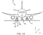
- an aircraft 100 in accordance with various embodiments can include multiple landing gear including a first landing gear 110, a second landing gear 120 and a third landing gear 130.
- Each landing gear may include one or more wheel assemblies.
- third landing gear 130 includes an inner wheel assembly 132 and an outer wheel assembly 134.
- Each wheel assembly of the aircraft 100 may be designed to receive a tire.
- a tire 136 may be placed about an outer circumference of inner wheel assembly 132 and inflated.
- An A-R-C axis is shown in various drawings to illustrate the axial, radial and circumferential directions relative to inner wheel assembly 132.
- the A, or axial, direction corresponds to an axis of rotation of inner wheel assembly 132.
- the R, or radial, direction corresponds to a direction of a radius of inner wheel assembly 132.
- the C, or circumferential, direction corresponds to a direction of the circumference of inner wheel assembly 132.
- inner wheel assembly 132 includes an inboard wheel half 200 and an outboard wheel half 202.
- inner wheel assembly 132 is utilized in an aircraft, one skilled in the art will realize that a similar wheel assembly may be used in other vehicles such as cars or motorcycles.
- FIGs. 1A and 1B describe features of inner wheel assembly 132 of third landing gear 130, it should be understood that outer wheel assembly 134 and/or the wheel assemblies of first landing gear 110 and second landing gear 120 may include the elements and functionalities as described herein with respect to inner wheel assembly 132.
- Inner wheel assembly 132 also includes a tubewell 204.
- Tubewell 204 is defined by inboard wheel half 200 and outboard wheel half 202.
- Tubewell 204 may receive tire 136, with momentary reference to FIG. 1A , and may form a seal with tire 136 to allow pressurized air to inflate the tire.
- inboard wheel half 200 includes a radially outward extending lip or rim 210 and a radially inward extending lip or flange 212.
- Rim 210 is located at an inboard end of inboard wheel half 200.
- Flange 212 is located at an outboard end of inboard wheel half 200.
- rim 210 is distal to outboard wheel half 202, and flange 212 is proximate to outboard wheel half 202.
- a plurality of torque bars 215 may be located circumferentially along a radially inward surface 217 of inboard wheel half 200. Torque bars 215 may extend between, and be secured to, flange 212 and the inboard end of inboard wheel half 200.
- Flange 212 includes an inboard surface 214, an outboard surface 216 opposite inboard surface 214, a radially outward surface 218, and a radially inward surface 219 opposite radially outward surface 218.
- a seal 211 for example an O-ring, may be located around radially outward surface 218 and may seal a space between inboard wheel half 200 and outboard wheel half 202.
- fastener openings 220 may each be configured to receive a fastener 224.
- Fastener 224 may be configured to secure outboard wheel half 202 to inboard wheel half 200 and prevent and/or reduce axial movement of the wheel halves relative to one another.
- Alignment pin openings 222 may each be configured to receive an alignment pin 230.
- Alignment pin 230 may be configured to reduce and/or prevent lateral sliding/movement of the wheel halves relative to one another.
- a fastener opening refers to an opening that receives a fastener or other securement mechanism that tends to reduce and/or prevent axial movement of the wheel halves
- a “alignment pin opening” refers to an opening that receives a pin or other structure that tends to reduce and/or prevent lateral movement of the wheel halves and allow axial movement of the wheel halves.
- Alignment pin openings 222 may extend completely through flange 212, such that alignment pin openings 222 extend from inboard surface 214 to outboard surface 216. Alignment pin opening 222 is configured to receive an inboard end 231 of alignment pin 230, with momentary reference to FIG. 2E . In various embodiments, alignment pin opening 222 may be configured (e.g., a diameter of alignment pin opening 222 may be selected) such that alignment pin 230 may be press fit into flange 212. In this regard, frictional force may secure alignment pin 230 to flange 212.
- alignment pin openings 222 may be located circumferentially between fastener openings 220 such that each alignment pin opening 222 has a fastener opening 220a that is circumferentially adjacent in a clockwise direction and a fastener opening 220b that is circumferentially adjacent in a counter clockwise direction. Stated differently, alignment pin opening 222 is circumferentially adjacent to fastener opening 220a and fastener opening 220b. Fastener opening 220a is circumferentially adjacent to alignment pin opening 222 and fastener opening 220c.
- a distance C1 as measured circumferentially, between a center axis of alignment pin opening 222 and a center axis of fastener opening 220a (i.e., a center axis of the fastener opening that is circumferentially adjacent to alignment pin opening 222) is less than a distance C2, as measured circumferentially, between the center axis of fastener opening 220a and a center axis of fastener opening 220c (i.e., a center axis of the fastener opening that is circumferentially adjacent to fastener opening 220a).
- outboard wheel half 202 is illustrated, in accordance with various embodiments.
- outboard wheel half 202 includes a radially outward extending lip or rim 240.
- Rim 240 is located at an outboard end of outboard wheel half 202.
- Outboard wheel half includes an outboard surface 242 and an inboard surface 244 opposite outboard surface 242.
- Inboard surface 244 is oriented toward outboard surface 216 of inboard wheel half 200, with momentary reference to FIG. 2A , when outboard wheel half 202 is secured to inboard wheel half 200.
- Outboard wheel half 202 defines a plurality of fastener openings 250 and a plurality of alignment pin openings 252.
- Fastener openings 222 may be distributed substantially equally along flange 212. As used in this context only, “substantially equally” means that the distances between any two fastener openings 222 are with +/- 5% of one another. Fastener openings 222 may be either distributed symmetrically or asymmetrically about flange 212. Fastener openings 252 may be distributed substantially equally along outboard wheel half 202. As used in this context only, “substantially equally” means that the distances between any two fastener openings 252 are with +/- 5% of one another. Fastener openings 252 may be either distributed symmetrically or asymmetrically about outboard wheel half 202.
- alignment pin openings 252 may be located between fastener openings 250 such that each alignment pin opening 252 has a fastener opening 250a that is circumferentially adjacent in a clockwise direction and a fastener opening 220b that is circumferentially adjacent in a counter clockwise direction. Stated differently, alignment pin opening 252 is circumferentially adjacent to fastener opening 250a and fastener opening 250b. Fastener opening 250a is circumferentially adjacent to alignment pin opening 252 and fastener opening 250c. Fastener opening 250b is circumferentially adjacent to alignment pin opening 252 and fastener opening 250d.
- a distance C3, as measured circumferentially, between a center axis of an alignment pin opening 252 and a center axis of the fastener opening 250 that is circumferentially adjacent to the alignment pin opening 252 may be less than a distance C4, as measured circumferentially, between the center axes of circumferentially adjacent fastener openings (e.g., less than the circumferential distance between fastener opening 250a and fastener opening 250c, or the circumferential distance between fastener opening 250b and fastener opening 250d).
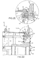
- FIGs. 2D and 2E illustrate a cross-sectional view of a portion of inner wheel assembly 132 with outboard wheel half 202 secured to inboard wheel half 200, in accordance with various embodiments.
- Fastener openings 250 in outboard wheel half 202 are configured to axially align with fastener openings 220 in inboard wheel half 200.
- Fastener openings 220 and 250 receive fastener 224.
- Fastener 224 secures outboard wheel half 202 to inboard wheel half 200.
- fastener 224 includes a bolt 225 extending through flange 212 and outboard wheel half 202, and a nut 226 engaging bolt 225. While fastener 224 is illustrated as including bolt 225 and nut 226, it should be understood that fastener 224 may include a rivet, pin, clip, screw, or any other suitable securement mechanism.
- Alignment pin openings 252 are configured to axially align with alignment pin openings 222 in inboard wheel half 200 and to receive an outboard end 232 of an alignment pin 230.
- alignment pin opening 252 and alignment pin opening 222 together define a volume configured to receive alignment pin 230.
- Alignment pin openings 252 may extend completely through outboard wheel half 202, such that alignment pin openings 252 extend from inboard surface 244 to outboard surface 242.
- alignment pin opening 252 may be configured (e.g., a diameter of alignment pin opening 252 may be selected) such that alignment pin 230 may be slip fit into outboard wheel half 202.
- alignment pin 230 may be in contact with the surface defining alignment pin opening 252, but the frictional force between outboard wheel half 202 and alignment pin 230 may be reduced as compared to the frictional force between flange 212 and alignment pin 230, thereby allowing alignment pin 230 to slide in and out alignment pin opening 252.
- outboard end 232 of alignment pin 230 may be press fit in outboard wheel half 202 and inboard end 231 may be slip fit in flange 212.
- the end of alignment pin 230 that is to be slip fit e.g., outboard end 232 in FIG. 2E
- inner wheel assembly 132 may comprise between two and eight alignment pins 230 spaced circumferentially along flange 212. In various embodiments, inner wheel assembly 132 may comprise between two and six alignment pins 230 spaced circumferentially along flange 212.
- An axial length L1 of alignment pins 230 may be equal to or less than an axial length L2 extending between inboard surface 214 of flange 212 and outboard surface 242 of outboard wheel half 202.
- L1 may be between 30% and 100% of L2.
- L1 may be between 45% and 80% of L2.
- L1 may be between 50% and 80% of L2.
- alignment pin opening 222 comprises a generally consistent diameter D1 and/or cross-sectional area and/or cross-sectional geometry.
- the diameter D1 and/or cross-sectional area and/or cross-sectional geometry of alignment pin opening 222 proximate inboard surface 214 may be equal to the diameter D1 and/or the cross-sectional area and/or the cross-sectional geometry of alignment pin opening 222 proximate outboard surface 216.
- Diameter D1 may be less than, equal to, or greater than a diameter D7 of fastener openings 220, with momentary reference to FIG. 2B .
- Alignment pin opening 252 in outboard wheel half 202 comprises a generally consistent diameter D2 and/or cross-sectional area and/or cross-sectional geometry.
- the diameter D2 and/or cross-sectional area and/or cross-sectional geometry of alignment pin opening 252 proximate inboard surface 244 may be equal to the diameter D2 and/or the cross-section area and/or the cross-sectional geometry of alignment pin opening 252 proximate outboard surface 242.
- Diameter D2 may be less than, equal to, or greater than a diameter D8 of fastener openings 250, with momentary reference to FIG. 2C .
- alignment pins 230 engage inboard wheel half 200 and outboard wheel half 202. Alignment pins 230 engaging both inboard wheel half 200 and outboard wheel half 202 may prevent or reduce lateral sliding/movement of the wheel halves relative to one another. In this regard, alignment pins 230 tend to reduce fastener joint movement and/or a loosening of nuts 226 and bolts 225.
- Wheel assembly 301 includes an inboard wheel half 300 and an outboard wheel half 302 which are similar, respectively, to inboard wheel half 200 and outboard wheel half 202 of inner wheel assembly 132 in FIG. 1B .
- Inboard wheel half 300 includes a radially inward extending flange 312.
- Flange 312 is located at an outboard end of inboard wheel half 300 and proximate to outboard wheel half 302.
- Flange 312 includes an inboard surface 314 and an outboard surface 316 opposite inboard surface 314.
- Flange 312 defines a plurality of fastener openings 320 and a plurality of blind alignment pin openings 322.
- Fastener openings 320 may each be configured to receive a fastener similar to fastener 224 of inner wheel assembly 132 in FIG. 2D (fasteners have been omitted from FIGs. 3A and 3B for the sake of clarity).
- Blind alignment pin openings 322 may extend partially through flange 312, such that a portion of flange 312 remains between an axial surface 324 defining blind alignment pin openings 322 and inboard surface 314 of flange 312.
- Blind alignment pin opening 322 is configured to receive an inboard end 331 of an alignment pin 330.
- blind alignment pin opening 322 may be configured (e.g., a diameter of blind alignment pin opening 322 may be selected) such that alignment pin 330 may be press fit into flange 312. In this regard, frictional force may secure alignment pin 330 to flange 312.
- Outboard wheel half 302 includes an outboard surface 342 and an inboard surface 344 opposite outboard surface 342. Inboard surface 344 is oriented toward outboard surface 316 of inboard wheel half 300, when outboard wheel half 302 is secured to inboard wheel half 300.
- Outboard wheel half 302 defines a plurality of fastener openings (similar to fastener openings 250, in FIG. 2C ) configured to axially align with fastener openings 320 in inboard wheel half 300.
- Outboard wheel half 302 also defines a plurality of blind alignment pin openings 352. Blind alignment pin openings 352 are configured to axially align with blind alignment pin openings 322 in inboard wheel half 300 and to receive an outboard end 332 of an alignment pin 330. In this regard, blind alignment pin opening 352 and blind alignment pin opening 322 together define a volume configured to receive alignment pin 330.
- Blind alignment pin openings 352 may extend partially through outboard wheel half 302, such that a portion of outboard wheel half 302 remains between an axial surface 354 defining blind alignment pin openings 352 and outboard surface 342 of outboard wheel half 302.
- blind alignment pin opening 352 may be configured (e.g., a diameter of blind alignment pin opening 352 may be selected) such that alignment pin 330 may be slip fit into outboard wheel half 302.
- alignment pin 330 may be in contact with the surface defining blind alignment pin opening 352, but the frictional force between outboard wheel half 302 and alignment pin 330 may be reduced as compared to the frictional force between flange 312 and alignment pin 330, thereby allowing alignment pin 330 to slide in and out blind alignment pin opening 352.
- outboard end 332 of alignment pin 330 may be press fit in outboard wheel half 302 and inboard end 331 may be slip fit in flange 312.
- An axial length L3 of alignment pin 330 may be between 30% and 90% of an axial length L4 extending between inboard surface 314 of flange 312 and outboard surface 342 of outboard wheel half 302. In various embodiments, L3 may be between 45% and 80% of L4. In various embodiments, L3 may be between 50% and 80% of L4. In various embodiments, the axial length L3 of alignment pin 330 may be approximately equal to the combined axial length of blind alignment pin opening 322 and blind alignment pin opening 352. As used in this context only, “approximately equal" means length L3 is within 5% of the combined axial length of blind alignment pin opening 322 and blind alignment pin opening 352.
- alignment pins 330 engage inboard wheel half 300 and outboard wheel half 302. Alignment pins 330 engaging both inboard wheel half 300 and outboard wheel half 302 may prevent or reduce lateral sliding/movement of the wheel halves relative to one another. In this regard, alignment pins 330 tend to reduce fastener joint movement and/or a loosening of nuts and bolts.
- Wheel assembly 401 having stepped alignment pin openings is illustrated, in accordance with various embodiments.
- Wheel assembly 401 includes an inboard wheel half 400 and an outboard wheel half 402 which are similar, respectively, to inboard wheel half 200 and outboard wheel half 202 of inner wheel assembly 132 in FIG. 1B .
- Inboard wheel half 400 includes a radially inward extending flange 412.
- Flange 412 is located at an outboard end of inboard wheel half 400 and proximate to outboard wheel half 402.
- Flange 412 includes an inboard surface 414 and an outboard surface 416 opposite inboard surface 414.
- Flange 412 defines a plurality of fastener openings 420 and a plurality of stepped alignment pin openings 422.
- Fastener openings 420 may each be configured to receive a fastener similar to fastener 224 of inner wheel assembly 132 in FIG. 2D (fasteners have been omitted from FIGs. 4A and 4B for the sake of clarity).
- Stepped alignment pin openings 422 may extend completely through flange 412, such that stepped alignment pin openings 422 extend from inboard surface 414 to outboard surface 416 of flange 412.
- first portion 421 of stepped alignment pin opening 422 may be configured (e.g., diameter D3 may be selected) such that alignment pin 430 may be press fit into flange 412. In this regard, frictional force may secure alignment pin 430 to flange 412.
- the diameter D4 of second portion 424 may be less than a diameter of alignment pin 430.
- Outboard wheel half 402 includes an outboard surface 442 and an inboard surface 444 opposite outboard surface 442. Inboard surface 444 is oriented toward outboard surface 416 of inboard wheel half 400, when outboard wheel half 402 is secured to inboard wheel half 400.
- Outboard wheel half 402 defines a plurality of fastener openings (similar to fastener openings 250 in FIG. 2C ) configured to axially align with fastener openings 420 in inboard wheel half 400.
- Outboard wheel half 402 also defines a plurality of stepped alignment pin openings 452. Stepped alignment pin openings 452 are configured to axially align with stepped alignment pin openings 422 in inboard wheel half 400 and to receive an outboard end 432 of alignment pin 430.
- stepped alignment pin opening 452 and stepped alignment pin opening 422 together define a volume configured to receive alignment pin 430.
- Stepped alignment pin openings 452 may extend completely through outboard wheel half 402, such that stepped alignment pin openings 452 extend from outboard surface 442 to inboard surface 444.
- First portion 446 of stepped alignment pin opening 452, which includes diameter D5 is configured to receive outboard end 432 of an alignment pin 430.
- the diameter D6 of second portion 448 may be less than a diameter of alignment pin 430.
- first portion 446 of stepped alignment pin opening 452 may be configured (e.g., diameter D5 may be selected) such that alignment pin 430 may be slip fit into outboard wheel half 402.
- alignment pin 430 may be in contact with the surface defining first portion 446 of stepped alignment pin opening 452, but the frictional force between outboard wheel half 402 and alignment pin 430 may be less than the frictional force between flange 412 and alignment pin 430, thereby allowing alignment pin 430 to slide in and out first portion 446 of stepped alignment pin opening 452.
- outboard end 432 of alignment pin 430 may be press fit in outboard wheel half 402 and inboard end 431 may be slip fit in flange 412.
- An axial length L5 of alignment pin 430 may be between 30% and 90% of an axial length L6 extending between inboard surface 414 of flange 412 and outboard surface 442 of outboard wheel half 402. In various embodiments, L5 may be between 45% and 80% of L6. In various embodiments, L5 may be between 50% and 80% of L6. In various embodiments, the axial length L5 of alignment pin 430 may be approximately equal to the combined axial length of first portion 421 of stepped alignment pin opening 422 and first portion 446 of stepped alignment pin opening 452.
- alignment pins 430 engage inboard wheel half 400 and outboard wheel half 402. Alignment pins 430 engaging both inboard wheel half 400 and outboard wheel half 402 may prevent or reduce lateral sliding/movement of the wheel halves relative to one another. In this regard, alignment pins 430 tend to reduce fastener joint movement and/or a loosening of nuts and bolts.
- Wheel assembly 501 includes an inboard wheel half 500 and an outboard wheel half 502 which are similar, respectively, to inboard wheel half 200 and outboard wheel half 202 of inner wheel assembly 132 in FIG. 1B .
- Inboard wheel half 500 includes a radially outward extending lip or rim 510 and a radially inward extending lip or flange 512.
- Rim 510 is located at an inboard end of inboard wheel half 500.
- Flange 512 is located at an outboard end of inboard wheel half 500.
- a plurality of torque bars 515 may be located circumferentially along a radially inward surface 517 of inboard wheel half 500.
- Flange 512 includes an inboard surface 514 and an outboard surface 516 opposite inboard surface 514. Flange 512 defines a plurality of fastener openings 520 and a plurality of torque bar alignment pin openings 522. Fastener openings 520 may each be configured to receive a fastener similar to fastener 224 of inner wheel assembly 132 in FIG. 2D (fasteners have been omitted from FIGs. 5A and 5B for the sake of clarity). Torque bar alignment pin openings 522 may extend completely through flange 512, such that torque bar alignment pin openings 522 extend from inboard surface 514 to outboard surface 516 of flange 512. Torque bar alignment pin openings 522 are configured to receive a first end 519 of torque bar 515 and an inboard end 531 of alignment pin 530, such that alignment pins 530 may be axially aligned with torque bars 515.
- torque bar alignment pin opening 522 may be configured (e.g., a diameter of torque bar alignment pin opening 522 may be selected) such that alignment pin 530 may be press fit into flange 512. In this regard, frictional force may secure alignment pin 530 to flange 512.
- a bushing 524 may be located around first end 519 of torque bar 515, within torque bar alignment pin opening 522. Stated differently, bushing 524 may be between first end 519 of torque bar 515 and flange 512.
- Outboard wheel half 502 includes an outboard surface 542 and an inboard surface 544 opposite outboard surface 542. Inboard surface 544 is oriented toward outboard surface 516 of inboard wheel half 500, when outboard wheel half 502 is secured to inboard wheel half 500.
- Outboard wheel half 502 defines a plurality of fastener openings 550 and a plurality of alignment pin openings 552.
- Fastener openings 550 are configured to axially align with fastener openings 520 in inboard wheel half 500.
- Alignment pin openings 552 are configured to axially align with torque bar alignment pin openings 522 in inboard wheel half 500 and to receive an outboard end 532 of alignment pin 530. In this regard, alignment pin opening 552 and torque bar alignment pin opening 522 together define a volume configured to receive alignment pin 530.
- not every torque bar alignment pin opening 522 includes both a torque bar 515 and an alignment pin 530 located therein.
- one or more of the torque bar alignment pin openings 522 may have a torque bar 515 located therein, without an alignment pin 530.
- the number and configuration of alignment pin openings 552 in outboard wheel half 502 may be selected to correspond with the number of alignment pins 530 included in wheel assembly 501. In various embodiments, the number of alignment pin openings 552 in outboard wheel half 502 may be less than the number torque bar alignment pin openings 522 in inboard wheel half.
- inboard surface 544 of outboard wheel half 502 may cover, or be located axially over, one or more torque bar alignment pin openings 522 formed in flange 512.
- inboard surface 244 of outboard wheel half 202 may cover, or be located axially over, one or more of the openings in flange 212 that receive torque bars 215.
- alignment pin openings 552 may extend completely through outboard wheel half 502, such that alignment pin openings 552 extend from outboard surface 542 to inboard surface 544.
- Alignment pin opening 552 may be configured (e.g., a diameter may be selected) such that alignment pin 530 may be slip fit into outboard wheel half 502.
- alignment pin 530 may be in contact with the surface defining alignment pin opening 552, but the frictional force between outboard wheel half 502 and alignment pin 530 may be less than the frictional force between flange 512 and alignment pin 530, thereby allowing alignment pin 530 to slide in and out alignment pin opening 552.
- outboard end 532 of alignment pin 530 may be press fit in outboard wheel half 502 and inboard end 531 may be slip fit in flange 512.
- alignment pins 530 engage inboard wheel half 500 and outboard wheel half 502. Alignment pins 530 engaging both inboard wheel half 500 and outboard wheel half 502 may prevent or reduce lateral sliding/movement of the wheel halves relative to one another. In this regard, alignment pins 530 tend to reduce fastener joint movement and/or a loosening of nuts and bolts.
- any of the method or process descriptions may be executed in any order and are not necessarily limited to the order presented.
- any reference to singular includes plural embodiments, and any reference to more than one component or step may include a singular embodiment or step.
- Elements and steps in the figures are illustrated for simplicity and clarity and have not necessarily been rendered according to any particular sequence. For example, steps that may be performed concurrently or in different order are illustrated in the figures to help to improve understanding of embodiments of the present disclosure.
- Any reference to attached, fixed, connected or the like may include permanent, removable, temporary, partial, full and/or any other possible attachment option. Additionally, any reference to without contact (or similar phrases) may also include reduced contact or minimal contact. Surface shading lines may be used throughout the figures to denote different parts or areas but not necessarily to denote the same or different materials. In some cases, reference coordinates may be specific to each figure.
- references to "one embodiment”, “an embodiment”, “various embodiments”, etc. indicate that the embodiment described may include a particular feature, structure, or characteristic, but every embodiment may not necessarily include the particular feature, structure, or characteristic. Moreover, such phrases are not necessarily referring to the same embodiment. Further, when a particular feature, structure, or characteristic is described in connection with an embodiment, it is submitted that it is within the knowledge of one skilled in the art to affect such feature, structure, or characteristic in connection with other embodiments whether or not explicitly described. After reading the description, it will be apparent to one skilled in the relevant art(s) how to implement the disclosure in alternative embodiments.
Landscapes
- Engineering & Computer Science (AREA)
- Mechanical Engineering (AREA)
- Aviation & Aerospace Engineering (AREA)
- Connection Of Plates (AREA)
Applications Claiming Priority (1)
| Application Number | Priority Date | Filing Date | Title |
|---|---|---|---|
| US15/887,778 US20190241014A1 (en) | 2018-02-02 | 2018-02-02 | Wheel assembly with alignment pins |
Publications (1)
| Publication Number | Publication Date |
|---|---|
| EP3590729A1 true EP3590729A1 (fr) | 2020-01-08 |
Family
ID=65278228
Family Applications (1)
| Application Number | Title | Priority Date | Filing Date |
|---|---|---|---|
| EP19155033.4A Withdrawn EP3590729A1 (fr) | 2018-02-02 | 2019-02-01 | Ensemble de roue avec broches d'alignement |
Country Status (2)
| Country | Link |
|---|---|
| US (1) | US20190241014A1 (fr) |
| EP (1) | EP3590729A1 (fr) |
Families Citing this family (2)
| Publication number | Priority date | Publication date | Assignee | Title |
|---|---|---|---|---|
| FR3108559B1 (fr) * | 2020-03-27 | 2024-03-15 | Safran Landing Systems | Roue d’aéronef à pions d’entraînement |
| PE20231226A1 (es) * | 2020-11-13 | 2023-08-21 | Rim Lock Innovations Pty Ltd | Un dispositivo de retencion y un metodo de uso del mismo |
Citations (4)
| Publication number | Priority date | Publication date | Assignee | Title |
|---|---|---|---|---|
| DE4027355A1 (de) * | 1989-08-31 | 1991-03-14 | Masakazu Hayashi | Doppelscheibenaufbau fuer kraftfahrzeugraeder aus leichtmetall |
| EP1304240A1 (fr) * | 2001-10-10 | 2003-04-23 | Goodrich Corporation | Ensemble de frein dans une roue d'avion avec un écran thermique |
| EP3072810A1 (fr) * | 2015-03-27 | 2016-09-28 | Goodrich Corporation | Canal de libération d'air de roue d'aéronef |
| EP3184422A2 (fr) * | 2015-12-21 | 2017-06-28 | Goodrich Corporation | Barre de couple rigide, arrangement de roue et frein avec une telle barre, et procédé pour le montage d'une telle barre sur un arrangement de roue et frein |
-
2018
- 2018-02-02 US US15/887,778 patent/US20190241014A1/en not_active Abandoned
-
2019
- 2019-02-01 EP EP19155033.4A patent/EP3590729A1/fr not_active Withdrawn
Patent Citations (4)
| Publication number | Priority date | Publication date | Assignee | Title |
|---|---|---|---|---|
| DE4027355A1 (de) * | 1989-08-31 | 1991-03-14 | Masakazu Hayashi | Doppelscheibenaufbau fuer kraftfahrzeugraeder aus leichtmetall |
| EP1304240A1 (fr) * | 2001-10-10 | 2003-04-23 | Goodrich Corporation | Ensemble de frein dans une roue d'avion avec un écran thermique |
| EP3072810A1 (fr) * | 2015-03-27 | 2016-09-28 | Goodrich Corporation | Canal de libération d'air de roue d'aéronef |
| EP3184422A2 (fr) * | 2015-12-21 | 2017-06-28 | Goodrich Corporation | Barre de couple rigide, arrangement de roue et frein avec une telle barre, et procédé pour le montage d'une telle barre sur un arrangement de roue et frein |
Also Published As
| Publication number | Publication date |
|---|---|
| US20190241014A1 (en) | 2019-08-08 |
Similar Documents
| Publication | Publication Date | Title |
|---|---|---|
| EP3590729A1 (fr) | Ensemble de roue avec broches d'alignement | |
| CN1156428A (zh) | 由轮胎及胎面支撑物形成的组合件的安装方法 | |
| US8430457B2 (en) | Wheel bar and a wheel specially adapted therefor | |
| US20120062020A1 (en) | Wheel mounting assembly | |
| US7503362B2 (en) | Run-flat device | |
| US4505314A (en) | Wheel with tire bead locking ring | |
| EP3771839B1 (fr) | Ensemble de verrouillage d'écrou | |
| WO2008077860A1 (fr) | Rayon pour roues à rayons métalliques, procédé de construction de ladite roue et roue ainsi obtenue | |
| JP2557868B2 (ja) | ホイ−ルリム組立体 | |
| EP2631086B1 (fr) | Ensemble de montage de roue de véhicule et ensemble de moyeu de roue associé | |
| EP3159179A2 (fr) | Déport de jante latérale et angles d'interface d'anneau verrouilleur pour roue dotée d'anneau verrouilleur | |
| EP3072810B1 (fr) | Canal de libération d'air de roue d'aéronef | |
| EP3715244B1 (fr) | Raccord boulonné pour ensemble roues | |
| EP3587140B1 (fr) | Rétention de barre de torsion pour ensembles de roues | |
| EP4063144A1 (fr) | Ensemble extrémité de roue et procédé de maintenance | |
| EP3081389B1 (fr) | Conception de joint de roue à dégonflement de sécurité | |
| EP3909784B1 (fr) | Assemblage de roue de véhicule à moteur avec un dispositif antidesserrage | |
| EP3257751B1 (fr) | Poches de soulagement de contrainte de bride de fixation de capuchon de moyeu de roue d'aéronef | |
| US4659287A (en) | Helicopter engine-drive assembly | |
| EP3885156A1 (fr) | Outil pour monter une roue sur un moyeu de roue | |
| US4534394A (en) | Wheel assembly having self-contained tire mounting capability | |
| EP0956978A2 (fr) | Jante pour roues de véhicules, avec sièges ouverts aux cÔtés pour recevoir les rayons correspondants |
Legal Events
| Date | Code | Title | Description |
|---|---|---|---|
| PUAI | Public reference made under article 153(3) epc to a published international application that has entered the european phase |
Free format text: ORIGINAL CODE: 0009012 |
|
| STAA | Information on the status of an ep patent application or granted ep patent |
Free format text: STATUS: THE APPLICATION HAS BEEN PUBLISHED |
|
| AK | Designated contracting states |
Kind code of ref document: A1 Designated state(s): AL AT BE BG CH CY CZ DE DK EE ES FI FR GB GR HR HU IE IS IT LI LT LU LV MC MK MT NL NO PL PT RO RS SE SI SK SM TR |
|
| AX | Request for extension of the european patent |
Extension state: BA ME |
|
| STAA | Information on the status of an ep patent application or granted ep patent |
Free format text: STATUS: REQUEST FOR EXAMINATION WAS MADE |
|
| 17P | Request for examination filed |
Effective date: 20200707 |
|
| RBV | Designated contracting states (corrected) |
Designated state(s): AL AT BE BG CH CY CZ DE DK EE ES FI FR GB GR HR HU IE IS IT LI LT LU LV MC MK MT NL NO PL PT RO RS SE SI SK SM TR |
|
| STAA | Information on the status of an ep patent application or granted ep patent |
Free format text: STATUS: EXAMINATION IS IN PROGRESS |
|
| 17Q | First examination report despatched |
Effective date: 20210323 |
|
| STAA | Information on the status of an ep patent application or granted ep patent |
Free format text: STATUS: THE APPLICATION HAS BEEN WITHDRAWN |
|
| 18W | Application withdrawn |
Effective date: 20210722 |