EP3590661B1 - Riveting tool accessory and riveting device - Google Patents
Riveting tool accessory and riveting device Download PDFInfo
- Publication number
- EP3590661B1 EP3590661B1 EP18760548.0A EP18760548A EP3590661B1 EP 3590661 B1 EP3590661 B1 EP 3590661B1 EP 18760548 A EP18760548 A EP 18760548A EP 3590661 B1 EP3590661 B1 EP 3590661B1
- Authority
- EP
- European Patent Office
- Prior art keywords
- safety valve
- pressure
- spring
- valve mechanism
- screw
- Prior art date
- Legal status (The legal status is an assumption and is not a legal conclusion. Google has not performed a legal analysis and makes no representation as to the accuracy of the status listed.)
- Active
Links
Images


Classifications
-
- B—PERFORMING OPERATIONS; TRANSPORTING
- B25—HAND TOOLS; PORTABLE POWER-DRIVEN TOOLS; MANIPULATORS
- B25F—COMBINATION OR MULTI-PURPOSE TOOLS NOT OTHERWISE PROVIDED FOR; DETAILS OR COMPONENTS OF PORTABLE POWER-DRIVEN TOOLS NOT PARTICULARLY RELATED TO THE OPERATIONS PERFORMED AND NOT OTHERWISE PROVIDED FOR
- B25F3/00—Associations of tools for different working operations with one portable power-drive means; Adapters therefor
-
- B—PERFORMING OPERATIONS; TRANSPORTING
- B21—MECHANICAL METAL-WORKING WITHOUT ESSENTIALLY REMOVING MATERIAL; PUNCHING METAL
- B21J—FORGING; HAMMERING; PRESSING METAL; RIVETING; FORGE FURNACES
- B21J15/00—Riveting
- B21J15/02—Riveting procedures
- B21J15/04—Riveting hollow rivets mechanically
- B21J15/043—Riveting hollow rivets mechanically by pulling a mandrel
-
- B—PERFORMING OPERATIONS; TRANSPORTING
- B21—MECHANICAL METAL-WORKING WITHOUT ESSENTIALLY REMOVING MATERIAL; PUNCHING METAL
- B21J—FORGING; HAMMERING; PRESSING METAL; RIVETING; FORGE FURNACES
- B21J15/00—Riveting
- B21J15/02—Riveting procedures
- B21J15/04—Riveting hollow rivets mechanically
- B21J15/048—Setting self-drilling hollow rivets
-
- B—PERFORMING OPERATIONS; TRANSPORTING
- B21—MECHANICAL METAL-WORKING WITHOUT ESSENTIALLY REMOVING MATERIAL; PUNCHING METAL
- B21J—FORGING; HAMMERING; PRESSING METAL; RIVETING; FORGE FURNACES
- B21J15/00—Riveting
- B21J15/10—Riveting machines
- B21J15/105—Portable riveters
-
- B—PERFORMING OPERATIONS; TRANSPORTING
- B21—MECHANICAL METAL-WORKING WITHOUT ESSENTIALLY REMOVING MATERIAL; PUNCHING METAL
- B21J—FORGING; HAMMERING; PRESSING METAL; RIVETING; FORGE FURNACES
- B21J15/00—Riveting
- B21J15/10—Riveting machines
- B21J15/28—Control devices specially adapted to riveting machines not restricted to one of the preceding subgroups
-
- B—PERFORMING OPERATIONS; TRANSPORTING
- B21—MECHANICAL METAL-WORKING WITHOUT ESSENTIALLY REMOVING MATERIAL; PUNCHING METAL
- B21J—FORGING; HAMMERING; PRESSING METAL; RIVETING; FORGE FURNACES
- B21J15/00—Riveting
- B21J15/38—Accessories for use in connection with riveting, e.g. pliers for upsetting; Hand tools for riveting
- B21J15/383—Hand tools for riveting
-
- B—PERFORMING OPERATIONS; TRANSPORTING
- B25—HAND TOOLS; PORTABLE POWER-DRIVEN TOOLS; MANIPULATORS
- B25B—TOOLS OR BENCH DEVICES NOT OTHERWISE PROVIDED FOR, FOR FASTENING, CONNECTING, DISENGAGING, OR HOLDING
- B25B27/00—Hand tools, specially adapted for fitting together or separating parts or objects whether or not involving some deformation, not otherwise provided for
- B25B27/0007—Tools for fixing internally screw-threaded tubular fasteners
- B25B27/0014—Tools for fixing internally screw-threaded tubular fasteners motor-driven
-
- B—PERFORMING OPERATIONS; TRANSPORTING
- B21—MECHANICAL METAL-WORKING WITHOUT ESSENTIALLY REMOVING MATERIAL; PUNCHING METAL
- B21J—FORGING; HAMMERING; PRESSING METAL; RIVETING; FORGE FURNACES
- B21J15/00—Riveting
- B21J15/10—Riveting machines
- B21J15/16—Drives for riveting machines; Transmission means therefor
- B21J15/26—Drives for riveting machines; Transmission means therefor operated by rotary drive, e.g. by electric motor
-
- F—MECHANICAL ENGINEERING; LIGHTING; HEATING; WEAPONS; BLASTING
- F16—ENGINEERING ELEMENTS AND UNITS; GENERAL MEASURES FOR PRODUCING AND MAINTAINING EFFECTIVE FUNCTIONING OF MACHINES OR INSTALLATIONS; THERMAL INSULATION IN GENERAL
- F16B—DEVICES FOR FASTENING OR SECURING CONSTRUCTIONAL ELEMENTS OR MACHINE PARTS TOGETHER, e.g. NAILS, BOLTS, CIRCLIPS, CLAMPS, CLIPS OR WEDGES; JOINTS OR JOINTING
- F16B37/00—Nuts or like thread-engaging members
- F16B37/04—Devices for fastening nuts to surfaces, e.g. sheets, plates
- F16B37/06—Devices for fastening nuts to surfaces, e.g. sheets, plates by means of welding or riveting
- F16B37/062—Devices for fastening nuts to surfaces, e.g. sheets, plates by means of welding or riveting by means of riveting
- F16B37/065—Devices for fastening nuts to surfaces, e.g. sheets, plates by means of welding or riveting by means of riveting by deforming the material of the nut
- F16B37/067—Devices for fastening nuts to surfaces, e.g. sheets, plates by means of welding or riveting by means of riveting by deforming the material of the nut the material of the nut being deformed by a threaded member generating axial movement of the threaded part of the nut, e.g. blind rivet type
Definitions
- the invention belongs to the technical field of machinery and relates to a riveting tool, in particular to a riveting tool accessory and a riveting tool.
- Riveting fasteners are widely used in aerospace, military, automotive, marine, construction, installation, manufacturing and other industries with requirements for riveting and fastening, and they are also widely used in civilian use, therefore the annual demand for various riveting tools is huge in relevant industries and domestic and foreign civilian markets. Riveting tools are developed to be more cost-effective, precise, convenient, efficient, and labor-saving.
- US 3,861,014 A which forms the basis for the preamble of claim 1, discloses a fastener placing apparatus in which a lead-screw device arranged to be driven by a rotary power unit drives a threaded mandrel to reciprocate relative to an abutment member and also to rotate, has a first torque-limiting rotary connection between driving and driven elements of the lead-screw device and a second torque-limiting rotary connection between the driven element of the lead-screw device and a body housing the lead-screw device.
- At least one of the torque-limiting connections is arranged to sustain a higher torque in one direction of its rotation than in the other direction and the relationship between the two torque-limiting connections is such that the first torque-limiting connection sustains a higher torque than the second torque-limiting connection when the lead-screw device is driven in one rotary sense and a lower torque than the second torque-limiting connection when the lead-screw device is driven in an opposite rotary sense.
- the object of the present invention is to provide a riveting tool accessory with a reasonable structure design.
- the accessory can be adapted to driving devices with power output and can perform screw pair conversion before riveting fastener is under the force of pull-rivet.
- Another object of the present invention is to provide a riveting tool with a reasonable structure, which is capable of performing screw pair conversion before riveting fastener is under the force of pull-rivet.
- the present riveting tool accessory comprising a cylindrical handle, which is provided with a rotating part through the cylindrical handle, the rotating part is positioned axially and rotatably circumferentially connected to the cylindrical handle; and a transmission part that is circumferentially positioned and axially movably connected to the cylindrical handle, wherein the rotating part and the transmission part are connected by a threaded structure, and when the rotating part rotates forward or reverse, the transmission part can be driven to retreat or advance, wherein: the front end of the transmission part is provided with a connecting part, the front end of the connecting part can be mounted with a riveting fastener ,the front end of the cylindrical handle is provided with a guiding nozzle assembly, the connecting part is disposed through the guiding nozzle assembly and the front end of the connecting part can extend out of the guiding nozzle assembly, a compression preloading spring is disposed between the transmission part and the guiding nozzle assembly, a safety valve mechanism is disposed between the transmission part and the guiding nozzle assembly, a safety valve mechanism is
- the rotating part is a screw
- the transmission part is a cylinder
- the front end of the screw and the rear end of the cylinder can be connected by the threaded structure
- the safety valve mechanism comprises a valve core, the valve core is arranged in the cylinder and acted as a block in the middle of the cylinder, and a spring arranged between the valve core and the connect part, the spring acts on the connect part on one end and acts on the valve core on the other end
- a valve cavity is formed between the screw, the cylinder and the valve core, the volume of the valve cavity can change according to the axial relative position of the screw and the cylinder to change the pressure inside, the valve cavity is provided with a medium, and the medium is a gas or a fluid.
- the rotating part has a screw hole
- the transmission part has a threaded post
- the screw hole and the threaded post can be screwed
- the safety valve mechanism comprises an axial through hole disposed on the transmission part and a valve core disposed in the axial through hole and acted as a block in the middle of the axial through hole, wherein a spring is disposed between the valve core and the connecting part, the spring acts on the connecting part on one end and acts on the valve core on the other end, and a valve cavity is formed between the rotating part, the transmission part and the valve core, the volume of the valve cavity can change according to the axial relative position of the rotating part and the transmission part to change the pressure inside, the valve cavity is provided with a medium, and the medium is a gas or a fluid.
- the safety valve mechanism is a pressure adjustable safety valve mechanism or a fixed pressure safety valve mechanism, and if the safety valve mechanism is a fixed pressure safety valve mechanism, the safety valve mechanism is provided with an adjusting structure capable of adjusting the compression degree of the spring and/or the safety valve mechanism is provided a spring replacement structure capable of replacing different spring with different specifications.
- the adjustment structure comprises an adjusting screw provided in the cylinder or the axial through hole and close to one end of the connecting part, the spring acts on the adjusting screw on one end and acts on the valve core on the other end.
- the rear end of the connecting part is detachably fixed to the transmission part, and the front end of the connecting part is disposed through the guiding nozzle assembly and can extend outside the guiding nozzle assembly.
- the guiding nozzle assembly comprises a front outer sleeve and a cylindrical guiding nozzle detachably fixed to the front end of the front outer sleeve, and the front end of the connecting part is disposed through the guiding nozzle assembly, and the rear end of the front outer sleeve is connected with the front end of the cylindrical handle through a locking connection structure.
- the locking connection structure comprises a threaded connection structure provided between the front end of the cylindrical handle and the rear end of the front outer sleeve, and a locking sleeve is screwed onto the front outer sleeve and the locking sleeve abuts against the front end surface of the cylindrical handle; the compression preloading spring acts on the front outer sleeve(61) on one end and acts on the transmission part on the other end.
- the safety valve mechanism is a one-way safety valve mechanism, and when the pressure in the valve cavity is greater than the pre-loading force of the spring, the valve core can be pushed open to relieve pressure; or the safety valve mechanism is a two-way safety valve mechanism, and a low-pressure overload protection safety valve is provided on the safety valve mechanism, and the low-pressure overload protection safety valve is capable of increasing the pressure when the pressure in the valve cavity is less than a set value, and push the valve core open to relieve pressure when the pressure in the valve cavity is greater than the preloading force of the spring.
- the cylindrical handle is provided with an annular groove in the rear end, and an elastic sleeve ring is provided in the annular groove, the rear end surface of the cylindrical handle is provided with at least one avoidance observation notch.
- a riveting device comprising a riveting tool and the above riveting tool accessory is characterized by the riveting tool comprising a driving device, the riveting tool accessory is connectable to the driving device, and a power output shaft of the driving device is connected to the rotating part, the driving device is an electric drive or a manual drive.
- the present riveting tool accessory and riveting device is advantageous in that: the structure is reasonable and can be adapted to the drive devices with power output and can perform screw pair conversion before riveting fastener is under the force of pull-rivet. In addition, it is also possible to easily adjust the preload force of the spring as needed to increase the flexibility of use.
- cylindrical handle 1 annular groove 11, elastic ring 12, avoidance observation notch 13, riveting fastener 100, rotating part 2, transmission part 3, axial through hole, threaded structure 4, connecting part 5, connecting portion 51 , loading screw 52, guiding nozzle assembly 6, front outer sleeve 61, cylindrical guiding nozzle 62, compression preload spring 7, safety valve mechanism 8, valve core 81, spring 82 , valve cavity 83, adjusting screw 84, low pressure overload protection safety valve 85, locking sleeve 9.
- the riveting tool accessory comprises a cylindrical handle 1, which is provided with a rotating part 2 through the cylindrical handle 1, the rotating part 2 is positioned axially and rotatably circumferentially connected to the cylindrical handle 1; and a transmission part 3 that is circumferentially positioned and axially movably connected to the cylindrical handle 1, wherein the rotating part 2 and the transmission part 3 are connected by a threaded structure 4, and when the rotating part 2 rotates forward or reverse, the transmission part 3 can be driven to retreat or advance.
- the front end of the transmission part 3 is provided with a connecting part 5, the front end of the connecting part 5 can be mounted with a riveting fastener 100 ,the front end of the cylindrical handle 1 is provided with a guiding nozzle assembly 6, the connecting part 5 is disposed through the guiding nozzle assembly 6 and the front end of the connecting part 5 can extend out of the guiding nozzle assembly 6, a compression preloading spring 7 is disposed between the transmission part 3 and the guiding nozzle assembly 6, a safety valve mechanism 8 is disposed between the transmission part 3 and the connecting part 5, and the safety valve mechanism 8 enables the screw pair conversion of the threaded structure 4 to occur before the riveted fastener 100 mounted on the front end of the connect part 5 contact the guiding nozzle assembly 6.
- Fig. 4 is a diagram showing the screw pair conversion according to the present invention. The left shows the first crew pair contact, the middle shows the period during the screw pair conversion and the right shows the second screw pair contact.
- the rotating part 2 is a screw
- the transmission part 3 is a cylinder
- the front end of the screw and the rear end of the cylinder can be connected by the threaded structure 4
- the safety valve mechanism 8 comprises a valve core 81, the valve core 81 is arranged in the cylinder and acted as a block in the middle of the cylinder, and a spring 82 arranged between the valve core 81 and the connect part 5, the spring 82 acts on the connect part 5 on one end and acts on the valve core 81 on the other end
- a valve cavity 83 is formed between the screw, the cylinder and the valve core 81, the volume of the valve cavity 83 can change according to the axial relative position of the screw and the cylinder to change the pressure inside, the valve cavity 83 is provided with a medium, and the medium is a gas or a fluid.
- the rotating part 2 has a screw hole
- the transmission part 3 has a threaded post
- the screw hole and the threaded post can be screwed
- the safety valve mechanism 8 comprises an axial through hole disposed on the transmission part 3 and a valve core 81 disposed in the axial through hole and acted as a block in the middle of the axial through hole, wherein a spring 82 is disposed between the valve core 81 and the connecting part 5, the spring 82 acts on the connecting part 5 on one end and acts on the valve core 81 on the other end, and a valve cavity 83 is formed between the rotating part 2, the transmission part 3 and the valve core 81, the volume of the valve cavity 83 can change according to the axial relative position of the rotating part 2 and the transmission part 3 to change the pressure inside, the valve cavity 83 is provided with a medium, and the medium is a gas or a fluid. Obviously, if there is a loop system, the medium in the valve cavity 83 can also be other
- valve core 81 acts as a block in the middle of the cylinder or the axial through hole, an annular step is formed in the cylinder or the axial through hole as a valve seat for the valve core 81.
- the valve core 81 can adopt a rigid or elastic sphere, a hemisphere or the like, or other cylinders and sleeves without a pressure outlet structure, or any flat plates, sleeves and cylinders having a different surface structure on its upper surface in the present invention. By doing so, when there is external force or the medium pressure inside the valve cavity 83 is greater than the pressure applied to the valve core 81 by the compression preload of the compression pre-loading spring 82, automatic opening and closing action can be performed.
- the safety valve mechanism 8 is a pressure adjustable safety valve mechanism or a fixed pressure safety valve mechanism, and if the safety valve mechanism is a fixed pressure safety valve mechanism, the safety valve mechanism is provided with an adjusting structure capable of adjusting the compression degree of the spring and/or the safety valve mechanism is provided a spring replacement structure capable of replacing different spring with different specifications.
- the adjustment structure comprises an adjusting screw 84 provided in the cylinder or the axial through hole and close to one end of the connecting part 5, the spring 82 acts on the adjusting screw 84 on one end and acts on the valve core 81 on the other end.
- the safety valve mechanism 8 is a one-way safety valve mechanism, and when the pressure in the valve cavity 83 is greater than the pre-loading force of the spring 82, the valve core 81 can be pushed open to relieve pressure; or the safety valve mechanism 8 is a two-way safety valve mechanism, and a low-pressure overload protection safety valve 85 is provided on the safety valve mechanism 8, and the low-pressure overload protection safety valve 85 is capable of increasing the pressure when the pressure in the valve cavity 83 is less than a set value, and push the valve core 81 open to relieve pressure when the pressure in the valve cavity 83 is greater than the preloading force of the spring 82.
- the safety valve mechanism 8 is a device for thresholding the working pressure of the medium in the valve cavity 83.
- the medium pressure in the valve cavity 83 is mainly derived from the change of the medium temperature, the increase or decrease of the medium in the volume of the valve cavity 83, or the volume/temperature changes caused by pressuring/decompressing device working on quantitative medium in the volume of the closed valve cavity 83.
- the one-way spring pre-loading safety valve mechanism 8 is a type of safety valve.
- the one-way spring pre-loading safety valve mechanism utilizes the force of the compression spring to balance the force exerted by the medium on the valve core 81.
- the maximum allowable pressure threshold of the safety valve mechanism is determined by the preloading compression of the spring.
- the valve core 81 When the force of the medium in the valve cavity 83 on the valve core 81 is less than the force of the pre-pressure spring 82 on the valve core 81, the valve core 81 is in a closed state; when the force of the medium in the valve cavity 83 on the valve core 81 is greater than the force of the pre-pressure spring 82 on the valve core 81, the spring 82 is compressed to cause the valve core 81 to leave the valve seat, and the valve is automatically opened; when the force of the medium in the valve cavity 83 on the valve core 81 is less than the pre-loading force of the spring 82, the pressure of the spring 82 pushes the valve core 81 back to the valve seat, and the valve is automatically closed.
- the spring preloading safety valve mechanism can be divided into a low-pressure protection safety valve and a high-pressure protection safety valve. Since the force of the spring 82 on the valve core 81 is one-way, such spring preload safety valve mechanisms can be collectively referred to one-way safety valves.
- the function of the safety valve mechanism is high-voltage overload protection; when the pre-pressure spring is embedded in the safety valve cavity 83, and the pressure overload protection means the low-voltage overload protection.
- the safety valve core has a passage connected to the pressure outlet on the side of the preload.
- the pre-loading pressure type safety valve can be divided into a low-pressure protection safety valve and a high-pressure protection safety valve, but only functions as a one-way pressure overload protection.
- the safety valve can be divided into a pressure-adjustable safety valve and a fixed-pressure safety valve according to whether the compression amount of the pre-loading spring is variable.
- the preloaded pressure safety valve mechanism is light and compact, has high sensitivity, is unrestricted in installation position. Due to its low sensitivity to vibration, it can be used on mobile devices in addition to fixing devices or pipes.
- the one-way preloaded pressure safety valve is widely used as a safety device for overpressure (low pressure or high pressure) protection in various related industries.
- the safety valve is a two-way safety valve.
- the working pressure of the medium in the valve cavity connected with the two-way safety valve will be defined in a certain pressure threshold range.
- the valve core will close when the medium operating pressure is within the threshold range; the valve core will automatically open when the working pressure of the medium exceeds the threshold range; when the working pressure of the medium returns to the threshold range of the safety valve, the valve core will automatically return to the seat.
- the safety valve mechanism 8 can also be a two-way safety valve mechanism.
- the safety valve mechanism 8 is provided with a low-pressure overload protection safety valve 85 configured to increase the pressure in the valve cavity 83 when the pressure in the valve cavity 83 is less than a set value, and push the valve core 81 open to relieve pressure when the pressure in the valve cavity 83 is greater than the preload of the spring 82. If the one-way safety valve mechanism of the present invention is changed to a two-way safety valve mechanism, bidirectional (positive pressure and negative pressure) threshold settings for the medium pressure in the valve cavity can be achieved. For example, as shown in Fig. 6 , a low pressure overload protection safety valve 85 is provided on the valve core 81.
- the working pressure of the medium in the valve cavity will be limited to the range of the positive pressure threshold and the negative pressure threshold; it can also be achieved by place a separate low pressure overload protection safety valve at other location or other components such as the side of the cylinder or the front end of the screw within the closed valve cavity; or directly replace the valve core 81 with any suitable type of two-way safety valve, and adapt the two-way safety valve and the pre-loading spring associated with this change so as to limit the working pressure of the medium in the valve cavity to the range of the positive pressure threshold and negative pressure threshold, because the valve core 81 of the safety valve mechanism is closed when the working pressure in the valve cavity is within the threshold range, so such cases are also included in the scope of protection of the present invention .
- the threshold range of the two-way safety valve may be unidirectionally adjustable or bidirectionally adjustable.
- the connecting part 5 comprises a connecting portion 51 detachably fixed to the transmission part 3, and a loading screw 52 provided at the connecting portion 51, and the loading screw 52 is disposed through the guiding nozzle assembly 6 and the front end of the loading screw 52 can extend outside the guiding nozzle assembly 6.
- the loading screw 52 can be coupled to a rivet fastener 100, such as a pull-rivet screw.
- the guiding nozzle assembly 6 comprises a front outer sleeve 61 and a cylindrical guiding nozzle 62 detachably fixed to the front end of the front outer sleeve 61, and the rear end of the front outer sleeve 61 is connected with the front end of the cylindrical handle 1 through a locking connection structure.
- the locking connection structure comprises a threaded connection structure provided between the front end of the cylindrical handle 1 and the rear end of the front outer sleeve 61, and a locking sleeve 9 is screwed onto the front outer sleeve 61 and the locking sleeve 9 abuts against the front end surface of the cylindrical handle 1 ; the compression preloading spring 7 acts on the front outer sleeve 61 on one end and acts on the transmission part 3 on the other end.
- the cylindrical handle 1 is provided with an annular groove 11 in the rear end, and an elastic sleeve ring 12 is provided in the annular groove 11, the rear end surface of the cylindrical handle 1 is provided with at least one avoidance observation notch 13.
- the working process of the present invention is as follows: As shown in Fig. 1 , as the pull-rivet stroke starts, the loading screw 52 is in the front end limit position and is amounted with a pull-rivet nut matching the front end thread of the loading screw 52, the safety valve mechanism 8 is in a closed state. The threaded structure 4 between the rotating part 2 and the transmission part 3 begins to enter the engaged state. Driven by the rotating part 2, the transmitting part 3 and the rotating part 2 are moved toward each other, and the medium in the valve cavity 83 is compressed, and the medium pressure is increased.
- the medium pressure in the valve cavity 83 varies with the relative position of the rotating part 2 and the transmission part 3, and the valve body 81 is normally closed. If the medium pressure of the compressed medium in the valve cavity 83 exceeds the maximum allowable medium pressure threshold of the valve cavity 83 , the thrust of the compressed medium against the valve core 81 exceeds the preloading force of the spring 82, and the valve is automatically depressurized until the maximum allowable medium pressure threshold is obtained.
- the rotating part 2 and the transmission part 3 are threadedly engaged, and the rotating part 2 and the cylindrical handle 1 are connected by a thrust ball bearing to form an axial and radial limit connection.
- the compressed medium within the valve cavity 83 forms a preload.
- the transmission part 3 is driven to move backward, the compression amount of the compression pre-loading spring 7 is gradually reduced.
- the compression pre-loading spring 7 and the safety valve mechanism 8 have opposite directions of force on the screw pair.
- the rotation of the rotating part 2 causes the transmission part 3 to drive the loading screw 52 to move backward to the rear end surface of the pull-rivet nut to maintain a certain pressure contact with the front end surface of the cylindrical guiding nozzle 62, but the pressure is insufficient to deform the rivet nut plastically.
- the pre-loading rivet nut on the tool can be inserted vertically into the pre-made hole on the workpiece, and then the transmission part continues to rotate in the same direction to start loading the pull-rivet load.
- the pull-rivet nut is plastically deformed to a certain extent by the pull-rivet load, and the pull-rivet nut process ends when the pull-rivet nut is fastened to the workpiece.
- Fig. 7a and Fig. 7b are analysis diagrams showing screw pair pre-loading force and screw pair conversion position during the pull-rivet stroke according to the pull-rivet tool accessory without built-in safety valve structure and the present invention, respectively.
- the X axis represents the pull-rivet stroke and the Y axis represents the preload force on the screw pair.
- Fig. 7a is an analysis diagram showing screw pair pre-loading force and screw pair conversion position of the pull-rivet tool accessory without built-in safety valve structure during the pull-rivet stroke.
- the pre-loading force at the starting point 201 of pull-rivet stroke of the pull-rivet tool accessory without built-in safety valve structure is applied by the pre-loading compression spring 7 to solve the problem of thread re-entry, but the screw pair is still exiting screw pair.
- the power tool starts to load, but at this time, it is necessary to overcome the pre-loading force on the exiting screw pair to convert the screw pair to the pull-rivet screw pair, and the screw transmission mechanism can start to convert the torque loaded by the power tool to the pull-rivet load on the pull-rivet nut, so the screw pair conversion completion point 204 is located after the nut pull-rivet starting point 202.
- the distance between point 202 and point 204 is the inter-thread clearance, and the thread wear increases the inter-thread clearance.
- FIG. 7b is an analysis diagram showing screw pair pre-loading force and screw pair conversion position according to the present invention.
- the pre-loading force of the starting point 301 of pull-rivet stroke of the present invention is also applied by the pre-loading compression spring 7 to solve the problem of thread re-entry, but the screw pair is also exiting the screw pair.
- the power tool rotates to pressurize the safety valve, the safety valve begins to intervene in the movement of the thread transmission mechanism, and the medium pressure in the valve cavity of the safety valve exerts an axial preloading force on the screw pair, but the direction is opposite with the pre-loading force applied by the pre-loading compression spring 7, but when the combined force of these two pre-loading forces from two directions is 0 , the screw pair starts to converse, so in the present invention the screw pair conversion completion point 304 is located before the starting point 302 of nut pull-rivet.
- the power tool can directly load the pull-rivet load on the pull-rivet nut through the screw transmission mechanism.
- a riveting device comprising a riveting tool and the riveting tool accessory, wherein the riveting tool comprises a driving device, the riveting tool accessory is connectable to the driving device, and a power output shaft of the driving device is connected to the rotating part, the driving device is an electric drive or a manual drive.
Landscapes
- Engineering & Computer Science (AREA)
- Mechanical Engineering (AREA)
- Safety Valves (AREA)
Description
- The invention belongs to the technical field of machinery and relates to a riveting tool, in particular to a riveting tool accessory and a riveting tool.
- Riveting fasteners are widely used in aerospace, military, automotive, marine, construction, installation, manufacturing and other industries with requirements for riveting and fastening, and they are also widely used in civilian use, therefore the annual demand for various riveting tools is huge in relevant industries and domestic and foreign civilian markets. Riveting tools are developed to be more cost-effective, precise, convenient, efficient, and labor-saving.
- In order to improve the laboriousness, cumbersomeness and inefficiency of manual riveting tools, the integral pneumatic riveting tools have been developed and popularized. Pneumatic riveting tools are mainly used in the industrial market. Due to the limitation of compressed air source and high price, the market expansion of pneumatic riveting tools is hindered. With its portability and easier access to power source, the integral electric riveting tool has recently attracted wide market attention. However, there are not many products available in the domestic and foreign markets. Because the product has a high unit price due to its complex structure, it is mainly for industry market.
- In recent years, it has become widely used to turn riveting tools into rotating tool holders adapted to general power output devices. Since the rotating tool device adapted thereto having power output thereto is common tools, such as drills, etc., the riveting tool holder is a valuable, meaningful and market-oriented development direction, which has emerged as a new type of riveting tool product (see
JP3993844 US006018978 ). -
US 3,861,014 A , which forms the basis for the preamble ofclaim 1, discloses a fastener placing apparatus in which a lead-screw device arranged to be driven by a rotary power unit drives a threaded mandrel to reciprocate relative to an abutment member and also to rotate, has a first torque-limiting rotary connection between driving and driven elements of the lead-screw device and a second torque-limiting rotary connection between the driven element of the lead-screw device and a body housing the lead-screw device. At least one of the torque-limiting connections is arranged to sustain a higher torque in one direction of its rotation than in the other direction and the relationship between the two torque-limiting connections is such that the first torque-limiting connection sustains a higher torque than the second torque-limiting connection when the lead-screw device is driven in one rotary sense and a lower torque than the second torque-limiting connection when the lead-screw device is driven in an opposite rotary sense. - Regarding the above-mentioned problem, the object of the present invention is to provide a riveting tool accessory with a reasonable structure design. The accessory can be adapted to driving devices with power output and can perform screw pair conversion before riveting fastener is under the force of pull-rivet.
- Another object of the present invention is to provide a riveting tool with a reasonable structure, which is capable of performing screw pair conversion before riveting fastener is under the force of pull-rivet.
- In order to achieve the above object, the present invention adopts the following technical solutions: the present riveting tool accessory , comprising a cylindrical handle, which is provided with a rotating part through the cylindrical handle, the rotating part is positioned axially and rotatably circumferentially connected to the cylindrical handle; and a transmission part that is circumferentially positioned and axially movably connected to the cylindrical handle, wherein the rotating part and the transmission part are connected by a threaded structure, and when the rotating part rotates forward or reverse, the transmission part can be driven to retreat or advance, wherein: the front end of the transmission part is provided with a connecting part, the front end of the connecting part can be mounted with a riveting fastener ,the front end of the cylindrical handle is provided with a guiding nozzle assembly, the connecting part is disposed through the guiding nozzle assembly and the front end of the connecting part can extend out of the guiding nozzle assembly, a compression preloading spring is disposed between the transmission part and the guiding nozzle assembly, a safety valve mechanism is disposed between the transmission part and the connecting part, and the safety valve mechanism enables the screw pair conversion of the threaded structure to occur before the riveted fastener mounted on the front end of the connect part contact the guiding nozzle assembly.
- In the above riveting tool accessory, the rotating part is a screw, the transmission part is a cylinder, and the front end of the screw and the rear end of the cylinder can be connected by the threaded structure; the safety valve mechanism comprises a valve core, the valve core is arranged in the cylinder and acted as a block in the middle of the cylinder, and a spring arranged between the valve core and the connect part, the spring acts on the connect part on one end and acts on the valve core on the other end, a valve cavity is formed between the screw, the cylinder and the valve core, the volume of the valve cavity can change according to the axial relative position of the screw and the cylinder to change the pressure inside, the valve cavity is provided with a medium, and the medium is a gas or a fluid.
- As another solution, in the above riveting tool accessory, the rotating part has a screw hole, the transmission part has a threaded post, and the screw hole and the threaded post can be screwed; the safety valve mechanism comprises an axial through hole disposed on the transmission part and a valve core disposed in the axial through hole and acted as a block in the middle of the axial through hole, wherein a spring is disposed between the valve core and the connecting part, the spring acts on the connecting part on one end and acts on the valve core on the other end, and a valve cavity is formed between the rotating part, the transmission part and the valve core, the volume of the valve cavity can change according to the axial relative position of the rotating part and the transmission part to change the pressure inside, the valve cavity is provided with a medium, and the medium is a gas or a fluid.
- In the above riveting tool accessory, the safety valve mechanism is a pressure adjustable safety valve mechanism or a fixed pressure safety valve mechanism, and if the safety valve mechanism is a fixed pressure safety valve mechanism, the safety valve mechanism is provided with an adjusting structure capable of adjusting the compression degree of the spring and/or the safety valve mechanism is provided a spring replacement structure capable of replacing different spring with different specifications.
- In the above riveting tool accessory, the adjustment structure comprises an adjusting screw provided in the cylinder or the axial through hole and close to one end of the connecting part, the spring acts on the adjusting screw on one end and acts on the valve core on the other end.
- In the above riveting tool accessory, the rear end of the connecting part is detachably fixed to the transmission part, and the front end of the connecting part is disposed through the guiding nozzle assembly and can extend outside the guiding nozzle assembly.
- In the above riveting tool accessory, the guiding nozzle assembly comprises a front outer sleeve and a cylindrical guiding nozzle detachably fixed to the front end of the front outer sleeve, and the front end of the connecting part is disposed through the guiding nozzle assembly, and the rear end of the front outer sleeve is connected with the front end of the cylindrical handle through a locking connection structure.
- In the above riveting tool accessory, the locking connection structure comprises a threaded connection structure provided between the front end of the cylindrical handle and the rear end of the front outer sleeve, and a locking sleeve is screwed onto the front outer sleeve and the locking sleeve abuts against the front end surface of the cylindrical handle; the compression preloading spring acts on the front outer sleeve(61) on one end and acts on the transmission part on the other end.
- In the above riveting tool accessory, the safety valve mechanism is a one-way safety valve mechanism, and when the pressure in the valve cavity is greater than the pre-loading force of the spring, the valve core can be pushed open to relieve pressure; or the safety valve mechanism is a two-way safety valve mechanism, and a low-pressure overload protection safety valve is provided on the safety valve mechanism, and the low-pressure overload protection safety valve is capable of increasing the pressure when the pressure in the valve cavity is less than a set value, and push the valve core open to relieve pressure when the pressure in the valve cavity is greater than the preloading force of the spring.
- In the above riveting tool accessory, the cylindrical handle is provided with an annular groove in the rear end, and an elastic sleeve ring is provided in the annular groove, the rear end surface of the cylindrical handle is provided with at least one avoidance observation notch.
- A riveting device comprising a riveting tool and the above riveting tool accessory is characterized by the riveting tool comprising a driving device, the riveting tool accessory is connectable to the driving device, and a power output shaft of the driving device is connected to the rotating part, the driving device is an electric drive or a manual drive.
- The present riveting tool accessory and riveting device is advantageous in that:
the structure is reasonable and can be adapted to the drive devices with power output and can perform screw pair conversion before riveting fastener is under the force of pull-rivet. In addition, it is also possible to easily adjust the preload force of the spring as needed to increase the flexibility of use. -
-
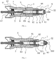
Fig. 1 is a schematic view showing the structure according to the present invention. -
Fig. 2 is a structural schematic view showing the pull-rivet state according to the present invention. -
Fig. 3 is a structural schematic view showing the pull-rivet state completes according to the present invention. -
Fig. 4 is a diagram showing the screw pair conversion according to the present invention. -
Fig. 5 is a structural schematic view showing the safety valve mechanism according to another embodiment of the present invention. -
Fig. 6 is a schematic structural view of a portion of the two-way safety valve according to the present invention. -
Fig. 7a is an analysis diagram showing screw pair pre-loading force and screw pair conversion position of the pull-rivet tool accessory without built-in safety valve structure during the pull-rivet stroke. -
FIG. 7b is an analysis diagram showing screw pair pre-loading force and screw pair conversion position according to the present invention. - In the figures,
cylindrical handle 1,annular groove 11,elastic ring 12,avoidance observation notch 13, rivetingfastener 100, rotatingpart 2,transmission part 3, axial through hole, threadedstructure 4, connectingpart 5, connectingportion 51 ,loading screw 52, guidingnozzle assembly 6, frontouter sleeve 61, cylindrical guidingnozzle 62,compression preload spring 7,safety valve mechanism 8,valve core 81,spring 82 ,valve cavity 83, adjustingscrew 84, low pressure overloadprotection safety valve 85,locking sleeve 9. - As shown in
figures 1 -3 , the riveting tool accessory comprises acylindrical handle 1, which is provided with arotating part 2 through thecylindrical handle 1, therotating part 2 is positioned axially and rotatably circumferentially connected to thecylindrical handle 1; and atransmission part 3 that is circumferentially positioned and axially movably connected to thecylindrical handle 1, wherein therotating part 2 and thetransmission part 3 are connected by a threadedstructure 4, and when therotating part 2 rotates forward or reverse, thetransmission part 3 can be driven to retreat or advance. The front end of thetransmission part 3 is provided with a connectingpart 5, the front end of the connectingpart 5 can be mounted with ariveting fastener 100 ,the front end of thecylindrical handle 1 is provided with a guidingnozzle assembly 6, the connectingpart 5 is disposed through the guidingnozzle assembly 6 and the front end of the connectingpart 5 can extend out of the guidingnozzle assembly 6, a compression preloadingspring 7 is disposed between thetransmission part 3 and the guidingnozzle assembly 6, asafety valve mechanism 8 is disposed between thetransmission part 3 and the connectingpart 5, and thesafety valve mechanism 8 enables the screw pair conversion of the threadedstructure 4 to occur before the rivetedfastener 100 mounted on the front end of the connectpart 5 contact the guidingnozzle assembly 6.Fig. 4 is a diagram showing the screw pair conversion according to the present invention. The left shows the first crew pair contact, the middle shows the period during the screw pair conversion and the right shows the second screw pair contact. - The rotating
part 2 is a screw, thetransmission part 3 is a cylinder, and the front end of the screw and the rear end of the cylinder can be connected by the threadedstructure 4; thesafety valve mechanism 8 comprises avalve core 81, thevalve core 81 is arranged in the cylinder and acted as a block in the middle of the cylinder, and aspring 82 arranged between thevalve core 81 and the connectpart 5, thespring 82 acts on theconnect part 5 on one end and acts on thevalve core 81 on the other end, avalve cavity 83 is formed between the screw, the cylinder and thevalve core 81, the volume of thevalve cavity 83 can change according to the axial relative position of the screw and the cylinder to change the pressure inside, thevalve cavity 83 is provided with a medium, and the medium is a gas or a fluid. As an alternative solution, as shown inFig. 5 , therotating part 2 has a screw hole, thetransmission part 3 has a threaded post, and the screw hole and the threaded post can be screwed; thesafety valve mechanism 8 comprises an axial through hole disposed on thetransmission part 3 and avalve core 81 disposed in the axial through hole and acted as a block in the middle of the axial through hole, wherein aspring 82 is disposed between thevalve core 81 and the connectingpart 5, thespring 82 acts on the connectingpart 5 on one end and acts on thevalve core 81 on the other end, and avalve cavity 83 is formed between therotating part 2, thetransmission part 3 and thevalve core 81, the volume of thevalve cavity 83 can change according to the axial relative position of the rotatingpart 2 and thetransmission part 3 to change the pressure inside, thevalve cavity 83 is provided with a medium, and the medium is a gas or a fluid. Obviously, if there is a loop system, the medium in thevalve cavity 83 can also be other types of medium. - To make the
valve core 81 act as a block in the middle of the cylinder or the axial through hole, an annular step is formed in the cylinder or the axial through hole as a valve seat for thevalve core 81. Taking into account cost, heat dissipation, stiffness, correct opening of the valve, returning to the seat and its performance requirements, thevalve core 81 can adopt a rigid or elastic sphere, a hemisphere or the like, or other cylinders and sleeves without a pressure outlet structure, or any flat plates, sleeves and cylinders having a different surface structure on its upper surface in the present invention. By doing so, when there is external force or the medium pressure inside thevalve cavity 83 is greater than the pressure applied to thevalve core 81 by the compression preload of the compression pre-loadingspring 82, automatic opening and closing action can be performed. - The
safety valve mechanism 8 is a pressure adjustable safety valve mechanism or a fixed pressure safety valve mechanism, and if the safety valve mechanism is a fixed pressure safety valve mechanism, the safety valve mechanism is provided with an adjusting structure capable of adjusting the compression degree of the spring and/or the safety valve mechanism is provided a spring replacement structure capable of replacing different spring with different specifications. Specifically, the adjustment structure comprises an adjustingscrew 84 provided in the cylinder or the axial through hole and close to one end of the connectingpart 5, thespring 82 acts on the adjustingscrew 84 on one end and acts on thevalve core 81 on the other end. Further, thesafety valve mechanism 8 is a one-way safety valve mechanism, and when the pressure in thevalve cavity 83 is greater than the pre-loading force of thespring 82, thevalve core 81 can be pushed open to relieve pressure; or thesafety valve mechanism 8 is a two-way safety valve mechanism, and a low-pressure overloadprotection safety valve 85 is provided on thesafety valve mechanism 8, and the low-pressure overloadprotection safety valve 85 is capable of increasing the pressure when the pressure in thevalve cavity 83 is less than a set value, and push thevalve core 81 open to relieve pressure when the pressure in thevalve cavity 83 is greater than the preloading force of thespring 82. - In order to facilitate understanding of the different types of
safety valve mechanisms 8 , various types ofsafety valve mechanisms 8 are further described below: thesafety valve mechanism 8 is a device for thresholding the working pressure of the medium in thevalve cavity 83. The medium pressure in thevalve cavity 83 is mainly derived from the change of the medium temperature, the increase or decrease of the medium in the volume of thevalve cavity 83, or the volume/temperature changes caused by pressuring/decompressing device working on quantitative medium in the volume of the closedvalve cavity 83. The one-way spring pre-loadingsafety valve mechanism 8 is a type of safety valve. The one-way spring pre-loading safety valve mechanism utilizes the force of the compression spring to balance the force exerted by the medium on thevalve core 81. The maximum allowable pressure threshold of the safety valve mechanism is determined by the preloading compression of the spring. When the force of the medium in thevalve cavity 83 on thevalve core 81 is less than the force of thepre-pressure spring 82 on thevalve core 81, thevalve core 81 is in a closed state; when the force of the medium in thevalve cavity 83 on thevalve core 81 is greater than the force of thepre-pressure spring 82 on thevalve core 81, thespring 82 is compressed to cause thevalve core 81 to leave the valve seat, and the valve is automatically opened; when the force of the medium in thevalve cavity 83 on thevalve core 81 is less than the pre-loading force of thespring 82, the pressure of thespring 82 pushes thevalve core 81 back to the valve seat, and the valve is automatically closed. According to the different direction of the force of thespring 82 to thevalve core 81, the spring preloading safety valve mechanism can be divided into a low-pressure protection safety valve and a high-pressure protection safety valve. Since the force of thespring 82 on thevalve core 81 is one-way, such spring preload safety valve mechanisms can be collectively referred to one-way safety valves. When thespring 82 is embedded outside thevalve cavity 83 of the safety valve, the function of the safety valve mechanism is high-voltage overload protection; when the pre-pressure spring is embedded in thesafety valve cavity 83, and the pressure overload protection means the low-voltage overload protection. Typically, the safety valve core has a passage connected to the pressure outlet on the side of the preload. According to the pre-loading spring embedded position, the pre-loading pressure type safety valve can be divided into a low-pressure protection safety valve and a high-pressure protection safety valve, but only functions as a one-way pressure overload protection. The safety valve can be divided into a pressure-adjustable safety valve and a fixed-pressure safety valve according to whether the compression amount of the pre-loading spring is variable. The preloaded pressure safety valve mechanism is light and compact, has high sensitivity, is unrestricted in installation position. Due to its low sensitivity to vibration, it can be used on mobile devices in addition to fixing devices or pipes. The one-way preloaded pressure safety valve is widely used as a safety device for overpressure (low pressure or high pressure) protection in various related industries. If the valve has both a low pressure and high-pressure protection, the safety valve is a two-way safety valve. In this case, the working pressure of the medium in the valve cavity connected with the two-way safety valve will be defined in a certain pressure threshold range. The valve core will close when the medium operating pressure is within the threshold range; the valve core will automatically open when the working pressure of the medium exceeds the threshold range; when the working pressure of the medium returns to the threshold range of the safety valve, the valve core will automatically return to the seat. Regarding the structural design of the two-way safety valve, there are usually directional or other specific requirements for installation. Obviously, in the present invention, thesafety valve mechanism 8 can also be a two-way safety valve mechanism. Thesafety valve mechanism 8 is provided with a low-pressure overloadprotection safety valve 85 configured to increase the pressure in thevalve cavity 83 when the pressure in thevalve cavity 83 is less than a set value, and push thevalve core 81 open to relieve pressure when the pressure in thevalve cavity 83 is greater than the preload of thespring 82. If the one-way safety valve mechanism of the present invention is changed to a two-way safety valve mechanism, bidirectional (positive pressure and negative pressure) threshold settings for the medium pressure in the valve cavity can be achieved. For example, as shown inFig. 6 , a low pressure overloadprotection safety valve 85 is provided on thevalve core 81. The working pressure of the medium in the valve cavity will be limited to the range of the positive pressure threshold and the negative pressure threshold; it can also be achieved by place a separate low pressure overload protection safety valve at other location or other components such as the side of the cylinder or the front end of the screw within the closed valve cavity; or directly replace thevalve core 81 with any suitable type of two-way safety valve, and adapt the two-way safety valve and the pre-loading spring associated with this change so as to limit the working pressure of the medium in the valve cavity to the range of the positive pressure threshold and negative pressure threshold, because thevalve core 81 of the safety valve mechanism is closed when the working pressure in the valve cavity is within the threshold range, so such cases are also included in the scope of protection of the present invention . In this case, the threshold range of the two-way safety valve may be unidirectionally adjustable or bidirectionally adjustable. - As shown in
Figures 1-3 , more specifically, the connectingpart 5 comprises a connectingportion 51 detachably fixed to thetransmission part 3, and aloading screw 52 provided at the connectingportion 51, and theloading screw 52 is disposed through the guidingnozzle assembly 6 and the front end of theloading screw 52 can extend outside the guidingnozzle assembly 6. Theloading screw 52 can be coupled to arivet fastener 100, such as a pull-rivet screw. The guidingnozzle assembly 6 comprises a frontouter sleeve 61 and acylindrical guiding nozzle 62 detachably fixed to the front end of the frontouter sleeve 61, and the rear end of the frontouter sleeve 61 is connected with the front end of thecylindrical handle 1 through a locking connection structure. In particular, the locking connection structure comprises a threaded connection structure provided between the front end of thecylindrical handle 1 and the rear end of the frontouter sleeve 61, and a lockingsleeve 9 is screwed onto the frontouter sleeve 61 and the lockingsleeve 9 abuts against the front end surface of thecylindrical handle 1 ; thecompression preloading spring 7 acts on the frontouter sleeve 61 on one end and acts on thetransmission part 3 on the other end. Thecylindrical handle 1 is provided with anannular groove 11 in the rear end, and anelastic sleeve ring 12 is provided in theannular groove 11, the rear end surface of thecylindrical handle 1 is provided with at least oneavoidance observation notch 13. - The working process of the present invention is as follows:
As shown inFig. 1 , as the pull-rivet stroke starts, theloading screw 52 is in the front end limit position and is amounted with a pull-rivet nut matching the front end thread of theloading screw 52, the thesafety valve mechanism 8 is in a closed state. The threadedstructure 4 between therotating part 2 and thetransmission part 3 begins to enter the engaged state. Driven by therotating part 2, the transmittingpart 3 and therotating part 2 are moved toward each other, and the medium in thevalve cavity 83 is compressed, and the medium pressure is increased. Before the medium pressure in thevalve cavity 83 reaches the maximum pressure threshold of the medium, the medium pressure in thevalve cavity 83 varies with the relative position of therotating part 2 and thetransmission part 3, and thevalve body 81 is normally closed. If the medium pressure of the compressed medium in thevalve cavity 83 exceeds the maximum allowable medium pressure threshold of thevalve cavity 83 , the thrust of the compressed medium against thevalve core 81 exceeds the preloading force of thespring 82, and the valve is automatically depressurized until the maximum allowable medium pressure threshold is obtained. Therotating part 2 and thetransmission part 3 are threadedly engaged, and therotating part 2 and thecylindrical handle 1 are connected by a thrust ball bearing to form an axial and radial limit connection. The compressed medium within thevalve cavity 83 forms a preload. At the same time, as therotating part 2 rotates, thetransmission part 3 is driven to move backward, the compression amount of thecompression pre-loading spring 7 is gradually reduced. Thecompression pre-loading spring 7 and thesafety valve mechanism 8 have opposite directions of force on the screw pair. - As shown in
FIG. 2 , the rotation of therotating part 2 causes thetransmission part 3 to drive theloading screw 52 to move backward to the rear end surface of the pull-rivet nut to maintain a certain pressure contact with the front end surface of the cylindrical guidingnozzle 62, but the pressure is insufficient to deform the rivet nut plastically. In this case, the pre-loading rivet nut on the tool can be inserted vertically into the pre-made hole on the workpiece, and then the transmission part continues to rotate in the same direction to start loading the pull-rivet load. - As shown in
Fig. 3 , the pull-rivet nut is plastically deformed to a certain extent by the pull-rivet load, and the pull-rivet nut process ends when the pull-rivet nut is fastened to the workpiece. - Finally, changing the steering of the power tool causes the pull-rivet screw to follow or manually pull the pull-rivet screw out of the nut, and the pull-rivet nut process ends.
-
Fig. 7a and Fig. 7b are analysis diagrams showing screw pair pre-loading force and screw pair conversion position during the pull-rivet stroke according to the pull-rivet tool accessory without built-in safety valve structure and the present invention, respectively. In the figure, the X axis represents the pull-rivet stroke and the Y axis represents the preload force on the screw pair. -
Fig. 7a is an analysis diagram showing screw pair pre-loading force and screw pair conversion position of the pull-rivet tool accessory without built-in safety valve structure during the pull-rivet stroke. - 201- the starting point of pull-rivet stroke of the pull-rivet tool accessory without built-in safety valve structure;
- 202- the starting point of nut pull-rivet of the pull-rivet tool accessory without built-in safety valve structure;
- 203- the completion point of nut pull-rivet of the pull-rivet tool accessory without built-in safety valve structure;
- 204- the completion point of the screw pair conversion of the pull-rivet tool accessory without built-in safety valve structure.
- The pre-loading force at the
starting point 201 of pull-rivet stroke of the pull-rivet tool accessory without built-in safety valve structure is applied by the pre-loadingcompression spring 7 to solve the problem of thread re-entry, but the screw pair is still exiting screw pair. At thestarting point 202 of nut pull-rivet, the power tool starts to load, but at this time, it is necessary to overcome the pre-loading force on the exiting screw pair to convert the screw pair to the pull-rivet screw pair, and the screw transmission mechanism can start to convert the torque loaded by the power tool to the pull-rivet load on the pull-rivet nut, so the screw pairconversion completion point 204 is located after the nut pull-rivet starting point 202. The distance betweenpoint 202 andpoint 204 is the inter-thread clearance, and the thread wear increases the inter-thread clearance. -
FIG. 7b is an analysis diagram showing screw pair pre-loading force and screw pair conversion position according to the present invention. - 301 - the starting point of pull-rivet stroke of the present invention;
- 302- the starting point of nut pull-rivet of the present invention;
- 303- the completion point of nut pull-rivet of the present invention;
- 304 - the completion point of the screw pair conversion of the present invention.
- The pre-loading force of the
starting point 301 of pull-rivet stroke of the present invention is also applied by the pre-loadingcompression spring 7 to solve the problem of thread re-entry, but the screw pair is also exiting the screw pair. Before thestarting point 302 of nut pull-rivet, the power tool rotates to pressurize the safety valve, the safety valve begins to intervene in the movement of the thread transmission mechanism, and the medium pressure in the valve cavity of the safety valve exerts an axial preloading force on the screw pair, but the direction is opposite with the pre-loading force applied by the pre-loadingcompression spring 7, but when the combined force of these two pre-loading forces from two directions is 0 , the screw pair starts to converse, so in the present invention the screw pairconversion completion point 304 is located before thestarting point 302 of nut pull-rivet. Because the screw pair has been converted from the exiting screw pair to the pull-rivet screw pair and pre-loaded at thestarting point 302 of nut pull-rivet, the power tool can directly load the pull-rivet load on the pull-rivet nut through the screw transmission mechanism. - A riveting device comprising a riveting tool and the riveting tool accessory, wherein the riveting tool comprises a driving device, the riveting tool accessory is connectable to the driving device, and a power output shaft of the driving device is connected to the rotating part, the driving device is an electric drive or a manual drive.
- Although more commonly used herein, the terms such as
cylindrical handle 1,annular groove 11,elastic ring 12,avoidance observation notch 13,riveting fastener 100,rotating part 2,transmission part 3, axial through hole, threadedstructure 4, connectingpart 5, connectingportion 51, loadingscrew 52 , guidingnozzle assembly 6, frontouter sleeve 61, cylindrical guidingnozzle 62,compression pre-loading spring 7,safety valve mechanism 8,valve core 81,spring 82,valve cavity 83, adjustingscrew 84, low-voltage overloadprotection safety valve 85, lockingsleeve 9, etc., do not preclude the possibility of using other terms. These terms are only used to describe and explain nature of invention more conveniently.
Claims (10)
- A riveting tool accessory, comprising a cylindrical handle(1), which is provided with a rotating part(2) through the cylindrical handle(1), the rotating part(2) is positioned axially and rotatably circumferentially connected to the cylindrical handle(1); and a transmission part(3) that is circumferentially positioned and axially movably connected to the cylindrical handle(1), wherein the rotating part(2) and the transmission part(3) are connected by a threaded structure(4), and when the rotating part(2) rotates forward or reverse, the transmission part(3) can be driven to retreat or advance, wherein: the front end of the transmission part(3) is provided with a connecting part(5), the front end of the connecting part(5) can be mounted with a riveting fastener(100) ,the front end of the cylindrical handle(1) is provided with a guiding nozzle assembly(6), the connecting part ( 5 ) is disposed through the guiding nozzle assembly (6) and the front end of the connecting part (5) can extend out of the guiding nozzle assembly (6), a compression preloading spring (7) is disposed between the transmission part (3) and the guiding nozzle assembly (6), characterized in that a safety valve mechanism(8) is disposed between the transmission part (3) and the connecting part (5), and the safety valve mechanism (8) is configured to enable the screw pair conversion of the threaded structure (4) to occur before the riveted fastener (100) mounted on the front end of the connecting part(5) contacts the guiding nozzle assembly(6).
- A riveting tool accessory in accordance with claim 1, wherein: the rotating part(2) is a screw, the transmission part(3) is a cylinder, and the front end of the screw and the rear end of the cylinder are connected by the threaded structure(4);the safety valve mechanism(8) comprises a valve core(81), the valve core(81) is arranged in the cylinder and acts as a block in the middle of the cylinder, and aspring(82) arranged between the valve core(81) and the connecting part(5), the spring(82) acts on the connecting part(5) on one end and acts on the valve core(81) on the other end, a valve cavity(83) is formed between the screw, the cylinder and the valve core(81), the volume of the valve cavity(83) can change according to the axial relative position of the screw and the cylinder to change the pressure inside, the valve cavity(83) is provided with a medium, and the medium is a gas or a fluid.
- A riveting tool accessory in accordance with claim 1, wherein: the rotating part(2) has a screw hole, the transmission part(3) has a threaded post, and the screw hole and the threaded post are screwed; the safety valve mechanism(8) comprises an axial through hole disposed on the transmission part(3) and a valve core(81) disposed in the axial through hole and acts as a block in the middle of the axial through hole, wherein a spring (82) is disposed between the valve core(81) and the connecting part(5), the spring(82) acts on the connecting part(5) on one end and acts on the valve core(81) on the other end, and a valve cavity(83) is formed between the rotating part(2), the transmission part(3) and the valve core(81), the volume of the valve cavity(83) can change according to the axial relative position of the rotating part(2) and the transmission part(3) to change the pressure inside, the valve cavity(83) is provided with a medium, and the medium is a gas or a fluid.
- A riveting tool accessory in accordance with claim 2 or claim 3, wherein: the safety valve mechanism(8) is a pressure adjustable safety valve mechanism or a fixed pressure safety valve mechanism, and if the safety valve mechanism(8) is a fixed pressure safety valve mechanism, the safety valve mechanism(8) is provided with an adjusting structure capable of adjusting the compression degree of the spring (82) and/or the safety valve mechanism (8) is provided with a spring replacement structure capable of replacing different spring(82) with different specifications.
- A riveting tool accessory in accordance with claim 4, wherein: the adjustment structure comprises an adjusting screw(84) provided in the cylinder or the axial through hole and close to one end of the connecting part(5) , the spring(82) acts on the adjusting screw (84) on one end and acts on the valve core(81) on the other end.
- A riveting tool accessory in accordance with claim 5, wherein: the connecting part(5) comprises a connecting portion(51) detachably fixed to the transmission part(3), and a loading screw(52) provided at the connecting portion(51), and the loading screw(52) is disposed through the guiding nozzle assembly(6) and the front end of the loading screw(52) can extend outside the guiding nozzle assembly(6).
- A riveting tool accessory in accordance with claim 6, wherein: the guiding nozzle assembly(6) comprises a front outer sleeve(61) and a cylindrical guiding nozzle(62) detachably fixed to the front end of the front outer sleeve(61), and the rear end of the front outer sleeve(61) is connected with the front end of the cylindrical handle(1) through a locking connection structure.
- A riveting tool accessory in accordance with claim 7, wherein: the locking connection structure comprises a threaded connection structure provided between the front end of the cylindrical handle(1) and the rear end of the front outer sleeve(61), and a locking sleeve(9) is screwed onto the front outer sleeve(61) and the locking sleeve(9) abuts against the front end surface of the cylindrical handle(1) ; the compression preloading spring(7) acts on the front outer sleeve(61) on one end and acts on the transmission part(3) on the other end.
- A riveting tool accessory in accordance with claim 2 or claim 3, wherein: the safety valve mechanism(8) is a one-way safety valve mechanism, and when the pressure in the valve cavity(83) is greater than the pre-loading force of the spring(82), the valve core(81) can be pushed open to relieve pressure; or the safety valve mechanism(8) is a two-way safety valve mechanism, and a low-pressure overload protection safety valve(85) is provided on the safety valve mechanism(8), and the low-pressure overload protection safety valve(85) is configured to increase the pressure when the pressure in the valve cavity(83) is less than a set value, and push the valve core(81) open to relieve pressure when the pressure in the valve cavity(83) is greater than the preloading force of the spring(82).
- A riveting device comprising a riveting tool and the riveting tool accessory in accordance with any one of claims 1-9, wherein the riveting tool comprises a driving device, the riveting tool accessory is connectable to the driving device, and a power output shaft of the driving device is connected to the rotating part of the riveting tool accessory, the driving device is an electric drive or a manual drive.
Applications Claiming Priority (2)
| Application Number | Priority Date | Filing Date | Title |
|---|---|---|---|
| CN201710121912.8A CN106976044B (en) | 2017-03-02 | 2017-03-02 | Riveting tool accessory and riveting tool |
| PCT/CN2018/077117 WO2018157764A1 (en) | 2017-03-02 | 2018-02-24 | Riveting tool accessory and riveting tool |
Publications (3)
| Publication Number | Publication Date |
|---|---|
| EP3590661A1 EP3590661A1 (en) | 2020-01-08 |
| EP3590661A4 EP3590661A4 (en) | 2021-01-27 |
| EP3590661B1 true EP3590661B1 (en) | 2022-07-27 |
Family
ID=59338713
Family Applications (1)
| Application Number | Title | Priority Date | Filing Date |
|---|---|---|---|
| EP18760548.0A Active EP3590661B1 (en) | 2017-03-02 | 2018-02-24 | Riveting tool accessory and riveting device |
Country Status (4)
| Country | Link |
|---|---|
| US (1) | US11413680B2 (en) |
| EP (1) | EP3590661B1 (en) |
| CN (1) | CN106976044B (en) |
| WO (1) | WO2018157764A1 (en) |
Families Citing this family (12)
| Publication number | Priority date | Publication date | Assignee | Title |
|---|---|---|---|---|
| CN106976044B (en) * | 2017-03-02 | 2023-04-25 | 杭州联伟科技有限公司 | Riveting tool accessory and riveting tool |
| IT201800003162A1 (en) * | 2018-03-01 | 2019-09-01 | Gorgia Roberto & C S N C | Multifunction mechanical device |
| CN108856531A (en) * | 2018-05-28 | 2018-11-23 | 成都飞机工业(集团)有限责任公司 | A kind of manual earless molding machine |
| MX2021005589A (en) * | 2018-11-13 | 2021-08-05 | Penn Eng & Mfg Corp | HOLDER FOR THIN SHEET MATERIAL. |
| CN110695294B (en) * | 2019-10-10 | 2025-03-25 | 杭州联伟科技有限公司 | Power riveting tool accessories with safety side handles and power riveting tools |
| CN111790877B (en) * | 2020-07-29 | 2025-05-13 | 浙江路得坦摩汽车部件股份有限公司 | A processing device for rivet connection of shock absorber |
| CN114012023B (en) * | 2021-10-31 | 2023-10-03 | 东风商用车有限公司 | Riveting device and riveting method for self-guiding of rivet |
| CN114148720B (en) * | 2021-12-28 | 2025-08-29 | 迈得医疗工业设备股份有限公司 | Accessory reversing mechanism |
| CN115446868B (en) * | 2022-09-23 | 2025-05-16 | 杭州申昊科技股份有限公司 | A mechanical arm end-operating tool integrating pressing and screwing |
| DE102023116738B3 (en) * | 2023-06-26 | 2024-10-31 | Tkr Spezialwerkzeuge Gmbh | Hand-held pull and push device |
| CN117181983B (en) * | 2023-11-07 | 2024-02-02 | 山西建业锻压股份有限公司 | Clamping and rotating device for forging processing and using method |
| DE102024105644A1 (en) * | 2024-02-28 | 2025-08-28 | Weber Schraubautomaten Gesellschaft mit beschränkter Haftung | Device for setting a setting element and method for exchanging a tool on such a device |
Family Cites Families (20)
| Publication number | Priority date | Publication date | Assignee | Title |
|---|---|---|---|---|
| GB555713A (en) * | 1941-12-30 | 1943-09-03 | Chicago Pneumatic Tool Co | Rivet setting tool |
| US3626745A (en) * | 1969-12-01 | 1971-12-14 | Richline Co Inc The | Rivet gun accessory |
| GB1462172A (en) * | 1973-01-12 | 1977-01-19 | Avdel Ltd | Fastener placing apparatus |
| US4074554A (en) * | 1973-03-29 | 1978-02-21 | Aerpat A.G. | Fastener placing apparatus |
| US4070889A (en) * | 1976-10-14 | 1978-01-31 | Textron Inc. | Linear pull setting tool |
| DE3306827C2 (en) * | 1983-02-26 | 1986-05-07 | Gesipa Blindniettechnik Gmbh, 6000 Frankfurt | Pneumatic-hydraulic setting tool for blind rivet nuts |
| US5572900A (en) * | 1994-08-01 | 1996-11-12 | The Deutsch Company | Reduced recoil bucking bar |
| ES2144906B1 (en) | 1996-09-03 | 2001-02-01 | Perez Aniento Andres | UNIVERSAL SIMPLIFIED RIVER. |
| ATE219398T1 (en) * | 1997-07-28 | 2002-07-15 | Ober S P A | PNEUMATIC-HYDRAULIC RIVETER |
| GB2390833B (en) * | 2002-07-18 | 2005-09-14 | Emhart Llc | Method and apparatus for monitoring blind fastener setting |
| JP3993844B2 (en) * | 2003-08-18 | 2007-10-17 | 株式会社ロブテックス | Riveter |
| CN2822887Y (en) * | 2005-09-06 | 2006-10-04 | 王荣林 | Automatic riveter for reveting screw nut |
| DE102006026552A1 (en) * | 2006-06-08 | 2007-12-13 | Gustav Klauke Gmbh | Method for operating a hydraulic pressing device and hydraulic pressing device with a hydraulic pump |
| CN201271720Y (en) * | 2008-10-13 | 2009-07-15 | 何崇源 | Nail puller |
| DE102011111533C5 (en) * | 2011-08-31 | 2025-12-11 | WS Wieländer + Schill Engineering GmbH & Co. KG | Pressure generator for a pulling or pressing device as well as pulling or pressing device |
| CN203830640U (en) * | 2014-05-19 | 2014-09-17 | 高良 | Electric blind rivet gun |
| US9440340B2 (en) * | 2014-06-11 | 2016-09-13 | Techway Industrial Co., Ltd. | Electric rivet nut tool and control device thereof |
| CN104999410B (en) * | 2015-07-17 | 2017-03-22 | 上海特倍孚铆接工具制造有限公司 | Electric rivet nut tool |
| CN206588906U (en) * | 2017-03-02 | 2017-10-27 | 杭州联团科技有限公司 | Clincher tool annex and clincher tool |
| CN106976044B (en) * | 2017-03-02 | 2023-04-25 | 杭州联伟科技有限公司 | Riveting tool accessory and riveting tool |
-
2017
- 2017-03-02 CN CN201710121912.8A patent/CN106976044B/en active Active
-
2018
- 2018-02-24 US US16/490,882 patent/US11413680B2/en active Active
- 2018-02-24 WO PCT/CN2018/077117 patent/WO2018157764A1/en not_active Ceased
- 2018-02-24 EP EP18760548.0A patent/EP3590661B1/en active Active
Also Published As
| Publication number | Publication date |
|---|---|
| EP3590661A1 (en) | 2020-01-08 |
| CN106976044A (en) | 2017-07-25 |
| US11413680B2 (en) | 2022-08-16 |
| WO2018157764A1 (en) | 2018-09-07 |
| US20200139426A1 (en) | 2020-05-07 |
| CN106976044B (en) | 2023-04-25 |
| EP3590661A4 (en) | 2021-01-27 |
Similar Documents
| Publication | Publication Date | Title |
|---|---|---|
| US11413680B2 (en) | Riveting tool accessory and riveting tool | |
| EP3590625B1 (en) | Riveting tool chuck and riveting tool | |
| US20260085713A1 (en) | Hydraulic power tool | |
| CN103561915B (en) | fluid power tool | |
| US8935948B1 (en) | Electric-hydraulic riveter and crimper hand power tool | |
| EP2093024A1 (en) | Electro-hydraulic device with an electronic control for deforming fastening elements | |
| WO2008032341A1 (en) | Hydraulic pressing and/or cutting tool and mechanism for converting a rotary motion into a translational oscillating motion for this tool | |
| EP2009291B1 (en) | Press-driven tool actuation system | |
| US12343855B2 (en) | Spring element and coupling device | |
| US8607674B2 (en) | Manually driven and self-contained, controlled tightening hydraulic wrench | |
| US20240131604A1 (en) | Hydraulic Power Tool | |
| EP4142981B1 (en) | Feeding structure and fastening device | |
| CN206588906U (en) | Clincher tool annex and clincher tool | |
| CN110695294B (en) | Power riveting tool accessories with safety side handles and power riveting tools | |
| US10400798B2 (en) | Hydraulic unit for a mobile hydraulic tool | |
| EP1820605B1 (en) | Air Driver Device | |
| EP4427872A2 (en) | Hydraulic tool having ram piston with integrated overload assembly | |
| CN223536654U (en) | A hydraulic buffer device for automotive steering valve sleeve | |
| CN223854814U (en) | Worm gear speed reducer auto-lock unblock structure | |
| CN219838229U (en) | Slider mechanism of multi-station unbalanced load press | |
| CN220839934U (en) | Electric tool | |
| CN224239435U (en) | A hydraulic wrench | |
| US20220307525A1 (en) | Regulator unit | |
| EP3254786B1 (en) | Tailstock transferring apparatus | |
| CN118305243A (en) | Self-locking swivel nut flaring installation tool |
Legal Events
| Date | Code | Title | Description |
|---|---|---|---|
| STAA | Information on the status of an ep patent application or granted ep patent |
Free format text: STATUS: THE INTERNATIONAL PUBLICATION HAS BEEN MADE |
|
| PUAI | Public reference made under article 153(3) epc to a published international application that has entered the european phase |
Free format text: ORIGINAL CODE: 0009012 |
|
| STAA | Information on the status of an ep patent application or granted ep patent |
Free format text: STATUS: REQUEST FOR EXAMINATION WAS MADE |
|
| 17P | Request for examination filed |
Effective date: 20191002 |
|
| AK | Designated contracting states |
Kind code of ref document: A1 Designated state(s): AL AT BE BG CH CY CZ DE DK EE ES FI FR GB GR HR HU IE IS IT LI LT LU LV MC MK MT NL NO PL PT RO RS SE SI SK SM TR |
|
| AX | Request for extension of the european patent |
Extension state: BA ME |
|
| DAV | Request for validation of the european patent (deleted) | ||
| DAX | Request for extension of the european patent (deleted) | ||
| A4 | Supplementary search report drawn up and despatched |
Effective date: 20210112 |
|
| RIC1 | Information provided on ipc code assigned before grant |
Ipc: B25B 27/00 20060101ALI20201221BHEP Ipc: B21J 15/38 20060101ALI20201221BHEP Ipc: B25F 3/00 20060101AFI20201221BHEP Ipc: B21J 15/04 20060101ALI20201221BHEP Ipc: B21J 15/26 20060101ALI20201221BHEP Ipc: B21J 15/28 20060101ALI20201221BHEP Ipc: F16B 37/06 20060101ALI20201221BHEP Ipc: B21J 15/10 20060101ALI20201221BHEP |
|
| GRAP | Despatch of communication of intention to grant a patent |
Free format text: ORIGINAL CODE: EPIDOSNIGR1 |
|
| STAA | Information on the status of an ep patent application or granted ep patent |
Free format text: STATUS: GRANT OF PATENT IS INTENDED |
|
| RIC1 | Information provided on ipc code assigned before grant |
Ipc: B25B 27/00 20060101ALI20220202BHEP Ipc: B21J 15/28 20060101ALI20220202BHEP Ipc: B21J 15/10 20060101ALI20220202BHEP Ipc: F16B 37/06 20060101ALI20220202BHEP Ipc: B21J 15/26 20060101ALI20220202BHEP Ipc: B21J 15/38 20060101ALI20220202BHEP Ipc: B21J 15/04 20060101ALI20220202BHEP Ipc: B25F 3/00 20060101AFI20220202BHEP |
|
| INTG | Intention to grant announced |
Effective date: 20220304 |
|
| GRAS | Grant fee paid |
Free format text: ORIGINAL CODE: EPIDOSNIGR3 |
|
| GRAA | (expected) grant |
Free format text: ORIGINAL CODE: 0009210 |
|
| STAA | Information on the status of an ep patent application or granted ep patent |
Free format text: STATUS: THE PATENT HAS BEEN GRANTED |
|
| AK | Designated contracting states |
Kind code of ref document: B1 Designated state(s): AL AT BE BG CH CY CZ DE DK EE ES FI FR GB GR HR HU IE IS IT LI LT LU LV MC MK MT NL NO PL PT RO RS SE SI SK SM TR |
|
| REG | Reference to a national code |
Ref country code: CH Ref legal event code: EP |
|
| REG | Reference to a national code |
Ref country code: AT Ref legal event code: REF Ref document number: 1506767 Country of ref document: AT Kind code of ref document: T Effective date: 20220815 |
|
| REG | Reference to a national code |
Ref country code: DE Ref legal event code: R096 Ref document number: 602018038485 Country of ref document: DE |
|
| REG | Reference to a national code |
Ref country code: IE Ref legal event code: FG4D |
|
| REG | Reference to a national code |
Ref country code: LT Ref legal event code: MG9D |
|
| REG | Reference to a national code |
Ref country code: NL Ref legal event code: MP Effective date: 20220727 |
|
| PG25 | Lapsed in a contracting state [announced via postgrant information from national office to epo] |
Ref country code: SE Free format text: LAPSE BECAUSE OF FAILURE TO SUBMIT A TRANSLATION OF THE DESCRIPTION OR TO PAY THE FEE WITHIN THE PRESCRIBED TIME-LIMIT Effective date: 20220727 Ref country code: RS Free format text: LAPSE BECAUSE OF FAILURE TO SUBMIT A TRANSLATION OF THE DESCRIPTION OR TO PAY THE FEE WITHIN THE PRESCRIBED TIME-LIMIT Effective date: 20220727 Ref country code: PT Free format text: LAPSE BECAUSE OF FAILURE TO SUBMIT A TRANSLATION OF THE DESCRIPTION OR TO PAY THE FEE WITHIN THE PRESCRIBED TIME-LIMIT Effective date: 20221128 Ref country code: NO Free format text: LAPSE BECAUSE OF FAILURE TO SUBMIT A TRANSLATION OF THE DESCRIPTION OR TO PAY THE FEE WITHIN THE PRESCRIBED TIME-LIMIT Effective date: 20221027 Ref country code: NL Free format text: LAPSE BECAUSE OF FAILURE TO SUBMIT A TRANSLATION OF THE DESCRIPTION OR TO PAY THE FEE WITHIN THE PRESCRIBED TIME-LIMIT Effective date: 20220727 Ref country code: LV Free format text: LAPSE BECAUSE OF FAILURE TO SUBMIT A TRANSLATION OF THE DESCRIPTION OR TO PAY THE FEE WITHIN THE PRESCRIBED TIME-LIMIT Effective date: 20220727 Ref country code: LT Free format text: LAPSE BECAUSE OF FAILURE TO SUBMIT A TRANSLATION OF THE DESCRIPTION OR TO PAY THE FEE WITHIN THE PRESCRIBED TIME-LIMIT Effective date: 20220727 Ref country code: FI Free format text: LAPSE BECAUSE OF FAILURE TO SUBMIT A TRANSLATION OF THE DESCRIPTION OR TO PAY THE FEE WITHIN THE PRESCRIBED TIME-LIMIT Effective date: 20220727 Ref country code: ES Free format text: LAPSE BECAUSE OF FAILURE TO SUBMIT A TRANSLATION OF THE DESCRIPTION OR TO PAY THE FEE WITHIN THE PRESCRIBED TIME-LIMIT Effective date: 20220727 |
|
| REG | Reference to a national code |
Ref country code: AT Ref legal event code: MK05 Ref document number: 1506767 Country of ref document: AT Kind code of ref document: T Effective date: 20220727 |
|
| PG25 | Lapsed in a contracting state [announced via postgrant information from national office to epo] |
Ref country code: PL Free format text: LAPSE BECAUSE OF FAILURE TO SUBMIT A TRANSLATION OF THE DESCRIPTION OR TO PAY THE FEE WITHIN THE PRESCRIBED TIME-LIMIT Effective date: 20220727 Ref country code: IS Free format text: LAPSE BECAUSE OF FAILURE TO SUBMIT A TRANSLATION OF THE DESCRIPTION OR TO PAY THE FEE WITHIN THE PRESCRIBED TIME-LIMIT Effective date: 20221127 Ref country code: HR Free format text: LAPSE BECAUSE OF FAILURE TO SUBMIT A TRANSLATION OF THE DESCRIPTION OR TO PAY THE FEE WITHIN THE PRESCRIBED TIME-LIMIT Effective date: 20220727 Ref country code: GR Free format text: LAPSE BECAUSE OF FAILURE TO SUBMIT A TRANSLATION OF THE DESCRIPTION OR TO PAY THE FEE WITHIN THE PRESCRIBED TIME-LIMIT Effective date: 20221028 |
|
| PG25 | Lapsed in a contracting state [announced via postgrant information from national office to epo] |
Ref country code: SM Free format text: LAPSE BECAUSE OF FAILURE TO SUBMIT A TRANSLATION OF THE DESCRIPTION OR TO PAY THE FEE WITHIN THE PRESCRIBED TIME-LIMIT Effective date: 20220727 Ref country code: RO Free format text: LAPSE BECAUSE OF FAILURE TO SUBMIT A TRANSLATION OF THE DESCRIPTION OR TO PAY THE FEE WITHIN THE PRESCRIBED TIME-LIMIT Effective date: 20220727 Ref country code: DK Free format text: LAPSE BECAUSE OF FAILURE TO SUBMIT A TRANSLATION OF THE DESCRIPTION OR TO PAY THE FEE WITHIN THE PRESCRIBED TIME-LIMIT Effective date: 20220727 Ref country code: CZ Free format text: LAPSE BECAUSE OF FAILURE TO SUBMIT A TRANSLATION OF THE DESCRIPTION OR TO PAY THE FEE WITHIN THE PRESCRIBED TIME-LIMIT Effective date: 20220727 Ref country code: AT Free format text: LAPSE BECAUSE OF FAILURE TO SUBMIT A TRANSLATION OF THE DESCRIPTION OR TO PAY THE FEE WITHIN THE PRESCRIBED TIME-LIMIT Effective date: 20220727 |
|
| REG | Reference to a national code |
Ref country code: DE Ref legal event code: R097 Ref document number: 602018038485 Country of ref document: DE |
|
| PG25 | Lapsed in a contracting state [announced via postgrant information from national office to epo] |
Ref country code: SK Free format text: LAPSE BECAUSE OF FAILURE TO SUBMIT A TRANSLATION OF THE DESCRIPTION OR TO PAY THE FEE WITHIN THE PRESCRIBED TIME-LIMIT Effective date: 20220727 Ref country code: EE Free format text: LAPSE BECAUSE OF FAILURE TO SUBMIT A TRANSLATION OF THE DESCRIPTION OR TO PAY THE FEE WITHIN THE PRESCRIBED TIME-LIMIT Effective date: 20220727 |
|
| PLBE | No opposition filed within time limit |
Free format text: ORIGINAL CODE: 0009261 |
|
| STAA | Information on the status of an ep patent application or granted ep patent |
Free format text: STATUS: NO OPPOSITION FILED WITHIN TIME LIMIT |
|
| PG25 | Lapsed in a contracting state [announced via postgrant information from national office to epo] |
Ref country code: AL Free format text: LAPSE BECAUSE OF FAILURE TO SUBMIT A TRANSLATION OF THE DESCRIPTION OR TO PAY THE FEE WITHIN THE PRESCRIBED TIME-LIMIT Effective date: 20220727 |
|
| 26N | No opposition filed |
Effective date: 20230502 |
|
| PG25 | Lapsed in a contracting state [announced via postgrant information from national office to epo] |
Ref country code: SI Free format text: LAPSE BECAUSE OF FAILURE TO SUBMIT A TRANSLATION OF THE DESCRIPTION OR TO PAY THE FEE WITHIN THE PRESCRIBED TIME-LIMIT Effective date: 20220727 |
|
| PG25 | Lapsed in a contracting state [announced via postgrant information from national office to epo] |
Ref country code: MC Free format text: LAPSE BECAUSE OF FAILURE TO SUBMIT A TRANSLATION OF THE DESCRIPTION OR TO PAY THE FEE WITHIN THE PRESCRIBED TIME-LIMIT Effective date: 20220727 |
|
| REG | Reference to a national code |
Ref country code: CH Ref legal event code: PL |
|
| REG | Reference to a national code |
Ref country code: BE Ref legal event code: MM Effective date: 20230228 |
|
| PG25 | Lapsed in a contracting state [announced via postgrant information from national office to epo] |
Ref country code: LU Free format text: LAPSE BECAUSE OF NON-PAYMENT OF DUE FEES Effective date: 20230224 Ref country code: LI Free format text: LAPSE BECAUSE OF NON-PAYMENT OF DUE FEES Effective date: 20230228 Ref country code: CH Free format text: LAPSE BECAUSE OF NON-PAYMENT OF DUE FEES Effective date: 20230228 |
|
| REG | Reference to a national code |
Ref country code: IE Ref legal event code: MM4A |
|
| PG25 | Lapsed in a contracting state [announced via postgrant information from national office to epo] |
Ref country code: IE Free format text: LAPSE BECAUSE OF NON-PAYMENT OF DUE FEES Effective date: 20230224 |
|
| PG25 | Lapsed in a contracting state [announced via postgrant information from national office to epo] |
Ref country code: BE Free format text: LAPSE BECAUSE OF NON-PAYMENT OF DUE FEES Effective date: 20230228 |
|
| PG25 | Lapsed in a contracting state [announced via postgrant information from national office to epo] |
Ref country code: IT Free format text: LAPSE BECAUSE OF FAILURE TO SUBMIT A TRANSLATION OF THE DESCRIPTION OR TO PAY THE FEE WITHIN THE PRESCRIBED TIME-LIMIT Effective date: 20220727 |
|
| PG25 | Lapsed in a contracting state [announced via postgrant information from national office to epo] |
Ref country code: BG Free format text: LAPSE BECAUSE OF FAILURE TO SUBMIT A TRANSLATION OF THE DESCRIPTION OR TO PAY THE FEE WITHIN THE PRESCRIBED TIME-LIMIT Effective date: 20220727 |
|
| PG25 | Lapsed in a contracting state [announced via postgrant information from national office to epo] |
Ref country code: BG Free format text: LAPSE BECAUSE OF FAILURE TO SUBMIT A TRANSLATION OF THE DESCRIPTION OR TO PAY THE FEE WITHIN THE PRESCRIBED TIME-LIMIT Effective date: 20220727 |
|
| PGFP | Annual fee paid to national office [announced via postgrant information from national office to epo] |
Ref country code: DE Payment date: 20250313 Year of fee payment: 8 |
|
| PGFP | Annual fee paid to national office [announced via postgrant information from national office to epo] |
Ref country code: FR Payment date: 20250228 Year of fee payment: 8 |
|
| PGFP | Annual fee paid to national office [announced via postgrant information from national office to epo] |
Ref country code: GB Payment date: 20250324 Year of fee payment: 8 |
|
| PG25 | Lapsed in a contracting state [announced via postgrant information from national office to epo] |
Ref country code: CY Free format text: LAPSE BECAUSE OF FAILURE TO SUBMIT A TRANSLATION OF THE DESCRIPTION OR TO PAY THE FEE WITHIN THE PRESCRIBED TIME-LIMIT; INVALID AB INITIO Effective date: 20180224 |
|
| PG25 | Lapsed in a contracting state [announced via postgrant information from national office to epo] |
Ref country code: HU Free format text: LAPSE BECAUSE OF FAILURE TO SUBMIT A TRANSLATION OF THE DESCRIPTION OR TO PAY THE FEE WITHIN THE PRESCRIBED TIME-LIMIT; INVALID AB INITIO Effective date: 20180224 |
|
| PG25 | Lapsed in a contracting state [announced via postgrant information from national office to epo] |
Ref country code: TR Free format text: LAPSE BECAUSE OF FAILURE TO SUBMIT A TRANSLATION OF THE DESCRIPTION OR TO PAY THE FEE WITHIN THE PRESCRIBED TIME-LIMIT Effective date: 20220727 |