EP3590609B1 - Device and method for supplying viscous material - Google Patents
Device and method for supplying viscous material Download PDFInfo
- Publication number
- EP3590609B1 EP3590609B1 EP17898451.4A EP17898451A EP3590609B1 EP 3590609 B1 EP3590609 B1 EP 3590609B1 EP 17898451 A EP17898451 A EP 17898451A EP 3590609 B1 EP3590609 B1 EP 3590609B1
- Authority
- EP
- European Patent Office
- Prior art keywords
- piston
- covering sheet
- viscous material
- pressing surface
- covering
- Prior art date
- Legal status (The legal status is an assumption and is not a legal conclusion. Google has not performed a legal analysis and makes no representation as to the accuracy of the status listed.)
- Active
Links
Images




Classifications
-
- B—PERFORMING OPERATIONS; TRANSPORTING
- B05—SPRAYING OR ATOMISING IN GENERAL; APPLYING FLUENT MATERIALS TO SURFACES, IN GENERAL
- B05C—APPARATUS FOR APPLYING FLUENT MATERIALS TO SURFACES, IN GENERAL
- B05C11/00—Component parts, details or accessories not specifically provided for in groups B05C1/00 - B05C9/00
- B05C11/10—Storage, supply or control of liquid or other fluent material; Recovery of excess liquid or other fluent material
- B05C11/1002—Means for controlling supply, i.e. flow or pressure, of liquid or other fluent material to the applying apparatus, e.g. valves
-
- B—PERFORMING OPERATIONS; TRANSPORTING
- B05—SPRAYING OR ATOMISING IN GENERAL; APPLYING FLUENT MATERIALS TO SURFACES, IN GENERAL
- B05C—APPARATUS FOR APPLYING FLUENT MATERIALS TO SURFACES, IN GENERAL
- B05C11/00—Component parts, details or accessories not specifically provided for in groups B05C1/00 - B05C9/00
- B05C11/10—Storage, supply or control of liquid or other fluent material; Recovery of excess liquid or other fluent material
-
- B—PERFORMING OPERATIONS; TRANSPORTING
- B05—SPRAYING OR ATOMISING IN GENERAL; APPLYING FLUENT MATERIALS TO SURFACES, IN GENERAL
- B05C—APPARATUS FOR APPLYING FLUENT MATERIALS TO SURFACES, IN GENERAL
- B05C13/00—Means for manipulating or holding work, e.g. for separate articles
- B05C13/02—Means for manipulating or holding work, e.g. for separate articles for particular articles
-
- B—PERFORMING OPERATIONS; TRANSPORTING
- B05—SPRAYING OR ATOMISING IN GENERAL; APPLYING FLUENT MATERIALS TO SURFACES, IN GENERAL
- B05C—APPARATUS FOR APPLYING FLUENT MATERIALS TO SURFACES, IN GENERAL
- B05C5/00—Apparatus in which liquid or other fluent material is projected, poured or allowed to flow on to the surface of the work
- B05C5/02—Apparatus in which liquid or other fluent material is projected, poured or allowed to flow on to the surface of the work the liquid or other fluent material being discharged through an outlet orifice by pressure, e.g. from an outlet device in contact or almost in contact, with the work
- B05C5/0225—Apparatus in which liquid or other fluent material is projected, poured or allowed to flow on to the surface of the work the liquid or other fluent material being discharged through an outlet orifice by pressure, e.g. from an outlet device in contact or almost in contact, with the work characterised by flow controlling means, e.g. valves, located proximate the outlet
-
- B—PERFORMING OPERATIONS; TRANSPORTING
- B67—OPENING, CLOSING OR CLEANING BOTTLES, JARS OR SIMILAR CONTAINERS; LIQUID HANDLING
- B67D—DISPENSING, DELIVERING OR TRANSFERRING LIQUIDS, NOT OTHERWISE PROVIDED FOR
- B67D7/00—Apparatus or devices for transferring liquids from bulk storage containers or reservoirs into vehicles or into portable containers, e.g. for retail sale purposes
- B67D7/06—Details or accessories
- B67D7/58—Arrangements of pumps
- B67D7/62—Arrangements of pumps power operated
- B67D7/64—Arrangements of pumps power operated of piston type
- B67D7/645—Barrel pumps
-
- F—MECHANICAL ENGINEERING; LIGHTING; HEATING; WEAPONS; BLASTING
- F04—POSITIVE - DISPLACEMENT MACHINES FOR LIQUIDS; PUMPS FOR LIQUIDS OR ELASTIC FLUIDS
- F04B—POSITIVE-DISPLACEMENT MACHINES FOR LIQUIDS; PUMPS
- F04B15/00—Pumps adapted to handle specific fluids, e.g. by selection of specific materials for pumps or pump parts
- F04B15/02—Pumps adapted to handle specific fluids, e.g. by selection of specific materials for pumps or pump parts the fluids being viscous or non-homogeneous
-
- B—PERFORMING OPERATIONS; TRANSPORTING
- B05—SPRAYING OR ATOMISING IN GENERAL; APPLYING FLUENT MATERIALS TO SURFACES, IN GENERAL
- B05C—APPARATUS FOR APPLYING FLUENT MATERIALS TO SURFACES, IN GENERAL
- B05C11/00—Component parts, details or accessories not specifically provided for in groups B05C1/00 - B05C9/00
- B05C11/11—Vats or other containers for liquids or other fluent materials
-
- B—PERFORMING OPERATIONS; TRANSPORTING
- B05—SPRAYING OR ATOMISING IN GENERAL; APPLYING FLUENT MATERIALS TO SURFACES, IN GENERAL
- B05C—APPARATUS FOR APPLYING FLUENT MATERIALS TO SURFACES, IN GENERAL
- B05C5/00—Apparatus in which liquid or other fluent material is projected, poured or allowed to flow on to the surface of the work
Definitions
- the present invention relates to a viscous material supply device and a viscous material supply method.
- a device for ejecting a constant amount of viscous material from a nozzle of a dispenser and applying the viscous material on a predetermined portion is used in applying viscous material such as an adhesive or sealing material.
- a platen hereinafter, referred to as a piston
- a technique is disclosed in which the piston is moved, and the viscous material is force-fed from the flow passage connected to the piston (refer to Patent Literature 1).
- Patent Literature 1 JP H11-156282 A
- DE 10 2004 016006 A1 relates to a container for a product.
- US 2007/039978 A1 relates to an emptying device.
- DE 10 2007 003972 A1 relates to a device for air bubble-free extraction and improved aeration.
- the viscous material needs to be supplemented when all of the viscous material inside the container is finished to be force-fed.
- the piston is temporarily removed from the container.
- the viscous material adhered to the piston needs to be removed when the container is replaced to the new one.
- the inventor has been intensively studying to improve an efficiency of removal operation of the viscous material that could be adhered to the piston.
- an object of the present invention is to provide a viscous material supply device and a viscous material supply method that facilitate the removal operation of the viscous material that could be adhered to the piston.
- the viscous material supply device to solve the above problem includes a tank, a piston, and a covering sheet.
- the tank includes a storage space storing viscous material.
- the piston is slidably inserted into the tank, and the piston is provided with a pressing surface that presses the viscous material and a suction passage through which the viscous material inside the tank flows by pressing force of the pressing surface.
- the covering sheet includes a covering part covering the pressing surface in the piston and a communication hole communicating with the suction passage.
- one aspect of the present invention is the covering sheet used in the viscous material supply device, and including the covering part that covers the pressing surface in the piston and the communication hole that communicates with the suction passage.
- the tank, the piston, and the covering sheet are prepared.
- the covering sheet is attached to the piston such that the covering part of the covering sheet covers the pressing surface of the piston and the communication hole of the covering sheet communicates with the suction passage of the piston.
- the viscous material is pressed by the pressing surface of the piston, and the viscous material is flowed through the suction passage.
- one aspect of the present invention is an attaching method of the covering sheet. In the method, there are prepared the piston in which the pressing surface and the suction passage are provided, and the covering sheet including the covering part and the communication hole. Then, the covering sheet is attached to the piston such that the covering part of the covering sheet covers the pressing surface of the piston and the communication hole of the covering sheet communicates with the suction passage of the piston.
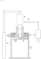
- FIG. 1 to FIG. 6 are drawings provided for describing a viscous material supply device according to the present disclosure.
- the viscous material supply device 100 is used for discharging and supplying viscous material.
- the viscous material supply device 100 applies grease, an adhesive, a liquid gasket such as an FIPG (Formed In Place Gasket), sealing material, or other viscous material, as an object to be applied, in a manufacturing process, maintenance and the like of a machine such as an automobile or industrial machine.
- a liquid gasket such as an FIPG (Formed In Place Gasket)
- sealing material or other viscous material
- the viscous material is viscous material that has fluidity but whose viscosity is relatively low and flow resistance to a pipeline and a nozzle is relatively low, and for example, includes grease, an adhesive, a liquid gasket such as FIPG, sealing material, and the like.
- a preferable viscosity of the viscous material is 200 Pa ⁇ s or less.
- the viscous material supply device 100 includes, as shown in FIGS. 1 and 2 , a tank 10, a piston 20, a covering sheet 30, a sealing member 40, a pump 50, an air cylinder 60, a dispenser 70, a pipeline 80, and an air bleeding valve 90.
- a tank 10 a tank 10
- a piston 20 a piston 20
- a covering sheet 30 a sealing member 40
- a pump 50 an air cylinder 60
- a dispenser 70 a pipeline 80
- an air bleeding valve 90 an air bleeding valve 90.
- the tank 10 has, as shown in FIG. 2 , a storage space 11 storing the viscous material.
- the tank 10 is a member formed in a cylindrical shape and made of plastic such as polyethylene, polypropylene, ethylene-vinyl acetate copolymer, polyethylene terephthalate, polyamide, or made of metal, and is constituted by having an upper part of the cylindrical shape opened so as to allow the viscous material to be accommodated.
- the shape of the tank 10 is not limited to a cylinder as long as the viscous material can be stored, and other than the above shape, can be formed in, for example, a shape of a polygonal column such as a square column or hexagonal column. Also, the shape is not necessarily cylinder or polygonal column, as long as the tank 10 is stably installed on the ground. In the present embodiment, the viscous material is directly accommodated in the tank 10 without interposing a bag or the like.
- the piston 20 is slidably inserted inside the tank 10.
- the piston 20 has, as shown in FIG. 2 , a main body part 21, a pressing surface 22, a suction passage 23, pins 24, a first outer shape part 25, a second outer shape part 26, and nuts 27.
- the main body part 21 has, as shown in FIG. 2 , a plate member 21a and a plate member 21b.
- the plate member 21a is constituted of a shape formed by combining a small-diameter cylinder and a large-diameter cylinder.
- the plate member 21b is constituted of a shape formed by combining a small-diameter cylinder and a large-diameter cylinder.
- the plate member 21a and the plate member 21b are integrally constituted by the pins 24 and the nuts 27.
- a specific shape of the main body part 21 is not limited to the above as long as the main body part 21 can be slidably inserted inside the tank 10 and can press the viscous material stored inside the tank 10.
- the first outer shape part 25 is, as shown in FIG. 2 , a portion of the small-diameter cylinder in the plate member 21b, whose outer diameter (outer shape) is constituted smaller than that of the second outer shape part 26.
- the second outer shape part 26 is a portion of the large-diameter cylinder in the plate member 21b, and is separated from the first outer shape part 25 downward in FIG. 2 in a direction that the piston 20 slides, and has an outer periphery constituted larger than the first outer shape part 25.
- the sealing member 40 having a disc shape is attached.
- the large-diameter portion of the cylinder in the plate member 21a and the second outer shape part 26 in the plate member 21b have outer diameters formed substantially the same as shown in FIG. 2 , however, the configuration is not limited to this.
- the pressing surface 22 is a portion that presses the viscous material in the piston 20. As shown in FIG. 2 , the pressing surface 22 refers to an end surface in an axial direction of the second outer shape part 26 in the plate member 21b of the main body part 21. The pressing surface 22 refers to a portion in the radial direction from the outer periphery of the second outer shape part 26 of the plate member 21b to an outer periphery of the suction passage 23, and is formed in a substantially disc shape.
- the suction passage 23 is a portion where the viscous material inside the tank 10 flows through by pressing by the pressing surface 22. As shown in FIG. 2 , the suction passage 23 is formed by hollowing out the main body part 21 at an axis center portion located at an inner part in the radial direction. In the present embodiment, the suction passage 23 has a substantially circular cross-sectional shape, however, the cross-sectional shape is not limited to the above as long as the viscous material can be flowed through.
- the pipeline 80 is connected to the piston 20, and the pipeline 80 communicates with the suction passage 23. The viscous material stored in the storage space 11 of the tank 10 flows into the suction passage 23 by pressing of the pressing surface 22, and thereafter, flows into the pipeline 80.
- the pins 24 are erected on a surface opposite to the pressing surface 22 in the axial direction of the piston 20 as shown in FIG. 2 , and the covering sheet 30 is attached to the piston 20.
- the pins 24 are erected with uniform angular intervals at four locations for every 90 degrees in a circumferential direction (angular direction), in plan view from the axial direction of the piston 20.
- numbers, locations to be attached, and the angular intervals of the pins 24 are not limited to the above as long as the covering sheet 30 can be attached to the piston 20, and the pins 24 are not necessarily arranged uniformly in the angular direction (circumferential direction).
- the pin 24 is formed with a screw portion and is screwed with the nut 27.
- the configuration is not limited to this, and as long as the covering sheet 30 can be attached to the piston 20, the screw portion and the nut 27 are not necessarily provided.
- the covering sheet 30 has, as shown in FIG. 2 and FIG. 3 , a covering part 31, a communication hole 32, and insertion holes 33.
- the covering part 31 covers the pressing surface 22 in the piston 20. More specifically, the covering part 31 covers the pressing surface 22 being an end surface in the axial direction of the second outer shape part 26 of the plate member 21b of the piston 20. With this configuration, the viscous material can be prevented from being adhered to the pressing surface 22 of the piston 20 after being force-fed from the tank 10, thereby facilitating removal operation of removing the viscous material from the piston 20.
- Material of the covering sheet 30 is not particularly limited, but polyethylene, polypropylene, and the like are exemplified.
- the communication hole 32 communicates with the suction passage 23 of the piston 20 when the covering sheet 30 is attached to the piston 20.
- the communication hole 32 is formed in a substantially circular shape similarly to the suction passage 23.
- the insertion holes 33 are provided at a relatively outer part in the radial direction of the covering sheet 30.
- the covering sheet 30 is, as shown in disclosed but not claimed FIGS. 4 and 5 , folded from a state of being located on a side of the pressing surface 22 to a state such that the outer periphery of the covering sheet 30 is on a side opposite to the pressing surface 22.
- the insertion holes 33 are fitted with the pins 24 of the piston 20 at portions of the covering sheet 30 being folded. With this configuration, axis centers of the suction passage 23 of the piston 20 and the communication hole 32 of the covering sheet 30 match with each other.
- the covering sheet 30 is formed in a substantially rectangular shape in plan view, however, the shape is not limited to the above as long as the pressing surface 22 of the piston 20 is covered, and apart from the above, may have a circular shape or the like.
- the sealing member 40 is formed in a cylindrical shape with a substantially disc-shaped cross-section, and is attached to the outer periphery of the first outer shape part 25 of the plate member 21b of the piston 20.
- the sealing member 40 seals a portion between the piston 20 and the tank 10 by being attached at the above position.
- Material of the sealing member 40 is not particularly limited as long as the portion between the piston 20 and the tank 10 can be sealed, but NBR (nitrile butadiene rubber), acrylic rubber, chloroprene rubber, fluoro-rubber, polyurethane, and the like are exemplified, and the material is selected according to the viscous material.
- the pump 50 is not particularly limited as long as the pump can force-feed the viscous material pushed out from the tank 10 to the dispenser 70 and the like, and for example, a gear pump, a plunger pump, a screw pump, a piston pump, and the like are exemplified.
- the air cylinder 60 is provided to drive the piston 20 from an opening part of the tank 10 toward a bottom part of the same by air pressure.
- the dispenser 70 is constituted of known components including a syringe, a plunger that can move within the syringe, and the like.
- the pipeline 80 is provided from the piston 20 through the pump 50 to the dispenser 70, and the viscous material flows through the pipeline 80.
- a cross-sectional shape of the pipeline 80 is formed in a substantially disc hollow shape, however, the shape is not limited to this.
- the air bleeding valve 90 switches opening/closing between the storage space 11 of the tank 10 and the outside in a state in which the piston 20 is inserted in the storage space 11 of the tank 10.
- FIG. 6 is a flowchart showing the viscous material supply method according to one embodiment of the present invention.
- the viscous material supply method generally, the tank 10, the piston 20, the covering sheet 30, and the like are prepared (ST1, 2).
- the covering sheet 30 is attached to the piston 20 (ST3).
- the viscous material is pressed by the pressing surface 22 of the piston 20 to force-feed the viscous material into the suction passage 23 (ST4).
- the attaching method of the covering sheet 30 includes, in ST2, ST3 of FIG. 6 , preparing the piston 20 and the covering sheet 30, and attaching the covering sheet 30 to the piston 20. The detailed description is made below.
- the components from the tank 10 through the air bleeding valve 90 required in supplying the viscous material are prepared (ST1, ST2). At this time, the tank 10 is filled with the viscous material in advance. Next, the sealing member 40 is attached to the piston 20.
- the covering sheet 30 is arranged on the side of the pressing surface 22 of the piston 20.
- an inner periphery in the covering part 31 is abutted to the pressing surface 22 of the piston 20, and portions opposing to each other at an outer periphery of the covering sheet 30 are folded back toward the side opposite to the pressing surface 22 with an outer peripheral edge part of the second outer shape part 26 of the piston 20 as an origin.
- the insertion holes 33 of the covering sheet 30 are fitted with the pins 24 of the piston 20.
- folded-back parts f1, f2 are formed as shown in FIG. 4 .
- the insertion holes 33 of the covering sheet 30 are fitted with the pins 24 of the piston 20.
- the suction passage 23 of the piston 20 and the communication hole 32 of the covering sheet 30 communicate with each other and the axis centers of the suction passage 23 and the communication hole 32 match with each other.
- “matching" of the suction passage 23 and the communication hole 32 herein allows to have positional shift of about 2, 3 mm.
- the piston 20 and the covering sheet 30 can be inserted into the tank 10 in this state.
- the folded-back parts f2 of the covering sheet 30 are positioned further outward in the radial direction than the sealing member 40. In other words, the sealing member 40 seals the tank 10 while having the covering sheet 30 interposed therebetween.
- the covering sheet 30 can be attached to the tank 10 in a state of having the folded-back parts f1, f2 formed, however, the following procedure can be taken following FIG. 4 . That is, as shown in disclosed but not claimed FIG. 5 following FIG. 4 , portions that have not been folded back at the outer periphery of the covering sheet 30 are folded back toward the side opposite to the pressing surface 22 with the outer peripheral edge part of the second outer shape part 26 of the piston 20 as an origin. Then, the insertion holes 33 of the covering sheet 30 which have not been fitted with the pins 24 in FIG. 4 are fitted with the pins 24 of the piston 20. Accordingly, folded-back parts f3, f4 are formed.
- the piston 20 When the covering sheet 30 is successfully attached to the piston 20, the piston 20, the air cylinder 60, the pump 50, and the dispenser 70 are connected. Thereafter, the piston 20 is driven by the air cylinder 60 and is pushed inside the storage space 11 of the tank 10, and the viscous material is flowed through the suction passage 23 and the pipeline 80 by activating the pump 50 and is supplied from the dispenser 70 (ST4).
- the covering sheet 30 is replaced with the new one (ST2). Then, the attaching of the covering sheet 30 to the piston 20 (ST3) and force-feeding of the viscous material (ST4) are repeated.
- the viscous material supply device 100 includes the tank 10, the piston 20, and the covering sheet 30.
- the tank 10 is provided with a storage space 11 storing the viscous material.
- the piston 20 is slidably inserted into the tank 10, and the piston 20 is provided with the pressing surface 22 that presses the viscous material, and a suction passage 23 through which the viscous material inside the tank 10 flows by pressing force of the pressing surface 22.
- the covering sheet 30 includes the covering part 31 that covers the pressing surface 22 in the piston 20, and the communication hole 32 that communicates with the suction passage 23.
- the tank 10, the piston 20, and the covering sheet 30 are prepared.
- the covering sheet 30 is attached to the piston 20 such that the covering part 31 of the covering sheet 30 covers the pressing surface 22 of the piston 20, and the communication hole 32 of the covering sheet 30 communicates with the suction passage 23 of the piston 20.
- the viscous material is pressed by the pressing surface 22 of the piston 20, and the viscous material is flowed through the suction passage 23.
- the covering sheet 30 is attached to the piston 20 such that the covering part 31 of the covering sheet 30 covers the pressing surface 22 of the piston 20 and the communication hole 32 of the covering sheet 30 communicates with the suction passage 23 of the piston 20.
- the pressing surface 22 of the piston 20 is covered by the covering part 31 of the covering sheet 30, preventing the viscous material to be adhered to the pressing surface 22, and correspondingly, the removal operation of the viscous material in the piston 20 can be facilitated.
- the pins 24 for attaching the covering sheet 30 to the piston 20 are erected on the surface on the side opposite to the pressing surface 22.
- the covering sheet 30 includes the insertion holes 33 that are fitted with, when outer portions of the covering part 31 are folded back toward the side opposite to the pressing surface 22, the pins 24 at the folded back portions.
- the covering sheet 30 is arranged on the side of the pressing surface 22 of the piston 20, and an inner part (inner side) of the covering sheet 30 is abutted to the pressing surface 22 of the piston 20.
- the outer parts (outer sides) of the covering part 31 are folded back to the side opposite to the side of the pressing surface 22 of the piston 20, and the insertion holes 33 are fitted with the pins 24 of the piston 20.
- the insertion holes 33 with the pins 24 of the piston 20
- the axis centers of the suction passage 23 and the communication hole 32 of the covering sheet 30 match with each other.
- FIG. 7 is a cross-sectional view according to a disclosed but not claimed comparative example similar to FIG. 2 .
- a suction passage and a communication hole are aligned with each other in a state where pins 24 are not provided in the piston 20 and a covering sheet S does not have insertion holes
- an operator needs to visually align an axis center CL1 of the suction passage and an axis center CL2 of the communication hole.
- the viscous material supply device 100 of the present embodiment is configured as described above, therefore, the aligning of the suction passage 23 and the communication hole 32 can be simplified. Moreover, accuracy of the aligning can be improved as compared to that performed visually.
- the suction passage 23 may be at least partially covered by the covering sheet 30 to obstruct the force-feeding of the viscous material, causing a risk that the viscous material remains in the storage space 11 of the tank 10.
- the above situation can be prevented and the risk of the viscous material remaining in the storage space 11 can be suppressed or reduced.
- the sealing member 40 for sealing the portion between the piston 20 and the tank 10 is attached at the outer periphery of the first outer shape part 25 of the piston 20.
- the sealing member 40 is attached to an outer part of the first outer shape part 25 in the radial direction of the piston 20 before the viscous material is flowed through the suction passage 23 by the pressing surface 22 of the piston 20. Accordingly, when the viscous material inside the tank 10 is pressed by the piston 20, leaking of the viscous material from the outer periphery of the piston 20 can be prevented.
- FIG. 8 is a partial enlarged view showing a disclosed but not claimed modified example of FIG. 2 .
- the outer periphery of the covering sheet 30 is folded back toward the side opposite to the pressing surface 22, and the insertion holes 33 are fitted with the pins 24, however, the configuration is not limited to this.
- an edge part of the insertion hole 33 in the covering sheet 30 may be provided with, as shown in FIG. 8 , a reinforcing member 34 for increasing a thickness at the edge part of the insertion hole 33.
- the reinforcing member 34 is applied with an adhesive on a side facing (side coming into contact with) the covering sheet 30, and thereby, is constituted integrally with the covering sheet 30.
- an outside surface 41 of the sealing member 40 is positioned further outward in the radial direction than the covering sheet 30 attached to the piston 20 at the first outer shape part 25.
- the outside surface 41 of the sealing member 40 is positioned further outward in the radial direction than the covering sheet 30 at the first outer shape part 25.
- the covering sheet 30 is attached to the piston 20 before the sealing member 40 is attached to the piston 20. That is, the covering sheet 30 is arranged on the side of the pressing surface 22, the inner periphery of the covering part 31 is abutted to the pressing surface 22, and the outer periphery of the covering part 31 is folded back to the side opposite to the pressing surface 22 with the outer peripheral edge part of the second outer shape part 26 of the piston 20 as an origin. Thereafter, the insertion holes 33 are fitted with the pins 24. Accordingly, the axis centers of the suction passage 23 and the communication hole 32 match with each other. The sealing member 40 is then attached to the piston 20.
- the sealing member 40 is positioned on the outer periphery further than the covering sheet 30 at the first outer shape part 25, allowing the sealing member 40 to come into contact with the tank 10 without interposing the covering sheet 30. Accordingly, a portion between the piston 20 and the tank 10 can be more firmly sealed.
- the configuration is not limited to this.
- a bag that accommodates the viscous material may be accommodated together in the storage space 11 of the tank 10.
Landscapes
- Engineering & Computer Science (AREA)
- Mechanical Engineering (AREA)
- General Engineering & Computer Science (AREA)
- Coating Apparatus (AREA)
- Reciprocating Pumps (AREA)
- Containers And Packaging Bodies Having A Special Means To Remove Contents (AREA)
- Details Of Reciprocating Pumps (AREA)
Description
- The present invention relates to a viscous material supply device and a viscous material supply method.
- For example, in various machines such as automobiles and industrial machines, a device for ejecting a constant amount of viscous material from a nozzle of a dispenser and applying the viscous material on a predetermined portion is used in applying viscous material such as an adhesive or sealing material. In the device as such, there is installed a platen (hereinafter, referred to as a piston) which presses a container accommodating the viscous material and is provided with a flow passage for sucking the viscous material. Here, a technique is disclosed in which the piston is moved, and the viscous material is force-fed from the flow passage connected to the piston (refer to Patent Literature 1).
- Patent Literature 1:
JP H11-156282 A -
DE 10 2004 016006 A1 relates to a container for a product.US 2007/039978 A1 relates to an emptying device.DE 10 2007 003972 A1 relates to a device for air bubble-free extraction and improved aeration. - In the above application device, the viscous material needs to be supplemented when all of the viscous material inside the container is finished to be force-fed. At this time, the piston is temporarily removed from the container. In supplementing the viscous material into the container, because the viscous material that had been force-fed from the previously used container is adhered on the piston, the viscous material adhered to the piston needs to be removed when the container is replaced to the new one. Regarding this point, the inventor has been intensively studying to improve an efficiency of removal operation of the viscous material that could be adhered to the piston.
- Accordingly, an object of the present invention is to provide a viscous material supply device and a viscous material supply method that facilitate the removal operation of the viscous material that could be adhered to the piston.
- The viscous material supply device according to an aspect of the present invention to solve the above problem includes a tank, a piston, and a covering sheet. The tank includes a storage space storing viscous material. The piston is slidably inserted into the tank, and the piston is provided with a pressing surface that presses the viscous material and a suction passage through which the viscous material inside the tank flows by pressing force of the pressing surface. The covering sheet includes a covering part covering the pressing surface in the piston and a communication hole communicating with the suction passage. Further, one aspect of the present invention is the covering sheet used in the viscous material supply device, and including the covering part that covers the pressing surface in the piston and the communication hole that communicates with the suction passage.
- In the viscous material supply method according to one aspect of the present invention, the tank, the piston, and the covering sheet are prepared. Next, the covering sheet is attached to the piston such that the covering part of the covering sheet covers the pressing surface of the piston and the communication hole of the covering sheet communicates with the suction passage of the piston. Thereafter, the viscous material is pressed by the pressing surface of the piston, and the viscous material is flowed through the suction passage. Further, one aspect of the present invention is an attaching method of the covering sheet. In the method, there are prepared the piston in which the pressing surface and the suction passage are provided, and the covering sheet including the covering part and the communication hole. Then, the covering sheet is attached to the piston such that the covering part of the covering sheet covers the pressing surface of the piston and the communication hole of the covering sheet communicates with the suction passage of the piston.
-
-
FIG. 1 is a perspective view showing a viscous material supply device according to one disclosed but not claimed embodiment of the present invention. -
FIG. 2 is a cross-sectional view showing the viscous material supply device. -
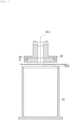
FIG. 3 is a perspective view showing a disclosed but not claimed case of attaching a covering sheet to a piston. -
FIG. 4 is a perspective view showing, in continuation ofFIG. 3 , the disclosed but not claimed case of attaching the covering sheet to the piston. -
FIG. 5 shows a disclosed but not claimed modified example of the embodiment and is a perspective view showing, in continuation ofFIG. 4 , the case of attaching the covering sheet to the piston. -
FIG. 6 is a flowchart showing a viscous material supply method according to one embodiment of the present invention. -
FIG. 7 is a cross-sectional view according to a disclosed but not claimed comparative example ofFIG. 2 . -
FIG. 8 is a partial enlarged view showing a vicinity of an outer periphery of the disclosed but not claimed piston in the cross-sectional view ofFIG. 2 and showing a modified example ofFIG. 2 . -
FIG. 9 is a partial enlarged view showing the vicinity of the outer periphery of the piston according to the invention in the cross-sectional view ofFIG. 2 and showing the modified example ofFIG. 2 . - Hereinafter, an embodiment of the present invention is described with reference to the attached drawings. Note that the following description does not limit the technical scope and the meaning of the term recited in claims. Moreover, dimensional proportions in the drawings are exaggerated for convenience of description, and may differ from the actual proportion.
-
FIG. 1 to FIG. 6 are drawings provided for describing a viscous material supply device according to the present disclosure. - The viscous
material supply device 100 according to the present disclosure is used for discharging and supplying viscous material. The viscousmaterial supply device 100 applies grease, an adhesive, a liquid gasket such as an FIPG (Formed In Place Gasket), sealing material, or other viscous material, as an object to be applied, in a manufacturing process, maintenance and the like of a machine such as an automobile or industrial machine. - Here, the viscous material is viscous material that has fluidity but whose viscosity is relatively low and flow resistance to a pipeline and a nozzle is relatively low, and for example, includes grease, an adhesive, a liquid gasket such as FIPG, sealing material, and the like. A preferable viscosity of the viscous material is 200 Pa·s or less. In the following description, a case is described in which a silicone-based gasket that is moisture-cured by a condensation reaction in the atmosphere is used as an example of the viscous material. However, the present invention is not limited to the above.
- The viscous
material supply device 100 according to the present disclosure includes, as shown inFIGS. 1 and2 , atank 10, apiston 20, acovering sheet 30, a sealingmember 40, apump 50, anair cylinder 60, adispenser 70, apipeline 80, and anair bleeding valve 90. The detailed description is made below. - The
tank 10 has, as shown inFIG. 2 , astorage space 11 storing the viscous material. Thetank 10 is a member formed in a cylindrical shape and made of plastic such as polyethylene, polypropylene, ethylene-vinyl acetate copolymer, polyethylene terephthalate, polyamide, or made of metal, and is constituted by having an upper part of the cylindrical shape opened so as to allow the viscous material to be accommodated. However, the shape of thetank 10 is not limited to a cylinder as long as the viscous material can be stored, and other than the above shape, can be formed in, for example, a shape of a polygonal column such as a square column or hexagonal column. Also, the shape is not necessarily cylinder or polygonal column, as long as thetank 10 is stably installed on the ground. In the present embodiment, the viscous material is directly accommodated in thetank 10 without interposing a bag or the like. - The
piston 20 is slidably inserted inside thetank 10. Thepiston 20 has, as shown inFIG. 2 , amain body part 21, apressing surface 22, asuction passage 23,pins 24, a firstouter shape part 25, a secondouter shape part 26, and nuts 27. - The
main body part 21 has, as shown inFIG. 2 , aplate member 21a and a plate member 21b. Theplate member 21a is constituted of a shape formed by combining a small-diameter cylinder and a large-diameter cylinder. Although different in sizes, similarly to theplate member 21a, the plate member 21b is constituted of a shape formed by combining a small-diameter cylinder and a large-diameter cylinder. Theplate member 21a and the plate member 21b are integrally constituted by thepins 24 and the nuts 27. However, a specific shape of themain body part 21 is not limited to the above as long as themain body part 21 can be slidably inserted inside thetank 10 and can press the viscous material stored inside thetank 10. - The first
outer shape part 25 is, as shown inFIG. 2 , a portion of the small-diameter cylinder in the plate member 21b, whose outer diameter (outer shape) is constituted smaller than that of the secondouter shape part 26. The secondouter shape part 26 is a portion of the large-diameter cylinder in the plate member 21b, and is separated from the firstouter shape part 25 downward inFIG. 2 in a direction that thepiston 20 slides, and has an outer periphery constituted larger than the firstouter shape part 25. On an outer periphery of the firstouter shape part 25, the sealingmember 40 having a disc shape is attached. The large-diameter portion of the cylinder in theplate member 21a and the secondouter shape part 26 in the plate member 21b have outer diameters formed substantially the same as shown inFIG. 2 , however, the configuration is not limited to this. - The
pressing surface 22 is a portion that presses the viscous material in thepiston 20. As shown inFIG. 2 , thepressing surface 22 refers to an end surface in an axial direction of the secondouter shape part 26 in the plate member 21b of themain body part 21. Thepressing surface 22 refers to a portion in the radial direction from the outer periphery of the secondouter shape part 26 of the plate member 21b to an outer periphery of thesuction passage 23, and is formed in a substantially disc shape. - The
suction passage 23 is a portion where the viscous material inside thetank 10 flows through by pressing by thepressing surface 22. As shown inFIG. 2 , thesuction passage 23 is formed by hollowing out themain body part 21 at an axis center portion located at an inner part in the radial direction. In the present embodiment, thesuction passage 23 has a substantially circular cross-sectional shape, however, the cross-sectional shape is not limited to the above as long as the viscous material can be flowed through. Thepipeline 80 is connected to thepiston 20, and thepipeline 80 communicates with thesuction passage 23. The viscous material stored in thestorage space 11 of thetank 10 flows into thesuction passage 23 by pressing of thepressing surface 22, and thereafter, flows into thepipeline 80. - The
pins 24 are erected on a surface opposite to thepressing surface 22 in the axial direction of thepiston 20 as shown inFIG. 2 , and the coveringsheet 30 is attached to thepiston 20. In the present embodiment, thepins 24 are erected with uniform angular intervals at four locations for every 90 degrees in a circumferential direction (angular direction), in plan view from the axial direction of thepiston 20. However, numbers, locations to be attached, and the angular intervals of thepins 24 are not limited to the above as long as the coveringsheet 30 can be attached to thepiston 20, and thepins 24 are not necessarily arranged uniformly in the angular direction (circumferential direction). Additionally, thepin 24 is formed with a screw portion and is screwed with the nut 27. However, the configuration is not limited to this, and as long as the coveringsheet 30 can be attached to thepiston 20, the screw portion and the nut 27 are not necessarily provided. - The covering
sheet 30 has, as shown inFIG. 2 andFIG. 3 , a coveringpart 31, acommunication hole 32, and insertion holes 33. - The covering
part 31 covers thepressing surface 22 in thepiston 20. More specifically, the coveringpart 31 covers thepressing surface 22 being an end surface in the axial direction of the secondouter shape part 26 of the plate member 21b of thepiston 20. With this configuration, the viscous material can be prevented from being adhered to thepressing surface 22 of thepiston 20 after being force-fed from thetank 10, thereby facilitating removal operation of removing the viscous material from thepiston 20. Material of the coveringsheet 30 is not particularly limited, but polyethylene, polypropylene, and the like are exemplified. - The
communication hole 32 communicates with thesuction passage 23 of thepiston 20 when the coveringsheet 30 is attached to thepiston 20. Thecommunication hole 32 is formed in a substantially circular shape similarly to thesuction passage 23. - The insertion holes 33 are provided at a relatively outer part in the radial direction of the covering
sheet 30. The coveringsheet 30 is, as shown in disclosed but not claimedFIGS. 4 and 5 , folded from a state of being located on a side of thepressing surface 22 to a state such that the outer periphery of the coveringsheet 30 is on a side opposite to thepressing surface 22. The insertion holes 33 are fitted with thepins 24 of thepiston 20 at portions of the coveringsheet 30 being folded. With this configuration, axis centers of thesuction passage 23 of thepiston 20 and thecommunication hole 32 of the coveringsheet 30 match with each other. - The covering
sheet 30 is formed in a substantially rectangular shape in plan view, however, the shape is not limited to the above as long as thepressing surface 22 of thepiston 20 is covered, and apart from the above, may have a circular shape or the like. - The sealing
member 40 is formed in a cylindrical shape with a substantially disc-shaped cross-section, and is attached to the outer periphery of the firstouter shape part 25 of the plate member 21b of thepiston 20. The sealingmember 40 seals a portion between thepiston 20 and thetank 10 by being attached at the above position. Material of the sealingmember 40 is not particularly limited as long as the portion between thepiston 20 and thetank 10 can be sealed, but NBR (nitrile butadiene rubber), acrylic rubber, chloroprene rubber, fluoro-rubber, polyurethane, and the like are exemplified, and the material is selected according to the viscous material. - The
pump 50 is not particularly limited as long as the pump can force-feed the viscous material pushed out from thetank 10 to thedispenser 70 and the like, and for example, a gear pump, a plunger pump, a screw pump, a piston pump, and the like are exemplified. - The
air cylinder 60 is provided to drive thepiston 20 from an opening part of thetank 10 toward a bottom part of the same by air pressure. Thedispenser 70 is constituted of known components including a syringe, a plunger that can move within the syringe, and the like. - The
pipeline 80 is provided from thepiston 20 through thepump 50 to thedispenser 70, and the viscous material flows through thepipeline 80. A cross-sectional shape of thepipeline 80 is formed in a substantially disc hollow shape, however, the shape is not limited to this. Theair bleeding valve 90 switches opening/closing between thestorage space 11 of thetank 10 and the outside in a state in which thepiston 20 is inserted in thestorage space 11 of thetank 10. - Next, a viscous material supply method and an attaching method of covering
sheet 30 are described.FIG. 6 is a flowchart showing the viscous material supply method according to one embodiment of the present invention. In the viscous material supply method, generally, thetank 10, thepiston 20, the coveringsheet 30, and the like are prepared (ST1, 2). Next, the coveringsheet 30 is attached to the piston 20 (ST3). Thereafter, the viscous material is pressed by thepressing surface 22 of thepiston 20 to force-feed the viscous material into the suction passage 23 (ST4). Further, the attaching method of the coveringsheet 30 includes, in ST2, ST3 ofFIG. 6 , preparing thepiston 20 and the coveringsheet 30, and attaching the coveringsheet 30 to thepiston 20. The detailed description is made below. - First, the components from the
tank 10 through theair bleeding valve 90 required in supplying the viscous material are prepared (ST1, ST2). At this time, thetank 10 is filled with the viscous material in advance. Next, the sealingmember 40 is attached to thepiston 20. - Next, as shown in disclosed but not claimed
FIG. 3 , the coveringsheet 30 is arranged on the side of thepressing surface 22 of thepiston 20. Then, as shown in disclosed but not claimedFIG. 4 , an inner periphery in the coveringpart 31 is abutted to thepressing surface 22 of thepiston 20, and portions opposing to each other at an outer periphery of the coveringsheet 30 are folded back toward the side opposite to thepressing surface 22 with an outer peripheral edge part of the secondouter shape part 26 of thepiston 20 as an origin. Then, the insertion holes 33 of the coveringsheet 30 are fitted with thepins 24 of thepiston 20. - Accordingly, folded-back parts f1, f2 are formed as shown in
FIG. 4 . Next, the insertion holes 33 of the coveringsheet 30 are fitted with thepins 24 of thepiston 20. Accordingly, thesuction passage 23 of thepiston 20 and thecommunication hole 32 of the coveringsheet 30 communicate with each other and the axis centers of thesuction passage 23 and thecommunication hole 32 match with each other. Note that "matching" of thesuction passage 23 and thecommunication hole 32 herein allows to have positional shift of about 2, 3 mm. Thepiston 20 and the coveringsheet 30 can be inserted into thetank 10 in this state. Also, in this disclosed but not claimed state, the folded-back parts f2 of the coveringsheet 30 are positioned further outward in the radial direction than the sealingmember 40. In other words, the sealingmember 40 seals thetank 10 while having the coveringsheet 30 interposed therebetween. - Note that the covering
sheet 30 can be attached to thetank 10 in a state of having the folded-back parts f1, f2 formed, however, the following procedure can be taken followingFIG. 4 . That is, as shown in disclosed but not claimedFIG. 5 followingFIG. 4 , portions that have not been folded back at the outer periphery of the coveringsheet 30 are folded back toward the side opposite to thepressing surface 22 with the outer peripheral edge part of the secondouter shape part 26 of thepiston 20 as an origin. Then, the insertion holes 33 of the coveringsheet 30 which have not been fitted with thepins 24 inFIG. 4 are fitted with thepins 24 of thepiston 20. Accordingly, folded-back parts f3, f4 are formed. - When the covering
sheet 30 is successfully attached to thepiston 20, thepiston 20, theair cylinder 60, thepump 50, and thedispenser 70 are connected. Thereafter, thepiston 20 is driven by theair cylinder 60 and is pushed inside thestorage space 11 of thetank 10, and the viscous material is flowed through thesuction passage 23 and thepipeline 80 by activating thepump 50 and is supplied from the dispenser 70 (ST4). - Here, when the viscous material becomes short in supply (ST5: YES), operations of the
pump 50 and theair cylinder 60 are stopped and the supply of the viscous material is stopped (ST6). Then, thepiston 20 is pulled out from the tank 10 (ST7). Further, thepump 50 and thepiston 20 are separated, and the coveringsheet 30 is removed from thepiston 20. Because the viscous material is adhered to thesuction passage 23 of thepiston 20, cleaning is performed (ST8). Thepressing surface 22 of thepiston 20 is covered by the coveringpart 31 of the coveringsheet 30, therefore, does not require cleaning, and the cleaning operation is correspondingly facilitated. Next, thetank 10 is replaced with the new one having the viscous material therein (ST9). - When the cleaning of the
piston 20 and the replacement of thetank 10 are finished, the coveringsheet 30 is replaced with the new one (ST2). Then, the attaching of the coveringsheet 30 to the piston 20 (ST3) and force-feeding of the viscous material (ST4) are repeated. - When the viscous material is not short in supply in the
storage space 11 of the tank 10 (ST5: NO), and a required amount of the viscous material has not been supplied (ST10: NO), the supply of the viscous material is continued (ST4). - As described above, the viscous
material supply device 100 according to the present embodiment includes thetank 10, thepiston 20, and the coveringsheet 30. Thetank 10 is provided with astorage space 11 storing the viscous material. Thepiston 20 is slidably inserted into thetank 10, and thepiston 20 is provided with thepressing surface 22 that presses the viscous material, and asuction passage 23 through which the viscous material inside thetank 10 flows by pressing force of thepressing surface 22. The coveringsheet 30 includes the coveringpart 31 that covers thepressing surface 22 in thepiston 20, and thecommunication hole 32 that communicates with thesuction passage 23. - Further, in the viscous material supply method according to the present embodiment, the
tank 10, thepiston 20, and the coveringsheet 30 are prepared. Next, the coveringsheet 30 is attached to thepiston 20 such that the coveringpart 31 of the coveringsheet 30 covers thepressing surface 22 of thepiston 20, and thecommunication hole 32 of the coveringsheet 30 communicates with thesuction passage 23 of thepiston 20. Thereafter, the viscous material is pressed by thepressing surface 22 of thepiston 20, and the viscous material is flowed through thesuction passage 23. Further, in the attaching method of the coveringsheet 30 to thepiston 20, thepiston 20 and the coveringsheet 30 are prepared. Then, the coveringsheet 30 is attached to thepiston 20 such that the coveringpart 31 of the coveringsheet 30 covers thepressing surface 22 of thepiston 20 and thecommunication hole 32 of the coveringsheet 30 communicates with thesuction passage 23 of thepiston 20. - Accordingly, the
pressing surface 22 of thepiston 20 is covered by the coveringpart 31 of the coveringsheet 30, preventing the viscous material to be adhered to thepressing surface 22, and correspondingly, the removal operation of the viscous material in thepiston 20 can be facilitated. - Additionally, in the
piston 20, thepins 24 for attaching the coveringsheet 30 to thepiston 20 are erected on the surface on the side opposite to thepressing surface 22. The coveringsheet 30 includes the insertion holes 33 that are fitted with, when outer portions of the coveringpart 31 are folded back toward the side opposite to thepressing surface 22, thepins 24 at the folded back portions. The coveringsheet 30 is arranged on the side of thepressing surface 22 of thepiston 20, and an inner part (inner side) of the coveringsheet 30 is abutted to thepressing surface 22 of thepiston 20. The outer parts (outer sides) of the coveringpart 31 are folded back to the side opposite to the side of thepressing surface 22 of thepiston 20, and the insertion holes 33 are fitted with thepins 24 of thepiston 20. As described above, by fitting the insertion holes 33 with thepins 24 of thepiston 20, the axis centers of thesuction passage 23 and thecommunication hole 32 of the coveringsheet 30 match with each other. -
FIG. 7 is a cross-sectional view according to a disclosed but not claimed comparative example similar toFIG. 2 . As in a case of the comparative example ofFIG. 7 , in a case in which a suction passage and a communication hole are aligned with each other in a state where pins 24 are not provided in thepiston 20 and a covering sheet S does not have insertion holes, an operator needs to visually align an axis center CL1 of the suction passage and an axis center CL2 of the communication hole. On the other hand, the viscousmaterial supply device 100 of the present embodiment is configured as described above, therefore, the aligning of thesuction passage 23 and thecommunication hole 32 can be simplified. Moreover, accuracy of the aligning can be improved as compared to that performed visually. Further, when the axis centers of thecommunication hole 32 of the coveringsheet 30 and thesuction passage 23 do not match with each other, thesuction passage 23 may be at least partially covered by the coveringsheet 30 to obstruct the force-feeding of the viscous material, causing a risk that the viscous material remains in thestorage space 11 of thetank 10. On the other hand, by matching the axis centers of thecommunication hole 32 and thesuction passage 23 by thepins 24 and the insertion holes 33 as described above, the above situation can be prevented and the risk of the viscous material remaining in thestorage space 11 can be suppressed or reduced. - Additionally, the sealing
member 40 for sealing the portion between thepiston 20 and thetank 10 is attached at the outer periphery of the firstouter shape part 25 of thepiston 20. The sealingmember 40 is attached to an outer part of the firstouter shape part 25 in the radial direction of thepiston 20 before the viscous material is flowed through thesuction passage 23 by thepressing surface 22 of thepiston 20. Accordingly, when the viscous material inside thetank 10 is pressed by thepiston 20, leaking of the viscous material from the outer periphery of thepiston 20 can be prevented. - Note that various changes can be made within the scope of the claims.
FIG. 8 is a partial enlarged view showing a disclosed but not claimed modified example ofFIG. 2 . In the above, it has been described that the outer periphery of the coveringsheet 30 is folded back toward the side opposite to thepressing surface 22, and the insertion holes 33 are fitted with thepins 24, however, the configuration is not limited to this. - Apart from the above, an edge part of the
insertion hole 33 in thecovering sheet 30 may be provided with, as shown inFIG. 8 , a reinforcingmember 34 for increasing a thickness at the edge part of theinsertion hole 33. The reinforcingmember 34 is applied with an adhesive on a side facing (side coming into contact with) thecovering sheet 30, and thereby, is constituted integrally with the coveringsheet 30. With this configuration, when tension is applied in thecovering sheet 30 at thepressing surface 22 and the side opposite thereto, deformation of the outer peripheral edge part of theinsertion hole 33 and moreover, positional shift of thecommunication hole 32 can be prevented. - Further, the disclosed but not claimed embodiment is described in which, in the above, the sealing
member 40 seals thetank 10 while having the coveringsheet 30 interposed therebetween, however, the configuration is not limited to this. According to the single embodiment of the claimed invention, as shown inFIG. 9 as well, anoutside surface 41 of the sealingmember 40 is positioned further outward in the radial direction than the coveringsheet 30 attached to thepiston 20 at the firstouter shape part 25. In this case, when attaching the sealingmember 40 to thepiston 20, theoutside surface 41 of the sealingmember 40 is positioned further outward in the radial direction than the coveringsheet 30 at the firstouter shape part 25. - The covering
sheet 30 is attached to thepiston 20 before the sealingmember 40 is attached to thepiston 20. That is, the coveringsheet 30 is arranged on the side of thepressing surface 22, the inner periphery of the coveringpart 31 is abutted to thepressing surface 22, and the outer periphery of the coveringpart 31 is folded back to the side opposite to thepressing surface 22 with the outer peripheral edge part of the secondouter shape part 26 of thepiston 20 as an origin. Thereafter, the insertion holes 33 are fitted with thepins 24. Accordingly, the axis centers of thesuction passage 23 and thecommunication hole 32 match with each other. The sealingmember 40 is then attached to thepiston 20. - With this configuration, the sealing
member 40 is positioned on the outer periphery further than the coveringsheet 30 at the firstouter shape part 25, allowing the sealingmember 40 to come into contact with thetank 10 without interposing the coveringsheet 30. Accordingly, a portion between thepiston 20 and thetank 10 can be more firmly sealed. - Further, the embodiment in which the viscous material is directly filled in the
storage space 11 of thetank 10 has been described above, however, the configuration is not limited to this. Apart from the above, not only the viscous material but also a bag that accommodates the viscous material may be accommodated together in thestorage space 11 of thetank 10. - Note that the present application is based on
Japanese Patent Application No. 2017-037247 filed on February 28, 2017 -
- 10
- tank
- 100
- viscous material supply device
- 20
- piston
- 22
- pressing surface
- 23
- suction passage
- 24
- pin
- 25
- first outer shape part
- 26
- second outer shape part
- 30
- covering sheet
- 31
- covering part
- 32
- communication hole
- 33
- insertion hole
- 34
- reinforcing member
- 40
- sealing member
- 41
- outside surface
- 50
- pump
Claims (3)
- A viscous material supply device (100) comprising:a tank (10) provided with a storage space (11) storing viscous material;a piston (20) slidably inserted into the tank, and is provided with a pressing surface (22) that presses the viscous material and a suction passage (23) through which the viscous material inside the tank flows by pressing force of the pressing surface;a covering sheet (30) including a covering part (31) covering the pressing surface in the piston and a communication hole (32) communicating with the suction passage;a sealing member (40) attached to an outer periphery of the piston and sealing a portion between the piston and the tank;characterized by covering sheet comprising a folded back portion (f1, f3) at which the covering sheet is folded back at an outer periphery towards a side of the piston opposite to the pressing surface, wherein the folded back portion includes insertion holes (33); andpins (24) erected on the side opposite to the pressing surface in the piston, wherein the insertion holes of the covering sheet are fitted with the pins to attach the covering sheet to the piston;wherein the insertion holes are fitted with the pins and wherein axis centers of the suction passage and the communication hole are matched with each other;the piston further includes a first outer shape part (25) on which the sealing member is attached and a second outer shape part (26) separated from the first outer shape part in a direction that the piston slides and whose outer periphery is formed larger than the first outer shape part, andthe sealing member has an outside surface (41) positioned further outward in a radial direction than the covering sheet attached to the piston, at least in the first outer shape part.
- The viscous material supply device (100) according to claim 1, wherein the insertion hole (33) is provided with a reinforcing member (34) increasing a thickness of an edge part of the insertion hole.
- A viscous material supply method comprising:preparing a tank (10) provided with a storage space (11) storing viscous material, a piston (20) slidably inserted into the tank, the piston provided with a pressing surface (22) configured to press the viscous material and a suction passage (23) through which the viscous material inside the tank flows by pressing force of the pressing surface, and a covering sheet (30) including a covering part (31) covering the pressing surface in the piston and a communication hole (32) communicating with the suction passage;attaching the covering sheet to the piston such that the covering part of the covering sheet covers the pressing surface of the piston and the communication hole of the covering sheet communicates with the suction passage of the piston;attaching a sealing member (40) that seals a portion between the piston and the tank outward in a radial direction of the piston to the piston before the viscous material is flowed through the suction passage by the pressing surface of the piston; andpressing the viscous material by the pressing surface of the piston, and flowing the viscous material through the suction passage,characterized in that pins (24) are erected on a side opposite to the pressing surface in the piston, and the covering sheet is provided with insertion holes (33),the method comprising, when attaching the covering sheet to the piston:arranging the covering sheet on a side of the pressing surface of the piston;abutting an inner part in the covering part of the covering sheet to the pressing surface of the piston;folding back outer parts in the covering part of the covering sheet to the side opposite to the pressing surface of the piston; andfitting the insertion holes of the covering sheet with the pins,wherein the piston is provided with a first outer shape part (25) on which the sealing member is attached, and a second outer shape part (26) separated from the first outer shape part in a direction that the piston slides and whose outer periphery is formed larger than the first outer shape part, the method further comprising:
when the sealing member is attached to the piston, positioning an outside surface (41) of the sealing member further outward in the radial direction than the covering sheet at least at the first outer shape part.
Applications Claiming Priority (2)
| Application Number | Priority Date | Filing Date | Title |
|---|---|---|---|
| JP2017037247 | 2017-02-28 | ||
| PCT/JP2017/042942 WO2018159043A1 (en) | 2017-02-28 | 2017-11-30 | Viscous material supply device, cover sheet used in viscous material supply device, viscous material supply method, and method for attaching cover sheet |
Publications (3)
| Publication Number | Publication Date |
|---|---|
| EP3590609A1 EP3590609A1 (en) | 2020-01-08 |
| EP3590609A4 EP3590609A4 (en) | 2020-03-04 |
| EP3590609B1 true EP3590609B1 (en) | 2025-02-12 |
Family
ID=63370802
Family Applications (1)
| Application Number | Title | Priority Date | Filing Date |
|---|---|---|---|
| EP17898451.4A Active EP3590609B1 (en) | 2017-02-28 | 2017-11-30 | Device and method for supplying viscous material |
Country Status (6)
| Country | Link |
|---|---|
| US (1) | US11480164B2 (en) |
| EP (1) | EP3590609B1 (en) |
| JP (1) | JP6974763B2 (en) |
| KR (1) | KR102350299B1 (en) |
| CN (1) | CN110267745B (en) |
| WO (1) | WO2018159043A1 (en) |
Families Citing this family (5)
| Publication number | Priority date | Publication date | Assignee | Title |
|---|---|---|---|---|
| WO2018041628A1 (en) | 2016-09-05 | 2018-03-08 | Sca Schucker Gmbh & Co. Kg | Barrel pump having a follower plate with an adjustable sealing ring |
| DE102017100712A1 (en) * | 2017-01-16 | 2018-07-19 | Atlas Copco Ias Gmbh | Apparatus and method for conveying viscous material |
| DE102020127440A1 (en) * | 2020-08-06 | 2022-02-10 | Atlas Copco Ias Gmbh | Device for conveying viscous material |
| DE102022135037A1 (en) * | 2022-12-30 | 2024-07-11 | Dosmatix Gmbh | Protective cap, barrel follower plate and barrel emptying device |
| DE102022135039A1 (en) * | 2022-12-30 | 2024-07-11 | Dosmatix Gmbh | Barrel follower for a barrel emptying device and barrel emptying device |
Citations (7)
| Publication number | Priority date | Publication date | Assignee | Title |
|---|---|---|---|---|
| US1341652A (en) * | 1918-06-21 | 1920-06-01 | Frederick K Lawrence | Grease-cup filler |
| US1689360A (en) * | 1926-07-20 | 1928-10-30 | Monnot Robert | Grease-gun-filling device |
| FR648014A (en) * | 1927-05-28 | 1928-12-04 | Device for drawing from containers containing certain liquids, such as paint, etc. | |
| US2768661A (en) * | 1953-03-27 | 1956-10-30 | Floyd W Tyler | Filling device for grease guns |
| US2811991A (en) * | 1954-06-07 | 1957-11-05 | Switzer Murt | Grease gun charging machines |
| FR2750961A1 (en) * | 1996-07-15 | 1998-01-16 | Aubert Guy | ASEPTIC AND INTERCHANGEABLE PISTON HEAD |
| US20110064587A1 (en) * | 2009-09-17 | 2011-03-17 | Nordson Corporation | Low waste pump follower |
Family Cites Families (17)
| Publication number | Priority date | Publication date | Assignee | Title |
|---|---|---|---|---|
| JPH0125666Y2 (en) * | 1984-10-06 | 1989-08-01 | ||
| KR890005050Y1 (en) * | 1985-10-07 | 1989-07-31 | 가부시기가이샤 스리본드 | Material supply equipment for viscous fluid pressure feed system |
| JPH04943Y2 (en) * | 1987-08-28 | 1992-01-13 | ||
| DE3904606A1 (en) * | 1989-02-16 | 1990-08-30 | Knieriem Guenther Dipl Ing Fh | Emptying device |
| JPH0751173Y2 (en) * | 1989-10-11 | 1995-11-22 | ファインコントロール株式会社 | plate |
| US5117998A (en) * | 1991-10-07 | 1992-06-02 | Graco Inc. | Universal five gallon wiper plate assembly |
| JP4035742B2 (en) | 1997-11-27 | 2008-01-23 | ノードソン株式会社 | Method and apparatus for pumping and transporting viscous material |
| JP4243003B2 (en) * | 2000-04-26 | 2009-03-25 | 本田技研工業株式会社 | Packing structure for moisture-curing sealant |
| US6644179B1 (en) * | 2003-03-22 | 2003-11-11 | Rutherford Kiehm | Measured utility kitchen tool |
| DE102004016006A1 (en) * | 2004-04-01 | 2005-09-29 | Robert Bosch Gmbh | Container for a product is provided with a sealing, axially displaceable cover unit with at least one delivery opening for introduction of delivery elements into the container interior |
| JP4670302B2 (en) * | 2004-10-06 | 2011-04-13 | 株式会社スリーボンド | Material pumping device |
| DE102005049805B4 (en) | 2005-08-19 | 2007-06-14 | Erich Scheugenpflug | emptying |
| US7946454B2 (en) * | 2006-12-21 | 2011-05-24 | Paul Scardino | System and method for dispensing of viscous food product |
| DE102007003972B4 (en) | 2007-01-26 | 2012-01-19 | Viscotec Pumpen- Und Dosiertechnik Gmbh | Device for air-free removal and improved ventilation with porous dividing plates |
| JP5459068B2 (en) * | 2010-05-24 | 2014-04-02 | 株式会社スリーボンド | Material pumping device |
| JP2014122586A (en) * | 2012-12-21 | 2014-07-03 | Three Bond Co Ltd | Viscous material supply device |
| JP6584211B2 (en) | 2015-08-12 | 2019-10-02 | キヤノン株式会社 | Image forming apparatus |
-
2017
- 2017-11-30 EP EP17898451.4A patent/EP3590609B1/en active Active
- 2017-11-30 KR KR1020197022960A patent/KR102350299B1/en active Active
- 2017-11-30 CN CN201780085664.4A patent/CN110267745B/en active Active
- 2017-11-30 WO PCT/JP2017/042942 patent/WO2018159043A1/en not_active Ceased
- 2017-11-30 US US16/485,534 patent/US11480164B2/en active Active
- 2017-11-30 JP JP2019502460A patent/JP6974763B2/en active Active
Patent Citations (7)
| Publication number | Priority date | Publication date | Assignee | Title |
|---|---|---|---|---|
| US1341652A (en) * | 1918-06-21 | 1920-06-01 | Frederick K Lawrence | Grease-cup filler |
| US1689360A (en) * | 1926-07-20 | 1928-10-30 | Monnot Robert | Grease-gun-filling device |
| FR648014A (en) * | 1927-05-28 | 1928-12-04 | Device for drawing from containers containing certain liquids, such as paint, etc. | |
| US2768661A (en) * | 1953-03-27 | 1956-10-30 | Floyd W Tyler | Filling device for grease guns |
| US2811991A (en) * | 1954-06-07 | 1957-11-05 | Switzer Murt | Grease gun charging machines |
| FR2750961A1 (en) * | 1996-07-15 | 1998-01-16 | Aubert Guy | ASEPTIC AND INTERCHANGEABLE PISTON HEAD |
| US20110064587A1 (en) * | 2009-09-17 | 2011-03-17 | Nordson Corporation | Low waste pump follower |
Also Published As
| Publication number | Publication date |
|---|---|
| JP6974763B2 (en) | 2021-12-01 |
| JPWO2018159043A1 (en) | 2019-12-26 |
| KR20190122661A (en) | 2019-10-30 |
| EP3590609A1 (en) | 2020-01-08 |
| EP3590609A4 (en) | 2020-03-04 |
| CN110267745B (en) | 2022-02-15 |
| WO2018159043A1 (en) | 2018-09-07 |
| KR102350299B1 (en) | 2022-01-11 |
| US20200018299A1 (en) | 2020-01-16 |
| US11480164B2 (en) | 2022-10-25 |
| CN110267745A (en) | 2019-09-20 |
Similar Documents
| Publication | Publication Date | Title |
|---|---|---|
| US11480164B2 (en) | Viscous material supply device, cover sheet used in viscous material supply device, viscous material supply method, and method for attaching cover sheet | |
| US8881950B2 (en) | Multiple component dispensing cartridge, mixing nozzle and method for reducing contact between fluids | |
| US10441967B2 (en) | Syringe attachment/detachment mechanism and device provided with mechanism | |
| EP2305570B1 (en) | Structure for preventing dislocation of container, and sealing pump-up device | |
| US8453683B2 (en) | Sealing and pump-up device | |
| US9309042B2 (en) | Liquid dispensing syringe and method for reducing piston bounce | |
| KR101706184B1 (en) | Plunger for dispenser | |
| EP2422960A1 (en) | Sealing and pump-up device | |
| DK2403654T3 (en) | repair Nozzle | |
| US20140124050A1 (en) | Pour spout adapter assembly for pumping system | |
| US7377758B2 (en) | Fluid pump | |
| WO2016036620A1 (en) | Cartridge | |
| US20230339630A1 (en) | Filling apparatus | |
| US6149037A (en) | Adapter for replaceable lubricant storage cartridge | |
| EP2957520A1 (en) | Stopper system, stopper, and container having stopper | |
| JP3552431B2 (en) | Material coating equipment | |
| KR20070061835A (en) | Material feeding device and material feeding method | |
| JP2020044473A (en) | Cartridge ejection device and stopper structure | |
| US11905946B2 (en) | Backup ring and liquid feeding pump using backup ring | |
| US9656305B2 (en) | Tire cleaning method | |
| US20220016666A1 (en) | Fluid material discharge apparatus | |
| JP2019001486A (en) | Bag assembly, material supply device and cap | |
| US7621375B2 (en) | Pneumatic grease applicator | |
| JP4850018B2 (en) | Filling equipment | |
| GB2457083A (en) | Lubricating system with oil container |
Legal Events
| Date | Code | Title | Description |
|---|---|---|---|
| STAA | Information on the status of an ep patent application or granted ep patent |
Free format text: STATUS: THE INTERNATIONAL PUBLICATION HAS BEEN MADE |
|
| PUAI | Public reference made under article 153(3) epc to a published international application that has entered the european phase |
Free format text: ORIGINAL CODE: 0009012 |
|
| STAA | Information on the status of an ep patent application or granted ep patent |
Free format text: STATUS: REQUEST FOR EXAMINATION WAS MADE |
|
| 17P | Request for examination filed |
Effective date: 20190802 |
|
| AK | Designated contracting states |
Kind code of ref document: A1 Designated state(s): AL AT BE BG CH CY CZ DE DK EE ES FI FR GB GR HR HU IE IS IT LI LT LU LV MC MK MT NL NO PL PT RO RS SE SI SK SM TR |
|
| AX | Request for extension of the european patent |
Extension state: BA ME |
|
| A4 | Supplementary search report drawn up and despatched |
Effective date: 20200204 |
|
| RIC1 | Information provided on ipc code assigned before grant |
Ipc: B05C 5/00 20060101ALI20200129BHEP Ipc: B05C 11/10 20060101AFI20200129BHEP Ipc: F04B 15/02 20060101ALI20200129BHEP Ipc: B05C 11/11 20060101ALN20200129BHEP Ipc: B67D 7/64 20100101ALI20200129BHEP |
|
| DAV | Request for validation of the european patent (deleted) | ||
| DAX | Request for extension of the european patent (deleted) | ||
| STAA | Information on the status of an ep patent application or granted ep patent |
Free format text: STATUS: EXAMINATION IS IN PROGRESS |
|
| 17Q | First examination report despatched |
Effective date: 20210713 |
|
| GRAP | Despatch of communication of intention to grant a patent |
Free format text: ORIGINAL CODE: EPIDOSNIGR1 |
|
| STAA | Information on the status of an ep patent application or granted ep patent |
Free format text: STATUS: GRANT OF PATENT IS INTENDED |
|
| RIC1 | Information provided on ipc code assigned before grant |
Ipc: B05C 11/11 20060101ALN20241014BHEP Ipc: B67D 7/64 20100101ALI20241014BHEP Ipc: B05C 5/00 20060101ALI20241014BHEP Ipc: F04B 15/02 20060101ALI20241014BHEP Ipc: B05C 11/10 20060101AFI20241014BHEP |
|
| RIC1 | Information provided on ipc code assigned before grant |
Ipc: B05C 11/11 20060101ALN20241023BHEP Ipc: B67D 7/64 20100101ALI20241023BHEP Ipc: B05C 5/00 20060101ALI20241023BHEP Ipc: F04B 15/02 20060101ALI20241023BHEP Ipc: B05C 11/10 20060101AFI20241023BHEP |
|
| INTG | Intention to grant announced |
Effective date: 20241031 |
|
| GRAS | Grant fee paid |
Free format text: ORIGINAL CODE: EPIDOSNIGR3 |
|
| GRAA | (expected) grant |
Free format text: ORIGINAL CODE: 0009210 |
|
| STAA | Information on the status of an ep patent application or granted ep patent |
Free format text: STATUS: THE PATENT HAS BEEN GRANTED |
|
| AK | Designated contracting states |
Kind code of ref document: B1 Designated state(s): AL AT BE BG CH CY CZ DE DK EE ES FI FR GB GR HR HU IE IS IT LI LT LU LV MC MK MT NL NO PL PT RO RS SE SI SK SM TR |
|
| REG | Reference to a national code |
Ref country code: GB Ref legal event code: FG4D |
|
| REG | Reference to a national code |
Ref country code: CH Ref legal event code: EP |
|
| REG | Reference to a national code |
Ref country code: DE Ref legal event code: R096 Ref document number: 602017087770 Country of ref document: DE |
|
| REG | Reference to a national code |
Ref country code: IE Ref legal event code: FG4D |
|
| REG | Reference to a national code |
Ref country code: NL Ref legal event code: MP Effective date: 20250212 |
|
| PG25 | Lapsed in a contracting state [announced via postgrant information from national office to epo] |
Ref country code: RS Free format text: LAPSE BECAUSE OF FAILURE TO SUBMIT A TRANSLATION OF THE DESCRIPTION OR TO PAY THE FEE WITHIN THE PRESCRIBED TIME-LIMIT Effective date: 20250512 |
|
| PG25 | Lapsed in a contracting state [announced via postgrant information from national office to epo] |
Ref country code: FI Free format text: LAPSE BECAUSE OF FAILURE TO SUBMIT A TRANSLATION OF THE DESCRIPTION OR TO PAY THE FEE WITHIN THE PRESCRIBED TIME-LIMIT Effective date: 20250212 |
|
| PG25 | Lapsed in a contracting state [announced via postgrant information from national office to epo] |
Ref country code: PL Free format text: LAPSE BECAUSE OF FAILURE TO SUBMIT A TRANSLATION OF THE DESCRIPTION OR TO PAY THE FEE WITHIN THE PRESCRIBED TIME-LIMIT Effective date: 20250212 |
|
| PG25 | Lapsed in a contracting state [announced via postgrant information from national office to epo] |
Ref country code: ES Free format text: LAPSE BECAUSE OF FAILURE TO SUBMIT A TRANSLATION OF THE DESCRIPTION OR TO PAY THE FEE WITHIN THE PRESCRIBED TIME-LIMIT Effective date: 20250212 |
|
| REG | Reference to a national code |
Ref country code: LT Ref legal event code: MG9D |
|
| PG25 | Lapsed in a contracting state [announced via postgrant information from national office to epo] |
Ref country code: IS Free format text: LAPSE BECAUSE OF FAILURE TO SUBMIT A TRANSLATION OF THE DESCRIPTION OR TO PAY THE FEE WITHIN THE PRESCRIBED TIME-LIMIT Effective date: 20250612 Ref country code: NO Free format text: LAPSE BECAUSE OF FAILURE TO SUBMIT A TRANSLATION OF THE DESCRIPTION OR TO PAY THE FEE WITHIN THE PRESCRIBED TIME-LIMIT Effective date: 20250512 |
|
| PG25 | Lapsed in a contracting state [announced via postgrant information from national office to epo] |
Ref country code: NL Free format text: LAPSE BECAUSE OF FAILURE TO SUBMIT A TRANSLATION OF THE DESCRIPTION OR TO PAY THE FEE WITHIN THE PRESCRIBED TIME-LIMIT Effective date: 20250212 |
|
| PG25 | Lapsed in a contracting state [announced via postgrant information from national office to epo] |
Ref country code: HR Free format text: LAPSE BECAUSE OF FAILURE TO SUBMIT A TRANSLATION OF THE DESCRIPTION OR TO PAY THE FEE WITHIN THE PRESCRIBED TIME-LIMIT Effective date: 20250212 |
|
| PG25 | Lapsed in a contracting state [announced via postgrant information from national office to epo] |
Ref country code: PT Free format text: LAPSE BECAUSE OF FAILURE TO SUBMIT A TRANSLATION OF THE DESCRIPTION OR TO PAY THE FEE WITHIN THE PRESCRIBED TIME-LIMIT Effective date: 20250612 Ref country code: LV Free format text: LAPSE BECAUSE OF FAILURE TO SUBMIT A TRANSLATION OF THE DESCRIPTION OR TO PAY THE FEE WITHIN THE PRESCRIBED TIME-LIMIT Effective date: 20250212 |
|
| PG25 | Lapsed in a contracting state [announced via postgrant information from national office to epo] |
Ref country code: GR Free format text: LAPSE BECAUSE OF FAILURE TO SUBMIT A TRANSLATION OF THE DESCRIPTION OR TO PAY THE FEE WITHIN THE PRESCRIBED TIME-LIMIT Effective date: 20250513 Ref country code: BG Free format text: LAPSE BECAUSE OF FAILURE TO SUBMIT A TRANSLATION OF THE DESCRIPTION OR TO PAY THE FEE WITHIN THE PRESCRIBED TIME-LIMIT Effective date: 20250212 |
|
| REG | Reference to a national code |
Ref country code: AT Ref legal event code: MK05 Ref document number: 1765608 Country of ref document: AT Kind code of ref document: T Effective date: 20250212 |
|
| PG25 | Lapsed in a contracting state [announced via postgrant information from national office to epo] |
Ref country code: SE Free format text: LAPSE BECAUSE OF FAILURE TO SUBMIT A TRANSLATION OF THE DESCRIPTION OR TO PAY THE FEE WITHIN THE PRESCRIBED TIME-LIMIT Effective date: 20250212 |
|
| PG25 | Lapsed in a contracting state [announced via postgrant information from national office to epo] |
Ref country code: SM Free format text: LAPSE BECAUSE OF FAILURE TO SUBMIT A TRANSLATION OF THE DESCRIPTION OR TO PAY THE FEE WITHIN THE PRESCRIBED TIME-LIMIT Effective date: 20250212 |
|
| PG25 | Lapsed in a contracting state [announced via postgrant information from national office to epo] |
Ref country code: DK Free format text: LAPSE BECAUSE OF FAILURE TO SUBMIT A TRANSLATION OF THE DESCRIPTION OR TO PAY THE FEE WITHIN THE PRESCRIBED TIME-LIMIT Effective date: 20250212 |
|
| PG25 | Lapsed in a contracting state [announced via postgrant information from national office to epo] |
Ref country code: IT Free format text: LAPSE BECAUSE OF FAILURE TO SUBMIT A TRANSLATION OF THE DESCRIPTION OR TO PAY THE FEE WITHIN THE PRESCRIBED TIME-LIMIT Effective date: 20250212 |
|
| PG25 | Lapsed in a contracting state [announced via postgrant information from national office to epo] |
Ref country code: AT Free format text: LAPSE BECAUSE OF FAILURE TO SUBMIT A TRANSLATION OF THE DESCRIPTION OR TO PAY THE FEE WITHIN THE PRESCRIBED TIME-LIMIT Effective date: 20250212 |
|
| PG25 | Lapsed in a contracting state [announced via postgrant information from national office to epo] |
Ref country code: EE Free format text: LAPSE BECAUSE OF FAILURE TO SUBMIT A TRANSLATION OF THE DESCRIPTION OR TO PAY THE FEE WITHIN THE PRESCRIBED TIME-LIMIT Effective date: 20250212 Ref country code: CZ Free format text: LAPSE BECAUSE OF FAILURE TO SUBMIT A TRANSLATION OF THE DESCRIPTION OR TO PAY THE FEE WITHIN THE PRESCRIBED TIME-LIMIT Effective date: 20250212 |
|
| PG25 | Lapsed in a contracting state [announced via postgrant information from national office to epo] |
Ref country code: RO Free format text: LAPSE BECAUSE OF FAILURE TO SUBMIT A TRANSLATION OF THE DESCRIPTION OR TO PAY THE FEE WITHIN THE PRESCRIBED TIME-LIMIT Effective date: 20250212 |
|
| PG25 | Lapsed in a contracting state [announced via postgrant information from national office to epo] |
Ref country code: SK Free format text: LAPSE BECAUSE OF FAILURE TO SUBMIT A TRANSLATION OF THE DESCRIPTION OR TO PAY THE FEE WITHIN THE PRESCRIBED TIME-LIMIT Effective date: 20250212 |
|
| REG | Reference to a national code |
Ref country code: DE Ref legal event code: R097 Ref document number: 602017087770 Country of ref document: DE |
|
| PLBE | No opposition filed within time limit |
Free format text: ORIGINAL CODE: 0009261 |
|
| STAA | Information on the status of an ep patent application or granted ep patent |
Free format text: STATUS: NO OPPOSITION FILED WITHIN TIME LIMIT |
|
| PGFP | Annual fee paid to national office [announced via postgrant information from national office to epo] |
Ref country code: DE Payment date: 20251119 Year of fee payment: 9 |
|
| 26N | No opposition filed |
Effective date: 20251113 |