EP3590559B1 - Medical device for introduction of a fluid into the blood circulation system of a patient and method for controlling leakage currents in a medical device provided or combined with a warming unit - Google Patents
Medical device for introduction of a fluid into the blood circulation system of a patient and method for controlling leakage currents in a medical device provided or combined with a warming unit Download PDFInfo
- Publication number
- EP3590559B1 EP3590559B1 EP18181135.7A EP18181135A EP3590559B1 EP 3590559 B1 EP3590559 B1 EP 3590559B1 EP 18181135 A EP18181135 A EP 18181135A EP 3590559 B1 EP3590559 B1 EP 3590559B1
- Authority
- EP
- European Patent Office
- Prior art keywords
- heat transfer
- ground connection
- transfer element
- patient
- fluid
- Prior art date
- Legal status (The legal status is an assumption and is not a legal conclusion. Google has not performed a legal analysis and makes no representation as to the accuracy of the status listed.)
- Active
Links
Images


Classifications
-
- A—HUMAN NECESSITIES
- A61—MEDICAL OR VETERINARY SCIENCE; HYGIENE
- A61M—DEVICES FOR INTRODUCING MEDIA INTO, OR ONTO, THE BODY; DEVICES FOR TRANSDUCING BODY MEDIA OR FOR TAKING MEDIA FROM THE BODY; DEVICES FOR PRODUCING OR ENDING SLEEP OR STUPOR
- A61M1/00—Suction or pumping devices for medical purposes; Devices for carrying-off, for treatment of, or for carrying-over, body-liquids; Drainage systems
- A61M1/14—Dialysis systems; Artificial kidneys; Blood oxygenators ; Reciprocating systems for treatment of body fluids, e.g. single needle systems for hemofiltration or pheresis
- A61M1/16—Dialysis systems; Artificial kidneys; Blood oxygenators ; Reciprocating systems for treatment of body fluids, e.g. single needle systems for hemofiltration or pheresis with membranes
- A61M1/1621—Constructional aspects thereof
- A61M1/1629—Constructional aspects thereof with integral heat exchanger
-
- A—HUMAN NECESSITIES
- A61—MEDICAL OR VETERINARY SCIENCE; HYGIENE
- A61M—DEVICES FOR INTRODUCING MEDIA INTO, OR ONTO, THE BODY; DEVICES FOR TRANSDUCING BODY MEDIA OR FOR TAKING MEDIA FROM THE BODY; DEVICES FOR PRODUCING OR ENDING SLEEP OR STUPOR
- A61M5/00—Devices for bringing media into the body in a subcutaneous, intra-vascular or intramuscular way; Accessories therefor, e.g. filling or cleaning devices, arm-rests
- A61M5/44—Devices for bringing media into the body in a subcutaneous, intra-vascular or intramuscular way; Accessories therefor, e.g. filling or cleaning devices, arm-rests having means for cooling or heating the devices or media
- A61M5/445—Devices for bringing media into the body in a subcutaneous, intra-vascular or intramuscular way; Accessories therefor, e.g. filling or cleaning devices, arm-rests having means for cooling or heating the devices or media the media being heated in the reservoir, e.g. warming bloodbags
-
- A—HUMAN NECESSITIES
- A61—MEDICAL OR VETERINARY SCIENCE; HYGIENE
- A61M—DEVICES FOR INTRODUCING MEDIA INTO, OR ONTO, THE BODY; DEVICES FOR TRANSDUCING BODY MEDIA OR FOR TAKING MEDIA FROM THE BODY; DEVICES FOR PRODUCING OR ENDING SLEEP OR STUPOR
- A61M1/00—Suction or pumping devices for medical purposes; Devices for carrying-off, for treatment of, or for carrying-over, body-liquids; Drainage systems
- A61M1/14—Dialysis systems; Artificial kidneys; Blood oxygenators ; Reciprocating systems for treatment of body fluids, e.g. single needle systems for hemofiltration or pheresis
- A61M1/16—Dialysis systems; Artificial kidneys; Blood oxygenators ; Reciprocating systems for treatment of body fluids, e.g. single needle systems for hemofiltration or pheresis with membranes
- A61M1/1654—Dialysates therefor
- A61M1/1656—Apparatus for preparing dialysates
- A61M1/166—Heating
-
- A—HUMAN NECESSITIES
- A61—MEDICAL OR VETERINARY SCIENCE; HYGIENE
- A61M—DEVICES FOR INTRODUCING MEDIA INTO, OR ONTO, THE BODY; DEVICES FOR TRANSDUCING BODY MEDIA OR FOR TAKING MEDIA FROM THE BODY; DEVICES FOR PRODUCING OR ENDING SLEEP OR STUPOR
- A61M1/00—Suction or pumping devices for medical purposes; Devices for carrying-off, for treatment of, or for carrying-over, body-liquids; Drainage systems
- A61M1/36—Other treatment of blood in a by-pass of the natural circulatory system, e.g. temperature adaptation, irradiation ; Extra-corporeal blood circuits
- A61M1/3621—Extra-corporeal blood circuits
- A61M1/3623—Means for actively controlling temperature of blood
-
- A—HUMAN NECESSITIES
- A61—MEDICAL OR VETERINARY SCIENCE; HYGIENE
- A61M—DEVICES FOR INTRODUCING MEDIA INTO, OR ONTO, THE BODY; DEVICES FOR TRANSDUCING BODY MEDIA OR FOR TAKING MEDIA FROM THE BODY; DEVICES FOR PRODUCING OR ENDING SLEEP OR STUPOR
- A61M1/00—Suction or pumping devices for medical purposes; Devices for carrying-off, for treatment of, or for carrying-over, body-liquids; Drainage systems
- A61M1/36—Other treatment of blood in a by-pass of the natural circulatory system, e.g. temperature adaptation, irradiation ; Extra-corporeal blood circuits
- A61M1/369—Temperature treatment
-
- A—HUMAN NECESSITIES
- A61—MEDICAL OR VETERINARY SCIENCE; HYGIENE
- A61M—DEVICES FOR INTRODUCING MEDIA INTO, OR ONTO, THE BODY; DEVICES FOR TRANSDUCING BODY MEDIA OR FOR TAKING MEDIA FROM THE BODY; DEVICES FOR PRODUCING OR ENDING SLEEP OR STUPOR
- A61M5/00—Devices for bringing media into the body in a subcutaneous, intra-vascular or intramuscular way; Accessories therefor, e.g. filling or cleaning devices, arm-rests
- A61M5/14—Infusion devices, e.g. infusing by gravity; Blood infusion; Accessories therefor
-
- H—ELECTRICITY
- H05—ELECTRIC TECHNIQUES NOT OTHERWISE PROVIDED FOR
- H05B—ELECTRIC HEATING; ELECTRIC LIGHT SOURCES NOT OTHERWISE PROVIDED FOR; CIRCUIT ARRANGEMENTS FOR ELECTRIC LIGHT SOURCES, IN GENERAL
- H05B1/00—Details of electric heating devices
- H05B1/02—Automatic switching arrangements specially adapted to apparatus ; Control of heating devices
- H05B1/0227—Applications
- H05B1/023—Industrial applications
- H05B1/025—For medical applications
-
- A—HUMAN NECESSITIES
- A61—MEDICAL OR VETERINARY SCIENCE; HYGIENE
- A61M—DEVICES FOR INTRODUCING MEDIA INTO, OR ONTO, THE BODY; DEVICES FOR TRANSDUCING BODY MEDIA OR FOR TAKING MEDIA FROM THE BODY; DEVICES FOR PRODUCING OR ENDING SLEEP OR STUPOR
- A61M2205/00—General characteristics of the apparatus
- A61M2205/33—Controlling, regulating or measuring
- A61M2205/3327—Measuring
-
- A—HUMAN NECESSITIES
- A61—MEDICAL OR VETERINARY SCIENCE; HYGIENE
- A61M—DEVICES FOR INTRODUCING MEDIA INTO, OR ONTO, THE BODY; DEVICES FOR TRANSDUCING BODY MEDIA OR FOR TAKING MEDIA FROM THE BODY; DEVICES FOR PRODUCING OR ENDING SLEEP OR STUPOR
- A61M2205/00—General characteristics of the apparatus
- A61M2205/33—Controlling, regulating or measuring
- A61M2205/3368—Temperature
-
- A—HUMAN NECESSITIES
- A61—MEDICAL OR VETERINARY SCIENCE; HYGIENE
- A61M—DEVICES FOR INTRODUCING MEDIA INTO, OR ONTO, THE BODY; DEVICES FOR TRANSDUCING BODY MEDIA OR FOR TAKING MEDIA FROM THE BODY; DEVICES FOR PRODUCING OR ENDING SLEEP OR STUPOR
- A61M2205/00—General characteristics of the apparatus
- A61M2205/36—General characteristics of the apparatus related to heating or cooling
-
- A—HUMAN NECESSITIES
- A61—MEDICAL OR VETERINARY SCIENCE; HYGIENE
- A61M—DEVICES FOR INTRODUCING MEDIA INTO, OR ONTO, THE BODY; DEVICES FOR TRANSDUCING BODY MEDIA OR FOR TAKING MEDIA FROM THE BODY; DEVICES FOR PRODUCING OR ENDING SLEEP OR STUPOR
- A61M2205/00—General characteristics of the apparatus
- A61M2205/36—General characteristics of the apparatus related to heating or cooling
- A61M2205/3653—General characteristics of the apparatus related to heating or cooling by Joule effect, i.e. electric resistance
-
- A—HUMAN NECESSITIES
- A61—MEDICAL OR VETERINARY SCIENCE; HYGIENE
- A61M—DEVICES FOR INTRODUCING MEDIA INTO, OR ONTO, THE BODY; DEVICES FOR TRANSDUCING BODY MEDIA OR FOR TAKING MEDIA FROM THE BODY; DEVICES FOR PRODUCING OR ENDING SLEEP OR STUPOR
- A61M2210/00—Anatomical parts of the body
- A61M2210/12—Blood circulatory system
Definitions
- the present invention relates to a medical device for introduction of a fluid into the blood circulation system of a patient which is combined with, or comprises, a warming unit configured to warm the fluid before entering the blood circulation system of the patient.
- the warming unit may be part of the medical device or may be a separate device which is in communication with the medical device.
- the invention also concerns a method for controlling leakage currents in medical device provided or combined with a warming unit.
- the present invention relates to patient safety in the field of medical devices wherein the fluid flowing to the body of the patient is warmed to prevent hypothermia of the patient.
- the medical device may be an extracorporeal blood treatment apparatus wherein blood and/or infusion/dialysis fluids is/are warmed.
- the medical device may also be a IV pole infusion device for intravenous infusions of medical fluids (e.g. saline, saline and drug, nutritional solution, or even blood for transfusion).
- medical fluids e.g. saline, saline and drug, nutritional solution, or even blood for transfusion.
- patient's blood cooling is prevented by warming each of the infusion fluids prior to their infusion in the blood circuit or dialyzer.
- Fluid/blood lines are passed through heat exchanger of a fluid/blood warming unit to achieve the required fluid or treated blood temperature before passing to the patient blood circulation.
- This heat exchanger is conductively in contact with fluid/blood line for efficient heat transfer.
- the warming unit usually comprises heater elements powered by 230V/110V mains to heat the heat exchanger.
- An electrical insulator is placed between the heater elements and the heat exchanger to keep the heater elements close enough to heat exchanger for a better transfer of heat energy.
- the dielectric material property of the mentioned electrical insulator forms a capacitance between the heater elements and the heat exchanger.
- the heater elements capacitive couple with fluid/blood path connected to patient, which disturbs other diagnostic devices connected to patient and also the organ structure, in particular the heart, which may be electrically stimulated.
- the warmed fluid/blood forms an electrically conductive path from the heat exchanger to the patient, bypassing the skin resistance. Through the electrical conductive path, leakage currents are conducted to the patient in contact with the fluid.
- the mentioned warming units must comply with the high requirements for electrical safety of said fluid/blood warming units used in medicine and the strict safety standards of the international uniform classification "CF" (cardiac floating).
- CF uniform classification
- patient leakage currents i.e., leakage currents conducted through a person in contact with the fluid, must not exceed a current magnitude of a total of 10 ⁇ A (microamperes) under normal conditions and 50 ⁇ A in case of a single fault, in which the patient is connected to the mains voltage of the warmer.
- document US 2014/0050463 discloses a warmer having a resistance heating element with two electrical supply connection conductors having switches.
- a functional grounding conductor with switch is electrically conductively connected to heat transfer element.
- a sensor determines present magnitude of leakage current.
- a control device is structured to simultaneously switch all the switches into open switching state within defined time interval on occurrence of leakage current that is greater than or equal to the defined maximum threshold current magnitude.
- a resistor placed on the ground line between the heat transfer plates and the sensor is also disclosed.
- the warming units of the prior art have some drawbacks.
- a medical device e.g. infusion device for intravenous infusions of medical fluids, extracorporeal blood treatment apparatus
- a warming unit which is able to assure safety and comfort of the patient.
- An object of the present invention is also to ensure that the fluid warming unit meets the relevant standard of the international safety CF classification to ensure a higher level of electrical safety.
- At least one of the above objects is substantially achieved by connecting a heat transfer element of the fluid warming unit to a ground connection through a resistance element, which keeps a normal condition patient leakage current below a first limit value, and by disconnecting the heat transfer element from the ground connection if a current indicating that the patient is connected to the mains voltage is sensed through the resistance element, in order to keep a fault condition patient leakage current below a second limit value.
- a medical device for introduction of a fluid into the blood circulation system of a patient comprises:
- a warming unit for a medical device comprises:
- a method for controlling leakage currents in a medical device provided or combined with a warming unit; wherein the warming unit comprises: at least an electrical heater element connected to a main electrical source providing a mains voltage, at least a heat transfer element in contact or configured to be put in contact with a heated portion of a fluid circuit of the medical device, an electrical safety insulation interposed between the electrical heater element and the heat transfer element, a ground connection connected to the heat transfer element; a leakage current reduction circuit operatively interposed between the heat transfer element and the ground connection.
- the leakage current reduction circuit is configured to perform the following procedure: - monitoring a current in the resistance element through the current sense circuitry and, if the monitored current is greater than a threshold current indicating that a patient is connected to the mains voltage, disconnecting the ground connection from the heat transfer element while keeping the electrical heater element connected to the main electrical source to keep heating;
- the leakage current reduction circuit is configured to perform the following procedure and/or the method comprises:
- keeping the leakage currents below the first limit value comprises: connecting the main electrical source to the ground connection through a resistance element placed between the heat transfer element and the ground connection.
- keeping the leakage currents below the second limit value comprises: disconnecting the ground connection from the heat transfer element, while keeping the electrical heater element connected to the main electrical source to keep heating.
- a 8 th aspect according to aspect 7, comprising, after disconnecting the ground connection from the heat transfer element: trying to reconnect the ground connection to the heat transfer element every time interval until the fault condition is no longer present and while keeping the electrical heater element connected to the main electrical source to keep heating.
- the time interval is comprised between 5 s and 15 s, optionally of 10 s.
- the first limit value is comprised between 8 ⁇ A and 12 ⁇ A, optionally of 10 ⁇ A.
- the second limit value is comprised between 45 ⁇ A and 55 ⁇ A, optionally of 50 ⁇ A.
- the resistance element has a resistance comprised between 0.8 kOhm and 1.2 kOhm, optionally of 1 kOhm.
- a 13 th aspect according to aspect 6, 7 or 8 it is provided to check if the warming unit is under a fault condition by monitoring a current flowing through the resistance element of the ground connection.
- a 14 th aspect according to aspect 1, 2, 4, 6 or 12 if the current flowing through the resistance element is lower than a threshold current, the warming unit performs normal working conditions.
- a 15 th aspect according to aspect 1, 2, 4, 6, 12 or 14 if the current flowing through the resistance element is higher than a threshold current, the warming unit is under the fault condition.
- the threshold current is comprised between +/- 140 ⁇ A, optionally between +/- 137 ⁇ A, optionally between +/- 40 ⁇ A, optionally between +/- 35 ⁇ A.
- connecting or disconnecting the ground connection to/from the heat transfer element comprises: closing or opening an electrical operated switch placed between the heat transfer element and the ground connection.
- the leakage current reduction circuit comprises an electrical operated switch configured to connect or disconnect the ground connection to/from the heat transfer element.
- the electrical operated switch is a solid state relay.
- the resistance element is placed in series with the electrical operated switch between the heat transfer element and the ground connection.
- the warming unit comprises a plurality of electrical heater elements.
- the warming unit comprises two electrical heater elements, one for each transfer element.
- the electrical heater elements are switched in parallel state.
- the current sense circuitry comprises a differential amplifier configured to detect the current through the resistance element.
- the differential amplifier comprises two gain stages and a window comparator.
- the heated portion of the fluid circuit is a bag, optionally a plastic bag, optionally a soft bag, optionally a disposable bag.
- the warming unit comprises a casing delimiting a seat for the bag.
- the warming unit comprises two heat transfer elements placed on opposite sides of a seat to accommodate between them the bag.
- An electrical safety insulation is interposed between each electrical heater element and the respective heat transfer element.
- the casing of the warming unit has a slot configured to insert the bag between the two heat transfer elements.
- the heat transfer elements are metal plates, optionally aluminum plates.
- the medical device is an infusion apparatus for intravenous infusions of medical fluids, like saline, saline and drug, nutritional solution or blood for transfusion.
- said infusion apparatus is a IV pole infusion apparatus.
- the medical device is an extracorporeal blood treatment apparatus.
- the extracorporeal blood treatment apparatus comprises a blood treatment device and the fluid circuit; wherein the fluid circuit comprises: an extracorporeal blood circuit coupled to the blood treatment device and configured to be coupled to vascular accesses of the patient, a blood pump configured to be coupled to a pump section of the extracorporeal blood circuit.
- the fluid circuit comprises a treatment fluid circuit operatively connected to the extracorporeal blood circuit and at least a fluid pump configured to be coupled to the treatment fluid circuit.
- the extracorporeal blood circuit and/or the treatment fluid circuit present/s said heated portion.
- the leakage current reduction circuit and/or the method allows to meet the patient leakage current limits under normal and single fault conditions.
- the leakage current reduction circuit and/or the method connect/s the heat transfer element to the protective ground connection through the resistance element in normal working conditions (no faults detected), which keeps the patient leakage current below the first limit value.
- the electrical operated switch is opened, disconnecting the heat transfer element from the protective ground connection.
- the electrical operated switch is slowly turned back on every time interval, to determine if the patient is still connected to mains. If any current above the threshold current is measured, the electrical operated switch is immediately turned off. If a current below threshold current is detected, indicating the removal of the patient connected to mains fault condition, then the switch is fully turned on, connecting the heat transfer element to protective ground connection through the resistance element.
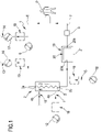
- FIG.1 shows a schematic representation of an extracorporeal blood treatment apparatus 1.
- the apparatus 1 comprises one blood treatment device 2, for example a hemofilter, a hemodiafilter, a plasmafilter, a dialysis filter or other unit suitable for processing the blood taken from a patient P.
- one blood treatment device 2 for example a hemofilter, a hemodiafilter, a plasmafilter, a dialysis filter or other unit suitable for processing the blood taken from a patient P.
- the blood treatment device 2 has a first compartment or blood chamber 3 and a second compartment or fluid chamber 4 separated from one another by a semipermeable membrane 5.
- a blood withdrawal line 6 is connected to an inlet port 3a of the blood chamber 3 and is configured, in an operative condition of connection to the patient P, to remove blood from a vascular access device inserted, for example in a fistula on the patient P.
- a blood return line 7 connected to an outlet port 3b of the blood chamber 3 is configured to receive treated blood from the treatment unit 2 and to return the treated blood, e.g. to a further vascular access also connected to the fistula of the patient P.
- vascular access device various configurations for the vascular access device may be envisaged: for example, typical access devices include a needle or catheter inserted into a vascular access which may be a fistula, a graft or a central (e.g. jugular vein) or peripheral vein (femoral vein) and so on.
- a vascular access which may be a fistula, a graft or a central (e.g. jugular vein) or peripheral vein (femoral vein) and so on.
- the blood withdrawal line 6 and the blood return line 7 are part of an extracorporeal blood circuit of the apparatus 1.
- the extracorporeal blood circuit 6, 7 and the treatment unit 2 are usually disposable parts which are loaded onto a frame of a blood treatment machine, not shown.
- the apparatus 1 comprises at least a first actuator, in the present example a blood pump 8, which is part of said machine and operates at the blood withdrawal line 6, to cause movement of the blood removed from the patient P from a first end of the withdrawal line 6 connected to the patient P to the blood chamber 3.
- the blood pump 8 is, for example, a peristaltic pump, as shown in FIG. 1 , which acts on a respective pump section of the withdrawal line 6.
- upstream and downstream may be used with reference to the relative positions taken by components belonging to or operating on the extracorporeal blood circuit. These terms are to be understood with reference to a blood flow direction from the first end of the blood withdrawal line 6 connected to the patient P towards the blood chamber 3 and then from the blood chamber 3 towards a second end of the blood return line 7 connected to the vascular access of the patient P.
- the apparatus 1 may further comprise an air trapping device 9 operating on the blood return line 7 (the air trapping device 9 is a venous deaeration chamber).
- the air trapping device 9 is placed online in the blood return line 7.
- a first section of the blood return line 7 puts in fluid communication the outlet port 3b of the blood chamber 3 with the air trapping device 9 and a second section of the blood return line 7 puts in fluid communication the air trapping device 9 with the patient P.
- the blood coming from the blood chamber 3 of the treatment device 2 enters and exits the air trapping device 9 before reaching the patient P.
- the apparatus 1 of FIG. 1 further comprises one fluid evacuation line 10 connected with an outlet port 4b of the fluid chamber 4 such as to receive the filtered waste fluid through the semipermeable membrane 5.
- the fluid evacuation line 10 receives such filtered waste fluid coming from the fluid chamber 4 of the treatment device 2, for example, comprising used dialysis liquid and/or liquid ultra-filtered through the membrane 5.
- the fluid evacuation line 10 leads to a receiving element, not shown, for example having a collection bag or a drainage pipe for the waste fluid.
- One or more dialysate pumps, not shown, may operate on the fluid evacuation line 10.
- a dialysis line 11 is also present for supplying a fresh treatment fluid into the inlet port 4a of the fluid chamber 4.
- the presence of this dialysis line 11 is not strictly necessary since, in the absence of the dialysis line 11, the apparatus 1 is still able to perform treatments such as ultrafiltration, hemofiltration or plasma-filtration.
- a fluid flow intercept device may be used, not shown, to selectively allow or inhibit fluid passage through the dialysis line 11, depending on whether or not a purification by diffusive effect is to be performed inside the treatment device 2.
- the dialysis line 11, if present, is typically equipped with a dialysis pump 12 and is able to receive a fresh fluid from a module, not shown, for example a bag or on-line preparation section of dialysis fluid, and to send such a fluid to the inlet port 4a of the fluid chamber 4.
- a module not shown, for example a bag or on-line preparation section of dialysis fluid
- the fluid evacuation line 10, the dialysis line 11 and the fluid chamber 4 are part of a treatment fluid circuit.
- the apparatus 1 as shown in FIG. 1 further comprises an infusion circuit comprising one or more infusion lines of a replacement fluid.
- a pre-infusion line 13 is connected to the blood withdrawal line 6 between the blood pump 8 and the inlet port 3a of the blood chamber 3.
- a pre pump infusion line 14 is connected to the blood withdrawal line 6 upstream of the blood pump 8, between said blood pump 8 and the vascular access device inserted in the fistula on the patient P.
- a post-infusion line 15 is connected to the blood return line 7 upstream of the air trapping device 9.
- Each of the pre- and/or post-infusion lines 13, 14, 15 are provided with a respective pump 16, 17, 18.
- the pre- and/or post-infusion lines 13, 14, 15 may be supplied by fluid coming from bags or directly by infusion fluid prepared on-line.
- Each of the pre- and/or post-infusion lines 13, 14, 15 are part of the treatment fluid circuit.
- the blood return line 7 presents a heated portion 19 in which blood is warmed before flowing into the blood circulation system of the patient P.
- the heated portion 19 comprises a disposable soft plastic bag 20 presenting a bag inlet 20a for blood to be warmed and coming from the blood chamber 3 of the blood treatment device 2 and a bag outlet 20b for warmed blood flowing towards the air trapping device 9 and then into the patient P.
- the bag 20 is placed in a seat of a warming unit 21 which is schematically represented in FIG. 1 .
- the extracorporeal blood treatment apparatus 1 may comprise heated portions 19 in the treatment fluid circuit to warm treatment fluid.
- heated portions 19 shown in dashed line in FIG. 1
- heated portions 19 may be present in the dialysis line 11, in the pre-infusion line 13, in the pre pump infusion line 14, in the post-infusion line 15.
- heated portions 19 too may comprise a bag placed in a seat of a warming unit.
- FIG.2 shows a schematic representation of an infusion apparatus 100 for intravenous infusions of medical fluids (like saline, saline and drug, nutritional solution or blood for transfusion).
- the apparatus of FIG. 2 is a IV pole infusion device provided with a vertical pole 101, a base 102 with a plurality of caster wheels and two top hooks 103.
- the vertical pole 101 carries an infusion device 104 provided with an infusion pump 105, for example a peristaltic pump and a control unit, not shown.
- an infusion pump 105 for example a peristaltic pump and a control unit, not shown.
- a container 106 like a flexible bag, for infusion fluid is suspended on one of the top hooks 103.
- a fluid line 107 departs from the infusion fluid container 106, goes through the infusion device 104 and presents a terminal end provided with a vascular access device inserted in the fistula on the patient P.
- the fluid line 107 is the fluid circuit configured to be coupled to the vascular access of the patient P.
- the peristaltic infusion pump 105 acts on a respective pump section of the fluid line 107.
- the infusion pump 105 causes a flow of infusion fluid along the fluid line 107 towards the patient P.
- the fluid line 107 Downstream of the infusion pump 105, the fluid line 107 presents the heated portion 19 in which infusion fluid is warmed before flowing into the blood circulation system of the patient P.
- the heated portion 19 comprises a plastic bag 20 presenting a bag inlet 20a for fluid to be warmed and coming from the infusion fluid container 106 and a bag outlet 20b for warmed fluid flowing towards the patient P.
- the bag 20 is placed in a seat of a casing of a warming unit 21 which is schematically represented in FIG. 2 .
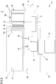
- FIG. 3 shows schematically a first embodiment of the warming unit 21 (which may be implemented in the extracorporeal blood treatment apparatus 1 of FIG. 1 or in the infusion apparatus 100 of FIG. 2 ) coupled to the bag 20 of the heated portion 19.
- Said heated portion 19 may be part of the blood return line 7 of the extracorporeal blood treatment apparatus 1 of FIG. 1 or may be part of the fluid line 107 of the infusion apparatus 100 of FIG. 2 .
- the warming unit 21 comprises a heat transfer element 22 shaped substantially like a metallic plate, optionally aluminum plate, having a first face 22a facing a face of the bag 20 which is substantially flat.
- the warming unit 21 comprises two heat transfer elements 22 shaped like two metallic plates parallel to each other and spaced one from the other to delimit the seat for the bag 20.
- the warming unit 21 comprises a casing which accommodates the two metallic plates delimiting the seat.
- the casing has a slot configured to insert the bag 20 between the two metallic plates.
- the heat transfer element or elements 22 is/are in contact or configured to be put in contact with the bag 20.
- the warming unit 21 further comprises an electrical heater element 23 provided with one or more electric resistors and connected to a main electrical source 24 (200V or 110V, 50/60 Hz) .
- the main electrical source 24 applies to the electrical heater element 23 a mains voltage "V" to generate heat.
- the electrical heater element 23 spreads over an area which is substantially equal to an area of the heat transfer element 22.
- the main electrical source 24 is connected to the electrical heater element 23.
- the electrical heater element 23 comprises two electric resistors, each operatively coupled to a respective heat transfer element / metallic plate 22.
- An electrical safety insulation 25 is interposed between the electrical heater element 23 and the heat transfer element 22.
- the electrical safety insulation 25 shown in figure 3 comprises a first and a second insulation layers 26, 27. Furthermore, the electrical heater element 23 is embedded in an insulation body 28.
- a mains circuit 29 of the warming unit 21 comprises the electrical heater element 23 and the main electrical source 24.
- a secondary circuit 30 of the warming unit 21 is isolated with respect to the mains circuit 29 and comprises the heat transfer element 22, the bag 20 and a warmer control circuitry 31 provided with a TRIAC control.
- the warming unit 21 further comprises a leakage current reduction circuit 32 operatively interposed between the heat transfer element 22 and a protective ground connection 33.
- the leakage current reduction circuit 32 comprises a resistance element 34 placed between the heat transfer element 22 and the protective ground connection 33, an electrical operated switch 36 placed in series with the resistance element 34 and configured to connect or disconnect the ground connection 22 to/from the heat transfer element 22 and a current sense circuitry 35 configured to sense the current through the resistance element 34 and to command the electrical operated switch 36.
- the electrical operated switch 36 is a solid state relay and the resistance element 34 has a resistance of 1 kOhm.
- the current sense circuitry 35 comprises a differential amplifier comprising two gain stages and a window comparator configured to detect the current through the resistance element 34.
- a first isolated power supply 37 and a second isolated power supply 38 are operatively interposed between the mains circuit 29 and the secondary circuit 30 to power the warmer control circuitry 31 and the leakage current reduction circuit 32.
- the leakage current reduction circuit 32 is configured to keep leakage currents below a first limit value (usually of 10 ⁇ A) under normal working conditions of the warming unit 21, in which the electrical heater element 23 is connected to the main electrical source 24 to perform heating, and to keep leakage currents below a second limit value (usually of 50 ⁇ A) under a fault condition of the warming unit 21 in which a patient P is connected to the mains voltage "V".
- the leakage currents are kept below the first limit value thanks to the resistance element 34 placed between the heat transfer element 22 and the protective ground connection 33.
- This connection steers parasitic heating currents through the heat transfer element and out the protective ground connection, which would normally flow through the patient, if the heat transfer element was not connected. These parasitic currents flow via capacitance between the electrical heater element to the heat transfer element, and capacitance between the heat transfer element to the patient fluid in the warming unit. Meanwhile, a current in the resistance element 34 is monitored through the current sense circuitry 35.
- a current flowing through the resistance element 34 is lower than a threshold current "i t " (e.g. of +/- 137 ⁇ A), the warming unit 21 keeps performing normal working conditions.
- the protective ground connection 33 is disconnected from the heat transfer element 22 but the electrical heater element 23 remains connected to the main electrical source 24 to keep heating.
- the electrical heater elements 23 are switched into the parallel state, which allows the same amount of heating power to be delivered with 1/4 of the TRIAC conduction time.
- the patient leakage current due to heating, while the heat transfer elements 22 are disconnected from protective ground connection 33, is proportional to the amount of time that the TRIACS are conducting.
- the electrical operated switch 36 is slowly turned back on every time interval " ⁇ t" (e.g. of 10 s), to determine if the patient P is still connected to mains "V".
- the electrical operated switch is immediately turned off. If a current below threshold current "i t " is detected, indicating the removal of the patient P connected to mains "V" fault condition, then the electrical operated switch 36 is fully turned on, connecting the heat transfer element 22 to protective ground connection 33 through the resistance element 34 again.
Landscapes
- Health & Medical Sciences (AREA)
- Heart & Thoracic Surgery (AREA)
- Vascular Medicine (AREA)
- Life Sciences & Earth Sciences (AREA)
- Engineering & Computer Science (AREA)
- Anesthesiology (AREA)
- Biomedical Technology (AREA)
- Hematology (AREA)
- Animal Behavior & Ethology (AREA)
- General Health & Medical Sciences (AREA)
- Public Health (AREA)
- Veterinary Medicine (AREA)
- Urology & Nephrology (AREA)
- Cardiology (AREA)
- Emergency Medicine (AREA)
- External Artificial Organs (AREA)
Priority Applications (5)
| Application Number | Priority Date | Filing Date | Title |
|---|---|---|---|
| PL18181135.7T PL3590559T3 (pl) | 2018-07-02 | 2018-07-02 | Urządzenie medyczne do wprowadzania płynu do układu krążenia krwi pacjenta i sposób sterowania prądami upływu w urządzeniu medycznym wyposażonym w jednostkę grzewczą lub z nią połączonym |
| EP18181135.7A EP3590559B1 (en) | 2018-07-02 | 2018-07-02 | Medical device for introduction of a fluid into the blood circulation system of a patient and method for controlling leakage currents in a medical device provided or combined with a warming unit |
| PCT/EP2019/066878 WO2020007666A1 (en) | 2018-07-02 | 2019-06-25 | Medical device for introduction of a fluid into the blood circulation system of a patient and method for controlling leakage currents in a medical device provided or combined with a warming unit |
| US17/256,417 US11957890B2 (en) | 2018-07-02 | 2019-06-25 | Medical device for introduction of a fluid into the blood circulation system of a patient and method for controlling leakage currents in a medical device provided or combined with a warming unit |
| CN201980044973.6A CN112384264B (zh) | 2018-07-02 | 2019-06-25 | 用于将流体引入患者的血液循环系统中的医疗装置及在设有或组合有加温单元的医疗装置中控制泄漏电流的方法 |
Applications Claiming Priority (1)
| Application Number | Priority Date | Filing Date | Title |
|---|---|---|---|
| EP18181135.7A EP3590559B1 (en) | 2018-07-02 | 2018-07-02 | Medical device for introduction of a fluid into the blood circulation system of a patient and method for controlling leakage currents in a medical device provided or combined with a warming unit |
Publications (2)
| Publication Number | Publication Date |
|---|---|
| EP3590559A1 EP3590559A1 (en) | 2020-01-08 |
| EP3590559B1 true EP3590559B1 (en) | 2022-11-16 |
Family
ID=62841957
Family Applications (1)
| Application Number | Title | Priority Date | Filing Date |
|---|---|---|---|
| EP18181135.7A Active EP3590559B1 (en) | 2018-07-02 | 2018-07-02 | Medical device for introduction of a fluid into the blood circulation system of a patient and method for controlling leakage currents in a medical device provided or combined with a warming unit |
Country Status (5)
| Country | Link |
|---|---|
| US (1) | US11957890B2 (pl) |
| EP (1) | EP3590559B1 (pl) |
| CN (1) | CN112384264B (pl) |
| PL (1) | PL3590559T3 (pl) |
| WO (1) | WO2020007666A1 (pl) |
Families Citing this family (3)
| Publication number | Priority date | Publication date | Assignee | Title |
|---|---|---|---|---|
| EP3701979A1 (de) * | 2019-02-26 | 2020-09-02 | Berlin Heart GmbH | Implantierbare blutpumpe zum unterstützen einer herzfunktion |
| US20230277744A1 (en) | 2020-07-17 | 2023-09-07 | Nxstage Medical, Inc. | Leakage Current Management Systems, Devices, and Methods |
| CN119055868A (zh) * | 2023-06-02 | 2024-12-03 | 甘布罗伦迪亚股份公司 | 体外血液治疗管道组件和装置 |
Family Cites Families (17)
| Publication number | Priority date | Publication date | Assignee | Title |
|---|---|---|---|---|
| US4155852A (en) * | 1976-11-19 | 1979-05-22 | Halbert Fischel | Low leakage current medical instrument |
| JPH1085323A (ja) | 1996-09-12 | 1998-04-07 | Meteku:Kk | 透析液加温ヒーター |
| JP4332829B2 (ja) * | 2000-06-14 | 2009-09-16 | 東レ・メディカル株式会社 | 透析システム |
| AU2003285871A1 (en) * | 2002-10-11 | 2005-08-16 | Medical Solutions, Inc. | Method and apparatus for controlling temperature of infused liquids |
| US7291123B2 (en) | 2003-06-04 | 2007-11-06 | Gambro Lundia | Joint for fluid transport lines for medical use |
| US20080058712A1 (en) * | 2006-08-31 | 2008-03-06 | Plahey Kulwinder S | Peritoneal dialysis machine with dual voltage heater circuit and method of operation |
| US9358331B2 (en) * | 2007-09-13 | 2016-06-07 | Fresenius Medical Care Holdings, Inc. | Portable dialysis machine with improved reservoir heating system |
| US10201647B2 (en) * | 2008-01-23 | 2019-02-12 | Deka Products Limited Partnership | Medical treatment system and methods using a plurality of fluid lines |
| US20140072288A1 (en) * | 2011-05-12 | 2014-03-13 | Nxstage Medical, Inc. | Fluid heating apparatuses, systems, and methods |
| US9999717B2 (en) * | 2011-05-24 | 2018-06-19 | Deka Products Limited Partnership | Systems and methods for detecting vascular access disconnection |
| EP3498316B1 (en) * | 2011-11-04 | 2020-07-22 | DEKA Products Limited Partnership | Medical treatment system and methods using a plurality of fluid lines |
| EP2700427B1 (de) | 2012-08-20 | 2014-11-26 | WWT Technischer Gerätebau GmbH | Fluidwärmer und Verfahren zum Betrieb eines Fluidwärmers |
| DK2764881T3 (da) * | 2013-02-06 | 2019-10-28 | Medirio Sa | System til medicinsk behandling |
| EP2765825B1 (de) * | 2013-02-07 | 2015-04-22 | Stihler Electronic GmbH | Fluidwärmer und Verfahren zum Betrieb eines Fluidwärmers |
| EP2848269B1 (en) * | 2013-09-12 | 2016-05-25 | Gambro Lundia | Apparatus for extracorporeal treatment of blood and method of control of a blood-warming device in an extracorporeal blood treatment apparatus |
| EP3103495B1 (en) * | 2015-06-10 | 2018-08-29 | B. Braun Avitum AG | Solution circuit apparatus with bypass, and blood purification system comprising the solution circuit apparatus |
| US10569007B2 (en) | 2015-10-14 | 2020-02-25 | Gambro Lundia Ab | Dialysis system and method including a flow path insulator |
-
2018
- 2018-07-02 PL PL18181135.7T patent/PL3590559T3/pl unknown
- 2018-07-02 EP EP18181135.7A patent/EP3590559B1/en active Active
-
2019
- 2019-06-25 WO PCT/EP2019/066878 patent/WO2020007666A1/en not_active Ceased
- 2019-06-25 US US17/256,417 patent/US11957890B2/en active Active
- 2019-06-25 CN CN201980044973.6A patent/CN112384264B/zh active Active
Also Published As
| Publication number | Publication date |
|---|---|
| WO2020007666A1 (en) | 2020-01-09 |
| US20210268205A1 (en) | 2021-09-02 |
| CN112384264B (zh) | 2024-06-04 |
| CN112384264A (zh) | 2021-02-19 |
| EP3590559A1 (en) | 2020-01-08 |
| US11957890B2 (en) | 2024-04-16 |
| PL3590559T3 (pl) | 2023-04-17 |
Similar Documents
| Publication | Publication Date | Title |
|---|---|---|
| US8777887B2 (en) | Medical apparatus | |
| EP2255840B1 (en) | System for detecting patient access disconnection | |
| US11957890B2 (en) | Medical device for introduction of a fluid into the blood circulation system of a patient and method for controlling leakage currents in a medical device provided or combined with a warming unit | |
| EP1894586A2 (en) | Peritoneal dialysis machine with dual voltage heater circuit and method of operation | |
| EP1061971B1 (en) | Apparatus for dialysis with blood-warmer | |
| US11696386B2 (en) | Renal failure therapy system having an electrically floating fluid pathway | |
| US9435478B2 (en) | Fluid warmer and method of operating a fluid warmer | |
| EP3362118A1 (en) | Renal failure therapy system and method for electrically safe treatment | |
| EP3431119B1 (en) | Apparatus for extracorporeal treatment of blood | |
| CA2582856C (en) | Continuous renal replacement therapy heat loss compensation |
Legal Events
| Date | Code | Title | Description |
|---|---|---|---|
| PUAI | Public reference made under article 153(3) epc to a published international application that has entered the european phase |
Free format text: ORIGINAL CODE: 0009012 |
|
| STAA | Information on the status of an ep patent application or granted ep patent |
Free format text: STATUS: THE APPLICATION HAS BEEN PUBLISHED |
|
| AK | Designated contracting states |
Kind code of ref document: A1 Designated state(s): AL AT BE BG CH CY CZ DE DK EE ES FI FR GB GR HR HU IE IS IT LI LT LU LV MC MK MT NL NO PL PT RO RS SE SI SK SM TR |
|
| AX | Request for extension of the european patent |
Extension state: BA ME |
|
| STAA | Information on the status of an ep patent application or granted ep patent |
Free format text: STATUS: REQUEST FOR EXAMINATION WAS MADE |
|
| 17P | Request for examination filed |
Effective date: 20200410 |
|
| RBV | Designated contracting states (corrected) |
Designated state(s): AL AT BE BG CH CY CZ DE DK EE ES FI FR GB GR HR HU IE IS IT LI LT LU LV MC MK MT NL NO PL PT RO RS SE SI SK SM TR |
|
| GRAJ | Information related to disapproval of communication of intention to grant by the applicant or resumption of examination proceedings by the epo deleted |
Free format text: ORIGINAL CODE: EPIDOSDIGR1 |
|
| RIC1 | Information provided on ipc code assigned before grant |
Ipc: H05B 1/02 20060101ALI20220715BHEP Ipc: A61M 5/44 20060101ALI20220715BHEP Ipc: A61M 5/14 20060101ALI20220715BHEP Ipc: A61M 1/16 20060101AFI20220715BHEP |
|
| GRAP | Despatch of communication of intention to grant a patent |
Free format text: ORIGINAL CODE: EPIDOSNIGR1 |
|
| STAA | Information on the status of an ep patent application or granted ep patent |
Free format text: STATUS: GRANT OF PATENT IS INTENDED |
|
| INTG | Intention to grant announced |
Effective date: 20220812 |
|
| INTG | Intention to grant announced |
Effective date: 20220818 |
|
| INTC | Intention to grant announced (deleted) | ||
| INTG | Intention to grant announced |
Effective date: 20220831 |
|
| GRAS | Grant fee paid |
Free format text: ORIGINAL CODE: EPIDOSNIGR3 |
|
| GRAA | (expected) grant |
Free format text: ORIGINAL CODE: 0009210 |
|
| STAA | Information on the status of an ep patent application or granted ep patent |
Free format text: STATUS: THE PATENT HAS BEEN GRANTED |
|
| AK | Designated contracting states |
Kind code of ref document: B1 Designated state(s): AL AT BE BG CH CY CZ DE DK EE ES FI FR GB GR HR HU IE IS IT LI LT LU LV MC MK MT NL NO PL PT RO RS SE SI SK SM TR |
|
| REG | Reference to a national code |
Ref country code: GB Ref legal event code: FG4D |
|
| REG | Reference to a national code |
Ref country code: CH Ref legal event code: EP |
|
| REG | Reference to a national code |
Ref country code: IE Ref legal event code: FG4D |
|
| REG | Reference to a national code |
Ref country code: DE Ref legal event code: R096 Ref document number: 602018043057 Country of ref document: DE |
|
| REG | Reference to a national code |
Ref country code: AT Ref legal event code: REF Ref document number: 1531377 Country of ref document: AT Kind code of ref document: T Effective date: 20221215 |
|
| REG | Reference to a national code |
Ref country code: LT Ref legal event code: MG9D |
|
| REG | Reference to a national code |
Ref country code: NL Ref legal event code: MP Effective date: 20221116 |
|
| REG | Reference to a national code |
Ref country code: AT Ref legal event code: MK05 Ref document number: 1531377 Country of ref document: AT Kind code of ref document: T Effective date: 20221116 |
|
| PG25 | Lapsed in a contracting state [announced via postgrant information from national office to epo] |
Ref country code: SE Free format text: LAPSE BECAUSE OF FAILURE TO SUBMIT A TRANSLATION OF THE DESCRIPTION OR TO PAY THE FEE WITHIN THE PRESCRIBED TIME-LIMIT Effective date: 20221116 Ref country code: PT Free format text: LAPSE BECAUSE OF FAILURE TO SUBMIT A TRANSLATION OF THE DESCRIPTION OR TO PAY THE FEE WITHIN THE PRESCRIBED TIME-LIMIT Effective date: 20230316 Ref country code: NO Free format text: LAPSE BECAUSE OF FAILURE TO SUBMIT A TRANSLATION OF THE DESCRIPTION OR TO PAY THE FEE WITHIN THE PRESCRIBED TIME-LIMIT Effective date: 20230216 Ref country code: LT Free format text: LAPSE BECAUSE OF FAILURE TO SUBMIT A TRANSLATION OF THE DESCRIPTION OR TO PAY THE FEE WITHIN THE PRESCRIBED TIME-LIMIT Effective date: 20221116 Ref country code: FI Free format text: LAPSE BECAUSE OF FAILURE TO SUBMIT A TRANSLATION OF THE DESCRIPTION OR TO PAY THE FEE WITHIN THE PRESCRIBED TIME-LIMIT Effective date: 20221116 Ref country code: ES Free format text: LAPSE BECAUSE OF FAILURE TO SUBMIT A TRANSLATION OF THE DESCRIPTION OR TO PAY THE FEE WITHIN THE PRESCRIBED TIME-LIMIT Effective date: 20221116 Ref country code: AT Free format text: LAPSE BECAUSE OF FAILURE TO SUBMIT A TRANSLATION OF THE DESCRIPTION OR TO PAY THE FEE WITHIN THE PRESCRIBED TIME-LIMIT Effective date: 20221116 |
|
| PG25 | Lapsed in a contracting state [announced via postgrant information from national office to epo] |
Ref country code: RS Free format text: LAPSE BECAUSE OF FAILURE TO SUBMIT A TRANSLATION OF THE DESCRIPTION OR TO PAY THE FEE WITHIN THE PRESCRIBED TIME-LIMIT Effective date: 20221116 Ref country code: LV Free format text: LAPSE BECAUSE OF FAILURE TO SUBMIT A TRANSLATION OF THE DESCRIPTION OR TO PAY THE FEE WITHIN THE PRESCRIBED TIME-LIMIT Effective date: 20221116 Ref country code: IS Free format text: LAPSE BECAUSE OF FAILURE TO SUBMIT A TRANSLATION OF THE DESCRIPTION OR TO PAY THE FEE WITHIN THE PRESCRIBED TIME-LIMIT Effective date: 20230316 Ref country code: HR Free format text: LAPSE BECAUSE OF FAILURE TO SUBMIT A TRANSLATION OF THE DESCRIPTION OR TO PAY THE FEE WITHIN THE PRESCRIBED TIME-LIMIT Effective date: 20221116 Ref country code: GR Free format text: LAPSE BECAUSE OF FAILURE TO SUBMIT A TRANSLATION OF THE DESCRIPTION OR TO PAY THE FEE WITHIN THE PRESCRIBED TIME-LIMIT Effective date: 20230217 |
|
| PG25 | Lapsed in a contracting state [announced via postgrant information from national office to epo] |
Ref country code: NL Free format text: LAPSE BECAUSE OF FAILURE TO SUBMIT A TRANSLATION OF THE DESCRIPTION OR TO PAY THE FEE WITHIN THE PRESCRIBED TIME-LIMIT Effective date: 20221116 |
|
| PG25 | Lapsed in a contracting state [announced via postgrant information from national office to epo] |
Ref country code: SM Free format text: LAPSE BECAUSE OF FAILURE TO SUBMIT A TRANSLATION OF THE DESCRIPTION OR TO PAY THE FEE WITHIN THE PRESCRIBED TIME-LIMIT Effective date: 20221116 Ref country code: RO Free format text: LAPSE BECAUSE OF FAILURE TO SUBMIT A TRANSLATION OF THE DESCRIPTION OR TO PAY THE FEE WITHIN THE PRESCRIBED TIME-LIMIT Effective date: 20221116 Ref country code: EE Free format text: LAPSE BECAUSE OF FAILURE TO SUBMIT A TRANSLATION OF THE DESCRIPTION OR TO PAY THE FEE WITHIN THE PRESCRIBED TIME-LIMIT Effective date: 20221116 Ref country code: DK Free format text: LAPSE BECAUSE OF FAILURE TO SUBMIT A TRANSLATION OF THE DESCRIPTION OR TO PAY THE FEE WITHIN THE PRESCRIBED TIME-LIMIT Effective date: 20221116 Ref country code: CZ Free format text: LAPSE BECAUSE OF FAILURE TO SUBMIT A TRANSLATION OF THE DESCRIPTION OR TO PAY THE FEE WITHIN THE PRESCRIBED TIME-LIMIT Effective date: 20221116 |
|
| REG | Reference to a national code |
Ref country code: DE Ref legal event code: R097 Ref document number: 602018043057 Country of ref document: DE |
|
| PG25 | Lapsed in a contracting state [announced via postgrant information from national office to epo] |
Ref country code: SK Free format text: LAPSE BECAUSE OF FAILURE TO SUBMIT A TRANSLATION OF THE DESCRIPTION OR TO PAY THE FEE WITHIN THE PRESCRIBED TIME-LIMIT Effective date: 20221116 Ref country code: AL Free format text: LAPSE BECAUSE OF FAILURE TO SUBMIT A TRANSLATION OF THE DESCRIPTION OR TO PAY THE FEE WITHIN THE PRESCRIBED TIME-LIMIT Effective date: 20221116 |
|
| PLBE | No opposition filed within time limit |
Free format text: ORIGINAL CODE: 0009261 |
|
| STAA | Information on the status of an ep patent application or granted ep patent |
Free format text: STATUS: NO OPPOSITION FILED WITHIN TIME LIMIT |
|
| 26N | No opposition filed |
Effective date: 20230817 |
|
| PG25 | Lapsed in a contracting state [announced via postgrant information from national office to epo] |
Ref country code: SI Free format text: LAPSE BECAUSE OF FAILURE TO SUBMIT A TRANSLATION OF THE DESCRIPTION OR TO PAY THE FEE WITHIN THE PRESCRIBED TIME-LIMIT Effective date: 20221116 |
|
| PG25 | Lapsed in a contracting state [announced via postgrant information from national office to epo] |
Ref country code: MC Free format text: LAPSE BECAUSE OF FAILURE TO SUBMIT A TRANSLATION OF THE DESCRIPTION OR TO PAY THE FEE WITHIN THE PRESCRIBED TIME-LIMIT Effective date: 20221116 |
|
| PG25 | Lapsed in a contracting state [announced via postgrant information from national office to epo] |
Ref country code: MC Free format text: LAPSE BECAUSE OF FAILURE TO SUBMIT A TRANSLATION OF THE DESCRIPTION OR TO PAY THE FEE WITHIN THE PRESCRIBED TIME-LIMIT Effective date: 20221116 |
|
| REG | Reference to a national code |
Ref country code: CH Ref legal event code: PL |
|
| REG | Reference to a national code |
Ref country code: BE Ref legal event code: MM Effective date: 20230731 |
|
| PG25 | Lapsed in a contracting state [announced via postgrant information from national office to epo] |
Ref country code: LU Free format text: LAPSE BECAUSE OF NON-PAYMENT OF DUE FEES Effective date: 20230702 |
|
| PG25 | Lapsed in a contracting state [announced via postgrant information from national office to epo] |
Ref country code: LU Free format text: LAPSE BECAUSE OF NON-PAYMENT OF DUE FEES Effective date: 20230702 |
|
| REG | Reference to a national code |
Ref country code: IE Ref legal event code: MM4A |
|
| PG25 | Lapsed in a contracting state [announced via postgrant information from national office to epo] |
Ref country code: CH Free format text: LAPSE BECAUSE OF NON-PAYMENT OF DUE FEES Effective date: 20230731 |
|
| PG25 | Lapsed in a contracting state [announced via postgrant information from national office to epo] |
Ref country code: BE Free format text: LAPSE BECAUSE OF NON-PAYMENT OF DUE FEES Effective date: 20230731 |
|
| PG25 | Lapsed in a contracting state [announced via postgrant information from national office to epo] |
Ref country code: IE Free format text: LAPSE BECAUSE OF NON-PAYMENT OF DUE FEES Effective date: 20230702 |
|
| PG25 | Lapsed in a contracting state [announced via postgrant information from national office to epo] |
Ref country code: IE Free format text: LAPSE BECAUSE OF NON-PAYMENT OF DUE FEES Effective date: 20230702 |
|
| PG25 | Lapsed in a contracting state [announced via postgrant information from national office to epo] |
Ref country code: BG Free format text: LAPSE BECAUSE OF FAILURE TO SUBMIT A TRANSLATION OF THE DESCRIPTION OR TO PAY THE FEE WITHIN THE PRESCRIBED TIME-LIMIT Effective date: 20221116 |
|
| PG25 | Lapsed in a contracting state [announced via postgrant information from national office to epo] |
Ref country code: BG Free format text: LAPSE BECAUSE OF FAILURE TO SUBMIT A TRANSLATION OF THE DESCRIPTION OR TO PAY THE FEE WITHIN THE PRESCRIBED TIME-LIMIT Effective date: 20221116 |
|
| PGFP | Annual fee paid to national office [announced via postgrant information from national office to epo] |
Ref country code: PL Payment date: 20250623 Year of fee payment: 8 |
|
| PGFP | Annual fee paid to national office [announced via postgrant information from national office to epo] |
Ref country code: GB Payment date: 20250619 Year of fee payment: 8 |
|
| PGFP | Annual fee paid to national office [announced via postgrant information from national office to epo] |
Ref country code: FR Payment date: 20250620 Year of fee payment: 8 |
|
| PG25 | Lapsed in a contracting state [announced via postgrant information from national office to epo] |
Ref country code: CY Free format text: LAPSE BECAUSE OF FAILURE TO SUBMIT A TRANSLATION OF THE DESCRIPTION OR TO PAY THE FEE WITHIN THE PRESCRIBED TIME-LIMIT; INVALID AB INITIO Effective date: 20180702 |
|
| PG25 | Lapsed in a contracting state [announced via postgrant information from national office to epo] |
Ref country code: HU Free format text: LAPSE BECAUSE OF FAILURE TO SUBMIT A TRANSLATION OF THE DESCRIPTION OR TO PAY THE FEE WITHIN THE PRESCRIBED TIME-LIMIT; INVALID AB INITIO Effective date: 20180702 |
|
| PGFP | Annual fee paid to national office [announced via postgrant information from national office to epo] |
Ref country code: DE Payment date: 20250620 Year of fee payment: 8 |
|
| PGFP | Annual fee paid to national office [announced via postgrant information from national office to epo] |
Ref country code: IT Payment date: 20250619 Year of fee payment: 8 |
|
| PG25 | Lapsed in a contracting state [announced via postgrant information from national office to epo] |
Ref country code: TR Free format text: LAPSE BECAUSE OF FAILURE TO SUBMIT A TRANSLATION OF THE DESCRIPTION OR TO PAY THE FEE WITHIN THE PRESCRIBED TIME-LIMIT Effective date: 20221116 |