EP3590464B1 - Verarbeitungsverfahren, verarbeitungssystem und verarbeitungsprogramm - Google Patents
Verarbeitungsverfahren, verarbeitungssystem und verarbeitungsprogramm Download PDFInfo
- Publication number
- EP3590464B1 EP3590464B1 EP19183366.4A EP19183366A EP3590464B1 EP 3590464 B1 EP3590464 B1 EP 3590464B1 EP 19183366 A EP19183366 A EP 19183366A EP 3590464 B1 EP3590464 B1 EP 3590464B1
- Authority
- EP
- European Patent Office
- Prior art keywords
- laser beam
- processing
- dental material
- sites
- laser
- Prior art date
- Legal status (The legal status is an assumption and is not a legal conclusion. Google has not performed a legal analysis and makes no representation as to the accuracy of the status listed.)
- Active
Links
Images

Classifications
-
- A—HUMAN NECESSITIES
- A61—MEDICAL OR VETERINARY SCIENCE; HYGIENE
- A61C—DENTISTRY; APPARATUS OR METHODS FOR ORAL OR DENTAL HYGIENE
- A61C13/00—Dental prostheses; Making same
- A61C13/0003—Making bridge-work, inlays, implants or the like
- A61C13/0006—Production methods
- A61C13/0018—Production methods using laser
-
- A—HUMAN NECESSITIES
- A61—MEDICAL OR VETERINARY SCIENCE; HYGIENE
- A61C—DENTISTRY; APPARATUS OR METHODS FOR ORAL OR DENTAL HYGIENE
- A61C13/00—Dental prostheses; Making same
- A61C13/0003—Making bridge-work, inlays, implants or the like
- A61C13/0004—Computer-assisted sizing or machining of dental prostheses
-
- A—HUMAN NECESSITIES
- A61—MEDICAL OR VETERINARY SCIENCE; HYGIENE
- A61C—DENTISTRY; APPARATUS OR METHODS FOR ORAL OR DENTAL HYGIENE
- A61C19/00—Dental auxiliary appliances
- A61C19/003—Apparatus for curing resins by radiation
Definitions
- the present invention relates to processing methods, processing systems, and processing programs.
- dental prostheses used for dental care (hereinafter, referred to as “dentistry prostheses”), such as dentures and implants.
- dental prostheses are made by carving a dental material into the shape of a natural tooth.
- Natural teeth have different transmittances varying with each tooth.
- central and lateral incisors are usually opaque on the bottom side (gingival side) and their transmittance gradually increases toward the incisal side. Therefore, despite the dental materials being carved into the shape of a natural tooth, the resultant products disfigure wearers owing to the transmittance of the finished dentistry prostheses differing from that of the natural teeth.
- JP-A-2014-141388 discloses a technique involving colored zirconia-based sintered materials with high density, strength, and superior light transmittance.
- JP-A-2017-122064 discloses a technique involving ceramic materials using which the transmittance of dentistry products can be increased.
- WO2009/073498A1 discloses a processing method, a laser processing systems and a processing program according to the preambles of the independent claims 1, 10 and 11.
- An object of the present invention is to provide a technique using which dental materials with a transmittance closer to that of an individual's natural tooth can be easily obtained.
- dental materials with a transmittance closer to that of an individual's natural tooth can be easily obtained.
- a transmittance of a dental material is changed by projecting a laser beam into the dental material and changing character.
- the use of laser beams makes it possible to achieve processing without any contact.
- transmittance refers to the percentage of light (such as white light) of a certain wavelength that passes through a material.
- Dental materials are those from which dentistry prostheses are fabricated. Dental materials which transmit laser radiation (light-transmitting materials) are used as dental materials of this embodiment. Examples of light-transmitting materials that can be used include zirconia-based materials. Zirconia-based materials may be composite materials such as zirconia-containing glass ceramics or zirconia alone with a certain transmittance. Materials do not require 100% or equivalent light transmittance and any transmittance value will suffice as long as the laser beam reaches a certain position for processing.
- zirconia-based materials are preferably sintered materials (final sintered materials). Unlike partially sintered materials, fully sintered materials do not require calcination after processing, that contributes to the reduction of processing time. Moreover, fully sintered materials are immune to contraction associated with the calcination of partially sintered materials; therefore, processing precision does not deteriorate.
- Ultrashort-pulsed lasers emit laser pulses with durations from picoseconds to femtoseconds.
- Ablation non-thermal processing
- Ablation can be performed by exposing a certain site inside the material to laser pulses emitted from an ultrashort-pulsed laser for a short duration.
- the portion of material that is molten using the laser pulses instantaneously evaporates and scatters, thereby being eliminated; therefore, damage due to heat is less than that using typical laser machining (thermal processing). Therefore, ablation is particularly effective for processing small-sized objects, such as dentistry prostheses.
- Character change refers to the change of materials in terms of their composition and structure.
- the character By projecting a laser beam onto a certain site inside a dental material, the character is changed at that site, and a processing mark is formed. That is, each processing mark is a region where the character has been changed via a laser beam.
- a region where a processing mark is formed (a region with a changed character) has a lower light transmittance compared with other region (a region not exposed to a laser beam) owing to, for example, the influence of reflection and/or scattering. Therefore, the desired sites of dental materials with a desired transmittance may be rendered by adjusting the size, position, the number of processing marks or the density in case two or more processing marks are formed (details are described later).
- the processing method according to this embodiment is performed, based on a processing data, by a laser processing system 200.
- Fig. 1 is a diagram showing a CAD/CAM system 100 and the laser processing system 200.
- the CAD/CAM system 100 produces processing data and supplies them to the laser processing system 200.
- the format of the supplied data is not limited as long as the data can be used in the laser processing system 200.
- the processing data is used in the laser processing system 200 upon projecting a laser beam into a dental material. Specifically, the processing data is for obtaining dental materials with a transmittance closer to that of natural teeth of each individual.
- Each processing data includes information about the site at which a laser beam is projected inside a dental material, information about the transmittance, and laser projection conditions (e.g., spot size, intensity, projection time etc.).
- the site at which a laser beam is projected is set as one or more points, line segments (straight lines or curves), planes (two-dimensional regions with a certain surface area), or solids (three-dimensional regions with a certain volume).
- Information about transmittance is for determining the value by which the transmittance of the dental material is to be reduced.
- the data corresponding to each point has three-dimensional (XYZ) coordinate values and vector information.
- Each ordered triple is used to determine the focal position of the laser beam (i.e., each ordered triple corresponds to the position at which the laser beam is projected inside the material). Coordinate values are determined in consideration of information about transmittance. For example, when the transmittance is set to a low value, the CAD/CAM system 100 sets the coordinate values so that the density of processing marks formed by projecting the laser beam increases (the distance between points reduces). Alternatively, when the transmittance is set to have a low value, the CAD/CAM system 100 sets projection conditions (spot size and intensity) of the laser beam so that the size of each processing mark formed by projecting the laser beam becomes large.
- the vector information is used in determining the projection direction of each laser beam (the direction of the laser beam directed to the material).
- the direction of the laser beam directed to the material the direction of the laser beam directed to the material.
- the CAD/CAM system 100 may change one or more coordinates (the position(s) at which the laser beam is projected) in consideration of the material's refractive index.
- the processing data may include order data indicating from which site the laser beam is to be projected (the order of projecting a laser beam).
- the order data is set so that the laser beam is projected onto the overlapped sites in descending order of distance from a material surface through which the laser beam passes (in a series that begins with the farthest and ends with the closest to the material surface). The distance between the surface of the material and each site at which the laser is projected is determined in the direction in which the laser beam is directed.
- the laser processing system 200 includes a processing device 1 and a computer 2. It should be noted that the laser processing system 200 can be formed by the processing device 1 alone when the functions of the computer 2 are integrated into the processing device 1.
- the processing device 1 has three driving axes (the x-, y-, and z-axes) perpendicular to each other as well as two rotation axes (a rotation axis around the x-axis and a rotation axis around the y-axis).
- the processing device 1 projects a laser beam into a dental material based on a processing data.
- the processing device 1 includes a projection unit 10, a holding unit 20, and a drive mechanism 30.
- the projection unit 10 is for projecting laser beams towards dental materials.
- the projection unit 10 comprises an oscillator and an optical system.
- the oscillator oscillates a laser beam having a certain intensity.
- the oscillator can adjust the intensity of the laser beam in accordance with the projection condition included in the processing data.
- the optical system is, for example, a group of lenses for directing the laser beam produced by the oscillator to each material.
- an adjustment unit may be provided in the projection unit 10.
- the adjustment unit adjusts a spot size and a projection pattern of each laser beam.
- the adjustment unit is a member such as a galvanometer mirror, a Fresnel lens, a diffractive optical element (DOE), or a spatial light phase modulator (LCOS-SLM).
- the adjustment unit is disposed, for example, between the oscillator and the group of lenses in the projection unit 10.
- the projection pattern can be, for example, a pattern in which a laser beam of a certain spot diameter is projected onto a certain site inside the material as a point or a pattern in which a laser beam of a certain spot diameter is projected while scanning it in a certain direction.
- Such projection patterns can be achieved by using, for example, a galvanometer mirror as an adjustment unit.
- laser beams can be projected onto a two-dimensional area or a three-dimensional area collectively.
- Such projection patterns can be achieved, for example, by using a spatial light phase modulator as an adjustment unit.
- the adjustment unit in this embodiment can change a spot size for each site when a laser beam is projected with each projection pattern.
- the spot size corresponds to the diameter (spot diameter) of the laser beam
- the spot size corresponds to the surface area of the two-dimensional region or the volume of the three-dimensional region.
- the holding unit 20 is for holding a dental material Any method can be used for holding the dental material as long as the dental material being held can be moved and rotated along five axes.
- the drive mechanism 30 moves the projection unit 10 and the holding unit 20 relative to each other.
- the driving mechanism 30 includes a driving motor and other components.
- the drive mechanism 30 can move at least one of the projection unit 10 and the holding unit 20 in the three, i.e., x-, y-, and z-directions at the same time.
- the computer 2 controls operations of the projection unit 10 and the drive mechanism 30.
- the controller 2 controls the projection unit 10 and the drive mechanism 30 such that a transmittance of the dental material is changed by projecting a laser beam into the dental material and changing character.
- the computer 2 controls, based on the processing data, the drive mechanism 30 such that the laser beam can be projected onto a certain site inside the dental material (such that a certain site coincides with the focal position of the laser beam) to adjust the relative position of the projection unit 10 and the holding unit 20 (the dental material held by the holding unit 20). Furthermore, the computer 2 controls the projection unit 10 to adjust the spot size and the intensity of the laser beam to be projected. Then, the computer 2 controls the projection unit 10 to project the laser beam onto the dental material for a certain amount of time. A change of character occurs at the site that has been exposed to the laser beam and a processing mark is formed there.
- the computer 2 is an example of the "control unit.”
- the spot size, intensity, and projection time affect the power (energy) of the projected laser beam.
- These parameters may be included beforehand in the processing data as described above, or may be set by the processing device 1.
- the processing device 1 may perform some corrections based on the refractive index of the dental material.
- the laser processing system 200 does not necessary have five axes.
- a processing device with three axes i.e., a driving axis for driving the projection unit 10 in the z-direction and driving axes for driving the holding unit 20 in the x- and y-directions, can also be used.
- Figs. 2 to 6 a specific example of the processing method according to this embodiment is described.
- the processing method has been installed beforehand on the laser processing system 200 as a dedicated processing program.
- a laser beam is projected into a dental material M that has been formed to have a shape similar to that of a natural tooth.
- the shaping can be performed using a known machining device.
- Fig. 2 is a flow chart showing a sequence of operations of the laser processing system 200.
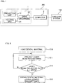
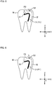
- Figs. 3 to 6 are diagrams schematically showing the inside of the dental material M that is subjected to processing using the processing method according to this embodiment.
- the x-, y-, and z-axes shown in Figs. 3 to 6 represent three axes perpendicular to each other.
- the processing data for the dental material M is produced beforehand by the CAD/CAM system 100.
- An operator loads a dental material M into the holding unit 20 of the processing device 1 (load a dental material; step 10).
- the computer 2 causes the processing device 1 to project a laser beam based on the processing data for the dental material M.
- the computer 2 allows a laser beam to be projected based onto a site represented by the processing data (a site inside the material whose transmittance is desired to be changed) and projection conditions (project a laser beam into the material; step 11).
- each site at which a laser beam is to be projected is a curved line represented by a dotted line and processing marks formed by projecting the laser beam are shown by solid lines.
- the computer 2 can project a laser beam L onto a plurality of sites (sites P1 and P2) along the contour of the surface of the dental material M.
- the width of a processing mark I1 formed by projecting the laser beam to the site P1 is almost equal to the width of a processing mark 12 formed by projecting the laser beam onto the site P2.
- Fig. 3 shows an example in which the site P1 has already been subjected to laser projection and the processing mark I1 has been formed.
- the computer 2 can project the laser beam L onto a plurality of sites (sites P1 to P4) that are apart from each other at different intervals.
- the distance between the sites P1 and P2 and the distance between the sites P2 and P3 are smaller (dense) than the distance between the sites P3 and P4. Accordingly, it can be said that processing marks I1 to 14 formed by projecting the laser beam onto the sites P1 to P4 have different densities from each other.
- Fig. 4 shows an example in which the sites P1 to P3 have already been subjected to laser projection and the processing marks I1 to 13 have been formed.
- the computer 2 can change, in the case that the laser beam L is projected onto a plurality of sites (the sites P1 and P2), the spot diameter of the laser beam L for each of the sites P1 and P2.
- a spot diameter S1 of a laser beam projected onto the site P1 is larger than a spot diameter S2 of a laser beam projected onto the site P2.
- the width of the processing mark I1 formed by projecting the laser beam onto the site P1 is larger than the width of the processing mark I2 formed by projecting the laser beam onto the site P2.
- Fig. 5 shows an example in which the site P1 has already been subjected to laser projection and the processing mark II has been formed.
- the computer 2 can change, in the case that the laser beam L is projected onto a plurality of sites (the sites P1 and P2), the intensity of the laser beam for each of the sites P1 and P2.
- the laser beam projected onto the site P1 has a larger intensity than the laser beam projected onto the site P2.
- the laser beams projected onto the sites P1 and P2 have similar spot diameters S1 and S2, respectively, whereas the width of the processing mark I1 formed by projecting the laser beam onto the site P1 is larger than the width of the processing mark 12 formed by projecting the laser beam onto the site P2 does.
- Fig. 6 shows an example in which the site P1 has already been subjected to laser projection and the processing mark I1 has been formed.
- the laser beam is projected onto sites such that paths of the laser beam are overlapping with each other
- a change of character of the material occurs at the site where the laser beam is projected first and it is possible that no laser beams can be projected anymore onto other sites located on the farther side (further inside the material).
- the laser beam is projected from the top downward in the z-direction in the example shown in Fig. 3
- the site P2 is exposed to the laser beam first, it is possible that no laser beams can be projected onto the site P1 located further inside the site P2 as a result of a change of character at the site P2.
- the laser beam is projected onto sites such that paths of the laser beam are overlapping with each other, the laser beam is projected onto the overlapped sites in descending order of distance from a material surface through which the laser beam passes.
- the computer 2 controls the projection unit 10 and causes it to project the laser beam onto the site P1 that lies farthest off from the material surface. Then, the computer 2 controls the projection unit 10 and projects the laser beam onto the site P2 that lies farthest off from the material surface but the site P1.
- the order of the laser projection can be determined using the order data included in the processing data. In the case that the laser beam is projected onto each of the sites P1 and P2, it is preferable that the laser is projected onto positions on the curve of the site P1 (site P2) in the descending order of distance from the material surface through which the laser beam passes.
- the computer 2 can control the projection unit 10 and causes it to project the laser beam onto the site that has been corrected. Furthermore, the computer 2 can adjust the relative position between the projection unit 10 and the holding unit 20 such that the laser beam is vertically directed to the surface of the dental material M.
- two or more methods of projecting the laser beam can be used in combination.
- both of the intensity and the spot size of the laser beam may be changed.
- the intensity and/or the spot size of the laser beam can be changed in the middle of the site P1 shown in Fig. 3 and other figures.
- a dental material M having a desired transmittance can be obtained (obtain a dental material having a desired transmittance; step 13). It should be noted that the dental material M is the one that has already been subjected to calcination and finishing, the dental material M obtained in step 13 can be used as a dentistry prosthesis without any further processing.
- the transmittance of the dental material M is changed by projecting a laser beam into the dental material M and changing character.
- the transmittance of the part where a processing mark has been formed becomes different from the transmittance of the remainder. Accordingly, by adjusting processing marks such that a transmittance closer to that of a natural tooth of a certain individual can be achieved, it is possible to provide a dentistry prosthesis suitable for each person. In this case, it is unnecessary to adjust the composition of the dental material for each person because what is required is only to process inside the dental material with a laser beam. Thus, with the processing method according to this embodiment, dental materials with a transmittance closer to that of an individual's natural tooth can be easily obtained.
- the processing method it is possible to project, in the case that the laser beam is projected onto two or more sites, the laser beam such that processing marks formed by projecting the laser beam have different densities from each other.
- the densities of the processing marks it is possible to adjust the transmittance of the dental material more precisely.
- a spot size of the laser beam can be changed for each of the sites.
- the spot size of the laser beam it is possible to adjust the size of the processing marks formed in the material.
- an intensity of the laser beam can be changed for each of the sites.
- the intensity of the laser beam it is possible to adjust the size of the processing marks formed in the material.
- the laser beam is projected onto the overlapped sites in descending order of distance from a material surface through which the laser beam passes.
- the projected laser beam is not affected by the character change. That is, such problems are not likely to occur that a laser beam cannot pass through a site where character has been changed or that the refraction and reflection of a laser beam which otherwise would occur at the site where character has been changed prevents the laser beam from being projected precisely onto another site.
- the processing method according to this embodiment it is possible to project the laser beam onto a site that has been corrected based on a refractive index of the dental material.
- the laser beam can be projected onto a desired site without being affected by the refractive ind.ex of the dental material.
- the laser processing system 200 includes the projection unit 10 that projects a laser beam onto the dental material M; the holding unit 20 that holds the dental material M; the drive mechanism 30 that moves the projection unit 10 and the holding unit 20 relative to each other; and the controller 2 that controls the projection unit 10 and the drive mechanism 30 such that a transmittance of the dental material M is changed by projecting a laser beam into the dental material M and changing character.
- the laser processing system 200 mentioned above dental materials with a transmittance closer to that of an individual's natural tooth can be easily obtained.
- the processing program according to this embodiment which is a program executed in the laser processing system 200 including the projection unit 10 that projects a laser beam onto the dental material M; the holding unit 20 that holds the dental material M; and the drive mechanism 30 that moves the projection unit 10 and the holding unit 20 relative to each other, can be used for causing the laser processing system 200 to achieve a function of controlling the projection unit 10 and the drive mechanism 30 such that a transmittance of the dental material M is changed by projecting a laser beam into the dental material and changing character.
- dental materials with a transmittance closer to that of an individual's natural tooth can be easily obtained using the laser processing system 200.
- the aforementioned embodiment describes an example in which a laser beam is projected onto a dental material that has been formed into the shape of a natural tooth.
- shaping and finishing can be performed in the laser processing system 200.
- operations for attaching and detaching each dental material can be omitted.
- Japanese patent application No. 2016-214176 is relevant prior art.
- the processing method is not limited thereto.
- processing marks may be formed beforehand in a material and then the material may be formed into the shape of a natural tooth.
- Non-transitory computer readable medium with an executable program thereon, in which the processing program in the above embodiment is stored.
- the non-transitory computer readable medium include magnetic storage media (e.g. flexible disks, magnetic tapes, and hard disk drives), and CD-ROMs (read only memories).
Landscapes
- Health & Medical Sciences (AREA)
- Oral & Maxillofacial Surgery (AREA)
- Dentistry (AREA)
- Epidemiology (AREA)
- Life Sciences & Earth Sciences (AREA)
- Animal Behavior & Ethology (AREA)
- General Health & Medical Sciences (AREA)
- Public Health (AREA)
- Veterinary Medicine (AREA)
- Physics & Mathematics (AREA)
- Optics & Photonics (AREA)
- Engineering & Computer Science (AREA)
- Manufacturing & Machinery (AREA)
- Laser Beam Processing (AREA)
- Dental Tools And Instruments Or Auxiliary Dental Instruments (AREA)
Claims (11)
- Verarbeitungsverfahren, umfassend:Ändern einer Durchlässigkeit eines Dentalmaterials (M) durch Projizieren eines Laserstrahls (L) in das Dentalmaterial (M) und Ändern einer Eigenschaft;dadurch gekennzeichnet, dassdas Projizieren eines Laserstrahls (L) eine Ablationsverarbeitung ist,das Dentalmaterial (M) den Laserstrahl (L) einer bestimmten Wellenlänge überträgt unddie sich ändernde Eigenschaft darin besteht, Verarbeitungsmarkierungen (11 bis 14) innerhalb des Dentalmaterials (M) auszubilden.
- Verarbeitungsverfahren nach Anspruch 1, bei dem für den Fall, dass der Laserstrahl (L) auf zwei oder mehr Stellen (P1 bis P4) projiziert wird, der Laserstrahl (L) so projiziert wird, dass die Verarbeitungsmarkierungen (I1 bis I4), die durch Projizieren des Laserstrahls (L) ausgebildet werden, zueinander unterschiedliche Dichten haben.
- Verarbeitungsverfahren nach Anspruch 1 oder 2, bei dem,
für den Fall, dass der Laserstrahl (L) auf zwei oder mehr Stellen (P1 bis P4) projiziert wird, eine Punktgröße (S1, S2) des Laserstrahls (L) für jede der Stellen (P1 bis P4) geändert werden kann. - Verarbeitungsverfahren nach einem der Ansprüche 1 bis 3, bei dem,
für den Fall, dass der Laserstrahl (L) auf zwei oder mehr Stellen (P1 bis P4) projiziert wird, eine Intensität des Laserstrahls (L) für jede der Stellen (P1 bis P4) geändert werden kann. - Verarbeitungsverfahren nach einem der Ansprüche 1 bis 4, bei dem,
für den Fall, dass der Laserstrahl (L) so auf Stellen (P1 bis P4) projiziert wird, dass sich die Wege des Laserstrahls (L) überlappen, der Laserstrahl (L) auf die überlappenden Stellen in absteigender Reihenfolge des Abstands von einer Materialoberfläche projiziert wird, die der Laserstrahl (L) durchläuft. - Verarbeitungsverfahren nach einem der Ansprüche 1 bis 5, bei dem
der Laserstrahl (L) auf eine Stelle (P1 bis P4) projiziert wird, die anhand eines Brechungsindex des Dentalmaterials (M) korrigiert wurde. - Verarbeitungsverfahren nach einem der Ansprüche 1 bis 6, bei dem
der Laserstrahl (L) vertikal auf eine Oberfläche des Dentalmaterials (M) gerichtet wird. - Verarbeitungsverfahren nach einem der Ansprüche 1 bis 7, bei dem die Laserbearbeitung basierend auf Verarbeitungsdaten ausgeführt wird.
- Verarbeitungsverfahren nach einem der Ansprüche 1 bis 8, bei dem für den Fall, dass der Laserstrahl (L) auf zwei oder mehr Stellen (P1 bis P4) projiziert wird, die zwei oder mehr Stellen (P1 bis P4) voneinander verschieden sind.
- Laserbearbeitungssystem (200), umfassend:eine Projektionseinheit (10), die dazu eingerichtet ist, einen Laserstrahl (L) auf ein Dentalmaterial (M) zu projizieren;eine Halteeinheit (20), die dazu eingerichtet ist, das Dentalmaterial (M) zu halten;einen Antriebsmechanismus (30), der dazu eingerichtet ist, die Projektionseinheit (10) und die Halteeinheit (20) relativ zueinander zu bewegen; undeine Steuereinheit (2), die dazu eingerichtet ist, die Projektionseinheit (10) und den Antriebsmechanismus (30) so zu steuern, dass eine Durchlässigkeit des Dentalmaterials (M) durch Projizieren eines Laserstrahls (L) in das Dentalmaterial (M) und Ändern der Eigenschaft geändert wird,dadurch gekennzeichnet, dassdas Projizieren eines Laserstrahls (L) eine Ablationsverarbeitung ist,das Dentalmaterial (M) den Laserstrahl (L) einer bestimmten Wellenlänge überträgt unddie sich ändernde Eigenschaft darin besteht, Verarbeitungsmarkierungen (11 bis 14) innerhalb des Dentalmaterials (M) auszubilden.
- Verarbeitungsprogramm, das in einem Laserbearbeitungssystem (200) ausgeführt wird, umfassend eine Projektionseinheit (10), die dazu eingerichtet ist, einen Laserstrahl (L) auf ein Dentalmaterial (M) zu projizieren; eine Halteeinheit (20), die dazu eingerichtet ist, das Dentalmaterial (M) zu halten; und einen Antriebsmechanismus (30), der dazu eingerichtet ist, die Projektionseinheit (10) und die Halteeinheit (20) relativ zueinander zu bewegen, wobei das Programm das Laserbearbeitungssystem (200) veranlasst, eine Funktion zum Steuern der Projektionseinheit (10) und des Antriebsmechanismus (30) derart zu erreichen, dass eine Durchlässigkeit des Dentalmaterials (M) durch Projizieren eines Laserstrahls (L) in das Dentalmaterial (M) und Ändern der Eigenschaft geändert wird;
dadurch gekennzeichnet, dass
das Projizieren eines Laserstrahls (L) eine Ablationsverarbeitung ist,
das Dentalmaterial (M) den Laserstrahl (L) einer bestimmten Wellenlänge überträgt und
die sich ändernde Eigenschaft darin besteht, Verarbeitungsmarkierungen (11 bis 14) innerhalb des Dentalmaterials (M) auszubilden.
Applications Claiming Priority (1)
| Application Number | Priority Date | Filing Date | Title |
|---|---|---|---|
| JP2018128023A JP2020005769A (ja) | 2018-07-05 | 2018-07-05 | 加工方法、加工システム、加工プログラム |
Publications (2)
| Publication Number | Publication Date |
|---|---|
| EP3590464A1 EP3590464A1 (de) | 2020-01-08 |
| EP3590464B1 true EP3590464B1 (de) | 2021-03-31 |
Family
ID=67137699
Family Applications (1)
| Application Number | Title | Priority Date | Filing Date |
|---|---|---|---|
| EP19183366.4A Active EP3590464B1 (de) | 2018-07-05 | 2019-06-28 | Verarbeitungsverfahren, verarbeitungssystem und verarbeitungsprogramm |
Country Status (2)
| Country | Link |
|---|---|
| EP (1) | EP3590464B1 (de) |
| JP (1) | JP2020005769A (de) |
Family Cites Families (10)
| Publication number | Priority date | Publication date | Assignee | Title |
|---|---|---|---|---|
| BRPI0819020A2 (pt) * | 2007-11-29 | 2015-05-05 | 3M Innovative Properties Co | "método e sistema para criar uma peça" |
| ES2813588T3 (es) * | 2011-04-20 | 2021-03-24 | Straumann Holding Ag | Composición de vidrio |
| US9700391B2 (en) * | 2012-01-20 | 2017-07-11 | Straumann Holding Ag | Method of manufacturing a prosthetic element |
| JP6205988B2 (ja) | 2012-12-28 | 2017-10-04 | 東ソー株式会社 | 着色透光性ジルコニア焼結体及びその用途 |
| JP6265522B2 (ja) * | 2013-02-28 | 2018-01-24 | 国立大学法人埼玉大学 | 表面3次元構造部材の製造方法 |
| EP4234156B1 (de) * | 2014-11-27 | 2025-10-29 | Siltectra GmbH | Laserbasiertes trennverfahren |
| EP3031785B1 (de) * | 2014-12-12 | 2018-10-17 | Schott AG | Verfahren zur herstellung eines glaskeramikelements mit strukturierter beschichtung |
| JP6477245B2 (ja) | 2015-05-22 | 2019-03-06 | Tdk株式会社 | 栽培装置及び栽培方法 |
| JP6752018B2 (ja) | 2016-01-06 | 2020-09-09 | クラレノリタケデンタル株式会社 | セラミック材料及び歯科用製品 |
| JP6808453B2 (ja) * | 2016-11-16 | 2021-01-06 | ローランドディー.ジー.株式会社 | 加工方法、加工システム、加工プログラム。 |
-
2018
- 2018-07-05 JP JP2018128023A patent/JP2020005769A/ja active Pending
-
2019
- 2019-06-28 EP EP19183366.4A patent/EP3590464B1/de active Active
Non-Patent Citations (1)
| Title |
|---|
| None * |
Also Published As
| Publication number | Publication date |
|---|---|
| JP2020005769A (ja) | 2020-01-16 |
| EP3590464A1 (de) | 2020-01-08 |
Similar Documents
| Publication | Publication Date | Title |
|---|---|---|
| US7596287B2 (en) | Method and device for the three-dimensional determination and digitization of a plaster-or positive-model | |
| BR112016012234B1 (pt) | método para formar uma construção em um leito de pó e aparelho para formar uma construção em um leito de pó | |
| CN113001968B (zh) | 用于增材制造系统中的轮廓拼接的系统和方法 | |
| Wang et al. | Preliminary study on a miniature laser manipulation robotic device for tooth crown preparation | |
| US8857058B2 (en) | Method and system for making dental restorations | |
| US20240286361A1 (en) | Methods of calibration of a stereolithography system | |
| KR102239663B1 (ko) | 세라믹 임플란트 레이저 가공 장치 | |
| EP3590464B1 (de) | Verarbeitungsverfahren, verarbeitungssystem und verarbeitungsprogramm | |
| JP2024534791A (ja) | 倍率オフセット補正手順 | |
| EP3536442B1 (de) | Verarbeitungsverfahren, verarbeitungssystem und verarbeitungsprogramm | |
| WO2024244577A1 (zh) | 控制晶体特定取向的3d打印方法、控制系统及其设备 | |
| KR20140121927A (ko) | 도광판 가공장치 | |
| US20200009683A1 (en) | Processing method, processing system, and processing program | |
| US7810249B2 (en) | Program to make of cutting data for inner face of dental prosthesis | |
| US20200023470A1 (en) | Method of producing projection path data, processing method, and cam system | |
| US20190255658A1 (en) | Processing method, processing system, and non-transitory computer-readable medium storing a processing program | |
| EP3549710B1 (de) | Verarbeitungsverfahren, verarbeitungssystem und computer-verarbeitungsprogramm | |
| US20240399460A1 (en) | Technique for defining a plurality of irradiation vectors | |
| KR101451972B1 (ko) | 인필드 온더 플라이 기능을 이용한 레이저 다이렉트 패터닝 시스템 및 그 제어 방법 | |
| JP6908438B2 (ja) | 印刷装置 | |
| EP3590647A1 (de) | Verarbeitungsverfahren, informationsverarbeitungssystem und programm zur verarbeitung | |
| CN110382206B (zh) | 并用使用数字光处理投影仪及激光扫描仪的三维印刷装置 | |
| KR20200091744A (ko) | 치과용 보철물 레이저 가공장치 및 방법 | |
| US20200030918A1 (en) | Processing method, processing system, processing program, and data structure | |
| JP2020157669A (ja) | 三次元造形物の製造装置及び三次元造形物の製造方法 |
Legal Events
| Date | Code | Title | Description |
|---|---|---|---|
| PUAI | Public reference made under article 153(3) epc to a published international application that has entered the european phase |
Free format text: ORIGINAL CODE: 0009012 |
|
| STAA | Information on the status of an ep patent application or granted ep patent |
Free format text: STATUS: THE APPLICATION HAS BEEN PUBLISHED |
|
| AK | Designated contracting states |
Kind code of ref document: A1 Designated state(s): AL AT BE BG CH CY CZ DE DK EE ES FI FR GB GR HR HU IE IS IT LI LT LU LV MC MK MT NL NO PL PT RO RS SE SI SK SM TR |
|
| AX | Request for extension of the european patent |
Extension state: BA ME |
|
| STAA | Information on the status of an ep patent application or granted ep patent |
Free format text: STATUS: REQUEST FOR EXAMINATION WAS MADE |
|
| 17P | Request for examination filed |
Effective date: 20200512 |
|
| RBV | Designated contracting states (corrected) |
Designated state(s): AL AT BE BG CH CY CZ DE DK EE ES FI FR GB GR HR HU IE IS IT LI LT LU LV MC MK MT NL NO PL PT RO RS SE SI SK SM TR |
|
| GRAP | Despatch of communication of intention to grant a patent |
Free format text: ORIGINAL CODE: EPIDOSNIGR1 |
|
| STAA | Information on the status of an ep patent application or granted ep patent |
Free format text: STATUS: GRANT OF PATENT IS INTENDED |
|
| INTG | Intention to grant announced |
Effective date: 20201102 |
|
| GRAS | Grant fee paid |
Free format text: ORIGINAL CODE: EPIDOSNIGR3 |
|
| GRAA | (expected) grant |
Free format text: ORIGINAL CODE: 0009210 |
|
| STAA | Information on the status of an ep patent application or granted ep patent |
Free format text: STATUS: THE PATENT HAS BEEN GRANTED |
|
| AK | Designated contracting states |
Kind code of ref document: B1 Designated state(s): AL AT BE BG CH CY CZ DE DK EE ES FI FR GB GR HR HU IE IS IT LI LT LU LV MC MK MT NL NO PL PT RO RS SE SI SK SM TR |
|
| REG | Reference to a national code |
Ref country code: GB Ref legal event code: FG4D Ref country code: CH Ref legal event code: EP |
|
| REG | Reference to a national code |
Ref country code: AT Ref legal event code: REF Ref document number: 1376094 Country of ref document: AT Kind code of ref document: T Effective date: 20210415 |
|
| REG | Reference to a national code |
Ref country code: DE Ref legal event code: R096 Ref document number: 602019003561 Country of ref document: DE |
|
| REG | Reference to a national code |
Ref country code: IE Ref legal event code: FG4D |
|
| REG | Reference to a national code |
Ref country code: LT Ref legal event code: MG9D |
|
| PG25 | Lapsed in a contracting state [announced via postgrant information from national office to epo] |
Ref country code: NO Free format text: LAPSE BECAUSE OF FAILURE TO SUBMIT A TRANSLATION OF THE DESCRIPTION OR TO PAY THE FEE WITHIN THE PRESCRIBED TIME-LIMIT Effective date: 20210630 Ref country code: BG Free format text: LAPSE BECAUSE OF FAILURE TO SUBMIT A TRANSLATION OF THE DESCRIPTION OR TO PAY THE FEE WITHIN THE PRESCRIBED TIME-LIMIT Effective date: 20210630 Ref country code: HR Free format text: LAPSE BECAUSE OF FAILURE TO SUBMIT A TRANSLATION OF THE DESCRIPTION OR TO PAY THE FEE WITHIN THE PRESCRIBED TIME-LIMIT Effective date: 20210331 Ref country code: FI Free format text: LAPSE BECAUSE OF FAILURE TO SUBMIT A TRANSLATION OF THE DESCRIPTION OR TO PAY THE FEE WITHIN THE PRESCRIBED TIME-LIMIT Effective date: 20210331 |
|
| PG25 | Lapsed in a contracting state [announced via postgrant information from national office to epo] |
Ref country code: LV Free format text: LAPSE BECAUSE OF FAILURE TO SUBMIT A TRANSLATION OF THE DESCRIPTION OR TO PAY THE FEE WITHIN THE PRESCRIBED TIME-LIMIT Effective date: 20210331 Ref country code: RS Free format text: LAPSE BECAUSE OF FAILURE TO SUBMIT A TRANSLATION OF THE DESCRIPTION OR TO PAY THE FEE WITHIN THE PRESCRIBED TIME-LIMIT Effective date: 20210331 Ref country code: SE Free format text: LAPSE BECAUSE OF FAILURE TO SUBMIT A TRANSLATION OF THE DESCRIPTION OR TO PAY THE FEE WITHIN THE PRESCRIBED TIME-LIMIT Effective date: 20210331 |
|
| REG | Reference to a national code |
Ref country code: NL Ref legal event code: MP Effective date: 20210331 |
|
| REG | Reference to a national code |
Ref country code: AT Ref legal event code: MK05 Ref document number: 1376094 Country of ref document: AT Kind code of ref document: T Effective date: 20210331 |
|
| PG25 | Lapsed in a contracting state [announced via postgrant information from national office to epo] |
Ref country code: LT Free format text: LAPSE BECAUSE OF FAILURE TO SUBMIT A TRANSLATION OF THE DESCRIPTION OR TO PAY THE FEE WITHIN THE PRESCRIBED TIME-LIMIT Effective date: 20210331 Ref country code: EE Free format text: LAPSE BECAUSE OF FAILURE TO SUBMIT A TRANSLATION OF THE DESCRIPTION OR TO PAY THE FEE WITHIN THE PRESCRIBED TIME-LIMIT Effective date: 20210331 Ref country code: CZ Free format text: LAPSE BECAUSE OF FAILURE TO SUBMIT A TRANSLATION OF THE DESCRIPTION OR TO PAY THE FEE WITHIN THE PRESCRIBED TIME-LIMIT Effective date: 20210331 Ref country code: SM Free format text: LAPSE BECAUSE OF FAILURE TO SUBMIT A TRANSLATION OF THE DESCRIPTION OR TO PAY THE FEE WITHIN THE PRESCRIBED TIME-LIMIT Effective date: 20210331 Ref country code: NL Free format text: LAPSE BECAUSE OF FAILURE TO SUBMIT A TRANSLATION OF THE DESCRIPTION OR TO PAY THE FEE WITHIN THE PRESCRIBED TIME-LIMIT Effective date: 20210331 Ref country code: AT Free format text: LAPSE BECAUSE OF FAILURE TO SUBMIT A TRANSLATION OF THE DESCRIPTION OR TO PAY THE FEE WITHIN THE PRESCRIBED TIME-LIMIT Effective date: 20210331 |
|
| PG25 | Lapsed in a contracting state [announced via postgrant information from national office to epo] |
Ref country code: IS Free format text: LAPSE BECAUSE OF FAILURE TO SUBMIT A TRANSLATION OF THE DESCRIPTION OR TO PAY THE FEE WITHIN THE PRESCRIBED TIME-LIMIT Effective date: 20210731 Ref country code: PL Free format text: LAPSE BECAUSE OF FAILURE TO SUBMIT A TRANSLATION OF THE DESCRIPTION OR TO PAY THE FEE WITHIN THE PRESCRIBED TIME-LIMIT Effective date: 20210331 Ref country code: RO Free format text: LAPSE BECAUSE OF FAILURE TO SUBMIT A TRANSLATION OF THE DESCRIPTION OR TO PAY THE FEE WITHIN THE PRESCRIBED TIME-LIMIT Effective date: 20210331 Ref country code: PT Free format text: LAPSE BECAUSE OF FAILURE TO SUBMIT A TRANSLATION OF THE DESCRIPTION OR TO PAY THE FEE WITHIN THE PRESCRIBED TIME-LIMIT Effective date: 20210802 Ref country code: SK Free format text: LAPSE BECAUSE OF FAILURE TO SUBMIT A TRANSLATION OF THE DESCRIPTION OR TO PAY THE FEE WITHIN THE PRESCRIBED TIME-LIMIT Effective date: 20210331 |
|
| REG | Reference to a national code |
Ref country code: DE Ref legal event code: R097 Ref document number: 602019003561 Country of ref document: DE |
|
| PG25 | Lapsed in a contracting state [announced via postgrant information from national office to epo] |
Ref country code: ES Free format text: LAPSE BECAUSE OF FAILURE TO SUBMIT A TRANSLATION OF THE DESCRIPTION OR TO PAY THE FEE WITHIN THE PRESCRIBED TIME-LIMIT Effective date: 20210331 Ref country code: AL Free format text: LAPSE BECAUSE OF FAILURE TO SUBMIT A TRANSLATION OF THE DESCRIPTION OR TO PAY THE FEE WITHIN THE PRESCRIBED TIME-LIMIT Effective date: 20210331 Ref country code: DK Free format text: LAPSE BECAUSE OF FAILURE TO SUBMIT A TRANSLATION OF THE DESCRIPTION OR TO PAY THE FEE WITHIN THE PRESCRIBED TIME-LIMIT Effective date: 20210331 Ref country code: MC Free format text: LAPSE BECAUSE OF FAILURE TO SUBMIT A TRANSLATION OF THE DESCRIPTION OR TO PAY THE FEE WITHIN THE PRESCRIBED TIME-LIMIT Effective date: 20210331 |
|
| PLBE | No opposition filed within time limit |
Free format text: ORIGINAL CODE: 0009261 |
|
| STAA | Information on the status of an ep patent application or granted ep patent |
Free format text: STATUS: NO OPPOSITION FILED WITHIN TIME LIMIT |
|
| 26N | No opposition filed |
Effective date: 20220104 |
|
| REG | Reference to a national code |
Ref country code: BE Ref legal event code: MM Effective date: 20210630 |
|
| PG25 | Lapsed in a contracting state [announced via postgrant information from national office to epo] |
Ref country code: LU Free format text: LAPSE BECAUSE OF NON-PAYMENT OF DUE FEES Effective date: 20210628 |
|
| PG25 | Lapsed in a contracting state [announced via postgrant information from national office to epo] |
Ref country code: IE Free format text: LAPSE BECAUSE OF NON-PAYMENT OF DUE FEES Effective date: 20210628 |
|
| PG25 | Lapsed in a contracting state [announced via postgrant information from national office to epo] |
Ref country code: IS Free format text: LAPSE BECAUSE OF FAILURE TO SUBMIT A TRANSLATION OF THE DESCRIPTION OR TO PAY THE FEE WITHIN THE PRESCRIBED TIME-LIMIT Effective date: 20210731 |
|
| PG25 | Lapsed in a contracting state [announced via postgrant information from national office to epo] |
Ref country code: BE Free format text: LAPSE BECAUSE OF NON-PAYMENT OF DUE FEES Effective date: 20210630 |
|
| REG | Reference to a national code |
Ref country code: CH Ref legal event code: PL |
|
| PG25 | Lapsed in a contracting state [announced via postgrant information from national office to epo] |
Ref country code: LI Free format text: LAPSE BECAUSE OF NON-PAYMENT OF DUE FEES Effective date: 20220630 Ref country code: CH Free format text: LAPSE BECAUSE OF NON-PAYMENT OF DUE FEES Effective date: 20220630 |
|
| PG25 | Lapsed in a contracting state [announced via postgrant information from national office to epo] |
Ref country code: CY Free format text: LAPSE BECAUSE OF FAILURE TO SUBMIT A TRANSLATION OF THE DESCRIPTION OR TO PAY THE FEE WITHIN THE PRESCRIBED TIME-LIMIT Effective date: 20210331 |
|
| PG25 | Lapsed in a contracting state [announced via postgrant information from national office to epo] |
Ref country code: HU Free format text: LAPSE BECAUSE OF FAILURE TO SUBMIT A TRANSLATION OF THE DESCRIPTION OR TO PAY THE FEE WITHIN THE PRESCRIBED TIME-LIMIT; INVALID AB INITIO Effective date: 20190628 Ref country code: GR Free format text: LAPSE BECAUSE OF FAILURE TO SUBMIT A TRANSLATION OF THE DESCRIPTION OR TO PAY THE FEE WITHIN THE PRESCRIBED TIME-LIMIT Effective date: 20210331 |
|
| GBPC | Gb: european patent ceased through non-payment of renewal fee |
Effective date: 20230628 |
|
| PG25 | Lapsed in a contracting state [announced via postgrant information from national office to epo] |
Ref country code: MK Free format text: LAPSE BECAUSE OF FAILURE TO SUBMIT A TRANSLATION OF THE DESCRIPTION OR TO PAY THE FEE WITHIN THE PRESCRIBED TIME-LIMIT Effective date: 20210331 Ref country code: GB Free format text: LAPSE BECAUSE OF NON-PAYMENT OF DUE FEES Effective date: 20230628 |
|
| PGFP | Annual fee paid to national office [announced via postgrant information from national office to epo] |
Ref country code: FR Payment date: 20240509 Year of fee payment: 6 |
|
| PG25 | Lapsed in a contracting state [announced via postgrant information from national office to epo] |
Ref country code: MT Free format text: LAPSE BECAUSE OF FAILURE TO SUBMIT A TRANSLATION OF THE DESCRIPTION OR TO PAY THE FEE WITHIN THE PRESCRIBED TIME-LIMIT Effective date: 20210331 |
|
| PGFP | Annual fee paid to national office [announced via postgrant information from national office to epo] |
Ref country code: DE Payment date: 20250507 Year of fee payment: 7 |
|
| PGFP | Annual fee paid to national office [announced via postgrant information from national office to epo] |
Ref country code: IT Payment date: 20250522 Year of fee payment: 7 |
|
| PG25 | Lapsed in a contracting state [announced via postgrant information from national office to epo] |
Ref country code: TR Free format text: LAPSE BECAUSE OF FAILURE TO SUBMIT A TRANSLATION OF THE DESCRIPTION OR TO PAY THE FEE WITHIN THE PRESCRIBED TIME-LIMIT Effective date: 20210331 |