EP3589964B1 - Procédé et dispositif pour surveiller les facteurs de pertes de traversées de condensateurs - Google Patents
Procédé et dispositif pour surveiller les facteurs de pertes de traversées de condensateurs Download PDFInfo
- Publication number
- EP3589964B1 EP3589964B1 EP18708621.0A EP18708621A EP3589964B1 EP 3589964 B1 EP3589964 B1 EP 3589964B1 EP 18708621 A EP18708621 A EP 18708621A EP 3589964 B1 EP3589964 B1 EP 3589964B1
- Authority
- EP
- European Patent Office
- Prior art keywords
- voltage
- foil
- capacitor
- phase
- mains
- Prior art date
- Legal status (The legal status is an assumption and is not a legal conclusion. Google has not performed a legal analysis and makes no representation as to the accuracy of the status listed.)
- Active
Links
- 239000003990 capacitor Substances 0.000 title claims description 197
- 238000012544 monitoring process Methods 0.000 title claims description 47
- 238000000034 method Methods 0.000 title claims description 36
- 239000004020 conductor Substances 0.000 claims description 14
- 239000011888 foil Substances 0.000 claims 49
- 239000013598 vector Substances 0.000 description 77
- 238000011156 evaluation Methods 0.000 description 16
- 238000005259 measurement Methods 0.000 description 6
- 230000035882 stress Effects 0.000 description 5
- 238000000576 coating method Methods 0.000 description 4
- 238000012360 testing method Methods 0.000 description 4
- 230000010363 phase shift Effects 0.000 description 3
- 238000004804 winding Methods 0.000 description 3
- 238000012935 Averaging Methods 0.000 description 2
- 239000011248 coating agent Substances 0.000 description 2
- 230000006378 damage Effects 0.000 description 2
- 230000001419 dependent effect Effects 0.000 description 2
- 238000001514 detection method Methods 0.000 description 2
- 230000002349 favourable effect Effects 0.000 description 2
- 230000001939 inductive effect Effects 0.000 description 2
- 238000009413 insulation Methods 0.000 description 2
- 238000007747 plating Methods 0.000 description 2
- 230000032683 aging Effects 0.000 description 1
- 230000001276 controlling effect Effects 0.000 description 1
- 238000011161 development Methods 0.000 description 1
- 230000018109 developmental process Effects 0.000 description 1
- 230000000694 effects Effects 0.000 description 1
- 230000005684 electric field Effects 0.000 description 1
- 238000004870 electrical engineering Methods 0.000 description 1
- 230000005611 electricity Effects 0.000 description 1
- 238000009434 installation Methods 0.000 description 1
- 238000002955 isolation Methods 0.000 description 1
- 238000012423 maintenance Methods 0.000 description 1
- 230000003287 optical effect Effects 0.000 description 1
- 230000001105 regulatory effect Effects 0.000 description 1
Images


Classifications
-
- G—PHYSICS
- G01—MEASURING; TESTING
- G01R—MEASURING ELECTRIC VARIABLES; MEASURING MAGNETIC VARIABLES
- G01R15/00—Details of measuring arrangements of the types provided for in groups G01R17/00 - G01R29/00, G01R33/00 - G01R33/26 or G01R35/00
- G01R15/04—Voltage dividers
- G01R15/06—Voltage dividers having reactive components, e.g. capacitive transformer
-
- G—PHYSICS
- G01—MEASURING; TESTING
- G01R—MEASURING ELECTRIC VARIABLES; MEASURING MAGNETIC VARIABLES
- G01R15/00—Details of measuring arrangements of the types provided for in groups G01R17/00 - G01R29/00, G01R33/00 - G01R33/26 or G01R35/00
- G01R15/14—Adaptations providing voltage or current isolation, e.g. for high-voltage or high-current networks
- G01R15/16—Adaptations providing voltage or current isolation, e.g. for high-voltage or high-current networks using capacitive devices
-
- G—PHYSICS
- G01—MEASURING; TESTING
- G01R—MEASURING ELECTRIC VARIABLES; MEASURING MAGNETIC VARIABLES
- G01R27/00—Arrangements for measuring resistance, reactance, impedance, or electric characteristics derived therefrom
- G01R27/02—Measuring real or complex resistance, reactance, impedance, or other two-pole characteristics derived therefrom, e.g. time constant
- G01R27/26—Measuring inductance or capacitance; Measuring quality factor, e.g. by using the resonance method; Measuring loss factor; Measuring dielectric constants ; Measuring impedance or related variables
- G01R27/2688—Measuring quality factor or dielectric loss, e.g. loss angle, or power factor
- G01R27/2694—Measuring dielectric loss, e.g. loss angle, loss factor or power factor
-
- G—PHYSICS
- G01—MEASURING; TESTING
- G01R—MEASURING ELECTRIC VARIABLES; MEASURING MAGNETIC VARIABLES
- G01R31/00—Arrangements for testing electric properties; Arrangements for locating electric faults; Arrangements for electrical testing characterised by what is being tested not provided for elsewhere
- G01R31/12—Testing dielectric strength or breakdown voltage ; Testing or monitoring effectiveness or level of insulation, e.g. of a cable or of an apparatus, for example using partial discharge measurements; Electrostatic testing
- G01R31/1227—Testing dielectric strength or breakdown voltage ; Testing or monitoring effectiveness or level of insulation, e.g. of a cable or of an apparatus, for example using partial discharge measurements; Electrostatic testing of components, parts or materials
- G01R31/1245—Testing dielectric strength or breakdown voltage ; Testing or monitoring effectiveness or level of insulation, e.g. of a cable or of an apparatus, for example using partial discharge measurements; Electrostatic testing of components, parts or materials of line insulators or spacers, e.g. ceramic overhead line cap insulators; of insulators in HV bushings
-
- G—PHYSICS
- G01—MEASURING; TESTING
- G01R—MEASURING ELECTRIC VARIABLES; MEASURING MAGNETIC VARIABLES
- G01R31/00—Arrangements for testing electric properties; Arrangements for locating electric faults; Arrangements for electrical testing characterised by what is being tested not provided for elsewhere
- G01R31/50—Testing of electric apparatus, lines, cables or components for short-circuits, continuity, leakage current or incorrect line connections
- G01R31/62—Testing of transformers
-
- G—PHYSICS
- G01—MEASURING; TESTING
- G01R—MEASURING ELECTRIC VARIABLES; MEASURING MAGNETIC VARIABLES
- G01R31/00—Arrangements for testing electric properties; Arrangements for locating electric faults; Arrangements for electrical testing characterised by what is being tested not provided for elsewhere
- G01R31/50—Testing of electric apparatus, lines, cables or components for short-circuits, continuity, leakage current or incorrect line connections
- G01R31/64—Testing of capacitors
-
- H—ELECTRICITY
- H01—ELECTRIC ELEMENTS
- H01G—CAPACITORS; CAPACITORS, RECTIFIERS, DETECTORS, SWITCHING DEVICES OR LIGHT-SENSITIVE DEVICES, OF THE ELECTROLYTIC TYPE
- H01G4/00—Fixed capacitors; Processes of their manufacture
- H01G4/35—Feed-through capacitors or anti-noise capacitors
Definitions
- the invention relates to a method and a device for monitoring capacitor bushings for a three-phase AC network.
- AC power electrical equipment such as power transformers and reactors
- capacitor bushings Since a failure of these capacitor bushings can have serious consequences, such as damage to or destruction of the electrical equipment and the resulting failure of the energy supply, it is known to monitor relevant parameters of the capacitor bushings, such as capacitance and loss factors during operation. With the known methods for monitoring the dissipation factor, various influencing factors, such as the high voltage applied to the capacitor bushings or temperature fluctuations during operation, can have a significant effect on the characteristic values recorded and thus make reliable monitoring more difficult.
- the high-voltage bushing has inserts for controlling an electric field, with an outer terminal being provided at the potential of a first insert and at least one inner terminal being connected to an insert arranged further inwards in cross-section than the first insert. Furthermore, the external terminal is connected to ground potential via an adjustable reference capacitor. A test voltage dropping between the inner terminal and the outer terminal, a control voltage dropping across a reference capacitor and a phase shift between the test voltage and the control voltage are determined. A resulting voltage is calculated by forming the difference between the test voltage and the control voltage, taking the phase shift into account.
- the reference capacitor is now regulated in such a way that a phase shift between the resulting voltage and the test voltage or between the resulting voltage and the control voltage is equal to zero.
- the settings of the reference capacitor can thus be evaluated as an indication of the aging condition or the quality of the insulation.
- DE 100 37 432 A1 describes a method for monitoring a capacitor bushing to which an electrical operating voltage is applied, in which a voltage divider is formed with an electrically conductive insert, with at least one measured value of an electrical parameter being recorded and stored with a measuring tap connected to the insert and with ground potential. After the at least one measured value has been recorded, the impedance between the measurement tap and the ground potential is changed and at least one signal value of a measurement signal that is then formed is recorded and stored with the measurement tap and the ground potential, with the time interval between the time of recording the one measured value and the time the detection of a signal value is dimensioned in such a way that any change in the operating voltage that may have taken place between the two points in time is negligible.
- WO 2015/071253 A1 describes a method for monitoring capacitor bushings in a three-phase AC network, with the upper and actual capacitances of each individual capacitor bushing being determined and monitored.
- the invention enables better monitoring of the capacitor bushings.
- the invention proposes a method for monitoring capacitor bushings for an AC network according to claim 1 .
- the proposed method uses the characteristic and measured values of neighboring capacitor bushings of the same power transformer for the actual monitoring.
- the external influences such as temperature changes
- the changes in the dissipation factor of the capacitor bushing are compensated for by the changes in the dissipation factor of the capacitor bushing.
- when monitoring a capacitor bushing, which is connected to the mains line assigned to it it is avoided that fluctuations in the mains voltage present on a mains line are transmitted to the measured voltage via the capacitor bushing connected to the respective mains line. In this way, measurement tolerances when detecting the surface voltages can be at least partially compensated and a better statement can be made about the condition of the capacitor bushing.
- the dissipation factor for each capacitor bushing is determined according to claim 1.
- the dissipation factors for capacitor bushings in the high-voltage range are usually in the range between 0.005% and 1%.
- Each capacitor bushing can be designed in any way as required and can have an upper and lower capacitance, for example.
- the upper capacitance can be formed, for example, as the capacitance of a capacitor that is formed by the respective layer and the respective conductor. Usual values for upper capacitances are in the range between 200 and 600pF.
- the undercapacitance can be formed, for example, as the capacitance of a parallel circuit that includes a measuring device, with which, for example, a surface voltage can be detected and/or measured, and a capacitor.
- the aforementioned capacitor is formed by the respective outermost plate and ground potential or by the respective outermost plate and an electrically conductive flange which is attached to the outer surface of the respective capacitor bushing and is connected to ground potential.
- the undercapacitances are usually between 1 and 5 ⁇ F, but they can also have other values as required, for example between 0.1 ⁇ F and 50 ⁇ F or between 0.2 ⁇ F and 20 ⁇ F or between 0.5 ⁇ F and 10 ⁇ F.
- the mains voltage is the voltage that is present between a phase of the AC mains and ground potential.
- the mains voltage can be measured and the mains voltage vector formed in any manner, for example by means of capacitive voltage dividers.
- the plate voltage is the voltage measured at the undercapacitance by means of a measuring device, which is present between the outermost plate of the capacitor bushing and ground potential.
- the lining tension indicator/complex lining tension value is determined using known electrical engineering methods.
- the term "adjacent" is defined with regard to a predetermined direction of rotation of the corresponding pointer system, for example in such a way that the second phase B is adjacent to the first phase A, the third phase C is adjacent to the second phase B and the first phase A is adjacent third phase C
- the tolerance value can be designed in any way as required and can represent, for example, a percentage of a corresponding parameter from the data sheet of a capacitor bushing or can be derived based on empirical values. If necessary, the tolerance values can be selected uniformly for all capacitor bushings or individually for each capacitor bushing.
- the monitoring signal can be designed in any way as required, for example as an acoustic and/or optical and/or electrical signal.
- each reference voltage is the respective mains voltage.
- parallel capacitor bushings are present, for example, in order to connect a second electrical device, which is also referred to here as a parallel device, in parallel with the first device to the three phases in addition to a first electrical device that is connected to the three capacitor bushings connect three phases. Since the parallel surface voltage values form the initial reference voltage values, there is no need to record the mains voltages. Without negatively affecting the accuracy of the monitoring process, this leads to cost savings and easier maintenance and servicing, since fewer measuring devices have to be used.
- the reference voltage can be a constant voltage for each of the phases, for which a corresponding constant-voltage vector is predetermined. It can be provided that the magnitude of each constant voltage phasor is equal to a nominal voltage value of the AC network and for the first phase the phase angle of the first and second constant voltage phasor is 0°, for the second phase the phase angle of the first and second constant voltage phasor is 120° and for the third Phase the phase angle of the first and second constant voltage vector is 240 °.
- Each of these tolerance values DA, DB, DC can be determined in any manner as required and, for example, to a value of 0.0001, or 0.0002, or 0.0005, or 0.001, or 0.002, or 0.005, or 0, 01 or 0.02, or 0.05.
- Each of these tolerance values and at least one of the other tolerance values can be equal or unequal.
- a monitoring signal to be generated which indicates that either all three capacitor bushings are not in good condition or two capacitor bushings are not in good condition and do not have a similar fault.
- Provision can furthermore be made for each weighting factor to depend antitonically on the age of the respective point in time; and/or for the weighting factors G hey ⁇ 1 ⁇ G hey and / or G bi ⁇ 1 ⁇ G bi and / or G ci ⁇ 1 ⁇ G ci for i 2 , ... , n is applicable.
- This comparison of the magnitudes of the reference voltage vectors enables a point in time to be determined at which the actual monitoring, namely the comparison of the dissipation factor changes in the capacitor bushings and the generation of the monitoring signal, is particularly advantageous or favorable, since they then do not differ from one another beyond the predetermined extent deviating reference voltages is made more difficult, impeded or even impossible. This means that a better statement can be made about the condition of the capacitor bushings, independently of fluctuations in the voltages in the AC network and of measurement tolerances when detecting the surface voltages.
- absolute values and/or effective values and/or peak values and/or amplitudes of the reference voltage vectors can be used as required.
- Each of these tolerance values RAB, RBC, RCA can be determined in any manner as required and set, for example, to a value which is 0.1% or 0.2% or 0.5% or 1% or 2% or 3% or 4% or 5% or 7% or 10% or 15% or 20% or 25% or 30% or 40% or 50% of the nominal value of the respective reference voltage Rae, Rbe, Rce.
- Each of these tolerance values and at least one of the other tolerance values can be equal or unequal.
- This comparison of the magnitudes of the phase angles of the reference voltage vectors makes it possible to determine a point in time at which the actual monitoring, namely the comparison of the loss factor changes in the capacitor bushings and the generation of the monitoring signal, is particularly advantageous or favorable, since it then does not exceed the predetermined level addition, deviating phase angles is made more difficult, impeded or even impossible. This means that a better statement can be made about the condition of the capacitor bushings, regardless of fluctuations in the phase position of the voltages in the AC network and of measurement tolerances when detecting the surface voltages.
- the invention proposes a device for monitoring capacitor bushings for an AC network according to claim 17 . Provision can also be made for each of these voltage converters to be in the form of a capacitive voltage converter or inductive voltage converter or resistive voltage converter.
- the small-angle approximation can be used for the following explanations for calculating the change in the loss factor.
- FIG. 1 An embodiment of a device 1 for monitoring capacitor bushings 2a, 2b, 2c for a three-phase AC network is shown schematically.
- the capacitor bushings 2a, 2b, 2c belong to a transformer, not shown here, which is a high-voltage transformer here by way of example.
- Such capacitor bushings 2a, 2b, 2c are used, for example, at high voltages in the range from a few kV to a few 1000 kV.
- the AC grid is a high-voltage grid here, for example.
- Each of the three capacitor bushings 2a, 2b, 2c is assigned to one of the three phases A, B, C of the AC network and has a conductor 4, which is connected to the respective power line 5a, 5b, 5c of the AC network, and several electrically conductive coatings, which surround the conductor 4 in several layers or layers and of which only the outermost layer 3 is shown.
- the device 1 has an evaluation device 8 and for each phase A, B, C a measuring device 7 and a measuring adapter 6 which is connected to the coating 3 of the capacitor bushing 2a, 2b, 2c belonging to the respective phase.
- the evaluation device 8 is connected to each measuring device 7 in order to determine the lining voltage indicators Va, Vb, Vc for the phases A, B, C, and thus forms a common evaluation device 8 for all measuring devices 7.
- the covering voltage vectors V a, V b, V c are electrical voltage vectors, each of which is measured at a point described below and in FIG. 3 shown undervoltage capacitor KU1, KU2, KU3 of the respective phase A, B, C can be determined.
- the device 1 also has a voltage converter 9a, 9b, 9c for each phase A, B, C, which is connected to the respective mains line 5a, 5b, 5c in order to convert a second electrical measured variable for the respective phase A, B , C to capture.
- These second measured variables are electrical voltage vectors here, which are determined in each case between the respective mains line 5a, 5b, 5c and ground potential 13 and are also referred to here as mains voltage vectors U a , U b , U c .
- the evaluation device 8 is with each Voltage converters 9a, 9b, 9c connected to determine the mains voltage vector Ua, Ub, Uc, and thus forms a common evaluation device 8 for all voltage converters 9a, 9b, 9c.
- the device 1 makes it possible for the evaluation device 8 to take into account asymmetries and/or fluctuations in the mains voltage vectors Ua, Ub , Uc on the mains lines 5a, 5b, 5c when monitoring the capacitor bushings 2a, 2b, 2c.
- FIG. 2 a first part of the device 1 associated with a first phase A is shown in more detail.
- a second part of the device 1 assigned to a second phase B and a third part assigned to a third phase C correspond analogously to this first part, so that the explanations and explanations for the first part also apply analogously to these two other parts.
- the first capacitor bushing 2a associated with the first phase A has an insulating body 11, through the interior of which the conductor 4 is routed. This makes contact at its upper end with the mains line 5a associated with its capacitor bushing 2a and at its lower end with a winding of the high-voltage transformer (not shown here).
- the electrically conductive coatings are embedded in the insulating body 11, which are only indicated here by the outermost coating 3 and, seen electrically, form a series connection of capacitors.
- This series circuit has the capacitors, each of which is formed by two adjacent layers, and a capacitor which is formed by the innermost layer (not shown here) and the conductor 4 .
- This series connection of capacitors between the outermost layer 3 and the conductor 4 forms a corresponding high-voltage capacitor KO1, KO2, KO3 as an equivalent circuit for each capacitor bushing 2a, 2b, 2c.
- An electrically conductive flange 12 is arranged on the capacitor bushing 2a and is in contact with the ground potential or ground potential 13 .
- This flange 12 is used to attach and/or secure the capacitor bushing 2a.
- each measuring device 7 has a measuring capacitor KM1, KM2, KM3, which is connected to ground potential 13 is. If necessary, it can also have a spark gap (not shown) that is connected in parallel with the respective measuring capacitor KM1, KM2, KM3, and/or an overvoltage protection device 7' that is connected in parallel with the respective measuring capacitor KM1, KM2, KM3.
- the evaluation device 8 is electrically conductively connected to the power line 5a via the voltage converter 9a.
- the voltage converter 9a is designed as a capacitive voltage converter and has a capacitive voltage divider, which has two series-connected capacitors K1, K2, and two coils or windings W1, W2, which are connected as a transformer for inductive electrical isolation.
- FIG. 3 For the first phase A, an equivalent circuit consisting of the respective low-voltage capacitor KU1 and the respective high-voltage capacitor KO1 is shown schematically.
- a parallel circuit which has the respective measuring capacitor KM1 and the external capacitor KA1, forms the undervoltage capacitor KU1 with the undercapacitance C1.
- This undercapacity C1a can therefore be easily calculated from the capacitance CM1 of the measuring capacitor KM1 and the capacitance CA1 of the external capacitor KA1 using the known formula for the series connection of capacitors.
- the parallel connection can have the entire respective measuring device 7 and/or the evaluation device 8 instead of the measuring capacitor KM1, so that the undercapacitance C1a then consists of the impedance of the measuring device 7, which depends on the capacitance CM1, the capacitance CA1 and the impedance of the evaluation device 8 must be calculated.
- the surface voltage V1a is present at the low-voltage capacitor KU1 and is tapped off at the connecting line or the connection point between the low-voltage capacitor KU1 and the high-voltage capacitor KO1 and related to ground potential 13.
- the mains voltage Ua drops across the series connection of the high-voltage capacitor KO1 and the low-voltage capacitor KU1.
- FIG. 4 a flowchart of an embodiment of a method for monitoring capacitor bushings 2a, 2b, 2c for a three-phase AC network is shown schematically. This method can, for example, by and/or using the device 1 of FIG. 1 to be executed.
- the method comprises the following steps, which are described with reference to the device 1 and FIG. 1-3 be explained Step 101: Start the process.
- Step 102 detecting first mains voltages Ua(t1), Ub(t1), Uc(t1) and first electrode voltages Va(t1), Vb(t1), Vc(t1) for time t1 for each of the phases A, B , C
- Step 103 Determination of first mains voltage vectors U a(t1), U b(t1), U c(t1) based on the recorded mains voltages Ua(t1), Ub(t1), Uc(t1) and comparison of the mains voltage vectors U a(t1 ), U b(t1), U c(t1) at time t1 among themselves.
- the effective values of the mains voltages Uae, Ube, Uce are used to compare the mains voltage vectors Ua(t1), Ub(t1), Uc(t1) with one another. Furthermore, the amounts and/or peak values and/or amplitudes of the mains voltage vectors can also be used for comparison.
- tolerance values RAB>0, RBC>0, RCA>0 are determined for the comparison and the comparison takes place in such a way that it is checked whether
- step 105 is executed.
- step 104 is executed.
- Step 104 A warning signal is generated, which indicates a short circuit in the electricity network and/or an excessive or excessive imbalance in the network voltages Ua, Ub, Uc. Then jump to step 102.
- Step 105 Determination of the phase angle ⁇ a, ⁇ b, ⁇ c of the first mains voltage vector U a(t1), U b(t1), U c(t1) at time t1, where cpa is the phase angle of the mains voltage vector U a(t1), ⁇ b is the phase angle of the mains voltage vector U b(t1) and cpc is the phase angle of the mains voltage vector U c(t1).
- Step 106 Comparison of the phase angles ⁇ a, ⁇ b, ⁇ c of the first mains voltage vectors U a(t1), U b(t1), U c(t1) among themselves.
- tolerance values PAB>0, PBC>0, PCA>0 are determined as the measure for the angle comparison.
- the size comparison then takes place in such a way that it is checked whether
- step 107 is executed.
- phase angle comparison shows that the phase angles of the first mains voltages ⁇ a, ⁇ b, ⁇ c differ from one another by more than a predetermined amount PAB, PBC, PCA. In this case, jump to step 104a.
- Step 107 Determination of first pad voltage indicators V a(t1), V b(t1), V c(t1) for time t1 using the pad voltages Va(t1), Vb(t1), Vc(t1) measured in step 102, the between the respective pad 3 and ground potential 13 at time t1.
- Step 109 detection of second mains voltages Ua(t2), Ub(t2), Uc(t2) and second surface voltages Va(t2), Vb(t2), Vc(t2) and determination of second mains voltage vectors U a(t2), U b(t2), U c(t2) for a point in time t2, which is after point in time t1, based on the mains voltages Ua(t2), Ub(t2), Uc(t2) recorded at point in time t2 for each of the phases A, B, C
- Step 110 Comparison of the mains voltage vectors U a (t2), U b (t2) and U c (t2) at time t2 with one another.
- the mains voltage vectors at time t2 are compared analogously to the comparison of the first mains voltage vectors at time t1 from step 103. If the mains voltage vectors U a(t2), U b(t2), U c(t2) exceed a predetermined amount RAB, RBC, RCA differ, step 104 is executed, otherwise step 111 is continued.
- Step 111 Determination of the phase angle ⁇ a, ⁇ b, ⁇ c of the second mains voltage vector U a(t2), U b(t2), U c(t2) at time t2, where cpa is the phase angle of the mains voltage vector U a(t2), cpb is the phase angle of the mains voltage vector U b(t2) and cpc is the phase angle of the mains voltage vector Uc(t2).
- Step 112 Comparison of the phase angles ⁇ a(t2), ⁇ b(t2), ⁇ c(t2) of the second mains voltage vectors U a(t2), U b(t2), U c(t2) at time t2 analogously to step 106.
- step 113 is continued.
- Step 104b A warning signal is generated which indicates a short circuit in the power grid and/or an excessive or excessive asymmetry in the grid voltages Ua, Ub, Uc. If necessary, the jump to step 109 then follows.
- Step 113 Second lining voltage vectors Va(t2), Vb(t2), Vc(t2) are determined for time t2 using a measured lining voltage which is present between the respective lining 3 and ground potential 13 at time t2. Furthermore, for the time t2, the respective phase offsets ⁇ ab(t2), ⁇ bc(t2), ⁇ ac(t2) between the adjacent
- Condenser bushings determined and archived from the lining voltage indicators Va(t2), Vb(t2), Vc(t2) according to the following formulas.
- Step 114a In this embodiment, for each capacitor bushing 2a, 2b, 2c, a loss factor change ⁇ Da, ⁇ Db, ⁇ Dc as a function of the phase offset ⁇ ab(tj), ⁇ bc(tj), ⁇ ac(tj) between the adjacent capacitor bushings previously determined at different points in time according to calculated using the following formula.
- ⁇ Db (t2) describes the change in loss factor of the capacitor bushing 2b at time t2 compared to time t1.
- ⁇ Dc (t2) describes the change in the loss factor of the capacitor bushing 2c at time t2 compared to time t1.
- the loss factor change in the capacitor bushings 2a, 2b, 2c is also determined for later times t3, t4, ... tn, which occur after the Time t2 lie, with reference to the first time t1.
- Step 115 For each capacitor bushing, the loss factor changes of the capacitor bushings 2a, 2b, 2c identified in step 114a are compared.
- tolerance values DA > 0, DB > 0, DC > 0 are determined for the change in the dissipation factor of the respective capacitor bushings and the comparison is carried out in such a way that it is checked whether ⁇ D a t 2 ⁇ D A and ⁇ D b t 2 ⁇ D B and ⁇ D c t 2 ⁇ D C is applicable. If so, step 116 is performed. If not, step 117 is performed.
- Step 116 A monitoring signal is generated which indicates that the capacitor bushings 2a, 2b, 2c are in good condition. Then jump to step 109.
- Step 117 The loss factor comparison is also carried out in such a way that it is checked whether it applies in a first case ⁇ D a t 2 > D A and ⁇ D b t 2 > D B and ⁇ D c t 2 ⁇ D C or in a second case ⁇ D a t 2 ⁇ D A and ⁇ D b t 2 > D B and ⁇ D c t 2 > D C or in a third case ⁇ D a t 2 > D A and ⁇ D b t 2 ⁇ D B and ⁇ D c t 2 > D C
- step 118 If one of the three cases mentioned above occurs, a jump is made to step 118. If this is not the case, step 119 is carried out.
- Step 118 Depending on the loss comparison from step 117, a monitoring signal is generated.
- the monitoring signal indicates that either the second capacitor bushing 2b is not in proper condition or the other two capacitor bushings 2a, 2c are not in proper condition condition and have a similar error.
- the monitoring signal indicates that either the third capacitor bushing 2c is not in proper condition or the other two capacitor bushings 2b, 2a are not in proper condition and have a similar error.
- the monitoring signal indicates that either the first capacitor bushing 2a is not in proper condition or the two other capacitor bushings 2c, 2b are not in proper condition and have a similar error.
- Step 119 If none of the three cases mentioned above occurs, a monitoring signal is generated which indicates that either all three capacitor bushings 2a, 2b, 2c are not in good condition or two capacitor bushings are not in good condition and do not have a similar fault. The method is then ended (step 120) or a jump to step 109 takes place if necessary.
- a step 114b the determination of the loss factor change of the respective capacitor bushing for measured values at a time t3, t4, .
- a large number of measured values lying between a first point in time t1 and a later point in time tn can also be used to determine the change in the loss factor of the respective capacitor bushing.
- the individual measured values t1,..., tn can also be provided with a weighting factor. This embodiment of step 114c is illustrated by way of example using the formulas below.
- the weighting factors can depend inversely on the age of the respective capacitor bushing or the installation location or statistical or probabilistic methods or other empirical values.
- Steps 102, 109 can be carried out, for example, by the voltage converters 9a, 9b, 9c, the measuring adapter 6, the measuring devices 7 and the evaluation device 8, which thus form means that are designed in such a way that they measure the mains voltages and surface voltages at different points in time U a (tj), U b(tj), U c(tj), V a(tj), V b(tj), V c(tj).
- Steps 103, 105, 106, 110, 111, 112 can be carried out, for example, by the voltage converters 9a, 9b, 9c and the evaluation device 8, which thus form means that are designed in such a way that they determine the mains voltage vectors at different times and compare them with one another .
- Steps 104a, 104b, 116, 118, 119 can be carried out, for example, by the evaluation device 8, which thus forms means that are designed in such a way that they generate a monitoring signal that depends on the results of the comparison of the mains voltages, phase angles and changes in the loss factor.
- Steps 107, 108, 113, 114a, 114b, 114c can be carried out, for example, by the evaluation device 8 and the measuring adapter 6 and the measuring device 7, which thus form means that are designed in such a way that they determine the lining tension indicators at different points in time and among themselves can compare.
- Steps 115, 117 can be carried out, for example, by the evaluation device 8, which thus forms means that are designed in such a way that they compare the change in the loss factor of the respective capacitor bushing with one another.
- Steps 103/105 and/or steps 110/112 are advantageously carried out in parallel.
- FIG 5 a further embodiment of a device for monitoring capacitor bushings for a three-phase AC network is shown.
- the reference voltage vector Ra(tj), Rb(tj), Rc(tj) for comparing the changes in the loss factor is not determined by a voltage divider 9a, 9b, 9c on the respective mains line 5a, 5b, 5c, but by means of a group of capacitor bushings 2a ⁇ , 2b', 2c' connected in parallel on a second high-voltage transformer (not shown).
- the parallel capacitor bushings 2a ⁇ , 2b', 2c' are connected to the same mains line 5a, 5b, 5c as the capacitor bushings 2a, 2b, 2c.
- each parallel capacitor bushing 2a', 2b', 2c' is assigned a measuring device consisting of a measuring adapter 6 and a measuring device 7.
- the evaluation device 8 is electrically conductively connected to the parallel capacitor bushings 2a', 2b', 2c' via the respective measuring device 7 and the respective measuring adapter 6. This connection is used to determine the surface voltage indicators V a ⁇ , V b ⁇ , V c ⁇ of the parallel capacitor bushings.
- the surface tension vectors V a ⁇ (tj), V b′(tj), V c′(tj) are used as reference voltage vectors R a(tj), R b(tj) R c(tj) for the course of the method.
- phase angles ⁇ a, ⁇ b, ⁇ c are in in figure 5 replaced by the phase angles ⁇ a′, ⁇ b′, ⁇ c′ of the lining stress vectors V a ⁇ , V b′ V c ⁇ .
- the tolerance values for the phase comparisons PAB, PBC, PCA and the tolerance values for the voltage comparisons RAB, RBC, RCA are replaced by alternative tolerance values for the phase comparison PAB ⁇ , PBC ⁇ , PCA' of the surface voltage vectors Va ⁇ , Vb ⁇ , Vc ⁇ and replaced by alternative tolerance values RAB ⁇ , RBC ⁇ , RCA' for the stress comparison using the parallel pad stress indicators Va ⁇ , Vb ⁇ , Vc ⁇ .
- constant voltages for which corresponding constant-voltage vectors are predetermined, can also be used as reference voltages.
- each constant voltage indicator preferably corresponds to the nominal voltage value of the AC network.
- phase angles ⁇ a, ⁇ b, ⁇ c according to the explanations to figure 5
- the process sequence described above are constantly set to 0°, 120°, 240° in this embodiment.
Landscapes
- Engineering & Computer Science (AREA)
- Power Engineering (AREA)
- Physics & Mathematics (AREA)
- General Physics & Mathematics (AREA)
- Chemical & Material Sciences (AREA)
- Ceramic Engineering (AREA)
- Microelectronics & Electronic Packaging (AREA)
- Manufacturing & Machinery (AREA)
- Measuring Instrument Details And Bridges, And Automatic Balancing Devices (AREA)
- Measurement Of Current Or Voltage (AREA)
- Testing Electric Properties And Detecting Electric Faults (AREA)
- Fixed Capacitors And Capacitor Manufacturing Machines (AREA)
- Testing Relating To Insulation (AREA)
Claims (17)
- Procédé de surveillance de traversées de condensateur (2a, 2b, 2c) destiné à un réseau à courant alternatif,- le réseau à courant alternatif comportant des première, deuxième et troisième phases (A, B, C) et comprenant• une première ligne de réseau (5a) à laquelle sont associées la première phase (A) et une première traversée de condensateur (2a) et à laquelle est appliquée une première tension de réseau,• une deuxième ligne de réseau (5b) à laquelle sont associées la deuxième phase (B) et une deuxième traversée de condensateur (2b) et à laquelle est appliquée une deuxième tension de réseau,• une troisième ligne de réseau (5c) à laquelle sont associées la troisième phase (C) et une troisième traversée de condensateur (2c) et à laquelle est appliquée une troisième tension de ligne ;- chacune de ces traversées de condensateur (2a, 2b, 2c) comprenant• un conducteur (4) qui est connecté à la ligne de réseau associée (5a, 5b, 5c) ;• une armature électriquement conductrice (3) qui entoure ce conducteur (4) ;- à un premier instant prédéterminé (t1) pour chacune de ces phases (A, B, C)• un premier vecteur de tension de référence correspondant (Ra(t1), Rb(t1), Rc(t1)) étant déterminé pour une première tension de référence ;• une tension d'armature qui est appliquée entre l'armature respective (3) et le potentiel de masse (13), étant détectée et un premier vecteur de tension d'armature correspondant (Va(t1), Vb(t1), Vc(t1)) étant déterminé ;- à un deuxième instant prédéterminé (t2), qui est postérieur au premier instant (t1), pour chacune de ces phases (A, B, C)• un deuxième vecteur de tension de référence correspondant (Ra(t2), Rb(t2), Rc(t2)) étant déterminé pour une deuxième tension de référence ;• la tension d'armature étant détectée et un deuxième vecteur de tension d'armature correspondant (Va(t2), Vb(t2), Vc(t2)) étant déterminé ;caractérisé en ce que- pour chacune de ces traversées de condensateur (2a, 2b, 2c)• une variation de facteur de perte (ΔDa, ΔDb, ΔDc) est calculée en fonction des premier et deuxième vecteurs de tension de référence et vecteurs de tension d'armature respectifs et des premier et deuxième vecteurs de tension de référence et vecteurs de tension d'armature de la traversée de condensateur respectivement adjacente (2b, 2c, 2a),- la variation du facteur de perte de la première traversée de condensateur (2a) est calculée selon la formule suivante

 - la variation du facteur de perte de la deuxième traversée de condensateur (2b) est calculée selon la formule suivante
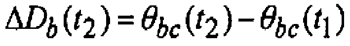
 - la variation de facteur de perte de la troisième traversée de condensateur (2c) est calculée selon la formule suivante
 - Ra(t1), Rb(t1), Rc(t1) étant les premiers vecteurs de tension de référence des première, deuxième et troisième phases ;- Va(t1), Vb(t1), Vc(t1) étant les premiers vecteurs de tension d'armature des première, deuxième et troisième phases ;- Ra(t2), Rb(t2), Rc(t2) étant les deuxièmes vecteurs de tension de référence des première, deuxième et troisième phases ;- Va(t2), Vb(t2), Vc(t2) étant les deuxièmes vecteurs de tension d'armature des première, deuxième et troisième phases,• la variation du facteur de perte étant comparée à une valeur de tolérance (DA, DB, DC) ;- un signal de surveillance étant généré en fonction des résultats de ces comparaisons de facteurs de perte.
 - Procédé selon l'une des revendications précédentes,- chaque tension de référence étant la tension de réseau respective (Ua(t1), Ua(t2), Ub(t1), Ub(t2), Uc(t1), Uc(t2)) .
- Procédé selon la revendication 1,- la première ligne de réseau (5a) étant associée à une traversée de condensateur parallèle (2a') ;- la deuxième ligne de réseau (5b) étant associée à une deuxième traversée de condensateur parallèle (2b') ;- la troisième ligne de réseau (5c) étant associée à une troisième traversée de condensateur parallèle (2c') ;- chacune de ces traversées de condensateur parallèles (2a', 2b', 2c') comprenant• un conducteur (4) qui est relié à la ligne de réseau associée (5a, 5b, 5c),• une armature électriquement conductrice (3) qui entoure ce conducteur (4) ;- pour chacune de ces phases (A, B, C)• les première et deuxième tensions de référence étant des première et deuxième tensions d'armature (Va' (t1), Vb' (t1), Vc'(t1), Va'(t2), Vb'(t2), Vc'(t2)), qui sont appliquées au premier instant et au deuxième instant entre l'armature (3) et le potentiel de masse (13) de la traversée de condensateur parallèle respective.
- Procédé selon la revendication 1 ou l'une des revendications précédentes,- pour chacune de ces phases (A, B, C)• la tension de référence étant une tension constante pour laquelle un vecteur de tension constante correspondant est prédéterminé.
- Procédé selon la revendication précédente,- l'intensité de chaque vecteur de tension constante étant égale à une valeur de tension nominale du réseau à courant alternatif ;- pour la première phase (A), l'angle de phase des premier et deuxième vecteurs de tension constante (Ra(t1), Ra(t2)) étant de 0° ;- pour la deuxième phase (B), l'angle de phase des premier et deuxième vecteurs de tension constante (Rb(t1), Rb(t2)) étant de 120° ;- pour la troisième phase (C), l'angle de phase des premier et deuxième vecteurs de tension constante (Rc(t1), Rc(t2)) étant de 240°.
- Procédé selon l'une des revendications précédentes,- des valeurs de tolérance DA > 0, DB > 0, DC > 0 étant déterminées pour les comparaisons de facteur de perte ;- si les comparaisons des facteurs de perte montrent que l'on a

- Procédé selon l'une des revendications précédentes,- des valeurs de tolérance DA > 0, DB > 0, DC > 0 étant déterminées pour les comparaisons de facteurs de perte ;- si les comparaisons de facteurs de perte montrent que l'on a
 - si les comparaisons de facteurs de perte montrent que l'on a
 - si les comparaisons de facteurs de perte montrent que l'on a
- Procédé selon la revendication précédente,- sinon, un signal de surveillance étant généré qui indique que les trois traversées de condensateur (2a, 2b, 2c) ne sont pas en bon état ou que deux traversées de condensateur ne sont pas en bon état et ne présentent pas de défaut similaire.
- Procédé selon l'une des revendications précédentes,- à un troisième instant prédéterminé (t3), qui est postérieur au deuxième instant (t2), pour chacune de ces phases (A, B, C)• un troisième vecteur de tension de référence correspondant (Ra(t3), Rb(t3), Rc(t3)) étant déterminé pour une tension de référence ;• la tension d'armature étant détectée et un troisième vecteur de tension d'armature correspondant (Va(t3), Vb(t3), Vc(t3)) étant déterminé ;• le deuxième vecteur de tension de référence étant remplacé par le troisième vecteur de tension de référence et le deuxième vecteur de tension d'armature étant remplacé par le troisième vecteur de tension d'armature ;- pour chacune de ces traversées de condensateur (2a, 2b, 2c)• le calcul et la comparaison de la variation de facteur de perte (ΔDa, ΔDb, ΔDc) étant répétés ;- un signal de surveillance étant généré en fonction des résultats de ces comparaisons de facteurs de perte.
- Procédé selon la revendication précédente,- avant chaque remplacement des deuxièmes vecteur de tension de référence et vecteur de tension d'armature,• le premier vecteur tension de référence étant remplacé par le deuxième vecteur de tension de référence et le premier vecteur de tension d'armature étant remplacé par le deuxième vecteur de tension d'armature.
- Procédé selon l'une des revendications précédentes,- au moins à un instant ultérieur prédéterminé (tn), qui est postérieur au deuxième instant (t2), pour chacune de ces phases (A, B, C)• un vecteur de tension de référence ultérieur correspondant (Ra(tn), Rb(tn), Rc(tn)) étant déterminé pour une tension de référence ;• la tension d'armature étant détectée et un vecteur de tension d'armature ultérieur correspondant (Va(tn), Vb(tn), Vc(tn)) étant déterminé ;- pour chacune de ces traversées de condensateur (2a, 2b, 2c)• le calcul de la variation de facteur de perte (ΔDa, ΔDb, ΔDc) dépendant également des vecteurs tension de réseau et vecteurs de tension d'armature ultérieurs.
- Procédé selon l'une des revendications précédentes,- au moins à un instant ultérieur prédéterminé (tn), qui est postérieur au deuxième instant (t2), pour chacune de ces phases (A, B, C)• un vecteur tension de référence ultérieur (Ra(tn), Rb(tn), Rc(tn)) étant déterminé ;• la tension d'armature étant détectée et un vecteur de tension d'armature ultérieur correspondant (Va(tn), Vb(tn), Vc(tn)) étant déterminé ;- pour chacune de ces traversées de condensateur (2a, 2b, 2c)• une variation de facteur de perte (ΔDa, ΔDb, ΔDc) étant calculée en fonction des premiers et deuxièmes vecteurs de tension de référence et vecteurs de tension d'armature respectifs et les suivants ainsi que des premiers et deuxièmes vecteurs de tension de référence et vecteurs de tension d'armature et les suivants de la traversée de condensateur adjacente (2b, 2c, 2a) ;• la variation de facteur de perte étant comparée à une valeur de tolérance (DA, DB, DC) ;- un signal de surveillance étant généré en fonction des résultats de ces comparaisons de facteurs de perte.
- Procédé selon l'une des 2 revendications précédentes,- la variation de facteur de perte de la première traversée de condensateur (2a) étant calculée selon la formule suivante


 - la variation de facteur de perte de la deuxième traversée de condensateur (2b) étant calculée selon la formule suivante
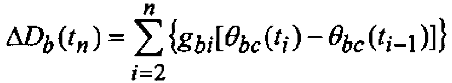

 - la variation de facteur de perte de la troisième traversée de condensateur (2c) étant calculée selon la formule suivante
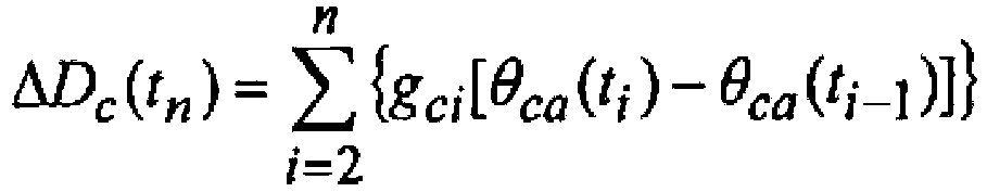

 - n > 2 étant le nombre d'instants ;- t1, t2 étant les premier et deuxième instants et t3, ..., tn étant les instants ultérieurs ;- gai, gbi, gci étant les i-ièmes facteurs de pondération pour les première, deuxième et troisième traversées de condensateur.
 - Procédé selon la revendication précédente,- chaque facteur de pondération dépendant de l'ancienneté de l'instant respectif de manière antitonale ; et/ou- pour les facteurs de pondération

- Procédé selon l'une des revendications précédentes,- entre la détermination du premier vecteur de tension de référence et la détermination du premier vecteur de tension d'armature• les intensités des premiers vecteurs tension de référence étant comparées entre elles,• la détermination du premier vecteur de tension d'armature étant effectuée si ces comparaisons d'intensités montrent que ces intensités ne diffèrent pas l'une de l'autre de plus d'une valeur prédéterminée ;et/ou- entre la détermination du deuxième vecteur de tension de référence et la détermination du deuxième vecteur de tension d'armature• les intensités des deuxièmes vecteurs de tension de référence étant comparées entre elles,• la détermination du deuxième vecteur de tension d'armature étant effectuée si ces comparaisons d'intensités montrent que ces intensités ne diffèrent pas l'une de l'autre de plus d'une valeur prédéterminée.
- Procédé selon l'une des revendications précédentes,- entre la détermination du premier vecteur de tension de référence et la détermination du premier vecteur de tension d'armature• les angles de phase des premiers vecteurs de tension de référence étant comparés entre eux,• la détermination des premiers vecteurs de tension d'armature étant effectuée si ces comparaisons d'angles montrent que ces angles de phase ne diffèrent pas l'un de l'autre de plus d'une valeur prédéterminée ;- entre la détermination du deuxième vecteur de tension de référence et la détermination du deuxième vecteur de tension d'armature• les angles de phase des deuxièmes vecteurs de tension de référence étant comparés entre eux,• la détermination du deuxième vecteur de tension d'armature étant effectuée si ces comparaisons d'angles montrent que ces angles de phase ne diffèrent pas l'un de l'autre de plus d'une valeur prédéterminée.
- Dispositif (1) de surveillance de traversées de condensateur (2a, 2b, 2c) destiné à un réseau à courant alternatif,- le réseau à courant alternatif comportant des première, deuxième et troisième phases (A, B, C) et comprenant• une première ligne de réseau (5a) à laquelle sont associées la première phase (A) et une première traversée de condensateur (2a) et à laquelle est appliquée une première tension de réseau,• une deuxième ligne de réseau (5b) à laquelle sont associées la deuxième phase (B) et une deuxième traversée de condensateur (2b) et à laquelle est appliquée une deuxième tension de réseau,• une troisième ligne de réseau (5c) à laquelle sont associées la troisième phase (C) et une troisième traversée de condensateur (2c) et à laquelle est appliquée une troisième tension de réseau ;- chacune de ces traversées de condensateur (2a, 2b, 2c) comprenant• un conducteur (4) qui est relié à la ligne de réseau associée (5a, 5b, 5c) ;• une armature électriquement conductrice (3) entourant ce conducteur (4) ;- le dispositif comprenant :• un premier convertisseur de tension (9a) qui peut être relié à la première ligne de réseau (5a) ;• un deuxième convertisseur de tension (9b) qui peut être relié à la deuxième ligne de réseau (5b) ;• un troisième convertisseur de tension (9c) qui peut être relié à la troisième ligne de réseau (5c) ;• un premier adaptateur de mesure (6a) qui peut être relié à l'armature (3) de la première traversée de condensateur (2a) ;• un deuxième adaptateur de mesure (6b) qui peut être relié à l'armature (3) de la deuxième traversée de condensateur (2b) ;• un troisième adaptateur de mesure (6c) qui peut être relié à l'armature (3) de la troisième traversée de condensateur (2c) ;• une unité de mesure (7) qui est accouplée aux adaptateurs de mesure (6a, 6b, 6c) ;• une unité d'évaluation (8) qui est accouplée aux convertisseurs de tension (9a, 9b, 9c) et à l'unité de mesure (7) ;- chacun de ces convertisseurs de tension (9a, 9b, 9c) destiné à la phase respective (A, B, C) pouvant détecter la tension de réseau ;- l'unité de mesure (7) destinée à chacune de ces phases (A, B, C) pouvant détecter une tension d'armature, qui est appliquée entre l'armature respective (3) et le potentiel de terre (13), à l'aide de l'adaptateur de mesure respectif (6a, 6b, 6c) ;- l'unité d'évaluation (8) étant conçue de manière à ce qu'à un premier instant prédéterminé (t1) pour chacune de ces phases (A, B, C)• le convertisseur de tension respectif (9a, 9b, 9c) soit utilisé pour détecter la tension de réseau et déterminer un premier vecteur de tension de réseau correspondant (Ua(t1), Ub(t1), Uct1)) ;• l'unité de mesure (7) soit utilisée pour détecter la tension d'armature et déterminer un premier vecteur de tension d'armature correspondant (Va(t1), Vb(t1), Vc(t1)) ;- l'unité d'évaluation (8) étant conçue de manière à ce qu'à un deuxième instant prédéterminé (t2), qui est postérieur au premier instant (t1), pour chacune de ces phases (A, B, C)• le convertisseur de tension respectif (9a, 9b, 9c) soit utilisé pour détecter la tension de réseau et déterminer un deuxième vecteur de tension de réseau correspondant (Ua(t2), Ub(t2), Uc(t2)) ;• l'unité de mesure (7) soit utilisée pour détecter la tension d'armature et déterminer un deuxième vecteur de tension d'armature correspondant (Va(t2), Vb(t2), Vc(t2)) ;caractérisé en ce que- l'unité d'évaluation (8) est conçue de manière à, pour chacune de ces traversées de condensateur (2a, 2b, 2c),• pouvoir calculer une variation de facteur de perte (ΔDa, ΔDb, ΔDc) en fonction des premiers et deuxièmes vecteurs de tension de réseau et vecteurs de tension d'armature respectifs ainsi que des premiers et deuxièmes vecteurs de tension de réseau et vecteurs de tension d'armature de la traversée de condensateur respectivement adjacente (2b, 2c, 2a) ;• pouvoir comparer la variation de facteur de perte à une valeur de tolérance (DA, DB, DC) ;- l'unité d'évaluation (8) est conçue de manière à pouvoir générer un signal de surveillance en fonction des résultats de ces comparaisons de facteur de perte ; par lequel- la variation de facteur de perte de la première traversée de condensateur (2a) est calculée selon la formule suivante

 - la variation de facteur de perte de la deuxième traversée de condensateur (2b) est calculée selon la formule suivante
 - la variation de facteur de perte de la troisième traversée de condensateur (2c) est calculée selon la formule suivante
 - Ra(t1), Rb(t1), Rc(t1) étant les premiers vecteurs de tension de référence des première, deuxième et troisième phases ;- Va(t1), Vb(t1), Vc(t1) étant les premiers vecteurs d'armature des première, deuxième et troisième phases ;- Ra(t2), Rb(t2), Rc(t2) étant les deuxièmes vecteurs de tension de référence des première, deuxième et troisième phases ;- Va(t2), Vb(t2), Vc(t2) étant les deuxièmes vecteurs de tension d'armature des première, deuxième et troisième phases.
Applications Claiming Priority (2)
| Application Number | Priority Date | Filing Date | Title |
|---|---|---|---|
| DE102017104110.9A DE102017104110B4 (de) | 2017-02-28 | 2017-02-28 | Verfahren und Vorrichtung zur Verlustfaktorüberwachung von Kondensatordurchführungen |
| PCT/EP2018/054398 WO2018158135A1 (fr) | 2017-02-28 | 2018-02-22 | Procédé et dispositif pour surveiller les facteurs de pertes de traversées de condensateurs |
Publications (2)
| Publication Number | Publication Date |
|---|---|
| EP3589964A1 EP3589964A1 (fr) | 2020-01-08 |
| EP3589964B1 true EP3589964B1 (fr) | 2023-01-25 |
Family
ID=61563360
Family Applications (1)
| Application Number | Title | Priority Date | Filing Date |
|---|---|---|---|
| EP18708621.0A Active EP3589964B1 (fr) | 2017-02-28 | 2018-02-22 | Procédé et dispositif pour surveiller les facteurs de pertes de traversées de condensateurs |
Country Status (8)
| Country | Link |
|---|---|
| US (1) | US11125801B2 (fr) |
| EP (1) | EP3589964B1 (fr) |
| JP (1) | JP7084411B2 (fr) |
| KR (1) | KR102533001B1 (fr) |
| CN (1) | CN110337593B (fr) |
| DE (1) | DE102017104110B4 (fr) |
| RU (1) | RU2765885C2 (fr) |
| WO (1) | WO2018158135A1 (fr) |
Families Citing this family (5)
| Publication number | Priority date | Publication date | Assignee | Title |
|---|---|---|---|---|
| EP3650872B1 (fr) * | 2018-11-08 | 2021-06-09 | ABB Power Grids Switzerland AG | Procédé de paramètres de traversée relatifs pour éviter l'influence de la température dans la surveillance de paramètre de traversée absolus d'un transformateur |
| US11226359B2 (en) * | 2019-10-31 | 2022-01-18 | Ravisekhar Nadimpalli Raju | System and method to generate multi-level voltage pulses for electrical insulation testing |
| CN112578187B (zh) * | 2020-11-23 | 2022-02-08 | 清华大学 | 高频变压器损耗测量系统和方法 |
| CN112798871B (zh) * | 2020-12-07 | 2023-03-14 | 广西电网有限责任公司电力科学研究院 | 一种油纸绝缘电容型套管介损值异常现场原因处理的方法 |
| CN113030776B (zh) * | 2021-03-31 | 2022-05-17 | 中国南方电网有限责任公司超高压输电公司检修试验中心 | 柔性直流穿墙套管监控装置、监测方法及故障判断方法 |
Family Cites Families (26)
| Publication number | Priority date | Publication date | Assignee | Title |
|---|---|---|---|---|
| DE2325440A1 (de) * | 1973-05-17 | 1974-11-21 | Siemens Ag | Messwandler mit einer kondensatordurchfuehrung |
| JPS5627830B2 (fr) * | 1973-12-27 | 1981-06-27 | ||
| US4757263A (en) * | 1987-05-01 | 1988-07-12 | Tennessee Valley Authority | Insulation power factor alarm monitor |
| DE19519230C1 (de) * | 1995-05-24 | 1996-11-28 | Hsp Hochspannungsgeraete Porz | Überwachungsverfahren für eine Kondensatordurchführung und eine Überwachungsanordnung hierzu |
| US6177803B1 (en) | 1995-06-07 | 2001-01-23 | Doble Engineering Company | Monitoring elements in a multi-phase alternating current network |
| DE19912410A1 (de) * | 1999-03-19 | 2000-10-12 | Reinhausen Maschf Scheubeck | Meßverfahren für eine Hochspannungsdurchführung und geeignete Meßanordnung |
| EP1264191B1 (fr) * | 2000-03-14 | 2005-07-06 | HSP Hochspannungsgeräte Porz GmbH | Dispositif et procede pour surveiller une traversee de condensateur |
| DE10012068A1 (de) | 2000-03-14 | 2001-10-04 | Hsp Hochspannungsgeraete Porz | Vorrichtung und Verfahren zur Überwachung einer Kondensatordurchführung |
| CN1232831C (zh) * | 2004-05-17 | 2005-12-21 | 西安交通大学 | 电容型电力设备介质损耗在线监测方法及装置 |
| RU2265860C1 (ru) * | 2004-05-18 | 2005-12-10 | Закрытое акционерное общество "Саратовское предприятие промышленной электроники и энергетики" (ЗАО "Промэлектроника") | Устройство для контроля состояния трехфазного оборудования с бумажно-масляной изоляцией конденсаторного типа |
| DE102004027349B4 (de) | 2004-05-27 | 2008-05-29 | Siemens Ag | Prüfanordnuung und Verfahren zum Ermitteln des Verlustfaktors einer Hochspannungsdurchführung |
| JP2007333529A (ja) * | 2006-06-14 | 2007-12-27 | Tokyo Weld Co Ltd | 絶縁抵抗測定装置、漏洩電流測定装置、絶縁抵抗測定方法および漏洩電流測定方法 |
| KR101064202B1 (ko) * | 2010-12-15 | 2011-09-14 | (주)엘레시스 | 변압기의 부싱 건전성을 모니터링하는 방법 및 장치 |
| CN102156250A (zh) * | 2011-03-17 | 2011-08-17 | 华北电力大学(保定) | 一种基于等效模型的介质损耗因数测量方法 |
| DE102012016686A1 (de) | 2012-08-24 | 2014-05-15 | Michael Rösner | Verfahren und Vorrichtung zur Messung von dielektrischen Kenngrößen der Isolation von Hochspannungsgeräten |
| CN102981062B (zh) * | 2012-12-20 | 2015-03-25 | 国网电力科学研究院武汉南瑞有限责任公司 | 一种基于频域介电谱的高压套管绝缘检测方法 |
| CN203278012U (zh) * | 2013-04-27 | 2013-11-06 | 无锡赛晶电力电容器有限公司 | 一种智能型柜式无功补偿装置 |
| CN104215842B (zh) * | 2013-06-03 | 2016-09-28 | 国家电网公司 | 一种基于套管的变压器在线监测系统 |
| DE102013112584B4 (de) * | 2013-11-15 | 2017-12-14 | Maschinenfabrik Reinhausen Gmbh | Verfahren und Vorrichtung zur Überwachung von Kondensatordurchführungen für ein dreiphasiges Wechselstromnetz |
| CN104122490A (zh) | 2014-07-16 | 2014-10-29 | 国家电网公司 | 一种变压器套管绝缘状态在线监测装置及方法 |
| US9945896B2 (en) | 2014-12-01 | 2018-04-17 | Joe David Watson | Active monitoring systems for high voltage bushings and methods related thereto |
| EP3070483B1 (fr) | 2015-03-17 | 2017-09-13 | ABB Schweiz AG | Procédé de surveillance de douilles de transformateurs et système permettant la mise en oeuvre de celui-ci |
| CN104849568B (zh) * | 2015-05-14 | 2016-06-01 | 广东电网有限责任公司电力科学研究院 | 基于信号调节的变压器套管监测装置检测平台 |
| CN104897974A (zh) * | 2015-06-18 | 2015-09-09 | 江苏理工学院 | 一种容性设备介质损耗测量方法及系统 |
| CN105588985A (zh) * | 2016-03-18 | 2016-05-18 | 国网上海市电力公司 | 一种基于相位因子变换插值的介损在线精确测量方法 |
| DE102017104109A1 (de) * | 2017-02-28 | 2018-08-30 | Maschinenfabrik Reinhausen Gmbh | Verfahren und Vorrichtung zur Überwachung von Kondensatordurchführungen für ein Wechselstromnetz |
-
2017
- 2017-02-28 DE DE102017104110.9A patent/DE102017104110B4/de active Active
-
2018
- 2018-02-22 EP EP18708621.0A patent/EP3589964B1/fr active Active
- 2018-02-22 US US16/487,444 patent/US11125801B2/en active Active
- 2018-02-22 CN CN201880014219.3A patent/CN110337593B/zh active Active
- 2018-02-22 RU RU2019129605A patent/RU2765885C2/ru active
- 2018-02-22 WO PCT/EP2018/054398 patent/WO2018158135A1/fr unknown
- 2018-02-22 KR KR1020197026344A patent/KR102533001B1/ko active IP Right Grant
- 2018-02-22 JP JP2019546917A patent/JP7084411B2/ja active Active
Also Published As
| Publication number | Publication date |
|---|---|
| RU2019129605A (ru) | 2021-03-30 |
| CN110337593A (zh) | 2019-10-15 |
| DE102017104110B4 (de) | 2019-03-28 |
| US11125801B2 (en) | 2021-09-21 |
| EP3589964A1 (fr) | 2020-01-08 |
| JP7084411B2 (ja) | 2022-06-14 |
| RU2019129605A3 (fr) | 2021-07-05 |
| CN110337593B (zh) | 2022-05-31 |
| RU2765885C2 (ru) | 2022-02-04 |
| KR20190118604A (ko) | 2019-10-18 |
| DE102017104110A1 (de) | 2018-08-30 |
| BR112019017290A2 (pt) | 2020-04-14 |
| US20200057103A1 (en) | 2020-02-20 |
| KR102533001B1 (ko) | 2023-05-15 |
| WO2018158135A1 (fr) | 2018-09-07 |
| JP2020509377A (ja) | 2020-03-26 |
Similar Documents
| Publication | Publication Date | Title |
|---|---|---|
| EP3589964B1 (fr) | Procédé et dispositif pour surveiller les facteurs de pertes de traversées de condensateurs | |
| EP3069359B1 (fr) | Procédé et dispositif de surveillance de condensateurs de traversée pour réseau de courant alternatif triphasé | |
| EP1909368B1 (fr) | Agencement de commutation et procédé de surveillance d'isolation pour des applications de convertisseur | |
| DE102017009355A1 (de) | Verfahren zum Betreiben von elektrischen Bordnetzen | |
| EP3417523B1 (fr) | Procédé de commande d'un transformateur de régulation et installation électrique de couplage de deux réseaux à courant alternatif | |
| WO2010106059A1 (fr) | Procédé et dispositif de contrôle de l'isolement d'un réseau it | |
| EP3589963B1 (fr) | Procédé et dispositif de surveillance de passages de condensateur pour un réseau à courant alternatif | |
| EP3857667A1 (fr) | Procédé et dispositif d'identification d'une affectation de lignes de phase aux raccordements d'un appareil électrique apte au déséquilibre de charge | |
| EP3308179B1 (fr) | Dispositif de commutation, dispositif de test et procédé pour faire fonctionner un dispositif de commutation pour un appareil de mesure pour un transformateur | |
| EP3776612B1 (fr) | Batterie de condensateurs | |
| DE102014103321A1 (de) | Isolationsüberwachung für reihenkompensierte Wicklungen eines kontaktlosen Energieübertragungssystems | |
| WO2001069272A2 (fr) | Dispositif et procede pour surveiller une traversee de condensateur | |
| DE102016100671A1 (de) | Verfahren und Vorrichtung zur Kurzschlussüberwachung einer Drehstromlast | |
| EP2651020B1 (fr) | Convertisseur de tension | |
| WO2019174869A1 (fr) | Mesure d'harmoniques dans les réseaux électriques | |
| DE102009048509A1 (de) | Verfahren und Vorrichtung zur Ermittlung einer Eingangsspannung an einer Ortsnetzstation eines Stromnetzes | |
| DE102011082554B4 (de) | Verfahren zur Bestimmung eines Erdschlussstroms in einem erdschlussbehafteten Drehstromnetz | |
| DE102019129413B4 (de) | Kompensationsvorrichtung für Ableitströme | |
| EP0745862A2 (fr) | Procédé et appareil pour déterminer les propriétés d'isolation d'objets à examiner | |
| EP1341284B1 (fr) | Test de validité pour les transformateurs de tension dans les sous-stations de distribution d'energie | |
| EP1772738A2 (fr) | Procédé de diagnostic du vieillissement d'installations électriques utilisant des mesures de facteur de perte à des fréquences plus basses que les fréquences des réseaux électriques publics | |
| CH619545A5 (fr) | ||
| DE102019105861A1 (de) | Verfahren und Vorrichtung zur näherungsweisen Bestimmung von Spannungen an einer Oberspannungsseite eines Transformators | |
| DE102016217076B4 (de) | Kapazitiver Spannungswandler für Hoch- und Mittelspannungen und Verfahren zum Herstellen eines kapazitiven Spannungswandlers | |
| DE102012205610A1 (de) | Verfahren zur Parametrierung eines Spannungsmessgerätes und damit parametrierbares Spannungsmessgerät |
Legal Events
| Date | Code | Title | Description |
|---|---|---|---|
| STAA | Information on the status of an ep patent application or granted ep patent |
Free format text: STATUS: UNKNOWN |
|
| STAA | Information on the status of an ep patent application or granted ep patent |
Free format text: STATUS: THE INTERNATIONAL PUBLICATION HAS BEEN MADE |
|
| PUAI | Public reference made under article 153(3) epc to a published international application that has entered the european phase |
Free format text: ORIGINAL CODE: 0009012 |
|
| STAA | Information on the status of an ep patent application or granted ep patent |
Free format text: STATUS: REQUEST FOR EXAMINATION WAS MADE |
|
| 17P | Request for examination filed |
Effective date: 20190930 |
|
| AK | Designated contracting states |
Kind code of ref document: A1 Designated state(s): AL AT BE BG CH CY CZ DE DK EE ES FI FR GB GR HR HU IE IS IT LI LT LU LV MC MK MT NL NO PL PT RO RS SE SI SK SM TR |
|
| AX | Request for extension of the european patent |
Extension state: BA ME |
|
| DAV | Request for validation of the european patent (deleted) | ||
| DAX | Request for extension of the european patent (deleted) | ||
| REG | Reference to a national code |
Ref country code: HK Ref legal event code: DE Ref document number: 40013664 Country of ref document: HK |
|
| RIC1 | Information provided on ipc code assigned before grant |
Ipc: G01R 15/06 20060101ALN20220727BHEP Ipc: G01R 31/62 20200101ALN20220727BHEP Ipc: G01R 31/64 20200101ALI20220727BHEP Ipc: G01R 27/26 20060101ALI20220727BHEP Ipc: G01R 31/12 20200101AFI20220727BHEP |
|
| GRAP | Despatch of communication of intention to grant a patent |
Free format text: ORIGINAL CODE: EPIDOSNIGR1 |
|
| STAA | Information on the status of an ep patent application or granted ep patent |
Free format text: STATUS: GRANT OF PATENT IS INTENDED |
|
| RIC1 | Information provided on ipc code assigned before grant |
Ipc: G01R 15/06 20060101ALN20220824BHEP Ipc: G01R 31/62 20200101ALN20220824BHEP Ipc: G01R 31/64 20200101ALI20220824BHEP Ipc: G01R 27/26 20060101ALI20220824BHEP Ipc: G01R 31/12 20200101AFI20220824BHEP |
|
| INTG | Intention to grant announced |
Effective date: 20220920 |
|
| GRAS | Grant fee paid |
Free format text: ORIGINAL CODE: EPIDOSNIGR3 |
|
| GRAA | (expected) grant |
Free format text: ORIGINAL CODE: 0009210 |
|
| STAA | Information on the status of an ep patent application or granted ep patent |
Free format text: STATUS: THE PATENT HAS BEEN GRANTED |
|
| AK | Designated contracting states |
Kind code of ref document: B1 Designated state(s): AL AT BE BG CH CY CZ DE DK EE ES FI FR GB GR HR HU IE IS IT LI LT LU LV MC MK MT NL NO PL PT RO RS SE SI SK SM TR |
|
| REG | Reference to a national code |
Ref country code: GB Ref legal event code: FG4D Free format text: NOT ENGLISH |
|
| REG | Reference to a national code |
Ref country code: CH Ref legal event code: EP |
|
| REG | Reference to a national code |
Ref country code: DE Ref legal event code: R096 Ref document number: 502018011502 Country of ref document: DE |
|
| REG | Reference to a national code |
Ref country code: AT Ref legal event code: REF Ref document number: 1546248 Country of ref document: AT Kind code of ref document: T Effective date: 20230215 Ref country code: IE Ref legal event code: FG4D Free format text: LANGUAGE OF EP DOCUMENT: GERMAN |
|
| PGFP | Annual fee paid to national office [announced via postgrant information from national office to epo] |
Ref country code: AT Payment date: 20230301 Year of fee payment: 6 |
|
| REG | Reference to a national code |
Ref country code: LT Ref legal event code: MG9D |
|
| PGFP | Annual fee paid to national office [announced via postgrant information from national office to epo] |
Ref country code: GB Payment date: 20230228 Year of fee payment: 6 |
|
| REG | Reference to a national code |
Ref country code: NL Ref legal event code: MP Effective date: 20230125 |
|
| PG25 | Lapsed in a contracting state [announced via postgrant information from national office to epo] |
Ref country code: NL Free format text: LAPSE BECAUSE OF FAILURE TO SUBMIT A TRANSLATION OF THE DESCRIPTION OR TO PAY THE FEE WITHIN THE PRESCRIBED TIME-LIMIT Effective date: 20230125 |
|
| PG25 | Lapsed in a contracting state [announced via postgrant information from national office to epo] |
Ref country code: RS Free format text: LAPSE BECAUSE OF FAILURE TO SUBMIT A TRANSLATION OF THE DESCRIPTION OR TO PAY THE FEE WITHIN THE PRESCRIBED TIME-LIMIT Effective date: 20230125 Ref country code: PT Free format text: LAPSE BECAUSE OF FAILURE TO SUBMIT A TRANSLATION OF THE DESCRIPTION OR TO PAY THE FEE WITHIN THE PRESCRIBED TIME-LIMIT Effective date: 20230525 Ref country code: NO Free format text: LAPSE BECAUSE OF FAILURE TO SUBMIT A TRANSLATION OF THE DESCRIPTION OR TO PAY THE FEE WITHIN THE PRESCRIBED TIME-LIMIT Effective date: 20230425 Ref country code: LV Free format text: LAPSE BECAUSE OF FAILURE TO SUBMIT A TRANSLATION OF THE DESCRIPTION OR TO PAY THE FEE WITHIN THE PRESCRIBED TIME-LIMIT Effective date: 20230125 Ref country code: LT Free format text: LAPSE BECAUSE OF FAILURE TO SUBMIT A TRANSLATION OF THE DESCRIPTION OR TO PAY THE FEE WITHIN THE PRESCRIBED TIME-LIMIT Effective date: 20230125 Ref country code: HR Free format text: LAPSE BECAUSE OF FAILURE TO SUBMIT A TRANSLATION OF THE DESCRIPTION OR TO PAY THE FEE WITHIN THE PRESCRIBED TIME-LIMIT Effective date: 20230125 Ref country code: ES Free format text: LAPSE BECAUSE OF FAILURE TO SUBMIT A TRANSLATION OF THE DESCRIPTION OR TO PAY THE FEE WITHIN THE PRESCRIBED TIME-LIMIT Effective date: 20230125 |
|
| PGFP | Annual fee paid to national office [announced via postgrant information from national office to epo] |
Ref country code: IT Payment date: 20230512 Year of fee payment: 6 |
|
| PG25 | Lapsed in a contracting state [announced via postgrant information from national office to epo] |
Ref country code: SE Free format text: LAPSE BECAUSE OF FAILURE TO SUBMIT A TRANSLATION OF THE DESCRIPTION OR TO PAY THE FEE WITHIN THE PRESCRIBED TIME-LIMIT Effective date: 20230125 Ref country code: PL Free format text: LAPSE BECAUSE OF FAILURE TO SUBMIT A TRANSLATION OF THE DESCRIPTION OR TO PAY THE FEE WITHIN THE PRESCRIBED TIME-LIMIT Effective date: 20230125 Ref country code: IS Free format text: LAPSE BECAUSE OF FAILURE TO SUBMIT A TRANSLATION OF THE DESCRIPTION OR TO PAY THE FEE WITHIN THE PRESCRIBED TIME-LIMIT Effective date: 20230525 Ref country code: GR Free format text: LAPSE BECAUSE OF FAILURE TO SUBMIT A TRANSLATION OF THE DESCRIPTION OR TO PAY THE FEE WITHIN THE PRESCRIBED TIME-LIMIT Effective date: 20230426 Ref country code: FI Free format text: LAPSE BECAUSE OF FAILURE TO SUBMIT A TRANSLATION OF THE DESCRIPTION OR TO PAY THE FEE WITHIN THE PRESCRIBED TIME-LIMIT Effective date: 20230125 |
|
| REG | Reference to a national code |
Ref country code: DE Ref legal event code: R119 Ref document number: 502018011502 Country of ref document: DE |
|
| REG | Reference to a national code |
Ref country code: CH Ref legal event code: PL |
|
| REG | Reference to a national code |
Ref country code: BE Ref legal event code: MM Effective date: 20230228 |
|
| PG25 | Lapsed in a contracting state [announced via postgrant information from national office to epo] |
Ref country code: SM Free format text: LAPSE BECAUSE OF FAILURE TO SUBMIT A TRANSLATION OF THE DESCRIPTION OR TO PAY THE FEE WITHIN THE PRESCRIBED TIME-LIMIT Effective date: 20230125 Ref country code: RO Free format text: LAPSE BECAUSE OF FAILURE TO SUBMIT A TRANSLATION OF THE DESCRIPTION OR TO PAY THE FEE WITHIN THE PRESCRIBED TIME-LIMIT Effective date: 20230125 Ref country code: MC Free format text: LAPSE BECAUSE OF FAILURE TO SUBMIT A TRANSLATION OF THE DESCRIPTION OR TO PAY THE FEE WITHIN THE PRESCRIBED TIME-LIMIT Effective date: 20230125 Ref country code: LU Free format text: LAPSE BECAUSE OF NON-PAYMENT OF DUE FEES Effective date: 20230222 Ref country code: LI Free format text: LAPSE BECAUSE OF NON-PAYMENT OF DUE FEES Effective date: 20230228 Ref country code: EE Free format text: LAPSE BECAUSE OF FAILURE TO SUBMIT A TRANSLATION OF THE DESCRIPTION OR TO PAY THE FEE WITHIN THE PRESCRIBED TIME-LIMIT Effective date: 20230125 Ref country code: DK Free format text: LAPSE BECAUSE OF FAILURE TO SUBMIT A TRANSLATION OF THE DESCRIPTION OR TO PAY THE FEE WITHIN THE PRESCRIBED TIME-LIMIT Effective date: 20230125 Ref country code: CZ Free format text: LAPSE BECAUSE OF FAILURE TO SUBMIT A TRANSLATION OF THE DESCRIPTION OR TO PAY THE FEE WITHIN THE PRESCRIBED TIME-LIMIT Effective date: 20230125 Ref country code: CH Free format text: LAPSE BECAUSE OF NON-PAYMENT OF DUE FEES Effective date: 20230228 |
|
| PG25 | Lapsed in a contracting state [announced via postgrant information from national office to epo] |
Ref country code: SK Free format text: LAPSE BECAUSE OF FAILURE TO SUBMIT A TRANSLATION OF THE DESCRIPTION OR TO PAY THE FEE WITHIN THE PRESCRIBED TIME-LIMIT Effective date: 20230125 Ref country code: AL Free format text: LAPSE BECAUSE OF FAILURE TO SUBMIT A TRANSLATION OF THE DESCRIPTION OR TO PAY THE FEE WITHIN THE PRESCRIBED TIME-LIMIT Effective date: 20230125 |
|
| PLBE | No opposition filed within time limit |
Free format text: ORIGINAL CODE: 0009261 |
|
| STAA | Information on the status of an ep patent application or granted ep patent |
Free format text: STATUS: NO OPPOSITION FILED WITHIN TIME LIMIT |
|
| REG | Reference to a national code |
Ref country code: IE Ref legal event code: MM4A |
|
| 26N | No opposition filed |
Effective date: 20231026 |
|
| PG25 | Lapsed in a contracting state [announced via postgrant information from national office to epo] |
Ref country code: SI Free format text: LAPSE BECAUSE OF FAILURE TO SUBMIT A TRANSLATION OF THE DESCRIPTION OR TO PAY THE FEE WITHIN THE PRESCRIBED TIME-LIMIT Effective date: 20230125 Ref country code: IE Free format text: LAPSE BECAUSE OF NON-PAYMENT OF DUE FEES Effective date: 20230222 Ref country code: FR Free format text: LAPSE BECAUSE OF NON-PAYMENT OF DUE FEES Effective date: 20230325 Ref country code: DE Free format text: LAPSE BECAUSE OF NON-PAYMENT OF DUE FEES Effective date: 20230901 |
|
| PG25 | Lapsed in a contracting state [announced via postgrant information from national office to epo] |
Ref country code: BE Free format text: LAPSE BECAUSE OF NON-PAYMENT OF DUE FEES Effective date: 20230228 |
|
| PGFP | Annual fee paid to national office [announced via postgrant information from national office to epo] |
Ref country code: AT Payment date: 20240216 Year of fee payment: 7 |
|
| PGFP | Annual fee paid to national office [announced via postgrant information from national office to epo] |
Ref country code: GB Payment date: 20240222 Year of fee payment: 7 |