EP3589873B1 - Schlauchbefestigungsanordnung - Google Patents
Schlauchbefestigungsanordnung Download PDFInfo
- Publication number
- EP3589873B1 EP3589873B1 EP18761286.6A EP18761286A EP3589873B1 EP 3589873 B1 EP3589873 B1 EP 3589873B1 EP 18761286 A EP18761286 A EP 18761286A EP 3589873 B1 EP3589873 B1 EP 3589873B1
- Authority
- EP
- European Patent Office
- Prior art keywords
- tie
- mounting
- opening
- hose
- base
- Prior art date
- Legal status (The legal status is an assumption and is not a legal conclusion. Google has not performed a legal analysis and makes no representation as to the accuracy of the status listed.)
- Active
Links
Images



Classifications
-
- F—MECHANICAL ENGINEERING; LIGHTING; HEATING; WEAPONS; BLASTING
- F16—ENGINEERING ELEMENTS AND UNITS; GENERAL MEASURES FOR PRODUCING AND MAINTAINING EFFECTIVE FUNCTIONING OF MACHINES OR INSTALLATIONS; THERMAL INSULATION IN GENERAL
- F16L—PIPES; JOINTS OR FITTINGS FOR PIPES; SUPPORTS FOR PIPES, CABLES OR PROTECTIVE TUBING; MEANS FOR THERMAL INSULATION IN GENERAL
- F16L3/00—Supports for pipes, cables or protective tubing, e.g. hangers, holders, clamps, cleats, clips, brackets
- F16L3/08—Supports for pipes, cables or protective tubing, e.g. hangers, holders, clamps, cleats, clips, brackets substantially surrounding the pipe, cable or protective tubing
- F16L3/12—Supports for pipes, cables or protective tubing, e.g. hangers, holders, clamps, cleats, clips, brackets substantially surrounding the pipe, cable or protective tubing comprising a member substantially surrounding the pipe, cable or protective tubing
- F16L3/137—Supports for pipes, cables or protective tubing, e.g. hangers, holders, clamps, cleats, clips, brackets substantially surrounding the pipe, cable or protective tubing comprising a member substantially surrounding the pipe, cable or protective tubing and consisting of a flexible band
-
- B—PERFORMING OPERATIONS; TRANSPORTING
- B64—AIRCRAFT; AVIATION; COSMONAUTICS
- B64C—AEROPLANES; HELICOPTERS
- B64C1/00—Fuselages; Constructional features common to fuselages, wings, stabilising surfaces or the like
- B64C1/40—Sound or heat insulation, e.g. using insulation blankets
- B64C1/403—Arrangement of fasteners specially adapted therefor, e.g. of clips
- B64C1/406—Arrangement of fasteners specially adapted therefor, e.g. of clips in combination with supports for lines, e.g. for pipes or cables
-
- B—PERFORMING OPERATIONS; TRANSPORTING
- B64—AIRCRAFT; AVIATION; COSMONAUTICS
- B64D—EQUIPMENT FOR FITTING IN OR TO AIRCRAFT; FLIGHT SUITS; PARACHUTES; ARRANGEMENT OR MOUNTING OF POWER PLANTS OR PROPULSION TRANSMISSIONS IN AIRCRAFT
- B64D47/00—Equipment not otherwise provided for
-
- F—MECHANICAL ENGINEERING; LIGHTING; HEATING; WEAPONS; BLASTING
- F16—ENGINEERING ELEMENTS AND UNITS; GENERAL MEASURES FOR PRODUCING AND MAINTAINING EFFECTIVE FUNCTIONING OF MACHINES OR INSTALLATIONS; THERMAL INSULATION IN GENERAL
- F16L—PIPES; JOINTS OR FITTINGS FOR PIPES; SUPPORTS FOR PIPES, CABLES OR PROTECTIVE TUBING; MEANS FOR THERMAL INSULATION IN GENERAL
- F16L2201/00—Special arrangements for pipe couplings
-
- Y—GENERAL TAGGING OF NEW TECHNOLOGICAL DEVELOPMENTS; GENERAL TAGGING OF CROSS-SECTIONAL TECHNOLOGIES SPANNING OVER SEVERAL SECTIONS OF THE IPC; TECHNICAL SUBJECTS COVERED BY FORMER USPC CROSS-REFERENCE ART COLLECTIONS [XRACs] AND DIGESTS
- Y02—TECHNOLOGIES OR APPLICATIONS FOR MITIGATION OR ADAPTATION AGAINST CLIMATE CHANGE
- Y02T—CLIMATE CHANGE MITIGATION TECHNOLOGIES RELATED TO TRANSPORTATION
- Y02T50/00—Aeronautics or air transport
- Y02T50/40—Weight reduction
Definitions
- the present invention relates generally to an assembly for mounting hoses, and more particularly to an assembly for mounting hoses in a commercial aircraft.
- the assembly may include a saddle mount device, a button head cable tie and may include one or more conventional cable ties.
- the saddle mount has at least one primary funnel-shaped aperture and may include additional apertures.
- the button head cable tie secures or cradles the elongate items to the saddle mount and secures the saddle mount to the structural member.
- the saddle mount base mates with the structural member. The resulting assembly holds the items in a spaced-apart relationship from the structural member.
- the conventional cable ties may be used to secure additional items to the saddle mount.
- Alternatives include an integral or separate mounting member to affix the mounting assembly to the structural member.
- US3632071 (CAMERON DOUGLAS H, et al ), entitled MOUNT FOR RECEIVING AND RETAINING A STRAP, according to its abstract discloses a saddle for receiving and retaining a strap, providing a structure whereby a saddle is pivotally or otherwise secured to a base.
- the base is provided with inspection apertures in the peripheral area thereof and the saddle is provided with a strap passage for receiving a strap in a direction generally toward the base.
- the saddle is a single piece or assembled from two or more pieces to provide the strap passage therein.
- the saddle is structured with projections and/or inclined surfaces adjacent the passage openings, whereby the passage openings open in a direction generally away from the mount base to facilitate reception of a strap.
- the main body portion includes a second connection opening defined therethrough that is coaxial with the first connection opening, such that a connection path is defined from the mounting surface, through the main body portion, through the base and through a bottom surface of the base.
- the mounting surface includes mounting guides thereon.
- the tie tunnel extends from a first end opening in the first end to a second end opening in the second end.
- the main body portion includes first and second tie openings defined therein that communicate the tie tunnel with the mounting surface.
- a first tie path is defined in through the first end opening, through the tie tunnel and out through the second end opening and a second tie path is defined in through the first tie opening, through a portion of the tie tunnel and out through the second tie opening.
- the first end of the extension portion includes a mounting opening defined therein that is coaxial with the first connection opening, and a fastener is received in the first connection opening and the mounting opening to secure the mounting member to the spacer member.
- the first end of the extension portion includes one of a first protrusion and a first recess and the base of the mounting member includes the other of the first protrusion and the first recess, and wherein the first protrusion is received in the first recess.
- the first recess is defined in the first end of the extension portion and the first recess is part of an elongated channel defined longitudinally in the extension portion.
- the base of the spacer member includes at least a first installation guide protrusion on an upper surface thereof.
- the extension portion defines a longitudinal central axis and the first installation guide protrusion is coaxial with the first alignment protrusion along an axis that is parallel to the longitudinal central axis.
- the hose mounting assembly further comprises a tie member extending through at least a portion of the tie tunnel.
- the tie member has first and second ends that are connected to one another outside of the tie tunnel.
- the hose mounting assembly of the present invention can be used on aircraft interior monuments to mount clamps or hoses.
- the spacer member can be bonded or adhered to a panel or other component and the mounting member is used for attaching a hose thereto using a zip-tie or the like.
- the present invention reduces installation time by having assembly pre-mounted onto the panel and reduces the number of parts needed.
- the mounting member can be mounted directly to the panel.
- the guide pin configuration or protrusions help reduce installation error.
- the spacer member and mounting member are preferably interchangeable with other spacer members and mounting members.
- spacers at various standardized heights can be bonded directly to any substrate material and have an integrated threaded insert that allows for the mounting of a mounting member.
- the bonded spacer design is such that it can receive the clamping base for a variety of different hose diameters (e.g., ranges 1.00" - 1.50", 1.75" - 2.25", 2.50” - 3.25", 3.50” - 4.00", 1.25" - 4.75").
- the spacers have a unique mounting pattern per size or height which facilitates the assembly line worker to always install the correct spacer in the proper location and with the correct orientation.
- the spacers eliminate the need for hardware like loose screws, washers, and inserts (although these components can still be used, if necessary).
- the clamping system eliminates the need for expensive metallic clamps, instead the hoses can be mounted on the "cradles" or mounting members using a zip-tie or other tie device (e.g., hose clamp, rope, string, band, etc.
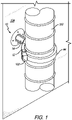
- FIGS. 1-8 show preferred embodiments of the present invention, which is directed to a hose mounting assembly 10 that generally includes a mounting member 12 and a spacer member 14. As shown in FIG. 1 , the mounting assembly 10 is used to secure a hose 100 to a panel 104 using a zip tie or tie member 102
- the mounting member 12 generally includes a base 15 and a main body portion 16 having a semi-circular or arcuate shape.
- the tie tunnel 18 is configured to receive a tie member 102 (e.g., a zip tie, hose clamp, cord, rope, etc.) therethrough.
- the main body portion 16 includes a curved tie tunnel 18 extending therethrough, first and second ends 17 and 19 and a curved mounting surface 32.
- the base 15 includes a first connection opening 21 and the main body portion includes a second connection opening 20 defined therethrough.
- the spacer member 14 generally includes a bonding member or base 22 with a post or extension member 24 extending therefrom.
- the extension member 24 includes first and second opposite ends 24a and 24b.
- the first end 24a includes a mounting guide 25 thereon.
- the mounting member 12 includes guide members or protrusions 27 that mate with the mounting guide 25 on the spacer member 14 to properly align or orient the mounting member 12 and spacer member 14.
- the mounting guide 25 and guide member(s) 27 can be any mating or matching shape and either can be male or female.
- the mounting member 12 and spacer member 14 can be permanently attached or unitary or can be adhered, glued, welded, snap fit, spring fit or otherwise secured together.
- the mounting guide 25 is received in and/or aligned with the second connection opening 20 in the mounting member 12 and is secured therein.
- the mounting guide 25 can be any shape that mates with a complementary shape in the base of the mounting member 12 and helps align the spacer member 14 and the mounting member 12.
- the first end 24a of the extension portion 24 includes at least one and preferably a plurality of recesses 29 defined therein that are part of elongated channels 31 defined longitudinally in the extension member 24 and the base 15 of the mounting member 12 includes at least one and preferably a plurality of complementary protrusions or guide members 27 that are received in the recesses 29.
- the configuration of the mounting guides 25 (recesses 29) and guide members/protrusions 27 allow the mounting member 12 to be rotated in 90 degree increments with respect to the spacer member 14.
- the first end 24a of the extension portion 24 includes a mounting opening 35 defined therein that is coaxial with the first connection opening 21 and the second connection opening 20.
- the mounting opening 35 includes an insert 26 therein that receives a fastener 48 (e.g., a threaded fastener, such as a screw).
- a fastener 48 e.g., a threaded fastener, such as a screw.
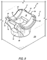
- the fastener 48 can extend first through the spacer member 14 and into the mounting member 12. In an embodiment without the spacer member 14, the fastener 48 connects the mounting member 12 directly to the wall, panel substrate or other object (as shown in FIG. 9 ).
- the base 22 is a disc or other shaped member that includes a surface 28 that is bonded to the surface of a monument, panel or the like.
- the surface 28 includes alignment protrusions 30 extending therefrom that are received in openings in the panel or monument surface.
- the protrusions 30 are formed in a specific pattern so that they can be matched up with the proper openings in the panel. This helps the person installing the assembly 10 to properly orient or align the assembly 10.
- the base 22 of the spacer member 14 also includes installation guide markers 46 (they can be a protrusion, indentation or other mark) on an upper surface 52 thereof. Each installation guide marker 46 is coaxial with an alignment protrusion 30 along an axis that is parallel to the longitudinal central axis of the extension member 24. This provides the installer with a visual guide of where to place the installation guide pins or alignment protrusions 30.
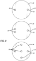
- FIG. 8 shows various alignment protrusion 30 patterns that can be used. These are not a limitation on the present invention.
- the various patterns facilitate manufacturing as substrates/panels will have the proper holes patterns pre-routed therein. It will be appreciated that the base 22 has the same patterned installation guide markers on the top thereof.
- the mounting member 12 and spacer member 14 are made of nylon or other plastic.
- the hose contact or mounting surface 32 has one or more co-molded strips of rubber or mounting guides 42 to provide protection against shaving.
- the fastener 48 is recessed from the mounting surface 32 and tie tunnel 18 so the tie member 102 is clear of interference.
- a hose 100 is placed or received against the mounting guides 42 or mounting surface 32 and a tie member 102 is run or moved through the tie tunnel 18.
- the tie tunnel 18 extends from a first end opening 54 in the first end 17 of the main body portion 16 to a second end opening 56 in the second end.
- a first tie path is defined from the first end opening 54, through the tie tunnel 18 and to and through the second end opening 56.
- the tie member 102 is placed around the hose 100 and the opposite ends 102a and 102b are secured to one another so that the hose 100 is held against the mounting surface 32 (or mounting guides 42).
- first and second tie openings 34 that extend through the mounting surface 32 and are in communication with the tie tunnel 18 can be formed in the main body portion 16.
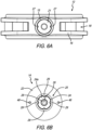
- the tie openings 34 can serve multiple purposes. First, they reduce the weight of the mounting member 12. They also help seat a hose 100 (along with the rectangular central opening) that is secured therein. In another embodiment, as shown in comparing FIGS. 5A and 5B , the tie openings 34 allow the same mounting member 12 to a hose with a smaller diameter.
- the tie member 102 does not run all the way under the mounting surface 32 from end to end of the tie tunnel 18, but instead runs under the mounting surface 32 in the central portion of the main body portion 16 and then extends up through the tie openings 34 and around the hose. Therefore, a second tie path is defined in through the first tie opening 34, through a portion of the tie tunnel 18 and out through the second tie opening 34.
- the purposes of the spacer member 14 is to space the hose from the panel when necessary.
- the spacer member 14 can be omitted and the mounting member 12 can be mounted directly to the panel, as shown in FIG. 9 , which does not show a hose mounting assembly according to the invention.
- a rubber sleeve 44 (or other material) can be placed around the tie member 102 to increase the grip around the hose and prevent the hose from being crushed.
- the sleeve 44 can be omitted.
- different spacer members 14 can be made with different length extension portions 24.
- different sized mounting members 12 can be made for different sized hoses.
- a series of different sized (length) spacer members 14 and a series of different sized mounting members 12 can be sold together as a kit. This will allow the accommodation of different sized hoses and different spacings away from the panel.
Landscapes
- Engineering & Computer Science (AREA)
- General Engineering & Computer Science (AREA)
- Mechanical Engineering (AREA)
- Aviation & Aerospace Engineering (AREA)
- Supports For Pipes And Cables (AREA)
Claims (10)
- Schlauchbefestigungsanordnung (10), umfassend:
ein Befestigungselement (12), das eine Basis (15) und einen Hauptkörperabschnitt (16) einschließt, wobei der Hauptkörperabschnitt ein erstes (17) und ein zweites (19) Ende, einen durch diese hindurch definierten gebogenen Bindetunnel (18) und eine gebogene Befestigungsfläche (32) einschließt, und wobei die Basis eine erste durch diese hindurch definierte Verbindungsöffnung (21) einschließt; und ferner umfassend ein Abstandselement (14), das eine Basis (22) und einen Verlängerungsabschnitt (24) mit einem ersten (24a) und einem zweiten (24b) Ende aufweist, wobei die Basis des Befestigungselements an dem ersten Ende des Verlängerungsabschnitts gesichert ist, wobei die Basis (22) des Abstandselements (14) mindestens einen ersten Ausrichtungsvorsprung (30) einschließt, der sich von einer Bodenfläche davon erstreckt. - Schlauchbefestigungsanordnung nach Anspruch 1, wobei der Hauptkörperabschnitt (16) eine zweite durch diesen hindurch definierte Verbindungsöffnung (20) einschließt, die mit der ersten Verbindungsöffnung (21) koaxial ist, so dass ein Verbindungsweg von der Befestigungsfläche (32) durch den Hauptkörperabschnitt, durch die Basis (15) und durch eine Bodenfläche der Basis definiert ist.
- Schlauchbefestigungsanordnung nach einem der vorhergehenden Ansprüche, wobei die Befestigungsfläche (32) Befestigungsführungen (27) auf dieser einschließt.
- Schlauchbefestigungsanordnung nach einem der vorhergehenden Ansprüche, wobei sich der Bindetunnel (18) von einer ersten Endöffnung (54) in dem ersten Ende (47) zu einer zweiten Endöffnung (56) in dem zweiten Ende (19) erstreckt.
- Schlauchbefestigungsanordnung nach Anspruch 4, wobei der Hauptkörperabschnitt (16) eine darin definierte erste und eine zweite Bindeöffnung (34) einschließt, die den Bindetunnel (18) mit der Befestigungsfläche (32) verbinden, wobei ein erster Bindeweg durch die erste Endöffnung (54), durch den Bindetunnel und nach draußen durch die zweite Endöffnung (56) definiert ist, wobei ein zweiter Bindeweg durch die erste Bindeöffnung, durch einen Abschnitt des Bindetunnels und nach draußen durch die zweite Bindeöffnung definiert ist.
- Schlauchbefestigungsanordnung nach einem der vorhergehenden Ansprüche, wobei das erste Ende (24a) des Verlängerungsabschnitts (24) eine darin definierte Befestigungsöffnung (35) einschließt, die mit der ersten Verbindungsöffnung (21) koaxial ist, und wobei ein Sicherungsmittel in der ersten Verbindungsöffnung und der Befestigungsöffnung aufgenommen ist, um das Befestigungselement (12) an dem Abstandselement (14) zu sichern.
- Schlauchbefestigungsanordnung nach Anspruch 6, wobei das erste Ende (24a) des Verlängerungsabschnitts (24) eines von einem ersten Vorsprung oder einer ersten Ausnehmung (29) einschließt und die Basis (15) des Befestigungselements (12) das andere von dem ersten Vorsprung (27) und der ersten Ausnehmung einschließt und wobei der erste Vorsprung in der ersten Ausnehmung aufgenommen ist.
- Schlauchbefestigungsanordnung nach Anspruch 7, wobei die erste Ausnehmung (29) in dem ersten Ende (24a) des Verlängerungsabschnitts (24) definiert ist, wobei die erste Ausnehmung Teil eines länglichen Kanals (31) ist, der in Längsrichtung in dem Verlängerungsabschnitt definiert ist.
- Schlauchbefestigungsanordnung nach einem der vorhergehenden Ansprüche,
wobei die Basis (22) des Abstandselements (14) mindestens einen ersten Installationsführungsvorsprung (46) auf einer oberen Oberfläche (52) von diesem einschließt, wobei der Verlängerungsabschnitt (24) eine zentrale Längsachse definiert und wobei der erste Installationsführungsvorsprung mit dem ersten Ausrichtungsvorsprung (30) entlang einer Achse koaxial ist, die parallel zu der zentralen Längsachse ist. - Schlauchbefestigungsanordnung nach einem der vorhergehenden Ansprüche, ferner umfassend:
ein Bindeelement (102), das sich durch mindestens einen Abschnitt des Bindetunnels (18) erstreckt, wobei das Bindeelement ein erstes (102a) und ein zweites (102b) Ende aufweist, die außerhalb des Bindetunnels miteinander verbunden sind.
Applications Claiming Priority (3)
| Application Number | Priority Date | Filing Date | Title |
|---|---|---|---|
| US201762465679P | 2017-03-01 | 2017-03-01 | |
| US201762548808P | 2017-08-22 | 2017-08-22 | |
| PCT/US2018/020323 WO2018160764A1 (en) | 2017-03-01 | 2018-02-28 | Hose mounting assembly |
Publications (3)
| Publication Number | Publication Date |
|---|---|
| EP3589873A1 EP3589873A1 (de) | 2020-01-08 |
| EP3589873A4 EP3589873A4 (de) | 2020-11-04 |
| EP3589873B1 true EP3589873B1 (de) | 2023-02-22 |
Family
ID=63355575
Family Applications (1)
| Application Number | Title | Priority Date | Filing Date |
|---|---|---|---|
| EP18761286.6A Active EP3589873B1 (de) | 2017-03-01 | 2018-02-28 | Schlauchbefestigungsanordnung |
Country Status (3)
| Country | Link |
|---|---|
| US (1) | US10473240B2 (de) |
| EP (1) | EP3589873B1 (de) |
| WO (1) | WO2018160764A1 (de) |
Families Citing this family (7)
| Publication number | Priority date | Publication date | Assignee | Title |
|---|---|---|---|---|
| JP6792801B2 (ja) * | 2017-07-04 | 2020-12-02 | 住友電装株式会社 | 細長部材の保持構造 |
| JP7093756B2 (ja) * | 2019-04-11 | 2022-06-30 | 因幡電機産業株式会社 | 長尺体カバー固定具 |
| FR3097932B1 (fr) * | 2019-06-27 | 2023-01-13 | Airbus Operations Sas | Support de conduit comportant au moins deux branches déformables de manière élastique |
| FR3101126B1 (fr) * | 2019-09-24 | 2023-12-15 | Psa Automobiles Sa | Agrafe pour le montage d’un faisceau de câbles électriques de gros diamètres sur un véhicule automobile |
| CN114447846B (zh) * | 2020-11-02 | 2024-02-20 | 台达电子工业股份有限公司 | 开放式线夹、夹线机构及其夹线方法 |
| US12196156B2 (en) * | 2021-07-30 | 2025-01-14 | The Boeing Company | Symmetric cascade thrust reversers and related methods |
| US11677222B1 (en) * | 2021-12-28 | 2023-06-13 | Panduit Corp. | Winged cable mount |
Family Cites Families (10)
| Publication number | Priority date | Publication date | Assignee | Title |
|---|---|---|---|---|
| US2519847A (en) * | 1948-11-13 | 1950-08-22 | Neely Hearne Ellsworth | Pipe coupling |
| US3486725A (en) * | 1968-05-17 | 1969-12-30 | Thomas & Betts Corp | Article lashing support |
| US3632071A (en) * | 1969-11-24 | 1972-01-04 | Panduit Tinley Park | Mount for receiving and retaining a strap |
| DE4305963C2 (de) * | 1993-02-26 | 1995-04-27 | Deutsche Aerospace Airbus | Abstandhalter für Leitungen, insbesondere für elektrische Leitungsbündel in Flugzeugen |
| US6533226B2 (en) * | 2000-09-14 | 2003-03-18 | Hellermanntyton Corporation | Saddle mount |
| US6799607B1 (en) * | 2003-06-18 | 2004-10-05 | Pbm, Inc. | Sanitary conduit support systems and methods |
| US20080078891A1 (en) * | 2006-09-15 | 2008-04-03 | Blake Hobson | Retention Clip Assembly |
| US7861981B2 (en) | 2008-10-22 | 2011-01-04 | Pratt & Whitney Canada Corp. | Protective saddle mount for cable tie |
| CA2829748C (en) * | 2011-03-10 | 2019-09-10 | Bombardier Inc. | Standoff device and method of installation of harness |
| US8894022B2 (en) | 2011-10-19 | 2014-11-25 | Agco Corporation | Variable diameter hose mounting system |
-
2018
- 2018-02-28 US US15/908,651 patent/US10473240B2/en active Active
- 2018-02-28 WO PCT/US2018/020323 patent/WO2018160764A1/en not_active Ceased
- 2018-02-28 EP EP18761286.6A patent/EP3589873B1/de active Active
Also Published As
| Publication number | Publication date |
|---|---|
| EP3589873A4 (de) | 2020-11-04 |
| US20180252336A1 (en) | 2018-09-06 |
| US10473240B2 (en) | 2019-11-12 |
| EP3589873A1 (de) | 2020-01-08 |
| WO2018160764A1 (en) | 2018-09-07 |
Similar Documents
| Publication | Publication Date | Title |
|---|---|---|
| US10473240B2 (en) | Hose mounting assembly | |
| ES2442492T3 (es) | Soporte de montaje ajustable | |
| EP2885838B1 (de) | Klemmvorrichtung zur befestigung einer antenne an einer schiene | |
| US11572913B2 (en) | Or relating to connecting devices | |
| US20220120332A1 (en) | Cable-Clamp System For An Electronic Component Within A Telecommunications Network | |
| US5538208A (en) | Spacer mounting for elongated elements, such as electrical cable bundles | |
| US8608518B2 (en) | Wire-grasping structure for terminal block | |
| US20010011721A1 (en) | Device for fixing a lifeline against a wall | |
| US20150323101A1 (en) | Line clamp assembly and method of use | |
| US11906089B2 (en) | Co-molded snap-on support base, and support system and method of using the same | |
| EP4207521B1 (de) | Flügelkabelhalterung | |
| EP2777991B1 (de) | Multifunktionsadapter | |
| US20190056561A1 (en) | Sliding jaw drop clamp | |
| US11148000B2 (en) | Exercise device | |
| US20120193492A1 (en) | Clamp | |
| JP2007535647A (ja) | 同軸に被覆される燃料管用のスペーサ | |
| EP3222909B1 (de) | Vorrichtung zur montage einer leuchte an einen träger | |
| US12381307B2 (en) | Mounting assembly and method of use thereof | |
| WO2003009516A3 (en) | Cable identification and cable management sliding device | |
| CN204785421U (zh) | 安装手持电子设备的系统 | |
| KR101809734B1 (ko) | 공동주택용 전선지지대 | |
| GB2532943B (en) | Mounting device for plumbing or electrical equipment | |
| KR20160054685A (ko) | 케이블 레이스 웨이용 조인트 | |
| US8782870B2 (en) | Insulator drilling jig | |
| US9379530B2 (en) | Grommet with spreader mounting feature |
Legal Events
| Date | Code | Title | Description |
|---|---|---|---|
| STAA | Information on the status of an ep patent application or granted ep patent |
Free format text: STATUS: THE INTERNATIONAL PUBLICATION HAS BEEN MADE |
|
| PUAI | Public reference made under article 153(3) epc to a published international application that has entered the european phase |
Free format text: ORIGINAL CODE: 0009012 |
|
| STAA | Information on the status of an ep patent application or granted ep patent |
Free format text: STATUS: REQUEST FOR EXAMINATION WAS MADE |
|
| 17P | Request for examination filed |
Effective date: 20191001 |
|
| AK | Designated contracting states |
Kind code of ref document: A1 Designated state(s): AL AT BE BG CH CY CZ DE DK EE ES FI FR GB GR HR HU IE IS IT LI LT LU LV MC MK MT NL NO PL PT RO RS SE SI SK SM TR |
|
| AX | Request for extension of the european patent |
Extension state: BA ME |
|
| DAV | Request for validation of the european patent (deleted) | ||
| DAX | Request for extension of the european patent (deleted) | ||
| A4 | Supplementary search report drawn up and despatched |
Effective date: 20201002 |
|
| RIC1 | Information provided on ipc code assigned before grant |
Ipc: F16L 3/12 20060101ALI20200928BHEP Ipc: B64D 11/00 20060101ALI20200928BHEP Ipc: F16L 3/137 20060101AFI20200928BHEP Ipc: F16L 3/233 20060101ALI20200928BHEP Ipc: F16L 3/123 20060101ALI20200928BHEP Ipc: B65D 63/00 20060101ALI20200928BHEP Ipc: B64C 1/40 20060101ALI20200928BHEP Ipc: F16L 3/08 20060101ALI20200928BHEP |
|
| GRAP | Despatch of communication of intention to grant a patent |
Free format text: ORIGINAL CODE: EPIDOSNIGR1 |
|
| STAA | Information on the status of an ep patent application or granted ep patent |
Free format text: STATUS: GRANT OF PATENT IS INTENDED |
|
| INTG | Intention to grant announced |
Effective date: 20220916 |
|
| GRAS | Grant fee paid |
Free format text: ORIGINAL CODE: EPIDOSNIGR3 |
|
| GRAA | (expected) grant |
Free format text: ORIGINAL CODE: 0009210 |
|
| STAA | Information on the status of an ep patent application or granted ep patent |
Free format text: STATUS: THE PATENT HAS BEEN GRANTED |
|
| AK | Designated contracting states |
Kind code of ref document: B1 Designated state(s): AL AT BE BG CH CY CZ DE DK EE ES FI FR GB GR HR HU IE IS IT LI LT LU LV MC MK MT NL NO PL PT RO RS SE SI SK SM TR |
|
| REG | Reference to a national code |
Ref country code: GB Ref legal event code: FG4D |
|
| REG | Reference to a national code |
Ref country code: CH Ref legal event code: EP |
|
| REG | Reference to a national code |
Ref country code: DE Ref legal event code: R096 Ref document number: 602018046427 Country of ref document: DE |
|
| REG | Reference to a national code |
Ref country code: AT Ref legal event code: REF Ref document number: 1549715 Country of ref document: AT Kind code of ref document: T Effective date: 20230315 Ref country code: IE Ref legal event code: FG4D |
|
| REG | Reference to a national code |
Ref country code: LT Ref legal event code: MG9D |
|
| REG | Reference to a national code |
Ref country code: NL Ref legal event code: MP Effective date: 20230222 |
|
| REG | Reference to a national code |
Ref country code: AT Ref legal event code: MK05 Ref document number: 1549715 Country of ref document: AT Kind code of ref document: T Effective date: 20230222 |
|
| PG25 | Lapsed in a contracting state [announced via postgrant information from national office to epo] |
Ref country code: RS Free format text: LAPSE BECAUSE OF FAILURE TO SUBMIT A TRANSLATION OF THE DESCRIPTION OR TO PAY THE FEE WITHIN THE PRESCRIBED TIME-LIMIT Effective date: 20230222 Ref country code: PT Free format text: LAPSE BECAUSE OF FAILURE TO SUBMIT A TRANSLATION OF THE DESCRIPTION OR TO PAY THE FEE WITHIN THE PRESCRIBED TIME-LIMIT Effective date: 20230622 Ref country code: NO Free format text: LAPSE BECAUSE OF FAILURE TO SUBMIT A TRANSLATION OF THE DESCRIPTION OR TO PAY THE FEE WITHIN THE PRESCRIBED TIME-LIMIT Effective date: 20230522 Ref country code: NL Free format text: LAPSE BECAUSE OF FAILURE TO SUBMIT A TRANSLATION OF THE DESCRIPTION OR TO PAY THE FEE WITHIN THE PRESCRIBED TIME-LIMIT Effective date: 20230222 Ref country code: LV Free format text: LAPSE BECAUSE OF FAILURE TO SUBMIT A TRANSLATION OF THE DESCRIPTION OR TO PAY THE FEE WITHIN THE PRESCRIBED TIME-LIMIT Effective date: 20230222 Ref country code: LT Free format text: LAPSE BECAUSE OF FAILURE TO SUBMIT A TRANSLATION OF THE DESCRIPTION OR TO PAY THE FEE WITHIN THE PRESCRIBED TIME-LIMIT Effective date: 20230222 Ref country code: HR Free format text: LAPSE BECAUSE OF FAILURE TO SUBMIT A TRANSLATION OF THE DESCRIPTION OR TO PAY THE FEE WITHIN THE PRESCRIBED TIME-LIMIT Effective date: 20230222 Ref country code: ES Free format text: LAPSE BECAUSE OF FAILURE TO SUBMIT A TRANSLATION OF THE DESCRIPTION OR TO PAY THE FEE WITHIN THE PRESCRIBED TIME-LIMIT Effective date: 20230222 Ref country code: AT Free format text: LAPSE BECAUSE OF FAILURE TO SUBMIT A TRANSLATION OF THE DESCRIPTION OR TO PAY THE FEE WITHIN THE PRESCRIBED TIME-LIMIT Effective date: 20230222 |
|
| PG25 | Lapsed in a contracting state [announced via postgrant information from national office to epo] |
Ref country code: SE Free format text: LAPSE BECAUSE OF FAILURE TO SUBMIT A TRANSLATION OF THE DESCRIPTION OR TO PAY THE FEE WITHIN THE PRESCRIBED TIME-LIMIT Effective date: 20230222 Ref country code: PL Free format text: LAPSE BECAUSE OF FAILURE TO SUBMIT A TRANSLATION OF THE DESCRIPTION OR TO PAY THE FEE WITHIN THE PRESCRIBED TIME-LIMIT Effective date: 20230222 Ref country code: IS Free format text: LAPSE BECAUSE OF FAILURE TO SUBMIT A TRANSLATION OF THE DESCRIPTION OR TO PAY THE FEE WITHIN THE PRESCRIBED TIME-LIMIT Effective date: 20230622 Ref country code: GR Free format text: LAPSE BECAUSE OF FAILURE TO SUBMIT A TRANSLATION OF THE DESCRIPTION OR TO PAY THE FEE WITHIN THE PRESCRIBED TIME-LIMIT Effective date: 20230523 Ref country code: FI Free format text: LAPSE BECAUSE OF FAILURE TO SUBMIT A TRANSLATION OF THE DESCRIPTION OR TO PAY THE FEE WITHIN THE PRESCRIBED TIME-LIMIT Effective date: 20230222 |
|
| REG | Reference to a national code |
Ref country code: CH Ref legal event code: PL |
|
| REG | Reference to a national code |
Ref country code: BE Ref legal event code: MM Effective date: 20230228 |
|
| PG25 | Lapsed in a contracting state [announced via postgrant information from national office to epo] |
Ref country code: SM Free format text: LAPSE BECAUSE OF FAILURE TO SUBMIT A TRANSLATION OF THE DESCRIPTION OR TO PAY THE FEE WITHIN THE PRESCRIBED TIME-LIMIT Effective date: 20230222 Ref country code: RO Free format text: LAPSE BECAUSE OF FAILURE TO SUBMIT A TRANSLATION OF THE DESCRIPTION OR TO PAY THE FEE WITHIN THE PRESCRIBED TIME-LIMIT Effective date: 20230222 Ref country code: LU Free format text: LAPSE BECAUSE OF NON-PAYMENT OF DUE FEES Effective date: 20230228 Ref country code: LI Free format text: LAPSE BECAUSE OF NON-PAYMENT OF DUE FEES Effective date: 20230228 Ref country code: EE Free format text: LAPSE BECAUSE OF FAILURE TO SUBMIT A TRANSLATION OF THE DESCRIPTION OR TO PAY THE FEE WITHIN THE PRESCRIBED TIME-LIMIT Effective date: 20230222 Ref country code: DK Free format text: LAPSE BECAUSE OF FAILURE TO SUBMIT A TRANSLATION OF THE DESCRIPTION OR TO PAY THE FEE WITHIN THE PRESCRIBED TIME-LIMIT Effective date: 20230222 Ref country code: CZ Free format text: LAPSE BECAUSE OF FAILURE TO SUBMIT A TRANSLATION OF THE DESCRIPTION OR TO PAY THE FEE WITHIN THE PRESCRIBED TIME-LIMIT Effective date: 20230222 Ref country code: CH Free format text: LAPSE BECAUSE OF NON-PAYMENT OF DUE FEES Effective date: 20230228 |
|
| REG | Reference to a national code |
Ref country code: DE Ref legal event code: R097 Ref document number: 602018046427 Country of ref document: DE |
|
| PG25 | Lapsed in a contracting state [announced via postgrant information from national office to epo] |
Ref country code: SK Free format text: LAPSE BECAUSE OF FAILURE TO SUBMIT A TRANSLATION OF THE DESCRIPTION OR TO PAY THE FEE WITHIN THE PRESCRIBED TIME-LIMIT Effective date: 20230222 |
|
| REG | Reference to a national code |
Ref country code: IE Ref legal event code: MM4A |
|
| PLBE | No opposition filed within time limit |
Free format text: ORIGINAL CODE: 0009261 |
|
| STAA | Information on the status of an ep patent application or granted ep patent |
Free format text: STATUS: NO OPPOSITION FILED WITHIN TIME LIMIT |
|
| PG25 | Lapsed in a contracting state [announced via postgrant information from national office to epo] |
Ref country code: MC Free format text: LAPSE BECAUSE OF FAILURE TO SUBMIT A TRANSLATION OF THE DESCRIPTION OR TO PAY THE FEE WITHIN THE PRESCRIBED TIME-LIMIT Effective date: 20230222 |
|
| 26N | No opposition filed |
Effective date: 20231123 |
|
| PG25 | Lapsed in a contracting state [announced via postgrant information from national office to epo] |
Ref country code: SI Free format text: LAPSE BECAUSE OF FAILURE TO SUBMIT A TRANSLATION OF THE DESCRIPTION OR TO PAY THE FEE WITHIN THE PRESCRIBED TIME-LIMIT Effective date: 20230222 Ref country code: MC Free format text: LAPSE BECAUSE OF FAILURE TO SUBMIT A TRANSLATION OF THE DESCRIPTION OR TO PAY THE FEE WITHIN THE PRESCRIBED TIME-LIMIT Effective date: 20230222 Ref country code: IE Free format text: LAPSE BECAUSE OF NON-PAYMENT OF DUE FEES Effective date: 20230228 |
|
| PG25 | Lapsed in a contracting state [announced via postgrant information from national office to epo] |
Ref country code: BE Free format text: LAPSE BECAUSE OF NON-PAYMENT OF DUE FEES Effective date: 20230228 |
|
| PG25 | Lapsed in a contracting state [announced via postgrant information from national office to epo] |
Ref country code: IT Free format text: LAPSE BECAUSE OF FAILURE TO SUBMIT A TRANSLATION OF THE DESCRIPTION OR TO PAY THE FEE WITHIN THE PRESCRIBED TIME-LIMIT Effective date: 20230222 |
|
| PG25 | Lapsed in a contracting state [announced via postgrant information from national office to epo] |
Ref country code: BG Free format text: LAPSE BECAUSE OF FAILURE TO SUBMIT A TRANSLATION OF THE DESCRIPTION OR TO PAY THE FEE WITHIN THE PRESCRIBED TIME-LIMIT Effective date: 20230222 |
|
| PG25 | Lapsed in a contracting state [announced via postgrant information from national office to epo] |
Ref country code: BG Free format text: LAPSE BECAUSE OF FAILURE TO SUBMIT A TRANSLATION OF THE DESCRIPTION OR TO PAY THE FEE WITHIN THE PRESCRIBED TIME-LIMIT Effective date: 20230222 |
|
| PG25 | Lapsed in a contracting state [announced via postgrant information from national office to epo] |
Ref country code: CY Free format text: LAPSE BECAUSE OF FAILURE TO SUBMIT A TRANSLATION OF THE DESCRIPTION OR TO PAY THE FEE WITHIN THE PRESCRIBED TIME-LIMIT; INVALID AB INITIO Effective date: 20180228 |
|
| PG25 | Lapsed in a contracting state [announced via postgrant information from national office to epo] |
Ref country code: HU Free format text: LAPSE BECAUSE OF FAILURE TO SUBMIT A TRANSLATION OF THE DESCRIPTION OR TO PAY THE FEE WITHIN THE PRESCRIBED TIME-LIMIT; INVALID AB INITIO Effective date: 20180228 |
|
| PG25 | Lapsed in a contracting state [announced via postgrant information from national office to epo] |
Ref country code: TR Free format text: LAPSE BECAUSE OF FAILURE TO SUBMIT A TRANSLATION OF THE DESCRIPTION OR TO PAY THE FEE WITHIN THE PRESCRIBED TIME-LIMIT Effective date: 20230222 |
|
| PGFP | Annual fee paid to national office [announced via postgrant information from national office to epo] |
Ref country code: GB Payment date: 20260219 Year of fee payment: 9 |
|
| PGFP | Annual fee paid to national office [announced via postgrant information from national office to epo] |
Ref country code: DE Payment date: 20260217 Year of fee payment: 9 |
|
| PGFP | Annual fee paid to national office [announced via postgrant information from national office to epo] |
Ref country code: FR Payment date: 20260219 Year of fee payment: 9 |