EP3589814B1 - Teleskopisch ausziehbare und zusammenklappbare leiter mit luftdämpfern - Google Patents
Teleskopisch ausziehbare und zusammenklappbare leiter mit luftdämpfern Download PDFInfo
- Publication number
- EP3589814B1 EP3589814B1 EP18710563.0A EP18710563A EP3589814B1 EP 3589814 B1 EP3589814 B1 EP 3589814B1 EP 18710563 A EP18710563 A EP 18710563A EP 3589814 B1 EP3589814 B1 EP 3589814B1
- Authority
- EP
- European Patent Office
- Prior art keywords
- air
- ladder
- air chamber
- stile
- ladder section
- Prior art date
- Legal status (The legal status is an assumption and is not a legal conclusion. Google has not performed a legal analysis and makes no representation as to the accuracy of the status listed.)
- Active
Links
Images


Classifications
-
- E—FIXED CONSTRUCTIONS
- E06—DOORS, WINDOWS, SHUTTERS, OR ROLLER BLINDS IN GENERAL; LADDERS
- E06C—LADDERS
- E06C1/00—Ladders in general
- E06C1/02—Ladders in general with rigid longitudinal member or members
- E06C1/04—Ladders for resting against objects, e.g. walls poles, trees
- E06C1/08—Ladders for resting against objects, e.g. walls poles, trees multi-part
- E06C1/12—Ladders for resting against objects, e.g. walls poles, trees multi-part extensible, e.g. telescopic
- E06C1/125—Ladders for resting against objects, e.g. walls poles, trees multi-part extensible, e.g. telescopic with tubular longitudinal members nested within each other
-
- E—FIXED CONSTRUCTIONS
- E06—DOORS, WINDOWS, SHUTTERS, OR ROLLER BLINDS IN GENERAL; LADDERS
- E06C—LADDERS
- E06C7/00—Component parts, supporting parts, or accessories
- E06C7/02—Extending means
Definitions
- the present invention relates to a telescopically extendable and collapsible ladder assembly having a bottom ladder section, a top ladder section, and one or more intermediate ladder sections.
- the invention relates to a ladder assembly provided with air dampers that provide retardation of a gravity induced velocity of the collapsible ladder sections during collapse of the ladder assembly.
- a telescopically extendable and collapsible ladder assembly typically comprises multiple ladder sections with two tubular stile members, each tubular stile member having a bottom end and a top end and each tubular stile member defining an inner space therein, which tubular stile members are arranged parallel to each other and are interconnected at the top end by a ladder rung to form an essentially U-shaped ladder section.
- the tubular stile members of the bottom ladder section are furthermore connected by a bottom ladder rung.
- the top ladder section and the one or more intermediate ladder sections are collapsible ladder sections, each collapsible ladder section having the bottom ends of the tubular stile members telescopically inserted into the top ends of the tubular stile members of an adjacent ladder section, the adjacent ladder section being the bottom ladder section or an intermediate ladder section, such that each collapsible ladder section is movable relative to the adjacent ladder section between a collapsed position and an extended position.
- the ladder assembly comprises latch mechanisms adapted to lock the telescopically inserted tubular stile members of the collapsible ladder section relative to the adjacent ladder section when the collapsible ladder section is in the extended position, the latch mechanisms being associated with actuators for unlocking the tubular stile members in order to allow for collapsing of the ladder assembly, i.e. moving al collapsible ladder sections into the collapsed position.
- ladder assemblies have become quite popular as portable ladders, such as a straight telescopic ladder, a stepladder, or another "ladder product” such as a combination ladder, a work platform with ladder like telescopic legs, etc..
- each of these air dampers at the bottom end of a stile member of a collapsible section is embodied as a body that establishes a peripheral air seal with the interior of the stile member of the adjacent ladder section. So, upon collapse of the collapsible ladder section, a volume of air is trapped between the outer stile member of the adjacent ladder section and the collapsing inner stile member with the air damper functioning like a piston within a cylinder. The design is based on the escape of trapped and pressurized air from this entrapped volume via the orifice in the air damper, thereby retarding the motion of the collapsing ladder section.
- the same sealing ring Upon extension of the ladder section, the same sealing ring is moved into a position at the axially lower end of the groove, thereby clearing larger air inlet openings so that air can be easily replenished into this volume. So the extension of the ladder is not hampered by the air damper.
- GB 2 536 297 A discloses a telescopically extendable and collapsible ladder assembly according to the preamble of independent claim 1.
- the provision of air dampers in telescopic ladder assemblies is commonly seen as an alternative for designs wherein the ladder assembly is embodied to provide a finger pinching prevention spacing, e.g. of at least 25 mm, between the rungs in the collapsed condition of the ladder assembly.
- the connectors that connect the rungs at their ends to the top ends of the stile members may be each provided with an upwardly extending finger pinching spacer member that keeps one rung at a finger pinching safe distance from the other rung, for example as disclosed in WO2016028147 .
- the provision of finger pinching prevention spacing may also be contemplated within the scope of the present invention.
- the present invention aims to provide an improved air damper design, or at least an alternative for existing air damper designs.
- the invention provides a telescopically extendable and collapsible ladder assembly according to claim 1.
- each of the air dampers comprises an axially compressible and expandable air chamber member having an internal air chamber, said air chamber member being provided with means providing an air flow restricting passage for air pressurized in said internal air chamber and forced out of said internal air chamber upon mechanical compression of the air chamber member from an expanded state into a compressed state as the collapsing ladder section reaches its collapsed position, which air chamber member is adapted to expand upon later extension of said collapsing ladder section.
- the pressurized air is present within the internal air chamber formed by the air chamber member itself and not, as in the mentioned prior art examples, in a space that is delimited by the stile member of the adjacent ladder section on the one hand and the stile member of the descending collapsible ladder section on the other hand.
- An advantage thereof is, for example, that there is no longer a requirement for an air seal between the telescoping stile members. Air may simple be allowed to be exhausted from the space mentioned above during collapse of the ladder without hindrance, and therefor air may also be sucked back in via the same route upon extending the ladder. As no air seal between telescoping ladder sections is required, frictional forces that could hamper the extension of the ladder may also be avoided.
- the range of operation of the air damper i.e. when the air dampers start to retard the collapsing motion of the collapsing ladder section, is governed by the structural design of the air chamber member of the air damper as the compression thereof takes place upon mechanical interaction.
- the air chamber member can be readily designed to undergo a predetermined axial compression when the collapsible ladder section moves into its collapsed position. This translates into a predetermined reduction of the volume of the air chamber and thus pressurization. In combination with a suitable selection of the air flow restricting passage for the pressurized air being forced out of the internal air chamber this will provide a desired retardation of the ladder section during the time span that the air chamber member is compressed.
- the air dampers guarantee that upon collapse there is a 25 mm spacing between the descending ladder rung and the one below during at least 1.5 seconds counted from the start of the descending motion.
- each collapsible ladder section is provided with an bottom fitting at the bottom end of each respective stile member, with the air chamber member being secured to a bottom fitting.
- the air chamber member upon collapsing of a collapsible ladder section, becomes compressed between the bottom fitting of the adjacent stile member and the bottom fitting of the collapsing stile member.
- each bottom fitting is a plastic bottom fitting, e.g. with one or more bosses snap fitted into corresponding holes in the lower end portion of a stile member.
- each bottom fitting is provided with one or more apertures that allow air to pass through the bottom fitting, e.g. to have in permanent open communication
- the air damper is provided with an air inlet valve that opens upon expansion of the air chamber member from its compressed state to its expanded state and that closes or is closed upon compression of the air chamber member from its expanded state to its compressed state.
- an air inlet valve that opens upon expansion of the air chamber member from its compressed state to its expanded state and that closes or is closed upon compression of the air chamber member from its expanded state to its compressed state.
- the air inlet valve comprises a movable valve member and a stationary seat, wherein the movable valve member is remote from said seat in opened condition of the air inlet valve and resting on said seat in closed condition of the air inlet valve, and wherein said air flow restricting passage is integrated in the movable valve member and/or in the seat, so - with said air inlet valve in closed condition - air pressurized in said internal air chamber upon mechanical compression of the air chamber member will pass through said flow restriction passage.
- the movable valve member is a movable valve disc having a circumference adapted to sealingly engage on the seat in closed condition of the air inlet valve, wherein the movable valve disc is provided with one or more air flow restricting holes therein.
- the air chamber member has a synthetic material flexible wall delimiting said internal air chamber, e.g. embodied as a bellows, said wall having a port, preferably solely a single port, connected to or forming said means providing an air flow restricting passage.
- the air chamber is embodied as a piston and cylinder device that is axially compressible and expandable, with the rigid piston part being reciprocable within the rigid cylinder part and with an air seal in between. It will be appreciated that such a device entails sliding relative motion as well as a sliding air seal, and it is expected that this will less attractive than a bellows for reliability and cost price reasons.
- the axially compressible air chamber member is a bellows having a corrugated tubular body forming said internal air chamber and having an axial extension parallel to the stile member and first and second axial ends, wherein a connector portion is provided at said first axial end, which connector portion is connected to a bottom end of a tubular stile member, e.g. to a bottom fitting, and wherein the second axial end of the bellows is closed.
- an air duct is provided at the first axial end of the bellows, which air duct extends between the internal air chamber in the bellows and a space within a stile member, wherein said air duct is preferably at least provided with said means providing an air flow restricting passage.
- an air duct is provided at the first axial end of the bellows, which air duct extends between the internal air chamber in the bellows and a space within a stile member, wherein said air duct is both provided with said means providing an air flow restricting passage and air inlet valve.
- an air duct is provided at the first axial end of the bellows, which air duct extends between the internal air chamber in the bellows and a space within a stile member, wherein said air duct is provided with an air inlet valve that opens upon expansion of the air chamber member from its compressed state to its expanded state and that closes or is closed upon compression of the air chamber member from its expanded state to its compressed state, wherein the air inlet valve comprises a movable valve member and a stationary seat, wherein the movable valve member is remote from said seat in opened condition of the air inlet valve and resting on said seat in closed condition of the air inlet valve, and wherein said air flow restricting passage is integrated in the movable valve member and/or in the seat, so - with said air inlet valve in closed condition - air pressurized in said internal air chamber upon mechanical compression of the air chamber member will pass through said flow restriction passage.
- the air damper is mounted to the bottom end of the stile member and extends downward beyond the stile member. It is however, see figure 12 , also envisaged that an air chamber member is fitted on top of a bottom fitting of a stile member, so effectively within the contour of the lower end portion of a stile member, in order to retard the descent of a higher or more inward collapsible ladder section.
- the axially compressible and expandable air chamber member is adapted to resiliently expand from the compressed state into the expanded state upon said later extension of said collapsing ladder section.
- the air chamber member comprises a resilient synthetic material flexible wall delimiting said internal air chamber.
- the spring could be arranged within the bellows, so the bellows shielding the spring from the outside, or arranged outside of the bellows, e.g. within a helical contour when combined with a helical bellows design.
- the ladder is provided with interacting engagement means on the expandable air chamber member arranged on one stile member and on the other stile member respectively, these interacting engagement means being adapted to bias the air chamber into the expanded state thereof.
- a flexible or telescopic tensile member e.g. a string
- Another alternative could be the provision of a snap or friction fit arrangement that - upon extension of the collapsing ladder section - in an initial phase of said extension, by said snap or friction fit of interacting portions of the air chamber member arranged on one stile member on the one hand and the other stile member on the other hand retains the air chamber member connected to the bottom end of one stile member to the bottom end of the other stile member so as to bias the air chamber member into the expanded state thereof, and which disconnects upon further extension of the collapsing ladder section.
- ballast weight e.g. of metal, e.g. metal interacting with said one or more magnets, the weight biasing said air chamber member into its expanded state.
- the stile members of the top ladder sections are provided with one or more vent holes allowing air to move in and out of the stile members.
- the present inventions also relates to the use of the ladder described herein, for example the collapsing thereof.
- the present invention also relates to a method for collapsing of a collapsible ladder section in a ladder as described herein, wherein the air dampers provide retardation of gravity induced velocity of the collapsible ladder section upon collapse thereof as the air chamber member becomes mechanically compressed between the collapsing ladder section and the bottom of the adjacent ladder section as the collapsing ladder section reaches its collapsed position, so that air within the internal air chamber of said air chamber member is pressurized and escapes via the means providing an air flow restricting passage for the air.
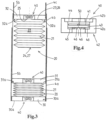
- Figures 1 and 2 show an example of a telescopically extendable and collapsible ladder assembly according to the invention, here embodied as a straight telescopic ladder 1.
- the ladder assembly may also be part of another "ladder product" such as a stepladder or combination ladder, a work platform with ladder like telescopic legs, etc.
- the ladder assembly 1 has a bottom ladder section 2, a top ladder section 3, and multiple intermediate ladder sections 4a - e, in the particular embodiment shown five.
- Each of the ladder sections 2, 3, 4a - e comprises two tubular stile members 5, 6, each having a bottom end 5a, 6a and a top end 5b, 6b and each tubular stile member defining an inner space therein.
- the tubular stile members 5, 6 are arranged parallel to each other and are interconnected at the top end by a ladder rung 7 to form a U-shaped ladder section.
- the tubular stile members of the bottom ladder section 2 are furthermore connected by a bottom ladder rung 8.
- the top ladder section 3 and the intermediate ladder sections 4a - e are collapsible ladder sections of the ladder 1.
- the bottom ends 5a, 6a of the tubular style members 5, 6 have been telescopically inserted into the top end 5b, 6b of the tubular stile members 5, 6 of an adjacent ladder section to allow the collapsible ladder section to be moved relative to the adjacent ladder section between a collapsed position ( fig. 1 ) and an extended position ( fig. 2 ), and thus enable collapse and extension of the telescopic ladder.
- the collapsible ladder sections are each provided with a pair of air dampers 20, here at the bottom end 5a,6a of each tubular stile members 5,6. It is noted that figure 2 shows the location of the air dampers 20 when the ladder is extended.
- the air dampers 20 provide retardation of gravity induced velocity of the collapsible ladder sections 3, 4a - e, upon collapse of the ladder sections, which may take place starting from ladder section 4a, then ladder section 4b, etc. until finally the top ladder section 3 is collapsed. This may be done by automatic latching mechanisms as is known in the art, e.g. based on manual operation of one or more actuators on the bottom ladder section 2.
- Each stile member 5, 6 of the bottom ladder section 2 in the exemplary embodiment shown is provided with a ground engaging foot member 11 (e.g. of rubber or the like).
- the exemplary ladder assembly 1 further illustrates the provision of automatic latch mechanisms for locking the telescopically inserted tubular stile members of the collapsible ladder sections relative to the adjacent ladder sections when the collapsible ladder section are in the extended position, the latch mechanisms being associated with actuators for unlocking the tubular stile members in order to allow for collapsing of the ladder assembly.
- actuators 10 may be embodied as disclosed in WO2016028147 .
- one or more manually operated actuators 10a are arranged on a rung, e.g. on the bottom side thereof, of the bottom ladder section 2.
- a pair of actuators as arranged so as to be operable simultaneously with a single hand.
- the ladder further comprises automatically operated actuators 10b, e.g. as described in WO2016028147 .
- the actuators 10b are provided in the form of upward fingers located at the top of the rung and each extending alongside a respective the stile members.
- the fingers provided on top of the ladder rung of the lower or adjacent ladder section each engage a latch mechanism provided in the rung of the collapsing ladder section, by which action the fingers unlock the stile members of that ladder section, such that the ladder sections collapses and the process is repeated for the next collapsible ladder section.
- the collapsible ladder sections collapse one after the other.
- Other automatic mechanisms are known in the art and may be integrated in the present invention as well.
- the upward fingers might be extended so as to provide for an anti finger-pinching spacing between the rungs in the collapsed condition of the ladder or some other anti-pinching spacing mechanism may be provided.
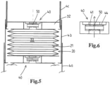
- each of the intermediate ladder sections 4a - e as well as the top ladder section 3 is provided with a pair of air dampers 20, one for each stile member of the respective ladder section.
- the axially compressible and expandable air chamber member is a bellows 21 having a corrugated tubular body forming the internal air chamber 22.
- the corrugations can be of any suitable design, e.g. folded as shown here with folds at peaks and valleys, or meandering with curved transitions at the peaks and valleys.
- the corrugations can extend circumferentially only, or in another embodiment in a helix relative to the length of the tubular body.
- the corrugated tubular body of bellows 21 can have a substantially uniform cross-section over its length, that is with all corrugations being substantially the same in diameter as shown here.
- the tubular body of bellows 21 can be tapered having a diameter at one axial end thereof that differs, e.g. by at least 25%, from the diameter at the other axial end thereof.
- the bellows 21, in compressed state has a diameter that is between 0.6 and 0.95 times the internal diameter of the surrounding stile member, e.g. between 0.75 and 0.95 times the internal diameter of the surrounding stile member.
- the bellows 21 has a gastight flexible wall that is made of a synthetic material, e.g. plastic, e.g. polyurethane, with this flexible wall delimiting the internal air chamber 22.
- a synthetic material e.g. plastic, e.g. polyurethane
- the tubular body of the bellows 21 has an axial extension parallel to the stile members and has first and second axial ends, 23, 24 respectively.
- a connector portion 25 is provided at the first axial end 23, e.g. the portion being a flange or ferrule.
- the first axial end 23 of the bellows 21 is provided with a transverse wall portion 26 of the bellows 21 that is integral with the corrugated peripheral wall portion of the bellows.
- the wall portion has a central opening therein, e.g. leading into a ferrule that is secured in an inlet valve.
- the stile members are hollow extrusion profiles of aluminium, e.g. having a circular cross-section, a circular cross-section that has a flat section as in WO20160218147 , or another cross-section, e.g. oval, triangular with rounded transitions, etc.
- each ladder section 4a, 4b, 4c is provided with a bottom fitting 30, 31, 32, e.g. injection molded of rigid plastic material, e.g. secured by one or more bosses molded onto the fitting 30, 31, 32 and locking into corresponding openings in the wall of the stile member 5.
- Each bottom fitting 30, 31, 32 is provided with apertures 30a,31a,32a, so that air can air can easily move within the interior space formed by the telescoping stile members.
- the bellows 21 is secured at the first axial end 23 to the bottom fitting 30, 31, 32 so as to extend generally downward below the stile member to which the bellows 21 is secured.
- the bellows 21 is closed at the opposed second axial end 24, here by a transverse wall portion 27 that is integral with the corrugated peripheral wall portion of the bellows 21.
- a transverse wall portion 27 that is integral with the corrugated peripheral wall portion of the bellows 21.
- both the transverse wall portion 26 and the corrugated peripheral wall portion of the bellows 21 are monolithically made from suitable plastic material.
- the air damper 20 is provided with an air inlet valve 40 that opens upon expansion of the bellows 21 from its compressed state to its expanded state and that closes or is closed upon compression of the bellows 21 from its expanded state to its compressed state.
- the air inlet valve 40 here comprises a movable valve member, that is here embodied as a movable valve disc 41 provided with one or more air flow restricting holes therein, here a single air flow restricting hole 50.
- the valve 40 further has a valve housing 42 mounted to the bottom fitting 30, 31, 32 and to the transverse wall portion 26 that is integral with the corrugated peripheral wall portion of the bellows 21.
- the valve housing 42 here comprises two housing parts 42a, b through which the air duct extends, and wherein an enlarged diameter bore portion 43 received the valve disc 41.
- the valve housing 42 forms at opposed axial ends of said enlarged diameter bore portion 43 a first valve seat 44 and a second valve seat 45 for the valve disc.
- the first valve seat 44 is embodied such that, if the valve disc 41 mates with said valve seat 44, the air inlet valve 40 is closed, here as the outer circumference of the disc 45 sealing engages the valve seat 44. As will be appreciated, in this closed condition of the inlet valve 40, air can pass through the flow restricting hole 50.
- the valve disc has a smaller diameter or the like as the receiving bore portion 43 and the second valve seat 45 is embodied such that, if the valve disc 41 mates with said valve seat 45, air inlet passages are still open, e.g. with the seat 45 having radial grooves 46 therein as depicted here so that air can pass around the outer circumference of the disc 41 and via said grooves into the bellows 21 with significantly less flow resistance than via just the hole 50.
- Figures 3 and 4 illustrate the disc 41 in a floating position as at this stage the position of the disc 41 is of no relevance for the operation of the air damper 20.
- This axial compression cause the air in air chamber 22 to be pressurized, which in turn presses the valve disc 41 onto the seat 44 so as to bring the air inlet valve 40 in its closed condition.
- This is depicted in figure 6 and means that, as the wall of the bellows 21 is gastight, that the trapped pressurized air can now only escape via the hole 50 in the disc 41.
- This air flow restriction which could also be named flow orifice, throttling orifice, and the like, is such that the motion of the collapsing ladder section, and any ladder sections that follow said collapsing motion, is retarded.
- the collapsed position of the ladder section is preferably, as here and as is common, determined by mechanical abutment of portions of the ladder sections distinct from the air dampers, for example of connectors that connect the rungs at their ends to the stile members.
- the air dampers will most practically be employed in ladder assemblies where there is no finger spacing maintained between rungs of the collapsed ladder assembly.
- Figures 7, 8 illustrate the functionality upon later extension of the previously collapsed ladder section 4c.
- the bellows 21 can expand towards its original expanded state.
- the bellows 21 itself, so the wall thereof, is resilient, and this resiliency causes said return of the bellows to the expanded state.
- Figures 9, 10 illustrate the provision, e.g. as an alternative to self-expansion of the bellows 21 or to be combined therewith, of a flexible tensile member, here one or more strings 60, 61 that are at one end connected to the bottom 27 of the bellows 21 and at the other end to the bottom fitting 30.
- the length of these one or more strings is such that- upon extension of the collapsing ladder section - in a final phase of said extension the string biases, e.g. stretches, the bellows 21, into the expanded state thereof.
- the one or more strings 60, 61 simply fall down without unduly interfering with the retarding operation provided by the bellows.
- the one or more strings are elastic strings.
- some telescoping tensile member can be envisaged.
- Figure 11 illustrates the provision of a magnet arrangement with one or more permanent magnets 70, 71 that - upon extension of the collapsing ladder section 4c - in an initial phase of said extension, magnetically retains the bellows 21 or other air chamber member.
- a metal component 72 is connected to the second axial end of air chamber member, e.g. a metal ring. This magnetic retention will keep the bottom of the bellows 21 secured to the underlying bottom fitting 30 until the bellows 21 has been stretched out and a force is exerted that overcomes the magnetic retention force. Then the bottom of the bellows 21 is released.
- Figure 12 illustrates, as will be readily understood, that one can also envisage that the bellows 21 or other embodiment of the air chamber member is connected to extend upwards from a bottom fitting 30, 31, and into the respective stile member onto which said bottom fitting is secured.
- the air inlet valves 40 are arranged accordingly.
- the air chamber member 21 can have another design, e.g. like a balloon with a synthetic material flexible wall delimiting the internal air chamber. As shown for the bellows 21, and as may apply to other designs, it is preferred for said wall to solely have a single port therein, connected to or forming the means providing an air flow restricting passage.
- the diameter of the ladder stiles is different for each ladder section. Nonetheless it is envisaged, in an embodiment, that the bellows 21 all may be the same or at least in less versions than there are ladder sections.
- the means providing the flow resisting passage are exchangeable parts of the ladder, e.g. so that for a ladder valve discs 41 having different holes 50 are provided to create the desired flow resistance for each ladder section.
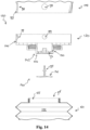
- Figure 13 shows in cross section a partial view of an air damper 120 that is mounted on a bottom end of a stile member 105. More in particular, the air damper 120 has an air chamber member 121 that is mounted on a bottom fitting 130 that in turn is mounted on the bottom end of the stile member 105.
- Figure 14 depicts an exploded view of the air damper 120 of Figure 13 .
- the bottom fitting 130 is injection molded of a rigid plastic material.
- the bottom fitting 130 comprises an annular wall 100, that defines a space receiving the bottom end of the stile member 105.
- the annular wall 100 is provided with inward projecting bosses 99, molded onto the bottom fitting 130, that are configured to lock into corresponding openings 98 in a wall 97 of the stile member 105.
- the axially compressible and expandable air chamber member is a bellows 121 having a corrugated tubular body forming the internal air chamber 122.
- the air chamber member can have another design, e.g. like a balloon with a synthetic material flexible wall delimiting the internal air chamber.
- the wall delimiting the internal air chamber it is preferred for the wall delimiting the internal air chamber to solely have a single port 96 therein, connected to or forming the means providing an air flow restricting passage.
- the bellows 121 is secured at its first axial end 123 to the bottom fitting 130 so as to extend generally downward below the stile member 105 to which the air damper 120 is secured.
- the bellows 121 is closed at the opposed second axial end, which is not shown in the figures.
- the expandable air chamber member is a monolithical body made from suitable plastic material, for example by way of the blow moulding process or an alternative suitable manufacturing process.
- a connector portion 125 is provided at the first axial end 123 of the air chamber member 121.
- the connector portion 125 is embodied as a neck part, which neck part 125 has as a central opening the opening 96 that enables air to flow into and out off the internal air chamber 122 of the air chamber member 121.
- the neck part 125 is provided with external screw thread, for connecting the air chamber member 121 to corresponding screw thread of the bottom fitting 130.
- the connector portion is integral with the corrugated peripheral wall portion of the bellows.
- the connector portion is a separate component, for example formed by injection moulding, that is connected to the bellows, which bellows may be obtained by for example a blow moulding process.
- the connector portion is provided as a connector type component, that is to be secured to the bottom fitting, for example by way of screw thread or utilising click fingers, and that is configured to clamp the air chamber member, or a tubular end part thereof, to the bottom fitting, preferably clamping part of the air chamber member between the connector and the bottom fitting.
- the air damper 120 is provided with an air inlet valve 140 that opens upon expansion of the bellows 121 from its compressed state to its expanded state and that closes or is closed upon compression of the bellows 121 from its expanded state to its compressed state.
- the valve 140 has a valve housing 142, which valve housing in the embodiment shown is integral with the bottom fitting 130.
- the valve housing 142 comprises a bowl shaped seat 144 for receiving a valve disc 141.
- the bowl shaped valve seat 144 is provided with apertures 94 that allow for air to flow into the bellows, when the air inlet valve is open.
- the air inlet valve 140 further comprises a movable valve member, that is here embodied as a movable valve disc 141 having a central anchoring stem 95.
- the anchoring stem 95 is configured to secure the valve disc 141 to the valve housing 142.
- valve seat 144 and the valve disc 141 are embodied such that, if the valve disc 141 mates with said valve seat 144, the air inlet valve 140 is closed, here as the outer circumference of the valve disc 141 sealing engages the valve seat 144.
- the moveable valve disc 141 is a flexible disc, which flexibility allows for the valve disc to resiliently move between a state in which it is received in the valve seat, and thus prevents air from flowing through the apertures 94 provided in the valve seat, and a state in which it allows for air to flow between the disc and through the apertures 94 provided in the valve seat.
- the valve disc is configured such that a pressure difference between the air chamber 122 of the air chamber member 121 and the inner space of the stile member 105 moves the valve disc between the open and the closed state.
- the air inlet valve When the bellows is compressed, the pressure inside the bellow is raised and the valve disc is pressed into the valve seat. Thus, the air inlet valve is closed.
- air can escape the internal air chamber 122 of the air chamber member 121 only via an air flow restricting passage in the form of hole 150 provided in the valve seat, adjacent the area sealed by the valve disc.
- the air flow restricting passage allows for air to escape the air chamber of the air chamber member when the air inlet valve is closed.
- the flow restriction passage therefore is not sealed by the moveable valve member of the air inlet valve, when the air inlet valve is closed.
- Closing the air inlet valve restricts the air flow out of the air chamber, which slows down compression of the bellows and thus slows down the stile member being inserted into a stile member of an adjacent ladder section.
- one or more alternative flow restriction holes can be provided to enable air to escape the internal air chamber 122 of the air chamber member 121 when the air inlet valve is closed.
- the valve seat can be configured to allow air to pass through the apertures in the bowl shaped seat by not providing an air tight seal between the valve disc and the valve seat.
- the edge of the bowl shaped valve seat can have a corrugated shape providing radial grooves in the seat surface.
- Figure 13 illustrates the air inlet valve 140 in its closed condition.
- This air flow restriction 150 which could also be named flow orifice, throttling orifice, and the like, is such that the motion of the collapsing ladder section is retarded.
- the exemplary embodiment of the air damper 120 shown in figures 13 and 14 is an alternative to the exemplary embodiment shown in figure 4 , in which the air flow restriction opening 50 is provided in the valve disc 41.
- both valve seat and the valve disc are provided with one or more air flow restriction openings enabling air to escape from the air chamber when the air inlet valve is in the closed condition.
- the dimensions and the number of air flow restriction openings can be configured to provide a suitable restriction for the air that flows out of the bellows, and to thus provide a ladder section with an acceptable collapsing speed.
- the bellows 121 itself, so the wall thereof, is resilient, and this resiliency causes said return of the bellows to the expanded state.
- the bellows 121 can expand from a compressed state, not depicted, towards its original expanded state.
- the bellows 121 expands, the low pressure in the air chamber will flex the valve disc out of the seat 145 and into an open state.
- the bellows will expand and air will be sucked into the internal chamber 122 thereof via the air inlet valve 140, more in particular through the opening 150 and the openings in the bowl shaped part of the valve seat.
- the bottom fitting 130 is mounted over the bottom and of the stile member.
- the wall 100 of the bottom fitting is located at the outside of the stile member 105.
- the stile member 105 is telescopically received in a stile member of an adjacent ladder section.
- the wall 100 of the bottom fitting 130 is located between the wall of the stile member 105 and a wall of a stile member in which the stile member 105 is telescopically received.
- the wall 100 thus provides an interface between the telescopically coupled stile members.
- the wall 100 does not provide an air seal between those telescopically connected stile members.
- the stile member 105 When the stile member 105 is telescopically inserted into the stile member of the adjacent ladder section, air can readily escape out of the internal space of the stile member of that adjacent ladder section, for example via play between the telescopic stile members. Due to providing the stile member with an air damper having an air chamber member, the rate at which the air can escape the air chamber of the air chamber member determines the speed at which the stile member can be inserted into the internal space of the stile member of the adjacent ladder section. Air escaping the internal space of the stile member of the adjacent ladder section has no impact on the operation of the air damper.
Landscapes
- Ladders (AREA)
- Air-Flow Control Members (AREA)
Claims (14)
- Teleskopisch ausziehbare und zusammenschiebbare Leiteranordnung (1) mit einem unteren Leiterabschnitt (2), einem oberen Leiterabschnitt (3) und einem oder mehreren mittleren Leiterabschnitten (4a-e),wobei jeder der Leiterabschnitte (2, 3, 4a-e) zwei rohrförmige Holmelemente (5, 6) umfasst, wobei jedes rohrförmige Holmelement ein unteres Ende (5a, 6a) und ein oberes Ende (5b, 6b) aufweist und jedes rohrförmige Holmelement einen Innenraum darin definiert, wobei die rohrförmigen Holmelemente (5, 6) parallel zueinander angeordnet und am oberen Ende durch eine Leitersprosse (7) miteinander verbunden sind, um einen im wesentlichen U-förmigen Leiterabschnitt zu bilden, wobei vorzugsweise die rohrförmigen Holmelemente (5, 6) des unteren Leiterabschnitts (2) weiterhin durch eine untere Leitersprosse (8) verbunden sind,wobei der obere Leiterabschnitt (3) und der eine oder die mehreren dazwischenliegenden Leiterabschnitte (4a-e) zusammenschiebbare Leiterabschnitte sind, wobei bei jedem zusammenschiebbaren Leiterabschnitt die unteren Enden der rohrförmigen Holmelemente teleskopisch in die oberen Enden der rohrförmigen Holmelemente eines benachbarten Leiterabschnitts eingesetzt sind, wobei der benachbarte Leiterabschnitt der untere Leiterabschnitt oder ein dazwischenliegender Leiterabschnitt ist, so dass jeder zusammenschiebbare Leiterabschnitt relativ zu dem benachbarten Leiterabschnitt zwischen einer zusammengeschobenen Position und einer ausgefahrenen Position bewegbar ist,wobei die Leiteranordnung Verriegelungsmechanismen umfasst, die ausgebildet sind, um die teleskopisch eingeführten rohrförmigen Holmelemente (5, 6) des zusammenschiebbaren Leiterabschnitts relativ zu dem benachbarten Leiterabschnitt zu sperren, wenn sich der zusammenschiebbare Leiterabschnitt in der ausgefahrenen Position befindet, wobei die Verriegelungsmechanismen mit Aktuatoren zum Entriegeln der rohrförmigen Holmelemente assoziiert sind, um ein Zusammenschieben der Leiteranordnung zu ermöglichen,wobei die Leiteranordnung für einen oder mehrere, z.B. für alle, zusammenschiebbaren Leiterabschnitte (3, 4a-e) mit einem Paar von Luftdämpfern (20) bereitgestellt ist, wobei die Luftdämpfer eine Verzögerung der schwerkraftbedingten Geschwindigkeit des zusammenschiebbaren Leiterabschnitts beim Zusammenschieben desselben bereitstellen,dadurch gekennzeichnet, dass für den jeweiligen einen oder die mehreren zusammenschiebbaren Leiterabschnitte jedes der Holmelemente mit einem Luftdämpfer bereitgestellt wird, wobei jeder der Luftdämpfer Folgendes umfasst:ein axial komprimierbares und ausdehnbares Luftkammerelement (21) mit einer inneren Luftkammer (22), wobei das Luftkammerelement mit Mitteln (40, 41, 50) bereitgestellt wird, die einen Luftstrombegrenzungsdurchgang (50) für Luft bereitstellen, die in der inneren Luftkammer unter Druck steht und bei mechanischer Komprimierung des Luftkammerelements von einem ausgedehnten Zustand in einen komprimierten Zustand, wenn der zusammenschiebbare Leiterabschnitt seine zusammengeschobene Position erreicht, aus der inneren Kammer (22) herausgedrückt wird, wobei das Luftkammerelement ausgebildet ist, um sich bei späterer Ausdehnung des zusammenschiebbaren Leiterabschnitts auszudehnen, undwobei das Luftkammerelement (21) eine flexible Wand aus synthetischem Material aufweist, die die innere Luftkammer (22) begrenzt, wobei die Wand eine Öffnung, vorzugsweise nur eine einzige Öffnung, aufweist, die mit den Mitteln (40, 41, 50) verbunden ist oder diese bildet, die einen Luftstrombegrenzungsdurchgang bereitstellen, oderwobei die Luftkammer als ein Gerät mit Kolben und Zylinder ausgeführt ist, das axial komprimierbar und ausdehnbar ist, wobei der starre Kolbenteil innerhalb des starren Zylinderteils hin- und herbewegbar ist, und eine Luftdichtung dazwischen liegt.
- Leiteranordnung gemäß Anspruch 1, wobei der Luftdämpfer mit einem Lufteinlassventil (40) bereitgestellt wird, das sich bei Expansion des Luftkammerelements (21) von seinem komprimierten Zustand in seinen expandierten Zustand öffnet und das sich bei Komprimierung des Luftkammerelements (21) von seinem expandierten Zustand in seinen komprimierten Zustand schließt oder geschlossen wird.
- Leiteranordnung gemäß Anspruch 1 oder 2, wobei das Lufteinlassventil (40) ein bewegliches Ventilelement (41) und einen stationären Sitz (44) umfasst, wobei das bewegliche Ventilelement im geöffneten Zustand des Lufteinlassventils von dem Sitz (44) entfernt ist und im geschlossenen Zustand des Lufteinlassventils auf dem Sitz (44) ruht, und wobei der Luftstrombegrenzungsdurchgang (50) in das bewegliche Ventilelement (41) und/oder in den Sitz integriert ist, so dass - bei geschlossenem Lufteinlassventil - Luft, die in der inneren Luftkammer (22) bei mechanischer Komprimierung des Luftkammerelements (21) unter Druck steht, durch den Luftstrombegrenzungsdurchgang (50) strömt.
- Leiteranordnung gemäß Anspruch 3, wobei das bewegliche Ventilelement (41) ein beweglicher Ventilteller ist, der einen Umfang aufweist, der ausgebildet ist, um im geschlossenen Zustand des Lufteinlassventils abdichtend an dem Sitz (44) anzuliegen, und wobei der bewegliche Ventilteller mit einem oder mehreren Luftstrombegrenzungslöchern (50) darin bereitgestellt ist.
- Leiteranordnung gemäß einem der Ansprüche 1 - 4, wobei das axial komprimierbare Luftkammerelement ein Faltenbalg (21) mit einem gewellten rohrförmigen Körper ist, der die innere Luftkammer (22) bildet und eine axiale Erstreckung parallel zu dem Holmelement (5, 6) sowie ein erstes und ein zweites axiales Ende (23, 24) aufweist, wobei an dem ersten axialen Ende ein Verbindungsabschnitt bereitgestellt ist, der mit einem unteren Ende eines rohrförmigen Holmelements verbunden ist, und wobei das zweite axiale Ende (27) des Faltenbalgs (21) geschlossen ist.
- Leiteranordnung gemäß Anspruch 5, wobei ein Luftkanal an dem ersten axialen Ende (23) des Balgs bereitgestellt ist, wobei sich der Luftkanal zwischen der inneren Luftkammer (22) in dem Balg (21) und einem Raum innerhalb eines Holmelements (5) erstreckt, wobei der Luftkanal vorzugsweise zumindest mit den Mitteln (40, 41, 50) bereitgestellt ist, die einen Luftstrombegrenzungsdurchgang bereitstellen.
- Leiteranordnung gemäß den Ansprüchen 2 und 5, wobei ein Luftkanal am ersten axialen Ende des Faltenbalgs bereitgestellt ist, wobei sich der Luftkanal zwischen der inneren Luftkammer (22) im Faltenbalg (21) und einem Raum innerhalb eines Holmelements erstreckt, wobei der Luftkanal sowohl mit den Mitteln, die einen Luftstrombegrenzungsdurchgang bereitstellen, als auch mit einem Lufteinlassventil (40, 41, 50) versehen ist.
- Leiteranordnung nach Anspruch 5, wobei ein Luftkanal am ersten axialen Ende des Balgs bereitgestellt ist, wobei sich der Luftkanal zwischen der inneren Luftkammer (22) in dem Balg (21) und einem Raum innerhalb eines Holmelements erstreckt, wobei der Luftkanal mit einem Lufteinlassventil (40) versehen ist, das sich bei der Expansion des Luftkammerelements von seinem komprimierten Zustand zu seinem expandierten Zustand öffnet und das sich bei der Komprimierung des Luftkammerelements von seinem expandierten Zustand zu seinem komprimierten Zustand schließt oder geschlossen wird, wobei das Lufteinlassventil ein bewegliches Ventilelement (41) und einen stationären Sitz (44) umfasst, wobei das bewegliche Ventilelement im geöffneten Zustand des Lufteinlassventils von dem Sitz (44) entfernt ist und im geschlossenen Zustand des Lufteinlassventils auf dem Sitz ruht, und wobei der Luftstrombegrenzungsdurchgang (50) in das bewegliche Ventilelement (41) und/oder in den Sitz integriert ist, so dass - bei geschlossenem Lufteinlassventil - Luft, die in der inneren Luftkammer bei mechanischer Komprimierung des Luftkammerelements unter Druck steht, durch den Luftstrombegrenzungsdurchgang strömt.
- Leiteranordnung gemäß einem der Ansprüche 1-8, wobei der Luftdämpfer (20) am unteren Ende des Holmelements (5, 6) angebracht ist und sich nach unten über das Holmelement hinaus erstreckt.
- Leiteranordnung gemäß einem der Ansprüche 1 - 9, wobei das axial komprimierbare und ausdehnbare Luftkammerelement (21) ausgebildet ist, um sich beim späteren Ausfahren des zusammenschiebbaren Leiterabschnitts vom komprimierten Zustand in den ausgedehnten Zustand elastisch auszudehnen, wobei das Luftkammerelement (21) eine elastische, flexible Kunststoffwand umfasst, die die innere Luftkammer begrenzt, und/oder eine Feder bereitgestellt ist, um eine elastische Ausdehnung des Luftkammerelements zu veranlassen.
- Leiteranordnung gemäß einem der Ansprüche 1 - 10, wobei die Leiteranordnung mit zusammenwirkenden Eingriffsmitteln (60, 61; 70, 71, 72) an dem ausdehnbaren Luftkammerelement (21) bereitgestellt ist, die an einem Holmelement bzw. an dem anderen Holmelement angeordnet sind, wobei die zusammenwirkenden Eingriffsmittel ausgebildet sind, um die Luftkammer in den ausgedehnten Zustand derselben vorzuspannen, beispielsweise:- ein flexibles oder teleskopisches Zugelement, z.B. eine Schnur (60, 61), das das mit dem unteren Ende des einen Holmelements verbundene Luftkammerelement (21) mit dem unteren Ende des anderen Holmelements verbindet und das - beim Ausfahren des zusammengeschobenen Leiterabschnitts - in einer finalen Phase des Ausfahrens das Luftkammerelement in seinen erweiterten Zustand vorspannt- eine Magnetanordnung (70, 71, 72) mit einem oder mehreren Permanentmagneten (70, 71), die - beim Ausfahren des zusammengeschobenen Leiterabschnitts - in einer initialen Phase des Ausfahrens das mit dem unteren Ende des einen Holmelements verbundene Luftkammerelement (21) magnetisch am unteren Ende des anderen Holmelements festhält, um das Luftkammerelement in seinen expandierten Zustand vorzuspannen, und die sich beim weiteren Ausfahren des zusammengeschobenen Leiterabschnitts löst.- eine Schnapp- oder Reibschlussanordnung, die - beim Ausfahren des zusammenschiebbaren Leiterabschnitts - in einer initialen Phase des Ausfahrens durch den Schnapp- oder Reibschluss von zusammenwirkenden Teilen des Luftkammerelements, die an einem Holmelement einerseits und dem anderen Holmelement andererseits angeordnet sind, das mit dem unteren Ende des einen Holmelements verbundene Luftkammerelement am unteren Ende des anderen Holmelements festhält, um das Luftkammerelement in den ausgefahrenen Zustand desselben vorzuspannen, und die sich beim weiteren Ausfahren des zusammenschiebbaren Leiterabschnitts entkoppelt.
- Leiteranordnung gemäß einem der Ansprüche 1 - 11, wobei das Luftkammerelement mit einem Ballastgewicht (72), z.B. aus Metall, bereitgestellt ist, das das Luftkammerelement in seinen ausgefahrenen Zustand vorspannt.
- Leiteranordnung gemäß einem der Ansprüche 1 - 12, wobei die Holme der oberen Leiterabschnitte mit einem oder mehreren Lüftungslöchern bereitgestellt werden, die das Ein- und Ausströmen von Luft aus den Holmen ermöglichen.
- Verfahren zum Zusammenschieben eines zusammenschiebbaren Leiterabschnitts in einer Leiteranordnung (1) gemäß einem oder mehreren der vorhergehenden Ansprüche, wobei die Luftdämpfer (20) eine Verzögerung der schwerkraftbedingten Geschwindigkeit des zusammenschiebbaren Leiterabschnitts (3, 4a-e) beim Zusammenschieben desselben bewirken, da das Luftkammerelement (21) mechanisch komprimiert wird, wenn der zusammenschiebbare Leiterabschnitt seine zusammengeschobene Position erreicht, so dass Luft in der inneren Luftkammer des Luftkammerelements unter Druck gesetzt und über die Mittel, die einen Luftstrombegrenzungsdurchgang (50) für diese Luft bereitstellen, aus der inneren Luftkammer herausgedrückt wird.
Applications Claiming Priority (2)
| Application Number | Priority Date | Filing Date | Title |
|---|---|---|---|
| NL2018437A NL2018437B1 (en) | 2017-02-28 | 2017-02-28 | Telescopically extendable and collapsible ladder with air dampers |
| PCT/NL2018/050127 WO2018160064A1 (en) | 2017-02-28 | 2018-02-28 | Telescopically extendable and collapsible ladder with air dampers |
Publications (3)
| Publication Number | Publication Date |
|---|---|
| EP3589814A1 EP3589814A1 (de) | 2020-01-08 |
| EP3589814C0 EP3589814C0 (de) | 2023-08-09 |
| EP3589814B1 true EP3589814B1 (de) | 2023-08-09 |
Family
ID=58995184
Family Applications (1)
| Application Number | Title | Priority Date | Filing Date |
|---|---|---|---|
| EP18710563.0A Active EP3589814B1 (de) | 2017-02-28 | 2018-02-28 | Teleskopisch ausziehbare und zusammenklappbare leiter mit luftdämpfern |
Country Status (4)
| Country | Link |
|---|---|
| EP (1) | EP3589814B1 (de) |
| CN (1) | CN212406544U (de) |
| NL (1) | NL2018437B1 (de) |
| WO (1) | WO2018160064A1 (de) |
Families Citing this family (5)
| Publication number | Priority date | Publication date | Assignee | Title |
|---|---|---|---|---|
| CN106837155B (zh) * | 2017-01-10 | 2018-08-07 | 潘跃进 | 一种伸缩梯子 |
| CN209908391U (zh) * | 2019-04-04 | 2020-01-07 | 东莞凯丰家居用品有限公司 | 一种伸缩梯杆单元 |
| CN112196451A (zh) * | 2020-10-24 | 2021-01-08 | 陈观荣 | 一种防手夹缓降伸缩梯 |
| USD959024S1 (en) | 2020-12-04 | 2022-07-26 | Dorel Home Furnishings, Inc. | Tray for telescoping ladder |
| CN112519845B (zh) * | 2020-12-05 | 2022-05-06 | 重庆工程职业技术学院 | 一种地铁电力检修车 |
Citations (1)
| Publication number | Priority date | Publication date | Assignee | Title |
|---|---|---|---|---|
| EP3246508A1 (de) * | 2016-05-20 | 2017-11-22 | Dongguan Dinghan Aluminum Products Ltd. | Ausziehleiter mit luftkissen |
Family Cites Families (6)
| Publication number | Priority date | Publication date | Assignee | Title |
|---|---|---|---|---|
| CA2291986A1 (en) * | 1995-09-08 | 1997-03-09 | Wang, Tai-Lin | An extension ladder with telescopic legs |
| US5743355A (en) * | 1996-07-31 | 1998-04-28 | Mcdonnell; Charles A. | Retractable ladder |
| CN102733751B (zh) * | 2012-06-26 | 2015-02-25 | 宁波兴富工具有限公司 | 防夹手的安全伸缩梯 |
| CN107075905B (zh) | 2014-08-18 | 2019-06-21 | 兰普控股私人有限公司 | 伸缩梯子组件 |
| GB2536297B (en) * | 2015-03-13 | 2017-03-01 | Teletower Com Ltd | Damper for the stiles of a telescopic ladder |
| CA3044940C (en) * | 2015-11-28 | 2024-01-02 | Otto Martinus Nielsen | Collapsible ladder |
-
2017
- 2017-02-28 NL NL2018437A patent/NL2018437B1/en active
-
2018
- 2018-02-28 CN CN201890000560.9U patent/CN212406544U/zh active Active
- 2018-02-28 WO PCT/NL2018/050127 patent/WO2018160064A1/en not_active Ceased
- 2018-02-28 EP EP18710563.0A patent/EP3589814B1/de active Active
Patent Citations (1)
| Publication number | Priority date | Publication date | Assignee | Title |
|---|---|---|---|---|
| EP3246508A1 (de) * | 2016-05-20 | 2017-11-22 | Dongguan Dinghan Aluminum Products Ltd. | Ausziehleiter mit luftkissen |
Also Published As
| Publication number | Publication date |
|---|---|
| WO2018160064A1 (en) | 2018-09-07 |
| CN212406544U (zh) | 2021-01-26 |
| EP3589814A1 (de) | 2020-01-08 |
| NL2018437B1 (en) | 2018-09-19 |
| EP3589814C0 (de) | 2023-08-09 |
Similar Documents
| Publication | Publication Date | Title |
|---|---|---|
| EP3589814B1 (de) | Teleskopisch ausziehbare und zusammenklappbare leiter mit luftdämpfern | |
| EP3538733B1 (de) | Teleskopleiter | |
| EP3374589B1 (de) | Zusammenschiebbare leiter | |
| EP0083384B1 (de) | Feststellvorrichtung für Dämpfer in herausgeschobener Endlage | |
| CN100491765C (zh) | 用于悬架系统的锁定机构 | |
| EP3290311B1 (de) | Verstellbare sitzrohrstruktur | |
| EP3341553B1 (de) | Luftdämpfer und teleskopische leiteranordnung mit einem solchen luftdämpfer | |
| ITMI20090607A1 (it) | Dispositivo deceleratore | |
| US4991819A (en) | Metering valve | |
| CA2005319C (en) | A metering valve | |
| EP1462051B1 (de) | Brause, insbesondere Geschirrwaschbrause | |
| CA2576426A1 (en) | Expandable injector pipe | |
| WO2016147109A1 (en) | Damper for the stiles of a telescopic ladder | |
| US5203376A (en) | Self-shutting egress valve | |
| KR20100030533A (ko) | 가스 스프링 | |
| ITRM980641A1 (it) | Valvola di cacciata ed anello di riempimento da impiegare in essa | |
| EP3508682B1 (de) | Stossdämpfende führungsstruktur für verlängerungsrohr | |
| US7497413B2 (en) | Object support post | |
| US5294086A (en) | Adjustable oleopneumatic amortized support column, for chairs and armchairs | |
| CN220748095U (zh) | 一种具有缓降功能的梯子 | |
| CN111219324B (zh) | 一种柱塞 | |
| US6142184A (en) | Spout assembly adapted to be in fluid communication with a faucet | |
| CN222990848U (zh) | 一种具有定量出水功能的冲厕阀套件 | |
| CN110786607A (zh) | 伞骨蜂巢结构、伞骨以及伞 | |
| CN118880986A (zh) | 具有定量出水功能的冲厕阀套件 |
Legal Events
| Date | Code | Title | Description |
|---|---|---|---|
| STAA | Information on the status of an ep patent application or granted ep patent |
Free format text: STATUS: UNKNOWN |
|
| STAA | Information on the status of an ep patent application or granted ep patent |
Free format text: STATUS: THE INTERNATIONAL PUBLICATION HAS BEEN MADE |
|
| PUAI | Public reference made under article 153(3) epc to a published international application that has entered the european phase |
Free format text: ORIGINAL CODE: 0009012 |
|
| STAA | Information on the status of an ep patent application or granted ep patent |
Free format text: STATUS: REQUEST FOR EXAMINATION WAS MADE |
|
| 17P | Request for examination filed |
Effective date: 20190905 |
|
| AK | Designated contracting states |
Kind code of ref document: A1 Designated state(s): AL AT BE BG CH CY CZ DE DK EE ES FI FR GB GR HR HU IE IS IT LI LT LU LV MC MK MT NL NO PL PT RO RS SE SI SK SM TR |
|
| AX | Request for extension of the european patent |
Extension state: BA ME |
|
| DAV | Request for validation of the european patent (deleted) | ||
| DAX | Request for extension of the european patent (deleted) | ||
| STAA | Information on the status of an ep patent application or granted ep patent |
Free format text: STATUS: EXAMINATION IS IN PROGRESS |
|
| 17Q | First examination report despatched |
Effective date: 20220202 |
|
| GRAP | Despatch of communication of intention to grant a patent |
Free format text: ORIGINAL CODE: EPIDOSNIGR1 |
|
| STAA | Information on the status of an ep patent application or granted ep patent |
Free format text: STATUS: GRANT OF PATENT IS INTENDED |
|
| INTG | Intention to grant announced |
Effective date: 20221115 |
|
| GRAJ | Information related to disapproval of communication of intention to grant by the applicant or resumption of examination proceedings by the epo deleted |
Free format text: ORIGINAL CODE: EPIDOSDIGR1 |
|
| STAA | Information on the status of an ep patent application or granted ep patent |
Free format text: STATUS: EXAMINATION IS IN PROGRESS |
|
| GRAP | Despatch of communication of intention to grant a patent |
Free format text: ORIGINAL CODE: EPIDOSNIGR1 |
|
| STAA | Information on the status of an ep patent application or granted ep patent |
Free format text: STATUS: GRANT OF PATENT IS INTENDED |
|
| INTG | Intention to grant announced |
Effective date: 20230302 |
|
| GRAS | Grant fee paid |
Free format text: ORIGINAL CODE: EPIDOSNIGR3 |
|
| GRAA | (expected) grant |
Free format text: ORIGINAL CODE: 0009210 |
|
| STAA | Information on the status of an ep patent application or granted ep patent |
Free format text: STATUS: THE PATENT HAS BEEN GRANTED |
|
| AK | Designated contracting states |
Kind code of ref document: B1 Designated state(s): AL AT BE BG CH CY CZ DE DK EE ES FI FR GB GR HR HU IE IS IT LI LT LU LV MC MK MT NL NO PL PT RO RS SE SI SK SM TR |
|
| REG | Reference to a national code |
Ref country code: GB Ref legal event code: FG4D |
|
| REG | Reference to a national code |
Ref country code: CH Ref legal event code: EP |
|
| REG | Reference to a national code |
Ref country code: DE Ref legal event code: R096 Ref document number: 602018054947 Country of ref document: DE |
|
| REG | Reference to a national code |
Ref country code: IE Ref legal event code: FG4D |
|
| U01 | Request for unitary effect filed |
Effective date: 20230829 |
|
| U07 | Unitary effect registered |
Designated state(s): AT BE BG DE DK EE FI FR IT LT LU LV MT NL PT SE SI Effective date: 20230904 |
|
| PG25 | Lapsed in a contracting state [announced via postgrant information from national office to epo] |
Ref country code: GR Free format text: LAPSE BECAUSE OF FAILURE TO SUBMIT A TRANSLATION OF THE DESCRIPTION OR TO PAY THE FEE WITHIN THE PRESCRIBED TIME-LIMIT Effective date: 20231110 |
|
| PG25 | Lapsed in a contracting state [announced via postgrant information from national office to epo] |
Ref country code: IS Free format text: LAPSE BECAUSE OF FAILURE TO SUBMIT A TRANSLATION OF THE DESCRIPTION OR TO PAY THE FEE WITHIN THE PRESCRIBED TIME-LIMIT Effective date: 20231209 |
|
| PG25 | Lapsed in a contracting state [announced via postgrant information from national office to epo] |
Ref country code: RS Free format text: LAPSE BECAUSE OF FAILURE TO SUBMIT A TRANSLATION OF THE DESCRIPTION OR TO PAY THE FEE WITHIN THE PRESCRIBED TIME-LIMIT Effective date: 20230809 Ref country code: NO Free format text: LAPSE BECAUSE OF FAILURE TO SUBMIT A TRANSLATION OF THE DESCRIPTION OR TO PAY THE FEE WITHIN THE PRESCRIBED TIME-LIMIT Effective date: 20231109 Ref country code: IS Free format text: LAPSE BECAUSE OF FAILURE TO SUBMIT A TRANSLATION OF THE DESCRIPTION OR TO PAY THE FEE WITHIN THE PRESCRIBED TIME-LIMIT Effective date: 20231209 Ref country code: HR Free format text: LAPSE BECAUSE OF FAILURE TO SUBMIT A TRANSLATION OF THE DESCRIPTION OR TO PAY THE FEE WITHIN THE PRESCRIBED TIME-LIMIT Effective date: 20230809 Ref country code: GR Free format text: LAPSE BECAUSE OF FAILURE TO SUBMIT A TRANSLATION OF THE DESCRIPTION OR TO PAY THE FEE WITHIN THE PRESCRIBED TIME-LIMIT Effective date: 20231110 |
|
| PG25 | Lapsed in a contracting state [announced via postgrant information from national office to epo] |
Ref country code: PL Free format text: LAPSE BECAUSE OF FAILURE TO SUBMIT A TRANSLATION OF THE DESCRIPTION OR TO PAY THE FEE WITHIN THE PRESCRIBED TIME-LIMIT Effective date: 20230809 |
|
| U20 | Renewal fee for the european patent with unitary effect paid |
Year of fee payment: 7 Effective date: 20240220 |
|
| PG25 | Lapsed in a contracting state [announced via postgrant information from national office to epo] |
Ref country code: ES Free format text: LAPSE BECAUSE OF FAILURE TO SUBMIT A TRANSLATION OF THE DESCRIPTION OR TO PAY THE FEE WITHIN THE PRESCRIBED TIME-LIMIT Effective date: 20230809 |
|
| PG25 | Lapsed in a contracting state [announced via postgrant information from national office to epo] |
Ref country code: SM Free format text: LAPSE BECAUSE OF FAILURE TO SUBMIT A TRANSLATION OF THE DESCRIPTION OR TO PAY THE FEE WITHIN THE PRESCRIBED TIME-LIMIT Effective date: 20230809 Ref country code: RO Free format text: LAPSE BECAUSE OF FAILURE TO SUBMIT A TRANSLATION OF THE DESCRIPTION OR TO PAY THE FEE WITHIN THE PRESCRIBED TIME-LIMIT Effective date: 20230809 Ref country code: ES Free format text: LAPSE BECAUSE OF FAILURE TO SUBMIT A TRANSLATION OF THE DESCRIPTION OR TO PAY THE FEE WITHIN THE PRESCRIBED TIME-LIMIT Effective date: 20230809 Ref country code: CZ Free format text: LAPSE BECAUSE OF FAILURE TO SUBMIT A TRANSLATION OF THE DESCRIPTION OR TO PAY THE FEE WITHIN THE PRESCRIBED TIME-LIMIT Effective date: 20230809 Ref country code: SK Free format text: LAPSE BECAUSE OF FAILURE TO SUBMIT A TRANSLATION OF THE DESCRIPTION OR TO PAY THE FEE WITHIN THE PRESCRIBED TIME-LIMIT Effective date: 20230809 |
|
| REG | Reference to a national code |
Ref country code: DE Ref legal event code: R097 Ref document number: 602018054947 Country of ref document: DE |
|
| PLBE | No opposition filed within time limit |
Free format text: ORIGINAL CODE: 0009261 |
|
| STAA | Information on the status of an ep patent application or granted ep patent |
Free format text: STATUS: NO OPPOSITION FILED WITHIN TIME LIMIT |
|
| 26N | No opposition filed |
Effective date: 20240513 |
|
| PG25 | Lapsed in a contracting state [announced via postgrant information from national office to epo] |
Ref country code: MC Free format text: LAPSE BECAUSE OF FAILURE TO SUBMIT A TRANSLATION OF THE DESCRIPTION OR TO PAY THE FEE WITHIN THE PRESCRIBED TIME-LIMIT Effective date: 20230809 |
|
| REG | Reference to a national code |
Ref country code: CH Ref legal event code: PL |
|
| PG25 | Lapsed in a contracting state [announced via postgrant information from national office to epo] |
Ref country code: CH Free format text: LAPSE BECAUSE OF NON-PAYMENT OF DUE FEES Effective date: 20240229 |
|
| PG25 | Lapsed in a contracting state [announced via postgrant information from national office to epo] |
Ref country code: CH Free format text: LAPSE BECAUSE OF NON-PAYMENT OF DUE FEES Effective date: 20240229 |
|
| PG25 | Lapsed in a contracting state [announced via postgrant information from national office to epo] |
Ref country code: IE Free format text: LAPSE BECAUSE OF NON-PAYMENT OF DUE FEES Effective date: 20240228 |
|
| PG25 | Lapsed in a contracting state [announced via postgrant information from national office to epo] |
Ref country code: IE Free format text: LAPSE BECAUSE OF NON-PAYMENT OF DUE FEES Effective date: 20240228 |
|
| U20 | Renewal fee for the european patent with unitary effect paid |
Year of fee payment: 8 Effective date: 20250224 |
|
| PGFP | Annual fee paid to national office [announced via postgrant information from national office to epo] |
Ref country code: GB Payment date: 20250220 Year of fee payment: 8 |
|
| PG25 | Lapsed in a contracting state [announced via postgrant information from national office to epo] |
Ref country code: CY Free format text: LAPSE BECAUSE OF FAILURE TO SUBMIT A TRANSLATION OF THE DESCRIPTION OR TO PAY THE FEE WITHIN THE PRESCRIBED TIME-LIMIT; INVALID AB INITIO Effective date: 20180228 |
|
| PG25 | Lapsed in a contracting state [announced via postgrant information from national office to epo] |
Ref country code: HU Free format text: LAPSE BECAUSE OF FAILURE TO SUBMIT A TRANSLATION OF THE DESCRIPTION OR TO PAY THE FEE WITHIN THE PRESCRIBED TIME-LIMIT; INVALID AB INITIO Effective date: 20180228 |
|
| PG25 | Lapsed in a contracting state [announced via postgrant information from national office to epo] |
Ref country code: TR Free format text: LAPSE BECAUSE OF FAILURE TO SUBMIT A TRANSLATION OF THE DESCRIPTION OR TO PAY THE FEE WITHIN THE PRESCRIBED TIME-LIMIT Effective date: 20230809 |