EP3588872B1 - Verfahren, vorrichtung, system und computerprogramm-produkt zur vpn-paketverarbeitung - Google Patents
Verfahren, vorrichtung, system und computerprogramm-produkt zur vpn-paketverarbeitung Download PDFInfo
- Publication number
- EP3588872B1 EP3588872B1 EP17901185.3A EP17901185A EP3588872B1 EP 3588872 B1 EP3588872 B1 EP 3588872B1 EP 17901185 A EP17901185 A EP 17901185A EP 3588872 B1 EP3588872 B1 EP 3588872B1
- Authority
- EP
- European Patent Office
- Prior art keywords
- mac
- mac address
- message
- identifier
- vlan
- Prior art date
- Legal status (The legal status is an assumption and is not a legal conclusion. Google has not performed a legal analysis and makes no representation as to the accuracy of the status listed.)
- Active
Links
Images


Classifications
-
- H—ELECTRICITY
- H04—ELECTRIC COMMUNICATION TECHNIQUE
- H04L—TRANSMISSION OF DIGITAL INFORMATION, e.g. TELEGRAPHIC COMMUNICATION
- H04L45/00—Routing or path finding of packets in data switching networks
- H04L45/28—Routing or path finding of packets in data switching networks using route fault recovery
-
- H—ELECTRICITY
- H04—ELECTRIC COMMUNICATION TECHNIQUE
- H04L—TRANSMISSION OF DIGITAL INFORMATION, e.g. TELEGRAPHIC COMMUNICATION
- H04L45/00—Routing or path finding of packets in data switching networks
- H04L45/22—Alternate routing
-
- H—ELECTRICITY
- H04—ELECTRIC COMMUNICATION TECHNIQUE
- H04L—TRANSMISSION OF DIGITAL INFORMATION, e.g. TELEGRAPHIC COMMUNICATION
- H04L12/00—Data switching networks
- H04L12/28—Data switching networks characterised by path configuration, e.g. LAN [Local Area Networks] or WAN [Wide Area Networks]
- H04L12/46—Interconnection of networks
- H04L12/4641—Virtual LANs, VLANs, e.g. virtual private networks [VPN]
- H04L12/4675—Dynamic sharing of VLAN information amongst network nodes
- H04L12/4679—Arrangements for the registration or de-registration of VLAN attribute values, e.g. VLAN identifiers, port VLAN membership
-
- H—ELECTRICITY
- H04—ELECTRIC COMMUNICATION TECHNIQUE
- H04L—TRANSMISSION OF DIGITAL INFORMATION, e.g. TELEGRAPHIC COMMUNICATION
- H04L12/00—Data switching networks
- H04L12/66—Arrangements for connecting between networks having differing types of switching systems, e.g. gateways
-
- H—ELECTRICITY
- H04—ELECTRIC COMMUNICATION TECHNIQUE
- H04L—TRANSMISSION OF DIGITAL INFORMATION, e.g. TELEGRAPHIC COMMUNICATION
- H04L45/00—Routing or path finding of packets in data switching networks
- H04L45/02—Topology update or discovery
- H04L45/033—Topology update or discovery by updating distance vector protocols
-
- H—ELECTRICITY
- H04—ELECTRIC COMMUNICATION TECHNIQUE
- H04L—TRANSMISSION OF DIGITAL INFORMATION, e.g. TELEGRAPHIC COMMUNICATION
- H04L45/00—Routing or path finding of packets in data switching networks
- H04L45/24—Multipath
- H04L45/245—Link aggregation, e.g. trunking
-
- H—ELECTRICITY
- H04—ELECTRIC COMMUNICATION TECHNIQUE
- H04L—TRANSMISSION OF DIGITAL INFORMATION, e.g. TELEGRAPHIC COMMUNICATION
- H04L45/00—Routing or path finding of packets in data switching networks
- H04L45/50—Routing or path finding of packets in data switching networks using label swapping, e.g. multi-protocol label switch [MPLS]
-
- H—ELECTRICITY
- H04—ELECTRIC COMMUNICATION TECHNIQUE
- H04L—TRANSMISSION OF DIGITAL INFORMATION, e.g. TELEGRAPHIC COMMUNICATION
- H04L45/00—Routing or path finding of packets in data switching networks
- H04L45/66—Layer 2 routing, e.g. in Ethernet based MAN's
-
- H—ELECTRICITY
- H04—ELECTRIC COMMUNICATION TECHNIQUE
- H04L—TRANSMISSION OF DIGITAL INFORMATION, e.g. TELEGRAPHIC COMMUNICATION
- H04L61/00—Network arrangements, protocols or services for addressing or naming
- H04L61/50—Address allocation
- H04L61/5007—Internet protocol [IP] addresses
-
- H—ELECTRICITY
- H04—ELECTRIC COMMUNICATION TECHNIQUE
- H04L—TRANSMISSION OF DIGITAL INFORMATION, e.g. TELEGRAPHIC COMMUNICATION
- H04L2101/00—Indexing scheme associated with group H04L61/00
- H04L2101/60—Types of network addresses
- H04L2101/618—Details of network addresses
- H04L2101/622—Layer-2 addresses, e.g. medium access control [MAC] addresses
Definitions
- Embodiments of this application relates to the field of communications technologies, and in particular, to an Ethernet virtual private network (English: Ethernet Virtual Private Network, EVPN) packet processing method, a device, a system, and a computer program product.
- Ethernet virtual private network English: Ethernet Virtual Private Network, EVPN
- Ethernet virtual private network (English: Ethernet Virtual Private Network, EVPN) is a virtual private network (English: Virtual Private Network, VPN) technology that provides layer 2 network interconnection on a Multiprotocol Label Switching (English: Multiprotocol Label Switching, MPLS) network.
- EVPN Ethernet Virtual Private Network
- MPLS Multiprotocol Label Switching
- the Border Gateway Protocol (English: Border Gateway Protocol, BGP) is used as a protocol of a control plane to perform Media Access Control (English: Media Access Control, MAC) address learning between provider edge (English: Provider Edge, PE) devices, and transfer MAC address learning and publishing processes from a conventional data plane to the control plane, thereby greatly reducing MAC address diffusion in traffic flooding, supporting a customer edge (English: Customer Edge, CE) device being multihomed to the EVPN, and facilitating MAC address management to implement load sharing.
- the CE device may be connected to the PE device in a plurality of access manners. For example, the CE device is multihomed to the EVPN through a virtual local area network (English: Virtual Local Area Network, VLAN).
- VLAN Virtual Local Area Network
- a network 100 includes a backbone network and a plurality of EVPN sites provided by a service provider.
- the backbone network includes a first PE device PE 1, a second PE device PE 2, a third PE device PE 3, and a plurality of P (Provider) devices (not shown in the figure).
- the plurality of EVPN sites include a site 1 and a site 2.
- the site 1 and the site 2 belong to a same EVPN 1.
- a terminal device A whose MAC address is MAC 1 accesses a CE 1, and the CE 1 is dual-homed to the PE 1 and the PE 2.
- a terminal device B whose MAC address is MAC 2 accesses a CE 2, and the CE 2 accesses the PE 3.
- the PE 1 learns the MAC address of the terminal device A from the CE 1.
- the PE 2 does not learn the MAC address of the terminal device A from the CE 1.
- the PE 1 sends an EVPN Media Access Control/Internet Protocol advertisement route (English: MAC/IP Advertisement Route) to the PE 3 by using a BGP update (Update) message, in other words, notifies the PE 3 of a MAC route that arrives at the terminal device A.
- BGP update Update
- the PE 2 may publish an EPVN Ethernet auto-discovery route (English: Ethernet A-D Route) to the PE 3, and the PE 3 may learn that both the PE 1 and the PE 2 can be used to arrive at the terminal device A.
- the PE 3 performs load sharing in an aliasing (English: Aliasing) manner.
- the terminal device A accesses a PE device by using the CE 1
- the terminal device A may be directly used as a CE device to access the PE device.
- the MAC address of the terminal device A is a MAC address of the CE device.
- This specification is described by using an example in which the terminal device A accesses a PE device by using a CE device.
- a solution in which a terminal device directly accesses a PE device is similar to a solution in which a terminal device accesses a PE device by using a CE device. Details are not described herein again.
- the PE 2 does not learn the MAC address of the terminal device A from the CE 1, the PE 2 cannot directly forward the foregoing unicast traffic to the CE 1 and needs to send the traffic to the CE 1 by using the PE 1. In other words, the PE 1 and the PE 2 do not effectively share load of the known unicast traffic whose destination MAC address is MAC 1. Consequently, bandwidth resources from the PE 2 to the CE 1 are wasted, and bandwidth resources from the PE 1 to the CE 1 are also consumed. In the foregoing solution, system resources are wasted, and a technical advantage of the EVPN cannot be effectively utilized.
- US application us2016/191374A1 discloses techniques are described for providing fast convergence in the event of a link failure in an all-active multi-homed Ethernet virtual private network.
- WO application wo2012/018521A1 discloses An aggregate switch connected to an edge node by a multi-chassis link aggregation group in a multi-chassis system.
- Document "Using BGP between PE and CE in EVPN: draft-li-l2vpn-evpn-pe-ce-01" specifies protocols and procedures of using BGP as PE-CE control protocol for carrying customer MAC routing information.
- This application provides a packet processing method according to claims 1-4, a PE device according to claims 5-9, a system according to claim 10, and a computer program product according to claim 15 so as to resolve a prior-art technical problem that load cannot be effectively shared between a plurality of PE devices because a PE device cannot directly forward traffic to a CE device that is multihomed to the PE device.
- Embodiments and aspects not falling within the scope of the appended claims are for illustrative purposes.
- a first PE device when a second PE device does not learn a MAC route from a CE device and cannot obtain information about the VLAN to which the terminal device belongs, a first PE device notifies the second PE device of the MAC route learned from the CE and the VLAN identifier. The second PE device generates the first MAC forwarding entry based on the received MAC route and VLAN identifier.
- the second PE device may directly forward the data stream to the CE device over the second link based on the first MAC forwarding entry.
- a PE device may learn the VLAN information from the CE by using a control plane. In some possible scenarios, the second PE device cannot directly learn the VLAN information from the CE device.
- the second PE device may learn the VLAN information from the first PE device. Further, the second PE device may forward traffic to the CE device based on the VLAN information. For example, when the CE device accesses the second PE device by using an Ethernet tag (tag) or through Ethernet tag termination, because the second PE does not directly learn the VLAN information from the CE device, the second PE device cannot obtain the VLAN information, and consequently cannot directly forward a packet to the CE device.
- the CE device accesses the second PE device by using an Ethernet tag (tag) or through Ethernet tag termination, because the second PE does not directly learn the VLAN information from the CE device, the second PE device cannot obtain the VLAN information, and consequently cannot directly forward a packet to the CE device.
- tag Ethernet tag
- the first message is a first Border Gateway Protocol update BGP update message
- the first BGP update message includes a VLAN attribute field used to carry the VLAN identifier.
- the VLAN attribute field includes a type (English: Type) field and a sub-type (English: Sub-Type) field.
- a value of the type field is used to identify a type of a multiplex EVPN extended community attribute, and a value of the sub-type field indicates that the extended community attribute is a VLAN extended community attribute.
- the VLAN attribute field further includes a VLAN value (Value) field used to carry the VLAN identifier.
- the VLAN attribute is extended in a BGP update message, thereby effectively implementing VLAN information advertisement by using an existing protocol.
- the first PE device when the second PE device does not learn a MAC route or VLAN information from the CE device, the first PE device notifies the second PE device of the MAC route learned from the CE and a VLAN identifier.
- the second PE device generates the first MAC forwarding entry based on the received MAC route and VLAN identifier.
- the second PE device may directly forward the data stream to the CE device over the second link based on the first MAC forwarding entry.
- a PE device may learn the VLAN information by using a control plane.
- the second PE device cannot directly learn the VLAN information from the CE device.
- the second PE device may learn the VLAN information from the first PE device.
- the second PE device may forward, to the CE device based on the VLAN information, traffic that arrives at the terminal device. For example, when the CE device accesses a PE device by using an Ethernet tag (tag) or through Ethernet tag termination, the second PE may forward a packet to the CE device based on the learned VLAN information.
- tag Ethernet tag
- the first message further carries a next hop network address
- the next hop network address in the first message is a network address of the first PE device, for example, a loopback (loopback) address of the first PE device.
- the method further includes: obtaining, by the second PE device, the network address of the first PE device based on the first message; and generating, by the second PE device, a second MAC forwarding entry based on the MAC address included in the first MAC/IP advertisement route and the network address of the first PE device.
- the second MAC forwarding entry includes the MAC address included in the first MAC/IP advertisement route, and a next hop network address included in the second MAC forwarding entry is the network address of the first PE device.
- the second MAC forwarding entry is used by the second PE to forward the packet that carries the first VLAN identifier and whose destination MAC address is the MAC address included in the first MAC/IP advertisement route.
- the second PE device When the second PE device receives known unicast traffic (a data packet whose destination MAC address is the MAC address included in the first MAC/IP advertisement route), the second PE device queries a MAC forwarding table; and when the second link is in a normal working state, directly forwards the packet over the second link by using the CE device according to an instruction of the first MAC forwarding entry.
- the second PE device forwards the traffic to the first PE device according to an instruction of the second MAC forwarding entry; and the first PE device forwards the traffic to the CE device, thereby increasing a failure convergence speed.
- a PE device may learn the VLAN information from the CE device by using the control plane.
- the second PE device cannot directly learn the VLAN information from the CE device.
- the second PE device may learn the VLAN information from the first PE device. Further, the second PE device may forward traffic to the CE device based on the VLAN information. For example, when the CE device accesses a PE device by using an Ethernet tag (tag) or through Ethernet tag termination, the second PE device may forward the traffic to the CE device based on the VLAN information.
- the CE device accesses a PE device by using an Ethernet tag (tag) or through Ethernet tag termination
- the second PE device may forward the traffic to the CE device based on the VLAN information.
- the first message is a first Border Gateway Protocol update BGP update message
- the first BGP update message includes a VLAN attribute field used to carry the first VLAN identifier
- the VLAN attribute is extended in a BGP update message, thereby effectively implementing VLAN information advertisement by using an existing protocol.
- the second PE device after the generating, by the second PE device, a first MAC forwarding entry based on the determined second interface, the MAC address included in the first MAC/IP advertisement route, and the first VLAN identifier, receives a first packet that carries a second VLAN identifier, where a destination MAC address of the first packet is the MAC address included in the first MAC/IP advertisement route.
- the second PE device replaces the second VLAN identifier carried in the second packet with the first VLAN identifier based on the first MAC forwarding entry, to obtain a second packet that carries the first VLAN identifier.
- the second PE device sends the second packet to the CE device.
- the method further includes: generating, by the second PE device, a second message, where the second message carries a second MAC/IP advertisement route, a next hop network address, and the first VLAN identifier, the second MAC/IP advertisement route includes a MAC address and the Ethernet segment identifier ESI, the MAC address included in the second MAC/IP advertisement route is the same as the MAC address included in the first MAC/IP advertisement route, and the next hop network address carried in the second message is a network address of the second PE device; and sending, by the second PE device, the second message to the first PE device, where the second message is used by the first PE device to generate a third MAC forwarding entry and a fourth MAC forwarding entry.
- the third MAC forwarding entry is used by the first PE device to forward a packet whose destination MAC address is the MAC address included in the second MAC/IP advertisement route, the third MAC forwarding entry includes the MAC address included in the second MAC/IP advertisement route and the first VLAN identifier, and an outbound interface identifier included in the third MAC forwarding entry is an identifier of the first interface.
- the fourth MAC forwarding entry is used by the first PE device to forward a packet whose destination MAC address is the MAC address included in the second MAC/IP advertisement route, the fourth MAC forwarding entry includes the MAC address included in the second MAC/IP advertisement route, and a next hop network address included in the fourth MAC forwarding entry is the network address of the second PE device.
- the second PE device after receiving the first message, the second PE device generates, on the control plane based on information carried in the first message, a local primary MAC routing entry and a local secondary MAC routing entry that is used for fast reroute. Further, the control plane delivers the primary MAC routing entry and the secondary MAC routing entry to a forwarding plane, and generates the first MAC forwarding entry and the second MAC forwarding entry that are used for fast reroute. In addition, after receiving the first message, the second PE device generates the local first MAC forwarding entry, and then returns the local MAC route to the first PE device, so that the first PE device generates a secondary MAC routing entry used to implement fast reroute.
- the MAC route learned by the first PE device from the CE device may be used as a local MAC route, namely, a primary MAC route.
- a link that connects the first PE device and the CE device is faulty, for example, when the first link is faulty, the local MAC route of the first PE device is cancelled.
- the first PE device may generate the local MAC route again based on the second MAC/IP advertisement route and the first VLAN identifier that are notified by the second PE device, so as to instruct to forward traffic to the CE device. Therefore, after the first link is faulty and recovers again, a route can be quickly redirected, and fast failure convergence can be implemented.
- the local MAC route of the PE device is a route used to instruct to directly forward unicast traffic to the CE device
- a destination MAC address included in the local MAC route is the MAC address of the CE device or a MAC address of a terminal device accessing the CE device
- an outbound interface identifier included in the local MAC route is an identifier of an interface, connected to the CE device, of the PE device.
- the second message further carries instruction information, and the instruction information is used to instruct the first PE device not to send, to the second PE device after the first PE device receives the second message, the first VLAN identifier and a MAC/IP advertisement route that arrives at the MAC address included in the second MAC/IP advertisement route, so as to avoid a packet loop.
- the device, and the system provided in embodiments of this application when a CE device is multihomed to PE devices in a multi-active manner in the EVNP, load can be effectively shared between the PE devices connected to the CE device, and system bandwidth resources are properly used.
- the present invention is defined by the appended clams. Embdiments and aspects not falling within the scope of the claims are exemplary. In particular, the invention comprises the method steps performed by the receiving PE device, and the receiving PE device itself.
- the following describes technical solutions in the embodiments of this application with reference to accompanying drawings.
- Network architectures and service scenarios described in the embodiments of this application aim to more clearly describe the technical solutions in the embodiments of this application, but are not intended to limit the technical solutions provided in the embodiments of this application.
- a person of ordinary skill in the art may know that as the network architectures evolve and a new service scenario emerges, the technical solutions provided in the embodiments of this application can also be applied to resolving a similar technical problem.
- the technical solutions described in this application may be applied to a BGP MPLS-based EVPN.
- a mechanism similar to a BGP/MPLS Internet Protocol (English: Internet Protocol, IP) VPN is used.
- the BGP is extended, and extended reachability information is used, so that MAC address learning and publishing processes between layer 2 networks of different sites are transferred from a data plane to a control plane.
- a MAC address is learned on the control plane to implement an L2VPN function. Learning the MAC address on the control plane can resolve problems caused by learning the MAC address on the data plane, such as difficult implementation of network device multihoming and unsupported load sharing.
- a CE device may be multihomed to the EVPN over an Ethernet link. Multihoming of one CE device in deployment means that the CE device is separately connected to a plurality of network-side devices over a plurality of links.
- FIG. 2 illustrates a typical scenario of multihoming to an EVPN over Ethernet links in a multi-active manner.
- the EVPN includes four PE devices: a PE 1-1, a PE 1-2, a PE 1-3, and a PE 2.
- a CE 1 is connected to the PE 1-1, the PE 1-2, and the PE 1-3 over an Ethernet link (English: Ethernet Link, EL) 1, an EL 2, and an EL 3 respectively.
- One Ethernet link set including these three Ethernet links is an Ethernet segment (English: Ethernet Segment, ES).
- An Ethernet segment identifier (English: Ethernet Segment Identifier, ESI) is a unique non-zero identifier used to identify the Ethernet segment ES.
- the PE 1-1 learns a MAC address of user equipment (English: User Equipment, UE) 1 in a site (English: site) 1 of a VPN 1, for example, MAC A.
- the PE 1-1 publishes a MAC/IP advertisement route to the PE 2 by using a BGP update message.
- the PE 1-2 does not learn the MAC address of the UE 1.
- the PE 1-2 publishes an Ethernet auto-discovery route (English: Ethernet Auto-discovery Route, Ethernet A-D route) to the PE 2. Therefore, the PE 2 learns, in an aliasing (English: Aliasing) manner, that the PE 2 may arrive at the UE 1 by using the PE 1-1, and that the PE 2 may arrive at the UE 1 by using the PE 1-2.
- the PE 2 may perform load sharing processing on the unicast traffic.
- the unicast traffic is forwarded to the CE 1 by using the PE 1-1 and the PE 1-2, thereby implementing interworking between the UE 1 and the UE 2 in the VPN 1.
- the EVPN supports a plurality of redundancy modes.
- the plurality of redundancy modes include a single-active redundancy mode, a multi-active redundancy mode, and an all-active redundancy mode.
- the single-active redundancy mode (a single-active mode for short) indicates that only one Ethernet link in an Ethernet link segment is in an active state, and one or more other Ethernet links are in an inactive state.
- the active state means that the Ethernet link may be used to carry and forward a data stream.
- the active Ethernet link is usually used as a primary Ethernet link.
- the Ethernet link may be in an inactive state.
- the inactive state means that the Ethernet link cannot be used to carry or forward a data stream, and the inactive Ethernet link is usually used as a secondary Ethernet link.
- the primary Ethernet link is faulty, the secondary Ethernet link becomes active to carry and forward a data stream. Therefore, a deployment scenario in the single-active mode may include single-active deployment (only one EL exists in the ES), single-active single-standby deployment (two ELs exist in the ES, one EL is in an active state, and the other EL is in an inactive state), and single-active multi-standby deployment (at least three ELs exist in the ES, one EL is in an active state, and at least two other ELs are in an inactive state). Further explanations are provided with reference to FIG. 2 .
- redundancy mode is a single-active dual-standby mode (belonging to a single-active multi-standby mode).
- the all-active redundancy mode indicates that all Ethernet links in an Ethernet link segment are in an active state. In other words, there is no inactive Ethernet link. All these active Ethernet links may forward a data stream in a load sharing manner, so as to provide a transmission capability with higher bandwidth.
- backup is not supported in a scenario of the all-active mode. In other words, there is no secondary Ethernet link. When one or more primary Ethernet links are faulty, no secondary Ethernet link can be used for redundancy protection. Further explanations are provided with reference to FIG. 2 . If all three Ethernet links EL 1, EL 2, and EL 3 in the ES are active and no backup EL exists, such a redundancy mode is the all-active mode.
- the multi-active redundancy mode indicates that some Ethernet links in an Ethernet link segment are in an active state, and the other Ethernet links are in an inactive state.
- These active Ethernet links (used as primary Ethernet links) may forward a data stream in a load sharing manner, so as to provide a transmission capability with higher bandwidth.
- the other inactive Ethernet links are used as backup Ethernet links. When one or more primary Ethernet links are faulty, these secondary Ethernet links may become active for redundancy protection. Further explanations are provided with reference to FIG. 2 .
- traffic sent by a CE device to a PE device is routed by using a hash (English: Hash) algorithm, and specific implementation of the hash algorithm depends on the CE device.
- An implementation of the CE device cannot ensure that the traffic flows through each link that connects the CE device and the PE device.
- a PE device corresponding to the link cannot learn a MAC address of a terminal device accessing the CE device, and cannot effectively obtain VLAN information of the terminal device.
- the traffic sent by the CE device to the PE device may be hashed to a link connected to the PE 1-1.
- the PE 1-2 cannot learn the MAC address of the UE 1, and no local MAC forwarding entry that arrives at the UE 1 exists on the PE 1-2.
- the PE 1-2 cannot directly forward the unicast traffic to the CE 1.
- a terminal device accesses the PE device by using the CE device.
- the terminal device may serve as a CE device to access the PE device.
- a MAC address of the terminal device is a MAC address of the CE device.
- the scenario shown in FIG. 2 may be applied to a plurality of scenarios, for example, may be applied to a mobile bearer network (English: Mobile Bearer Network).
- a typical mobile bearer network is an Internet Protocol radio access network (English: Internet Protocol Radio Access Network, IP RAN for short).
- the CE device may be a base transceiver station (English: Base Transceiver Station, BTS for short), and the PE device may be connected to a base station controller (English: Base Station Controller, BSC for short) or a radio network controller (English: Radio Network Controller, RNC for short).
- BSC Base Station Controller
- RNC Radio Network Controller
- the EVPN VXLAN is applied to a fixed network (English: Fixed Network).
- the CE device may be a user-side site, and the PE device may be a broadband access server (English: Broadband Access Server, BAS for short).
- the CE device and the PE device in this embodiment of this application may be corresponding devices defined in the RFC 7432.
- the PE device may be a router or a switch.
- the CE device may be a router, a switch, or a terminal device.
- the CE device may be connected to one or more terminal devices.
- one side of the CE device is connected to the PE device, and another side is connected to UE, thereby transiting and connecting the user equipment to a provider network.
- the UE is also referred to as terminal equipment (English: Terminal Equipment, TE) or a terminal (English: Terminal), and may be a handheld device having a wireless communication function, an in-vehicle device, a wearable device, a computer device, a virtual machine, or another processing device connected to a wireless modem.
- the UE may be alternatively user equipment or a mobile station (English: Mobile Station, MS).
- a PE and a PE device mean the same in the embodiments of this application.
- a CE and a CE device mean the same.
- the data stream in this application may be a unicast data stream of a known MAC address.
- FIG. 3 shows a packet processing method 300 provided in this application.
- the method is applied to an EVPN scenario in which a customer edge CE device separately accesses at least two PE devices over at least two links.
- the at least two links form one Ethernet segment, and the at least two PE devices include a first PE device and a second PE device.
- the link may be an Ethernet link, and an identifier used to identify the Ethernet segment is an Ethernet segment identifier ESI.
- the Ethernet segment may also be referred to as an Ethernet link segment or an Ethernet link set.
- the CE device accesses a first interface of the first PE device over a first link.
- the CE device accesses a second interface of the second PE device over a second link.
- the Ethernet segment includes the first link and the second link.
- the method 300 shown in FIG. 3 may be applied to the scenario shown in FIG. 2 .
- the CE device may be, for example, the CE 1 shown in FIG. 2
- the first PE device may be, for example, the PE 1-1 shown in FIG. 2
- the second PE device may be, for example, the PE 1-2 shown in FIG. 2 .
- the method 300 includes S301 to S305.
- the first PE device generates a first message.
- the first message carries a first Media Access Control/Internet Protocol advertisement route MAC/IP advertisement route and a first VLAN identifier.
- the first MAC/IP advertisement route includes a MAC address and an Ethernet segment identifier ESI used to identify an Ethernet segment ES.
- the MAC address included in the first MAC/IP advertisement route is a MAC address of the CE device or a MAC address of a terminal device managed by the CE device.
- the first VLAN identifier is used to identify a VLAN to which the MAC address included in the first MAC/IP advertisement route belongs.
- the first message further includes a next hop network address, and the next hop network address is a network address of the first PE device, for example, a loopback (English: loopback) address of the first PE device.
- the loopback address in this application is an IP address configured on a loopback interface of a network device (such as a router or a switch), and is usually used as a network device identifier (for example, an IPv4 address with a 32-bit mask: 10.10.1.1/32). This can be understood by a person skilled in the art.
- the first PE device receives, through the first interface, a packet sent by the CE device over the first link, and the packet carries the MAC address of the CE device or a MAC address of a terminal device accessing the CE device, and the first VLAN identifier.
- the first PE device obtains the MAC address included in the first MAC/IP advertisement route and the first VLAN identifier from the packet.
- the first PE device determines the Ethernet segment identifier ESI based on the first interface.
- the first PE device may include a plurality of interfaces.
- the plurality of interfaces may be a plurality of Ethernet interfaces.
- the first PE device may store configuration information of each interface of the first PE device. Configuration information of the first interface includes the ESI. In other words, the first interface corresponds to the ESI.
- the first PE device may determine the ESI based on the correspondence between the first interface and the ESI.
- the first PE device sends the first message to the second PE device.
- the first PE device sends the first message to the second PE device.
- the first MAC/IP advertisement route and the first VLAN identifier are used by the second PE device to generate a first MAC forwarding entry.
- the first MAC forwarding entry includes the MAC address included in the first MAC/IP advertisement route and the first VLAN identifier, an outbound interface identifier included in the first MAC forwarding entry is an identifier of the second interface, and the first MAC forwarding entry is used by the second PE device to forward, to the CE device, a packet whose destination MAC address is the MAC address included in the first MAC/IP advertisement route.
- the first PE device can learn the MAC address included in the first MAC/IP advertisement route from the CE device, and the second PE device cannot learn the MAC address included in the first MAC/IP advertisement route from the CE device.
- the first message is a Border Gateway Protocol (English: Border Gateway Protocol, BGP) update (English: Update) message (which may also be referred to as a BGP update packet).
- BGP Border Gateway Protocol
- the first BGP update message carries the MAC/IP advertisement route and the first VLAN identifier.
- the MAC/IP advertisement route carried in the first BGP update message is referred to as the first MAC/IP advertisement route.
- the MAC/IP advertisement route belongs to a route type in EVPN network layer reachability information (English: Network Layer Reachability Information, NLRI) defined in the BGP protocol, and is used to instruct to forward unicast traffic.
- NLRI Network Layer Reachability Information
- the EVPN NLRI is carried in a multiprotocol reachable network layer reachability information (English: Multiprotocol Reachable NLRI, MP_REACH_NLRI) attribute.
- the MP_REACH_NLRI attribute is an attribute defined in the BGP update message, and a specific format is shown in FIG. 4a .
- the attribute includes an address family identifier (English: Address Family Identifier, AFI) field and a subsequent address family identifier (English: Subsequent Address Family Identifier, SAFI) field.
- a value of the AFI field is used to indicate an L2VPN. For example, the value of the AFI field is 25.
- a value of the SAFI field is used to indicate the EVPN. For example, the value of the SAFI field is 70.
- the MP_REACH_NLRI attribute further includes a length of a next hop network address (English: Length of Next Hop Network Address) and a network address of next hop (English: Network Address of Next Hop) field.
- the network address of next hop field is used to carry the next hop network address (such as a loopback address).
- the MP_REACH_NLRI attribute further includes an NLRI field. With reference to the EVPN in the L2VPN indicated by values of the AFI and the SAFI, the NLRI field is an EVPN NLRI field. As shown in FIG.
- the EVPN NLRI field includes, for example, a route type (English: Route Type) field of 2 bytes, a length (English: Length) field of 2 bytes, and a route type specific (English: Route Type specific) field of a variable length.
- a route type English: Route Type
- a length English: Length
- a route type specific English: Route Type specific
- the route type includes the MAC/IP advertisement route.
- a value of the route type is 2.
- the route type specific field is used to carry details of the MAC/IP advertisement route. As shown in FIG.
- the MAC/IP advertisement route includes a route distinguisher (English: Route Distinguisher, RD) field of 8 bytes, an Ethernet segment identifier (English: Ethernet Segment Identifier, ESI) field of 10 bytes, an Ethernet tag identifier (English: Ethernet Tag ID) field of 4 bytes, a MAC address length field of 1 byte, a MAC address field of 6 bytes, a length of next hop network address field of 1 byte, a network address of next hop field of 0 bytes or 4 bytes or 16 bytes, an MPLS label 1 (English: Label) field of 3 bytes, and an MPLS label 2 field of 0 bytes or 3 bytes.
- the MPLS label 2 is used to instruct to forward layer 3 traffic.
- FIG. 4d A format of the ESI field in FIG. 4c is shown in FIG. 4d , and includes a type (English: Type, T) field and an ESI value (English: Value) field.
- the type field is used to indicate an ESI generation manner. Two common generation manners are Type 0 and Type 1, Type 0 indicates generation through manual configuration, and Type 1 indicates running the Link Aggregation Control Protocol (English: Link Aggregation Control Protocol, LACP for short) between a PE and a CE.
- a value of the ESI value field ranges from 0 to 0xFF, where "0x" indicates hexadecimal.
- For generation and configuration of the ES and the ESI refer to descriptions in Chapter 5 in the RFC 7432.
- For a definition of the EVPN NLRI field refer to descriptions in the RFC 7432.
- a VLAN attribute is added by extending the BGP protocol, and the VLAN attribute carries the VLAN identifier.
- a specific format of the VLAN attribute is shown in FIG. 5 .
- the VLAN attribute includes a type (English: Type) field and a sub-type (English: Sub-Type) field.
- a value of the type field is used to identify a type of a multiplex EVPN extended community attribute, and a value is, for example, OX06.
- a value of the sub-type field indicates that the extended community attribute is a VLAN extended community attribute, and a value is, for example, Oxcc. Values of the type field and the sub-type field are only examples.
- the VLAN attribute further includes a reserved (English: Reserved) field. When the reserved field is not used, the VLAN attribute is filled with 0.
- the VLAN attribute further includes a VLAN value (Value) field.
- a length of the VLAN value field may be, for example, four bytes, and the VLAN value field is used to carry a VLAN identifier.
- the VLAN value field includes a service VLAN (S-VLAN) field and a customer VLAN (C-VLAN) field.
- S-VLAN service VLAN
- C-VLAN customer VLAN
- the S-VLAN field is used to carry an S-VLAN identifier and cannot be 0.
- the C-VLAN field is used to carry the C-VLAN identifier.
- a length of each of the type field and the sub-type field may be, for example, one byte; a length of the reserved field may be, for example, two bytes; and a length of each of the S-VLAN field and the C-VLAN field may be, for example, two bytes. This application imposes no specific limitation thereto.
- the second PE device receives the first message sent by the first PE device.
- the second PE device determines that an interface connected to the CE device is the second interface.
- interfaces configured to connect the CE device are provided with a same Ethernet segment identifier ESI.
- the CE device is multihomed to the first PE device and the second PE device through E-TRUNK. It is equivalent to that the CE device is connected to one PE device.
- the first PE device and the second PE device each include a plurality of interfaces.
- the first PE device is connected to the CE device through the first interface, and the second PE device is connected to the CE device through the second interface.
- the first PE device stores the configuration information of the first interface.
- the second PE device stores configuration information of the second interface.
- the configuration information of the first interface includes the ESI.
- the configuration information of the second interface includes the ESI.
- the ESI configured for the first interface is the same as the ESI configured for the second interface. Therefore, after receiving the first message, the second PE device obtains the first MAC/IP advertisement route carried in the first message. The second PE device extracts the Ethernet segment identifier ESI carried in the first MAC/IP advertisement route, to obtain the Ethernet segment identifier ESI. The second PE device determines, based on the ESI, that the interface connected to the CE device is the second interface. Specifically, the second PE device may include a plurality of interfaces. The plurality of interfaces may be a plurality of Ethernet interfaces. The second PE device may store configuration information of each interface of the second PE device. The configuration information of the second interface includes the ESI.
- the second interface corresponds to the ESI.
- the second PE device may use the ESI carried in the first MAC/IP advertisement route as a search keyword, to search configuration information of the plurality of interfaces stored in the second PE device for configuration information including the ESI.
- the second PE device finds the configuration information including the ESI, the second PE device may determine, based on the correspondence between the second interface and the ESI, that the second PE device is connected to the CE device through the second interface.
- the second PE device generates a first MAC forwarding entry.
- the second PE device generates the first MAC forwarding entry based on the determined second interface, the MAC address included in the first MAC/IP advertisement route, and the first VLAN identifier.
- the first MAC forwarding entry is used by the second PE device to forward, to the CE device, a packet whose destination MAC address is the MAC address included in the first MAC/IP advertisement route.
- the first MAC forwarding entry includes the MAC address included in the first MAC/IP advertisement route and the first VLAN identifier, and the outbound interface identifier included in the first MAC forwarding entry is the identifier of the second interface. For example, after receiving a data stream (known unicast data stream) bound for the terminal device, the second PE device forwards a packet in the data stream to the CE device through the determined second interface based on the first MAC forwarding entry.
- a data stream known unicast data stream
- the CE device accesses the first PE device and the second PE device in a manner of an Ethernet tag, Ethernet tag termination, 802.1Q in 802.1Q (QinQ), or the like.
- the second PE device receives a first packet that carries a second VLAN identifier, and a destination MAC address of the first packet is the MAC address included in the first MAC/IP advertisement route.
- the second PE device determines, by searching the first MAC forwarding entry, that the second interface is an outbound interface for forwarding the first packet.
- the second PE device uses a MAC address carried in the first packet as a keyword to search the first MAC forwarding entry for the first VLAN identifier associated with the MAC address; replaces the second VLAN identifier in the first packet with the first VLAN identifier; obtains, after completing all forwarding processing actions, a second packet including the encapsulated first VLAN identifier; and forwards the second packet to the CE device through the second interface.
- the first VLAN identifier may include only a single VLAN identifier (English: Identifier, ID), or may include a plurality of VLAN IDs.
- the second VLAN identifier may include only a single VLAN ID, or may include a plurality of VLAN IDs. This application imposes no specific limitation on specific forms of the first VLAN identifier and the second VLAN identifier.
- the first PE device when the second PE device does not learn a MAC route from the CE device and cannot obtain valid VLAN information, the first PE device notifies the second PE device of the MAC route learned from the CE device and the VLAN identifier.
- the second PE device can generate the first MAC forwarding entry based on the received MAC route and VLAN identifier.
- the second PE device may directly forward the data stream to the CE device over the second link based on the first MAC forwarding entry.
- a PE device may learn the VLAN identifier by using a control plane.
- the second PE device cannot directly learn the VLAN identifier from the CE device.
- the second PE device may learn the VLAN identifier from the first PE device.
- the second PE device may forward traffic to the CE device based on the VLAN identifier. For example, when the CE device accesses the second PE device by using an Ethernet tag (tag) or through Ethernet tag termination, the traffic is forwarded to the CE device based on the VLAN identifier.
- tag Ethernet tag
- the method 300 may further include S306 to S308. As shown in FIG. 6 , the method 300 includes S301 to S308.
- the second PE device obtains a next hop network address carried in the first message.
- next hop network address may be referred to as a first next hop network address
- first next hop network address is the network address of the first PE device, for example, the loopback address of the first PE device.
- the second PE device generates a second MAC forwarding entry.
- the second PE device generates the second MAC forwarding entry based on the MAC address included in the first MAC/IP advertisement route and the network address of the first PE device.
- the second MAC forwarding entry includes the MAC address included in the first MAC/IP advertisement route, and a next hop network address included in the second MAC forwarding entry is the network address of the first PE device.
- the second PE device receives, through a third interface Intfl, the first message sent by the first PE device, and the second PE device uses the first PE device as a next hop node bound for the terminal device.
- a control plane for example, a control board
- the second PE device generates a MAC routing entry (as shown in Table 1), a destination MAC address of the MAC routing entry is the MAC address included in the first MAC/IP advertisement route, and a next hop network address is the loopback address of the first PE device.
- the second PE device generates the second MAC forwarding entry (as shown in Table 2) based on the MAC routing entry, and sends the second MAC forwarding entry to a forwarding plane (for example, a forwarding board) of the second PE device.
- a forwarding plane for example, a forwarding board
- the second PE device may determine a destination MAC address and an outbound interface in the second MAC forwarding entry based on the MAC routing entry.
- the destination MAC address of the MAC forwarding entry is a destination address in the MAC routing entry (namely, a MAC address of UE 1).
- the outbound interface of the MAC forwarding entry is Intfl.
- That the second PE device determines Intfl as the outbound interface in the second MAC forwarding entry may include the following steps: First, the second PE device uses the loopback address of the first PE device in the MAC routing entry as a search keyword, to search a mapping table (an FTN mapping table or an FTN forwarding table for short) between a forwarding equivalence class (English: Forwarding Equivalence Class, FEC) and a next hop label forwarding entry (English: Next Hop Label Forwarding Entry, NHLFE for short) to learn that an outbound interface corresponding to the loopback address of the first PE device is a tunnel identifier (English: Tunnel Identifier, Tunnel ID) of a tunnel from the second PE device to the first PE device; and then uses the tunnel ID to search a tunnel forwarding table, to learn that an outbound interface corresponding to the tunnel ID is Intfl (to be specific, an interface, on the second PE device, of the tunnel from the second PE device to the first PE device).
- a mapping table an FTN mapping table or an
- the second PE device determines Intfl as the outbound interface in the second MAC forwarding entry.
- the tunnel may be a label switched path (Label Switched Path, LSP) tunnel, or may be a Resource Reservation Protocol-traffic engineering (Resource Reservation Protocol-Traffic Engineering, RSVP-TE) tunnel, or the like.
- LSP Label Switched Path
- RSVP-TE Resource Reservation Protocol-Traffic Engineering
- the tunnel is used to carry a known unicast data stream, and is not shown in FIG. 2 in this embodiment of the present invention for brevity. This can be understood by a person skilled in the art.
- Table 1 MAC routing table Destination MAC Next hop network address list MAC address of a terminal device Loopback address of the first PE device
- Table 2 MAC forwarding table Destination MAC Outbound interface list MAC address of a terminal device Intf1
- the second PE device implements fast reroute (English: Fast Reroute, FRR) based on the first MAC forwarding entry and the second MAC forwarding entry.
- the first MAC forwarding entry is used as a primary forwarding entry, and the second MAC forwarding entry is used as a secondary forwarding entry.
- the second PE device When the second PE device receives known unicast traffic (a data packet whose destination MAC address is the MAC address included in the first MAC/IP advertisement route), the second PE device queries a MAC forwarding table; and directly forwards, according to an instruction of the first MAC forwarding entry when the second link is in a normal working state, the packet to the terminal device over the second link by using the CE device.
- the second PE device When the second link is faulty and the second PE device receives the known unicast traffic, the second PE device forwards the traffic to the first PE device according to the instruction of the second MAC forwarding entry, and the first PE device forwards the traffic to the CE device, thereby increasing a failure convergence speed.
- the method 300 may further include S309 to S312.
- S309 to S312 The following describes the method 300 with reference to FIG. 7 .
- the second PE device generates a second message.
- the second PE device after receiving the first message sent by the first PE device, the second PE device generates the second message. Specifically, the second PE device generates the second message based on the first message.
- the second message is used to carry a second MAC/IP advertisement route, a next hop network address, and the first VLAN identifier.
- the second MAC/IP advertisement route includes a MAC address and the Ethernet segment identifier ESI.
- the MAC address included in the second MAC/IP advertisement route is the same as the MAC address included in the first MAC/IP advertisement route.
- the second PE device obtains the MAC address included in the first MAC/IP advertisement route carried in the first message, and encapsulates the MAC address into the second MAC/IP advertisement route carried in the second message.
- the next hop network address carried in the second message is a network address of the second PE device, for example, a loopback address of the second PE device.
- the second PE device sends the second message to the first PE device.
- the second message is a BGP update message.
- the BGP update message is referred to as a second BGP update message.
- the second BGP update message carries the second MAC/IP advertisement route.
- the second BGP update message includes a VLAN attribute field used to carry the first VLAN identifier.
- a specific format of the second BGP update message, a specific format of the second MAC/IP advertisement route, and a specific format of the VLAN attribute that carries the first VLAN identifier refer to specific descriptions of the specific format of the first BGP update message, the specific format of the first MAC/IP advertisement route, and the VLAN attribute that carries the first VLAN identifier in S202. Details are not described herein again.
- the second message further carries instruction information, and the instruction information is used to instruct the first PE device not to send, to the second PE device after the first PE device receives the second message, the first VLAN identifier and a MAC/IP advertisement route that arrives at the MAC address included in the second MAC/IP advertisement route, so as to avoid a packet loop.
- the second message includes a flag (Flag) field, used to carry the instruction information.
- a flag (Flag) field is set in the VLAN attribute field to carry the instruction information.
- a length of the flag field may be, for example, one bit or one byte.
- a new field may be defined in the second message, for example, a flag field used to carry the instruction information. This application imposes no specific limitation thereto.
- the first PE device receives the second message sent by the second PE device.
- the first PE device generates a third MAC forwarding entry and a fourth MAC forwarding entry.
- the second message carries the first VLAN identifier.
- the first PE device After receiving the second message, the first PE device generates the third MAC forwarding entry based on the first VLAN identifier carried in the second message, and based on the MAC address and the Ethernet segment identifier ESI that are included in the second MAC/IP advertisement route carried in the second message.
- the third MAC forwarding entry is used by the first PE device to forward a packet whose destination MAC address is the MAC address included in the second MAC/IP advertisement route, and an outbound interface identifier included in the third MAC forwarding entry is an identifier of the first interface.
- a manner in which the first PE device generates the third MAC forwarding entry is similar to the manner in which the second PE device generates the first MAC forwarding entry in S305. For specific descriptions, refer to S305. Details are not described herein again.
- the first PE device may generate the third MAC forwarding entry in the following scenarios:
- Scenario 1 A local MAC route that arrives at the terminal device does not exist on the first PE device. For example, when a link between the first PE device and the CE device is faulty, the local MAC route learned by the first PE device from the CE device is cancelled. In this case, the first PE device may generate the third MAC forwarding entry based on the MAC address and the Ethernet segment identifier ESI that are included in the second MAC/IP advertisement route carried by the first PE device.
- Scenario 2 When the first PE device receives the second message, and a local MAC route that arrives at the MAC address included in the second MAC/IP advertisement route exists on the first PE device, the first PE device stores routing information carried in the second message. When the local MAC route stored by the first PE device is cancelled because a link between the first PE device and the CE device is faulty, the first PE device generates the third MAC forwarding entry based on the routing information carried in the second message, in other words, based on the MAC address and the Ethernet segment identifier ESI that are included in the second MAC/IP advertisement route.
- the first PE device generates the fourth MAC forwarding entry based on the destination MAC address and the network address of the second PE device.
- the fourth MAC forwarding entry is a secondary forwarding entry used to forward a packet whose destination MAC address is the MAC address included in the second MAC/IP advertisement route, and a next hop network address included in the fourth MAC forwarding entry is the network address of the second PE device.
- a manner in which the first PE device generates the fourth MAC forwarding entry is similar to the manner in which the second PE device generates the second MAC forwarding entry in S307. For specific descriptions, refer to S307. Details are not described herein again.
- the first PE device after generating the fourth MAC forwarding entry, implements fast reroute FRR based on a local MAC forwarding entry of the first PE device that arrives at the CE device (for example, the third MAC forwarding entry, or a stored local MAC forwarding entry before the third MAC forwarding entry is generated) and the fourth MAC forwarding entry.
- a local MAC forwarding entry of the first PE device that arrives at the CE device (for example, the third MAC forwarding entry, or a stored local MAC forwarding entry before the third MAC forwarding entry is generated) and the fourth MAC forwarding entry.
- the first PE device when the first PE device receives known unicast traffic (a data packet whose destination MAC address is the MAC address included in the second MAC/IP advertisement route), the first PE device queries a MAC forwarding table; and when the first link normally works, directly forwards the packet according to an instruction of a local MAC forwarding entry (which may also be referred to as a fifth MAC forwarding entry, where the fifth MAC forwarding entry may be, for example, the third MAC forwarding entry, or a stored local MAC forwarding entry before the third MAC forwarding entry is generated) by using the CE device.
- a local MAC forwarding entry which may also be referred to as a fifth MAC forwarding entry, where the fifth MAC forwarding entry may be, for example, the third MAC forwarding entry, or a stored local MAC forwarding entry before the third MAC forwarding entry is generated
- the first PE device When the first link is faulty, after the first PE device receives the known unicast traffic, the first PE device queries the MAC forwarding table, and forwards the traffic to the second PE device according to an instruction of a secondary forwarding entry, in other words, according to an instruction of the fourth MAC forwarding entry; and the second PE device forwards the traffic to the CE device, thereby increasing a failure convergence speed.
- the method 300 in this application may include S306 to S308 and S309 to S312, and there is no execution sequence of S306 to S308 and S309 to S312.
- a MAC route in which the first PE device arrives at the CE device is unreachable.
- the first PE device sends a MAC route cancel message to the second PE device, so as to cancel the first MAC/IP advertisement route.
- the second PE device After receiving the MAC route cancel message sent by the first PE device, the second PE device does not immediately delete the first MAC/IP advertisement route, and instead, the second PE device starts an aging timer.
- the first MAC/IP advertisement route is deleted if no updated MAC route that arrives at the CE device is received after the aging timer expires.
- the second PE device After receiving the MAC route cancel message sent by the first PE device, the second PE device sends a MAC route cancel message to a remote PE device, for example, a third PE device PE 2 shown in FIG. 2 . Consequently, a local MAC route on the first PE device is cancelled due to an interface fault. After the second PE device notifies that a remote MAC route is cancelled, no MAC route that arrives at the CE device exists on the first PE device. In this case, if traffic sent by the PE 2 arrives at the first PE device, the first PE device cannot forward the traffic because the first PE device cannot find the MAC forwarding table.
- the foregoing describes the packet processing method in detail according to the embodiments of this application.
- FIG. 8 to FIG. 15 the following describes in detail a provider edge PE device and a system that are used for packet processing according to embodiments of this application.
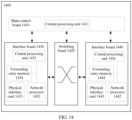
- FIG. 8 is a schematic diagram of a first PE device 400 according to an embodiment of this application.
- the first PE device 400 may be the PE 1-1 in FIG. 2 and be configured to perform the method shown in FIG. 3 , FIG. 6 , or FIG. 7 .
- a customer edge CE device is connected to a first interface of the first PE device over a first link, and the CE device is connected to a second interface of a second PE device over a second link.
- the first PE device 400 includes a processing module 401 and a sending module 402.
- the processing module 401 is configured to generate a first message, where the first message carries a first Media Access Control/Internet Protocol advertisement route MAC/IP advertisement route and a virtual local area network VLAN identifier, the first MAC/IP advertisement route includes a MAC address and an Ethernet segment identifier ESI used to identify an Ethernet segment ES, the MAC address included in the first MAC/IP advertisement route is a MAC address of the CE device or a MAC address of a terminal device managed by the CE device, the Ethernet segment ES includes the first link and the second link, and the VLAN identifier is used to indicate a VLAN to which the MAC address included in the first MAC/IP advertisement route belongs.
- the first message carries a first Media Access Control/Internet Protocol advertisement route MAC/IP advertisement route and a virtual local area network VLAN identifier
- the first MAC/IP advertisement route includes a MAC address and an Ethernet segment identifier ESI used to identify an Ethernet segment ES
- the sending module 402 is configured to send the first message to the second PE device, where the first MAC/IP advertisement route and the VLAN identifier are used by the second PE device to generate a first MAC forwarding entry, the first MAC forwarding entry includes the MAC address included in the first MAC/IP advertisement route and the VLAN identifier, an outbound interface identifier included in the first MAC forwarding entry is an identifier of the second interface, and the first MAC forwarding entry is used by the second PE device to forward, to the CE device, a packet whose destination MAC address is the MAC address included in the first MAC/IP advertisement route.
- the first PE device when the second PE device does not learn a MAC route from the CE device and cannot obtain valid VLAN information, the first PE device notifies the second PE device of the MAC route learned from the CE device and the VLAN identifier.
- the second PE device can generate the first MAC forwarding entry based on the received MAC route and VLAN identifier.
- the second PE device may directly forward the data stream to the CE device over the second link based on the first MAC forwarding entry.
- the CE device forwards the data stream to the terminal device.
- a PE device may learn the VLAN identifier by using a control plane.
- the second PE device cannot directly learn the VLAN identifier from the CE device.
- the second PE device may learn the VLAN identifier from the first PE device.
- the second PE device may forward traffic to the CE device based on the VLAN identifier. For example, when the CE device accesses the second PE device by using an Ethernet tag (tag) or through Ethernet tag termination, the second PE can forward the traffic to the CE device based on the VLAN identifier.
- tag Ethernet tag
- the first message is a first Border Gateway Protocol update BGP update message
- the first BGP update message includes a VLAN attribute field used to carry the VLAN identifier.
- a specific format of the first BGP update message and a format of the VLAN attribute field (for example, fields or extension fields to be used), refer to descriptions of corresponding parts in the foregoing method embodiments. Details are not described herein again.
- the VLAN attribute is extended in a BGP update message, thereby effectively implementing VLAN information advertisement by using an existing protocol.
- the first PE device 400 further includes a receiving module 403.
- the receiving module 403 is configured to receive a second message sent by the second PE device.
- the second message carries a second MAC/IP advertisement route, a next hop network address, and the VLAN identifier.
- the second MAC/IP advertisement route includes a destination MAC address and the Ethernet segment identifier ESI.
- the destination MAC address in the second MAC/IP advertisement route is the same as the MAC address included in the first MAC/IP advertisement route.
- the next hop network address carried in the second message is a network address of the second PE device.
- the Ethernet segment identifier ESI is used by the first PE device to determine that the first PE device is connected to the CE device through the first interface.
- the determined first interface, the MAC address included in the second MAC/IP advertisement route, and the VLAN identifier are used by the first PE device to generate a second MAC forwarding entry, the second MAC forwarding entry includes the MAC address included in the second MAC/IP advertisement route, an outbound interface identifier included in the second forwarding entry is an identifier of the first interface, and the second MAC forwarding entry is used by the first PE device to forward an entry of a packet whose destination MAC address is the MAC address included in the second MAC/IP advertisement route.
- the processing module 401 is further configured to generate a third MAC forwarding entry based on the MAC address included in the second MAC/IP advertisement route and the network address of the second PE device.
- the third MAC forwarding entry includes the MAC address included in the second MAC/IP advertisement route, a next hop network address included in the third MAC forwarding entry is the network address of the second PE device, and when the first link is faulty, the third MAC forwarding entry is used by the first PE device to forward an entry of a packet whose destination MAC address is the MAC address included in the second MAC/IP advertisement route.
- the first PE device After generating the third MAC forwarding entry and the fourth MAC forwarding entry, the first PE device implements fast reroute FRR based on the third MAC forwarding entry and the fourth MAC forwarding entry.
- the first PE device receives known unicast traffic (a data packet whose destination MAC address is the MAC address included in the second MAC/IP advertisement route)
- the first PE device queries a MAC forwarding table; and when the first link normally works, directly forwards the packet to the terminal device by using the CE device according to an instruction of the third MAC forwarding entry.
- the first PE device When the first link is faulty, after the first PE device receives the known unicast traffic, the first PE device queries the MAC forwarding table, and forwards the traffic to the second PE device according to an instruction of a secondary forwarding entry, in other words, according to an instruction of the fourth MAC forwarding entry; and the second PE device forwards the traffic to the CE device, thereby increasing a failure convergence speed.
- the second message further carries instruction information.
- the processing module 401 is further configured to: after the receiving module receives the second message sent by the second PE device, skip sending, to the second PE device according to the instruction information, the VLAN identifier and a MAC/IP advertisement route that arrives at the MAC address included in the second MAC/IP advertisement route. Therefore, a packet loop is avoided.
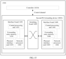
- FIG. 9 is a schematic diagram of a second PE device 500 according to an embodiment of this application.
- the second PE device 500 may be the PE 1-2 in FIG. 2 and be configured to perform the method shown in FIG. 3 , FIG. 6 , or FIG. 7 .
- a customer edge CE device is connected to a first interface of the first PE device over a first link, and the CE device is connected to a second interface of the second PE device over a second link.
- the second PE device 500 includes a receiving module 501 and a processing module 502.
- the receiving module 501 is configured to receive a first message sent by the first PE device, where the first message carries a first Media Access Control/Internet Protocol advertisement route MAC/IP advertisement route and a first VLAN identifier, the first MAC/IP advertisement route includes a MAC address and an Ethernet segment identifier ESI used to identify an Ethernet segment ES, the MAC address included in the first MAC/IP advertisement route is a MAC address of the CE device or a MAC address of a terminal device managed by the CE device, the Ethernet segment ES includes the first link and the second link, and the first VLAN identifier is used to indicate a VLAN to which the MAC address included in the first MAC/IP advertisement route belongs.
- the processing module 502 is configured to determine, based on the Ethernet segment identifier ESI carried in the first message received by the receiving module 501, that the second PE device is connected to the CE device through the second interface.
- the processing module 502 is further configured to generate a first MAC forwarding entry based on the determined second interface, the MAC address included in the first MAC/IP advertisement route, and the first VLAN identifier, where the first MAC forwarding entry includes the MAC address included in the first MAC/IP advertisement route and the first VLAN identifier, an outbound interface identifier included in the first MAC forwarding entry is an identifier of the second interface, and the first MAC forwarding entry is used by the second PE device to forward, to the CE device, a packet that carries the first VLAN identifier and whose destination MAC address is the MAC address included in the first MAC/IP advertisement route.
- the first PE device when the second PE device does not learn a MAC route from the CE device and cannot obtain information about a VLAN to which the terminal device belongs, the first PE device notifies the second PE device of a MAC route that arrives at the terminal device and an identifier of the VLAN to which the terminal device belongs.
- the second PE device can generate the first MAC forwarding entry based on the received MAC route and VLAN identifier.
- the second PE device may directly forward the data stream to the CE device over the second link based on the first MAC forwarding entry.
- the CE device forwards the data stream to the terminal device.
- a PE device may learn, by using a control plane, the VLAN information of the VLAN to which the terminal device belongs.
- the second PE device cannot directly learn the VLAN information of the terminal device from the CE device.
- the second PE device may learn the VLAN information of the terminal device from the first PE device. Further, the second PE device may forward, to the CE device based on the VLAN information of the terminal device, traffic that arrives at the terminal device. For example, when the CE device accesses the second PE device by using an Ethernet tag (tag) or through Ethernet tag termination, the second PE device cannot directly learn the VLAN information of the terminal device from the CE device.
- the first message further carries a next hop network address
- the next hop network address in the first message is a network address of the first PE device, for example, a loopback address of the first PE device.
- the processing module 502 is further configured to obtain the network address of the first PE device based on the first message.
- the processing module 502 is further configured to generate a second MAC forwarding entry based on the MAC address included in the first MAC/IP advertisement route and the network address of the first PE device.
- the second MAC forwarding entry includes the MAC address included in the first MAC/IP advertisement route, and a next hop network address included in the second MAC forwarding entry is the network address of the first PE device.
- the second MAC forwarding entry is used by the second PE to forward the packet that carries the first VLAN identifier and whose destination MAC address is the MAC address included in the first MAC/IP advertisement route.
- the second PE device When the second PE device receives known unicast traffic (a data packet whose destination MAC address is a MAC address of the terminal device) bound for the terminal device, the second PE device queries a MAC forwarding table; and when the second link is in a normal working state, directly forwards the packet to the terminal device over the second link by using the CE device according to an instruction of the first MAC forwarding entry.
- the second link is faulty and the second PE device receives the known unicast traffic (the data packet whose destination MAC address is the MAC address of the terminal device) bound for the terminal device
- the second PE device forwards the traffic to the first PE device according to an instruction of the second MAC forwarding entry; and the first PE device forwards the traffic to the terminal device, thereby increasing a failure convergence speed.
- the first message is a first Border Gateway Protocol update BGP update message
- the first BGP update message includes a VLAN attribute field used to carry the first VLAN identifier.
- a specific format of the first BGP update message and a format of the VLAN attribute field (for example, fields or extension fields to be used), refer to descriptions of corresponding parts in the foregoing method embodiments. Details are not described herein again.
- the VLAN attribute is extended in a BGP update message, thereby effectively implementing VLAN information advertisement by using an existing protocol.
- the second PE device further includes a sending module 503. After the processing module generates the first MAC forwarding entry based on the determined second interface, the MAC address included in the first MAC/IP advertisement route, and the first VLAN identifier,
- the processing module 502 is further configured to generate a second message. Specifically, the processing module 502 generates the second message based on the first message received by the receiving module 501.
- the second message carries a second MAC/IP advertisement route, a next hop network address, and the first VLAN identifier, the second MAC/IP advertisement route includes a MAC address and the Ethernet segment identifier ESI, and the MAC address included in the second MAC/IP advertisement route is the same as the MAC address included in the first MAC/IP advertisement route.
- the processing module 502 obtains the MAC address included in the first MAC/IP advertisement route carried in the first message, and encapsulates the MAC address into the second MAC/IP advertisement route carried in the second message.
- the next hop network address carried in the second message is a network address of the second PE device.
- the sending module 503 is further configured to send the second message to the first PE device, where the second message is used by the first PE device to generate a third MAC forwarding entry and a fourth MAC forwarding entry.
- the third MAC forwarding entry is used by the first PE device to forward a packet whose destination MAC address is the MAC address included in the second MAC/IP advertisement route, the third MAC forwarding entry includes the MAC address included in the second MAC/IP advertisement route and the first VLAN identifier, and an outbound interface identifier included in the third MAC forwarding entry is an identifier of the first interface.
- the fourth MAC forwarding entry is used by the first PE device to forward a packet whose destination MAC address is the MAC address included in the second MAC/IP advertisement route, the fourth MAC forwarding entry includes the MAC address included in the second MAC/IP advertisement route, and a next hop network address included in the fourth MAC forwarding entry is the network address of the second PE device.
- the second PE device after receiving the first message, the second PE device generates, on the control plane based on information carried in the first message, a local primary MAC routing entry and a local secondary MAC routing entry that is used for fast reroute. Further, the control plane delivers the primary MAC routing entry and the secondary MAC routing entry to a forwarding plane, and generates the first MAC forwarding entry and the second MAC forwarding entry that are used for fast reroute. In addition, after receiving the first message, the second PE device generates the local first MAC forwarding entry, and then returns the local MAC route to the first PE device, so that the first PE device generates a secondary MAC routing entry used to implement fast reroute.
- the MAC route learned by the first PE device from the CE device may be used as a local MAC route, namely, a primary MAC route.
- a link that connects the first PE device and the CE device is faulty, for example, when the first link is faulty, the local MAC route of the first PE device is cancelled.
- the first PE device may generate the local MAC route again based on the second MAC/IP advertisement route and the first VLAN identifier that are notified by the second PE device, so as to instruct to forward traffic to the CE device. Therefore, after the first link is faulty and recovers again, a route can be quickly redirected, and fast failure convergence can be implemented.
- the second message further carries instruction information, and the instruction information is used to instruct the first PE device not to send, to the second PE device after the first PE device receives the second message, the first VLAN identifier and a MAC/IP advertisement route that arrives at the MAC address included in the second MAC/IP advertisement route, so as to avoid a packet loop.
- FIG. 10 is a schematic diagram of a first PE device 600 according to an embodiment of this application.
- the first PE device 600 may be the PE 1-1 in FIG. 2 and be configured to perform the method shown in FIG. 3 , FIG. 6 , or FIG. 7 .
- a customer edge CE device is connected to a first interface of the first PE device over a first link, and the CE device is connected to a second interface of a second PE device over a second link.
- the first PE device 600 includes an input interface 601, an output interface 602, a processor 603, and a memory 604.
- the input interface 601, the output interface 602, the processor 603, and the memory 604 may be connected to each other by using a bus system 605.
- the memory 604 is configured to store a program.
- the processor 603 is configured to execute the program in the memory 604, so as to control the input interface 601 to receive a signal, control the output interface 602 to send a signal, and implement steps and functions implemented by the first PE device in the implementation corresponding to FIG. 3 , FIG. 6 , or FIG. 7 . Details are not described herein again.
- the input interface 601, the output interface 602, and the processor 603 refer to specific descriptions of the receiving module 403, the sending module 402, and the processing module 401 in the implementation in FIG. 8 . Details are not described herein again.
- FIG. 11 is a schematic diagram of a second PE device 700 according to an embodiment of this application.
- the second PE device 700 may be the PE 1-2 in FIG. 2 and be configured to perform the method shown in FIG. 3 , FIG. 6 , or FIG. 7 .
- a customer edge CE device is connected to a first interface of the first PE device over a first link, and the CE device is connected to a second interface of the second PE device over a second link.
- the second PE device 700 includes an input interface 701, an output interface 702, a processor 703, and a memory 704.
- the input interface 701, the output interface 702, the processor 703, and the memory 704 may be connected to each other by using a bus system 705.
- the memory 704 is configured to store a program.
- the processor 703 is configured to execute the program in the memory 704, so as to control the input interface 701 to receive a signal, control the output interface 702 to send a signal, and implement steps and functions implemented by the second PE device in the implementation corresponding to FIG. 3 , FIG. 6 , or FIG. 7 . Details are not described herein again.
- the input interface 701, the output interface 702, and the processor 703 refer to specific descriptions of the receiving module 501, the sending module 503, and the processing module 502 in the implementation in FIG. 9 . Details are not described herein again.
- the processor 703 and the processor 603 each may be a central processing unit (Central Processing Unit, "CPU” for short), or may be another general-purpose processor, a digital signal processor (DSP), an application-specific integrated circuit (ASIC), a field programmable gate array (FPGA) or another programmable logic device, a discrete gate or transistor logic device, a discrete hardware component, or the like.
- the general-purpose processor may be a microprocessor, or the processor may be any conventional processor or the like.
- the memory 704 and the memory 604 may include a read-only memory and a random access memory, and respectively provide the processor 703 and the processor 603 with an instruction and data.
- a part of the memory 704 or the memory 604 may further include a nonvolatile random access memory.
- the memory 704 or the memory 604 may further store device type information.
- bus system 705 and the bus system 605 each may further include a power bus, a control bus, a status signal bus, and the like. However, for clarity of description, various buses are marked as the bus system in the figure.
- the steps in the method 300 may be respectively performed by using an integrated logic circuit of hardware or an instruction in a form of software in the processor 603 and the processor 703.
- the steps of the packet processing method disclosed with reference to the embodiments of this application may be directly performed by a hardware processor, or may be performed by using a combination of hardware in the processor and a software module.
- a software module may be located in a mature storage medium in the art, such as a random access memory, a flash memory, a read-only memory, a programmable read-only memory, an electrically erasable programmable memory, or a register.
- the storage medium is separately located in the memory 604 and the memory 704.
- the processor 603 reads information in the memory 604, and the processor 703 reads information in the memory 704.
- the steps in the method 300 are completed in combination with the hardware of the processor 603 and the processor 703. To avoid repetition, details are not described herein again.
- the processing module 401 in FIG. 8 may be implemented by the processor 603 in FIG. 10
- the sending module 402 may be implemented by the output interface 602 in FIG. 10
- the receiving module 403 may be implemented by the input interface 601 in FIG. 10
- the processing module 502 in FIG. 9 is implemented by the processor 703 in FIG. 11
- the sending module 503 may be implemented by the output interface 702 in FIG. 11
- the receiving module 501 may be implemented by the input interface 701 in FIG. 11 .
- FIG. 8 to FIG. 11 show only simplified designs of the first PE device and the second PE device.
- the first PE device and the second PE device each may include any quantity of interfaces, processors, memories, and the like.
- FIG. 12 is a schematic diagram of a hardware structure of another first PE device 1200 according to an embodiment of this application.
- the first PE device 1200 shown in FIG. 12 may be configured to perform corresponding steps performed by the first PE device in the method of the foregoing embodiment.
- the first PE device includes a main control board 1210, an interface board 1230, a switching board 1220, and an interface board 1240.
- the main control board 1210 is configured to complete functions such as system management, device maintenance, and protocol processing.
- the switching board 1220 is configured to exchange data between interface boards (the interface board is also referred to as a line card or a service board).
- the interface board 1230 and the interface board 1240 are configured to provide various service interfaces (for example, a point of synchronization (English: Point of Synchronization, POS) interface, a gigabit Ethernet (English: Gigabit Ethernet, GE) interface, and an asynchronous transfer mode (English: Asynchronous Transfer Mode, ATM) interface) and implement data packet forwarding.
- POS Point of Synchronization
- GE gigabit Ethernet
- ATM asynchronous Transfer Mode
- the main control board 1210, the interface board 1230, the interface board 1240, and the switching board 1220 are connected to a platform backboard for interworking.
- a central processing unit 1231 on the interface board 1230 is configured to: control and manage the interface board; and communicate with a central processing unit on the main control board.
- the central processing unit 1211 on the main control board 1210 generates a first message, and sends, by using a central processing unit on the interface board 1230, the first message to a second PE device connected to a physical interface card 1233.
- the first message carries a first MAC/IP advertisement route and a VLAN identifier
- the first MAC/IP advertisement route includes a MAC address and an Ethernet segment identifier ESI used to identify an Ethernet segment ES.
- the MAC address included in the first MAC/IP advertisement route is a MAC address of the CE device or a MAC address of a terminal device managed by the CE device.
- the Ethernet segment ES includes the first link and the second link, and the VLAN identifier is used to indicate a VLAN to which the MAC address included in the first MAC/IP advertisement route belongs.
- the first MAC/IP advertisement route and the VLAN identifier are used by the second PE device to generate a first MAC forwarding entry, the first MAC forwarding entry includes the MAC address included in the first MAC/IP advertisement route and the VLAN identifier, and an outbound interface identifier included in the first MAC forwarding entry is an identifier of the second interface.
- the first MAC forwarding entry is used by the first PE device to forward, to the CE device, a packet whose destination MAC address is the MAC address included in the first MAC/IP advertisement route.
- the central processing unit 1211 on the main control board 1210 is further configured to obtain, from the physical interface card 1233 on the interface board 1230, a second message sent by the second PE device.
- the second message carries a second MAC/IP advertisement route, a next hop network address, and the VLAN identifier.
- the second MAC/IP advertisement route includes a destination MAC address and the Ethernet segment identifier ESI.
- the destination MAC address in the second MAC/IP advertisement route is the MAC address included in the second MAC/IP advertisement route.
- the next hop network address carried in the second message is a network address of the second PE device, the Ethernet segment identifier ESI is used by the first PE device to determine that the first PE device is connected to the CE device through the first interface.
- the determined first interface, the MAC address included in the second MAC/IP advertisement route, and the VLAN identifier are used by the first PE device to generate a third MAC forwarding entry.
- the third MAC forwarding entry includes the MAC address included in the second MAC/IP advertisement route, and an outbound interface identifier included in the third MAC forwarding entry is an identifier of the first interface.
- the third MAC forwarding entry is used by the first PE device to forward a packet whose destination MAC address is the MAC address included in second MAC/IP advertisement route.
- the central processing unit 1211 on the main control board 1210 determines, based on the ESI, that the first PE device is connected to the CE device through the first interface; and generates the third MAC forwarding entry based on the determined first interface, the MAC address included in the second MAC/IP advertisement route, and the VLAN identifier.
- the central processing unit 1211 on the main control board 1210 sends the third MAC forwarding entry to a forwarding entry memory 1234 on the interface board 1230 by using the central processing unit 1231 on the interface board 1230.
- the forwarding entry memory 1234 on the interface board 1230 is configured to store the third MAC forwarding entry.
- the central processing unit 1231 on the interface board 1230 is configured to control a network memory 1232 to obtain a MAC forwarding entry in the forwarding entry memory 1234.
- the central processing unit 1231 is configured to control the network memory 1232 to receive and forward traffic by using the physical interface card 1233.
- the second PE device may have a same structure as the first PE device.
- the PE device may include one or more main control boards, and the plurality of main control boards may include a primary main control board and a secondary main control board.
- the PE device may not need a switching board, and the interface board is responsible for a service data processing function of an entire system.
- the PE device may include at least one switching board, and data is exchanged between a plurality of interface boards by using the switching board, so as to provide a large-capacity data exchange and processing capability. Therefore, a data access and processing capability of a PE device of a distributed architecture is better than that of a device of a centralized architecture.
- Use of a specific architecture depends on a specific networking deployment scenario. No limitation is imposed herein.
- FIG. 13 is a schematic diagram of a hardware structure of another first PE device 1300 according to an embodiment of this application.
- the first PE device 1300 shown in FIG. 13 may be configured to perform corresponding steps performed by the first PE device in the method of the foregoing embodiment.
- Such a product form of the first PE device 1300 is applicable to a network architecture (for example, software-defined networking (English: Software Defined Networking, SDN for short)) in which control and forwarding are separated.
- SDN software-defined networking
- the main control board 1210 of the first PE device 1200 shown in FIG. 12 is separated from the device to form a new independent physical device (namely, a controller 1210A shown in FIG. 13 ), and remaining components form another independent physical device (namely, a first PE forwarding device 1200A shown in FIG. 13 ).
- the controller 1210A interacts with the first PE forwarding device 1200A by using a control channel protocol.
- the control channel protocol may be the OpenFlow (English: OpenFlow) Protocol, the Path Computation Element Communication Protocol (English: Path Computation Element Communication Protocol, PCEP for short), the BGP, the Interface to the Routing System (English: Interface to the Routing System, I2RS for short), or the like.
- the first PE device 1300 in this embodiment compared with the embodiment corresponding to FIG. 12 includes the controller 1210A and the first PE forwarding device 1200A that are separated.
- the first PE device 1300 may also be considered as a system.
- the controller 1210A may be implemented based on a general-purpose physical server or a dedicated hardware structure.
- the controller includes a receiver, a processor, a transmitter, a random access memory (English: Random Access Memory, RAM), a read-only memory (English: Read-only Memory, ROM), and a bus (not shown in the figure).
- the processor is separately coupled to the receiver, the transmitter, the RAM, and the ROM by using the bus.
- BIOS Basic Input/output System
- BIOS Basic Input/output System
- bootloader English: bootloader
- the first PE forwarding device 1200A may be implemented based on a dedicated hardware structure.
- a function and a structure of the first PE forwarding device is consistent with functions and structures of the interface board 1230, the interface board 1240, and the switching board 1220 in FIG. 12 , so as to perform corresponding functions and steps.
- the first PE forwarding device may be a virtual first PE forwarding device implemented based on the general-purpose physical server and a network functions virtualization (English: Network Functions Virtualization, NFV for short) technology, and the virtual first PE forwarding device is a virtual router.
- the interface board, the switching board, and the processor that are included in the foregoing physical first PE forwarding device in the embodiment of the first PE forwarding device can be considered as an interface resource, a network resource, and a processing resource that are allocated by the physical first PE forwarding device to the virtual first PE forwarding device by using a general-purpose physical server in a virtual environment.
- a general-purpose physical server for details of implementing functions or steps of the first PE forwarding device by using the general-purpose physical server, or for details of implementing functions or steps of the first PE forwarding device by using the general-purpose physical server and the NFV technology, refer to the embodiment in FIG. 10 .
- controller 1210A and the first PE forwarding device 1200A in the first PE device 1300 may implement various functions and steps implemented by the first PE device in the method embodiments. For brevity, details are not described herein again.
- FIG. 14 provides a schematic diagram of a hardware structure of another second PE device 1400 according to an embodiment of this application.
- the second PE device 1400 shown in FIG. 14 may be configured to perform corresponding steps performed by the second PE device in the method of the foregoing embodiment.
- the second PE device includes a main control board 1410, an interface board 1430, a switching board 1420, and an interface board 1440.
- the main control board 1410 is configured to complete functions such as system management, device maintenance, and protocol processing.
- the switching board 1420 is configured to exchange data between interface boards (the interface board is also referred to as a line card or a service board).
- the interface board 1430 and the interface board 1440 are configured to provide various service interfaces (for example, a POS interface, a GE interface, and an ATM interface) and forward a data packet.
- a central processing unit 1431 on the interface board 1430 is configured to: control and manage the interface board; and communicate with a central processing unit on the main control board.
- a physical interface card 1433 on the interface board 1430 receives a first message sent by a first PE device, where the first message carries a first MAC/IP advertisement route and a first VLAN identifier, the first MAC/IP advertisement route includes a MAC address and an Ethernet segment identifier ESI used to identify an Ethernet segment ES, the MAC address included in the first MAC/IP advertisement route is a MAC address of the CE device or a MAC address of a terminal device managed by the CE device, the Ethernet segment ES includes the first link and the second link, and the first VLAN identifier is used to indicate a VLAN to which the MAC address included in the first MAC/IP advertisement route belongs.
- the first MAC/IP advertisement route and the first VLAN identifier are sent to the central processing unit 1411 on the main control board 1410 by using the central processing unit 1431 on the interface board 1430.
- the central processing unit 1411 on the main control board 1410 is configured to: obtain the first MAC/IP advertisement route and the first VLAN identifier; and determine, based on the central processing unit 1411 on the main control board 1410 and based on the ESI, that the second PE device is connected to the CE device through the second interface. Further, the central processing unit 1411 generates a first MAC forwarding entry based on the determined second interface, the MAC address included in the first MAC/IP advertisement route, and the first VLAN identifier.
- the first MAC forwarding entry includes the MAC address included in the first MAC/IP advertisement route and the first VLAN identifier, an outbound interface identifier included in the first MAC forwarding entry is an identifier of the second interface, and the first MAC forwarding entry is used by the second PE device to forward, to the CE device, a packet that carries the first VLAN identifier and whose destination MAC address is the MAC address included in the first MAC/IP advertisement route.
- the central processing unit 1411 on the main control board 1410 sends the first MAC forwarding entry to a forwarding entry memory 1434 on the interface board 1430 by using the central processing unit 1431 on the interface board 1430.
- the forwarding entry memory 1434 on the interface board 1430 is configured to store the first MAC forwarding entry.
- the central processing unit 1431 on the interface board 1430 is configured to control a network memory 1432 to obtain the MAC forwarding entry in the forwarding entry memory 1434.
- the central processing unit 1431 is configured to control the network memory 1432 to receive and send traffic by using the physical interface card 1433.
- the central processing unit 1411 on the main control board 1410 is further configured to control the interface board 1430 to forward and process traffic.
- FIG. 15 is a schematic diagram of a hardware structure of another second PE device 1500 according to an embodiment of this application.
- the second PE device 1500 shown in FIG. 15 may be configured to perform corresponding steps performed by the second PE device in the method of the foregoing embodiment.
- Such a product form of the second PE device 1500 is applicable to a network architecture (for example, SDN) in which control and forwarding are separated.
- SDN the main control board 1410 of the second PE device 1400 shown in FIG. 14 is separated from the device to form a new independent physical device (namely, a controller 1410A shown in FIG. 15 ), and remaining components form another independent physical device (namely, a second PE forwarding device 1400A shown in FIG. 15 ).
- the controller 1410A interacts with the second PE forwarding device 1400A by using a control channel protocol.
- the control channel protocol may be the OpenFlow Protocol, the PCEP, the BGP, the I2RS, or the like.
- the second PE device 1500 in this embodiment compared with the embodiment corresponding to FIG. 14 includes the controller 1410A and the second PE forwarding device 1400A that are separated.
- the second PE device 1500 may also be considered as a system.
- the controller 1410A may be implemented based on a general-purpose physical server or a dedicated hardware structure.
- the controller includes a receiver, a processor, a transmitter, a RAM, a ROM, and a bus (not shown in the figure).
- the processor is separately coupled to the receiver, the transmitter, the RAM, and the ROM by using the bus.
- a BIOS built in the ROM or a bootloader in an embedded system is used to boot the system to start, and boot the controller to enter a normal running state. After entering the normal running state, the controller runs an application and an operating system in the RAM, so that the processor performs all functions and steps of the main control board 1410 in FIG. 14 .
- the second PE forwarding device 1400A may be implemented based on a dedicated hardware structure.
- a function and a structure of the second PE forwarding device is consistent with functions and structures of the interface board 1430, the interface board 1440, and the switching board 1420 in FIG. 14 , so as to perform corresponding functions and steps.
- the second PE forwarding device may be a virtual second PE forwarding device implemented based on the general-purpose physical server and a network functions virtualization (English: Network Functions Virtualization, NFV for short) technology, and the virtual second PE forwarding device is a virtual router.
- the interface board, the switching board, and the processor that are included in the foregoing physical second PE forwarding device in the embodiment of the second PE forwarding device can be considered as an interface resource, a network resource, and a processing resource that are allocated by the physical second PE forwarding device to the virtual second PE forwarding device by using a general-purpose physical server in a virtual environment.
- a general-purpose physical server for details of implementing functions or steps of the second PE forwarding device by using the general-purpose physical server, or for details of implementing functions or steps of the second PE forwarding device by using the general-purpose physical server and the NFV technology, refer to the embodiment in FIG. 11 .
- controller 1410A and the second PE forwarding device 1400A in the second PE device 1500 may implement various functions and steps implemented by the second PE device in the method embodiments. For brevity, details are not described herein again.
- This application further provides a communications system, including a first PE device and a second PE device.
- the first PE device may be the first PE device provided in the embodiment corresponding to FIG. 8 , FIG. 10 , FIG. 12 , or FIG. 13 .
- the second PE device may be the second PE device provided in the embodiment corresponding to FIG. 9 , FIG. 11 , FIG. 14 , or FIG. 15 .
- the communications system is configured to perform the method 300 in the embodiments corresponding to FIG. 2 to FIG. 7 .
- sequence numbers of the foregoing processes do not mean execution sequences in various embodiments of this application.
- the execution sequences of the processes should be determined according to functions and internal logic of the processes, and should not be construed as any limitation on the implementation processes of the embodiments of this application.
- All or some of the foregoing embodiments may be implemented through software, hardware, firmware, or any combination thereof.
- the embodiments may be implemented fully or partially in a form of a computer program product.
- the computer program product includes one or more computer instructions.
- the computer may be a general-purpose computer, a dedicated computer, a computer network, or other programmable apparatuses.
- the computer instructions may be stored in a computer readable storage medium, or may be transmitted from a computer readable storage medium to another computer readable storage medium.
- the computer instructions may be transmitted from a website, computer, server, or data center to another website, computer, server, or data center in a wired (for example, a coaxial cable, an optical fiber, or a digital subscriber line (DSL)) or wireless (for example, infrared, radio, or microwave) manner.
- the computer readable storage medium may be any usable medium accessible by the computer, or a data storage device, such as a server or a data center, integrating one or more usable media.
- the usable medium may be a magnetic medium (for example, a floppy disk, a hard disk, or a magnetic tape), an optical medium (for example, a DVD), a semiconductor medium (for example, a solid state disk Solid State Disk (SSD)), or the like.
- a magnetic medium for example, a floppy disk, a hard disk, or a magnetic tape
- an optical medium for example, a DVD
- a semiconductor medium for example, a solid state disk Solid State Disk (SSD)
- SSD solid state disk Solid State Disk
Landscapes
- Engineering & Computer Science (AREA)
- Computer Networks & Wireless Communication (AREA)
- Signal Processing (AREA)
- Computer Security & Cryptography (AREA)
- Data Exchanges In Wide-Area Networks (AREA)
Claims (15)
- Paketverarbeitungsverfahren, wobei das Verfahren auf eine Ethernet-Virtual-Private-Network-, EVPN-, Multi-Homing-Konfiguration angewendet wird, die eine Customer-Edge-, CE-, Vorrichtung umfasst, die über eine erste Verknüpfung mit einer ersten Schnittstelle einer ersten Provider-Edge-, PE-, Vorrichtung verbunden ist, wobei die CE-Vorrichtung ferner über eine zweite Verknüpfung mit einer zweiten Schnittstelle einer zweiten PE-Vorrichtung verbunden ist, und das Verfahren Folgendes umfasst:Empfangen (303), durch die zweite PE-Vorrichtung, einer ersten Nachricht, die durch die erste PE-Vorrichtung gesendet wird, wobei die erste Nachricht eine erste Media-Access-Control/Internet-Protocol-, MAC/IP-, Advertisement-Route und eine erste VLAN-Kennung trägt, die erste MAC/IP-Advertisement-Route eine erste MAC-Adresse und eine Ethernet-Segmentkennung, ESI, die zur Identifizierung eines Ethernet-Segments, ES, verwendet wird, umfasst, wobei das ES die erste Verknüpfung und die zweite Verknüpfung umfasst und die erste MAC-Adresse eine MAC-Adresse der CE-Vorrichtung oder eine MAC-Adresse einer Endgerätevorrichtung, die durch die CE-Vorrichtung verwaltet wird, ist, und die erste VLAN-Kennung verwendet wird, um ein VLAN anzugeben, zu dem die erste MAC-Adresse gehört;Bestimmen (304), durch die zweite PE-Vorrichtung basierend auf der ESI, dass die zweite PE-Vorrichtung über die zweite Schnittstelle mit der CE-Vorrichtung verbunden ist; undErzeugen (305), durch die zweite PE-Vorrichtung, eines ersten MAC-Weiterleitungseintrags basierend auf der bestimmten zweiten Schnittstelle, der ersten MAC-Adresse und der ersten VLAN-Kennung, wobei der erste MAC-Weiterleitungseintrag die erste MAC-Adresse, die erste VLAN-Kennung und eine Kennung der ausgehenden Schnittstelle, die einer Kennung der zweiten Schnittstelle entspricht, umfasst und der erste MAC-Weiterleitungseintrag durch die zweite PE-Vorrichtung verwendet wird, um an die CE-Vorrichtung ein Paket weiterzuleiten, das die erste VLAN-Kennung trägt und dessen Ziel-MAC-Adresse die erste MAC-Adresse ist.
- Verfahren nach Anspruch 1, wobei die erste Nachricht ferner eine Next-Hop-Netzwerkadresse trägt, die Next-Hop-Netzwerkadresse in der ersten Nachricht eine Netzwerkadresse der ersten PE-Vorrichtung ist und das Verfahren ferner Folgendes umfasst:Erlangen, durch die zweite PE-Vorrichtung, der Netzwerkadresse der ersten PE-Vorrichtung basierend auf der ersten Nachricht; undErzeugen, durch die zweite PE-Vorrichtung, eines zweiten MAC-Weiterleitungseintrags basierend auf der ersten MAC-Adresse und der Netzwerkadresse der ersten PE-Vorrichtung, wobei der zweite MAC-Weiterleitungseintrag die erste MAC-Adresse und eine Kennung der ausgehenden Schnittstelle, die eine ausgehende Schnittstelle identifiziert, die auf die erste PE-Vorrichtung zeigt, umfasst; undwenn die zweite Verknüpfung ausfällt, der zweite MAC-Weiterleitungseintrag durch die zweite PE-Vorrichtung verwendet wird, um das Paket weiterzuleiten, das die erste VLAN-Kennung trägt und dessen Ziel-MAC-Adresse die erste MAC-Adresse ist.
- Verfahren nach Anspruch 1 oder 2, wobei das Verfahren nach dem Erzeugen, durch die zweite PE-Vorrichtung, eines ersten MAC-Weiterleitungseintrags basierend auf der bestimmten zweiten Schnittstelle, der umfassten ersten MAC-Adresse und der ersten VLAN-Kennung ferner Folgendes umfasst:Empfangen, durch die zweite PE-Vorrichtung, eines ersten Pakets, das eine zweite VLAN-Kennung trägt, wobei eine Ziel-MAC-Adresse des ersten Pakets die erste MAC-Adresse ist;Ersetzen, durch die zweite PE-Vorrichtung, der zweiten VLAN-Kennung, die im ersten Paket getragen wird, durch die erste VLAN-Kennung basierend auf dem ersten MAC-Weiterleitungseintrag, um ein zweites Paket zu erlangen, das die erste VLAN-Kennung trägt; undSenden, durch die zweite PE-Vorrichtung, des zweiten Pakets an die CE-Vorrichtung.
- Verfahren nach einem der Ansprüche 1 bis 3, wobei das Verfahren nach dem Empfangen, durch die zweite PE-Vorrichtung, einer ersten Nachricht, die durch die erste PE-Vorrichtung gesendet wird, ferner Folgendes umfasst:Erzeugen, durch die zweite PE-Vorrichtung, einer zweiten Nachricht, wobei die zweite Nachricht eine zweite MAC/IP-Advertisement-Route, eine Next-Hop-Netzwerkadresse und die erste VLAN-Kennung trägt, die zweite MAC/IP-Advertisement-Route eine zweite MAC-Adresse und die ESI umfasst, die zweite MAC-Adresse dieselbe wie die erste MAC-Adresse ist und die Next-Hop-Netzwerkadresse, die in der zweiten Nachricht getragen wird, eine Netzwerkadresse der zweiten PE-Vorrichtung ist; undSenden, durch die zweite PE-Vorrichtung, der zweiten Nachricht an die erste PE-Vorrichtung.
- Zweite Provider-Edge-, PE-, Vorrichtung (500), wobei die Vorrichtung auf eine Ethernet-Virtual-Private-Network-, EVPN-, Multi-Homing-Konfiguration angewendet wird, die eine Customer-Edge-, CE-, Vorrichtung umfasst, die über eine erste Verknüpfung mit einer ersten Schnittstelle einer ersten Provider-Edge-, PE-, Vorrichtung verbunden ist, wobei die CE-Vorrichtung ferner über eine zweite Verknüpfung mit einer zweiten Schnittstelle der zweiten PE-Vorrichtung verbunden ist, und die zweite PE-Vorrichtung Folgendes umfasst:ein Empfangsmodul (501), das dazu konfiguriert ist, eine erste Nachricht zu empfangen, die durch die erste PE-Vorrichtung gesendet wird, wobei die erste Nachricht eine erste Media-Access-Control/Internet-Protocol-, MAC/IP-, Advertisement-Route und eine erste Virtual-Local-Area-Network-, VLAN-, Kennung trägt, die erste MAC/IP-Advertisement-Route eine erste MAC-Adresse und eine Ethernet-Segmentkennung, ESI, umfasst, die zur Identifizierung eines Ethernet-Segments, ES, verwendet wird, wobei das ES die erste Verknüpfung und die zweite Verknüpfung umfasst und die erste MAC-Adresse eine MAC-Adresse der CE-Vorrichtung oder eine MAC-Adresse einer Endgerätevorrichtung, die durch die CE-Vorrichtung verwaltet wird, ist, und die erste VLAN-Kennung verwendet wird, um ein VLAN anzugeben, zu dem die erste MAC-Adresse gehört; undein Verarbeitungsmodul (502), das dazu konfiguriert ist, basierend auf der ESI zu bestimmen, dass die zweite PE-Vorrichtung über die zweite Schnittstelle mit der CE-Vorrichtung verbunden ist, wobeidas Verarbeitungsmodul (502) ferner dazu konfiguriert ist, einen ersten MAC-Weiterleitungseintrag basierend auf der bestimmten zweiten Schnittstelle, der ersten MAC-Adresse und der ersten VLAN-Kennung zu erzeugen, wobei der erste MAC-Weiterleitungseintrag die erste MAC-Adresse, die erste VLAN-Kennung und eine Kennung der ausgehenden Schnittstelle, die einer Kennung der zweiten Schnittstelle entspricht, umfasst und der erste MAC-Weiterleitungseintrag durch die zweite PE-Vorrichtung verwendet wird, um an die CE-Vorrichtung ein Paket weiterzuleiten, das die erste VLAN-Kennung trägt und dessen Ziel-MAC-Adresse die erste MAC-Adresse ist.
- Zweite PE-Vorrichtung nach Anspruch 5, wobei die erste Nachricht ferner eine Next-Hop-Netzwerkadresse trägt und die Next-Hop-Netzwerkadresse in der ersten Nachricht eine Netzwerkadresse der ersten PE-Vorrichtung ist;das Verarbeitungsmodul (502) ferner dazu konfiguriert ist, die Netzwerkadresse der ersten PE-Vorrichtung basierend auf der ersten Nachricht zu erlangen;das Verarbeitungsmodul (502) ferner dazu konfiguriert ist, einen zweiten MAC-Weiterleitungseintrag basierend auf der ersten MAC-Adresse und der Netzwerkadresse der ersten PE-Vorrichtung zu erzeugen, wobei der zweite MAC-Weiterleitungseintrag die erste MAC-Adresse und eine Kennung der ausgehenden Schnittstelle, die eine ausgehende Schnittstelle identifiziert, die auf die erste PE-Vorrichtung zeigt, umfasst; undwenn die zweite Verknüpfung ausfällt, der zweite MAC-Weiterleitungseintrag durch die zweite PE-Vorrichtung verwendet wird, um das Paket weiterzuleiten, das die erste VLAN-Kennung trägt und dessen Ziel-MAC-Adresse die erste MAC-Adresse ist.
- Zweite PE-Vorrichtung nach Anspruch 5 oder 6, wobei die erste Nachricht eine erste Border-Gateway-Protocol-, BGP-, Update-Nachricht ist und die erste BGP-Update-Nachricht ein VLAN-Attributfeld umfasst, das zum Tragen der ersten VLAN-Kennung verwendet wird.
- Zweite PE-Vorrichtung nach einem der Ansprüche 5 bis 7, wobei die zweite PE-Vorrichtung ferner ein Sendemodul (503) umfasst und nachdem das Verarbeitungsmodul (502) den ersten MAC-Weiterleitungseintrag basierend auf der bestimmten zweiten Schnittstelle, der ersten MAC-Adresse und der ersten VLAN-Kennung erzeugt hat,ist das Empfangsmodul (501) ferner dazu konfiguriert, ein erstes Paket zu empfangen, das eine zweite VLAN-Kennung trägt, wobei eine Ziel-MAC-Adresse des ersten Pakets die erste MAC-Adresse ist;ist das Verarbeitungsmodul (502) ferner dazu konfiguriert, die zweite VLAN-Kennung, die im zweiten Paket getragen wird, durch die erste VLAN-Kennung basierend auf dem ersten MAC-Weiterleitungseintrag zu ersetzen, um ein zweites Paket zu erlangen, das die erste VLAN-Kennung trägt; undist das Sendemodul (503) dazu konfiguriert, das zweite Paket an die CE-Vorrichtung zu senden.
- Zweite PE-Vorrichtung nach einem der Ansprüche 5 bis 8, wobei, nachdem das Empfangsmodul (501) die erste Nachricht empfangen hat, die durch die erste PE-Vorrichtung gesendet wurde,das Verarbeitungsmodul (502) ferner dazu konfiguriert ist, eine zweite Nachricht zu erzeugen, wobei die zweite Nachricht eine zweite MAC/IP-Advertisement-Route, eine Next-Hop-Netzwerkadresse und die erste VLAN-Kennung trägt, die zweite MAC/IP-Advertisement-Route eine zweite MAC-Adresse und die ESI umfasst, die zweite MAC-Adresse dieselbe wie die erste MAC-Adresse ist und die Next-Hop-Netzwerkadresse, die in der zweiten Nachricht getragen wird, eine Netzwerkadresse der zweiten PE-Vorrichtung ist;das Sendemodul (503) ferner dazu konfiguriert ist, die zweite Nachricht an die erste PE-Vorrichtung zu senden.
- System, umfassend eine erste Provider-Edge-, PE-, Vorrichtung, eine zweite PE-Vorrichtung und eine Customer-Edge-, CE-, Vorrichtung, wobei die CE-Vorrichtung über eine erste Verknüpfung mit einer ersten Schnittstelle der ersten PE-Vorrichtung verbunden ist und die CE-Vorrichtung ferner über eine zweite Verknüpfung mit einer zweiten Schnittstelle der zweiten PE-Vorrichtung verbunden ist; wobei
die erste PE-Vorrichtung zu Folgendem konfiguriert ist:Erzeugen einer ersten Nachricht, wobei die erste Nachricht eine erste Border-Gateway-Protocol-, BGP-, Update-Nachricht ist, die eine erste Media-Access-Control/Internet-Protocol-, MAC/IP-, Advertisement-Route und ein Virtual-Local-Area-Network-, VLAN-, Attribut, das verwendet wird, um eine VLAN-Kennung zu tragen, trägt, die erste MAC/IP-Advertisement-Route eine erste MAC-Adresse und eine Ethernet-Segmentkennung, ESI, die verwendet wird, um ein Ethernet-Segment, ES, zu identifizieren, umfasst, wobei die erste MAC-Adresse eine MAC-Adresse der CE-Vorrichtung oder eine MAC-Adresse einer Endgerätevorrichtung, die durch die CE-Vorrichtung verwaltet wird, ist, das ES die erste Verknüpfung und die zweite Verknüpfung umfasst und die VLAN-Kennung ein VLAN angibt, zu dem die erste MAC-Adresse gehört; undSenden der ersten Nachricht an die zweite PE-Vorrichtung;die zweite PE-Vorrichtung zu Folgendem konfiguriert ist:Empfangen der ersten Nachricht, die durch die erste PE-Vorrichtung gesendet wird; undErzeugen eines ersten MAC-Weiterleitungseintrags, wobei der erste MAC-Weiterleitungseintrag die erste MAC-Adresse, die erste VLAN-Kennung und eine Kennung der ausgehenden Schnittstelle, die einer Kennung der zweiten Schnittstelle entspricht, umfasst und der erste MAC-Weiterleitungseintrag durch die zweite PE-Vorrichtung verwendet wird, um an die CE-Vorrichtung ein Paket weiterzuleiten, das die erste VLAN-Kennung trägt und dessen Ziel-MAC-Adresse die erste MAC-Adresse ist. - System nach Anspruch 10, wobei die zweite PE-Vorrichtung ferner zu Folgendem konfiguriert ist:Erlangen der Netzwerkadresse der ersten PE-Vorrichtung basierend auf der ersten Nachricht; undErzeugen eines zweiten MAC-Weiterleitungseintrags basierend auf der ersten MAC-Adresse und der Netzwerkadresse der ersten PE-Vorrichtung, wobei der zweite MAC-Weiterleitungseintrag die erste MAC-Adresse und eine Kennung der ausgehenden Schnittstelle, die eine ausgehende Schnittstelle identifiziert, die auf die erste PE-Vorrichtung zeigt, umfasst; undwenn die zweite Verknüpfung ausfällt, Weiterleiten des Pakets, das die erste VLAN-Kennung trägt und dessen Ziel-MAC-Adresse die erste MAC-Adresse ist, gemäß dem zweiten MAC-Weiterleitungseintrag.
- System nach Anspruch 10 oder 11, wobei die zweite PE-Vorrichtung ferner zu Folgendem konfiguriert ist:Empfangen eines ersten Pakets, das eine zweite VLAN-Kennung trägt, wobei eine Ziel-MAC-Adresse des ersten Pakets die erste MAC-Adresse ist;Ersetzen der zweiten VLAN-Kennung, die im ersten Paket getragen wird, durch die erste VLAN-Kennung basierend auf dem ersten MAC-Weiterleitungseintrag, um ein zweites Paket zu erlangen, das die erste VLAN-Kennung trägt; undSenden des zweiten Pakets an die CE-Vorrichtung.
- System nach einem der Ansprüche 10 bis 12, wobei die zweite PE-Vorrichtung ferner zu Folgendem konfiguriert ist:Erzeugen einer zweiten Nachricht, wobei die zweite Nachricht eine zweite MAC/IP-Advertisement-Route, eine Next-Hop-Netzwerkadresse und die erste VLAN-Kennung trägt, die zweite MAC/IP-Advertisement-Route die erste MAC-Adresse umfasst und die Next-Hop-Netzwerkadresse, die in der zweiten Nachricht getragen wird, eine Netzwerkadresse der zweiten PE-Vorrichtung ist; undSenden der zweiten Nachricht an die erste PE-Vorrichtung.
- System nach einem der Ansprüche 10 bis 13, wobei die erste VLAN-Kennung eine Service-VLAN-, S-VLAN-, Kennung umfasst.
- Computerprogrammprodukt, das ein Computerprogramm umfasst, das, wenn das Programm durch einen Computer ausgeführt wird, den Computer dazu veranlasst, das Verfahren nach einem der Ansprüche 1 bis 4 durchzuführen.
Applications Claiming Priority (2)
| Application Number | Priority Date | Filing Date | Title |
|---|---|---|---|
| CN201710151472.0A CN108574630B (zh) | 2017-03-14 | 2017-03-14 | Evpn报文处理方法、设备及系统 |
| PCT/CN2017/115821 WO2018166253A1 (zh) | 2017-03-14 | 2017-12-13 | Evpn报文处理方法、设备及系统 |
Publications (4)
| Publication Number | Publication Date |
|---|---|
| EP3588872A1 EP3588872A1 (de) | 2020-01-01 |
| EP3588872A4 EP3588872A4 (de) | 2020-01-22 |
| EP3588872B1 true EP3588872B1 (de) | 2024-07-31 |
| EP3588872C0 EP3588872C0 (de) | 2024-07-31 |
Family
ID=63522658
Family Applications (1)
| Application Number | Title | Priority Date | Filing Date |
|---|---|---|---|
| EP17901185.3A Active EP3588872B1 (de) | 2017-03-14 | 2017-12-13 | Verfahren, vorrichtung, system und computerprogramm-produkt zur vpn-paketverarbeitung |
Country Status (4)
| Country | Link |
|---|---|
| US (2) | US11394644B2 (de) |
| EP (1) | EP3588872B1 (de) |
| CN (2) | CN111726286A (de) |
| WO (1) | WO2018166253A1 (de) |
Families Citing this family (32)
| Publication number | Priority date | Publication date | Assignee | Title |
|---|---|---|---|---|
| US10536370B2 (en) * | 2017-08-08 | 2020-01-14 | Dell Products Lp | Method and system to avoid temporary traffic loss with BGP ethernet VPN multi-homing with data-plane MAC address learning |
| CN109104364B (zh) * | 2017-11-27 | 2020-11-06 | 新华三技术有限公司 | 一种指定转发者选举方法和装置 |
| CN110661701B (zh) * | 2018-06-30 | 2022-04-22 | 华为技术有限公司 | 一种避免环路的通信方法、设备和系统 |
| CN110912795B (zh) * | 2018-09-14 | 2022-04-15 | 中兴通讯股份有限公司 | 一种传输控制方法、节点、网络系统及存储介质 |
| CN114598626A (zh) | 2019-02-25 | 2022-06-07 | 华为技术有限公司 | 报文处理的方法和网关设备 |
| CN110113260B (zh) * | 2019-04-28 | 2021-07-06 | 新华三技术有限公司 | 一种转发表更新方法及装置 |
| WO2020230146A1 (en) * | 2019-05-15 | 2020-11-19 | Telefonaktiebolaget Lm Ericsson (Publ) | Method and apparatus for layer 2 route calculation in a route reflector network device |
| US11388084B2 (en) * | 2019-07-17 | 2022-07-12 | Cisco Technology, Inc. | Ethernet virtual private network attachment circuit aware virtual local area network bundle service |
| CN112702773B (zh) * | 2019-10-22 | 2023-03-03 | 华为技术有限公司 | 一种通信方法及装置 |
| ES2922159T3 (es) * | 2019-11-04 | 2022-09-09 | Deutsche Telekom Ag | Fiabilidad y selección de agregación para protocolos de red de multiconectividad |
| US11088871B1 (en) | 2019-12-31 | 2021-08-10 | Juniper Networks, Inc. | Fast convergence for MAC mobility |
| CN113132220B (zh) * | 2019-12-31 | 2022-12-06 | 华为技术有限公司 | 一种路由信息的处理方法及装置 |
| US11057295B1 (en) * | 2020-01-07 | 2021-07-06 | Juniper Networks, Inc. | Loop avoidance and egress link protection with ethernet virtual private network (EVPN) fast reroute (FRR) |
| CN111479308B (zh) * | 2020-04-09 | 2022-07-26 | 杭州涂鸦信息技术有限公司 | 一种路由更新方法、装置、设备及介质 |
| CN113872861B (zh) | 2020-06-30 | 2023-07-18 | 华为技术有限公司 | 一种生成表项的方法、发送报文的方法及设备 |
| CN114143257B (zh) * | 2020-09-03 | 2023-04-28 | 华为技术有限公司 | 一种生成表项的方法、发送报文的方法、设备及系统 |
| CN114513453B (zh) * | 2020-10-26 | 2025-09-12 | 华为技术有限公司 | 故障处理方法和装置 |
| CN114531319B (zh) * | 2020-10-31 | 2025-01-10 | 华为技术有限公司 | 报文发送方法、设备及系统 |
| CN112311649B (zh) * | 2020-11-03 | 2022-11-22 | 优刻得科技股份有限公司 | Pe设备的动态灾备方法、系统、设备、介质和混合云系统 |
| DE102020130087B8 (de) * | 2020-11-13 | 2022-03-31 | Eto Magnetic Gmbh | Datenbereitstellungsverfahren, Sensornetzwerk und Sensor |
| CN114760248B (zh) * | 2020-12-28 | 2023-11-17 | 北京华为数字技术有限公司 | 报文传输方法、设备及系统 |
| CN112737948A (zh) * | 2020-12-30 | 2021-04-30 | 北京威努特技术有限公司 | 一种vlan间的数据传输方法、装置及工控防火墙设备 |
| US11929906B2 (en) * | 2021-07-29 | 2024-03-12 | Cisco Technology, Inc. | Source-provisioned services infrastructure |
| CN115733643A (zh) * | 2021-08-30 | 2023-03-03 | 中兴通讯股份有限公司 | Mac学习方法,装置、电子设备及存储介质 |
| CN114221834B (zh) * | 2021-11-24 | 2024-03-12 | 新华三技术有限公司合肥分公司 | 一种报文转发方法及装置 |
| CN115333994B (zh) * | 2022-08-01 | 2024-05-31 | 北京金山云网络技术有限公司 | 实现vpn路由快速收敛的方法、装置以及电子设备 |
| CN115442297B (zh) * | 2022-09-06 | 2023-08-22 | 中电云数智科技有限公司 | 一种基于bgp实现eip智能接入的系统和方法 |
| CN115766556B (zh) * | 2022-09-09 | 2025-04-25 | 迈普通信技术股份有限公司 | Mac地址学习方法、装置、电子设备及可读存储介质 |
| CN118055017A (zh) * | 2022-11-16 | 2024-05-17 | 中兴通讯股份有限公司 | 一种以太网段标识符处理方法及装置 |
| CN115955439B (zh) * | 2023-03-13 | 2023-05-23 | 苏州浪潮智能科技有限公司 | 数据报文的传输控制方法、系统、装置及存储介质 |
| US12432150B2 (en) | 2023-05-23 | 2025-09-30 | Google Llc | System and apparatus to synchronize entries between redundant centralized gateways in overlay networks |
| US20250202824A1 (en) * | 2023-12-14 | 2025-06-19 | Juniper Networks, Inc. | Dynamic load-balancing |
Family Cites Families (34)
| Publication number | Priority date | Publication date | Assignee | Title |
|---|---|---|---|---|
| WO2008089303A1 (en) * | 2007-01-17 | 2008-07-24 | Nortel Networks Limited | Border gateway protocol procedures for mpls and layer-2 vpn using ethernet-based tunnels |
| US8166205B2 (en) * | 2007-07-31 | 2012-04-24 | Cisco Technology, Inc. | Overlay transport virtualization |
| US8488608B2 (en) * | 2010-08-04 | 2013-07-16 | Alcatel Lucent | System and method for traffic distribution in a multi-chassis link aggregation |
| US8953590B1 (en) * | 2011-03-23 | 2015-02-10 | Juniper Networks, Inc. | Layer two virtual private network having control plane address learning supporting multi-homed customer networks |
| US8948169B2 (en) * | 2011-12-07 | 2015-02-03 | Cisco Technology, Inc. | Mechanism for E-VPN interoperability with VPLS |
| US8867367B2 (en) * | 2012-05-10 | 2014-10-21 | Telefonaktiebolaget L M Ericsson (Publ) | 802.1aq support over IETF EVPN |
| US20120266209A1 (en) * | 2012-06-11 | 2012-10-18 | David Jeffrey Gooding | Method of Secure Electric Power Grid Operations Using Common Cyber Security Services |
| US9001672B2 (en) * | 2012-07-27 | 2015-04-07 | Alcatel Lucent | System, method and apparatus conforming path cost criteria across multiple ABRs |
| US9019973B1 (en) * | 2012-09-28 | 2015-04-28 | Juniper Networks, Inc. | Static MAC address propagation in multipoint network services |
| CN103795631B (zh) * | 2012-10-30 | 2017-03-15 | 杭州华三通信技术有限公司 | 部署了以太网虚拟连接的网络中的流量转发方法及设备 |
| US20140226531A1 (en) * | 2013-02-14 | 2014-08-14 | Telefonaktiebolaget L M Ericsson (Publ) | Multicast support for EVPN-SPBM based on the mLDP signaling protocol |
| US9001644B2 (en) * | 2013-02-18 | 2015-04-07 | Cisco Technology, Inc. | Ethernet virtual private network system for providing fast protection for access rings |
| CN113542093B (zh) * | 2013-05-24 | 2024-11-29 | 华为技术有限公司 | 用于以太虚拟专用网的方法和设备 |
| US20150003458A1 (en) * | 2013-06-27 | 2015-01-01 | Futurewei Technologies, Inc. | Boarder Gateway Protocol Signaling to Support a Very Large Number of Virtual Private Networks |
| US9019814B1 (en) * | 2013-08-05 | 2015-04-28 | Juniper Networks, Inc. | Fast failover in multi-homed ethernet virtual private networks |
| CN104426778B (zh) * | 2013-09-03 | 2018-01-02 | 华为技术有限公司 | 路由更新方法和路由设备 |
| CN104954255B (zh) * | 2014-03-24 | 2019-12-24 | 中兴通讯股份有限公司 | 一种vpn报文处理方法及装置 |
| CN105634770B (zh) * | 2014-10-29 | 2019-05-07 | 新华三技术有限公司 | 部署虚拟扩展局域网的方法和装置 |
| US9787573B2 (en) * | 2014-12-31 | 2017-10-10 | Juniper Networks, Inc. | Fast convergence on link failure in multi-homed Ethernet virtual private networks |
| US9929940B2 (en) * | 2015-03-05 | 2018-03-27 | Juniper Networks, Inc. | Update of MAC routes in EVPN single-active topology |
| US9634893B2 (en) * | 2015-07-21 | 2017-04-25 | Cisco Technology, Inc. | Auto-provisioning edge devices in a communication network using control plane communications |
| US9860169B1 (en) * | 2015-09-29 | 2018-01-02 | Juniper Networks, Inc. | Neighbor resolution for remote EVPN hosts in IPV6 EVPN environment |
| CN106559246B (zh) * | 2015-09-30 | 2020-01-10 | 新华三技术有限公司 | 集群的实现方法和服务器 |
| US9985867B2 (en) * | 2015-12-11 | 2018-05-29 | Cisco Technology, Inc. | Optimizing EVPN for data centers with redundant top-of-rack deployments |
| US10237163B2 (en) * | 2015-12-30 | 2019-03-19 | Juniper Networks, Inc. | Static route advertisement |
| US9935783B2 (en) * | 2016-01-07 | 2018-04-03 | Juniper Networks, Inc. | System for avoiding traffic flooding due to asymmetric MAC learning and achieving predictable convergence for PBB-EVPN active-active redundancy |
| US10148566B2 (en) * | 2016-02-26 | 2018-12-04 | Juniper Networks, Inc. | Split-horizon packet forwarding in a multi-home PBB-EVPN network |
| US10666500B2 (en) * | 2016-03-30 | 2020-05-26 | Juniper Networks, Inc. | Failure handling for active-standby redundancy in EVPN data center interconnect |
| US20170373973A1 (en) * | 2016-06-27 | 2017-12-28 | Juniper Networks, Inc. | Signaling ip address mobility in ethernet virtual private networks |
| US9992154B2 (en) * | 2016-06-30 | 2018-06-05 | Juniper Networks, Inc. | Layer 3 convergence for EVPN link failure |
| CN106059924B (zh) * | 2016-08-19 | 2020-04-03 | 华为技术有限公司 | 一种管理信息的方法,装置及系统 |
| US10142129B1 (en) * | 2016-09-27 | 2018-11-27 | Juniper Networks, Inc. | Bum packet filtering in multi-homed EVPN overlay networks |
| US10333836B2 (en) * | 2017-04-13 | 2019-06-25 | Cisco Technology, Inc. | Convergence for EVPN multi-homed networks |
| US10476786B2 (en) * | 2017-11-13 | 2019-11-12 | Arista Networks, Inc. | Method and system using a scalable label scheme for aliasing in a multihomed Ethernet virtual private network (EVPN) network |
-
2017
- 2017-03-14 CN CN202010392269.4A patent/CN111726286A/zh not_active Withdrawn
- 2017-03-14 CN CN201710151472.0A patent/CN108574630B/zh active Active
- 2017-12-13 EP EP17901185.3A patent/EP3588872B1/de active Active
- 2017-12-13 WO PCT/CN2017/115821 patent/WO2018166253A1/zh not_active Ceased
-
2019
- 2019-09-13 US US16/570,795 patent/US11394644B2/en active Active
-
2022
- 2022-06-06 US US17/833,012 patent/US11799773B2/en active Active
Non-Patent Citations (1)
| Title |
|---|
| LI J ZHANG Z ZHUANG HUAWEI TECHNOLOGIES Z: "Using BGP between PE and CE in EVPN; draft-li-l2vpn-evpn-pe-ce-01.txt", USING BGP BETWEEN PE AND CE IN EVPN; DRAFT-LI-L2VPN-EVPN-PE-CE-01.TXT, INTERNET ENGINEERING TASK FORCE, IETF; STANDARDWORKINGDRAFT, INTERNET SOCIETY (ISOC) 4, RUE DES FALAISES CH- 1205 GENEVA, SWITZERLAND, 4 July 2014 (2014-07-04), pages 1 - 7, XP015100382 * |
Also Published As
| Publication number | Publication date |
|---|---|
| US20200014623A1 (en) | 2020-01-09 |
| US11799773B2 (en) | 2023-10-24 |
| EP3588872A1 (de) | 2020-01-01 |
| EP3588872C0 (de) | 2024-07-31 |
| US11394644B2 (en) | 2022-07-19 |
| CN108574630A (zh) | 2018-09-25 |
| EP3588872A4 (de) | 2020-01-22 |
| CN108574630B (zh) | 2020-06-02 |
| CN111726286A (zh) | 2020-09-29 |
| US20220360527A1 (en) | 2022-11-10 |
| WO2018166253A1 (zh) | 2018-09-20 |
Similar Documents
| Publication | Publication Date | Title |
|---|---|---|
| US11799773B2 (en) | EVPN packet processing method, device, and system | |
| US11677587B2 (en) | EVPN packet processing method, device, and system for mac learning via MAC/IP advertisement route | |
| US11606292B2 (en) | Route processing method, device, and system | |
| US11533249B2 (en) | Route processing method and apparatus, and data transmission method and apparatus | |
| US20210203586A1 (en) | Communication Method, Device, and System | |
| WO2019076295A1 (zh) | 一种处理报文的方法、设备及系统 | |
| US11563680B2 (en) | Pseudo wire load sharing method and device | |
| WO2018103099A1 (zh) | 发送和接收消息的方法、设备和系统 | |
| WO2026045896A1 (zh) | 一种通信方法、通信装置以及通信系统 |
Legal Events
| Date | Code | Title | Description |
|---|---|---|---|
| STAA | Information on the status of an ep patent application or granted ep patent |
Free format text: STATUS: THE INTERNATIONAL PUBLICATION HAS BEEN MADE |
|
| PUAI | Public reference made under article 153(3) epc to a published international application that has entered the european phase |
Free format text: ORIGINAL CODE: 0009012 |
|
| STAA | Information on the status of an ep patent application or granted ep patent |
Free format text: STATUS: REQUEST FOR EXAMINATION WAS MADE |
|
| 17P | Request for examination filed |
Effective date: 20190924 |
|
| AK | Designated contracting states |
Kind code of ref document: A1 Designated state(s): AL AT BE BG CH CY CZ DE DK EE ES FI FR GB GR HR HU IE IS IT LI LT LU LV MC MK MT NL NO PL PT RO RS SE SI SK SM TR |
|
| AX | Request for extension of the european patent |
Extension state: BA ME |
|
| A4 | Supplementary search report drawn up and despatched |
Effective date: 20191220 |
|
| RIC1 | Information provided on ipc code assigned before grant |
Ipc: H04L 12/709 20130101ALI20191216BHEP Ipc: H04L 12/707 20130101ALI20191216BHEP Ipc: H04L 12/46 20060101ALI20191216BHEP Ipc: H04L 12/721 20130101AFI20191216BHEP Ipc: H04L 12/751 20130101ALI20191216BHEP |
|
| DAV | Request for validation of the european patent (deleted) | ||
| DAX | Request for extension of the european patent (deleted) | ||
| STAA | Information on the status of an ep patent application or granted ep patent |
Free format text: STATUS: EXAMINATION IS IN PROGRESS |
|
| 17Q | First examination report despatched |
Effective date: 20201127 |
|
| REG | Reference to a national code |
Ref country code: DE Ref legal event code: R079 Free format text: PREVIOUS MAIN CLASS: H04L0012721000 Ipc: H04L0045000000 Ref document number: 602017083780 Country of ref document: DE |
|
| GRAP | Despatch of communication of intention to grant a patent |
Free format text: ORIGINAL CODE: EPIDOSNIGR1 |
|
| STAA | Information on the status of an ep patent application or granted ep patent |
Free format text: STATUS: GRANT OF PATENT IS INTENDED |
|
| INTG | Intention to grant announced |
Effective date: 20240322 |
|
| RIC1 | Information provided on ipc code assigned before grant |
Ipc: H04L 45/033 20220101ALI20240311BHEP Ipc: H04L 12/46 20060101ALI20240311BHEP Ipc: H04L 45/24 20220101ALI20240311BHEP Ipc: H04L 45/00 20220101AFI20240311BHEP |
|
| RIN1 | Information on inventor provided before grant (corrected) |
Inventor name: LIU, QIAO Inventor name: ZHUANG, SHUNWAN Inventor name: WANG, HAIBO |
|
| GRAS | Grant fee paid |
Free format text: ORIGINAL CODE: EPIDOSNIGR3 |
|
| GRAA | (expected) grant |
Free format text: ORIGINAL CODE: 0009210 |
|
| STAA | Information on the status of an ep patent application or granted ep patent |
Free format text: STATUS: THE PATENT HAS BEEN GRANTED |
|
| AK | Designated contracting states |
Kind code of ref document: B1 Designated state(s): AL AT BE BG CH CY CZ DE DK EE ES FI FR GB GR HR HU IE IS IT LI LT LU LV MC MK MT NL NO PL PT RO RS SE SI SK SM TR |
|
| REG | Reference to a national code |
Ref country code: CH Ref legal event code: EP Ref country code: GB Ref legal event code: FG4D |
|
| REG | Reference to a national code |
Ref country code: DE Ref legal event code: R096 Ref document number: 602017083780 Country of ref document: DE |
|
| REG | Reference to a national code |
Ref country code: IE Ref legal event code: FG4D |
|
| U01 | Request for unitary effect filed |
Effective date: 20240731 |
|
| U07 | Unitary effect registered |
Designated state(s): AT BE BG DE DK EE FI FR IT LT LU LV MT NL PT SE SI Effective date: 20240808 |
|
| PG25 | Lapsed in a contracting state [announced via postgrant information from national office to epo] |
Ref country code: NO Free format text: LAPSE BECAUSE OF FAILURE TO SUBMIT A TRANSLATION OF THE DESCRIPTION OR TO PAY THE FEE WITHIN THE PRESCRIBED TIME-LIMIT Effective date: 20241031 |
|
| PG25 | Lapsed in a contracting state [announced via postgrant information from national office to epo] |
Ref country code: GR Free format text: LAPSE BECAUSE OF FAILURE TO SUBMIT A TRANSLATION OF THE DESCRIPTION OR TO PAY THE FEE WITHIN THE PRESCRIBED TIME-LIMIT Effective date: 20241101 Ref country code: PL Free format text: LAPSE BECAUSE OF FAILURE TO SUBMIT A TRANSLATION OF THE DESCRIPTION OR TO PAY THE FEE WITHIN THE PRESCRIBED TIME-LIMIT Effective date: 20240731 |
|
| PG25 | Lapsed in a contracting state [announced via postgrant information from national office to epo] |
Ref country code: IS Free format text: LAPSE BECAUSE OF FAILURE TO SUBMIT A TRANSLATION OF THE DESCRIPTION OR TO PAY THE FEE WITHIN THE PRESCRIBED TIME-LIMIT Effective date: 20241130 |
|
| PG25 | Lapsed in a contracting state [announced via postgrant information from national office to epo] |
Ref country code: HR Free format text: LAPSE BECAUSE OF FAILURE TO SUBMIT A TRANSLATION OF THE DESCRIPTION OR TO PAY THE FEE WITHIN THE PRESCRIBED TIME-LIMIT Effective date: 20240731 |
|
| PG25 | Lapsed in a contracting state [announced via postgrant information from national office to epo] |
Ref country code: RS Free format text: LAPSE BECAUSE OF FAILURE TO SUBMIT A TRANSLATION OF THE DESCRIPTION OR TO PAY THE FEE WITHIN THE PRESCRIBED TIME-LIMIT Effective date: 20241031 Ref country code: ES Free format text: LAPSE BECAUSE OF FAILURE TO SUBMIT A TRANSLATION OF THE DESCRIPTION OR TO PAY THE FEE WITHIN THE PRESCRIBED TIME-LIMIT Effective date: 20240731 |
|
| PG25 | Lapsed in a contracting state [announced via postgrant information from national office to epo] |
Ref country code: RS Free format text: LAPSE BECAUSE OF FAILURE TO SUBMIT A TRANSLATION OF THE DESCRIPTION OR TO PAY THE FEE WITHIN THE PRESCRIBED TIME-LIMIT Effective date: 20241031 Ref country code: PL Free format text: LAPSE BECAUSE OF FAILURE TO SUBMIT A TRANSLATION OF THE DESCRIPTION OR TO PAY THE FEE WITHIN THE PRESCRIBED TIME-LIMIT Effective date: 20240731 Ref country code: NO Free format text: LAPSE BECAUSE OF FAILURE TO SUBMIT A TRANSLATION OF THE DESCRIPTION OR TO PAY THE FEE WITHIN THE PRESCRIBED TIME-LIMIT Effective date: 20241031 Ref country code: IS Free format text: LAPSE BECAUSE OF FAILURE TO SUBMIT A TRANSLATION OF THE DESCRIPTION OR TO PAY THE FEE WITHIN THE PRESCRIBED TIME-LIMIT Effective date: 20241130 Ref country code: HR Free format text: LAPSE BECAUSE OF FAILURE TO SUBMIT A TRANSLATION OF THE DESCRIPTION OR TO PAY THE FEE WITHIN THE PRESCRIBED TIME-LIMIT Effective date: 20240731 Ref country code: GR Free format text: LAPSE BECAUSE OF FAILURE TO SUBMIT A TRANSLATION OF THE DESCRIPTION OR TO PAY THE FEE WITHIN THE PRESCRIBED TIME-LIMIT Effective date: 20241101 Ref country code: ES Free format text: LAPSE BECAUSE OF FAILURE TO SUBMIT A TRANSLATION OF THE DESCRIPTION OR TO PAY THE FEE WITHIN THE PRESCRIBED TIME-LIMIT Effective date: 20240731 |
|
| U20 | Renewal fee for the european patent with unitary effect paid |
Year of fee payment: 8 Effective date: 20250102 |
|
| PG25 | Lapsed in a contracting state [announced via postgrant information from national office to epo] |
Ref country code: SM Free format text: LAPSE BECAUSE OF FAILURE TO SUBMIT A TRANSLATION OF THE DESCRIPTION OR TO PAY THE FEE WITHIN THE PRESCRIBED TIME-LIMIT Effective date: 20240731 |
|
| PG25 | Lapsed in a contracting state [announced via postgrant information from national office to epo] |
Ref country code: CZ Free format text: LAPSE BECAUSE OF FAILURE TO SUBMIT A TRANSLATION OF THE DESCRIPTION OR TO PAY THE FEE WITHIN THE PRESCRIBED TIME-LIMIT Effective date: 20240731 |
|
| PG25 | Lapsed in a contracting state [announced via postgrant information from national office to epo] |
Ref country code: SK Free format text: LAPSE BECAUSE OF FAILURE TO SUBMIT A TRANSLATION OF THE DESCRIPTION OR TO PAY THE FEE WITHIN THE PRESCRIBED TIME-LIMIT Effective date: 20240731 |
|
| PLBE | No opposition filed within time limit |
Free format text: ORIGINAL CODE: 0009261 |
|
| STAA | Information on the status of an ep patent application or granted ep patent |
Free format text: STATUS: NO OPPOSITION FILED WITHIN TIME LIMIT |
|
| PG25 | Lapsed in a contracting state [announced via postgrant information from national office to epo] |
Ref country code: MC Free format text: LAPSE BECAUSE OF FAILURE TO SUBMIT A TRANSLATION OF THE DESCRIPTION OR TO PAY THE FEE WITHIN THE PRESCRIBED TIME-LIMIT Effective date: 20240731 |
|
| 26N | No opposition filed |
Effective date: 20250501 |
|
| REG | Reference to a national code |
Ref country code: CH Ref legal event code: PL |
|
| GBPC | Gb: european patent ceased through non-payment of renewal fee |
Effective date: 20241213 |
|
| PG25 | Lapsed in a contracting state [announced via postgrant information from national office to epo] |
Ref country code: GB Free format text: LAPSE BECAUSE OF NON-PAYMENT OF DUE FEES Effective date: 20241213 |
|
| PG25 | Lapsed in a contracting state [announced via postgrant information from national office to epo] |
Ref country code: CH Free format text: LAPSE BECAUSE OF NON-PAYMENT OF DUE FEES Effective date: 20241231 |
|
| PG25 | Lapsed in a contracting state [announced via postgrant information from national office to epo] |
Ref country code: IE Free format text: LAPSE BECAUSE OF NON-PAYMENT OF DUE FEES Effective date: 20241213 |
|
| PG25 | Lapsed in a contracting state [announced via postgrant information from national office to epo] |
Ref country code: RO Free format text: LAPSE BECAUSE OF FAILURE TO SUBMIT A TRANSLATION OF THE DESCRIPTION OR TO PAY THE FEE WITHIN THE PRESCRIBED TIME-LIMIT Effective date: 20240731 |
|
| U20 | Renewal fee for the european patent with unitary effect paid |
Year of fee payment: 9 Effective date: 20260102 |