EP3588801A1 - Verfahren zur rückkopplung von kanalstatusinformationen, benutzergerät und basisstation - Google Patents
Verfahren zur rückkopplung von kanalstatusinformationen, benutzergerät und basisstation Download PDFInfo
- Publication number
- EP3588801A1 EP3588801A1 EP19162446.9A EP19162446A EP3588801A1 EP 3588801 A1 EP3588801 A1 EP 3588801A1 EP 19162446 A EP19162446 A EP 19162446A EP 3588801 A1 EP3588801 A1 EP 3588801A1
- Authority
- EP
- European Patent Office
- Prior art keywords
- precoding matrix
- pmi
- matrix
- base station
- precoding
- Prior art date
- Legal status (The legal status is an assumption and is not a legal conclusion. Google has not performed a legal analysis and makes no representation as to the accuracy of the status listed.)
- Granted
Links
Images

Classifications
-
- H—ELECTRICITY
- H04—ELECTRIC COMMUNICATION TECHNIQUE
- H04B—TRANSMISSION
- H04B7/00—Radio transmission systems, i.e. using radiation field
- H04B7/02—Diversity systems; Multi-antenna system, i.e. transmission or reception using multiple antennas
- H04B7/04—Diversity systems; Multi-antenna system, i.e. transmission or reception using multiple antennas using two or more spaced independent antennas
- H04B7/06—Diversity systems; Multi-antenna system, i.e. transmission or reception using multiple antennas using two or more spaced independent antennas at the transmitting station
- H04B7/0613—Diversity systems; Multi-antenna system, i.e. transmission or reception using multiple antennas using two or more spaced independent antennas at the transmitting station using simultaneous transmission
- H04B7/0615—Diversity systems; Multi-antenna system, i.e. transmission or reception using multiple antennas using two or more spaced independent antennas at the transmitting station using simultaneous transmission of weighted versions of same signal
- H04B7/0619—Diversity systems; Multi-antenna system, i.e. transmission or reception using multiple antennas using two or more spaced independent antennas at the transmitting station using simultaneous transmission of weighted versions of same signal using feedback from receiving side
- H04B7/0621—Feedback content
- H04B7/0626—Channel coefficients, e.g. channel state information [CSI]
-
- H—ELECTRICITY
- H04—ELECTRIC COMMUNICATION TECHNIQUE
- H04B—TRANSMISSION
- H04B7/00—Radio transmission systems, i.e. using radiation field
- H04B7/02—Diversity systems; Multi-antenna system, i.e. transmission or reception using multiple antennas
- H04B7/04—Diversity systems; Multi-antenna system, i.e. transmission or reception using multiple antennas using two or more spaced independent antennas
- H04B7/0413—MIMO systems
- H04B7/0417—Feedback systems
-
- H—ELECTRICITY
- H04—ELECTRIC COMMUNICATION TECHNIQUE
- H04B—TRANSMISSION
- H04B7/00—Radio transmission systems, i.e. using radiation field
- H04B7/02—Diversity systems; Multi-antenna system, i.e. transmission or reception using multiple antennas
- H04B7/04—Diversity systems; Multi-antenna system, i.e. transmission or reception using multiple antennas using two or more spaced independent antennas
- H04B7/0413—MIMO systems
- H04B7/0456—Selection of precoding matrices or codebooks, e.g. using matrices antenna weighting
-
- H—ELECTRICITY
- H04—ELECTRIC COMMUNICATION TECHNIQUE
- H04B—TRANSMISSION
- H04B7/00—Radio transmission systems, i.e. using radiation field
- H04B7/02—Diversity systems; Multi-antenna system, i.e. transmission or reception using multiple antennas
- H04B7/04—Diversity systems; Multi-antenna system, i.e. transmission or reception using multiple antennas using two or more spaced independent antennas
- H04B7/06—Diversity systems; Multi-antenna system, i.e. transmission or reception using multiple antennas using two or more spaced independent antennas at the transmitting station
- H04B7/0613—Diversity systems; Multi-antenna system, i.e. transmission or reception using multiple antennas using two or more spaced independent antennas at the transmitting station using simultaneous transmission
- H04B7/0615—Diversity systems; Multi-antenna system, i.e. transmission or reception using multiple antennas using two or more spaced independent antennas at the transmitting station using simultaneous transmission of weighted versions of same signal
- H04B7/0619—Diversity systems; Multi-antenna system, i.e. transmission or reception using multiple antennas using two or more spaced independent antennas at the transmitting station using simultaneous transmission of weighted versions of same signal using feedback from receiving side
- H04B7/0636—Feedback format
- H04B7/0639—Using selective indices, e.g. of a codebook, e.g. pre-distortion matrix index [PMI] or for beam selection
-
- G—PHYSICS
- G06—COMPUTING OR CALCULATING; COUNTING
- G06F—ELECTRIC DIGITAL DATA PROCESSING
- G06F17/00—Digital computing or data processing equipment or methods, specially adapted for specific functions
- G06F17/10—Complex mathematical operations
- G06F17/16—Matrix or vector computation, e.g. matrix-matrix or matrix-vector multiplication, matrix factorization
-
- H—ELECTRICITY
- H04—ELECTRIC COMMUNICATION TECHNIQUE
- H04B—TRANSMISSION
- H04B7/00—Radio transmission systems, i.e. using radiation field
- H04B7/02—Diversity systems; Multi-antenna system, i.e. transmission or reception using multiple antennas
- H04B7/04—Diversity systems; Multi-antenna system, i.e. transmission or reception using multiple antennas using two or more spaced independent antennas
- H04B7/0413—MIMO systems
-
- H—ELECTRICITY
- H04—ELECTRIC COMMUNICATION TECHNIQUE
- H04B—TRANSMISSION
- H04B7/00—Radio transmission systems, i.e. using radiation field
- H04B7/02—Diversity systems; Multi-antenna system, i.e. transmission or reception using multiple antennas
- H04B7/04—Diversity systems; Multi-antenna system, i.e. transmission or reception using multiple antennas using two or more spaced independent antennas
- H04B7/06—Diversity systems; Multi-antenna system, i.e. transmission or reception using multiple antennas using two or more spaced independent antennas at the transmitting station
- H04B7/0613—Diversity systems; Multi-antenna system, i.e. transmission or reception using multiple antennas using two or more spaced independent antennas at the transmitting station using simultaneous transmission
- H04B7/0615—Diversity systems; Multi-antenna system, i.e. transmission or reception using multiple antennas using two or more spaced independent antennas at the transmitting station using simultaneous transmission of weighted versions of same signal
- H04B7/0619—Diversity systems; Multi-antenna system, i.e. transmission or reception using multiple antennas using two or more spaced independent antennas at the transmitting station using simultaneous transmission of weighted versions of same signal using feedback from receiving side
- H04B7/0621—Feedback content
- H04B7/0634—Antenna weights or vector/matrix coefficients
-
- H—ELECTRICITY
- H04—ELECTRIC COMMUNICATION TECHNIQUE
- H04N—PICTORIAL COMMUNICATION, e.g. TELEVISION
- H04N19/00—Methods or arrangements for coding, decoding, compressing or decompressing digital video signals
- H04N19/10—Methods or arrangements for coding, decoding, compressing or decompressing digital video signals using adaptive coding
- H04N19/102—Methods or arrangements for coding, decoding, compressing or decompressing digital video signals using adaptive coding characterised by the element, parameter or selection affected or controlled by the adaptive coding
- H04N19/124—Quantisation
Definitions
- the present invention relates to the field of mobile communications, and in particular, to a method for feeding back channel state information, a user equipment, and a base station.
- a multiple-input multiple-output (Multiple Input Multiple Output, MIMO) wireless communication system may obtain diversity and array gains by using beam forming (BF, Beam Forming) and receive signal combination, or by using precoding and receive signal combination.
- CSI Channel State Information
- UE User Equipment
- CSI fed back by an existing Long Term Evolution Release 8 (Long Term Evolution Release 8, LTE R8) system includes a rank indicator (Rank Indicator, RI), a precoding matrix indicator (Precoding Matrix Indicator, PMI), a channel quality indicator (Channel Quality Indicator, CQI), and the like, where the RI and the PMI respectively indicate the number of used layers and a precoding matrix.
- RI rank Indicator
- PMI precoding Matrix Indicator
- CQI Channel Quality Indicator
- a codebook of LTE R8 is mainly designed for single user multiple-input multiple-output (Single User Multiple Input Multiple Output, SU-MIMO), where a precoding matrix or a code word is restrained by 8 phase shift keying (8 Phase Shift Keying, 8PSK), and precision of spatial quantization is limited.
- SU-MIMO single User Multiple Input Multiple Output
- 8PSK Phase Shift Keying
- precision of spatial quantization is limited.
- performance of the transmission manner is severely limited by the codebook of LTE R8.
- a 3rd Generation Partnership Project (the 3rd Generation Partnership Project, 3GPP) LTE system needs to further enhance performance of MU-MIMO.
- a coordinated multiple-points Coordinatd Multiple-Points, CoMP
- CoMP Coordinatd Multiple-Points
- one manner is that one PMI is fed back for entire system bandwidth; and the other manner is that, the system is divided into multiple bandwidth parts (Bandwidth Part, BP) and each BP includes multiple sub-bands (sub-band), and PMIs are fed back for different sub-bands.
- BP Bandwidth Part
- sub-band sub-band
- Embodiments of the present invention provide a method for feeding back channel state information, a user equipment, and a base station, to improve feedback precision of channel state information.
- an embodiment of the present invention provides a method for feeding back channel state information, where the method includes:
- an embodiment of the present invention further provides a method for feeding back channel state information, where the method includes:
- Another embodiment of the present invention provides a user equipment, where the user equipment includes:
- an embodiment of the present invention further provides a base station, where the base station includes:
- another embodiment of the present invention provides a computer storage medium, where the computer storage medium may store a program, and when the program is executed, a step in the foregoing method embodiments is performed.
- the foregoing codebook structure may match actually deployed antenna configuration, for example, configuration of a four-port dual-polarized antenna or a uniform linear array antenna; phases ⁇ and ⁇ are flexibly selected, which cannot only further improve quantization precision as required, but also achieve balance between overheads and the quantization precision.
- column vectors of the precoding matrix W are orthogonal to each other, which further reduces inter-layer interference.
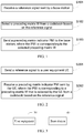
- FIG. 1 is a schematic flowchart of a method for feeding back channel state information according to an embodiment of the present invention
- an execution body of the method may be a user equipment (User Equipment, UE) of an LTE system, for example, may be a user equipment (User Equipment, UE), a mobile station (Mobile Station, MS), or a relay (Relay) (hereinafter referred to as a UE).
- UE User Equipment
- UE User Equipment
- UE User Equipment
- MS Mobile Station
- Relay relay
- step S101 mainly includes step S101, step S102, and step S103.
- Step S101 Receive a reference signal sent by a base station.
- the reference signal sent by the base station may include a channel state information reference signal (Channel State Information Reference Signal, CSI RS), a demodulation reference signal (DeModulation RS, DM RS), a cell-specific reference signal (Cell-specific RS, CRS), or the like.
- the user equipment may obtain the reference signal by receiving an eNB notification, for example, by receiving radio resource control (Radio Resource Control, RRC) signaling or downlink control information (Down Control Information, DCI); or the user equipment obtains resource configuration of the reference signal based on a cell identity ID and then obtains the reference signal from a corresponding resource or subframe.
- RRC Radio Resource Control
- DCI Down Control Information
- the foregoing reference signal is corresponding to an antenna port; the reference signal may be corresponding to a physical antenna or an antenna array element, or may be corresponding to a virtual antenna, where the virtual antenna is a weighted combination of a physical antenna or an antenna array element.
- values of phases ⁇ and ⁇ may be flexibly selected according to a requirement of quantization precision.
- the foregoing structure divides antenna ports into two groups; a vector v may match channel characteristics corresponding to each antenna group of the two groups, and a phase between the two antenna port groups may be expressed by ⁇ .
- the foregoing structure may match actually deployed antenna configuration, for example, configuration of a four-port dual-polarized antenna or a uniform linear array antenna. Phases ⁇ and ⁇ are flexibly selected, which cannot only further improve quantization precision as required, but also achieve balance between overheads and the quantization precision.
- Column vectors of the precoding matrix W are orthogonal to each other, which further reduces inter-layer interference, thereby improving a transmission rate and spectral efficiency of a system.
- a codebook in this embodiment of the present invention may be a codebook subset.
- the codebook subset may be predefined; the codebook subset may be reported by a user equipment to a base station (eNB), and then the base station (eNB) determines the codebook subset based on reporting of the user equipment and notifies the user equipment of the determined codebook subset; or the codebook subset may be a codebook subset determined and reported by a user equipment, for example, a recently reported codebook subset.
- the selecting a precoding matrix from a codebook based on the reference signal may include: acquiring, by a UE, a channel estimation value based on the reference signal; and selecting, by the UE, a precoding matrix from a codebook based on the channel estimation value.
- this embodiment of the present invention sets no limitation on a specific manner of selecting a precoding matrix.
- a precoding matrix is selected from the codebook according to a predefined criterion, such as a criterion of channel capacity or throughput maximization, or a criterion of chordal distance minimization. Selecting a precoding matrix based on a predefined criterion is an existing technology, and details are not described herein again.
- the foregoing precoding matrix W may match actually deployed antenna configuration.
- a granularity of a value of ⁇ is ⁇ 16 , which may achieve more precise spatial quantization, and therefore feedback precision of CSI can be improved.
- the precoding matrix W is at least one matrix in the following matrix set: 1 8 1 1 1 e j ⁇ e j ⁇ 1 ⁇ 1 e j ⁇ ⁇ e j ⁇ , 1 8 1 1 1 e j ⁇ e j ⁇ j ⁇ j e j ⁇ ⁇ j e j ⁇ or 1 8 1 1 e j ⁇ e j ⁇ + ⁇ 1 ⁇ 1 e j ⁇ ⁇ e j ⁇ + ⁇ , 1 8 1 1 e j ⁇ e j ⁇ + ⁇ j ⁇ j j e j ⁇ ⁇ e j ⁇ + ⁇
- ⁇ ⁇ 16 2 i 1 + ⁇ i 2 / 4 ⁇
- i 1 0,...,15
- i 2 0,...,15
- ⁇ ⁇ 16 , ⁇ 8 , ...
- ⁇ i 2 /4 ⁇ indicates that its value is the greatest integer not greater
- the foregoing precoding matrix W may match actually deployed antenna configuration. Because a granularity of a value of ⁇ is ⁇ 16 , more precise spatial quantization is achieved, and feedback precision of CSI can be improved. In addition, two columns of the precoding matrix W are orthogonal to each other, which can reduce inter-layer interference.
- the precoding matrix W is at least one matrix in the following matrix set: 1 12 1 1 1 1 e j ⁇ e j ⁇ ⁇ e j ⁇ 1 ⁇ 1 ⁇ 1 e j ⁇ ⁇ e j ⁇ e j ⁇ , 1 12 1 1 1 1 ⁇ e j ⁇ e j ⁇ ⁇ e j ⁇ 1 ⁇ 1 ⁇ 1 ⁇ e j ⁇ ⁇ e j ⁇ e j ⁇ , 1 12 1 1 1 1 e j ⁇ ⁇ e j ⁇ ⁇ e j ⁇ 1 1 ⁇ 1 e j ⁇ ⁇ e j ⁇ e j ⁇ , 1 12 1 1 1 1 ⁇ e j ⁇ e j ⁇ e j ⁇ e j ⁇ , 1 1 1 1 ⁇ e j ⁇ e j ⁇ e j ⁇ , 1 1 1 1 ⁇ e j ⁇ e j ⁇ e j ⁇ , 1 1 1 1 ⁇ e j ⁇
- the foregoing precoding matrix W may match actually deployed antenna configuration. Because a granularity of a value of ⁇ is ⁇ 16 , more precise spatial quantization is achieved, and feedback precision of CSI can be improved. In addition, two columns of the precoding matrix W are orthogonal to each other, which can reduce inter-layer interference.
- the precoding matrix W is at least one matrix in the following matrix set: 1 4 1 1 1 1 1 1 e j ⁇ ⁇ e j ⁇ e j ⁇ ⁇ e j ⁇ 1 1 ⁇ 1 ⁇ 1 e j ⁇ ⁇ e j ⁇ ⁇ e j ⁇ e j ⁇ , 1 4 1 1 1 1 1 e j ⁇ ⁇ e j ⁇ e j ⁇ ⁇ e j ⁇ j ⁇ j ⁇ j , 1 4 1 1 1 1 1 1 e j ⁇ ⁇ e j ⁇ ⁇ e j ⁇ ⁇ e j ⁇ 1 ⁇ 1 1 ⁇ 1 e j ⁇ ⁇ e j ⁇ ⁇ e j ⁇ e j ⁇ e j ⁇ or 1 4 1 1 1 1 1 1 e j ⁇ e j ⁇ ⁇ e j ⁇ ⁇ e j ⁇ ⁇ e j ⁇ 1 ⁇ 1 1 ⁇ 1 e j ⁇ ⁇ e j ⁇
- the foregoing precoding matrix W may match actually deployed antenna configuration. Because a granularity of a value of ⁇ is ⁇ 4 , more precise spatial quantization is achieved, and feedback precision of CSI can be improved. In addition, two columns of the precoding matrix W are orthogonal to each other, which can reduce inter-layer interference.
- Step S103 Send a precoding matrix indicator PMI to the base station, where the PMI is corresponding to the selected precoding matrix W.
- the index values i 1 and i 2 can uniquely determine a precoding matrix W
- a precoding matrix indicator PMI is sent to the base station and the PMI is corresponding to the selected precoding matrix
- a first precoding matrix indicator PMIi and a first precoding matrix indicator PMI 2 may be sent to the base station, and are respectively corresponding to the index values i 1 and i 2 that are associated with the selected precoding matrix.
- the base station may obtain, according to the first precoding matrix indicator PMI 1 and the first precoding matrix indicator PMI 2 , a precoding matrix selected by a UE from the codebook.
- a precoding matrix indicator PMI 1 and a precoding matrix indicator PMI 2 are respectively used to indicate corresponding precoding matrix indicators indicated by i 1 and i 2 .
- the PMI 1 and the PMI 2 have different time domain or frequency domain granularities, or are obtained based on different subframe periods or sub-band sizes.
- the precoding matrix indicator PMI 1 and the precoding matrix indicator PMI 2 respectively indicate channel characteristics with different periods or bandwidth, or are obtained based on different subframe periods or sub-band sizes. Further, the precoding matrix indicator PMI 1 and the precoding matrix indicator PMI 2 are sent to the base station in different time periods.
- the precoding matrix indicator PMI When a precoding matrix indicator PMI is sent to a base station, the precoding matrix indicator PMI may be sent to the base station by a user equipment through a physical uplink control channel (Physical Uplink Control Channel, PUCCH) or a physical uplink shared channel (Physical Uplink Shared Channel, PUSCH).
- PUCCH Physical Uplink Control Channel
- PUSCH Physical Uplink Shared Channel
- the precoding matrix W in this embodiment of the present invention may be a precoding matrix obtained after row or column displacement. For example, different antenna numbers correspondingly lead to row displacement of the precoding matrix.
- a user equipment may select a precoding matrix from a codebook based on a received reference signal, and send a precoding matrix indicator corresponding to the selected precoding matrix to the base station.
- the foregoing codebook structure may match actually deployed antenna configuration, for example, configuration of a four-port dual-polarized antenna or a uniform linear array antenna; phases ⁇ and ⁇ are flexibly selected, which cannot only further improve quantization precision as required, but also achieve balance between overheads and the quantization precision.
- column vectors of the precoding matrix W are orthogonal to each other, which further reduces inter-layer interference.
- the foregoing embodiment describes in detail a method for feeding back channel state information according to the embodiment of the present invention from a perspective of a UE; with reference to FIG. 2 , the following describes a method for feeding back channel state information according to an embodiment of the present invention from a perspective of a base station.
- FIG. 2 is a method for feeding back channel state information according to another embodiment of the present invention.
- the method in FIG. 2 is implemented by a base station, which, for example, may be a node B (NodeB), an access point (Access Point, AP), a transmission point (Transmission Point, TP), an evolved node B (Evolved Node B, eNB), or a relay (Relay).
- NodeB node B
- AP access point
- TP Transmission Point
- eNB evolved node B
- Relay relay
- step S201 mainly includes step S201 and step S202.
- step S202 mainly includes step S201 and step S202. Detailed description is as follows:
- Step S201 Send a reference signal to a user equipment UE.
- the reference signal may include a CSI RS, a DM RS, a CRS, or the like.
- the base station may instruct the UE to receive the reference signal through higher layer signaling such as RRC signaling or downlink control information DCI; or the base station sends the reference signal over a resource or a subframe of a corresponding reference signal based on a cell identity ID.
- This embodiment of the present invention sets no limitation on a specific manner of sending a reference signal.
- values of phases ⁇ and ⁇ may be flexibly selected according to a requirement of quantization precision.
- the foregoing structure divides antenna ports into two groups; a vector v may match channel characteristics corresponding to each antenna group of the two groups, and a phase between the two antenna port groups may be expressed by ⁇ .
- the foregoing matrix structure may match actually deployed antenna configuration, for example, configuration of a four-port dual-polarized antenna or a uniform linear array antenna.
- Phases ⁇ and ⁇ are flexibly selected, which cannot only further improve quantization precision as required, but also achieve balance between overheads and the quantization precision.
- Column vectors of the precoding matrix W are orthogonal to each other, which further reduces inter-layer interference, thereby improving a transmission rate and spectral efficiency of a system.
- the base station may obtain, according to the PMI, the precoding matrix selected by the UE from the codebook.
- the precoding matrix indicator PMI may include two indexes, that is, a first precoding matrix indicator PMI 1 and a first precoding matrix indicator PMI 2 , where the PMI 1 and the PMI 2 are respectively corresponding to index values i 1 and i 2 that are associated with the selected precoding matrix.
- the base station may obtain, according to the PMI 1 and the PMI 2 , the precoding matrix selected by the UE from the codebook.
- the PMI may be received by a base station through a PUCCH or a PUSCH.
- the precoding matrix W in this embodiment of the present invention may be a precoding matrix obtained after row or column displacement. For example, different antenna numbers correspondingly lead to row displacement of the precoding matrix.
- a base station sends a reference signal and receives a precoding matrix indicator PMI sent by a UE, where the PMI is corresponding to a precoding matrix that is selected by the UE from a codebook based on the reference signal.
- the foregoing codebook structure may match actually deployed antenna configuration, for example, configuration of a four-port dual-polarized antenna or a uniform linear array antenna; phases ⁇ and ⁇ are flexibly selected, which cannot only further improve quantization precision as required, but also achieve balance between overheads and the quantization precision.
- column vectors of the precoding matrix W are orthogonal to each other, which further reduces inter-layer interference.
- FIG. 3 is a schematic diagram of structural composition of a system for feeding back channel state information according to an embodiment of the present invention.
- the system according to this embodiment of the present invention includes a user equipment 30 and a base station 40.
- a structure of the user equipment 30 is shown in FIG. 4
- a structure of the base station 40 is shown in FIG. 5 .
- FIG. 4 is a schematic structural diagram of the user equipment 30 according to the embodiment of the present invention, and the user equipment 30 includes a receiving module 301, a selecting module 302, and a sending module 303, where the receiving module 301 may be implemented by a receiver in the user equipment 30 or a software module/unit or a hardware module/unit of the receiver of the user equipment 30, the selecting module 302 may be implemented by a processor in the user equipment 30 or a software module/unit or a hardware module/unit of the processor of the user equipment 30, and the sending module 303 may be implemented by a transmitter in the user equipment 30 or a software module/unit or a hardware module/unit of the transmitter of the user equipment 30.
- the receiving module 301 may be implemented by a receiver in the user equipment 30 or a software module/unit or a hardware module/unit of the receiver of the user equipment 30
- the selecting module 302 may be implemented by a processor in the user equipment 30 or a software module/unit or a hardware module/unit of the processor of the user equipment 30
- the receiving module 301 is configured to receive a reference signal sent by a base station.
- the reference signal sent by the base station may include a channel state information reference signal (Channel State Information Reference Signal, CSI RS), a demodulation reference signal (DeModulation RS, DM RS), a cell-specific reference signal (Cell-specific RS, CRS), or the like.
- the user equipment may obtain the reference signal by receiving an eNB notification, for example, by receiving radio resource control (Radio Resource Control, RRC) signaling or downlink control information (Down Control Information, DCI); or the user equipment obtains resource configuration of the reference signal based on a cell identity ID and then obtains the reference signal from a corresponding resource or subframe.
- RRC Radio Resource Control
- DCI Down Control Information
- the foregoing reference signal is corresponding to an antenna port; the reference signal may be corresponding to a physical antenna or an antenna array element, or may be corresponding to a virtual antenna, where the virtual antenna is a weighted combination of a physical antenna or an antenna array element.
- values of phases ⁇ and ⁇ may be flexibly selected according to a requirement of quantization precision.
- the foregoing structure divides antenna ports into two groups; a vector v may match channel characteristics corresponding to each antenna group of the two groups, and a phase between the two antenna port groups may be expressed by ⁇ .
- the foregoing structure may match actually deployed antenna configuration, for example, configuration of a four-port dual-polarized antenna or a uniform linear array antenna. Phases ⁇ and ⁇ are flexibly selected, which cannot only further improve quantization precision as required, but also achieve balance between overheads and the quantization precision.
- Column vectors of the precoding matrix W are orthogonal to each other, which further reduces inter-layer interference, thereby improving a transmission rate and spectral efficiency of a system.
- the foregoing codebook structure may match actually deployed antenna configuration, for example, configuration of a four-port dual-polarized antenna or a uniform linear array antenna; phases ⁇ and ⁇ are flexibly selected, which cannot only further improve quantization precision as required, but also achieve balance between overheads and the quantization precision.
- column vectors of the precoding matrix W are orthogonal to each other, which further reduces inter-layer interference.
- the selecting module 302 shown in FIG. 4 may be specifically configured to acquire a channel estimation value based on the reference signal, and select a precoding matrix from a codebook according to the channel estimation value.
- this embodiment of the present invention sets no limitation on a specific manner of selecting a precoding matrix.
- a precoding matrix is selected from the codebook according to a predefined criterion, such as a criterion of channel capacity or throughput maximization, or a criterion of chordal distance minimization. Selecting a precoding matrix based on a predefined criterion is an existing technology, and details are not described herein again.
- the foregoing matrix structure may match actually deployed antenna configuration, for example, configuration of a four-port dual-polarized antenna or a uniform linear array antenna.
- Phases ⁇ and ⁇ are flexibly selected, which cannot only further improve quantization precision as required, but also achieve balance between overheads and the quantization precision.
- Column vectors of the precoding matrix W are orthogonal to each other, which further reduces inter-layer interference, thereby improving a transmission rate and spectral efficiency of a system.
- the sending module 303 is configured to send a precoding matrix indicator PMI to the base station, where the PMI is corresponding to the precoding matrix W selected by the selecting module 302.
- the user equipment may send the precoding matrix indicator PMI to the base station through a PUCCH or a PUSCH.
- the precoding matrix indicator PMI may include two indexes, that is, a first precoding matrix indicator PMI 1 and a first precoding matrix indicator PMI 2 , where the PMI 1 and the PMI 2 are respectively corresponding to index values i 1 and i 2 that are associated with the selected precoding matrix.
- the base station may obtain, according to the first precoding matrix indicator PMI 1 and the first precoding matrix indicator PMI 2 , the precoding matrix selected by the UE from the codebook.
- the PMI 1 and the PMI 2 have different time domain or frequency domain granularities, or are obtained based on different subframe periods or sub-band sizes.
- the precoding matrix indicator PMI 1 and the precoding matrix indicator PMI 2 respectively indicate channel characteristics with different periods or bandwidth, or are obtained based on different subframe periods or sub-band sizes. Further, the precoding matrix indicator PMI 1 and the precoding matrix indicator PMI 2 are sent to the base station in different time periods.
- the precoding matrix indicator PMI When a precoding matrix indicator PMI is sent to a base station, the precoding matrix indicator PMI may be sent to the base station by a user equipment through a PUCCH or a PUSCH.
- the precoding matrix W in this embodiment of the present invention may be a precoding matrix obtained after row or column displacement. For example, different antenna numbers correspondingly lead to row displacement of the precoding matrix.
- the user equipment may select a precoding matrix from a codebook based on a received reference signal, and send a precoding matrix indicator corresponding to the selected precoding matrix to the base station.
- the foregoing codebook structure may match actually deployed antenna configuration, for example, configuration of a four-port dual-polarized antenna or a uniform linear array antenna; phases ⁇ and ⁇ are flexibly selected, which cannot only further improve quantization precision as required, but also achieve balance between overheads and the quantization precision.
- column vectors of the precoding matrix W are orthogonal to each other, which further reduces inter-layer interference.
- division of functional modules is merely used as an example, and the foregoing functions may be allocated to different functional modules according to an actual requirement, for example, according to a corresponding hardware configuration requirement or for ease of software implementation; that is, an internal structure of the user equipment is divided into different functional modules, to complete all or some of the functions described above.
- corresponding functional modules in this embodiment may be implemented by corresponding hardware, or may be implemented by corresponding hardware by implementing corresponding software.
- the foregoing receiving module may be hardware that has a function of implementing the foregoing receiving a reference signal sent by a base station, such as a receiver, or may be a universal processor or another hardware device that can execute a corresponding computer program to complete the foregoing functions.
- the foregoing selecting module may be hardware that has a function of executing the foregoing selecting a precoding matrix W from a codebook based on a reference signal received by the receiving module (or receiver), such as a precoding matrix determiner, or may be a universal processor or another hardware device that can execute a corresponding computer program to complete the foregoing functions. (The principle of the foregoing description may be applicable to each embodiment provided in this specification.)
- FIG. 5 is a schematic structural diagram of a base station according to an embodiment of the present invention.
- the base station includes a second sending module 401 and a second receiving module 402, where the second sending module 401 may be implemented by a transmitter in a base station 40 or a software module/unit or a hardware module/unit of the transmitter in the base station 40; the second receiving module 402 may be implemented by a receiver in the base station 40 or a software module/unit or a hardware module/unit of the receiver in the base station 40; or the second sending module 401 and the second receiving module 402 may be implemented by a processor in the base station 40 or a software module/unit or a hardware module/unit of the processor in the base station 40.
- the second sending module 401 is configured to send a reference signal to a user equipment UE.
- the reference signal may include a CSI RS, a DM RS, a CRS, or the like.
- the base station may instruct the UE to receive the reference signal through higher layer signaling such as RRC signaling or downlink control information DCI; or the base station sends the reference signal over a resource or a subframe of a corresponding reference signal based on a cell identity ID.
- This embodiment of the present invention sets no limitation on a specific manner of sending a reference signal.
- the foregoing reference signal is corresponding to an antenna port; the reference signal may be corresponding to a physical antenna or an antenna array element, or may be corresponding to a virtual antenna, where the virtual antenna is a weighted combination of a physical antenna or an antenna array element.
- values of phases ⁇ and ⁇ may be flexibly selected according to a requirement of quantization precision.
- the foregoing structure divides antenna ports into two groups; a vector v may match channel characteristics corresponding to each antenna group of the two groups, and a phase between the two antenna port groups may be expressed by ⁇ .
- the foregoing structure may match actually deployed antenna configuration, for example, configuration of a four-port dual-polarized antenna or a uniform linear array antenna. Phases ⁇ and ⁇ are flexibly selected, which cannot only further improve quantization precision as required, but also achieve balance between overheads and the quantization precision.
- Column vectors of the precoding matrix W are orthogonal to each other, which further reduces inter-layer interference, thereby improving a transmission rate and spectral efficiency of a system.
- the foregoing matrix structure may match actually deployed antenna configuration, for example, configuration of a four-port dual-polarized antenna or a uniform linear array antenna.
- Phases ⁇ and ⁇ are flexibly selected, which cannot only further improve quantization precision as required, but also achieve balance between overheads and the quantization precision.
- Column vectors of the precoding matrix W are orthogonal to each other, which further reduces inter-layer interference, thereby improving a transmission rate and spectral efficiency of a system.
- the foregoing matrix structure may match actually deployed antenna configuration, for example, configuration of a four-port dual-polarized antenna or a uniform linear array antenna.
- Phases ⁇ and ⁇ are flexibly selected, which cannot only further improve quantization precision as required, but also achieve balance between overheads and the quantization precision.
- Column vectors of the precoding matrix W are orthogonal to each other, which further reduces inter-layer interference, thereby improving a transmission rate and spectral efficiency of a system.
- the base station may obtain, according to the PMI, the precoding matrix selected by the UE from the codebook.
- the precoding matrix indicator PMI may include two indexes, that is, a first precoding matrix indicator PMI 1 and a first precoding matrix indicator PMI 2 , where the PMI 1 and the PMI 2 are respectively corresponding to index values i 1 and i 2 that are associated with the selected precoding matrix.
- the base station may obtain, according to the PMI 1 and the PMI 2 , the precoding matrix selected by the UE from the codebook.
- the PMI may be received by a base station through a PUCCH or a PUSCH.
- the precoding matrix W in this embodiment of the present invention may be a precoding matrix obtained after row or column displacement. For example, different antenna numbers correspondingly lead to row displacement of the precoding matrix.
- the base station sends a reference signal and receives a precoding matrix indicator PMI sent by a UE, where the PMI is corresponding to a precoding matrix that is selected by the UE from a codebook based on the reference signal.
- the foregoing codebook structure may match actually deployed antenna configuration, for example, configuration of a four-port dual-polarized antenna or a uniform linear array antenna; phases ⁇ and ⁇ are flexibly selected, which cannot only further improve quantization precision as required, but also achieve balance between overheads and the quantization precision.
- column vectors of the precoding matrix W are orthogonal to each other, which further reduces inter-layer interference.
- An embodiment of the present invention further provides a computer storage medium, where the computer storage medium may store a program, and when the program is executed, the steps illustrated in FIG. 1 or FIG. 2 are performed.
- the program may be stored in a computer readable storage medium.
- the storage medium may include: a read-only memory (Read-Only Memory, ROM), a random access memory (Random Access Memory, RAM), a magnetic disk, or an optical disc.
Landscapes
- Engineering & Computer Science (AREA)
- Computer Networks & Wireless Communication (AREA)
- Signal Processing (AREA)
- Physics & Mathematics (AREA)
- Mathematical Physics (AREA)
- Mobile Radio Communication Systems (AREA)
- Radio Transmission System (AREA)
Priority Applications (3)
| Application Number | Priority Date | Filing Date | Title |
|---|---|---|---|
| EP20214431.7A EP3855638B1 (de) | 2012-12-27 | 2012-12-27 | Verfahren zur rückkopplung von kanalstatusinformationen, benutzergerät und basisstation |
| EP19162446.9A EP3588801B1 (de) | 2012-12-27 | 2012-12-27 | Verfahren zur rückkopplung von kanalstatusinformationen, benutzergerät und basisstation |
| EP22197640.0A EP4170919A1 (de) | 2012-12-27 | 2012-12-27 | Verfahren zur rückkopplung von kanalstatusinformationen, benutzergerät und basisstation |
Applications Claiming Priority (4)
| Application Number | Priority Date | Filing Date | Title |
|---|---|---|---|
| PCT/CN2012/087699 WO2014101055A1 (zh) | 2012-12-27 | 2012-12-27 | 信道状态信息反馈的方法以及一种用户设备和基站 |
| EP16195533.1A EP3197070B1 (de) | 2012-12-27 | 2012-12-27 | Verfahren zur rückkopplung von kanalstatusinformationen, benutzergerät und basisstation |
| EP12891145.0A EP2947787B1 (de) | 2012-12-27 | 2012-12-27 | Verfahren zur rückkopplung von kanalstatusinformationen, benutzergerät und basisstation |
| EP19162446.9A EP3588801B1 (de) | 2012-12-27 | 2012-12-27 | Verfahren zur rückkopplung von kanalstatusinformationen, benutzergerät und basisstation |
Related Parent Applications (3)
| Application Number | Title | Priority Date | Filing Date |
|---|---|---|---|
| EP12891145.0A Division EP2947787B1 (de) | 2012-12-27 | 2012-12-27 | Verfahren zur rückkopplung von kanalstatusinformationen, benutzergerät und basisstation |
| EP16195533.1A Division EP3197070B1 (de) | 2012-12-27 | 2012-12-27 | Verfahren zur rückkopplung von kanalstatusinformationen, benutzergerät und basisstation |
| EP16195533.1A Division-Into EP3197070B1 (de) | 2012-12-27 | 2012-12-27 | Verfahren zur rückkopplung von kanalstatusinformationen, benutzergerät und basisstation |
Related Child Applications (3)
| Application Number | Title | Priority Date | Filing Date |
|---|---|---|---|
| EP20214431.7A Division EP3855638B1 (de) | 2012-12-27 | 2012-12-27 | Verfahren zur rückkopplung von kanalstatusinformationen, benutzergerät und basisstation |
| EP20214431.7A Division-Into EP3855638B1 (de) | 2012-12-27 | 2012-12-27 | Verfahren zur rückkopplung von kanalstatusinformationen, benutzergerät und basisstation |
| EP22197640.0A Division EP4170919A1 (de) | 2012-12-27 | 2012-12-27 | Verfahren zur rückkopplung von kanalstatusinformationen, benutzergerät und basisstation |
Publications (2)
| Publication Number | Publication Date |
|---|---|
| EP3588801A1 true EP3588801A1 (de) | 2020-01-01 |
| EP3588801B1 EP3588801B1 (de) | 2021-02-24 |
Family
ID=51019704
Family Applications (5)
| Application Number | Title | Priority Date | Filing Date |
|---|---|---|---|
| EP22197640.0A Pending EP4170919A1 (de) | 2012-12-27 | 2012-12-27 | Verfahren zur rückkopplung von kanalstatusinformationen, benutzergerät und basisstation |
| EP16195533.1A Active EP3197070B1 (de) | 2012-12-27 | 2012-12-27 | Verfahren zur rückkopplung von kanalstatusinformationen, benutzergerät und basisstation |
| EP12891145.0A Not-in-force EP2947787B1 (de) | 2012-12-27 | 2012-12-27 | Verfahren zur rückkopplung von kanalstatusinformationen, benutzergerät und basisstation |
| EP20214431.7A Active EP3855638B1 (de) | 2012-12-27 | 2012-12-27 | Verfahren zur rückkopplung von kanalstatusinformationen, benutzergerät und basisstation |
| EP19162446.9A Active EP3588801B1 (de) | 2012-12-27 | 2012-12-27 | Verfahren zur rückkopplung von kanalstatusinformationen, benutzergerät und basisstation |
Family Applications Before (4)
| Application Number | Title | Priority Date | Filing Date |
|---|---|---|---|
| EP22197640.0A Pending EP4170919A1 (de) | 2012-12-27 | 2012-12-27 | Verfahren zur rückkopplung von kanalstatusinformationen, benutzergerät und basisstation |
| EP16195533.1A Active EP3197070B1 (de) | 2012-12-27 | 2012-12-27 | Verfahren zur rückkopplung von kanalstatusinformationen, benutzergerät und basisstation |
| EP12891145.0A Not-in-force EP2947787B1 (de) | 2012-12-27 | 2012-12-27 | Verfahren zur rückkopplung von kanalstatusinformationen, benutzergerät und basisstation |
| EP20214431.7A Active EP3855638B1 (de) | 2012-12-27 | 2012-12-27 | Verfahren zur rückkopplung von kanalstatusinformationen, benutzergerät und basisstation |
Country Status (11)
| Country | Link |
|---|---|
| US (7) | US9438328B2 (de) |
| EP (5) | EP4170919A1 (de) |
| JP (1) | JP6118423B2 (de) |
| CN (2) | CN107689823B (de) |
| BR (1) | BR112015015418B1 (de) |
| MX (1) | MX344041B (de) |
| MY (1) | MY161041A (de) |
| RU (1) | RU2618508C2 (de) |
| SG (1) | SG11201505013UA (de) |
| WO (1) | WO2014101055A1 (de) |
| ZA (1) | ZA201504716B (de) |
Families Citing this family (21)
| Publication number | Priority date | Publication date | Assignee | Title |
|---|---|---|---|---|
| MY161041A (en) | 2012-12-27 | 2017-04-14 | Huawei Tech Co Ltd | Method for feeding back channel state information, user equipment, and base station |
| CN104065448B (zh) * | 2013-03-22 | 2017-11-14 | 电信科学技术研究院 | 一种确定预编码矩阵的方法、系统和设备 |
| JP5950029B2 (ja) * | 2013-04-04 | 2016-07-13 | 富士通株式会社 | 移動局、基地局、及び通信制御方法 |
| US11095342B2 (en) | 2015-10-04 | 2021-08-17 | Lg Electronics Inc. | Method for transmitting and receiving channel state information in wireless communication system, and apparatus therefor |
| CN106685598B (zh) * | 2015-11-06 | 2019-06-14 | 电信科学技术研究院 | 一种信道状态信息csi反馈方法、终端及基站 |
| CN106953672B (zh) * | 2016-01-07 | 2020-04-14 | 中兴通讯股份有限公司 | 一种多天线系统中信道信息反馈的方法及终端 |
| CN107404342A (zh) * | 2016-05-19 | 2017-11-28 | 北京信威通信技术股份有限公司 | 一种下行多天线预编码方法及系统 |
| CN107733494B (zh) * | 2016-08-12 | 2021-06-29 | 大唐移动通信设备有限公司 | 一种预编码方法、信道状态信息确定方法及装置 |
| JP2020506646A (ja) * | 2017-01-25 | 2020-02-27 | 華為技術有限公司Huawei Technologies Co.,Ltd. | チャネル状態情報送信方法、アクセスネットワークデバイス、及び、端末デバイス |
| CN108631847B (zh) | 2017-03-24 | 2021-06-01 | 华为技术有限公司 | 传输信道状态信息的方法、终端设备和网络设备 |
| WO2018231141A1 (en) | 2017-06-16 | 2018-12-20 | Telefonaktiebolaget Lm Ericsson (Publ) | Multi-resource uplink sounding and antenna subset transmission |
| US10879973B2 (en) * | 2017-10-02 | 2020-12-29 | Lenovo (Singapore) Pte. Ltd. | Method and apparatus for using a determined compression matrix to form a set of composite beams |
| CN111837432B (zh) * | 2018-07-03 | 2022-02-01 | Oppo广东移动通信有限公司 | 确定信道状态信息的方法、终端设备及存储介质 |
| CN110535512B (zh) * | 2018-10-31 | 2023-06-30 | 中兴通讯股份有限公司 | 一种报告天线端口加权矢量的方法、装置和系统 |
| CN111436080B (zh) * | 2019-01-11 | 2023-05-05 | 大唐移动通信设备有限公司 | 一种信息发送方法、终端设备及网络设备 |
| GB202008299D0 (en) * | 2020-06-02 | 2020-07-15 | Imagination Tech Ltd | Manipulation of data in a memory |
| EP4274112A4 (de) * | 2021-01-31 | 2024-02-28 | Huawei Technologies Co., Ltd. | Verfahren zur rückkopplung von kanalstatusinformationen und kommunikationsvorrichtung |
| CN113364494B (zh) * | 2021-05-06 | 2022-08-16 | 西安交通大学 | 一种针对硬件失真的irs辅助miso系统性能优化方法 |
| US11909472B2 (en) * | 2021-11-16 | 2024-02-20 | Samsung Electronics Co., Ltd | Method and apparatus for selection of linear combination coefficients for precoding in frequency-selective channels |
| CN118740215A (zh) * | 2023-03-30 | 2024-10-01 | 上海朗帛通信技术有限公司 | 用于无线通信的方法和装置 |
| WO2024242380A1 (ko) * | 2023-05-19 | 2024-11-28 | 삼성전자 주식회사 | 무선 통신 시스템에서 pmi를 결정하는 방법 및 장치 |
Family Cites Families (31)
| Publication number | Priority date | Publication date | Assignee | Title |
|---|---|---|---|---|
| KR20080040543A (ko) | 2006-11-02 | 2008-05-08 | 엘지전자 주식회사 | 위상천이 기반 프리코딩을 이용한 데이터 전송 방법 및이를 지원하는 송수신기 |
| US8259824B2 (en) | 2007-05-23 | 2012-09-04 | Texas Instruments Incorporated | Nested precoding codebook structures for MIMO systems |
| US8798183B2 (en) * | 2007-08-13 | 2014-08-05 | Qualcomm Incorporated | Feedback and rate adaptation for MIMO transmission in a time division duplexed (TDD) communication system |
| US7680621B2 (en) | 2007-08-15 | 2010-03-16 | Keithley Instruments, Inc. | Test instrument network |
| CN101394216B (zh) * | 2007-09-18 | 2013-01-16 | 中兴通讯股份有限公司 | 一种基于码本方式的预编码方法和码本构建方法 |
| CN101867463B (zh) * | 2007-09-18 | 2012-12-19 | 中兴通讯股份有限公司 | 一种基于码本方式的预编码方法和码本构建方法 |
| KR100912226B1 (ko) * | 2008-06-27 | 2009-08-14 | 삼성전자주식회사 | 다중 입출력 시스템을 위한 코드북 설계 방법 및 상기 코드북의 사용 방법 |
| KR101027237B1 (ko) * | 2008-07-30 | 2011-04-06 | 엘지전자 주식회사 | 다중안테나 시스템에서 데이터 전송방법 |
| KR20100013251A (ko) * | 2008-07-30 | 2010-02-09 | 엘지전자 주식회사 | 다중안테나 시스템에서 데이터 전송방법 |
| US8451932B2 (en) * | 2009-02-23 | 2013-05-28 | Texas Instruments Incorporated | Precoding codebook design for single user MIMO |
| WO2010123297A2 (ko) * | 2009-04-22 | 2010-10-28 | 엘지전자 주식회사 | 무선 통신 시스템에서 다중 셀 협력 통신을 위한 프리코딩 코드북을 이용하여 피드백 정보 및 데이터를 전송하는 방법 |
| US8750205B2 (en) * | 2009-08-07 | 2014-06-10 | Texas Instruments Incorporated | Multiple rank CQI feedback for cellular networks |
| CN102035625A (zh) * | 2009-09-29 | 2011-04-27 | 松下电器产业株式会社 | 优化通信系统的预编码器的方法、基站和终端 |
| KR20110083531A (ko) | 2010-01-12 | 2011-07-20 | 주식회사 팬택 | 채널정보 피드백 장치와 그 방법, 기지국, 그 기지국의 통신방법 |
| JP5258002B2 (ja) | 2010-02-10 | 2013-08-07 | マーベル ワールド トレード リミテッド | Mimo通信システムにおける装置、移動通信端末、チップセット、およびその方法 |
| KR101871707B1 (ko) * | 2010-04-02 | 2018-06-27 | 엘지전자 주식회사 | 무선통신 시스템에서 채널상태정보 피드백 하는 단말 장치 및 그 방법 |
| JP5785605B2 (ja) | 2010-04-08 | 2015-09-30 | エルジー エレクトロニクス インコーポレイティド | 多重アンテナ支援無線通信システムにおいてコードブックを用いた信号伝送方法及び装置 |
| KR101817724B1 (ko) * | 2010-04-30 | 2018-02-21 | 삼성전자주식회사 | 각 리포팅 모드에 대응하는 코드북을 사용하는 다중 입출력 통신 시스템 |
| US8848817B2 (en) * | 2010-04-30 | 2014-09-30 | Texas Instruments Incorporated | Transmission modes and signaling for uplink MIMO support or single TB dual-layer transmission in LTE uplink |
| US8630311B2 (en) * | 2010-05-10 | 2014-01-14 | Futurewei Technologies, Inc. | System and method for reporting quantized feedback information for adaptive codebooks |
| CN101902312B (zh) * | 2010-06-21 | 2016-02-10 | 中兴通讯股份有限公司 | 一种多精度的信道信息获取方法及系统 |
| EP2590338B1 (de) * | 2010-07-02 | 2020-03-11 | LG Electronics Inc. | Verfahren und vorrichtung zur signalübertragung mithilfe von codebüchern in einem drahtlosen kommunikationssystem mit unterstützung mehrerer antennen |
| US8537658B2 (en) * | 2010-08-16 | 2013-09-17 | Motorola Mobility Llc | Method of codebook design and precoder feedback in wireless communication systems |
| KR101875609B1 (ko) * | 2010-09-26 | 2018-08-02 | 엘지전자 주식회사 | 다중 안테나 지원 무선 통신 시스템에서 효율적인 피드백 방법 및 장치 |
| US8711907B2 (en) * | 2010-10-01 | 2014-04-29 | Intel Corporation | PMI feedback with codebook interpolation |
| KR101891114B1 (ko) * | 2010-11-02 | 2018-08-23 | 엘지전자 주식회사 | 보간을 이용한 프리코딩 행렬 지시자 피드백 방법 및 장치 |
| US9319118B2 (en) * | 2011-04-29 | 2016-04-19 | Yuan Zhu | Technology for CSI feedback in a MIMO communication system |
| CN107276642B (zh) * | 2011-11-09 | 2021-05-18 | 瑞典爱立信有限公司 | 针对csi-rs资源的集合的csi报告 |
| CN102368698B (zh) * | 2011-11-10 | 2014-04-16 | 电信科学技术研究院 | 一种预编码矩阵指示pmi信息的传输方法及装置 |
| WO2013129985A1 (en) * | 2012-03-02 | 2013-09-06 | Telefonaktiebolaget L M Ericsson (Publ) | Radio base station and method therein for transforming a data transmission signal |
| MY161041A (en) * | 2012-12-27 | 2017-04-14 | Huawei Tech Co Ltd | Method for feeding back channel state information, user equipment, and base station |
-
2012
- 2012-12-27 MY MYPI2015001646A patent/MY161041A/en unknown
- 2012-12-27 EP EP22197640.0A patent/EP4170919A1/de active Pending
- 2012-12-27 CN CN201710943699.9A patent/CN107689823B/zh active Active
- 2012-12-27 EP EP16195533.1A patent/EP3197070B1/de active Active
- 2012-12-27 EP EP12891145.0A patent/EP2947787B1/de not_active Not-in-force
- 2012-12-27 SG SG11201505013UA patent/SG11201505013UA/en unknown
- 2012-12-27 MX MX2015008407A patent/MX344041B/es active IP Right Grant
- 2012-12-27 CN CN201280020417.3A patent/CN104067533B/zh active Active
- 2012-12-27 JP JP2015549920A patent/JP6118423B2/ja active Active
- 2012-12-27 RU RU2015130998A patent/RU2618508C2/ru active
- 2012-12-27 WO PCT/CN2012/087699 patent/WO2014101055A1/zh not_active Ceased
- 2012-12-27 EP EP20214431.7A patent/EP3855638B1/de active Active
- 2012-12-27 BR BR112015015418-2A patent/BR112015015418B1/pt active IP Right Grant
- 2012-12-27 EP EP19162446.9A patent/EP3588801B1/de active Active
-
2015
- 2015-06-29 US US14/753,490 patent/US9438328B2/en active Active
- 2015-06-30 ZA ZA2015/04716A patent/ZA201504716B/en unknown
-
2016
- 2016-08-05 US US15/229,576 patent/US9729222B2/en active Active
-
2017
- 2017-08-03 US US15/668,531 patent/US10230443B2/en active Active
-
2019
- 2019-02-05 US US16/268,284 patent/US10484069B2/en active Active
- 2019-10-11 US US16/599,877 patent/US10715239B2/en active Active
-
2020
- 2020-06-18 US US16/904,999 patent/US11431392B2/en active Active
-
2022
- 2022-07-26 US US17/873,580 patent/US11831379B2/en active Active
Non-Patent Citations (2)
| Title |
|---|
| ERICSSON ET AL: "Design and Evaluation of Precoder Codebooks for CSI Feedback", 3GPP DRAFT; R1-103839_PRECODER_CB_DESIGN, 3RD GENERATION PARTNERSHIP PROJECT (3GPP), MOBILE COMPETENCE CENTRE ; 650, ROUTE DES LUCIOLES ; F-06921 SOPHIA-ANTIPOLIS CEDEX ; FRANCE, vol. RAN WG1, no. Dresden, Germany; 20100628, 24 June 2010 (2010-06-24), XP050449505 * |
| LU WU ET AL: "Codebook Design for LTE-A Downlink System", VEHICULAR TECHNOLOGY CONFERENCE (VTC FALL), 2011 IEEE, IEEE, 5 September 2011 (2011-09-05), pages 1 - 5, XP032029477, ISBN: 978-1-4244-8328-0, DOI: 10.1109/VETECF.2011.6092993 * |
Also Published As
Similar Documents
| Publication | Publication Date | Title |
|---|---|---|
| US11831379B2 (en) | Method for feeding backchannel state information, user equipment, and base station | |
| EP3522384B1 (de) | Verfahren und vorrichtung zur festlegung einer vorcodierungsmatrix | |
| EP2993805B1 (de) | Verfahren und vorrichtung zur übertragung von kanalstatusinformationen in einem drahtlosen kommunikationssystem | |
| US8938020B2 (en) | Method and device for transmitting/receiving a signal by using a code book in a wireless communication system | |
| US20190131008A1 (en) | Methods and Systems for CSI-RS Port Selection for CSI-Reporting | |
| EP2985923B1 (de) | Verfahren zur bestimmung eines vorcodierungsmatrixindikators, benutzervorrichtung und basisstation | |
| EP3444960B1 (de) | Verfahren und vorrichtung zur zweistufigen vorcodierung | |
| EP3910815A1 (de) | Verfahren und vorrichtung für codebuchdesign und -signalisierung | |
| US20250202546A1 (en) | Csi reporting for 5g nr systems | |
| US20160072567A1 (en) | Method and apparatus for transmitting channel state information in wireless communication system | |
| EP2996257B1 (de) | Verfahren und vorrichtung zur übertragung von kanalstatusinformationen in drahtlosen kommunikationssystemen | |
| EP2945300B1 (de) | Verfahren und vorrichtung zum senden und empfangen von signalen anhand eines codebuchs in einem drahtlosen kommunikationssystem |
Legal Events
| Date | Code | Title | Description |
|---|---|---|---|
| PUAI | Public reference made under article 153(3) epc to a published international application that has entered the european phase |
Free format text: ORIGINAL CODE: 0009012 |
|
| STAA | Information on the status of an ep patent application or granted ep patent |
Free format text: STATUS: THE APPLICATION HAS BEEN PUBLISHED |
|
| AC | Divisional application: reference to earlier application |
Ref document number: 2947787 Country of ref document: EP Kind code of ref document: P Ref document number: 3197070 Country of ref document: EP Kind code of ref document: P |
|
| AK | Designated contracting states |
Kind code of ref document: A1 Designated state(s): AL AT BE BG CH CY CZ DE DK EE ES FI FR GB GR HR HU IE IS IT LI LT LU LV MC MK MT NL NO PL PT RO RS SE SI SK SM TR |
|
| STAA | Information on the status of an ep patent application or granted ep patent |
Free format text: STATUS: REQUEST FOR EXAMINATION WAS MADE |
|
| 17P | Request for examination filed |
Effective date: 20200701 |
|
| RBV | Designated contracting states (corrected) |
Designated state(s): AL AT BE BG CH CY CZ DE DK EE ES FI FR GB GR HR HU IE IS IT LI LT LU LV MC MK MT NL NO PL PT RO RS SE SI SK SM TR |
|
| GRAP | Despatch of communication of intention to grant a patent |
Free format text: ORIGINAL CODE: EPIDOSNIGR1 |
|
| STAA | Information on the status of an ep patent application or granted ep patent |
Free format text: STATUS: GRANT OF PATENT IS INTENDED |
|
| INTG | Intention to grant announced |
Effective date: 20200903 |
|
| RAP1 | Party data changed (applicant data changed or rights of an application transferred) |
Owner name: HUAWEI TECHNOLOGIES CO., LTD. |
|
| RIN1 | Information on inventor provided before grant (corrected) |
Inventor name: WANG, JIANGUO Inventor name: ZHOU, YONGXING Inventor name: ZHANG, LEIMING |
|
| GRAS | Grant fee paid |
Free format text: ORIGINAL CODE: EPIDOSNIGR3 |
|
| GRAA | (expected) grant |
Free format text: ORIGINAL CODE: 0009210 |
|
| STAA | Information on the status of an ep patent application or granted ep patent |
Free format text: STATUS: THE PATENT HAS BEEN GRANTED |
|
| AC | Divisional application: reference to earlier application |
Ref document number: 3197070 Country of ref document: EP Kind code of ref document: P Ref document number: 2947787 Country of ref document: EP Kind code of ref document: P |
|
| AK | Designated contracting states |
Kind code of ref document: B1 Designated state(s): AL AT BE BG CH CY CZ DE DK EE ES FI FR GB GR HR HU IE IS IT LI LT LU LV MC MK MT NL NO PL PT RO RS SE SI SK SM TR |
|
| REG | Reference to a national code |
Ref country code: CH Ref legal event code: EP |
|
| REG | Reference to a national code |
Ref country code: AT Ref legal event code: REF Ref document number: 1365806 Country of ref document: AT Kind code of ref document: T Effective date: 20210315 |
|
| REG | Reference to a national code |
Ref country code: IE Ref legal event code: FG4D |
|
| REG | Reference to a national code |
Ref country code: DE Ref legal event code: R096 Ref document number: 602012074585 Country of ref document: DE |
|
| REG | Reference to a national code |
Ref country code: NL Ref legal event code: FP |
|
| REG | Reference to a national code |
Ref country code: LT Ref legal event code: MG9D |
|
| PG25 | Lapsed in a contracting state [announced via postgrant information from national office to epo] |
Ref country code: BG Free format text: LAPSE BECAUSE OF FAILURE TO SUBMIT A TRANSLATION OF THE DESCRIPTION OR TO PAY THE FEE WITHIN THE PRESCRIBED TIME-LIMIT Effective date: 20210524 Ref country code: GR Free format text: LAPSE BECAUSE OF FAILURE TO SUBMIT A TRANSLATION OF THE DESCRIPTION OR TO PAY THE FEE WITHIN THE PRESCRIBED TIME-LIMIT Effective date: 20210525 Ref country code: HR Free format text: LAPSE BECAUSE OF FAILURE TO SUBMIT A TRANSLATION OF THE DESCRIPTION OR TO PAY THE FEE WITHIN THE PRESCRIBED TIME-LIMIT Effective date: 20210224 Ref country code: FI Free format text: LAPSE BECAUSE OF FAILURE TO SUBMIT A TRANSLATION OF THE DESCRIPTION OR TO PAY THE FEE WITHIN THE PRESCRIBED TIME-LIMIT Effective date: 20210224 Ref country code: NO Free format text: LAPSE BECAUSE OF FAILURE TO SUBMIT A TRANSLATION OF THE DESCRIPTION OR TO PAY THE FEE WITHIN THE PRESCRIBED TIME-LIMIT Effective date: 20210524 Ref country code: PT Free format text: LAPSE BECAUSE OF FAILURE TO SUBMIT A TRANSLATION OF THE DESCRIPTION OR TO PAY THE FEE WITHIN THE PRESCRIBED TIME-LIMIT Effective date: 20210624 Ref country code: LT Free format text: LAPSE BECAUSE OF FAILURE TO SUBMIT A TRANSLATION OF THE DESCRIPTION OR TO PAY THE FEE WITHIN THE PRESCRIBED TIME-LIMIT Effective date: 20210224 |
|
| REG | Reference to a national code |
Ref country code: AT Ref legal event code: MK05 Ref document number: 1365806 Country of ref document: AT Kind code of ref document: T Effective date: 20210224 |
|
| PG25 | Lapsed in a contracting state [announced via postgrant information from national office to epo] |
Ref country code: RS Free format text: LAPSE BECAUSE OF FAILURE TO SUBMIT A TRANSLATION OF THE DESCRIPTION OR TO PAY THE FEE WITHIN THE PRESCRIBED TIME-LIMIT Effective date: 20210224 Ref country code: PL Free format text: LAPSE BECAUSE OF FAILURE TO SUBMIT A TRANSLATION OF THE DESCRIPTION OR TO PAY THE FEE WITHIN THE PRESCRIBED TIME-LIMIT Effective date: 20210224 Ref country code: LV Free format text: LAPSE BECAUSE OF FAILURE TO SUBMIT A TRANSLATION OF THE DESCRIPTION OR TO PAY THE FEE WITHIN THE PRESCRIBED TIME-LIMIT Effective date: 20210224 Ref country code: SE Free format text: LAPSE BECAUSE OF FAILURE TO SUBMIT A TRANSLATION OF THE DESCRIPTION OR TO PAY THE FEE WITHIN THE PRESCRIBED TIME-LIMIT Effective date: 20210224 |
|
| PG25 | Lapsed in a contracting state [announced via postgrant information from national office to epo] |
Ref country code: IS Free format text: LAPSE BECAUSE OF FAILURE TO SUBMIT A TRANSLATION OF THE DESCRIPTION OR TO PAY THE FEE WITHIN THE PRESCRIBED TIME-LIMIT Effective date: 20210624 |
|
| PG25 | Lapsed in a contracting state [announced via postgrant information from national office to epo] |
Ref country code: AT Free format text: LAPSE BECAUSE OF FAILURE TO SUBMIT A TRANSLATION OF THE DESCRIPTION OR TO PAY THE FEE WITHIN THE PRESCRIBED TIME-LIMIT Effective date: 20210224 Ref country code: SM Free format text: LAPSE BECAUSE OF FAILURE TO SUBMIT A TRANSLATION OF THE DESCRIPTION OR TO PAY THE FEE WITHIN THE PRESCRIBED TIME-LIMIT Effective date: 20210224 Ref country code: EE Free format text: LAPSE BECAUSE OF FAILURE TO SUBMIT A TRANSLATION OF THE DESCRIPTION OR TO PAY THE FEE WITHIN THE PRESCRIBED TIME-LIMIT Effective date: 20210224 Ref country code: CZ Free format text: LAPSE BECAUSE OF FAILURE TO SUBMIT A TRANSLATION OF THE DESCRIPTION OR TO PAY THE FEE WITHIN THE PRESCRIBED TIME-LIMIT Effective date: 20210224 |
|
| REG | Reference to a national code |
Ref country code: DE Ref legal event code: R097 Ref document number: 602012074585 Country of ref document: DE |
|
| PG25 | Lapsed in a contracting state [announced via postgrant information from national office to epo] |
Ref country code: DK Free format text: LAPSE BECAUSE OF FAILURE TO SUBMIT A TRANSLATION OF THE DESCRIPTION OR TO PAY THE FEE WITHIN THE PRESCRIBED TIME-LIMIT Effective date: 20210224 Ref country code: RO Free format text: LAPSE BECAUSE OF FAILURE TO SUBMIT A TRANSLATION OF THE DESCRIPTION OR TO PAY THE FEE WITHIN THE PRESCRIBED TIME-LIMIT Effective date: 20210224 Ref country code: SK Free format text: LAPSE BECAUSE OF FAILURE TO SUBMIT A TRANSLATION OF THE DESCRIPTION OR TO PAY THE FEE WITHIN THE PRESCRIBED TIME-LIMIT Effective date: 20210224 |
|
| PLBE | No opposition filed within time limit |
Free format text: ORIGINAL CODE: 0009261 |
|
| STAA | Information on the status of an ep patent application or granted ep patent |
Free format text: STATUS: NO OPPOSITION FILED WITHIN TIME LIMIT |
|
| PG25 | Lapsed in a contracting state [announced via postgrant information from national office to epo] |
Ref country code: AL Free format text: LAPSE BECAUSE OF FAILURE TO SUBMIT A TRANSLATION OF THE DESCRIPTION OR TO PAY THE FEE WITHIN THE PRESCRIBED TIME-LIMIT Effective date: 20210224 Ref country code: ES Free format text: LAPSE BECAUSE OF FAILURE TO SUBMIT A TRANSLATION OF THE DESCRIPTION OR TO PAY THE FEE WITHIN THE PRESCRIBED TIME-LIMIT Effective date: 20210224 |
|
| 26N | No opposition filed |
Effective date: 20211125 |
|
| PG25 | Lapsed in a contracting state [announced via postgrant information from national office to epo] |
Ref country code: SI Free format text: LAPSE BECAUSE OF FAILURE TO SUBMIT A TRANSLATION OF THE DESCRIPTION OR TO PAY THE FEE WITHIN THE PRESCRIBED TIME-LIMIT Effective date: 20210224 |
|
| PG25 | Lapsed in a contracting state [announced via postgrant information from national office to epo] |
Ref country code: IT Free format text: LAPSE BECAUSE OF FAILURE TO SUBMIT A TRANSLATION OF THE DESCRIPTION OR TO PAY THE FEE WITHIN THE PRESCRIBED TIME-LIMIT Effective date: 20210224 |
|
| PG25 | Lapsed in a contracting state [announced via postgrant information from national office to epo] |
Ref country code: IS Free format text: LAPSE BECAUSE OF FAILURE TO SUBMIT A TRANSLATION OF THE DESCRIPTION OR TO PAY THE FEE WITHIN THE PRESCRIBED TIME-LIMIT Effective date: 20210624 |
|
| PG25 | Lapsed in a contracting state [announced via postgrant information from national office to epo] |
Ref country code: MC Free format text: LAPSE BECAUSE OF FAILURE TO SUBMIT A TRANSLATION OF THE DESCRIPTION OR TO PAY THE FEE WITHIN THE PRESCRIBED TIME-LIMIT Effective date: 20210224 |
|
| REG | Reference to a national code |
Ref country code: CH Ref legal event code: PL |
|
| REG | Reference to a national code |
Ref country code: BE Ref legal event code: MM Effective date: 20211231 |
|
| PG25 | Lapsed in a contracting state [announced via postgrant information from national office to epo] |
Ref country code: IE Free format text: LAPSE BECAUSE OF NON-PAYMENT OF DUE FEES Effective date: 20211227 Ref country code: LU Free format text: LAPSE BECAUSE OF NON-PAYMENT OF DUE FEES Effective date: 20211227 |
|
| PG25 | Lapsed in a contracting state [announced via postgrant information from national office to epo] |
Ref country code: FR Free format text: LAPSE BECAUSE OF NON-PAYMENT OF DUE FEES Effective date: 20211231 Ref country code: BE Free format text: LAPSE BECAUSE OF NON-PAYMENT OF DUE FEES Effective date: 20211231 |
|
| PG25 | Lapsed in a contracting state [announced via postgrant information from national office to epo] |
Ref country code: LI Free format text: LAPSE BECAUSE OF NON-PAYMENT OF DUE FEES Effective date: 20211231 Ref country code: CH Free format text: LAPSE BECAUSE OF NON-PAYMENT OF DUE FEES Effective date: 20211231 |
|
| P01 | Opt-out of the competence of the unified patent court (upc) registered |
Effective date: 20230514 |
|
| PG25 | Lapsed in a contracting state [announced via postgrant information from national office to epo] |
Ref country code: CY Free format text: LAPSE BECAUSE OF FAILURE TO SUBMIT A TRANSLATION OF THE DESCRIPTION OR TO PAY THE FEE WITHIN THE PRESCRIBED TIME-LIMIT Effective date: 20210224 |
|
| PG25 | Lapsed in a contracting state [announced via postgrant information from national office to epo] |
Ref country code: HU Free format text: LAPSE BECAUSE OF FAILURE TO SUBMIT A TRANSLATION OF THE DESCRIPTION OR TO PAY THE FEE WITHIN THE PRESCRIBED TIME-LIMIT; INVALID AB INITIO Effective date: 20121227 |
|
| PG25 | Lapsed in a contracting state [announced via postgrant information from national office to epo] |
Ref country code: MK Free format text: LAPSE BECAUSE OF FAILURE TO SUBMIT A TRANSLATION OF THE DESCRIPTION OR TO PAY THE FEE WITHIN THE PRESCRIBED TIME-LIMIT Effective date: 20210224 |
|
| PG25 | Lapsed in a contracting state [announced via postgrant information from national office to epo] |
Ref country code: MT Free format text: LAPSE BECAUSE OF FAILURE TO SUBMIT A TRANSLATION OF THE DESCRIPTION OR TO PAY THE FEE WITHIN THE PRESCRIBED TIME-LIMIT Effective date: 20210224 |
|
| PG25 | Lapsed in a contracting state [announced via postgrant information from national office to epo] |
Ref country code: TR Free format text: LAPSE BECAUSE OF FAILURE TO SUBMIT A TRANSLATION OF THE DESCRIPTION OR TO PAY THE FEE WITHIN THE PRESCRIBED TIME-LIMIT Effective date: 20210224 |
|
| PGFP | Annual fee paid to national office [announced via postgrant information from national office to epo] |
Ref country code: NL Payment date: 20251112 Year of fee payment: 14 |
|
| PGFP | Annual fee paid to national office [announced via postgrant information from national office to epo] |
Ref country code: DE Payment date: 20251104 Year of fee payment: 14 |
|
| PGFP | Annual fee paid to national office [announced via postgrant information from national office to epo] |
Ref country code: GB Payment date: 20251114 Year of fee payment: 14 |