EP3588794B1 - Method for transmitting channel state information, terminal device and network device - Google Patents
Method for transmitting channel state information, terminal device and network device Download PDFInfo
- Publication number
- EP3588794B1 EP3588794B1 EP18771535.4A EP18771535A EP3588794B1 EP 3588794 B1 EP3588794 B1 EP 3588794B1 EP 18771535 A EP18771535 A EP 18771535A EP 3588794 B1 EP3588794 B1 EP 3588794B1
- Authority
- EP
- European Patent Office
- Prior art keywords
- pmi
- channel
- antenna ports
- state information
- channel state
- Prior art date
- Legal status (The legal status is an assumption and is not a legal conclusion. Google has not performed a legal analysis and makes no representation as to the accuracy of the status listed.)
- Active
Links
- 238000000034 method Methods 0.000 title claims description 66
- 239000011159 matrix material Substances 0.000 claims description 243
- 239000013598 vector Substances 0.000 claims description 200
- 230000005540 biological transmission Effects 0.000 claims description 26
- 238000012545 processing Methods 0.000 claims description 11
- 238000004590 computer program Methods 0.000 claims description 3
- 102100025022 Mannose-6-phosphate isomerase Human genes 0.000 description 524
- 108091022912 Mannose-6-Phosphate Isomerase Proteins 0.000 description 523
- 229920006934 PMI Polymers 0.000 description 523
- 238000004891 communication Methods 0.000 description 33
- 230000011664 signaling Effects 0.000 description 21
- 238000005259 measurement Methods 0.000 description 20
- 230000010287 polarization Effects 0.000 description 15
- 230000008569 process Effects 0.000 description 15
- 238000010586 diagram Methods 0.000 description 11
- 230000006870 function Effects 0.000 description 9
- 230000002441 reversible effect Effects 0.000 description 6
- 230000000295 complement effect Effects 0.000 description 4
- 238000005516 engineering process Methods 0.000 description 4
- 230000007774 longterm Effects 0.000 description 4
- 238000010295 mobile communication Methods 0.000 description 4
- 230000001360 synchronised effect Effects 0.000 description 4
- 101000577065 Arabidopsis thaliana Mannose-6-phosphate isomerase 2 Proteins 0.000 description 3
- QLBALZYOTXGTDQ-VFFCLECNSA-N PGI2-EA Chemical compound O1\C(=C/CCCC(=O)NCCO)C[C@@H]2[C@@H](/C=C/[C@@H](O)CCCCC)[C@H](O)C[C@@H]21 QLBALZYOTXGTDQ-VFFCLECNSA-N 0.000 description 3
- 230000008901 benefit Effects 0.000 description 3
- 230000008878 coupling Effects 0.000 description 3
- 238000010168 coupling process Methods 0.000 description 3
- 238000005859 coupling reaction Methods 0.000 description 3
- 230000009977 dual effect Effects 0.000 description 3
- 230000006872 improvement Effects 0.000 description 3
- 230000000737 periodic effect Effects 0.000 description 3
- 230000001413 cellular effect Effects 0.000 description 2
- 230000000977 initiatory effect Effects 0.000 description 2
- 238000012986 modification Methods 0.000 description 2
- 230000004048 modification Effects 0.000 description 2
- 230000003287 optical effect Effects 0.000 description 2
- 239000013307 optical fiber Substances 0.000 description 2
- 238000011002 quantification Methods 0.000 description 2
- 238000013139 quantization Methods 0.000 description 2
- 230000003068 static effect Effects 0.000 description 2
- 101000577063 Arabidopsis thaliana Mannose-6-phosphate isomerase 1 Proteins 0.000 description 1
- 101001094831 Homo sapiens Phosphomannomutase 2 Proteins 0.000 description 1
- 230000009286 beneficial effect Effects 0.000 description 1
- 230000015556 catabolic process Effects 0.000 description 1
- 239000003795 chemical substances by application Substances 0.000 description 1
- 238000006731 degradation reaction Methods 0.000 description 1
- 238000013461 design Methods 0.000 description 1
- 238000003780 insertion Methods 0.000 description 1
- 230000037431 insertion Effects 0.000 description 1
- 239000000203 mixture Substances 0.000 description 1
- 238000012549 training Methods 0.000 description 1
Images


Classifications
-
- H—ELECTRICITY
- H04—ELECTRIC COMMUNICATION TECHNIQUE
- H04L—TRANSMISSION OF DIGITAL INFORMATION, e.g. TELEGRAPHIC COMMUNICATION
- H04L5/00—Arrangements affording multiple use of the transmission path
- H04L5/003—Arrangements for allocating sub-channels of the transmission path
- H04L5/0048—Allocation of pilot signals, i.e. of signals known to the receiver
-
- H—ELECTRICITY
- H04—ELECTRIC COMMUNICATION TECHNIQUE
- H04B—TRANSMISSION
- H04B7/00—Radio transmission systems, i.e. using radiation field
- H04B7/02—Diversity systems; Multi-antenna system, i.e. transmission or reception using multiple antennas
- H04B7/04—Diversity systems; Multi-antenna system, i.e. transmission or reception using multiple antennas using two or more spaced independent antennas
- H04B7/06—Diversity systems; Multi-antenna system, i.e. transmission or reception using multiple antennas using two or more spaced independent antennas at the transmitting station
- H04B7/0613—Diversity systems; Multi-antenna system, i.e. transmission or reception using multiple antennas using two or more spaced independent antennas at the transmitting station using simultaneous transmission
- H04B7/0615—Diversity systems; Multi-antenna system, i.e. transmission or reception using multiple antennas using two or more spaced independent antennas at the transmitting station using simultaneous transmission of weighted versions of same signal
- H04B7/0619—Diversity systems; Multi-antenna system, i.e. transmission or reception using multiple antennas using two or more spaced independent antennas at the transmitting station using simultaneous transmission of weighted versions of same signal using feedback from receiving side
- H04B7/0621—Feedback content
- H04B7/0632—Channel quality parameters, e.g. channel quality indicator [CQI]
-
- H—ELECTRICITY
- H04—ELECTRIC COMMUNICATION TECHNIQUE
- H04B—TRANSMISSION
- H04B7/00—Radio transmission systems, i.e. using radiation field
- H04B7/02—Diversity systems; Multi-antenna system, i.e. transmission or reception using multiple antennas
- H04B7/04—Diversity systems; Multi-antenna system, i.e. transmission or reception using multiple antennas using two or more spaced independent antennas
- H04B7/0413—MIMO systems
-
- H—ELECTRICITY
- H04—ELECTRIC COMMUNICATION TECHNIQUE
- H04B—TRANSMISSION
- H04B7/00—Radio transmission systems, i.e. using radiation field
- H04B7/02—Diversity systems; Multi-antenna system, i.e. transmission or reception using multiple antennas
- H04B7/04—Diversity systems; Multi-antenna system, i.e. transmission or reception using multiple antennas using two or more spaced independent antennas
- H04B7/06—Diversity systems; Multi-antenna system, i.e. transmission or reception using multiple antennas using two or more spaced independent antennas at the transmitting station
- H04B7/0613—Diversity systems; Multi-antenna system, i.e. transmission or reception using multiple antennas using two or more spaced independent antennas at the transmitting station using simultaneous transmission
- H04B7/0615—Diversity systems; Multi-antenna system, i.e. transmission or reception using multiple antennas using two or more spaced independent antennas at the transmitting station using simultaneous transmission of weighted versions of same signal
- H04B7/0619—Diversity systems; Multi-antenna system, i.e. transmission or reception using multiple antennas using two or more spaced independent antennas at the transmitting station using simultaneous transmission of weighted versions of same signal using feedback from receiving side
- H04B7/0621—Feedback content
- H04B7/0626—Channel coefficients, e.g. channel state information [CSI]
-
- H—ELECTRICITY
- H04—ELECTRIC COMMUNICATION TECHNIQUE
- H04B—TRANSMISSION
- H04B7/00—Radio transmission systems, i.e. using radiation field
- H04B7/02—Diversity systems; Multi-antenna system, i.e. transmission or reception using multiple antennas
- H04B7/04—Diversity systems; Multi-antenna system, i.e. transmission or reception using multiple antennas using two or more spaced independent antennas
- H04B7/06—Diversity systems; Multi-antenna system, i.e. transmission or reception using multiple antennas using two or more spaced independent antennas at the transmitting station
- H04B7/0613—Diversity systems; Multi-antenna system, i.e. transmission or reception using multiple antennas using two or more spaced independent antennas at the transmitting station using simultaneous transmission
- H04B7/0615—Diversity systems; Multi-antenna system, i.e. transmission or reception using multiple antennas using two or more spaced independent antennas at the transmitting station using simultaneous transmission of weighted versions of same signal
- H04B7/0619—Diversity systems; Multi-antenna system, i.e. transmission or reception using multiple antennas using two or more spaced independent antennas at the transmitting station using simultaneous transmission of weighted versions of same signal using feedback from receiving side
- H04B7/0621—Feedback content
- H04B7/063—Parameters other than those covered in groups H04B7/0623 - H04B7/0634, e.g. channel matrix rank or transmit mode selection
-
- H—ELECTRICITY
- H04—ELECTRIC COMMUNICATION TECHNIQUE
- H04B—TRANSMISSION
- H04B7/00—Radio transmission systems, i.e. using radiation field
- H04B7/02—Diversity systems; Multi-antenna system, i.e. transmission or reception using multiple antennas
- H04B7/04—Diversity systems; Multi-antenna system, i.e. transmission or reception using multiple antennas using two or more spaced independent antennas
- H04B7/06—Diversity systems; Multi-antenna system, i.e. transmission or reception using multiple antennas using two or more spaced independent antennas at the transmitting station
- H04B7/0613—Diversity systems; Multi-antenna system, i.e. transmission or reception using multiple antennas using two or more spaced independent antennas at the transmitting station using simultaneous transmission
- H04B7/0615—Diversity systems; Multi-antenna system, i.e. transmission or reception using multiple antennas using two or more spaced independent antennas at the transmitting station using simultaneous transmission of weighted versions of same signal
- H04B7/0619—Diversity systems; Multi-antenna system, i.e. transmission or reception using multiple antennas using two or more spaced independent antennas at the transmitting station using simultaneous transmission of weighted versions of same signal using feedback from receiving side
- H04B7/0621—Feedback content
- H04B7/0634—Antenna weights or vector/matrix coefficients
-
- H—ELECTRICITY
- H04—ELECTRIC COMMUNICATION TECHNIQUE
- H04B—TRANSMISSION
- H04B7/00—Radio transmission systems, i.e. using radiation field
- H04B7/02—Diversity systems; Multi-antenna system, i.e. transmission or reception using multiple antennas
- H04B7/04—Diversity systems; Multi-antenna system, i.e. transmission or reception using multiple antennas using two or more spaced independent antennas
- H04B7/06—Diversity systems; Multi-antenna system, i.e. transmission or reception using multiple antennas using two or more spaced independent antennas at the transmitting station
- H04B7/0613—Diversity systems; Multi-antenna system, i.e. transmission or reception using multiple antennas using two or more spaced independent antennas at the transmitting station using simultaneous transmission
- H04B7/0615—Diversity systems; Multi-antenna system, i.e. transmission or reception using multiple antennas using two or more spaced independent antennas at the transmitting station using simultaneous transmission of weighted versions of same signal
- H04B7/0619—Diversity systems; Multi-antenna system, i.e. transmission or reception using multiple antennas using two or more spaced independent antennas at the transmitting station using simultaneous transmission of weighted versions of same signal using feedback from receiving side
- H04B7/0636—Feedback format
- H04B7/0639—Using selective indices, e.g. of a codebook, e.g. pre-distortion matrix index [PMI] or for beam selection
Definitions
- This application relates to the communications field, and more specifically, to a channel state information transmission method, a terminal device, and a network device.
- CSI Channel State Information
- the CSI usually includes a precoding matrix indicator (Precoding Matrix Indicator, PMI), a channel quality indicator (Channel Quality Indicator, CQI), and a rank indicator (Rank Indicator, RI).
- PMI is used to indicate a precoding matrix
- CQI Channel Quality Indicator
- RI rank Indicator
- the PMI is used to indicate a precoding matrix
- the network device can select, based on the PMI, a precoding matrix used to precode data.
- the CQI indicates channel quality, and is used to provide reference for a network device to determine a modulation and coding scheme.
- the RI indicates a quantity of data layers that the network device can transmit to a terminal at the same time, and a larger RI indicates more data layers that can be transmitted at the same time.
- Selection of the PMI is often related to a channel matrix between the network device and the terminal, and a higher degree of matching between the precoding matrix represented by the PMI and the channel matrix indicates that multi-user interference can be better mitigated when the network device selects, based on the PMI, the precoding matrix for precoding data.
- the network device may send a channel state information-reference signal (Channel State Information Reference Signal, CSI-RS) for the terminal to measure downlink CSI.
- CSI-RS Channel State Information Reference Signal
- the terminal device may feed back the measured downlink CSI to the network device, so that the network device obtains the downlink CSI.
- the terminal device needs to occupy time-frequency resources for uplink transmission to feed back the downlink CSI to the network device. As a requirement of a wireless communications system for CSI feedback precision increases, more uplink time-frequency resources are occupied to feed back the downlink CSI, resulting in increased feedback overheads. This is not conducive to system throughput improvement.
- a time division duplex Time Division Duplex, TDD
- same frequency is used for downlink transmission and uplink transmission
- M antennas of the network device may serve as both transmit antennas and receive antennas, and reciprocity between a receive channel and a transmit channel of each antenna is calibrated.
- N antennas of the terminal device may serve as both transmit antennas and receive antennas, and reciprocity between a receive channel and a transmit channel of each antenna is also calibrated. That is, the network device can determine a downlink channel matrix based on an uplink channel matrix when reciprocity calibration is performed on both the network device and the terminal device. For example, if H ⁇ C M ⁇ N indicates an uplink channel matrix with a dimension M ⁇ N, a downlink channel matrix is H T ⁇ C M ⁇ N .
- downlink CSI when channels are reciprocal, downlink CSI may be obtained by using a simpler method:
- the terminal device sends a sounding reference signal (Sounding Reference Signal, SRS), and the network device obtains an uplink channel matrix based on a received signal and the SRS, and the network device can obtain a downlink channel matrix according to channel reciprocity.
- SRS Sounding Reference Signal
- the network device obtains the downlink CSI, the terminal device does not need to feed back the PMI, and the terminal device only needs to feed back the CQI and/or RI. This greatly reduces overheads required to obtain the downlink CSI.
- US 2014/003240 A1 discloses a technology for supporting wireless communication paths from an antenna array with a vertical directional component. Examples reduce training feedback for increased numbers of communication paths by only reporting on a subset of reference signals provided for various vertical beam configurations. Additional examples reduce feedback with virtual measurements based on a difference between RS measurements. Several examples of preparing and sending measurement reports consistent with 3GPP LTE standards are discussed.
- a quantity of transmit channels is less than a quantity of receive channels.
- a terminal device has four antennas (an antenna 1 to an antenna 4), and a receive channel is configured in each antenna, but only two transmit channels are configured.
- the SRS may be sent through transmit channels in only two antennas at each moment.
- the terminal device uses antennas 1 and 2 to send the SRS, and an uplink channel obtained by the network device is an uplink channel matrix from the two antennas of the terminal device to the network device.
- the network device can only obtain a downlink channel matrix from the M antennas of the network device to the antennas 1 and 2 of the terminal device, but cannot obtain a downlink channel matrix of antennas 3 and 4. That is, the network device obtains an incomplete downlink channel matrix.
- the network device sends a CSI-RS, and the terminal device measures the CSI-RS, obtains downlink CSI, and reports the CSI (including a PMI, a CQI, and an RI) to the network device.
- the PMI is fed back in a high-precision feedback manner (for example, the PMI represents RI eigenvectors of a downlink channel matrix by a linear combination)
- a large quantity of uplink time-frequency resources are occupied, and overheads are high.
- the network device obtains the incomplete downlink channel matrix by using the uplink channel matrix, then determines a downlink precoding matrix based on the incomplete downlink channel matrix, applies the precoding matrix to a CSI-RS, and sends a beamformed (beamformed) CSI-RS during downlink transmission.
- the terminal measures the beamformed CSI-RS, determines a CQI and an RI, and then reports the CQI/RI to the network device.
- the network device determines subsequent processing on data based on the precoding matrix determined by the network device and the CQI/RI reported by the terminal. In this solution, the terminal device does not feed back the PMI, reducing feedback overheads for the channel state information.
- the network device processes data based on the incomplete downlink CSI (inaccurate downlink CSI). This definitely causes a loss of a downlink data transmission rate, and affects the system performance.
- the invention provides a channel state information transmission method of claim 1, a terminal device of claim 9, and a computer-readable medium of claim 17. This method improves accuracy of the channel state information and reduces feedback overheads for the channel state information.
- the embodiments of this application may be applied to various communications systems. Therefore, the following descriptions are not limited to a particular communications system.
- the embodiments of this application may be applied to a global system for mobile communications (Global System of Mobile Communications, GSM) system, a code division multiple access (Code Division Multiple Access, CDMA) system, a wideband code division multiple access (Wideband Code Division Multiple Access, WCDMA) system, a general packet radio service (General Packet Radio Service, GPRS) system, a long term evolution (Long Term Evolution, LTE) system, an LTE frequency division duplex (Frequency Division Duplex, FDD) system, an LTE time division duplex (Time Division Duplex, TDD) system, a universal mobile telecommunications system (Universal Mobile Telecommunication System, UMTS).
- GSM Global System of Mobile Communications
- CDMA code division multiple access
- WCDMA wideband Code Division Multiple Access
- GPRS General Packet Radio Service
- LTE Long Term Evolution
- FDD Frequency Division Duplex
- the terminal device in the embodiments of this application may also be referred to as user equipment (User Equipment, UE), an access terminal, a subscriber unit, a subscriber station, a mobile station, a mobile console, a remote station, a remote terminal, a mobile device, a user terminal, a terminal, a wireless communication device, a user agent, a user apparatus, or the like.
- UE user equipment
- UE User Equipment
- the access terminal may be a cellular phone, a cordless phone, a session initiation protocol (Session Initiation Protocol, SIP) phone, a wireless local loop (Wireless Local Loop, WLL) station, a personal digital assistant (Personal Digital Assistant, PDA), a handheld device having a wireless communication function, a computing device, another processing device connected to a wireless modem, a vehicle-mounted device, a wearable device, or a terminal device in a future 5G network.
- SIP Session Initiation Protocol
- WLL Wireless Local Loop
- PDA Personal Digital Assistant
- a network device may be a device, for example, a network side device, configured to communicate with a mobile device.
- the network-side device may be a base transceiver station (Base Transceiver Station, BTS) in the global system for mobile communications (Global System of Mobile communication, GSM) or code division multiple access (Code Division Multiple Access, CDMA), a NodeB (NodeB, NB) in wideband code division multiple access (Wideband Code Division Multiple Access, WCDMA), eNB or an evolved NodeB (Evolutional NodeB, eNodeB) in long term evolution (Long Term Evolution, LTE), a relay station or an access point, an in-vehicle device, a wearable device, or a network-side device in the future 5G network.
- BTS Base Transceiver Station
- GSM Global System of Mobile communication
- CDMA Code Division Multiple Access
- NodeB NodeB
- WCDMA Wideband Code Division Multiple Access
- eNB Wideband Code Division Multiple Access
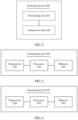
- FIG 1 is a schematic diagram of a communications system of a data transmission method according to this application.
- the communications system may be any one of the foregoing communications systems.
- the communications system 100 includes a network side device 102, and the network side device 102 may include a plurality of antenna groups.
- Each antenna group may include a plurality of antennas.
- one antenna group may include antennas 104 and 106, another antenna group may include antennas 108 and 110, and an additional group may include antennas 112 and 114.
- FIG 1 shows two antennas for each antenna group, but each group may include more or fewer antennas.
- the network side device 102 may additionally include a transmitter chain and a receiver chain.
- both the transmitter chain and the receiver chain may include a plurality of components (for example, a processor, a modulator, a multiplexer, a demodulator, a demultiplexer, or an antenna) related to signal sending and receiving.
- a processor for example, a processor, a modulator, a multiplexer, a demodulator, a demultiplexer, or an antenna
- the network side device 102 may communicate with a plurality of terminal devices (for example, a terminal device 116 and a terminal device 122). However, it may be understood that the network side device 102 may communicate with any quantity of terminal devices similar to the terminal device 116 or 122.
- the terminal devices 116 and 122 each may be, for example, a cellular phone, a smartphone, a portable computer, a handheld communications device, a handheld computing device, a satellite radio apparatus, a global positioning system, a PDA, and/or any other suitable device used for communication in the wireless communications system 100.
- the terminal device 116 communicates with the antennas 112 and 114.
- the antennas 112 and 114 send information to the terminal device 116 by using a forward link 118, and receive information from the terminal device 116 by using a reverse link 120.
- the terminal device 122 communicates with the antennas 104 and 106.
- the antennas 104 and 106 send information to the terminal device 122 by using a forward link 124, and receive information from the terminal device 122 by using a reverse link 126.
- the forward link 118 may use a band different from that used by the reverse link 120, and the forward link 124 may use a band different from that used by the reverse link 126.
- FDD Frequency Division Duplex
- the forward link 118 and the reverse link 120 may use a same band, and the forward link 124 and the reverse link 126 may use a same band.
- Each antenna group and/or region designed for communication is referred to as a sector of the network side device 102.
- an antenna group may be designed to communicate with a terminal device in a sector in a coverage area of the network side device 102.
- beamforming may be used in transmit antennas of the network side device 102, to increase signal to noise ratios of the forward links 118 and 124.
- a mobile device in a neighboring cell receives relatively low interference.
- the network side device 102, the terminal device 116, or the terminal device 122 may be a wireless communication sending apparatus and/or a wireless communication receiving apparatus.
- the wireless communications sending apparatus may encode the data for transmission.
- the wireless communications transmitting apparatus may obtain (for example, generate, receive from another communications apparatus, or store in a memory) a quantity of data bits that need to be transmitted to the wireless communications receiving apparatus by using a channel.
- the data bits may be included in a transport block (or a plurality of transport blocks) of data, and the transport block may be segmented to generate a plurality of code blocks.
- a transmit end (for example, a network device) of a signal obtains information about a channel between the transmit end and a receive end (for example, a terminal device), and may precode a transmit signal based on the obtained channel information.
- energy of the network device for transmitting a signal can be concentrated in a direction in which the terminal device is located, so that the terminal device can obtain a relatively high signal-to-noise ratio for signal receiving.
- the network device sends a plurality of layers of data streams to the terminal device, some or all interference between data streams may be eliminated in advance at the transmit end in this manner, thereby improving system performance.
- a matrix used by the transmit end for precoding is a precoding matrix.
- the embodiments of this application mainly relate to a solution about how the terminal device sends channel state information to the network device, so that the network device determines a precoding matrix based on the channel information.
- FIG 2 is a schematic flowchart of a channel state information transmission method according to an embodiment of this application.
- the method shown in FIG 2 may be applied to the foregoing system, for example, the method may be applied to a TDD system, an FDD system, or another system scenario. This is not limited in this embodiment of this application.
- the TDD system includes a terminal device and a network device, and the terminal device includes N antenna ports.
- a quantity of transmit channels of the terminal device is less than a quantity N of receive channels, and only n of the N antenna ports may be used to send uplink data and an uplink reference signal, and form a first antenna port set that may also be referred to as a transmit antenna port set St, where n ⁇ N, and the first antenna port set is a proper subset of the second antenna port set.
- the network device includes M antenna ports, and the M antenna ports may be used to receive the uplink data and the uplink reference signal, or send the downlink data and the downlink reference signal.
- a method 200 shown in FIG 2 includes the following steps.
- the terminal device sends a first reference signal through the first antenna port set.
- the first antenna port set includes n antenna ports, and n is a positive integer.
- the terminal device sends the first reference signal to the network device through the n antenna ports.
- the first reference signal may be, for example, a sounding reference signal (Sounding Reference Signal, SRS), and the first reference signal may be another type of reference signal.
- SRS Sounding Reference Signal
- the following uses an example in which the first reference signal is the SRS for description, but this is not limited in this embodiment of this application.
- the network device may obtain an uplink channel matrix H 1 T ⁇ C M ⁇ n from the n antenna ports to the M antenna ports of the network device through measurement of the SRS.
- the terminal device may send the first reference signal through the first antenna set once.
- the terminal device may send the first reference signal y times, and send the first reference signal through z antenna ports in the N antenna ports each time, and z antenna ports used to send the first reference signal this time are different from antenna ports used to previously send the first reference signal.
- the first antenna port set may include y antenna port subsets each including a same quantity of ports, each antenna port subset includes z antenna ports, and antenna ports in two antenna port subsets are different from each other.
- the terminal device sends the first reference signal to the network device through the y antenna port subsets y times, and sends the first reference signal through one antenna port subset each time.
- the terminal device may send the SRS a plurality of times, and sends the SRS for z antenna ports each time.
- the terminal device may send the SRS y times (y is a positive integer, for example, a value of y is 1, 2, 3, 4 ...), for example, first send the SRS through antenna ports 1 to z, ..., and send the SRS through the antenna ports (y-1)(z+1) to yz the y th time.
- the terminal device may send the first reference signal a plurality of times, and send the first reference signal through a different port each time.
- the network device may determine an uplink channel matrix by detecting the first reference signal for a plurality of times, and may further determine a corresponding downlink channel matrix according to reciprocity.
- the terminal device can determine, according to reciprocity, information about a downlink channel matrix corresponding to other z antenna ports. Therefore, the terminal device sends the first reference signal a plurality of times, so that information about a downlink channel matrix that is not learned of by the network device can be reduced. In this way, when the terminal device subsequently feeds back channel state information, the terminal device can feed back less channel state information, thereby reducing a data amount of channel state information, reducing resource overheads, and improving system performance.
- the SRS of z antenna ports separately sent at a plurality of sending moments introduce unsatisfactory factors, such as an additional delay and an insertion loss that is introduced when a transmit channel is switched between different ports, resulting in reduced accuracy of a downlink channel matrix obtained by the network device. Therefore, a quantity y of times for sending the SRS cannot be excessively large.
- y 1 or 2
- the network device sends the SRS through the n antenna ports once or twice, but this is not limited in this embodiment of this application.
- the network device sends a second reference signal.
- the network device may send the second reference signal to the terminal device through the M antenna ports.
- the terminal device may receive the second reference signal through the second antenna port set.
- the first antenna port set is a proper subset of the second antenna port set, in other words, the quantity of transmit antenna ports of the terminal device is less than the quantity of receive antenna ports, that is, the transmit antenna ports do not match the receive antenna ports (the quantities are not equal).
- the network device can only obtain a partial downlink channel matrix H 1 based on the uplink channel matrix. Therefore, in order to obtain a complete downlink channel matrix, the network device needs to send the second reference signal to the terminal device.
- the second reference signal may be, for example, a CSI-RS, and the second reference signal may be another type of reference signal.
- the following uses an example in which the second reference signal is a CSI-RS for description, but this is not limited in this embodiment of this application.
- the network device may send a non-beamformed (non-precoded/non-beamformed) CSI-RS for M antenna ports.
- the network device may send a beamformed (precoded/beamformed) CSI-RS.
- the non-beamformed CSI-RS means that the CSI-RS is not precoded by the network device, and the terminal device may measure a downlink channel matrix from the M antenna ports of the network device to the N antenna ports in the second antenna port set of the terminal device based on the non-beamformed CSI-RS.
- the beamformed CSI-RS means that the network device precodes a CSI-RS of each antenna port by using a precoding matrix, and the terminal device measures an equivalent downlink channel matrix from the M antenna ports of the network device to the N antenna ports in the second antenna port set of the terminal device based on the beamformed CSI-RS.
- the equivalent downlink channel matrix is a result of applying M precoding matrices on a downlink channel matrix from M 1 antennas or transmitting and receiving units (transmitting and receiving unit, TxRU) of the network device to the N antenna ports of the terminal device.
- the terminal device sends channel state information, where content of the channel state information is associated with a rank indicator RI, and the channel state information and the RI are determined based on the second reference signal.
- the terminal device may measure the CSI-RS, determine a value of the RI, and determine, based on the value of the RI, the content of the channel state information to be sent to the network device.
- the RI is used to indicate a quantity of data layers for downlink communication between the terminal device and the network device.
- the content of the channel state information may be flexibly determined based on the quantity of communication data layers.
- CSI includes different parameters in different CSI content.
- Different CSI content may also be referred to as different CSI types, and each CSI type corresponds to one parameter set.
- the CSI may include at least one of a CQI, the RI, and a PMI.
- the PMI may be a PMI indicating a channel eigenvector, a PMI indicating a channel vector, a PMI indicating a channel correlation matrix, an explicit feedback-based PMI, an implicit feedback-based PMI, and a codebook-based PMI that form a first set.
- the PMI indicating a channel eigenvector is used to indicate a channel eigenvector of the downlink channel matrix from the M antenna ports of the network device to the N antenna ports of the terminal device. Further, the PMI may have different feedback precision, and may further be classified into a high-precision PMI indicating a channel eigenvector and a low-precision PMI indicating a channel eigenvector. High precision indicates a more accurate channel eigenvector, but higher overheads are brought for feedback. Low accuracy indicates a less accurate channel eigenvector, but lower overheads are brought for feedback.
- the PMI indicating a channel vector is used to indicate one or more channel vectors, each channel vector is a downlink channel vector from the M antenna ports of the network device to one of the N antenna ports of the terminal device, and each channel vector has a length M.
- the PMI may have different feedback precision, and may further be classified into a high-precision PMI indicating a channel vector and a low-precision PMI indicating a channel vector.
- High precision indicates a more accurate channel vector, but higher overheads are brought for feedback.
- Low accuracy indicates a less accurate channel vector, but lower overheads are brought for feedback.
- the codebook-based PMI indicates that the PMI is selected from predefined codebooks, and the PMI may represent a channel eigenvector, a channel matrix, or a channel correlation matrix. Therefore, codebook-based PMIs are a type of PMIs. Specifically, the PMI is used to represent a channel eigenvector, a channel matrix, or a channel correlation matrix with high precision or low precision, and specific indicated content and/or indication precision may be configured by the network device by sending signaling or may be predefined.
- the explicit feedback-based PMI indicates that the PMI directly represents a channel eigenvector, a channel vector, or a channel correlation matrix without considering a receiver of the terminal device. Therefore, explicit feedback-based PMIs are a type of PMIs. Specifically, the PMI is used to represent a channel eigenvector, a channel matrix, or a channel correlation matrix with high precision or low precision, and specific indicated content and/or indication precision may be configured by the network device by sending signaling or may be predefined.
- the implicitly feedback-based PMI indicates that the PMI considers a receiver of the terminal device, is a PMI on which both the receiver of the terminal device and a channel eigenvector (or a channel vector or a channel correlation matrix) operate, and does not directly represent a channel eigenvector (or a channel vector or a channel correlation matrix). Therefore, explicit feedback-based PMIs are a type of PMIs. Specifically, the PMI is used to represent a channel eigenvector, a channel matrix, or a channel correlation matrix with high precision or low precision, and specific indicated content and/or indication precision may be configured by the network device by sending signaling or may be predefined.
- u 1 ,.., u x represent x eigenvectors of a matrix H s H H s on the sub-band, and x is a positive integer.
- the PMI indicating a channel eigenvector represents a PMI indicating the x eigenvectors, and a value of x may be recommended by the terminal device to the network device or configured by the network device.
- the PMI is a high-precision PMI
- the following form may be specifically used.
- the PMI includes a PMI 1 and a PMI 2.
- the PMI 1 indicates a group of base vectors ⁇ b 1, ..., b L ⁇ (when the network device uses a single-polarized antenna, b i ⁇ C M ⁇ 1 ; and when the network device uses a dual-polarized antenna, b i ⁇ C ( M /2) ⁇ 1 ), where L is a positive integer greater than 1.
- the PMI 2 includes x groups of linear combination coefficients, and each group of linear combination coefficients includes at least two non-zero coefficients.
- Each group of linear combination coefficients is used to perform linear combination on the group of base vectors indicated by the PMI 1, and a result of the linear combination is used to represent one eigenvector.
- the PMI 1 may indicate one group of base vectors for each polarization direction, and two groups of base vectors: ⁇ b 1 ,..., b L ⁇ and ⁇ b 1 ',..., b L ' ⁇ are different.
- More base vectors in the group of base vectors indicated by PMI 1, that is, a larger L, and more precise quantization of the x groups of linear combination coefficients included by the PMI 2 indicate that a result of the linear combination based on the PMI 1 and the PMI 2 of the PMI can represent an eigenvector more accurately.
- the PMI 1 is reported for the entire bandwidth, that is, broadband reporting; the PMI 2 is reported for each subband, that is, subband reporting.
- the PMI includes a PMI 2.
- the PMI 2 includes x groups of linear combination coefficients, and each group of linear combination coefficients includes at least two non-zero coefficients.
- Each group of linear combination coefficients represents one eigenvector of an equivalent downlink channel matrix from k antenna ports of the network device to the N antenna ports of the terminal device.
- the k antenna ports are in the M antenna ports and are selected by the terminal device based on measurement. Therefore, k is an integer less than or equal to M.
- the terminal device in addition to the PMI, the terminal device further needs to feed back third indication information, and the third indication information is used to indicate numbers of the k antenna ports.
- a larger quantity k of antenna ports selected by the terminal device and more precise quantification of the x groups of linear combination coefficients included in the PMI 2 indicate that a result obtained based on the PMI 2 can represent the eigenvector of the equivalent downlink channel more accurately.
- Selection of the k antenna ports is reported for the entire bandwidth, that is, broadband reporting; the PMI 2 is reported for each subband, that is, subband reporting.
- the high-precision PMI indicating a channel eigenvector also belongs to the explicit feedback-based PMI.
- the following form may be specifically used.
- the PMI includes a PMI 1 and a PMI 2.
- the PMI 1 indicates a group of base vectors ⁇ b 1 ,..., b L ⁇ .
- the PMI 2 is used to select a base vector from the group of base vectors when the network device uses a single-polarized antenna, and the PMI 2 is used to select a base vector from the group of base vectors and a phase difference between two polarization directions when the network device uses a dual-polarized antenna.
- x 2
- the PMI indicates eigenvectors u 1 and u 2
- e i is a vector with a length L, the i th element is 1, and other elements are 0.
- ⁇ is the phase difference between the two polarization directions, and may be selected from a predefined set. For example, the set may be 0 ⁇ 2 ⁇ 3 ⁇ 2 , or may include more values. This is not limited herein.
- the PMI 1 may also indicate two different groups of base vectors for antenna ports in the two polarization directions. This is similar to the above example, and details are not described again.
- the low-precision PMI indicating a channel eigenvector also belongs to the codebook-based PMI.
- the terminal device selects the PMI 1 and the PMI 2 from the codebooks, if the receiver of the terminal device is considered, the low-precision PMI indicating a channel eigenvector also belongs to the implicit feedback-based PMI.
- the PMI 1 is reported for the entire bandwidth, that is, broadband reporting; the PMI 2 is reported for each subband, that is, subband reporting.
- the PMI includes a PMI 2.
- e i is a vector with a length of M/2, the i th element is 1, other elements are 0, and e i is used to select the i th antenna port from M12 antenna ports.
- ⁇ is a phase difference between two polarization directions, and may be selected from a predefined set.
- the set may be 0 ⁇ 2 ⁇ 3 ⁇ 2 , or may include more values. This is not limited herein.
- W 2 approximately represents two eigenvectors of an equivalent downlink channel matrix. The PMI 2 is reported for each subband, that is, subband reporting.
- the low-precision PMI indicating a channel eigenvector may be the explicit feedback-based PMI, the implicit feedback-based PMI, or the codebook-based PMI.
- the network device can obtain an approximate representation of the eigenvector of the downlink channel matrix, to provide reference for determining a precoding matrix used for data.
- the PMI indicating a channel vector is a PMI used to indicate one or more row vectors of the channel matrix H s .
- h 1 ,..., h N represent N row vectors of H s , and a length of each vector is M.
- the PMI is used to represent y row vectors of H s , and y is a positive integer less than or equal to N.
- the PMI is a high-precision PMI
- the following form may be specifically used.
- the PMI includes a PMI 1 and a PMI 2.
- the PMI 1 indicates a group of base vectors ⁇ b 1, ..., b L ⁇ (when the network device uses a single-polarized antenna, b i ⁇ C M ⁇ 1 ; and when the network device uses a dual-polarized antenna, b i ⁇ C (M/2) ⁇ 1 ), where L is a positive integer greater than 1.
- the PMI 2 includes x groups of linear combination coefficients, and each group of linear combination coefficients includes at least two non-zero coefficients.
- Each group of linear combination coefficients is used to perform linear combination on the group of base vectors indicated by the PMI 1, and a result of the linear combination is used to represent one eigenvector.
- the PMI 1 may also indicate two different groups of base vectors for two polarization directions. This is similar to the above example, and details are not described again.
- the PMI 1 may also indicate two different groups of base vectors for antenna ports in the two polarization directions. This is similar to the above example, and details are not described again.
- the PMI 1 is reported for the entire bandwidth, that is, broadband reporting; the PMI 2 is reported for each subband, that is, subband reporting.
- the PMI includes a PMI 2.
- the PMI 2 includes y groups of linear combination coefficients, and each group of linear combination coefficients includes at least two non-zero coefficients.
- Each group of linear combination coefficients represents one channel vector of an equivalent downlink channel matrix from k antenna ports of the network device to the N antenna ports of the terminal device.
- the k antenna ports are in the M antenna ports and are selected by the terminal device based on measurement. Therefore, k is an integer less than or equal to M.
- the terminal device further needs to feed back third indication information, and the third indication information is used to indicate numbers of the k antenna ports.
- a larger quantity k of antenna ports selected by the terminal device and more precise quantification of the y groups of linear combination coefficients included in the PMI 2 indicate that a result obtained based on the PMI 2 can represent the eigenvector of the equivalent downlink channel more accurately.
- Selection of the k antenna ports is reported for the entire bandwidth, that is, broadband reporting; the PMI 2 is reported for each subband, that is, subband reporting.
- the high-precision PMI indicating a channel vector also belongs to the explicit feedback-based PMI.
- the following form may be specifically used.
- the PMI includes a PMI 1 and a PMI 2.
- the PMI 1 indicates a group of base vectors [ b 1 ,..., b L ⁇ .
- the PMI 2 is used to select a base vector from the group of base vectors when the network device uses a single-polarized antenna, and the PMI 2 is used to select a base vector from the group of base vectors and a phase difference between two polarization directions when the network device uses a dual-polarized antenna.
- y 2
- the PMI indicates eigenvectors h 1 and h 2
- e i is a vector with a length L, the i th element is 1, and other elements are 0.
- ⁇ is a phase difference between the two polarization directions, and may be selected from a predefined set. For example, the set may be 0 ⁇ 2 ⁇ 3 ⁇ 2 , or may include more values. This is not limited herein.
- the PMI 1 may also indicate two different groups of base vectors for antenna ports in the two polarization directions. This is similar to the above example, and details are not described again.
- the PMI 1 is reported for the entire bandwidth, that is, broadband reporting; the PMI 2 is reported for each subband, that is, subband reporting.
- the PMI includes a PMI 2.
- e i is a vector with a length of M12, the i th element is 1, other elements are 0, and e i is used to select the i th antenna port from M12 antenna ports.
- ⁇ is a phase difference between two polarization directions, and may be selected from a predefined set.
- the set may be 0 ⁇ 2 ⁇ 3 ⁇ 2 , or may include more values. This is not limited herein.
- the PMI 2 is reported for each subband, that is, subband reporting.
- Two row vectors of an equivalent downlink channel matrix are approximately represented by W 2 .
- the equivalent downlink channel matrix is H s [ w 1 ,..., w M ]
- row vectors are h 1 ,..., h N .
- Appropriate i, j, and ⁇ are selected, and the PMI 2 may approximately represent any two vectors in h 1 ,..., h N .
- the low-precision PMI indicating a channel vector also belongs to the codebook-based PMI.
- the terminal device selects the PMI from the codebooks, if the receiver of the terminal device is considered, the low-precision PMI indicating a channel vector also belongs to the implicit feedback-based PMI.
- the low-precision PMI indicating a channel vector may be the explicit feedback-based PMI, the implicit feedback-based PMI, or the codebook-based PMI.
- the network device can obtain an approximate representation of the downlink channel matrix, to provide reference for determining a precoding matrix used for data.
- the PMI indicating a channel correlation matrix is used to indicate a channel correlation matrix.
- a channel that the network device is interested in is a full channel matrix H s
- a channel correlation matrix is H s H H s .
- a channel that is corresponding to some of the N antenna ports of the terminal device and that the network device is interested in is represented as H s ' (which is a matrix formed by some rows in the full channel matrix H s ), and a channel correlation matrix is H s ' H H s '.
- the PMI may be used to indicate a plurality of eigenvectors of the channel correlation matrix (the terminal device needs to report a plurality of eigenvalues of a channel correlation matrix associated with a plurality of eigenvectors).
- a specific PMI form is similar to that described in the high-precision PMI indicating a channel eigenvector, and details are not described again.
- the PMI may be used to indicate a plurality of row vectors or column vectors of a channel correlation matrix.
- a specific PMI form is similar to that described in the PMI indicating a channel vector, and details are not described again.
- the PMI may be used to indicate a plurality of eigenvectors of the broadband channel correlation matrix.
- a specific PMI form is similar to that described in the PMI indicating a channel eigenvector, and details are not described again.
- the PMI may be used to indicate a plurality of row vectors or column vectors of the broadband channel correlation matrix.
- a specific PMI form is similar to that described in the PMI indicating a channel vector, and details are not described again.
- the first set includes the PMI indicating a channel eigenvector, the PMI indicating a channel vector, the PMI indicating a channel correlation matrix, the explicit feedback-based PMI, and the implicit feedback-based PMI.
- Precision of each type of PMI may be configured by using another method, for example, is configured by configuration information sent by the network device, or predefined, or recommended by the terminal device.
- the first set may further include another PMI type. This is not limited herein.
- elements of the first set may be obtained by further splitting the plurality of PMI types based on a feedback type.
- the first set includes the high-precision PMI indicating a channel eigenvector, the low-precision PMI indicating a channel eigenvector, the high-precision PMI indicating a channel vector, the low-precision PMI indicating a channel vector, the high-precision PMI indicating a channel correlation matrix, the low-precision PMI indicating a channel correlation matrix, the explicit feedback-based PMI, the implicit feedback-based PMI, and the codebook-based PMI.
- the first set may include the explicit feedback-based PMI and the codebook-based PMI.
- An indication precision of the explicit feedback-based PMI and whether the explicit feedback-based PMI specifically indicates a channel vector, a channel eigenvector, or a channel correlation matrix may be configured by using another method, for example, is configured by configuration information sent by the network device, or predefined, or recommended by the terminal device.
- a form of the first set may be modified in a manner similar to that described above, and is not limited to the form in the example.
- a first type of CSI content includes a CQI, an RI, and a first type of PMI (for example, the PMI indicating a channel eigenvector) in the PMIs
- a second type of CSI content includes a CQI, an RI
- a second type of PMI for example, the PMI indicating a channel correlation matrix
- a third type of CSI content includes a CQI and an RI
- a fourth type of CSI content includes only an RI.
- two pieces of CSI include same parameters, for example, both include a CQI/an RI, and a PMI, and the PMI is of a same type, the two pieces of CSI have same content. If two pieces of CSI include different parameters, or two pieces of CSI include different types of PMIs, the two pieces of CSI have different content.
- a PMI indicating a channel eigenvector and corresponding to the CQI/RI the first CSI content is the same as the second CSI content.
- the terminal device may determine CSI content based on a value of the RI, and a beneficial effect is that feedback overheads for the channel state information can compromise with feedback accuracy of the channel state information, and this is more flexible. Therefore, in this embodiment of this application, accuracy of the channel state information PMI can be improved while feedback overheads for the channel state information are reduced, thereby improving system performance.
- the following describes in detail the corresponding content of the channel state information determined by the terminal device based on the value of the RI.
- H 1 ⁇ C n ⁇ M is a downlink channel matrix from the M antenna ports of the network device to the n antenna ports in the first antenna port set of the terminal device, and may be obtained by the network device through measurement of an SRS.
- H 2 ⁇ C ( N - n ) ⁇ M is a downlink channel matrix from the M antenna ports of the network device to (N-n) antenna ports other than the first antenna port set in the second antenna port set of the terminal device, and is obtained by the terminal device through measurement of a CSI-RS.
- the content of the channel state information includes a channel quality indicator CQI and/or the RI, and the channel state information does not include a precoding matrix indicator PMI.
- the terminal device needs to calculate the CQI based on a PMI hypothesis. Because the PMI is not fed back, the network device knows only the partial channel matrix Hi, the terminal device needs to assume, based on the channel matrix Hi, a PMI used by the network device. The terminal device may assume, according to a predefined rule, a rule indicated by the network device, or a rule assumed by the terminal device based on measurement, the PMI used by the network device in this case.
- the terminal device first determines the RI through measurement of the CSI-RS, and assumes that with the RI, the network device uses RI primary eigenvectors of the matrix H 1 as a precoding matrix on a corresponding subband, and the terminal device may obtain a signal to interference plus noise ratio or another parameter of a received signal based on the PMI hypothesis, the RI, and a receiver (such as an MMSE receiver or an MMSE-IRC receiver) used by the terminal device, to obtain the CQI.
- a receiver such as an MMSE receiver or an MMSE-IRC receiver
- the terminal device may alternatively assume that the network device uses RI primary eigenvectors of a broadband channel correlation matrix (a specific definition is in the related content of the high-precision PMI indicating a channel correlation matrix) of the matrix H 1 as a precoding matrix on each subband, and the terminal device may obtain a signal to interference plus noise ratio or another parameter of a received signal based on the PMI hypothesis, the RI, and a receiver used by the terminal device, to obtain the CQI.
- the terminal device may also calculate the CQI by using another method. This is not limited herein.
- the content of the channel state information includes the CQI and/or the RI, and the channel state information further includes the PMI, where X1 is a positive integer less than or equal to N.
- the CQI is determined based on the RI and the PMI.
- the terminal device first determines the RI through measurement of the CSI-RS.
- the terminal device determines the PMI based on the RI and an estimation result of the downlink channel matrix H, and the terminal device may obtain a signal to interference plus noise ratio or another parameter of a received signal based on the PMI, the RI, and a receiver of the terminal device (such as an MMSE receiver or an MMSE-IRC receiver), to obtain the CQI.
- the CQI may also be calculated in another manner. This is not limited.
- the channel state information when RI ⁇ X1, the channel state information does not include the PMI, and when RI > X1, the channel state information includes the PMI.
- a value of X1 may be a system default value, a value determined by the terminal device, or a value indicated by the network device. This is not limited in this embodiment of this application.
- X1 may be 1 or 2, and is not limited in this embodiment of this application.
- RI 1
- the terminal device does not feed back an accurate PMI, so that the network device transmits data by using the PMI obtained based on the partial channel matrix H 1 .
- a caused performance loss is acceptable, and has little impact on overall network performance (in general, total network throughput is mainly determined by performance of a terminal device that simultaneously transmits a plurality of data streams in downlink communication, that is, RI > 1).
- a channel eigenvector obtained by the network device based on the partial channel matrix H 1 is slightly different from a channel eigenvector obtained by the network device based on the full channel matrix H.
- the eigenvector obtained based on the partial channel matrix is used to determine a precoding matrix used for data, a relatively small performance loss is caused, and relatively small multi-user interference is also caused to another terminal device. Therefore, the terminal device may not feed back the PMI, and this can greatly reduce the resource overheads for the channel state information and improve system performance.
- the channel state information fed back by the terminal device includes the PMI.
- the terminal device feeds back the PMI, so that the network device can obtain complete channel state information, and can further process data based on the accurate channel state information, thereby improving data transmission efficiency and the system performance.
- RI ⁇ X1 for example, RI ⁇ 2
- RI ⁇ 2 a value of the RI is relatively small, that is, there are a relatively small quantity of data layers between the network device and the terminal device. Therefore, the terminal device may not feed back the PMI obtained based on the full channel matrix H, and the network device may obtain a precoding matrix based on the obtained partial channel matrix H 1 . It may be considered that relatively small interference is caused between relatively small RI layers of data, and a downlink data transmission rate loss is relatively small. Therefore, the terminal device may not feed back the PMI when RI ⁇ X1, and this can greatly reduce the resource overheads for the channel state information and improve the system performance.
- the CSI content reported by the terminal device includes the PMI.
- the PMIs reported by these terminal devices based on the full channel matrix H match the matrix H more closely, interference between RI layers of data streams and interference between a plurality of terminal devices are greatly reduced, and this facilitates an increase in the system performance.
- time-frequency-code resources required to carry the content of the channel state information in the PUCCH is configured by the network device in advance by using signaling.
- the terminal device may first report the RI (for example, in a periodic CSI reporting mode, the terminal device reports the RI in a relatively long period, and subsequent reporting of the PMI and/or CQI is calculated based on a last reported RI), and the network device determines, based on a comparison between RI and X1, whether to allocate time-frequency-code resources for subsequently reporting the PMI.
- the network device does not allocate the time-frequency-code resources for reporting the PMI, reducing overheads used by the terminal device to report the CSI.
- the time-frequency-code resources can be allocated to other terminal devices, to implement PUCCH multiplexing of more terminal devices and improve utilization efficiency of system time-frequency-code resources.
- the network device allocates the time-frequency-code resources for reporting the PMI by using signaling (such as downlink control information (Downlink Control Information, DCI), a multiple access channel control element (multiple access channel Control Element, MAC CE), or radio resource control (Radio Resource Control, RRC) signaling).
- DCI Downlink Control Information
- MAC CE multiple access channel Control Element
- RRC Radio Resource Control
- the time-frequency-code resources are no longer allocated to other terminal devices, avoiding collisions of time-frequency-code resources of PUCCHs of a plurality of terminal devices.
- the content of the channel state information reported by the terminal device is carried in an uplink shared channel (Physical Uplink Shared Channel, PUSCH)
- time-frequency-code resources required to carry the content of the channel state information in the PUSCH is configured by the network device in advance by using signaling.
- the terminal device may first report the RI, and the network device determines, based on a comparison between RI and X1, whether to allocate time-frequency-code resources for subsequently reporting the PMI.
- the network device does not allocate the time-frequency-code resources for reporting the PMI, reducing overheads used by the terminal device to report the CSI. In this case, the time-frequency-code resources can be allocated for uplink data transmission, improving utilization efficiency of system time-frequency-code resources. If RI > X1, the network device allocates, by using signaling (such as downlink control information DCI), the time-frequency-code resources for reporting the PMI. The network device flexibly determines whether to allocate the resources for reporting the PMI, and improvement of the utilization efficiency of the time-frequency-code resources can compromise with improvement of PMI feedback accuracy.
- signaling such as downlink control information DCI
- the PMI in the channel state information may be any type of PMI in the first set. This is not limited in this embodiment of this application.
- the content of the channel state information may include the PMI.
- the content of the channel state information may be flexibly selected. This is not limited in this embodiment of this application.
- the first PMI and the second PMI are different elements in the first set, and each element in the first set represents a different PMI type.
- the first set includes at least two PMI types in the PMI indicating a channel eigenvector, the PMI indicating a channel vector, the PMI indicating a channel correlation matrix, the explicit feedback-based PMI, the implicit feedback-based PMI, and the codebook-based PMI, and X2 is a positive integer less than or equal to N.
- the first PMI and the second PMI are of different types.
- the first PMI is the codebook-based PMI
- the second PMI is the PMI indicating a channel eigenvector
- the first PMI is the implicit feedback-based PMI
- the second PMI is the explicit feedback-based PMI (for example, the PMI indicating a channel matrix, an eigenvector, or a correlation matrix)
- the first PMI is the high-precision PMI indicating an eigenvector
- the second PMI is the high-precision PMI indicating a channel correlation matrix.
- a type of the PMI in the channel state information may be flexibly determined based on a value relationship between a value of the RI and X2, to flexibly compromise between reducing feedback overheads for the channel state information and improving system performance.
- the first PMI is a low-precision PMI (such as the low-precision PMI indicating a channel eigenvector)
- the second PMI is a high-precision PMI (such as the high-precision PMI indicating a channel eigenvector).
- RI is less than X2
- the first PMI is fed back, to reduce the feedback overheads for the channel state information.
- RI is greater than X2, the first PMI is fed back, to improve the system performance.
- the first PMI may be a low-precision PMI indicating a channel eigenvector, for example, the first PMI is used to indicate RI eigenvectors of a downlink channel matrix from the k antenna ports to N or (n + X2) antenna ports.
- the second PMI may be a high-precision PMI indicating a downlink channel vector, for example, the PMI is used to indicate X2 downlink channel vectors, and each of the X2 downlink channel vectors is a downlink channel vector from the k antenna ports to one of X2 antenna ports in the second antenna port set.
- the k antenna ports are selected by the terminal device from the M antenna ports through which the network device sends the second reference signal.
- a value of X2, and/or the X2 antenna ports may be notified by the network device to the terminal device by sending signaling, for example, the X2 antenna ports may be in (N - n) antenna ports other than the first antenna port set in the second antenna port set, that is, X2 is a positive integer less than or equal to (N - n).
- the X2 antenna ports may also include ports in the first antenna port set.
- the terminal device reports the first PMI
- the reported CQI is determined based on the RI and the first PMI.
- the terminal device first determines the RI through measurement of the CSI-RS.
- the terminal device determines the first PMI based on the RI and an estimation result of the downlink channel matrix H, and the terminal device may obtain a signal to interference plus noise ratio or another parameter of a received signal based on the first PMI, the RI, and a receiver of the terminal device (such as an MMSE receiver or an MMSE-IRC receiver), to obtain the CQI.
- the CQI may also be calculated in another manner. This is not limited.
- the terminal device first determines the RI through measurement of the CSI-RS. The terminal determines the second PMI based on the RI and the estimation result of the downlink channel matrix H.
- the terminal Based on a channel matrix represented by the second PMI, the channel matrix that is between the k antenna ports and the n antenna ports and that is obtained by the network device through measurement of the SRS (which may also be measured by the terminal), and a predefined rule or a rule notified by the network device, the terminal assumes a precoding matrix used by the network device.
- the terminal device may obtain a signal to interference plus noise ratio or another parameter of a received signal based on the RI, the precoding matrix, and a receiver of the terminal device (such as an MMSE receiver or an MMSE-IRC receiver), to obtain the CQI. Due to high precision, a relatively large quantity of time-frequency resources are occupied to report the PMI, but the system performance can be effectively improved.
- the method in this embodiment of this application may further include:
- the terminal device sends second indication information, to indicate a type of the first PMI or the second PMI.
- the network device may determine the reported PMI type based on the second indication information, to determine a downlink precoding matrix. For example, if the first PMI indicates RI eigenvectors of a downlink channel matrix from the M antenna ports of the network device to the N or (n + X2) antenna ports, the network device learns of, based on the PMI, an eigenvector of a downlink channel matrix from the network device to the terminal device. In a single-user transmission mode, the RI eigenvectors may be used as the precoding matrix for data.
- the network device may determine, based on information such as the RI eigenvectors and PMIs reported by other terminal devices, the precoding matrix used for data. If the first PMI indicates a channel vector of a downlink channel matrix from the M antenna ports of the network device to (N-n) non-transmit antenna ports of the terminal, the network device may obtain information about a full channel matrix based on the PMI and the channel vector that is between the M antenna ports and the n transmit antenna ports and that is measured by the network device based on the SRS. In the single-user transmission mode, RI eigenvectors of the full channel matrix may be used as the precoding matrix for data. During multi-user transmission, the network device may determine, based on information such as the full channel matrix and PMIs reported by other terminal devices, the precoding matrix used for data.
- the terminal device sends the second indication information, and the second indication information indicates a value of N.
- the network device may determine a value relationship between RI and (N-n) based on the value of N and the RI that is reported by the terminal device, so that the network device determines whether the type of PMI reported by the terminal device is the first PMI or the second PMI, to determine the downlink precoding matrix. A specific determining manner is described above, and details are not described again.
- the terminal device can flexibly determine the content of the channel state information based on different values of the RI, the terminal device can send the second indication information to indicate a specific type of the PMI in the fed back channel state information, so that the network device determines the type of the PMI based on the second indication information, to determine the precoding matrix.
- time-frequency-code resources required to carry the content of the channel state information in the PUCCH is configured by the network device in advance by using signaling.
- the terminal device may first report the RI (for example, in a periodic CSI reporting mode, the terminal device reports the RI in a relatively long period, and subsequent reporting of the PMI and/or CQI is calculated based on a last reported RI), and the network device determines, based on a comparison between RI and X2, whether to allocate time-frequency-code resources for subsequently reporting the PMI.
- the network device allocates, through signaling (such as DCI, a MAC CE, or RRC), time-frequency-code resources for reporting the first PMI. If RI > X2, the network device allocates, through signaling (such as DCI, a multiple access channel control element MAC CE, or radio resource control RRC signaling), time-frequency-code resources for reporting the second PMI. If the content of the channel state information reported by the terminal device is carried in an uplink shared channel (PUSCH), time-frequency-code resources required to carry the content of the channel state information in the PUSCH is configured by the network device in advance by using signaling.
- signaling such as DCI, a MAC CE, or RRC
- the terminal device may first report the RI, and the network device determines, based on a comparison between RI and X1, whether to allocate time-frequency-code resources for subsequently reporting the PMI. If RI ⁇ X1, the network device does not allocate time-frequency-code resources for reporting the first PMI. If RI > X1, the network device allocates, by using signaling (such as downlink control information DCI), the time-frequency-code resources for reporting the second PMI. When the first PMI and the second PMI are reported by using different overheads, the network device can flexibly allocate, by comparing RI and X2, the time-frequency-code resources required to report the PMI, thereby improving utilization efficiency of system time-frequency-code resources.
- DCI downlink control information
- the terminal device and the network device when the terminal device and the network device determine the content of the channel state information based on the value relationship between the value of the RI and the preset X2, because both the network device and the terminal device know the value of X2, when the content of the channel state information includes the RI, the terminal device may not send the second indication information to the network device, and the network device may determine the type of the PMI based on the relationship between RI and X2.
- the value of X2 may be a system default value, a value determined by the terminal device, or a value indicated by the network device. This is not limited in this embodiment of this application.
- X2 may be equal to P
- P is a quantity of antenna ports included in a third antenna port set
- the third antenna port set is a proper subset of the second antenna port set
- the third antenna port set is different from the first antenna port set, 1 ⁇ P ⁇ N - n
- P is an integer.
- the second antenna port set is a universal set
- the third antenna port set is a complementary set of the first port set.
- the P antenna ports in the third port set are all or some of the (N - n) antenna ports other than the n antenna ports in the N antenna ports.
- the method may further include: sending, by the network device, a first indication message, where the first indication message is used to indicate the third antenna port set.
- the first indication information indicates P specific antenna ports in the third antenna port set that are in the (N - n) antenna ports other than the n antenna ports in the N antenna ports.
- the content of the channel state information includes the first PMI, where the first PMI is used to indicate RI eigenvectors of a downlink channel matrix from the k antenna ports to the N antenna ports or (n + P) antenna ports, the k antenna ports are antenna ports through which the second reference signal is sent, and k is a positive integer.
- the k antenna ports may be the M antenna ports of the network device or k antenna ports selected by the terminal device from the M antenna ports, for example, selected based on receive power or receive quality of a CSI-RS of each antenna port.
- P may be an integer less than (N - n).
- N antenna ports of the terminal device are sheltered/blocked due to holding the terminal device by a hand or other factors, the RI eigenvectors of a downlink channel from the k antenna ports to all the N antenna ports of the terminal is fed back, and this may cause performance degradation. This is because receive power of a received signal of blocked antenna ports is very low, channel estimation results corresponding to the blocked antenna ports are very inaccurate, and the RI eigenvectors are also inaccurate in this case.
- the terminal device may have a plurality of antenna port groups (for example, each antenna port group includes a plurality of antenna ports on one antenna panel) and send the SRS through only n antenna ports in one antenna port group. In this case, the network device further expects to know channel state information corresponding to P antenna ports in another antenna port group.
- the terminal device only needs to feed back eigenvectors of channels corresponding to (n + P) antenna ports, and does not need to feed back eigenvectors of channels corresponding to all receiving antenna ports.
- P may be equal to (N - n).
- the terminal device feeds back the RI eigenvectors that are of the downlink channel matrix from the k antenna ports to the N antenna ports and that are indicated by the first PMI.
- the second indication information sent by the terminal device may be used to indicate the value of N.
- the network device may determine a value relationship between RI and (N-n) based on the value of N and the RI that is reported by the terminal device, so that the network device determines whether the type of PMI reported by the terminal device is the first PMI or the second PMI, to determine the downlink precoding matrix. A specific determining manner is described above, and details are not described again.
- the network device may obtain the full channel matrix H or an eigenvector of a partial matrix that is in the matrix H and that the network device is interested in, to determine the precoding matrix used for data.
- the content of the channel state information includes the second PMI, and the second PMI is used to indicate a correlation matrix of the downlink channel matrix from the k antenna ports to the P antenna ports.
- a specific manner of feeding back a correlation matrix may be to feed back P eigenvectors of the matrix.
- the terminal device further needs to report related information of P non-zero eigenvalues, and the P non-zero eigenvalues are associated with the P reported eigenvectors.
- the P eigenvalues may be directly quantized and reported as the related information of the eigenvalues.
- the eigenvalues may first be divided by a numeric Y, to obtain the related information of the eigenvalues.
- the numeric Y is selected properly, and a benefit of dividing by the numeric Y is to reduce a quantized interval and a quantity of bits required for quantization.
- the numeric Y may be predefined or notified by the network device.
- the numeric Y may be a maximum non-zero eigenvalue of a correlation matrix of the partial channel matrix H 1 . Because the network device already obtains the maximum non-zero eigenvalue of H 1 through measurement of the SRS, the network device can recover the eigenvalue based on the related information of the eigenvalue reported by the terminal device.
- the network device can recover the correlation matrix of the downlink channel matrix from the k antenna ports to the P antenna ports based on the P eigenvectors and the P eigenvalues.
- the network device already obtains the correlation matrix of the partial channel matrix H 1 through measurement of the SRS. Therefore, the network device can obtain the correlation matrix of the full channel matrix H, to further determine the precoding matrix used for data.
- the second PMI may be of another type.
- the content of the channel state information includes the second PMI, and the second PMI is used to indicate P channel vectors of the downlink channel matrix from the k antenna ports to the P antenna ports.
- Each channel vector is a channel vector between the first of the P antenna ports and the k antenna ports, and is a vector with a length k.
- the advantage of determining, by comparing the value relationship between RI and P, whether to report the first PMI or the second PMI is that the network device can obtain the information about the full channel matrix H with lowest feedback overheads. It is assumed that the terminal device feeds back, with same precision, the eigenvectors indicated by the first PMI and the eigenvectors of the correlation matrix that are indicated by the second PMI. For example, two types of PMIs are fed back by using the previously PMI1 + PMI2 method, the PMI 1 is broadband feedback, and the PMI 2 is sub-band feedback.
- a PMI 1 indicates a group of base vectors ⁇ b 1 ,..., b L ⁇ , and L is the same in feedback of the two PMI types.
- a PMI 2 includes a plurality of groups of linear combination coefficients, each group of linear combination coefficients includes L non-zero coefficients, and a quantity of quantized bits of each coefficient is the same in feedback of the two PMI types.
- the PMI 1 brings same feedback overheads regardless of whether the first PMI or the second PMI is fed back.
- the PMI 2 includes RI groups of linear combination coefficients
- the PMI 2 includes P groups of linear combination coefficients.
- the advantage of determining, by comparing the value relationship between RI and P, whether to report the first PMI or the second PMI is that the network device can obtain the information about the full channel matrix H with lowest feedback overheads.
- the terminal device feeds back, with the same precision, the eigenvectors indicated by the first PMI and the correlation matrix indicated by the second PMI.
- the correlation matrix may be reported by reporting a non-zero eigenvalue of the correlation matrix and an eigenvector corresponding to the non-zero eigenvalue. Because a correlation matrix of the downlink channel matrix from the k antenna ports to the P antenna ports has a maximum of P non-zero eigenvalues, the second PMI needs to indicate a maximum of P eigenvectors. Therefore, when 1 ⁇ RI ⁇ P, PMI 2 reporting overheads caused by reporting the first PMI is less than PMI 2 reporting overheads caused by reporting the second PMI; and when RI > P, the PMI 2 reporting overheads caused by reporting the second PMI is less than the PMI 2 reporting overheads caused by reporting the first PMI.
- the terminal device determines the content of the fed back channel state channel based on the value relationship between RI and P, and can determine whether the PMI in the fed back channel state information is an eigenvector or a channel correlation matrix. Therefore, the channel state information may be reported by using lowest overheads, so that the network device obtains complete CSI, and system performance can be improved.
- time-frequency-code resources required to carry the content of the channel state information in the PUCCH is configured by the network device in advance by using signaling.
- the terminal device may first report the RI (for example, in a periodic CSI reporting mode, the terminal device reports the RI in a relatively long period, and subsequent reporting of the PMI and/or CQI is calculated based on a last reported RI), and the network device determines, based on a comparison between RI and P, whether to allocate time-frequency-code resources for subsequently reporting the PMI.
- the network device allocates, through signaling (such as DCI, a MAC CE, or RRC), time-frequency-code resources for reporting the first PMI. If RI > P, the network device allocates, through signaling (such as DCI, a multiple access channel control element MAC CE, or radio resource control RRC signaling), time-frequency-code resources for reporting the second PMI. If the content of the channel state information reported by the terminal device is carried in an uplink shared channel (PUSCH), time-frequency-code resources required to carry the content of the channel state information in the PUSCH is configured by the network device in advance by using signaling.
- signaling such as DCI, a MAC CE, or RRC
- the terminal device may first report the RI, and the network device determines, based on a comparison between RI and X1, whether to allocate time-frequency-code resources for subsequently reporting the PMI. If 1 ⁇ RI ⁇ P, the network device does not allocate time-frequency-code resources for reporting the first PMI. If RI > P, the network device allocates, by using signaling (such as downlink control information DCI), time-frequency-code resources for reporting the second PMI. By comparing RI with P, the network device can allocate a relatively small quantity of time-frequency-code resources to the terminal device to report the PMIs, to minimize reporting overheads, and can also obtain the complete CSI, to improve system performance.
- DCI downlink control information
- the content of the channel state information is associated with the RI and the quantity P of antenna ports in the third antenna port set.
- the specific content of the channel state information is respectively described when 1 ⁇ RI ⁇ P and when RI > P.
- the channel state information fed back by the terminal device may include only the CQI and/or RI, but not include the PMI.
- the channel state information fed back by the terminal device may further include the PMI, for example, the PMI is the first PMI or the second PMI. This is not limited in this embodiment of this application.
- the content of the channel state information may not include the first PMI, but include the second PMI.
- the content of the channel state information may be flexibly selected. This is not limited in this embodiment of this application.
- P may indicate P specific antenna ports in the (N - n) antenna ports other than the n antenna ports in the N antenna ports.
- P may be equal to (N - n), or may be less than (N - n). This is not limited in this embodiment of this application.
- the terminal device sends a non-beamformed (non-precoded) SRS of the n antenna ports in an uplink channel.
- the network device obtains an uplink channel H 1 T ⁇ C n ⁇ M from the n transmit ports to the network device through measurement of the SRS.
- the network device sends a non-beamformed (non-precoded/non-beamformed) CSI-RS through the M antenna ports.
- H 2 ⁇ C P ⁇ k represents a downlink channel matrix from the network device to other P non-transmit ports of the terminal.
- the terminal device feeds back the CSI based on a measurement result, where the CSI includes the CQI and/or the RI.
- the CSI further includes the first PMI.
- the first PMI includes base vector indication information (denoted by a PMI 11 herein) and RI groups of linear combination coefficients (denoted by a PMI 12 herein).
- the PMI 11 is used to indicate a group of base vectors ⁇ b 1 ,..., b L ⁇ (that is, the PMI 1 described above; when the network device uses a single-polarized antenna, b i ⁇ C M ⁇ 1 , and when the network device uses dual polarization directions, b i ⁇ C M 2 ⁇ 1 ).
- the PMI 12 is used to perform linear combination on the group of base vectors indicated by the PMI 1, to obtain RI eigenvectors (the PMI12 is the PMI 2 described above).
- One group of linear combination coefficients is used to perform linear combination on the group of base vectors, to represent one eigenvector.
- the RI eigenvectors are used to represent eigenvectors v 1 ..., v RI of a downlink channel matrix H H H .
- the CSI further includes the second PMI.
- the second PMI includes base vector indication information (denoted by a PMI 21 herein) and P groups of linear combination coefficients (denoted by a PMI 22 herein).
- the PMI 21 is used to indicate a group of base vectors (that is, the PMI 1 described above) (when the network device uses a single-polarized antenna, b i ⁇ C M ⁇ 1 , and when the network device uses dual polarization directions, b i ⁇ C M 2 ⁇ 1 ).
- the PMI 22 is used to perform linear combination on the group of base vectors indicated by the PMI 1 (the PMI 22 is the PMI2 described above), to obtain P eigenvectors of the correlation matrix of the downlink channel matrix from the k antenna ports to the P antenna ports.
- the terminal device further reports related information of P non-zero eigenvalues of the correlation matrix of the downlink channel matrix from the k antenna ports to the P antenna ports.
- the CSI further includes the second PMI.
- the second PMI includes base vector indication information (denoted by a PMI 31 herein) and P groups of linear combination coefficients (denoted by a PMI 32 herein).
- the PMI 31 is used to indicate a group of base vectors ⁇ b 1 , ...,b L ⁇ (that is, the PMI 1 described above) (when the network device uses a single-polarized antenna, b i ⁇ C M ⁇ 1 , and when the network device uses dual polarization directions, b i ⁇ C M 2 ⁇ 1 ).
- k may be M, or may be a numeric less than M. This is not limited in this embodiment of this application.
- k may represent the quantity of ports through which the second reference signal is sent. For example, if the network device sends the precoded second reference signal (CSI-RS) through the M antenna ports, and the terminal device learns, by measuring the CSI-RS, that channel states corresponding to some of the M antenna ports are relatively poor, channel state information corresponding to the antenna ports with relatively poor channel states may not be reported, and the terminal selects to report downlink channel state information from only the k antenna ports in the M antenna ports to the terminal device.
- CSI-RS precoded second reference signal
- the method 200 in this embodiment of this application may further include: sending, by the terminal device, third indication information, to indicate the k antenna ports.
- the third indication information indicates numbers or identifiers of the k antenna ports, or the third indication information indicates k specific antenna ports that are in the M antenna ports and that are corresponding to the state information reported by the terminal device.
- the first PMI indicates RI groups of linear combination coefficients, and each group of linear combination coefficients is used to represent one eigenvector.
- the second PMI indicates P groups of coefficients, and each group of coefficients is used to represent one of the P eigenvectors of the correlation matrix of the downlink channel matrix from the k antenna ports to the P antenna ports.
- P indicates P specific antenna ports in the (N - n) antenna ports other than the n antenna ports in the N antenna ports.
- P may be equal to (N - n), or may be less than (N - n). This is not limited in this embodiment of this application.
- the terminal device sends a non-beamformed (non-precoded) SRS of the n antenna ports in the uplink channel.
- the network device obtains an uplink channel H 1 T ⁇ C n ⁇ M from n transmit ports to the network device through measurement of the SRS,
- a T represents a transpose of a matrix A, and n is a positive integer.
- the network device sends the beamformed (precoded/beamformed) CSI-RS through the M antenna ports in the downlink channel.
- Each antenna port corresponds to one precoding matrix, and a CIS-RS sent through the port is precoded by using a corresponding precoding matrix.
- the precoding matrix W is determined by the network device, and is not known by the terminal device.
- H 2 ⁇ C (P) ⁇ M represents the downlink channel matrix from the network device to the P antenna ports of the terminal.
- the terminal device feeds back port selection information and/or the CSI based on a measurement result of the equivalent channel.
- the port selection information is used to instruct the network device to select the k antenna ports from the M antenna ports, and k is a positive integer less than or equal to M.
- the CSI includes the CQI and/or the RI.
- the CSI further includes the first PMI.
- the first PMI indicates RI groups of linear combination coefficients, and each group of linear combination coefficients includes k coefficients. Each group of linear combination coefficients is used to represent one eigenvector.
- the RI groups of coefficients respectively represent eigenvector v 1 ,..., v RI of an equivalent channel matrix H k H H k corresponding to the selected k antenna ports, and H k ⁇ C ( n + P ) ⁇ k represents a matrix including k column vectors of H corresponding to the k antenna ports selected by the terminal device.
- the first PMI may be used to instruct the network device to perform linear combination on precoding matrices corresponding to the selected k antenna ports, to obtain the precoding matrix used for data transmission.
- the CSI further includes the second PMI
- the second PMI indicates P groups of coefficients
- each group of coefficients includes k coefficients.
- the CSI further includes related information of the P non-zero eigenvalues of the correlation matrix.
- the CSI further includes the second PMI
- the second PMI indicates P groups of coefficients, and each group of coefficients includes k coefficients.
- the method 200 in this embodiment of this application may further include: sending, by the terminal device, third indication information, to indicate the k antenna ports.
- the third indication information indicates numbers or identifiers of the k antenna ports, or the third indication information indicates k specific antenna ports that are in the m antenna ports and that are corresponding to the state information reported by the terminal device.
- the following describes a terminal device in embodiments of this application with reference to FIG 3 and FIG 5 , and describes a network device in embodiments of this application with reference to FIG 4 and FIG. 6 .
- FIG 3 shows a schematic block diagram of a terminal device 300 according to an embodiment of this application.
- the terminal device 300 includes a processing unit 310 and a transceiver unit 320.
- the processing unit 310 controls the transceiver unit 320 to send a first reference signal through a first antenna port set, where the first antenna port set includes n antenna ports, and n is a positive integer;
- the terminal device may determine the CSI content based on a value of the RI, and feedback overheads for the channel state information can compromise with feedback precision of the channel state information, to more flexibly determine the content of the channel state channel. Therefore, in this embodiment of this application, accuracy of the channel state information can be improved while the feedback overheads for the channel state information are reduced, thereby improving system performance.
- X1 1.
- the content of the channel state information includes a CQI and/or the RI, and the channel state information further includes a first PMI; and when RI > X2, the content of the channel state information includes a CQI and/or the RI, and the channel state information further includes a second PMI.
- the first PMI and the second PMI are different elements in a first set, each element in the first set represents a different PMI type, the first set includes at least two PMI types in a PMI indicating a channel eigenvector, a PMI indicating a channel vector, a PMI indicating a channel correlation matrix, a codebook-based PMI, an explicit feedback-based PMI, and an implicit feedback-based PMI, and X2 is a positive integer less than or equal to N.
- X2 is equal to P
- P is a quantity of antenna ports included in a third antenna port set
- the third antenna port set is a proper subset of the second antenna port set
- the third antenna port set is different from the first antenna port set, 1 ⁇ P ⁇ N - n
- P is an integer
- X2 is equal to P
- P is a quantity of antenna ports included in a third antenna port set
- the third antenna port set is a proper subset of the second antenna port set
- the third antenna port set is different from the first antenna port set, 1 ⁇ P ⁇ N - n
- P is an integer
- the channel state information includes the second PMI
- the second PMI is used to indicate a channel correlation matrix of a downlink channel matrix from k antenna ports to the P antenna ports
- the k antenna ports are antenna ports through which the network device sends the second reference signal.
- the CQI is determined based on the RI, the second PMI, a channel matrix between the k antenna ports and the n antenna ports, and the k antenna ports are antenna ports through which the second reference signal is sent; or when RI > P, the channel state information includes the second PMI, the second PMI is used to indicate P channel vectors, each of the P vectors is a downlink channel vector from k antenna ports to one of the P antenna ports, and the k antenna ports are antenna ports through which the second reference signal is sent.
- the first PMI includes base vector indication information and RI groups of linear combination coefficients, where the base vector indication information is used to indicate a group of base vectors, the group of base vectors includes at least two base vectors, and each group of linear combination coefficients is used to perform linear combination on the group of base vectors to represent one eigenvector.
- the second PMI includes base vector indication information and P groups of linear combination coefficients, where the base vector indication information is used to indicate a group of base vectors, the group of base vectors includes at least two base vectors, and each group of linear combination coefficients is used to perform linear combination on the group of base vectors to represent one eigenvector of the channel correlation matrix; or the second PMI includes base vector indication information and P groups of linear combination coefficients, where the base vector indication information is used to indicate a group of base vectors, the group of base vectors includes at least two base vectors, and each group of linear combination coefficients is used to perform linear combination on the group of base vectors to represent one channel vector.
- the transceiver unit is further configured to send fourth indication information, where the fourth indication information is used to indicate related information of P eigenvalues of the channel correlation matrix, and the P eigenvalues are associated with P eigenvectors of the channel correlation matrix.
- the first PMI indicates RI groups of linear combination coefficients, and each group of linear combination coefficients is used to represent one eigenvector.
- the second PMI indicates P groups of channel coefficients, and each group of channel coefficients is used to represent one eigenvector of the channel correlation matrix; or the second PMI indicates P groups of channel coefficients, and each group of channel coefficients is used to represent one channel vector.
- the transceiver unit is further configured to receive a first indication message, where the first indication message is used to indicate the third antenna port set.
- the third antenna port set is a complement set of the first port set, and a union of the third antenna port set and the first port set is the second port set.
- the transceiver unit is further configured to send second indication information, where the second indication information is used to indicate a PMI type of the first PMI or the second PMI; or the second indication information is used to indicate a value of N.
- the transceiver unit is further configured to send third indication information, where the third indication information is used to indicate the k antenna ports.
- the first reference signal is a sounding reference signal SRS.
- the second reference signal is a channel state information-reference signal CSI-RS.
- the terminal device may determine the CSI content based on the value of the RI, and the feedback overheads for the channel state information can compromise with the feedback precision of the channel state information, to more flexibly determine the content of the channel state channel. Therefore, in this embodiment of this application, the accuracy of the channel state information can be improved while the feedback overheads for the channel state information are reduced, thereby improving the system performance.
- the terminal device 300 shown in FIG 3 can implement processes related to the terminal device in the method embodiment in FIG 2 . Operations and/or functions of modules in the terminal device 300 are respectively used to implement corresponding procedures in the method embodiment in FIG 2 . For details, refer to the descriptions in the method embodiment. To avoid repetition, detailed descriptions are appropriately omitted herein.
- FIG 4 shows a schematic block diagram of a network device 400.
- the network device 400 includes a processing unit 410 and a transceiver unit 420.
- the processing unit 410 controls the transceiver unit 420 to receive a first reference signal, where the first reference signal is sent by a terminal device through a first antenna port set, the first antenna port set includes n antenna ports, and n is a positive integer;
- the content of the channel state information received by the network device is associated with the rank indicator RI.
- the channel state information may be flexibly determined by the terminal device based on a value of the RI when a data amount of the channel state information compromises with feedback precision of the channel state information. Therefore, in this embodiment of this application, accuracy of the channel state information can be improved while feedback overheads for the channel state information are reduced, so that the network device can perform precoding based on the channel state information, thereby improving system performance.
- X1 1.
- the content of the channel state information includes a CQI and/or the RI, and the channel state information further includes a first PMI; and when RI > X2, the content of the channel state information includes a CQI and/or the RI, and the channel state information further includes a second PMI.
- the first PMI and the second PMI are different elements in a first set, each element in the first set represents a different PMI type, and the first set includes at least two PMI types in a PMI indicating a channel eigenvector, a PMI indicating a channel vector, a PMI indicating a channel correlation matrix, a codebook-based PMI, an explicit feedback-based PMI, and an implicit feedback-based PMI; and X2 is a positive integer less than or equal to N, N represents a quantity of antenna ports in the second antenna port set through which the terminal device receives the second reference signal, N is a positive integer, n ⁇ N, and the first antenna port set is a proper subset of the second antenna port set.
- X2 is equal to P
- P is a quantity of antenna ports included in a third antenna port set
- the third antenna port set is a proper subset of the second antenna port set
- the third antenna port set is different from the first antenna port set, 1 ⁇ P ⁇ N - n
- P is an integer
- the channel state information includes the first PMI, where the first PMI is used to indicate RI eigenvectors of a downlink channel matrix from the k antenna ports to the N antenna ports or (n + P) antenna ports.
- the CQI is determined based on the RI and the first PMI.
- X2 is equal to P
- P is a quantity of antenna ports included in a third antenna port set
- the third antenna port set is a proper subset of the second antenna port set
- the third antenna port set is different from the first antenna port set, 1 ⁇ P ⁇ N - n
- P is an integer
- the CQI is determined based on the RI, the second PMI, and a channel matrix between the k antenna ports and the n antenna ports.
- the first PMI includes base vector indication information and RI groups of linear combination coefficients, where the base vector indication information is used to indicate a group of base vectors, the group of base vectors includes at least two base vectors, and each group of linear combination coefficients is used to perform linear combination on the group of base vectors to represent one eigenvector.
- the second PMI includes base vector indication information and P groups of linear combination coefficients, where the base vector indication information is used to indicate a group of base vectors, the group of base vectors includes at least two base vectors, and each group of linear combination coefficients is used to perform linear combination on the group of base vectors to represent one eigenvector of the channel correlation matrix; or the second PMI includes base vector indication information and P groups of linear combination coefficients, where the base vector indication information is used to indicate a group of base vectors, the group of base vectors includes at least two base vectors, and each group of linear combination coefficients is used to perform linear combination on the group of base vectors to represent one channel vector.
- the transceiver unit is further configured to receive fourth indication information, where the fourth indication information is used to indicate related information of P eigenvalues of the channel correlation matrix, and the P eigenvalues are associated with P eigenvectors of the channel correlation matrix.
- the first PMI indicates RI groups of linear combination coefficients, and each group of linear combination coefficients is used to represent one eigenvector.
- the second PMI indicates P groups of channel coefficients, and each group of channel coefficients is used to represent one eigenvector of the channel correlation matrix; or the second PMI indicates P groups of channel coefficients, and each group of channel coefficients is used to represent one channel vector.
- the transceiver unit is further configured to send a first indication message, where the first indication message is used to indicate the third antenna port set.
- the third antenna port set is a complement set of the first port set, and a union of the third antenna port set and the first port set is the second port set.
- the transceiver unit is further configured to receive second indication information, where the second indication information is used to indicate a PMI type of the first PMI or the second PMI; or the second indication information is used to indicate a value of N.
- the transceiver unit is further configured to receive third indication information, where the third indication information is used to indicate the k antenna ports.
- the first reference signal is a sounding reference signal SRS.
- the second reference signal is a channel state information-reference signal CSI-RS.
- the content of the channel state information received by the network device is associated with the rank indicator RI.
- the channel state information may be flexibly determined by the terminal device based on the value of the RI when the data amount of the channel state information compromises with the feedback precision of the channel state information. Therefore, in this embodiment of this application, the accuracy of the channel state information can be improved while the feedback overheads for the channel state information are reduced, so that the network device can perform precoding based on the channel state information, thereby improving system performance.
- the network device 400 shown in FIG. 4 can implement processes related to the network device in the method embodiment in FIG. 2 . Operations and/or functions of modules in the network device 400 are respectively used to implement corresponding procedures in the method embodiment in FIG. 2 .
- Operations and/or functions of modules in the network device 400 are respectively used to implement corresponding procedures in the method embodiment in FIG. 2 .
- FIG. 5 is a schematic block diagram of a terminal device 500 according to an embodiment of this application.
- the terminal device 500 includes a processor 510 and a transceiver 520.
- the processor 510 is connected to the transceiver 520.
- the network device 500 further includes a memory 530.
- the memory 530 is connected to the processor 510.
- the processor 510, the memory 530, and the transceiver 520 communicate with each other by using an internal connection path, to transmit control and/or data signals.
- the memory 530 may be configured to store an instruction.
- the processor 510 is configured to execute the instruction stored in the memory 530, to control the transceiver 520 to receive and send information or signals.
- the controller 510 can complete the processes of the terminal device in the method embodiment of FIG. 2 . To avoid repetition, details are not described herein again.
- FIG. 6 is a schematic block diagram of a network device 600.
- the network device 600 includes a processor 610 and a transceiver 620.
- the processor 610 is connected to the transceiver 620.
- the network device 600 further includes a memory 630.
- the memory 630 is connected to the processor 610.
- the processor 610, the memory 630, and the transceiver 620 communicate with each other by using an internal connection path, to transmit control and/or data signals.
- the memory 630 may be configured to store an instruction.
- the processor 610 is configured to execute the instruction stored in the memory 630, to control the transceiver 620 to receive and send information or signals.
- the controller 610 can complete the processes of the network device in the method embodiment of FIG 2 . To avoid repetition, details are not described herein again.
- the method embodiment of the embodiments of this application may be applied to a processor (for example, the processor 510 in FIG. 5 or the processor 610 in FIG. 6 ), or implemented by the processor.
- the processor may be an integrated circuit chip and has a signal processing capability.
- steps in the foregoing method embodiments can be implemented by using a hardware integrated logical circuit in the processor, or by using instructions in a form of software.
- the processor may be a general purpose processor, a digital signal processor (Digital Signal Processor, DSP), an application specific integrated circuit (Application Specific Integrated Circuit, ASIC), a field programmable gate array (Field Programmable Gate Array, FPGA) or another programmable logical device, a discrete gate or transistor logic device, or a discrete hardware component. It may implement or perform the methods, the steps, and logical block diagrams that are disclosed in the embodiments of this application.
- the general purpose processor may be a microprocessor, or the processor may be any conventional processor or the like. Steps of the methods disclosed with reference to the embodiments of this application may be directly executed and accomplished by a hardware decoding processor, or may be executed and accomplished by using a combination of hardware and software modules in the decoding processor.
- a software module may be located in a mature storage medium in the art, such as a random access memory, a flash memory, a read-only memory, a programmable read-only memory, an electrically erasable programmable memory, a register, or the like.
- the storage medium is located in the memory, and a processor reads information in the memory and completes the steps in the foregoing methods in combination with hardware of the processor.
- the memory in the embodiments of this application may be a volatile memory or a nonvolatile memory, or may include a volatile memory and a nonvolatile memory.
- the nonvolatile memory may be a read-only memory (Read-Only Memory, ROM), a programmable read-only memory (Programmable ROM, PROM), an erasable programmable read-only memory (Erasable PROM, EPROM), an electrically erasable programmable read-only memory (Electrically EPROM, EEPROM), or a flash memory.
- the volatile memory may be a random access memory (Random Access Memory, RAM), used as an external cache.
- RAMs may be used, for example, a static random access memory (Static RAM, SRAM), a dynamic random access memory (Dynamic RAM, DRAM), a synchronous dynamic random access memory (Synchronous DRAM, SDRAM), a double data rate synchronous dynamic random access memory (Double Data Rate SDRAM, DDR SDRAM), an enhanced synchronous dynamic random access memory (Enhanced SDRAM, ESDRAM), a synchlink dynamic random access memory (Synchlink DRAM, SLDRAM), and a direct rambus random access memory (Direct Rambus RAM, DR RAM).
- Static RAM static random access memory
- DRAM dynamic random access memory
- DRAM synchronous dynamic random access memory
- SDRAM double data rate synchronous dynamic random access memory
- Enhanced SDRAM, ESDRAM enhanced synchronous dynamic random access memory
- Synchlink DRAM, SLDRAM synchlink dynamic random access memory
- Direct Rambus RAM Direct Rambus RAM
- system and “network” may be used interchangeably in this specification.
- network may be used interchangeably in this specification.
- the term “and/or” in this specification describes only an association relationship for describing associated objects and represents that three relationships may exist. For example, A and/or B may represent the following three cases: Only A exists, both A and B exist, and only B exists.
- the character “/” in this specification generally indicates an “or” relationship between the associated objects.
- B corresponding to A indicates that B is associated with A, and B may be determined according to A.
- determining B according to A does not mean that B is determined according to A only, and B may also be determined according to A and/or other information.
- the disclosed system, apparatus, and method may be implemented in other manners.
- the described apparatus embodiment is merely an example.
- the unit division is merely logical function division and may be other division in actual implementation.
- a plurality of units or components may be combined or integrated into another system, or some features may be ignored or not performed.
- the displayed or discussed mutual couplings or direct couplings or communication connections may be implemented through some interfaces, indirect couplings or communication connections between the apparatuses or units, or electrical connections, mechanical connections, or connections in other forms.
- the units described as separate parts may or may not be physically separate, and parts displayed as units may or may not be physical units, may be located in one position, or may be distributed on a plurality of network units. Some or all of the units may be selected according to actual requirements to achieve the objectives of the solutions of the embodiments in this application.
- functional units in the embodiments of this application may be integrated into one processing unit, or each of the units may exist alone physically, or two or more units are integrated into one unit.
- the integrated unit may be implemented in a form of hardware, or may be implemented in a form of a software functional unit.
- the computer-readable medium includes a computer storage medium and a communications medium, where the communications medium includes any medium that enables a computer program to be transmitted from one place to another.
- the storage medium may be any available medium accessible to a computer.
- the computer-readable medium may include a RAM, a ROM, an EEPROM, a CD-ROM, or another optical disc storage or a disk storage medium, or another magnetic storage device, or any other medium that can carry or store expected program code in a form of an instruction or a data structure and can be accessed by a computer.
- any connection may be appropriately defined as a computer-readable medium.
- the coaxial cable, optical fiber/cable, twisted pair, DSL or wireless technologies such as infrared ray, radio and microwave
- the coaxial cable, optical fiber/cable, twisted pair, DSL or wireless technologies such as infrared ray, radio and microwave are included in fixation of a medium to which they belong.
- a disk (Disk) and disc (disc) used by this application includes a compact disc (CD), a laser disc, an optical disc, a digital versatile disc (DVD), a floppy disk and a Blu-ray disc, where the disk generally copies data by a magnetic means, and the disc copies data optically by a laser means.
- CD compact disc
- DVD digital versatile disc
- floppy disk a disk that stores data
- Blu-ray disc a Blu-ray disc
Description
- This application relates to the communications field, and more specifically, to a channel state information transmission method, a terminal device, and a network device.
- To improve system performance, data is usually sent by using a multiple input multiple output (multiple input multiple output, MIMO) technology in existing communications systems. In this case, a transmit end needs to know accurate channel state information (Channel State Information, CSI). The accurate CSI enables the transmit end to perform appropriate data processing on to-be-sent data, such as precoding, determining a modulation and coding scheme, thereby improving data transmission efficiency and the system performance.
- The CSI usually includes a precoding matrix indicator (Precoding Matrix Indicator, PMI), a channel quality indicator (Channel Quality Indicator, CQI), and a rank indicator (Rank Indicator, RI). The PMI is used to indicate a precoding matrix, and the network device can select, based on the PMI, a precoding matrix used to precode data. The CQI indicates channel quality, and is used to provide reference for a network device to determine a modulation and coding scheme. The RI indicates a quantity of data layers that the network device can transmit to a terminal at the same time, and a larger RI indicates more data layers that can be transmitted at the same time. Selection of the PMI is often related to a channel matrix between the network device and the terminal, and a higher degree of matching between the precoding matrix represented by the PMI and the channel matrix indicates that multi-user interference can be better mitigated when the network device selects, based on the PMI, the precoding matrix for precoding data.
- In downlink transmission, the network device may send a channel state information-reference signal (Channel State Information Reference Signal, CSI-RS) for the terminal to measure downlink CSI. In general, the terminal device may feed back the measured downlink CSI to the network device, so that the network device obtains the downlink CSI. The terminal device needs to occupy time-frequency resources for uplink transmission to feed back the downlink CSI to the network device. As a requirement of a wireless communications system for CSI feedback precision increases, more uplink time-frequency resources are occupied to feed back the downlink CSI, resulting in increased feedback overheads. This is not conducive to system throughput improvement.
- In a time division duplex (Time Division Duplex, TDD) system, same frequency is used for downlink transmission and uplink transmission, and therefore, it is assumed that M antennas of the network device may serve as both transmit antennas and receive antennas, and reciprocity between a receive channel and a transmit channel of each antenna is calibrated. In addition, N antennas of the terminal device may serve as both transmit antennas and receive antennas, and reciprocity between a receive channel and a transmit channel of each antenna is also calibrated. That is, the network device can determine a downlink channel matrix based on an uplink channel matrix when reciprocity calibration is performed on both the network device and the terminal device. For example, if H ∈ C M×N indicates an uplink channel matrix with a dimension M × N, a downlink channel matrix is H T ∈ C M× N.
- Therefore, in the TDD system, when channels are reciprocal, downlink CSI may be obtained by using a simpler method: The terminal device sends a sounding reference signal (Sounding Reference Signal, SRS), and the network device obtains an uplink channel matrix based on a received signal and the SRS, and the network device can obtain a downlink channel matrix according to channel reciprocity. In this case, the network device obtains the downlink CSI, the terminal device does not need to feed back the PMI, and the terminal device only needs to feed back the CQI and/or RI. This greatly reduces overheads required to obtain the downlink CSI.
-
US 2014/003240 A1 discloses a technology for supporting wireless communication paths from an antenna array with a vertical directional component. Examples reduce training feedback for increased numbers of communication paths by only reporting on a subset of reference signals provided for various vertical beam configurations. Additional examples reduce feedback with virtual measurements based on a difference between RS measurements. Several examples of preparing and sending measurement reports consistent with 3GPP LTE standards are discussed. - However, limited by relatively high costs of transmit channels of antennas, in many terminal devices, a quantity of transmit channels is less than a quantity of receive channels. For example, a terminal device has four antennas (an antenna 1 to an antenna 4), and a receive channel is configured in each antenna, but only two transmit channels are configured. As a result, the SRS may be sent through transmit channels in only two antennas at each moment. For example, the terminal device uses antennas 1 and 2 to send the SRS, and an uplink channel obtained by the network device is an uplink channel matrix from the two antennas of the terminal device to the network device. According to channel reciprocity, the network device can only obtain a downlink channel matrix from the M antennas of the network device to the antennas 1 and 2 of the terminal device, but cannot obtain a downlink channel matrix of antennas 3 and 4. That is, the network device obtains an incomplete downlink channel matrix.
- In an existing manner, when the terminal device has different quantities of transmit antennas and receive antennas, complete CSI is still fed back in an original manner, to be specific, the network device sends a CSI-RS, and the terminal device measures the CSI-RS, obtains downlink CSI, and reports the CSI (including a PMI, a CQI, and an RI) to the network device. However, in this CSI feedback manner, when the PMI is fed back in a high-precision feedback manner (for example, the PMI represents RI eigenvectors of a downlink channel matrix by a linear combination), a large quantity of uplink time-frequency resources are occupied, and overheads are high.
- In another existing manner, the network device obtains the incomplete downlink channel matrix by using the uplink channel matrix, then determines a downlink precoding matrix based on the incomplete downlink channel matrix, applies the precoding matrix to a CSI-RS, and sends a beamformed (beamformed) CSI-RS during downlink transmission. The terminal measures the beamformed CSI-RS, determines a CQI and an RI, and then reports the CQI/RI to the network device. The network device determines subsequent processing on data based on the precoding matrix determined by the network device and the CQI/RI reported by the terminal. In this solution, the terminal device does not feed back the PMI, reducing feedback overheads for the channel state information. However, because the downlink CSI used by the network device does not match a complete downlink channel, the network device processes data based on the incomplete downlink CSI (inaccurate downlink CSI). This definitely causes a loss of a downlink data transmission rate, and affects the system performance.
- Therefore, how to improve downlink CSI feedback accuracy while reducing downlink CSI feedback overheads when the quantities of transmit antennas and receive antennas of the terminal device do not match is an urgent problem to be solved.
- The invention provides a channel state information transmission method of claim 1, a terminal device of claim 9, and a computer-readable medium of claim 17. This method improves accuracy of the channel state information and reduces feedback overheads for the channel state information.
-
-
FIG 1 is a scenario diagram of a communications system to which an embodiment of this application can be applied; -
FIG 2 is a schematic flowchart of a channel state information transmission method according to an embodiment of this application; -
FIG 3 is a schematic block diagram of a terminal device according to an embodiment of this application; -
FIG 4 is a schematic block diagram of a network device; -
FIG 5 is a schematic block diagram of a terminal device according to another embodiment of this application; and -
FIG 6 is a schematic block diagram of a network device. - The following describes technical solutions of this application with reference to accompanying drawings.
- The embodiments of this application may be applied to various communications systems. Therefore, the following descriptions are not limited to a particular communications system. For example, the embodiments of this application may be applied to a global system for mobile communications (Global System of Mobile Communications, GSM) system, a code division multiple access (Code Division Multiple Access, CDMA) system, a wideband code division multiple access (Wideband Code Division Multiple Access, WCDMA) system, a general packet radio service (General Packet Radio Service, GPRS) system, a long term evolution (Long Term Evolution, LTE) system, an LTE frequency division duplex (Frequency Division Duplex, FDD) system, an LTE time division duplex (Time Division Duplex, TDD) system, a universal mobile telecommunications system (Universal Mobile Telecommunication System, UMTS).
- The terminal device in the embodiments of this application may also be referred to as user equipment (User Equipment, UE), an access terminal, a subscriber unit, a subscriber station, a mobile station, a mobile console, a remote station, a remote terminal, a mobile device, a user terminal, a terminal, a wireless communication device, a user agent, a user apparatus, or the like. The access terminal may be a cellular phone, a cordless phone, a session initiation protocol (Session Initiation Protocol, SIP) phone, a wireless local loop (Wireless Local Loop, WLL) station, a personal digital assistant (Personal Digital Assistant, PDA), a handheld device having a wireless communication function, a computing device, another processing device connected to a wireless modem, a vehicle-mounted device, a wearable device, or a terminal device in a future 5G network.
- In the embodiments of this application, a network device may be a device, for example, a network side device, configured to communicate with a mobile device. The network-side device may be a base transceiver station (Base Transceiver Station, BTS) in the global system for mobile communications (Global System of Mobile communication, GSM) or code division multiple access (Code Division Multiple Access, CDMA), a NodeB (NodeB, NB) in wideband code division multiple access (Wideband Code Division Multiple Access, WCDMA), eNB or an evolved NodeB (Evolutional NodeB, eNodeB) in long term evolution (Long Term Evolution, LTE), a relay station or an access point, an in-vehicle device, a wearable device, or a network-side device in the future 5G network.
-
FIG 1 is a schematic diagram of a communications system of a data transmission method according to this application. The communications system may be any one of the foregoing communications systems. As shown inFIG 1 , thecommunications system 100 includes anetwork side device 102, and thenetwork side device 102 may include a plurality of antenna groups. Each antenna group may include a plurality of antennas. For example, one antenna group may includeantennas antennas antennas FIG 1 shows two antennas for each antenna group, but each group may include more or fewer antennas. Thenetwork side device 102 may additionally include a transmitter chain and a receiver chain. A person of ordinary skill in the art may understand that both the transmitter chain and the receiver chain may include a plurality of components (for example, a processor, a modulator, a multiplexer, a demodulator, a demultiplexer, or an antenna) related to signal sending and receiving. - The
network side device 102 may communicate with a plurality of terminal devices (for example, aterminal device 116 and a terminal device 122). However, it may be understood that thenetwork side device 102 may communicate with any quantity of terminal devices similar to theterminal device terminal devices wireless communications system 100. - As shown in
FIG 1 , theterminal device 116 communicates with theantennas antennas terminal device 116 by using aforward link 118, and receive information from theterminal device 116 by using areverse link 120. In addition, theterminal device 122 communicates with theantennas antennas terminal device 122 by using aforward link 124, and receive information from theterminal device 122 by using areverse link 126. - For example, in a frequency division duplex (Frequency Division Duplex, FDD) system, the
forward link 118 may use a band different from that used by thereverse link 120, and theforward link 124 may use a band different from that used by thereverse link 126. - For another example, in a time division duplex (Time Division Duplex, TDD) system and a full duplex (Full Duplex) system, the
forward link 118 and thereverse link 120 may use a same band, and theforward link 124 and thereverse link 126 may use a same band. - Each antenna group and/or region designed for communication is referred to as a sector of the
network side device 102. For example, an antenna group may be designed to communicate with a terminal device in a sector in a coverage area of thenetwork side device 102. In a process in which thenetwork side device 102 communicates with theterminal devices forward links network side device 102, to increase signal to noise ratios of theforward links network side device 102 sends, through beamforming, signals to theterminal devices - At a given time, the
network side device 102, theterminal device 116, or theterminal device 122 may be a wireless communication sending apparatus and/or a wireless communication receiving apparatus. When sending data, the wireless communications sending apparatus may encode the data for transmission. Specifically, the wireless communications transmitting apparatus may obtain (for example, generate, receive from another communications apparatus, or store in a memory) a quantity of data bits that need to be transmitted to the wireless communications receiving apparatus by using a channel. The data bits may be included in a transport block (or a plurality of transport blocks) of data, and the transport block may be segmented to generate a plurality of code blocks. - To make the embodiments of this application easier to be understood, the following first describes some descriptions in the embodiments of this application. These descriptions should not be considered as a limitation on the protection scope claimed in this application.
- A transmit end (for example, a network device) of a signal obtains information about a channel between the transmit end and a receive end (for example, a terminal device), and may precode a transmit signal based on the obtained channel information. In this way, energy of the network device for transmitting a signal can be concentrated in a direction in which the terminal device is located, so that the terminal device can obtain a relatively high signal-to-noise ratio for signal receiving. In addition, if the network device sends a plurality of layers of data streams to the terminal device, some or all interference between data streams may be eliminated in advance at the transmit end in this manner, thereby improving system performance.
- A matrix used by the transmit end for precoding is a precoding matrix.
- A relationship between a received signal y and a transmitted signal x that are obtained after the transmit end performs precoding can be shown in the following formula:

x is a transmit signal, y is a receive signal, H is a channel matrix, W is a precoding matrix, and n represents noise. - The embodiments of this application mainly relate to a solution about how the terminal device sends channel state information to the network device, so that the network device determines a precoding matrix based on the channel information.
- For ease of understanding and description, by way of example rather than limitation, an execution process and execution actions of a channel state information transmission method in the communications system in this application are described below.
-
FIG 2 is a schematic flowchart of a channel state information transmission method according to an embodiment of this application. The method shown inFIG 2 may be applied to the foregoing system, for example, the method may be applied to a TDD system, an FDD system, or another system scenario. This is not limited in this embodiment of this application. - The following uses the TDD system as an example to describe the channel state information transmission method in this embodiment of this application, but this embodiment of this application is not limited thereto.
- Specifically, the TDD system includes a terminal device and a network device, and the terminal device includes N antenna ports. A receive channel is configured for each of the N antenna ports and may be used to receive downlink data and a downlink reference signal, and the N antenna ports form a second antenna port set that may also be referred to as a receive antenna port set Sr = {1, 2, ..., N}. A quantity of transmit channels of the terminal device is less than a quantity N of receive channels, and only n of the N antenna ports may be used to send uplink data and an uplink reference signal, and form a first antenna port set that may also be referred to as a transmit antenna port set St, where n < N, and the first antenna port set is a proper subset of the second antenna port set. The network device includes M antenna ports, and the M antenna ports may be used to receive the uplink data and the uplink reference signal, or send the downlink data and the downlink reference signal.
- Specifically, a
method 200 shown inFIG 2 includes the following steps. - 210. The terminal device sends a first reference signal through the first antenna port set.
- The first antenna port set includes n antenna ports, and n is a positive integer.
- Specifically, the terminal device sends the first reference signal to the network device through the n antenna ports.
- For example, the first reference signal may be, for example, a sounding reference signal (Sounding Reference Signal, SRS), and the first reference signal may be another type of reference signal. The following uses an example in which the first reference signal is the SRS for description, but this is not limited in this embodiment of this application.
- The network device may obtain an uplink channel matrix H1 T ∈ C M×n from the n antenna ports to the M antenna ports of the network device through measurement of the SRS.
- It should be understood that, in this embodiment of this application, the quantity of transmit channels of the terminal device may be n, or may be z, where n is a positive integer multiple of z: n/z = y, and y is a positive integer greater than 1.
- When there are n transmit channels of the terminal device, the terminal device may send the first reference signal through the first antenna set once. When there are z transmit channels of the terminal device, the terminal device may send the first reference signal y times, and send the first reference signal through z antenna ports in the N antenna ports each time, and z antenna ports used to send the first reference signal this time are different from antenna ports used to previously send the first reference signal.
- In other words, when there are z transmit channels of the terminal device, the first antenna port set may include y antenna port subsets each including a same quantity of ports, each antenna port subset includes z antenna ports, and antenna ports in two antenna port subsets are different from each other.
- Correspondingly, in another embodiment, in 210, the terminal device sends the first reference signal to the network device through the y antenna port subsets y times, and sends the first reference signal through one antenna port subset each time.
- Specifically, the terminal device may send the SRS a plurality of times, and sends the SRS for z antenna ports each time. For example, the terminal device may send the SRS y times (y is a positive integer, for example, a value of y is 1, 2, 3, 4 ...), for example, first send the SRS through antenna ports 1 to z, ..., and send the SRS through the antenna ports (y-1)(z+1) to yz the yth time.
- Because a quantity of transmit antenna ports of the terminal device is less than a quantity of receive antenna ports, the terminal device may send the first reference signal a plurality of times, and send the first reference signal through a different port each time. In this way, the network device may determine an uplink channel matrix by detecting the first reference signal for a plurality of times, and may further determine a corresponding downlink channel matrix according to reciprocity. In this way, each time when the terminal device sends one more reference signal, the network device can determine, according to reciprocity, information about a downlink channel matrix corresponding to other z antenna ports. Therefore, the terminal device sends the first reference signal a plurality of times, so that information about a downlink channel matrix that is not learned of by the network device can be reduced. In this way, when the terminal device subsequently feeds back channel state information, the terminal device can feed back less channel state information, thereby reducing a data amount of channel state information, reducing resource overheads, and improving system performance.
- However, in the foregoing embodiment, the SRS of z antenna ports separately sent at a plurality of sending moments (for example, a plurality of subframes) introduce unsatisfactory factors, such as an additional delay and an insertion loss that is introduced when a transmit channel is switched between different ports, resulting in reduced accuracy of a downlink channel matrix obtained by the network device. Therefore, a quantity y of times for sending the SRS cannot be excessively large. In a preferred scenario, y = 1 or 2, to be specific, the network device sends the SRS through the n antenna ports once or twice, but this is not limited in this embodiment of this application.
- 220. The network device sends a second reference signal.
- For example, the network device may send the second reference signal to the terminal device through the M antenna ports.
- Correspondingly, the terminal device may receive the second reference signal through the second antenna port set.
- Specifically, the first antenna port set is a proper subset of the second antenna port set, in other words, the quantity of transmit antenna ports of the terminal device is less than the quantity of receive antenna ports, that is, the transmit antenna ports do not match the receive antenna ports (the quantities are not equal). According to reciprocity, the network device can only obtain a partial downlink channel matrix H1 based on the uplink channel matrix. Therefore, in order to obtain a complete downlink channel matrix, the network device needs to send the second reference signal to the terminal device.
- It should be understood that the second reference signal may be, for example, a CSI-RS, and the second reference signal may be another type of reference signal. The following uses an example in which the second reference signal is a CSI-RS for description, but this is not limited in this embodiment of this application.
- It should be understood that the network device may send a non-beamformed (non-precoded/non-beamformed) CSI-RS for M antenna ports. Alternatively, the network device may send a beamformed (precoded/beamformed) CSI-RS. This is not limited in this embodiment of this application. The non-beamformed CSI-RS means that the CSI-RS is not precoded by the network device, and the terminal device may measure a downlink channel matrix from the M antenna ports of the network device to the N antenna ports in the second antenna port set of the terminal device based on the non-beamformed CSI-RS. The beamformed CSI-RS means that the network device precodes a CSI-RS of each antenna port by using a precoding matrix, and the terminal device measures an equivalent downlink channel matrix from the M antenna ports of the network device to the N antenna ports in the second antenna port set of the terminal device based on the beamformed CSI-RS. The equivalent downlink channel matrix is a result of applying M precoding matrices on a downlink channel matrix from M1 antennas or transmitting and receiving units (transmitting and receiving unit, TxRU) of the network device to the N antenna ports of the terminal device.
- 230. The terminal device sends channel state information, where content of the channel state information is associated with a rank indicator RI, and the channel state information and the RI are determined based on the second reference signal.
- Specifically, the terminal device may measure the CSI-RS, determine a value of the RI, and determine, based on the value of the RI, the content of the channel state information to be sent to the network device.
- It should be understood that the RI is used to indicate a quantity of data layers for downlink communication between the terminal device and the network device. In this embodiment of this application, the content of the channel state information may be flexibly determined based on the quantity of communication data layers.
- It should be understood that in this embodiment of this application, CSI includes different parameters in different CSI content. Different CSI content may also be referred to as different CSI types, and each CSI type corresponds to one parameter set. For example, the CSI may include at least one of a CQI, the RI, and a PMI. The PMI may be a PMI indicating a channel eigenvector, a PMI indicating a channel vector, a PMI indicating a channel correlation matrix, an explicit feedback-based PMI, an implicit feedback-based PMI, and a codebook-based PMI that form a first set.
- The PMI indicating a channel eigenvector is used to indicate a channel eigenvector of the downlink channel matrix from the M antenna ports of the network device to the N antenna ports of the terminal device. Further, the PMI may have different feedback precision, and may further be classified into a high-precision PMI indicating a channel eigenvector and a low-precision PMI indicating a channel eigenvector. High precision indicates a more accurate channel eigenvector, but higher overheads are brought for feedback. Low accuracy indicates a less accurate channel eigenvector, but lower overheads are brought for feedback.
- The PMI indicating a channel vector is used to indicate one or more channel vectors, each channel vector is a downlink channel vector from the M antenna ports of the network device to one of the N antenna ports of the terminal device, and each channel vector has a length M. For example, a downlink channel vector corresponding to the i(i ∈ {1,..,N})th port of the terminal device may be represented as h i = [h i,1 ,h i,2 ,...,hi,M ], where hi,j represents a coefficient of a downlink channel from the j(j ∈ {1,..,N})th port of the network device to the ith port of the terminal device, and these M coefficients form the channel vector corresponding to the ith port. Further, the PMI may have different feedback precision, and may further be classified into a high-precision PMI indicating a channel vector and a low-precision PMI indicating a channel vector. High precision indicates a more accurate channel vector, but higher overheads are brought for feedback. Low accuracy indicates a less accurate channel vector, but lower overheads are brought for feedback.
- The PMI indicating a channel correlation matrix is used to indicate a channel correlation matrix of the downlink channel matrix from the M antenna ports of the network device to the N antenna ports of the terminal device. Further, the PMI may have different feedback precision, and may further be classified into a high-precision PMI indicating a channel correlation matrix and a low-precision PMI indicating a channel correlation matrix. High precision indicates a more accurate channel vector, but higher overheads are brought for feedback. Low accuracy indicates a less accurate channel vector, but lower overheads are brought for feedback.
- The codebook-based PMI indicates that the PMI is selected from predefined codebooks, and the PMI may represent a channel eigenvector, a channel matrix, or a channel correlation matrix. Therefore, codebook-based PMIs are a type of PMIs. Specifically, the PMI is used to represent a channel eigenvector, a channel matrix, or a channel correlation matrix with high precision or low precision, and specific indicated content and/or indication precision may be configured by the network device by sending signaling or may be predefined.
- The explicit feedback-based PMI indicates that the PMI directly represents a channel eigenvector, a channel vector, or a channel correlation matrix without considering a receiver of the terminal device. Therefore, explicit feedback-based PMIs are a type of PMIs. Specifically, the PMI is used to represent a channel eigenvector, a channel matrix, or a channel correlation matrix with high precision or low precision, and specific indicated content and/or indication precision may be configured by the network device by sending signaling or may be predefined.
- The implicitly feedback-based PMI indicates that the PMI considers a receiver of the terminal device, is a PMI on which both the receiver of the terminal device and a channel eigenvector (or a channel vector or a channel correlation matrix) operate, and does not directly represent a channel eigenvector (or a channel vector or a channel correlation matrix). Therefore, explicit feedback-based PMIs are a type of PMIs. Specifically, the PMI is used to represent a channel eigenvector, a channel matrix, or a channel correlation matrix with high precision or low precision, and specific indicated content and/or indication precision may be configured by the network device by sending signaling or may be predefined.
- Details are described below by using examples.
- Entire bandwidth in which the network device communicates with the terminal device is divided into S subbands, and a matrix Hs ∈ C N×M represents a downlink channel matrix from the network device to the terminal device on a subband s (s = 1, ..., S). u 1,..,u x represent x eigenvectors of a matrix Hs HHs on the sub-band, and x is a positive integer.
- The PMI indicating a channel eigenvector represents a PMI indicating the x eigenvectors, and a value of x may be recommended by the terminal device to the network device or configured by the network device.
- When the PMI is a high-precision PMI, the following form may be specifically used.
- When the CSI-RS sent by the network device is a non-precoded CSI-RS or is similar to a class B precoded CSI-RS with K > 1 in an LTE system, the PMI includes a PMI 1 and a PMI 2. The PMI 1 indicates a group of base vectors {b 1,...,b L } (when the network device uses a single-polarized antenna, b i ∈ C M×1; and when the network device uses a dual-polarized antenna, b i ∈ C (M/2)×1), where L is a positive integer greater than 1. The PMI 2 includes x groups of linear combination coefficients, and each group of linear combination coefficients includes at least two non-zero coefficients. Each group of linear combination coefficients is used to perform linear combination on the group of base vectors indicated by the PMI 1, and a result of the linear combination is used to represent one eigenvector. For example, x = 1, to be specific, the PMI indicates an eigenvector u 1, and when the network device uses a dual-polarized antenna, the group of base vectors indicated by the PMI 1 forms a matrix Wi:

- The PMI 2 includes a group of linear combination coefficients [a 1,...,a2L ], and


- The PMI 2 includes a group of linear combination coefficients [a 1,...,a 2L ], and

- When the CSI-RS sent by the network device is similar to a class B precoded CSI-RS with K = 1 in an LTE system, the PMI includes a PMI 2. The PMI 2 includes x groups of linear combination coefficients, and each group of linear combination coefficients includes at least two non-zero coefficients. Each group of linear combination coefficients represents one eigenvector of an equivalent downlink channel matrix from k antenna ports of the network device to the N antenna ports of the terminal device. The k antenna ports are in the M antenna ports and are selected by the terminal device based on measurement. Therefore, k is an integer less than or equal to M. In this case, in addition to the PMI, the terminal device further needs to feed back third indication information, and the third indication information is used to indicate numbers of the k antenna ports. For example, if precoding matrices corresponding to CSI-RSs of the k antenna ports are respectively w 1,...,w k , the equivalent downlink channel matrix is Hs [w 1,...,w k], and eigenvectors are v 1,...,v x, where x is a positive integer. If x = 1, the PMI 2 includes x = 1 group of linear combination coefficients [a 1 ,...,ak ], and the group of coefficients approximately represents v1 . A larger quantity k of antenna ports selected by the terminal device and more precise quantification of the x groups of linear combination coefficients included in the PMI 2 indicate that a result obtained based on the PMI 2 can represent the eigenvector of the equivalent downlink channel more accurately. Selection of the k antenna ports is reported for the entire bandwidth, that is, broadband reporting; the PMI 2 is reported for each subband, that is, subband reporting. The high-precision PMI indicating a channel eigenvector also belongs to the explicit feedback-based PMI.
- When the PMI indicating a channel eigenvector is a low-precision PMI, the following form may be specifically used.
- When the CSI-RS sent by the network device is a non-precoded CSI-RS or is similar to a class B precoded CSI-RS with K > 1 in an LTE system, the PMI includes a PMI 1 and a PMI 2. The PMI 1 indicates a group of base vectors {b 1,...,b L }. For each eigenvector u i (i=1,..,x), the PMI 2 is used to select a base vector from the group of base vectors when the network device uses a single-polarized antenna, and the PMI 2 is used to select a base vector from the group of base vectors and a phase difference between two polarization directions when the network device uses a dual-polarized antenna. For example, x = 2, to be specific, the PMI indicates eigenvectors u 1 and u 2, and when the network device uses a dual-polarized antenna, the group of base vectors indicated by the PMI 1 forms a matrix Wi:

- The PMI 2 indicates a matrix W2, and W2 has x = 2 columns:

e i is a vector with a length L, the ith element is 1, and other elements are 0. ϕ is the phase difference between the two polarization directions, and may be selected from a predefined set. For example, the set may be

- When the CSI-RS sent by the network device is similar to a class B precoded CSI-RS with K = 1 in an LTE system, the PMI includes a PMI 2. The PMI 2 indicates a matrix W2, W2 has x = 2 columns, and each column selects one antenna port for each channel eigenvector:

e i is a vector with a length of M/2, the ith element is 1, other elements are 0, and e i is used to select the ith antenna port from M12 antenna ports. ϕ is a phase difference between two polarization directions, and may be selected from a predefined set. For example, the set may be
- Therefore, the low-precision PMI indicating a channel eigenvector may be the explicit feedback-based PMI, the implicit feedback-based PMI, or the codebook-based PMI.
- Based on the PMI indicating a channel eigenvector, the network device can obtain an approximate representation of the eigenvector of the downlink channel matrix, to provide reference for determining a precoding matrix used for data.
- The following further describes the PMI indicating a channel vector by using the foregoing example.
- The PMI indicating a channel vector is a PMI used to indicate one or more row vectors of the channel matrix Hs. h 1,...,h N represent N row vectors of Hs, and a length of each vector is M. For example, the PMI is used to represent y row vectors of Hs , and y is a positive integer less than or equal to N.
- When the PMI is a high-precision PMI, the following form may be specifically used.
- When the CSI-RS sent by the network device is a non-precoded CSI-RS or is similar to a class B precoded CSI-RS with K > 1 in an LTE system, the PMI includes a PMI 1 and a PMI 2. The PMI 1 indicates a group of base vectors {b 1,...,b L } (when the network device uses a single-polarized antenna, b i ∈ C M×1; and when the network device uses a dual-polarized antenna, b i ∈ C (M/2)×1), where L is a positive integer greater than 1. The PMI 2 includes x groups of linear combination coefficients, and each group of linear combination coefficients includes at least two non-zero coefficients. Each group of linear combination coefficients is used to perform linear combination on the group of base vectors indicated by the PMI 1, and a result of the linear combination is used to represent one eigenvector. For example, y = 1, to be specific, the PMI indicates a channel vector h 1, and when the network device uses a dual-polarized antenna, the group of base vectors indicated by the PMI 1 forms a matrix Wi:

- The PMI 2 includes a group of linear combination coefficients [a 1 ,...,a 2L ], and

- When the CSI-RS sent by the network device is similar to a class B precoded CSI-RS with K = 1 in an LTE system, the PMI includes a PMI 2. The PMI 2 includes y groups of linear combination coefficients, and each group of linear combination coefficients includes at least two non-zero coefficients. Each group of linear combination coefficients represents one channel vector of an equivalent downlink channel matrix from k antenna ports of the network device to the N antenna ports of the terminal device. The k antenna ports are in the M antenna ports and are selected by the terminal device based on measurement. Therefore, k is an integer less than or equal to M. In this case, in addition to the PMI, the terminal device further needs to feed back third indication information, and the third indication information is used to indicate numbers of the k antenna ports. For example, if precoding matrices corresponding to CSI-RSs of the k antenna ports are respectively w 1,...,w k , the equivalent downlink channel matrix is Hs [w 1 ,..., w k ]=
H s, and row vectors areh 1,...,h N , where y is a positive integer. If y = 1, the PMI 2 includes y = 1 group of linear combination coefficients [a 1,...,a k], and the group of coefficients approximately representsh 1. A larger quantity k of antenna ports selected by the terminal device and more precise quantification of the y groups of linear combination coefficients included in the PMI 2 indicate that a result obtained based on the PMI 2 can represent the eigenvector of the equivalent downlink channel more accurately. Selection of the k antenna ports is reported for the entire bandwidth, that is, broadband reporting; the PMI 2 is reported for each subband, that is, subband reporting. The high-precision PMI indicating a channel vector also belongs to the explicit feedback-based PMI. - When the PMI indicating a channel vector is a low-precision PMI, the following form may be specifically used.
- When the CSI-RS sent by the network device is a non-precoded CSI-RS or is similar to a class B precoded CSI-RS with K > 1 in an LTE system, the PMI includes a PMI 1 and a PMI 2. The PMI 1 indicates a group of base vectors [b 1,...,b L }. For each vector h i (i = 1,..,y), the PMI 2 is used to select a base vector from the group of base vectors when the network device uses a single-polarized antenna, and the PMI 2 is used to select a base vector from the group of base vectors and a phase difference between two polarization directions when the network device uses a dual-polarized antenna. For example, y = 2, to be specific, the PMI indicates eigenvectors h 1 and h 2, and when the network device uses a dual-polarized antenna, the group of base vectors indicated by the PMI 1 forms a matrix Wi:

- The PMI 2 indicates a matrix W2, and W2 has y = 2 columns:

e i is a vector with a length L, the ith element is 1, and other elements are 0. ϕ is a phase difference between the two polarization directions, and may be selected from a predefined set. For example, the set may be

- When the CSI-RS sent by the network device is similar to a class B precoded CSI-RS with K = 1 in an LTE system, the PMI includes a PMI 2. The PMI 2 indicates a matrix W2, W2 has y = 2 columns, and each column selects one antenna port for each polarization direction:

e i is a vector with a length of M12, the ith element is 1, other elements are 0, and e i is used to select the ith antenna port from M12 antenna ports. ϕ is a phase difference between two polarization directions, and may be selected from a predefined set. For example, the set may be
h 1,...,h N . Appropriate i, j, and ϕ are selected, and the PMI 2 may approximately represent any two vectors inh 1,...,h N . When the PMI is selected from predefined codebooks, the low-precision PMI indicating a channel vector also belongs to the codebook-based PMI. When the terminal device selects the PMI from the codebooks, if the receiver of the terminal device is considered, the low-precision PMI indicating a channel vector also belongs to the implicit feedback-based PMI. - Therefore, the low-precision PMI indicating a channel vector may be the explicit feedback-based PMI, the implicit feedback-based PMI, or the codebook-based PMI.
- Based on the PMI indicating a channel vector, the network device can obtain an approximate representation of the downlink channel matrix, to provide reference for determining a precoding matrix used for data.
- The following further describes the PMI indicating a channel correlation matrix by using the foregoing example.
- The PMI indicating a channel correlation matrix is used to indicate a channel correlation matrix. For example, a channel that the network device is interested in is a full channel matrix Hs , and a channel correlation matrix is Hs HHs. For example, a channel that is corresponding to some of the N antenna ports of the terminal device and that the network device is interested in is represented as Hs ' (which is a matrix formed by some rows in the full channel matrix Hs ), and a channel correlation matrix is Hs'H Hs'. Optionally, the PMI may be used to indicate a plurality of eigenvectors of the channel correlation matrix (the terminal device needs to report a plurality of eigenvalues of a channel correlation matrix associated with a plurality of eigenvectors). A specific PMI form is similar to that described in the high-precision PMI indicating a channel eigenvector, and details are not described again. Optionally, the PMI may be used to indicate a plurality of row vectors or column vectors of a channel correlation matrix. A specific PMI form is similar to that described in the PMI indicating a channel vector, and details are not described again. Optionally, the PMI indicating a channel correlation matrix may also be used to indicate a broadband channel correlation matrix

- Therefore, the first set includes the PMI indicating a channel eigenvector, the PMI indicating a channel vector, the PMI indicating a channel correlation matrix, the explicit feedback-based PMI, and the implicit feedback-based PMI. Precision of each type of PMI may be configured by using another method, for example, is configured by configuration information sent by the network device, or predefined, or recommended by the terminal device. Optionally, the first set may further include another PMI type. This is not limited herein. Optionally, elements of the first set may be obtained by further splitting the plurality of PMI types based on a feedback type. For example, the first set includes the high-precision PMI indicating a channel eigenvector, the low-precision PMI indicating a channel eigenvector, the high-precision PMI indicating a channel vector, the low-precision PMI indicating a channel vector, the high-precision PMI indicating a channel correlation matrix, the low-precision PMI indicating a channel correlation matrix, the explicit feedback-based PMI, the implicit feedback-based PMI, and the codebook-based PMI. For another example, the first set may include the explicit feedback-based PMI and the codebook-based PMI. An indication precision of the explicit feedback-based PMI and whether the explicit feedback-based PMI specifically indicates a channel vector, a channel eigenvector, or a channel correlation matrix may be configured by using another method, for example, is configured by configuration information sent by the network device, or predefined, or recommended by the terminal device. Similarly, a form of the first set may be modified in a manner similar to that described above, and is not limited to the form in the example.
- Based on the description about the PMI types, the concept of the CSI content is further described. For example, a first type of CSI content includes a CQI, an RI, and a first type of PMI (for example, the PMI indicating a channel eigenvector) in the PMIs, a second type of CSI content includes a CQI, an RI, and a second type of PMI (for example, the PMI indicating a channel correlation matrix) in the PMIs, a third type of CSI content includes a CQI and an RI, and a fourth type of CSI content includes only an RI.
- It should be noted that if two pieces of CSI include same parameters, for example, both include a CQI/an RI, and a PMI, and the PMI is of a same type, the two pieces of CSI have same content. If two pieces of CSI include different parameters, or two pieces of CSI include different types of PMIs, the two pieces of CSI have different content.
- It should be noted that for each type of PMI described above, if only values of an RI and/or a CQI reported together with the PMI are different, a plurality of pieces of corresponding CSI content are the same. For example, if a type of PMI reported by the terminal device is the PMI indicating a channel eigenvector, first CSI content includes a CQI, RI = 1, and a PMI indicating a channel eigenvector and corresponding to the CQI/RI, and second CSI content includes a CQI, RI = 3, and a PMI indicating a channel eigenvector and corresponding to the CQI/RI, the first CSI content is the same as the second CSI content.
- Therefore, in this embodiment of this application, the terminal device may determine CSI content based on a value of the RI, and a beneficial effect is that feedback overheads for the channel state information can compromise with feedback accuracy of the channel state information, and this is more flexible. Therefore, in this embodiment of this application, accuracy of the channel state information PMI can be improved while feedback overheads for the channel state information are reduced, thereby improving system performance.
- The following describes in detail the corresponding content of the channel state information determined by the terminal device based on the value of the RI.
- It is assumed that on a subband, a downlink channel matrix from the M antenna ports of the network device to the N antenna ports of the terminal device is:

H1 ∈ C n×M is a downlink channel matrix from the M antenna ports of the network device to the n antenna ports in the first antenna port set of the terminal device, and may be obtained by the network device through measurement of an SRS. H2 ∈ C (N-n)×M is a downlink channel matrix from the M antenna ports of the network device to (N-n) antenna ports other than the first antenna port set in the second antenna port set of the terminal device, and is obtained by the terminal device through measurement of a CSI-RS. - In a first solution:
When RI ≤ X1, the content of the channel state information includes a channel quality indicator CQI and/or the RI, and the channel state information does not include a precoding matrix indicator PMI. - In this case, the terminal device needs to calculate the CQI based on a PMI hypothesis. Because the PMI is not fed back, the network device knows only the partial channel matrix Hi, the terminal device needs to assume, based on the channel matrix Hi, a PMI used by the network device. The terminal device may assume, according to a predefined rule, a rule indicated by the network device, or a rule assumed by the terminal device based on measurement, the PMI used by the network device in this case. Optionally, the terminal device first determines the RI through measurement of the CSI-RS, and assumes that with the RI, the network device uses RI primary eigenvectors of the matrix H1 as a precoding matrix on a corresponding subband, and the terminal device may obtain a signal to interference plus noise ratio or another parameter of a received signal based on the PMI hypothesis, the RI, and a receiver (such as an MMSE receiver or an MMSE-IRC receiver) used by the terminal device, to obtain the CQI. Optionally, the terminal device may alternatively assume that the network device uses RI primary eigenvectors of a broadband channel correlation matrix (a specific definition is in the related content of the high-precision PMI indicating a channel correlation matrix) of the matrix H1 as a precoding matrix on each subband, and the terminal device may obtain a signal to interference plus noise ratio or another parameter of a received signal based on the PMI hypothesis, the RI, and a receiver used by the terminal device, to obtain the CQI. Optionally, the terminal device may also calculate the CQI by using another method. This is not limited herein.
- When RI > X1, the content of the channel state information includes the CQI and/or the RI, and the channel state information further includes the PMI, where X1 is a positive integer less than or equal to N.
- Optionally, the CQI is determined based on the RI and the PMI. Optionally, the terminal device first determines the RI through measurement of the CSI-RS. The terminal device determines the PMI based on the RI and an estimation result of the downlink channel matrix H, and the terminal device may obtain a signal to interference plus noise ratio or another parameter of a received signal based on the PMI, the RI, and a receiver of the terminal device (such as an MMSE receiver or an MMSE-IRC receiver), to obtain the CQI. Optionally, the CQI may also be calculated in another manner. This is not limited.
- In other words, when RI ≤ X1, the channel state information does not include the PMI, and when RI > X1, the channel state information includes the PMI.
- It should be understood that in this embodiment of this application, a value of X1 may be a system default value, a value determined by the terminal device, or a value indicated by the network device. This is not limited in this embodiment of this application.
- For example, the value of X1 may be 1 or 2, and is not limited in this embodiment of this application.
- When X1 = 1, to be specific, when RI ≤ 1, the channel state information fed back by the terminal device does not include the PMI, and when RI > 1, the channel state information fed back by the terminal device includes the PMI.
- Specifically, when RI = 1, there is only one data layer in downlink communication between the network device and the terminal device, and therefore, the terminal device does not feed back an accurate PMI, so that the network device transmits data by using the PMI obtained based on the partial channel matrix H1. A caused performance loss is acceptable, and has little impact on overall network performance (in general, total network throughput is mainly determined by performance of a terminal device that simultaneously transmits a plurality of data streams in downlink communication, that is, RI > 1). In addition, a channel eigenvector obtained by the network device based on the partial channel matrix H1 is slightly different from a channel eigenvector obtained by the network device based on the full channel matrix H. Therefore, the eigenvector obtained based on the partial channel matrix is used to determine a precoding matrix used for data, a relatively small performance loss is caused, and relatively small multi-user interference is also caused to another terminal device. Therefore, the terminal device may not feed back the PMI, and this can greatly reduce the resource overheads for the channel state information and improve system performance.
- When RI > 1, the channel state information fed back by the terminal device includes the PMI. In this way, the terminal device feeds back the PMI, so that the network device can obtain complete channel state information, and can further process data based on the accurate channel state information, thereby improving data transmission efficiency and the system performance.
- Similarly, when X1 = 2, 3, ..., for example, when X1 = 2, to be specific, when RI ≤ 2, the channel state information fed back by the terminal device does not include the PMI, and when RI > 2, the channel state information fed back by the terminal device includes the PMI.
- Specifically, when RI ≤ X1, for example, RI ≤ 2, it may be considered that a value of the RI is relatively small, that is, there are a relatively small quantity of data layers between the network device and the terminal device. Therefore, the terminal device may not feed back the PMI obtained based on the full channel matrix H, and the network device may obtain a precoding matrix based on the obtained partial channel matrix H1. It may be considered that relatively small interference is caused between relatively small RI layers of data, and a downlink data transmission rate loss is relatively small. Therefore, the terminal device may not feed back the PMI when RI ≤ X1, and this can greatly reduce the resource overheads for the channel state information and improve the system performance.
- When RI > X1, the CSI content reported by the terminal device includes the PMI. For terminal devices with RI > X1, an increase in downlink data transmission performance of the terminal devices is more critical to an increase in a total network throughput. Therefore, PMIs reported by these terminal devices based on the full channel matrix H match the matrix H more closely, interference between RI layers of data streams and interference between a plurality of terminal devices are greatly reduced, and this facilitates an increase in the system performance.
- For example, if the content of the channel state information reported by the terminal device is carried in an uplink control channel (for example, a physical uplink control channel (Physical Uplink Control Channel, PUCCH)), time-frequency-code resources required to carry the content of the channel state information in the PUCCH is configured by the network device in advance by using signaling. In this case, the terminal device may first report the RI (for example, in a periodic CSI reporting mode, the terminal device reports the RI in a relatively long period, and subsequent reporting of the PMI and/or CQI is calculated based on a last reported RI), and the network device determines, based on a comparison between RI and X1, whether to allocate time-frequency-code resources for subsequently reporting the PMI. If RI ≤ X1, the network device does not allocate the time-frequency-code resources for reporting the PMI, reducing overheads used by the terminal device to report the CSI. In this case, the time-frequency-code resources can be allocated to other terminal devices, to implement PUCCH multiplexing of more terminal devices and improve utilization efficiency of system time-frequency-code resources. If RI > X1, the network device allocates the time-frequency-code resources for reporting the PMI by using signaling (such as downlink control information (Downlink Control Information, DCI), a multiple access channel control element (multiple access channel Control Element, MAC CE), or radio resource control (Radio Resource Control, RRC) signaling). The time-frequency-code resources are no longer allocated to other terminal devices, avoiding collisions of time-frequency-code resources of PUCCHs of a plurality of terminal devices. If the content of the channel state information reported by the terminal device is carried in an uplink shared channel (Physical Uplink Shared Channel, PUSCH), time-frequency-code resources required to carry the content of the channel state information in the PUSCH is configured by the network device in advance by using signaling. In this case, the terminal device may first report the RI, and the network device determines, based on a comparison between RI and X1, whether to allocate time-frequency-code resources for subsequently reporting the PMI. If RI ≤ X1, the network device does not allocate the time-frequency-code resources for reporting the PMI, reducing overheads used by the terminal device to report the CSI. In this case, the time-frequency-code resources can be allocated for uplink data transmission, improving utilization efficiency of system time-frequency-code resources. If RI > X1, the network device allocates, by using signaling (such as downlink control information DCI), the time-frequency-code resources for reporting the PMI. The network device flexibly determines whether to allocate the resources for reporting the PMI, and improvement of the utilization efficiency of the time-frequency-code resources can compromise with improvement of PMI feedback accuracy.
- It should be understood that, in the first optional solution, the PMI in the channel state information may be any type of PMI in the first set. This is not limited in this embodiment of this application.
- It should be emphasized that, it is specified that the content of the channel state information does not include the PMI when RI = X1. Optionally, when RI = X1, the content of the channel state information may include the PMI. In actual application, the content of the channel state information may be flexibly selected. This is not limited in this embodiment of this application.
- In a second solution:
- When RI ≤ X2, the content of the channel state information includes a CQI and/or the RI, and the channel state information further includes a first PMI.
- When RI > X2, the content of the channel state information includes a CQI and/or the RI, and the channel state information further includes a second PMI.
- It should be understood that the first PMI and the second PMI are different elements in the first set, and each element in the first set represents a different PMI type. The first set includes at least two PMI types in the PMI indicating a channel eigenvector, the PMI indicating a channel vector, the PMI indicating a channel correlation matrix, the explicit feedback-based PMI, the implicit feedback-based PMI, and the codebook-based PMI, and X2 is a positive integer less than or equal to N.
- In other words, the first PMI and the second PMI are of different types. For example, the first PMI is the codebook-based PMI, and the second PMI is the PMI indicating a channel eigenvector; the first PMI is the implicit feedback-based PMI, and the second PMI is the explicit feedback-based PMI (for example, the PMI indicating a channel matrix, an eigenvector, or a correlation matrix); the first PMI is the high-precision PMI indicating an eigenvector, and the second PMI is the high-precision PMI indicating a channel correlation matrix.
- Therefore, in this embodiment of this application, a type of the PMI in the channel state information may be flexibly determined based on a value relationship between a value of the RI and X2, to flexibly compromise between reducing feedback overheads for the channel state information and improving system performance. For example, the first PMI is a low-precision PMI (such as the low-precision PMI indicating a channel eigenvector), and the second PMI is a high-precision PMI (such as the high-precision PMI indicating a channel eigenvector). When RI is less than X2, the first PMI is fed back, to reduce the feedback overheads for the channel state information. When RI is greater than X2, the first PMI is fed back, to improve the system performance.
- For example, the first PMI may be a low-precision PMI indicating a channel eigenvector, for example, the first PMI is used to indicate RI eigenvectors of a downlink channel matrix from the k antenna ports to N or (n + X2) antenna ports. The second PMI may be a high-precision PMI indicating a downlink channel vector, for example, the PMI is used to indicate X2 downlink channel vectors, and each of the X2 downlink channel vectors is a downlink channel vector from the k antenna ports to one of X2 antenna ports in the second antenna port set. Optionally, when the network device sends a non-precoded CSI-RS, the k antenna ports are the M antenna ports through which the network device sends the second reference signal, that is, k = M. Optionally, when the network device sends a precoded CSI-RS, the k antenna ports are selected by the terminal device from the M antenna ports through which the network device sends the second reference signal. A value of X2, and/or the X2 antenna ports may be notified by the network device to the terminal device by sending signaling, for example, the X2 antenna ports may be in (N - n) antenna ports other than the first antenna port set in the second antenna port set, that is, X2 is a positive integer less than or equal to (N - n). The X2 antenna ports may also include ports in the first antenna port set. In this example, if the terminal device reports the first PMI, the reported CQI is determined based on the RI and the first PMI. Optionally, the terminal device first determines the RI through measurement of the CSI-RS. The terminal device determines the first PMI based on the RI and an estimation result of the downlink channel matrix H, and the terminal device may obtain a signal to interference plus noise ratio or another parameter of a received signal based on the first PMI, the RI, and a receiver of the terminal device (such as an MMSE receiver or an MMSE-IRC receiver), to obtain the CQI. Optionally, the CQI may also be calculated in another manner. This is not limited. Due to low precision, a relatively small quantity of time-frequency resources are occupied to report the PMI. If the second PMI is reported, the reported CQI is determined based on the RI, the second PMI, and a channel matrix between the k antenna ports and the n antenna ports. Optionally, the terminal device first determines the RI through measurement of the CSI-RS. The terminal determines the second PMI based on the RI and the estimation result of the downlink channel matrix H. Based on a channel matrix represented by the second PMI, the channel matrix that is between the k antenna ports and the n antenna ports and that is obtained by the network device through measurement of the SRS (which may also be measured by the terminal), and a predefined rule or a rule notified by the network device, the terminal assumes a precoding matrix used by the network device. The terminal device may obtain a signal to interference plus noise ratio or another parameter of a received signal based on the RI, the precoding matrix, and a receiver of the terminal device (such as an MMSE receiver or an MMSE-IRC receiver), to obtain the CQI. Due to high precision, a relatively large quantity of time-frequency resources are occupied to report the PMI, but the system performance can be effectively improved.
- Optionally, in another embodiment, the method in this embodiment of this application may further include:
The terminal device sends second indication information, to indicate a type of the first PMI or the second PMI. The network device may determine the reported PMI type based on the second indication information, to determine a downlink precoding matrix. For example, if the first PMI indicates RI eigenvectors of a downlink channel matrix from the M antenna ports of the network device to the N or (n + X2) antenna ports, the network device learns of, based on the PMI, an eigenvector of a downlink channel matrix from the network device to the terminal device. In a single-user transmission mode, the RI eigenvectors may be used as the precoding matrix for data. During multi-user transmission, the network device may determine, based on information such as the RI eigenvectors and PMIs reported by other terminal devices, the precoding matrix used for data. If the first PMI indicates a channel vector of a downlink channel matrix from the M antenna ports of the network device to (N-n) non-transmit antenna ports of the terminal, the network device may obtain information about a full channel matrix based on the PMI and the channel vector that is between the M antenna ports and the n transmit antenna ports and that is measured by the network device based on the SRS. In the single-user transmission mode, RI eigenvectors of the full channel matrix may be used as the precoding matrix for data. During multi-user transmission, the network device may determine, based on information such as the full channel matrix and PMIs reported by other terminal devices, the precoding matrix used for data. - Alternatively, the terminal device sends the second indication information, and the second indication information indicates a value of N. The network device may determine a value relationship between RI and (N-n) based on the value of N and the RI that is reported by the terminal device, so that the network device determines whether the type of PMI reported by the terminal device is the first PMI or the second PMI, to determine the downlink precoding matrix. A specific determining manner is described above, and details are not described again.
- In other words, because the terminal device can flexibly determine the content of the channel state information based on different values of the RI, the terminal device can send the second indication information to indicate a specific type of the PMI in the fed back channel state information, so that the network device determines the type of the PMI based on the second indication information, to determine the precoding matrix.
- For example, if the content of the channel state information reported by the terminal device is carried in an uplink control channel (PUCCH), time-frequency-code resources required to carry the content of the channel state information in the PUCCH is configured by the network device in advance by using signaling. In this case, the terminal device may first report the RI (for example, in a periodic CSI reporting mode, the terminal device reports the RI in a relatively long period, and subsequent reporting of the PMI and/or CQI is calculated based on a last reported RI), and the network device determines, based on a comparison between RI and X2, whether to allocate time-frequency-code resources for subsequently reporting the PMI. If RI ≤ X2, the network device allocates, through signaling (such as DCI, a MAC CE, or RRC), time-frequency-code resources for reporting the first PMI. If RI > X2, the network device allocates, through signaling (such as DCI, a multiple access channel control element MAC CE, or radio resource control RRC signaling), time-frequency-code resources for reporting the second PMI. If the content of the channel state information reported by the terminal device is carried in an uplink shared channel (PUSCH), time-frequency-code resources required to carry the content of the channel state information in the PUSCH is configured by the network device in advance by using signaling. In this case, the terminal device may first report the RI, and the network device determines, based on a comparison between RI and X1, whether to allocate time-frequency-code resources for subsequently reporting the PMI. If RI ≤ X1, the network device does not allocate time-frequency-code resources for reporting the first PMI. If RI > X1, the network device allocates, by using signaling (such as downlink control information DCI), the time-frequency-code resources for reporting the second PMI. When the first PMI and the second PMI are reported by using different overheads, the network device can flexibly allocate, by comparing RI and X2, the time-frequency-code resources required to report the PMI, thereby improving utilization efficiency of system time-frequency-code resources.
- It should be understood that, in this embodiment of this application, when the terminal device and the network device determine the content of the channel state information based on the value relationship between the value of the RI and the preset X2, because both the network device and the terminal device know the value of X2, when the content of the channel state information includes the RI, the terminal device may not send the second indication information to the network device, and the network device may determine the type of the PMI based on the relationship between RI and X2.
- It should be understood that in this embodiment of this application, the value of X2 may be a system default value, a value determined by the terminal device, or a value indicated by the network device. This is not limited in this embodiment of this application.
- Optionally, in another embodiment, X2 may be equal to P, P is a quantity of antenna ports included in a third antenna port set, the third antenna port set is a proper subset of the second antenna port set, the third antenna port set is different from the first antenna port set, 1 ≤ P ≤ N - n, and P is an integer.
- For example, the second antenna port set is a universal set, and the third antenna port set is a complementary set of the first port set.
- In other words, the P antenna ports in the third port set are all or some of the (N - n) antenna ports other than the n antenna ports in the N antenna ports.
- It should be particularly noted that when the P antenna ports in the third port set are all of the (N - n) antenna ports other than the n antenna ports in the N antenna ports, that is, the third antenna port set is a complement set of the first port set, and when a union of the third antenna port set and the first port set is the second port set, P = N - n.
- When X2 is equal to P, and a value of P is indicated by the network device,
before 230, the method may further include:
sending, by the network device, a first indication message, where the first indication message is used to indicate the third antenna port set. - For example, the first indication information indicates P specific antenna ports in the third antenna port set that are in the (N - n) antenna ports other than the n antenna ports in the N antenna ports.
- Optionally, when X2 = P, in the second optional solution:
- when RI ≤ P, the content of the channel state information includes a CQI and/or the RI, and the channel state information further includes the first PMI; and
- when RI > P, the content of the channel state information includes a CQI and/or the RI, and the channel state information further includes the second PMI.
- It should be noted that P represents a quantity of ports in the third port set, and therefore, when X2 = P, it may also be described that the content of the channel state channel in this embodiment of this application is associated with a value relationship between RI and P.
- Specifically, when 1 < RI ≤ P, the content of the channel state information includes the first PMI, where the first PMI is used to indicate RI eigenvectors of a downlink channel matrix from the k antenna ports to the N antenna ports or (n + P) antenna ports, the k antenna ports are antenna ports through which the second reference signal is sent, and k is a positive integer.
- The k antenna ports may be the M antenna ports of the network device or k antenna ports selected by the terminal device from the M antenna ports, for example, selected based on receive power or receive quality of a CSI-RS of each antenna port.
- Optionally, P may be an integer less than (N - n). When the N antenna ports of the terminal device are sheltered/blocked due to holding the terminal device by a hand or other factors, the RI eigenvectors of a downlink channel from the k antenna ports to all the N antenna ports of the terminal is fed back, and this may cause performance degradation. This is because receive power of a received signal of blocked antenna ports is very low, channel estimation results corresponding to the blocked antenna ports are very inaccurate, and the RI eigenvectors are also inaccurate in this case. In contrast, measurement of only RI eigenvectors of a downlink channel from the k antenna ports to (n + P) antenna ports of the terminal is more accurate, and the P antenna ports are unblocked ports in (N - n) non-transmit antenna ports. Similarly, the terminal device may have a plurality of antenna port groups (for example, each antenna port group includes a plurality of antenna ports on one antenna panel) and send the SRS through only n antenna ports in one antenna port group. In this case, the network device further expects to know channel state information corresponding to P antenna ports in another antenna port group. In this case, the terminal device only needs to feed back eigenvectors of channels corresponding to (n + P) antenna ports, and does not need to feed back eigenvectors of channels corresponding to all receiving antenna ports. Optionally, P may be equal to (N - n). In this case, the terminal device feeds back the RI eigenvectors that are of the downlink channel matrix from the k antenna ports to the N antenna ports and that are indicated by the first PMI.
- When P = N - n, the second indication information sent by the terminal device may be used to indicate the value of N. The network device may determine a value relationship between RI and (N-n) based on the value of N and the RI that is reported by the terminal device, so that the network device determines whether the type of PMI reported by the terminal device is the first PMI or the second PMI, to determine the downlink precoding matrix. A specific determining manner is described above, and details are not described again.
- Based on the first PMI, the network device may obtain the full channel matrix H or an eigenvector of a partial matrix that is in the matrix H and that the network device is interested in, to determine the precoding matrix used for data.
- When RI > P, the content of the channel state information includes the second PMI, and the second PMI is used to indicate a correlation matrix of the downlink channel matrix from the k antenna ports to the P antenna ports. As described above, a specific manner of feeding back a correlation matrix may be to feed back P eigenvectors of the matrix. In this case, the terminal device further needs to report related information of P non-zero eigenvalues, and the P non-zero eigenvalues are associated with the P reported eigenvectors. Optionally, the P eigenvalues may be directly quantized and reported as the related information of the eigenvalues. Optionally, the eigenvalues may first be divided by a numeric Y, to obtain the related information of the eigenvalues. The numeric Y is selected properly, and a benefit of dividing by the numeric Y is to reduce a quantized interval and a quantity of bits required for quantization. Optionally, the numeric Y may be predefined or notified by the network device. Optionally, the numeric Y may be a maximum non-zero eigenvalue of a correlation matrix of the partial channel matrix H1. Because the network device already obtains the maximum non-zero eigenvalue of H1 through measurement of the SRS, the network device can recover the eigenvalue based on the related information of the eigenvalue reported by the terminal device. The network device can recover the correlation matrix of the downlink channel matrix from the k antenna ports to the P antenna ports based on the P eigenvectors and the P eigenvalues. In addition, the network device already obtains the correlation matrix of the partial channel matrix H1 through measurement of the SRS. Therefore, the network device can obtain the correlation matrix of the full channel matrix H, to further determine the precoding matrix used for data.
- Optionally, when RI > P, the second PMI may be of another type. For example, when RI > P, the content of the channel state information includes the second PMI, and the second PMI is used to indicate P channel vectors of the downlink channel matrix from the k antenna ports to the P antenna ports. Each channel vector is a channel vector between the first of the P antenna ports and the k antenna ports, and is a vector with a length k.
- The advantage of determining, by comparing the value relationship between RI and P, whether to report the first PMI or the second PMI is that the network device can obtain the information about the full channel matrix H with lowest feedback overheads. It is assumed that the terminal device feeds back, with same precision, the eigenvectors indicated by the first PMI and the eigenvectors of the correlation matrix that are indicated by the second PMI. For example, two types of PMIs are fed back by using the previously PMI1 + PMI2 method, the PMI 1 is broadband feedback, and the PMI 2 is sub-band feedback. A PMI 1 indicates a group of base vectors {b 1,...,b L }, and L is the same in feedback of the two PMI types. A PMI 2 includes a plurality of groups of linear combination coefficients, each group of linear combination coefficients includes L non-zero coefficients, and a quantity of quantized bits of each coefficient is the same in feedback of the two PMI types. The PMI 1 brings same feedback overheads regardless of whether the first PMI or the second PMI is fed back. When the first PMI is fed back, the PMI 2 includes RI groups of linear combination coefficients, and when the second PMI is fed back, the PMI 2 includes P groups of linear combination coefficients. Therefore, when 1 < RI ≤ P, PMI 2 reporting overheads caused by reporting the first PMI is less than PMI 2 reporting overheads caused by reporting the second PMI; and when RI > P, the PMI 2 reporting overheads caused by reporting the second PMI is less than the PMI 2 reporting overheads caused by reporting the first PMI. Therefore, the advantage of determining, by comparing the value relationship between RI and P, whether to report the first PMI or the second PMI is that the network device can obtain the information about the full channel matrix H with lowest feedback overheads. In another example, it is assumed that the terminal device feeds back, with the same precision, the eigenvectors indicated by the first PMI and the correlation matrix indicated by the second PMI. As described above, the correlation matrix may be reported by reporting a non-zero eigenvalue of the correlation matrix and an eigenvector corresponding to the non-zero eigenvalue. Because a correlation matrix of the downlink channel matrix from the k antenna ports to the P antenna ports has a maximum of P non-zero eigenvalues, the second PMI needs to indicate a maximum of P eigenvectors. Therefore, when 1 < RI ≤ P, PMI 2 reporting overheads caused by reporting the first PMI is less than PMI 2 reporting overheads caused by reporting the second PMI; and when RI > P, the PMI 2 reporting overheads caused by reporting the second PMI is less than the PMI 2 reporting overheads caused by reporting the first PMI.
- Therefore, in this embodiment of this application, the terminal device determines the content of the fed back channel state channel based on the value relationship between RI and P, and can determine whether the PMI in the fed back channel state information is an eigenvector or a channel correlation matrix. Therefore, the channel state information may be reported by using lowest overheads, so that the network device obtains complete CSI, and system performance can be improved.
- For example, if the content of the channel state information reported by the terminal device is carried in an uplink control channel (PUCCH), time-frequency-code resources required to carry the content of the channel state information in the PUCCH is configured by the network device in advance by using signaling. In this case, the terminal device may first report the RI (for example, in a periodic CSI reporting mode, the terminal device reports the RI in a relatively long period, and subsequent reporting of the PMI and/or CQI is calculated based on a last reported RI), and the network device determines, based on a comparison between RI and P, whether to allocate time-frequency-code resources for subsequently reporting the PMI. If 1 < RI ≤ P, the network device allocates, through signaling (such as DCI, a MAC CE, or RRC), time-frequency-code resources for reporting the first PMI. If RI > P, the network device allocates, through signaling (such as DCI, a multiple access channel control element MAC CE, or radio resource control RRC signaling), time-frequency-code resources for reporting the second PMI. If the content of the channel state information reported by the terminal device is carried in an uplink shared channel (PUSCH), time-frequency-code resources required to carry the content of the channel state information in the PUSCH is configured by the network device in advance by using signaling. In this case, the terminal device may first report the RI, and the network device determines, based on a comparison between RI and X1, whether to allocate time-frequency-code resources for subsequently reporting the PMI. If 1 < RI ≤ P, the network device does not allocate time-frequency-code resources for reporting the first PMI. If RI > P, the network device allocates, by using signaling (such as downlink control information DCI), time-frequency-code resources for reporting the second PMI. By comparing RI with P, the network device can allocate a relatively small quantity of time-frequency-code resources to the terminal device to report the PMIs, to minimize reporting overheads, and can also obtain the complete CSI, to improve system performance.
- It should be understood that the content of the channel state information is associated with the RI and the quantity P of antenna ports in the third antenna port set. The specific content of the channel state information is respectively described when 1 < RI ≤ P and when RI > P. It should be particularly noted that, when RI = 1, regardless of the value of P, the channel state information fed back by the terminal device may include only the CQI and/or RI, but not include the PMI. Optionally, when RI = 1, the channel state information fed back by the terminal device may further include the PMI, for example, the PMI is the first PMI or the second PMI. This is not limited in this embodiment of this application.
- It should be emphasized that, it is specified that the content of the channel state information includes the first PMI when RI = P. Optionally, when RI = P, the content of the channel state information may not include the first PMI, but include the second PMI. In actual application, the content of the channel state information may be flexibly selected. This is not limited in this embodiment of this application.
- The following describes the specific forms of the first PMI and the second PMI when X2 = P.
- It should be understood that P may indicate P specific antenna ports in the (N - n) antenna ports other than the n antenna ports in the N antenna ports. P may be equal to (N - n), or may be less than (N - n). This is not limited in this embodiment of this application.
- Specifically, the terminal device sends a non-beamformed (non-precoded) SRS of the n antenna ports in an uplink channel. The network device obtains an uplink channel H 1 T ∈ C n×M from the n transmit ports to the network device through measurement of the SRS.
- The network device sends a non-beamformed (non-precoded/non-beamformed) CSI-RS through the M antenna ports.
- The terminal device measures the CSI-RS and estimates the downlink channel matrix

- H2 ∈ C P×k represents a downlink channel matrix from the network device to other P non-transmit ports of the terminal.
- The terminal device feeds back the CSI based on a measurement result, where the CSI includes the CQI and/or the RI.
- When 1 < RI ≤ P, the CSI further includes the first PMI. The first PMI includes base vector indication information (denoted by a PMI 11 herein) and RI groups of linear combination coefficients (denoted by a PMI 12 herein). The PMI 11 is used to indicate a group of base vectors {b 1,...,bL } (that is, the PMI 1 described above; when the network device uses a single-polarized antenna, bi ∈ C M×1, and when the network device uses dual polarization directions,

- When RI > P, the CSI further includes the second PMI. The second PMI includes base vector indication information (denoted by a PMI 21 herein) and P groups of linear combination coefficients (denoted by a PMI 22 herein). The PMI 21 is used to indicate a group of base vectors (that is, the PMI 1 described above) (when the network device uses a single-polarized antenna, bi ∈ C M×1 , and when the network device uses dual polarization directions,


- Optionally, when RI > P, the CSI further includes the second PMI. The second PMI includes base vector indication information (denoted by a PMI 31 herein) and P groups of linear combination coefficients (denoted by a PMI 32 herein). The PMI 31 is used to indicate a group of base vectors {b 1,...,bL } (that is, the PMI 1 described above) (when the network device uses a single-polarized antenna, bi ∈ C M×1, and when the network device uses dual polarization directions,


- It should be understood that a value of k may be M, or may be a numeric less than M. This is not limited in this embodiment of this application. In addition, k may represent the quantity of ports through which the second reference signal is sent. For example, if the network device sends the precoded second reference signal (CSI-RS) through the M antenna ports, and the terminal device learns, by measuring the CSI-RS, that channel states corresponding to some of the M antenna ports are relatively poor, channel state information corresponding to the antenna ports with relatively poor channel states may not be reported, and the terminal selects to report downlink channel state information from only the k antenna ports in the M antenna ports to the terminal device.
- Optionally, when the k antenna ports determined by the terminal device are some in the M antenna ports through which the second reference signal is sent, the
method 200 in this embodiment of this application may further include:
sending, by the terminal device, third indication information, to indicate the k antenna ports. - For example, the third indication information indicates numbers or identifiers of the k antenna ports, or the third indication information indicates k specific antenna ports that are in the M antenna ports and that are corresponding to the state information reported by the terminal device.
- For another example, when the second reference signal is a precoded reference signal, the first PMI indicates RI groups of linear combination coefficients, and each group of linear combination coefficients is used to represent one eigenvector.
- The second PMI indicates P groups of coefficients, and each group of coefficients is used to represent one of the P eigenvectors of the correlation matrix of the downlink channel matrix from the k antenna ports to the P antenna ports.
- Specifically, for example, P indicates P specific antenna ports in the (N - n) antenna ports other than the n antenna ports in the N antenna ports. P may be equal to (N - n), or may be less than (N - n). This is not limited in this embodiment of this application.
- The terminal device sends a non-beamformed (non-precoded) SRS of the n antenna ports in the uplink channel.
- The network device obtains an uplink channel H 1 T ∈ C n×M from n transmit ports to the network device through measurement of the SRS, AT represents a transpose of a matrix A, and n is a positive integer.
- The network device sends the beamformed (precoded/beamformed) CSI-RS through the M antenna ports in the downlink channel. Each antenna port corresponds to one precoding matrix, and a CIS-RS sent through the port is precoded by using a corresponding precoding matrix. W = [w 1,..., wm ] ∈ C M
1 × M , where wi ∈ C M1 ×1 represents the precoding matrix of the ith antenna port (i = 1, ..., M), and M1 represents a quantity of antennas or transmitting and receiving units of the network device. Optionally, the precoding matrix W is determined by the network device, and is not known by the terminal device. - The terminal device measures the CSI-RS of the M antenna ports, to estimate an equivalent channel

- The terminal device feeds back port selection information and/or the CSI based on a measurement result of the equivalent channel. The port selection information is used to instruct the network device to select the k antenna ports from the M antenna ports, and k is a positive integer less than or equal to M. The CSI includes the CQI and/or the RI.
- When 1 < RI ≤ N - n, the CSI further includes the first PMI. The first PMI indicates RI groups of linear combination coefficients, and each group of linear combination coefficients includes k coefficients. Each group of linear combination coefficients is used to represent one eigenvector. The RI groups of coefficients respectively represent eigenvector
v 1,...,v RI of an equivalent channel matrixH k HH k corresponding to the selected k antenna ports, andH k ∈ C (n+P)×k represents a matrix including k column vectors ofH corresponding to the k antenna ports selected by the terminal device. It should be understood that the first PMI may be used to instruct the network device to perform linear combination on precoding matrices corresponding to the selected k antenna ports, to obtain the precoding matrix used for data transmission. - When RI > N - n, the CSI further includes the second PMI, the second PMI indicates P groups of coefficients, and each group of coefficients includes k coefficients. The P groups of coefficients respectively correspond to P eigenvectors corresponding to the P non-zero eigenvalues of the correlation matrix of the equivalent downlink channel

- Optionally, when RI > N - n, the CSI further includes the second PMI, the second PMI indicates P groups of coefficients, and each group of coefficients includes k coefficients. The P groups of coefficients respectively correspond to P row vectors
h 1,...,h P of the equivalent downlink channel
- Optionally, when the k antenna ports determined by the terminal device are some in the m antenna ports through which the second reference signal is sent, the
method 200 in this embodiment of this application may further include:
sending, by the terminal device, third indication information, to indicate the k antenna ports. - For example, the third indication information indicates numbers or identifiers of the k antenna ports, or the third indication information indicates k specific antenna ports that are in the m antenna ports and that are corresponding to the state information reported by the terminal device.
- The foregoing describes the channel state information transmission method in the embodiments of this application with reference to
FIG 2 . It should be noted that examples inFIG 2 are merely used to help a person skilled in the art to understand the embodiments of this application, and the embodiments of this application are not limited to a specific value or specific scenario in the examples. Apparently, a person skilled in the art can perform various equivalent modifications or changes based on the example provided inFIG 2 , and such modifications or changes also fall within the scope of the embodiments of this application. - The following describes a terminal device in embodiments of this application with reference to
FIG 3 andFIG 5 , and describes a network device in embodiments of this application with reference toFIG 4 and FIG. 6 . -
FIG 3 shows a schematic block diagram of aterminal device 300 according to an embodiment of this application. Specifically, as shown inFIG 3 , theterminal device 300 includes aprocessing unit 310 and atransceiver unit 320. - Specifically, the
processing unit 310 controls thetransceiver unit 320 to send a first reference signal through a first antenna port set, where the first antenna port set includes n antenna ports, and n is a positive integer; - receive a second reference signal through a second antenna port set, where the second antenna port set includes N antenna ports, N is a positive integer, n < N, and the first antenna port set is a proper subset of the second antenna port set; and
- send channel state information, where content of the channel state information is associated with a rank indicator RI, and the channel state information and the RI are determined based on the second reference signal.
- In this embodiment of this application, the terminal device may determine the CSI content based on a value of the RI, and feedback overheads for the channel state information can compromise with feedback precision of the channel state information, to more flexibly determine the content of the channel state channel. Therefore, in this embodiment of this application, accuracy of the channel state information can be improved while the feedback overheads for the channel state information are reduced, thereby improving system performance.
- When RI ≤ X1, the content of the channel state information includes a channel quality indicator CQI and/or the RI, and the channel state information does not include a precoding matrix indicator PMI; and
- when RI > X1, the content of the channel state information includes the CQI and/or the RI, and the channel state information further includes the PMI, where X1 is a positive integer less than or equal to N.
- When RI ≤ X1, the CQI is determined based on the RI and a channel matrix between k antenna ports and the n antenna ports, and the k antenna ports are antenna ports through which the network device sends the second reference signal; and
- when RI > X1, the CQI is determined based on the RI and the PMI.
- Optionally, in another embodiment, X1 = 1.
- Alternatively, when RI ≤ X2, the content of the channel state information includes a CQI and/or the RI, and the channel state information further includes a first PMI; and
when RI > X2, the content of the channel state information includes a CQI and/or the RI, and the channel state information further includes a second PMI. - The first PMI and the second PMI are different elements in a first set, each element in the first set represents a different PMI type, the first set includes at least two PMI types in a PMI indicating a channel eigenvector, a PMI indicating a channel vector, a PMI indicating a channel correlation matrix, a codebook-based PMI, an explicit feedback-based PMI, and an implicit feedback-based PMI, and X2 is a positive integer less than or equal to N.
- Optionally, in another embodiment, X2 is equal to P, P is a quantity of antenna ports included in a third antenna port set, the third antenna port set is a proper subset of the second antenna port set, the third antenna port set is different from the first antenna port set, 1 ≤ P ≤ N - n, and P is an integer; and
- when 1 < RI ≤ P, the channel state information includes the first PMI, where the first PMI is used to indicate RI eigenvectors of a downlink channel matrix from k antenna ports to the N antenna ports or (n + P) antenna ports, the k antenna ports are antenna ports through which the network device sends the second reference signal, and k is a positive integer.
- When RI ≤ X2, the CQI is determined based on the RI and the first PMI.
- Optionally, in another embodiment, X2 is equal to P, P is a quantity of antenna ports included in a third antenna port set, the third antenna port set is a proper subset of the second antenna port set, the third antenna port set is different from the first antenna port set, 1 ≤ P ≤ N - n, and P is an integer; and
when RI > P, the channel state information includes the second PMI, the second PMI is used to indicate a channel correlation matrix of a downlink channel matrix from k antenna ports to the P antenna ports, and the k antenna ports are antenna ports through which the network device sends the second reference signal. - Optionally, in another embodiment, when RI > X2, the CQI is determined based on the RI, the second PMI, a channel matrix between the k antenna ports and the n antenna ports, and the k antenna ports are antenna ports through which the second reference signal is sent; or
when RI > P, the channel state information includes the second PMI, the second PMI is used to indicate P channel vectors, each of the P vectors is a downlink channel vector from k antenna ports to one of the P antenna ports, and the k antenna ports are antenna ports through which the second reference signal is sent. - Optionally, in another embodiment, the first PMI includes base vector indication information and RI groups of linear combination coefficients, where the base vector indication information is used to indicate a group of base vectors, the group of base vectors includes at least two base vectors, and each group of linear combination coefficients is used to perform linear combination on the group of base vectors to represent one eigenvector.
- Optionally, in another embodiment, the second PMI includes base vector indication information and P groups of linear combination coefficients, where the base vector indication information is used to indicate a group of base vectors, the group of base vectors includes at least two base vectors, and each group of linear combination coefficients is used to perform linear combination on the group of base vectors to represent one eigenvector of the channel correlation matrix; or
the second PMI includes base vector indication information and P groups of linear combination coefficients, where the base vector indication information is used to indicate a group of base vectors, the group of base vectors includes at least two base vectors, and each group of linear combination coefficients is used to perform linear combination on the group of base vectors to represent one channel vector. - Optionally, in another embodiment, the transceiver unit is further configured to send fourth indication information, where the fourth indication information is used to indicate related information of P eigenvalues of the channel correlation matrix, and the P eigenvalues are associated with P eigenvectors of the channel correlation matrix.
- Optionally, in another embodiment, the first PMI indicates RI groups of linear combination coefficients, and each group of linear combination coefficients is used to represent one eigenvector.
- Optionally, in another embodiment, the second PMI indicates P groups of channel coefficients, and each group of channel coefficients is used to represent one eigenvector of the channel correlation matrix; or
the second PMI indicates P groups of channel coefficients, and each group of channel coefficients is used to represent one channel vector. - Optionally, in another embodiment, the transceiver unit is further configured to receive a first indication message, where the first indication message is used to indicate the third antenna port set.
- Optionally, in another embodiment, the third antenna port set is a complement set of the first port set, and a union of the third antenna port set and the first port set is the second port set.
- Optionally, in another embodiment, the transceiver unit is further configured to send second indication information, where the second indication information is used to indicate a PMI type of the first PMI or the second PMI; or
the second indication information is used to indicate a value of N. - Optionally, in another embodiment, the transceiver unit is further configured to send third indication information, where the third indication information is used to indicate the k antenna ports.
- Optionally, in another embodiment, the first reference signal is a sounding reference signal SRS.
- Optionally, in another embodiment, the second reference signal is a channel state information-reference signal CSI-RS.
- Therefore, in this embodiment of this application, the terminal device may determine the CSI content based on the value of the RI, and the feedback overheads for the channel state information can compromise with the feedback precision of the channel state information, to more flexibly determine the content of the channel state channel. Therefore, in this embodiment of this application, the accuracy of the channel state information can be improved while the feedback overheads for the channel state information are reduced, thereby improving the system performance.
- It should be understood that the
terminal device 300 shown inFIG 3 can implement processes related to the terminal device in the method embodiment inFIG 2 . Operations and/or functions of modules in theterminal device 300 are respectively used to implement corresponding procedures in the method embodiment inFIG 2 . For details, refer to the descriptions in the method embodiment. To avoid repetition, detailed descriptions are appropriately omitted herein. -
FIG 4 shows a schematic block diagram of anetwork device 400. Specifically, as shown inFIG 4 , thenetwork device 400 includes aprocessing unit 410 and atransceiver unit 420. - Specifically, the
processing unit 410 controls thetransceiver unit 420 to receive a first reference signal, where the first reference signal is sent by a terminal device through a first antenna port set, the first antenna port set includes n antenna ports, and n is a positive integer; - send a second reference signal through k antenna ports, where k is a positive integer; and
- receive channel state information, where content of the channel state information is associated with a rank indicator RI.
- Therefore, the content of the channel state information received by the network device is associated with the rank indicator RI. The channel state information may be flexibly determined by the terminal device based on a value of the RI when a data amount of the channel state information compromises with feedback precision of the channel state information. Therefore, in this embodiment of this application, accuracy of the channel state information can be improved while feedback overheads for the channel state information are reduced, so that the network device can perform precoding based on the channel state information, thereby improving system performance.
- When RI ≤ X1, the content of the channel state information includes a channel quality indicator CQI and/or the RI, and the channel state information does not include a precoding matrix indicator PMI; and
- when RI > X1, the content of the channel state information includes the CQI and/or the RI, and the channel state information further includes the PMI, where
- X1 is a positive integer less than or equal to N, N represents a quantity of antenna ports in the second antenna port set through which the terminal device receives the second reference signal, N is a positive integer, n < N, and the first antenna port set is a proper subset of the second antenna port set.
- When RI ≤ X1, the CQI is determined based on the RI and a channel matrix between the k antenna ports and the n antenna ports; and
- when RI > X1, the CQI is determined based on the RI and the PMI.
- Optionally, in another embodiment, X1 = 1.
- Alternatively, when RI ≤ X2, the content of the channel state information includes a CQI and/or the RI, and the channel state information further includes a first PMI; and
when RI > X2, the content of the channel state information includes a CQI and/or the RI, and the channel state information further includes a second PMI. - The first PMI and the second PMI are different elements in a first set, each element in the first set represents a different PMI type, and the first set includes at least two PMI types in a PMI indicating a channel eigenvector, a PMI indicating a channel vector, a PMI indicating a channel correlation matrix, a codebook-based PMI, an explicit feedback-based PMI, and an implicit feedback-based PMI; and
X2 is a positive integer less than or equal to N, N represents a quantity of antenna ports in the second antenna port set through which the terminal device receives the second reference signal, N is a positive integer, n < N, and the first antenna port set is a proper subset of the second antenna port set. - Optionally, in another embodiment, X2 is equal to P, P is a quantity of antenna ports included in a third antenna port set, the third antenna port set is a proper subset of the second antenna port set, the third antenna port set is different from the first antenna port set, 1 ≤ P ≤ N - n, and P is an integer; and
when 1 < RI ≤ P, the channel state information includes the first PMI, where the first PMI is used to indicate RI eigenvectors of a downlink channel matrix from the k antenna ports to the N antenna ports or (n + P) antenna ports. - Optionally, when RI ≤ X2, the CQI is determined based on the RI and the first PMI.
- Optionally, X2 is equal to P, P is a quantity of antenna ports included in a third antenna port set, the third antenna port set is a proper subset of the second antenna port set, the third antenna port set is different from the first antenna port set, 1 ≤ P ≤ N - n, and P is an integer; and
- when RI > P, the channel state information includes the second PMI, where the second PMI is used to indicate a channel correlation matrix of a downlink channel matrix from the k antenna ports to the P antenna ports; or
- when RI > P, the channel state information includes the second PMI, the second PMI is used to indicate P channel vectors, each of the P vectors is a downlink channel vector from the k antenna ports to one of the P antenna ports.
- Optionally, when RI > X2, the CQI is determined based on the RI, the second PMI, and a channel matrix between the k antenna ports and the n antenna ports.
- Optionally, the first PMI includes base vector indication information and RI groups of linear combination coefficients, where the base vector indication information is used to indicate a group of base vectors, the group of base vectors includes at least two base vectors, and each group of linear combination coefficients is used to perform linear combination on the group of base vectors to represent one eigenvector.
- Optionally, the second PMI includes base vector indication information and P groups of linear combination coefficients, where the base vector indication information is used to indicate a group of base vectors, the group of base vectors includes at least two base vectors, and each group of linear combination coefficients is used to perform linear combination on the group of base vectors to represent one eigenvector of the channel correlation matrix; or
the second PMI includes base vector indication information and P groups of linear combination coefficients, where the base vector indication information is used to indicate a group of base vectors, the group of base vectors includes at least two base vectors, and each group of linear combination coefficients is used to perform linear combination on the group of base vectors to represent one channel vector. - Optionally, in another embodiment, the transceiver unit is further configured to receive fourth indication information, where the fourth indication information is used to indicate related information of P eigenvalues of the channel correlation matrix, and the P eigenvalues are associated with P eigenvectors of the channel correlation matrix.
- Optionally, the first PMI indicates RI groups of linear combination coefficients, and each group of linear combination coefficients is used to represent one eigenvector.
- Optionally, the second PMI indicates P groups of channel coefficients, and each group of channel coefficients is used to represent one eigenvector of the channel correlation matrix; or
the second PMI indicates P groups of channel coefficients, and each group of channel coefficients is used to represent one channel vector. - Optionally, the transceiver unit is further configured to send a first indication message, where the first indication message is used to indicate the third antenna port set.
- Optionally, the third antenna port set is a complement set of the first port set, and a union of the third antenna port set and the first port set is the second port set.
- Optionally, the transceiver unit is further configured to receive second indication information, where the second indication information is used to indicate a PMI type of the first PMI or the second PMI; or
the second indication information is used to indicate a value of N. - Optionally, the transceiver unit is further configured to receive third indication information, where the third indication information is used to indicate the k antenna ports.
- Optionally, in another embodiment, the first reference signal is a sounding reference signal SRS.
- Optionally, the second reference signal is a channel state information-reference signal CSI-RS.
- Therefore, the content of the channel state information received by the network device is associated with the rank indicator RI. The channel state information may be flexibly determined by the terminal device based on the value of the RI when the data amount of the channel state information compromises with the feedback precision of the channel state information. Therefore, in this embodiment of this application, the accuracy of the channel state information can be improved while the feedback overheads for the channel state information are reduced, so that the network device can perform precoding based on the channel state information, thereby improving system performance.
- It should be understood that the
network device 400 shown inFIG. 4 can implement processes related to the network device in the method embodiment inFIG. 2 . Operations and/or functions of modules in thenetwork device 400 are respectively used to implement corresponding procedures in the method embodiment inFIG. 2 . For details, refer to the descriptions in the method embodiment. To avoid repetition, detailed descriptions are appropriately omitted herein. -
FIG. 5 is a schematic block diagram of aterminal device 500 according to an embodiment of this application. Specifically, as shown inFIG. 5 , theterminal device 500 includes aprocessor 510 and atransceiver 520. Theprocessor 510 is connected to thetransceiver 520. Optionally, thenetwork device 500 further includes amemory 530. Thememory 530 is connected to theprocessor 510. Theprocessor 510, thememory 530, and thetransceiver 520 communicate with each other by using an internal connection path, to transmit control and/or data signals. Thememory 530 may be configured to store an instruction. Theprocessor 510 is configured to execute the instruction stored in thememory 530, to control thetransceiver 520 to receive and send information or signals. When executing the instruction in thememory 530, thecontroller 510 can complete the processes of the terminal device in the method embodiment ofFIG. 2 . To avoid repetition, details are not described herein again. -
FIG. 6 is a schematic block diagram of anetwork device 600. Specifically, as shown inFIG. 6 , thenetwork device 600 includes aprocessor 610 and atransceiver 620. Theprocessor 610 is connected to thetransceiver 620. Optionally, thenetwork device 600 further includes amemory 630. Thememory 630 is connected to theprocessor 610. Theprocessor 610, thememory 630, and thetransceiver 620 communicate with each other by using an internal connection path, to transmit control and/or data signals. Thememory 630 may be configured to store an instruction. Theprocessor 610 is configured to execute the instruction stored in thememory 630, to control thetransceiver 620 to receive and send information or signals. When executing the instruction in thememory 630, thecontroller 610 can complete the processes of the network device in the method embodiment ofFIG 2 . To avoid repetition, details are not described herein again. - It should be noted that the method embodiment of the embodiments of this application may be applied to a processor (for example, the
processor 510 inFIG. 5 or theprocessor 610 inFIG. 6 ), or implemented by the processor. The processor may be an integrated circuit chip and has a signal processing capability. In an implementation process, steps in the foregoing method embodiments can be implemented by using a hardware integrated logical circuit in the processor, or by using instructions in a form of software. The processor may be a general purpose processor, a digital signal processor (Digital Signal Processor, DSP), an application specific integrated circuit (Application Specific Integrated Circuit, ASIC), a field programmable gate array (Field Programmable Gate Array, FPGA) or another programmable logical device, a discrete gate or transistor logic device, or a discrete hardware component. It may implement or perform the methods, the steps, and logical block diagrams that are disclosed in the embodiments of this application. The general purpose processor may be a microprocessor, or the processor may be any conventional processor or the like. Steps of the methods disclosed with reference to the embodiments of this application may be directly executed and accomplished by a hardware decoding processor, or may be executed and accomplished by using a combination of hardware and software modules in the decoding processor. A software module may be located in a mature storage medium in the art, such as a random access memory, a flash memory, a read-only memory, a programmable read-only memory, an electrically erasable programmable memory, a register, or the like. The storage medium is located in the memory, and a processor reads information in the memory and completes the steps in the foregoing methods in combination with hardware of the processor. - It may be understood that the memory in the embodiments of this application may be a volatile memory or a nonvolatile memory, or may include a volatile memory and a nonvolatile memory. The nonvolatile memory may be a read-only memory (Read-Only Memory, ROM), a programmable read-only memory (Programmable ROM, PROM), an erasable programmable read-only memory (Erasable PROM, EPROM), an electrically erasable programmable read-only memory (Electrically EPROM, EEPROM), or a flash memory. The volatile memory may be a random access memory (Random Access Memory, RAM), used as an external cache. Through example but not limitative description, many forms of RAMs may be used, for example, a static random access memory (Static RAM, SRAM), a dynamic random access memory (Dynamic RAM, DRAM), a synchronous dynamic random access memory (Synchronous DRAM, SDRAM), a double data rate synchronous dynamic random access memory (Double Data Rate SDRAM, DDR SDRAM), an enhanced synchronous dynamic random access memory (Enhanced SDRAM, ESDRAM), a synchlink dynamic random access memory (Synchlink DRAM, SLDRAM), and a direct rambus random access memory (Direct Rambus RAM, DR RAM). It should be noted that the memory of the systems and methods described in this specification includes but is not limited to these and any memory of another proper type.
- It should be understood that "an embodiment" or "an embodiment" mentioned in the entire specification means that particular features, structures, or characteristics related to the embodiment are included in at least one embodiment of this application. Therefore, "in an embodiment" or "in an embodiment" appearing throughout the specification does not refer to a same embodiment. In addition, these particular features, structures, or characteristics may be combined in one or more embodiments by using any appropriate manner. It should be understood that sequence numbers of the foregoing processes do not mean execution sequences in various embodiments of this application. The execution sequences of the processes should be determined according to functions and internal logic of the processes, and should not be construed as any limitation on the implementation processes of the embodiments of this application.
- In addition, the terms "system" and "network" may be used interchangeably in this specification. The term "and/or" in this specification describes only an association relationship for describing associated objects and represents that three relationships may exist. For example, A and/or B may represent the following three cases: Only A exists, both A and B exist, and only B exists. In addition, the character "/" in this specification generally indicates an "or" relationship between the associated objects.
- It should be understood that in the embodiments of this application, "B corresponding to A" indicates that B is associated with A, and B may be determined according to A. However, it should further be understood that determining B according to A does not mean that B is determined according to A only, and B may also be determined according to A and/or other information.
- A person of ordinary skill in the art may be aware that, in combination with the examples described in the embodiments disclosed in this specification, units and algorithm steps may be implemented by electronic hardware, computer software, or a combination thereof. To clearly describe the interchangeability between the hardware and the software, the foregoing has generally described compositions and steps of each example according to functions. Whether the functions are performed by hardware or software depends on particular applications and design constraint conditions of the technical solutions. A person skilled in the art may use different methods to implement the described functions for each particular application, but it should not be considered that the implementation goes beyond the scope of this application.
- It may be clearly understood by a person skilled in the art that, for the purpose of convenient and brief description, for a detailed working process of the foregoing system, apparatus, and unit, refer to a corresponding process in the foregoing method embodiments, and details are not described herein again.
- In the several embodiments provided in this application, it should be understood that the disclosed system, apparatus, and method may be implemented in other manners. For example, the described apparatus embodiment is merely an example. For example, the unit division is merely logical function division and may be other division in actual implementation. For example, a plurality of units or components may be combined or integrated into another system, or some features may be ignored or not performed. In addition, the displayed or discussed mutual couplings or direct couplings or communication connections may be implemented through some interfaces, indirect couplings or communication connections between the apparatuses or units, or electrical connections, mechanical connections, or connections in other forms.
- The units described as separate parts may or may not be physically separate, and parts displayed as units may or may not be physical units, may be located in one position, or may be distributed on a plurality of network units. Some or all of the units may be selected according to actual requirements to achieve the objectives of the solutions of the embodiments in this application.
- In addition, functional units in the embodiments of this application may be integrated into one processing unit, or each of the units may exist alone physically, or two or more units are integrated into one unit. The integrated unit may be implemented in a form of hardware, or may be implemented in a form of a software functional unit.
- With descriptions of the foregoing implementations, a person skilled in the art may clearly understand that this application may be implemented by hardware, firmware or a combination thereof. When the present invention is implemented by software, the foregoing functions may be stored in a computer-readable medium or transmitted as one or more instructions or code in the computer-readable medium. The computer-readable medium includes a computer storage medium and a communications medium, where the communications medium includes any medium that enables a computer program to be transmitted from one place to another. The storage medium may be any available medium accessible to a computer. The following provides an example but does not impose a limitation: The computer-readable medium may include a RAM, a ROM, an EEPROM, a CD-ROM, or another optical disc storage or a disk storage medium, or another magnetic storage device, or any other medium that can carry or store expected program code in a form of an instruction or a data structure and can be accessed by a computer. In addition, any connection may be appropriately defined as a computer-readable medium. For example, if software is transmitted from a website, a server or another remote source by using a coaxial cable, an optical fiber/cable, a twisted pair, a digital subscriber line (DSL) or wireless technologies such as infrared ray, radio and microwave, the coaxial cable, optical fiber/cable, twisted pair, DSL or wireless technologies such as infrared ray, radio and microwave are included in fixation of a medium to which they belong. A disk (Disk) and disc (disc) used by this application includes a compact disc (CD), a laser disc, an optical disc, a digital versatile disc (DVD), a floppy disk and a Blu-ray disc, where the disk generally copies data by a magnetic means, and the disc copies data optically by a laser means. The foregoing combination should also be included in the protection scope of the computer-readable medium.
- In summary, what is described above is merely example embodiments of the technical solutions of this application, but is not intended to limit the protection scope of this application..
Claims (17)
- A channel state information transmission method, wherein the method comprises:sending (210), by a terminal device, a first reference signal through a first antenna port set to a network device, wherein the first antenna port set comprises n antenna ports, and n is a positive integer;receiving (220), by the terminal device, a second reference signal through a second antenna port set from the network device, wherein the second antenna port set comprises N antenna ports, N is a positive integer, n < N, and the first antenna port set is a proper subset of the second antenna port set; andsending (230), by the terminal device, channel state information to the network device, wherein content of the channel state information is associated with a rank indicator RI, and the channel state information and the RI are determined based on the second reference signal;wherein when RI ≤ X1, the content of the channel state information comprises a channel quality indicator CQI and/or the RI, and the channel state information does not comprise a precoding matrix indicator PMI; andwhen RI > X1, the content of the channel state information comprises the CQI and/or the RI, and the channel state information further comprises the PMI, wherein X1 is a positive integer less than or equal to N;
orwherein when RI ≤ X2, the content of the channel state information comprises a CQI and/or the RI, and the channel state information further comprises a first PMI; andwhen RI > X2, the content of the channel state information comprises a CQI and/or the RI, and the channel state information further comprises a second PMI, whereinthe first PMI and the second PMI are different elements in a first set, each element in the first set represents a different PMI type, the first set comprises at least two PMI types in a PMI indicating a channel eigenvector, a PMI indicating a channel vector, a PMI indicating a channel correlation matrix, a codebook-based PMI, an explicit feedback-based PMI, and an implicit feedback-based PMI, and X2 is a positive integer less than or equal to N. - The method according to claim 1, wherein
X1 = 1. - The method according to claim 1, whereinX2 is equal to P, P is a quantity of antenna ports comprised in a third antenna port set, the third antenna port set is a proper subset of the second antenna port set, the third antenna port set is different from the first antenna port set, 1 ≤ P ≤ N - n, and P is an integer; andwhen 1 < RI ≤ P, the channel state information comprises the first PMI, wherein the first PMI is used to indicate RI eigenvectors of a downlink channel matrix from k antenna ports to the N antenna ports or (n + P) antenna ports, the k antenna ports are antenna ports through which the network device sends the second reference signal, and k is a positive integer.
- The method according to claim 1, whereinX2 is equal to P, P is a quantity of antenna ports comprised in a third antenna port set, the third antenna port set is a proper subset of the second antenna port set, the third antenna port set is different from the first antenna port set, 1 ≤ P ≤ N - n, and P is an integer; andwhen RI > P, the channel state information comprises the second PMI, the second PMI is used to indicate a channel correlation matrix of a downlink channel matrix from k antenna ports to the P antenna ports, and the k antenna ports are antenna ports through which the network device sends the second reference signal; orwhen RI > P, the channel state information comprises the second PMI, the second PMI is used to indicate P channel vectors, each of the P vectors is a downlink channel vector from k antenna ports to one of the P antenna ports, and the k antenna ports are antenna ports through which the second reference signal is sent.
- The method according to claim 3, wherein
the first PMI comprises base vector indication information and RI groups of linear combination coefficients, wherein the base vector indication information is used to indicate a group of base vectors, the group of base vectors comprises at least two base vectors, and each group of linear combination coefficients is used to perform linear combination on the group of base vectors to represent one eigenvector. - The method according to claim 3, wherein
the first PMI indicates RI groups of linear combination coefficients, and each group of linear combination coefficients is used to represent one eigenvector. - The method according to claim 4, whereinthe second PMI comprises base vector indication information and P groups of linear combination coefficients, wherein the base vector indication information is used to indicate a group of base vectors, the group of base vectors comprises at least two base vectors, and each group of linear combination coefficients is used to perform linear combination on the group of base vectors to represent one eigenvector of the channel correlation matrix; orthe second PMI comprises base vector indication information and P groups of linear combination coefficients, wherein the base vector indication information is used to indicate a group of base vectors, the group of base vectors comprises at least two base vectors, and each group of linear combination coefficients is used to perform linear combination on the group of base vectors to represent one channel vector.
- The method according to claim 4, whereinthe second PMI indicates P groups of channel coefficients, and each group of channel coefficients is used to represent one eigenvector of the channel correlation matrix; orthe second PMI indicates P groups of channel coefficients, and each group of channel coefficients is used to represent one channel vector.
- A terminal device (300), comprising:a processing unit (310) and a transceiver unit (320), whereinthe processing unit (310) controls the transceiver unit (320) to send a first reference signal through a first antenna port set to a network device, wherein the first antenna port set comprises n antenna ports, and n is a positive integer;receive a second reference signal through a second antenna port set from the network device, wherein the second antenna port set comprises N antenna ports, N is a positive integer, n < N, and the first antenna port set is a proper subset of the second antenna port set; andsend channel state information to the network device, wherein content of the channel state information is associated with a rank indicator RI, and the channel state information and the RI are determined based on the second reference signal;wherein when RI ≤ X1, the content of the channel state information comprises a channel quality indicator CQI and/or the RI, and the channel state information does not comprise a precoding matrix indicator PMI; andwhen RI > X1, the content of the channel state information comprises the CQI and/or the RI, and the channel state information further comprises the PMI, wherein X1 is a positive integer less than or equal to N;
orwherein when RI ≤ X2, the content of the channel state information comprises a CQI and/or the RI, and the channel state information further comprises a first PMI; andwhen RI > X2, the content of the channel state information comprises a CQI and/or the RI, and the channel state information further comprises a second PMI, whereinthe first PMI and the second PMI are different elements in a first set, each element in the first set represents a different PMI type, the first set comprises at least two PMI types in a PMI indicating a channel eigenvector, a PMI indicating a channel vector, a PMI indicating a channel correlation matrix, a codebook-based PMI, an explicit feedback-based PMI, and an implicit feedback-based PMI, and X2 is a positive integer less than or equal to N. - The terminal device according to claim 9, wherein
X1 = 1. - The terminal device according to claim 9, whereinX2 is equal to P, P is a quantity of antenna ports comprised in a third antenna port set, the third antenna port set is a proper subset of the second antenna port set, the third antenna port set is different from the first antenna port set, 1 ≤ P ≤ N - n, and P is an integer; andwhen 1 < RI ≤ P, the channel state information comprises the first PMI, wherein the first PMI is used to indicate RI eigenvectors of a downlink channel matrix from k antenna ports to the N antenna ports or (n + P) antenna ports, the k antenna ports are antenna ports through which the network device sends the second reference signal, and k is a positive integer.
- The terminal device according to claim 9, whereinX2 is equal to P, P is a quantity of antenna ports comprised in a third antenna port set, the third antenna port set is a proper subset of the second antenna port set, the third antenna port set is different from the first antenna port set, 1 ≤ P ≤ N - n, and P is an integer; andwhen RI > P, the channel state information comprises the second PMI, the second PMI is used to indicate a channel correlation matrix of a downlink channel matrix from k antenna ports to the P antenna ports, and the k antenna ports are antenna ports through which the network device sends the second reference signal; orwhen RI > P, the channel state information comprises the second PMI, the second PMI is used to indicate P channel vectors, each of the P vectors is a downlink channel vector from k antenna ports to one of the P antenna ports, and the k antenna ports are antenna ports through which the second reference signal is sent.
- The terminal device according to claim 11, wherein
the first PMI comprises base vector indication information and RI groups of linear combination coefficients, wherein the base vector indication information is used to indicate a group of base vectors, the group of base vectors comprises at least two base vectors, and each group of linear combination coefficients is used to perform linear combination on the group of base vectors to represent one eigenvector. - The terminal device according to claim 11, wherein
the first PMI indicates RI groups of linear combination coefficients, and each group of linear combination coefficients is used to represent one eigenvector. - The terminal device according to claim 12, whereinthe second PMI comprises base vector indication information and P groups of linear combination coefficients, wherein the base vector indication information is used to indicate a group of base vectors, the group of base vectors comprises at least two base vectors, and each group of linear combination coefficients is used to perform linear combination on the group of base vectors to represent one eigenvector of the channel correlation matrix; orthe second PMI comprises base vector indication information and P groups of linear combination coefficients, wherein the base vector indication information is used to indicate a group of base vectors, the group of base vectors comprises at least two base vectors, and each group of linear combination coefficients is used to perform linear combination on the group of base vectors to represent one channel vector.
- The terminal device according to claim 12, whereinthe second PMI indicates P groups of channel coefficients, and each group of channel coefficients is used to represent one eigenvector of the channel correlation matrix; orthe second PMI indicates P groups of channel coefficients, and each group of channel coefficients is used to represent one channel vector.
- A computer-readable medium configured to store a computer program, the computer program includes an instruction which causes a computer to perform the method of any one of claims 1 to 8.
Applications Claiming Priority (2)
| Application Number | Priority Date | Filing Date | Title |
|---|---|---|---|
| CN201710184871.7A CN108631847B (en) | 2017-03-24 | 2017-03-24 | Method for transmitting channel state information, terminal equipment and network equipment |
| PCT/CN2018/080242 WO2018171727A1 (en) | 2017-03-24 | 2018-03-23 | Method for transmitting channel state information, terminal device and network device |
Publications (3)
| Publication Number | Publication Date |
|---|---|
| EP3588794A1 EP3588794A1 (en) | 2020-01-01 |
| EP3588794A4 EP3588794A4 (en) | 2020-01-22 |
| EP3588794B1 true EP3588794B1 (en) | 2023-07-26 |
Family
ID=63584094
Family Applications (1)
| Application Number | Title | Priority Date | Filing Date |
|---|---|---|---|
| EP18771535.4A Active EP3588794B1 (en) | 2017-03-24 | 2018-03-23 | Method for transmitting channel state information, terminal device and network device |
Country Status (4)
| Country | Link |
|---|---|
| US (1) | US11101955B2 (en) |
| EP (1) | EP3588794B1 (en) |
| CN (1) | CN108631847B (en) |
| WO (1) | WO2018171727A1 (en) |
Families Citing this family (21)
| Publication number | Priority date | Publication date | Assignee | Title |
|---|---|---|---|---|
| CN109951215B (en) | 2017-12-20 | 2022-05-13 | 华为技术有限公司 | Method and device for acquiring downlink channel information |
| CN110166207B (en) * | 2018-02-14 | 2021-08-27 | 华为技术有限公司 | Resource determination method and device |
| CN111262667B (en) * | 2018-11-30 | 2022-04-05 | 华为技术有限公司 | Channel detection configuration method and device |
| CN111294101B (en) * | 2018-12-10 | 2022-02-25 | 华为技术有限公司 | CSI measuring method and device |
| WO2020154832A1 (en) * | 2019-01-28 | 2020-08-06 | Qualcomm Incorporated | Hybrid channel state feedback |
| WO2020155116A1 (en) * | 2019-02-01 | 2020-08-06 | 华为技术有限公司 | Pmi reporting method and communication apparatus |
| CN111435853B (en) * | 2019-02-02 | 2023-07-14 | 维沃移动通信有限公司 | Indicating method and indicating equipment for CSI (channel State information) parameters |
| CN111435862B (en) * | 2019-02-22 | 2023-07-21 | 维沃移动通信有限公司 | Transmission method, terminal and network equipment for Channel State Information (CSI) report |
| WO2020199045A1 (en) * | 2019-03-29 | 2020-10-08 | Nokia Shanghai Bell Co., Ltd. | Channel state information feedback for higher rank extension |
| CN111786752B (en) * | 2019-04-03 | 2023-01-13 | 华为技术有限公司 | CSI measuring method and device |
| EP4017125A4 (en) * | 2019-08-16 | 2023-01-25 | Huawei Technologies Co., Ltd. | Method and apparatus for sending signal and method and apparatus for receiving signal |
| WO2021068149A1 (en) * | 2019-10-10 | 2021-04-15 | Qualcomm Incorporated | Port selection for channel state feedback with analog feedforward |
| WO2021102917A1 (en) * | 2019-11-29 | 2021-06-03 | Nokia Shanghai Bell Co., Ltd. | Feedback of channel state information |
| WO2021109150A1 (en) * | 2019-12-06 | 2021-06-10 | 华为技术有限公司 | Method and apparatus for determining channel information |
| CN113271133B (en) * | 2020-02-14 | 2023-09-08 | 大唐移动通信设备有限公司 | Antenna port indication method, terminal and network side equipment |
| BR112022016230A2 (en) * | 2020-02-14 | 2022-10-25 | Huawei Tech Co Ltd | METHOD FOR FEEDBACKING INFORMATION ON THE CHANNEL STATUS AND COMMUNICATION DEVICE |
| CN111278070B (en) * | 2020-02-21 | 2021-09-17 | 展讯通信(上海)有限公司 | Method and system for measuring adjacent cell, electronic device and storage medium |
| WO2021260603A1 (en) * | 2020-06-26 | 2021-12-30 | Lenovo (Singapore) Pte. Ltd. | Determining channel state information reference signals |
| CN113873666A (en) * | 2020-06-30 | 2021-12-31 | 中兴通讯股份有限公司 | Data scheduling method and device and computer readable storage medium |
| US11283507B2 (en) * | 2020-07-23 | 2022-03-22 | Samsung Electronics Co., Ltd. | Transmitter beamforming at base station with partial channel information and UE feedback |
| CN115941137A (en) * | 2021-08-09 | 2023-04-07 | 维沃移动通信有限公司 | CSI reporting method, receiving method, device, terminal and network side equipment |
Family Cites Families (54)
| Publication number | Priority date | Publication date | Assignee | Title |
|---|---|---|---|---|
| JP4734210B2 (en) * | 2006-10-04 | 2011-07-27 | 富士通株式会社 | Wireless communication method |
| US7873710B2 (en) * | 2007-02-06 | 2011-01-18 | 5O9, Inc. | Contextual data communication platform |
| CN101615979A (en) * | 2008-06-24 | 2009-12-30 | 华为技术有限公司 | Feedback indication method in the multiaerial system, system and equipment |
| EP2401882B1 (en) * | 2009-02-25 | 2018-08-01 | LG Electronics Inc. | Method and device for controlling transmission power in uplink transmission |
| WO2010110568A2 (en) * | 2009-03-22 | 2010-09-30 | 엘지전자 주식회사 | Channel-sounding method using a plurality of antennas, and apparatus for same |
| KR101740371B1 (en) * | 2010-11-22 | 2017-06-08 | 삼성전자 주식회사 | Device and method for allocating a antenna in cellular mobile communication system |
| CN102111246B (en) | 2011-01-12 | 2017-03-29 | 中兴通讯股份有限公司 | The method and user equipment of feeding back channel state information |
| CN102291212B (en) * | 2011-08-12 | 2014-06-18 | 电信科学技术研究院 | Feedback method and device of channel state information |
| JP5990815B2 (en) * | 2011-11-07 | 2016-09-14 | シャープ株式会社 | Base station, terminal, communication system and communication method |
| EP2793518B1 (en) * | 2011-12-12 | 2018-02-07 | Sharp Kabushiki Kaisha | Control channel for wireless communication |
| CN103220068B (en) * | 2012-01-19 | 2018-10-26 | 中兴通讯股份有限公司 | Channel state information processing method, apparatus and system |
| JP6073073B2 (en) * | 2012-05-10 | 2017-02-01 | シャープ株式会社 | Terminal apparatus, base station apparatus, and communication method |
| WO2013187669A1 (en) * | 2012-06-11 | 2013-12-19 | Samsung Electronics Co., Ltd. | Channel state information transmission/reception method and apparatus for use in wireless communication system |
| US9225478B2 (en) * | 2012-07-02 | 2015-12-29 | Intel Corporation | Supporting measurments and feedback for 3D MIMO with data transmission optimization |
| CN103580812B (en) * | 2012-08-03 | 2019-08-23 | 中兴通讯股份有限公司 | A kind of feedback method and user equipment of channel state information |
| EP4170919A1 (en) | 2012-12-27 | 2023-04-26 | Huawei Technologies Co., Ltd. | Method for feeding back channel state information, user equipment, and base station |
| CN108809387B (en) | 2013-04-03 | 2020-07-07 | 华为技术有限公司 | Channel state information reporting method, receiving method and equipment |
| CN104253639B (en) * | 2013-06-28 | 2017-12-01 | 华为技术有限公司 | Obtain the method and device of channel quality instruction |
| JP6302068B2 (en) * | 2013-09-04 | 2018-03-28 | 華為技術有限公司Huawei Technologies Co.,Ltd. | Channel measurement method, terminal device, and base station |
| WO2015034311A1 (en) * | 2013-09-05 | 2015-03-12 | 엘지전자 주식회사 | Method and apparatus for transmitting reference signal in multiple antenna supporting wireless communication system |
| US10116371B2 (en) * | 2013-10-24 | 2018-10-30 | Lg Electronics Inc. | Method for reporting channel state information in wireless communication system and apparatus therefor |
| PT3116258T (en) | 2014-03-06 | 2018-10-19 | Huawei Tech Co Ltd | Method for reporting channel state information, user equipment, and base station |
| EP3146739B1 (en) * | 2014-05-22 | 2020-04-29 | Qualcomm Incorporated | Periodic and aperiodic channel state information (csi) reporting for mimo |
| EP3160210B1 (en) | 2014-07-11 | 2019-10-09 | Huawei Technologies Co. Ltd. | Data transmission method, user equipment and base station |
| EP3160056B1 (en) | 2014-07-29 | 2019-05-08 | Huawei Technologies Co., Ltd. | Feedback and receiving method and device of channel state information |
| US9537552B2 (en) * | 2014-09-12 | 2017-01-03 | Samsung Electronics Co., Ltd. | Method and apparatus for channel state information based on antenna mapping and subsampling |
| KR102239227B1 (en) * | 2014-09-28 | 2021-04-09 | 퀄컴 인코포레이티드 | Apparatus and method for full-dimensional mimo with one-dimensional csi feedback |
| CN105634658A (en) * | 2014-10-31 | 2016-06-01 | 中国移动通信集团公司 | Transmission processing method, equipment and system |
| JP6408706B2 (en) | 2014-11-28 | 2018-10-17 | 華為技術有限公司Huawei Technologies Co.,Ltd. | Resource setting method, user equipment, and base station |
| US10063395B2 (en) * | 2015-01-05 | 2018-08-28 | Lg Electronics Inc. | Method for estimating channel status in wireless communication system, and apparatus therefor |
| CN112671437A (en) * | 2015-01-19 | 2021-04-16 | 高通股份有限公司 | CSI feedback overhead reduction for FD-MIMO |
| CN106160934B (en) * | 2015-04-10 | 2019-08-02 | 中国移动通信集团公司 | A kind of CSI feedback method, apparatus and relevant device |
| CN106160952B (en) * | 2015-04-17 | 2019-06-25 | 中国移动通信集团公司 | A kind of channel information feedback method and device |
| US10164747B2 (en) * | 2015-05-29 | 2018-12-25 | Samsung Electronics Co., Ltd. | Method and apparatus for operating MIMO measurement reference signals and feedback |
| JP2017050758A (en) * | 2015-09-03 | 2017-03-09 | ソニー株式会社 | Terminal device and radio communication device |
| WO2017086011A1 (en) * | 2015-11-17 | 2017-05-26 | ソニー株式会社 | Terminal device, radio communication device and communication method |
| US9991942B2 (en) * | 2015-12-30 | 2018-06-05 | Samsung Electronics Co., Ltd. | Method and apparatus for channel state information reference signal (CSI-RS) |
| US10129906B2 (en) * | 2016-03-01 | 2018-11-13 | Samsung Electronics Co., Ltd. | Partial port hybrid CSI feedback for MIMO wireless communication systems |
| WO2017195724A1 (en) * | 2016-05-11 | 2017-11-16 | 三菱電機株式会社 | Communication system |
| CN109478908B (en) * | 2016-07-22 | 2021-07-27 | Lg 电子株式会社 | Uplink multi-antenna transmission method and apparatus in wireless communication system |
| US10484064B2 (en) * | 2016-09-01 | 2019-11-19 | Samsung Electronics Co., Ltd. | Method and apparatus for downlink and uplink CSI acquisition |
| BR112019005754B1 (en) * | 2016-09-26 | 2021-01-26 | Lg Electronics Inc | user method and equipment to perform uplink transmission in a wireless communication system and method and base station to receive the same |
| KR102641746B1 (en) * | 2016-10-18 | 2024-02-29 | 삼성전자주식회사 | Apparatus and method for precoding in wireless communication system using massive antenna |
| KR102271083B1 (en) * | 2017-01-08 | 2021-07-01 | 엘지전자 주식회사 | Uplink transmission/reception method in wireless communication system, and device therefor |
| US10560851B2 (en) * | 2017-01-13 | 2020-02-11 | Samsung Electronics Co., Ltd. | Method and apparatus for uplink beam management in next generation wireless systems |
| CN115622674A (en) * | 2017-02-07 | 2023-01-17 | 中兴通讯股份有限公司 | Method and device for configuring and determining phase noise pilot frequency |
| WO2018147346A1 (en) * | 2017-02-10 | 2018-08-16 | 株式会社Nttドコモ | User terminal and wireless communication method |
| KR20190090869A (en) * | 2017-02-14 | 2019-08-02 | 엘지전자 주식회사 | Method for receiving SRS configuration information and terminal for the same |
| US10805940B2 (en) * | 2017-03-11 | 2020-10-13 | Qualcomm Incorporated | Triggering distributed MIMO communication in a wireless node cluster |
| WO2018169375A1 (en) * | 2017-03-17 | 2018-09-20 | 엘지전자 주식회사 | Method for applying precoder on basis of resource bundling in wireless communication system, and device therefor |
| JPWO2018173163A1 (en) * | 2017-03-22 | 2020-02-27 | 株式会社Nttドコモ | User terminal and wireless communication method |
| US10454755B2 (en) * | 2017-03-22 | 2019-10-22 | Qualcomm Incorporated | Beam failure identification and recovery techniques |
| WO2018174641A2 (en) * | 2017-03-23 | 2018-09-27 | Samsung Electronics Co., Ltd. | Method and apparatus for transmitting data in wireless communication system |
| US10560169B2 (en) * | 2017-03-24 | 2020-02-11 | Mediatek Inc. | CSI acquisition with channel reciprocity in mobile communications |
-
2017
- 2017-03-24 CN CN201710184871.7A patent/CN108631847B/en active Active
-
2018
- 2018-03-23 EP EP18771535.4A patent/EP3588794B1/en active Active
- 2018-03-23 WO PCT/CN2018/080242 patent/WO2018171727A1/en unknown
-
2019
- 2019-09-23 US US16/579,647 patent/US11101955B2/en active Active
Also Published As
| Publication number | Publication date |
|---|---|
| CN108631847A (en) | 2018-10-09 |
| EP3588794A1 (en) | 2020-01-01 |
| CN108631847B (en) | 2021-06-01 |
| EP3588794A4 (en) | 2020-01-22 |
| US11101955B2 (en) | 2021-08-24 |
| WO2018171727A1 (en) | 2018-09-27 |
| US20200044803A1 (en) | 2020-02-06 |
Similar Documents
| Publication | Publication Date | Title |
|---|---|---|
| EP3588794B1 (en) | Method for transmitting channel state information, terminal device and network device | |
| US9843367B2 (en) | Enhanced node B and method for precoding with reduced quantization error | |
| US11431392B2 (en) | Method for feeding backchannel state information, user equipment, and base station | |
| US10419090B2 (en) | Method for precoding matrix indicator feedback and apparatus | |
| EP4187804A1 (en) | Multi-beam codebooks with further optimized overhead | |
| US11165480B2 (en) | Data transmission method and apparatus | |
| EP2985923B1 (en) | Method for determining precoding matrix indicator, user equipment, and base station | |
| US20170338868A1 (en) | Method for transmitting 4-antenna precoding matrix, user equipment and base station | |
| WO2020221582A1 (en) | Methods and apparatuses for csi reporting in a wireless communication system | |
| US10778294B2 (en) | Channel state information feedback method, terminal device, and network device | |
| US10630353B2 (en) | Two-stage precoding method and apparatus | |
| EP3520231B1 (en) | Advanced csi reporting for hybrid class a/b operation | |
| US10771130B2 (en) | Multi-antenna data transmission method, network device, terminal device, and system | |
| US9258044B2 (en) | Method for feeding back precoding matrix indicator, receive end and transmit end | |
| EP3675378A1 (en) | Measurement method, network device, and terminal device | |
| US20180091198A1 (en) | Signal transmission method and device | |
| US11595087B2 (en) | Methods and devices for channel state information transmission | |
| WO2018094709A1 (en) | Method, device, and system for determining precoding matrix | |
| EP3301841A1 (en) | Method and apparatus for acquiring channel state information |
Legal Events
| Date | Code | Title | Description |
|---|---|---|---|
| STAA | Information on the status of an ep patent application or granted ep patent |
Free format text: STATUS: THE INTERNATIONAL PUBLICATION HAS BEEN MADE |
|
| PUAI | Public reference made under article 153(3) epc to a published international application that has entered the european phase |
Free format text: ORIGINAL CODE: 0009012 |
|
| STAA | Information on the status of an ep patent application or granted ep patent |
Free format text: STATUS: REQUEST FOR EXAMINATION WAS MADE |
|
| 17P | Request for examination filed |
Effective date: 20190927 |
|
| AK | Designated contracting states |
Kind code of ref document: A1 Designated state(s): AL AT BE BG CH CY CZ DE DK EE ES FI FR GB GR HR HU IE IS IT LI LT LU LV MC MK MT NL NO PL PT RO RS SE SI SK SM TR |
|
| AX | Request for extension of the european patent |
Extension state: BA ME |
|
| A4 | Supplementary search report drawn up and despatched |
Effective date: 20200103 |
|
| RIC1 | Information provided on ipc code assigned before grant |
Ipc: H04B 7/06 20060101ALI20191218BHEP Ipc: H04B 7/04 20170101AFI20191218BHEP |
|
| DAV | Request for validation of the european patent (deleted) | ||
| DAX | Request for extension of the european patent (deleted) | ||
| STAA | Information on the status of an ep patent application or granted ep patent |
Free format text: STATUS: EXAMINATION IS IN PROGRESS |
|
| 17Q | First examination report despatched |
Effective date: 20210322 |
|
| GRAP | Despatch of communication of intention to grant a patent |
Free format text: ORIGINAL CODE: EPIDOSNIGR1 |
|
| STAA | Information on the status of an ep patent application or granted ep patent |
Free format text: STATUS: GRANT OF PATENT IS INTENDED |
|
| INTG | Intention to grant announced |
Effective date: 20230216 |
|
| GRAS | Grant fee paid |
Free format text: ORIGINAL CODE: EPIDOSNIGR3 |
|
| GRAA | (expected) grant |
Free format text: ORIGINAL CODE: 0009210 |
|
| STAA | Information on the status of an ep patent application or granted ep patent |
Free format text: STATUS: THE PATENT HAS BEEN GRANTED |
|
| AK | Designated contracting states |
Kind code of ref document: B1 Designated state(s): AL AT BE BG CH CY CZ DE DK EE ES FI FR GB GR HR HU IE IS IT LI LT LU LV MC MK MT NL NO PL PT RO RS SE SI SK SM TR |
|
| REG | Reference to a national code |
Ref country code: CH Ref legal event code: EP |
|
| REG | Reference to a national code |
Ref country code: DE Ref legal event code: R096 Ref document number: 602018054100 Country of ref document: DE |
|
| REG | Reference to a national code |
Ref country code: IE Ref legal event code: FG4D |
|
| REG | Reference to a national code |
Ref country code: LT Ref legal event code: MG9D |
|
| REG | Reference to a national code |
Ref country code: NL Ref legal event code: MP Effective date: 20230726 |
|
| REG | Reference to a national code |
Ref country code: AT Ref legal event code: MK05 Ref document number: 1593148 Country of ref document: AT Kind code of ref document: T Effective date: 20230726 |
|
| PG25 | Lapsed in a contracting state [announced via postgrant information from national office to epo] |
Ref country code: NL Free format text: LAPSE BECAUSE OF FAILURE TO SUBMIT A TRANSLATION OF THE DESCRIPTION OR TO PAY THE FEE WITHIN THE PRESCRIBED TIME-LIMIT Effective date: 20230726 |
|
| PG25 | Lapsed in a contracting state [announced via postgrant information from national office to epo] |
Ref country code: GR Free format text: LAPSE BECAUSE OF FAILURE TO SUBMIT A TRANSLATION OF THE DESCRIPTION OR TO PAY THE FEE WITHIN THE PRESCRIBED TIME-LIMIT Effective date: 20231027 |
|
| PG25 | Lapsed in a contracting state [announced via postgrant information from national office to epo] |
Ref country code: IS Free format text: LAPSE BECAUSE OF FAILURE TO SUBMIT A TRANSLATION OF THE DESCRIPTION OR TO PAY THE FEE WITHIN THE PRESCRIBED TIME-LIMIT Effective date: 20231126 |
|
| PG25 | Lapsed in a contracting state [announced via postgrant information from national office to epo] |
Ref country code: SE Free format text: LAPSE BECAUSE OF FAILURE TO SUBMIT A TRANSLATION OF THE DESCRIPTION OR TO PAY THE FEE WITHIN THE PRESCRIBED TIME-LIMIT Effective date: 20230726 Ref country code: RS Free format text: LAPSE BECAUSE OF FAILURE TO SUBMIT A TRANSLATION OF THE DESCRIPTION OR TO PAY THE FEE WITHIN THE PRESCRIBED TIME-LIMIT Effective date: 20230726 Ref country code: PT Free format text: LAPSE BECAUSE OF FAILURE TO SUBMIT A TRANSLATION OF THE DESCRIPTION OR TO PAY THE FEE WITHIN THE PRESCRIBED TIME-LIMIT Effective date: 20231127 Ref country code: NO Free format text: LAPSE BECAUSE OF FAILURE TO SUBMIT A TRANSLATION OF THE DESCRIPTION OR TO PAY THE FEE WITHIN THE PRESCRIBED TIME-LIMIT Effective date: 20231026 Ref country code: LV Free format text: LAPSE BECAUSE OF FAILURE TO SUBMIT A TRANSLATION OF THE DESCRIPTION OR TO PAY THE FEE WITHIN THE PRESCRIBED TIME-LIMIT Effective date: 20230726 Ref country code: LT Free format text: LAPSE BECAUSE OF FAILURE TO SUBMIT A TRANSLATION OF THE DESCRIPTION OR TO PAY THE FEE WITHIN THE PRESCRIBED TIME-LIMIT Effective date: 20230726 Ref country code: IS Free format text: LAPSE BECAUSE OF FAILURE TO SUBMIT A TRANSLATION OF THE DESCRIPTION OR TO PAY THE FEE WITHIN THE PRESCRIBED TIME-LIMIT Effective date: 20231126 Ref country code: HR Free format text: LAPSE BECAUSE OF FAILURE TO SUBMIT A TRANSLATION OF THE DESCRIPTION OR TO PAY THE FEE WITHIN THE PRESCRIBED TIME-LIMIT Effective date: 20230726 Ref country code: GR Free format text: LAPSE BECAUSE OF FAILURE TO SUBMIT A TRANSLATION OF THE DESCRIPTION OR TO PAY THE FEE WITHIN THE PRESCRIBED TIME-LIMIT Effective date: 20231027 Ref country code: FI Free format text: LAPSE BECAUSE OF FAILURE TO SUBMIT A TRANSLATION OF THE DESCRIPTION OR TO PAY THE FEE WITHIN THE PRESCRIBED TIME-LIMIT Effective date: 20230726 Ref country code: AT Free format text: LAPSE BECAUSE OF FAILURE TO SUBMIT A TRANSLATION OF THE DESCRIPTION OR TO PAY THE FEE WITHIN THE PRESCRIBED TIME-LIMIT Effective date: 20230726 |
|
| PG25 | Lapsed in a contracting state [announced via postgrant information from national office to epo] |
Ref country code: PL Free format text: LAPSE BECAUSE OF FAILURE TO SUBMIT A TRANSLATION OF THE DESCRIPTION OR TO PAY THE FEE WITHIN THE PRESCRIBED TIME-LIMIT Effective date: 20230726 |